EP3473202B1 - Robotic system for minimally invasive surgery - Google Patents
Robotic system for minimally invasive surgery Download PDFInfo
- Publication number
- EP3473202B1 EP3473202B1 EP17814810.2A EP17814810A EP3473202B1 EP 3473202 B1 EP3473202 B1 EP 3473202B1 EP 17814810 A EP17814810 A EP 17814810A EP 3473202 B1 EP3473202 B1 EP 3473202B1
- Authority
- EP
- European Patent Office
- Prior art keywords
- effector
- orientation
- robotic
- minimally invasive
- haptic device
- Prior art date
- Legal status (The legal status is an assumption and is not a legal conclusion. Google has not performed a legal analysis and makes no representation as to the accuracy of the status listed.)
- Active
Links
- 238000002324 minimally invasive surgery Methods 0.000 title claims description 6
- 239000012636 effector Substances 0.000 claims description 79
- 230000003993 interaction Effects 0.000 claims description 48
- 238000005259 measurement Methods 0.000 claims description 45
- 238000006243 chemical reaction Methods 0.000 claims description 28
- 230000009467 reduction Effects 0.000 claims description 5
- 238000004364 calculation method Methods 0.000 claims description 4
- 238000004590 computer program Methods 0.000 claims description 3
- 238000006073 displacement reaction Methods 0.000 claims 8
- 238000004422 calculation algorithm Methods 0.000 description 36
- 210000001519 tissue Anatomy 0.000 description 30
- 238000000034 method Methods 0.000 description 19
- 239000011159 matrix material Substances 0.000 description 14
- 230000003187 abdominal effect Effects 0.000 description 10
- 230000006870 function Effects 0.000 description 8
- 238000003780 insertion Methods 0.000 description 8
- 230000037431 insertion Effects 0.000 description 8
- 230000007246 mechanism Effects 0.000 description 8
- 210000003815 abdominal wall Anatomy 0.000 description 7
- 238000004891 communication Methods 0.000 description 5
- 238000010586 diagram Methods 0.000 description 4
- 238000002357 laparoscopic surgery Methods 0.000 description 4
- 238000005070 sampling Methods 0.000 description 4
- 230000035807 sensation Effects 0.000 description 4
- 238000011477 surgical intervention Methods 0.000 description 4
- 238000013519 translation Methods 0.000 description 4
- 230000008901 benefit Effects 0.000 description 3
- 208000014674 injury Diseases 0.000 description 3
- 238000012545 processing Methods 0.000 description 3
- 238000001356 surgical procedure Methods 0.000 description 3
- CURLTUGMZLYLDI-UHFFFAOYSA-N Carbon dioxide Chemical compound O=C=O CURLTUGMZLYLDI-UHFFFAOYSA-N 0.000 description 2
- 206010028980 Neoplasm Diseases 0.000 description 2
- 208000036366 Sensation of pressure Diseases 0.000 description 2
- 230000006399 behavior Effects 0.000 description 2
- 230000005540 biological transmission Effects 0.000 description 2
- 238000002192 cholecystectomy Methods 0.000 description 2
- 238000007917 intracranial administration Methods 0.000 description 2
- 238000013059 nephrectomy Methods 0.000 description 2
- 230000008447 perception Effects 0.000 description 2
- 238000011471 prostatectomy Methods 0.000 description 2
- 238000002271 resection Methods 0.000 description 2
- 230000008733 trauma Effects 0.000 description 2
- 208000032544 Cicatrix Diseases 0.000 description 1
- 208000027418 Wounds and injury Diseases 0.000 description 1
- 210000000683 abdominal cavity Anatomy 0.000 description 1
- 230000003213 activating effect Effects 0.000 description 1
- 230000003321 amplification Effects 0.000 description 1
- 238000004458 analytical method Methods 0.000 description 1
- 229910002092 carbon dioxide Inorganic materials 0.000 description 1
- 239000001569 carbon dioxide Substances 0.000 description 1
- 230000000295 complement effect Effects 0.000 description 1
- 238000007796 conventional method Methods 0.000 description 1
- 230000008878 coupling Effects 0.000 description 1
- 238000010168 coupling process Methods 0.000 description 1
- 238000005859 coupling reaction Methods 0.000 description 1
- 230000006378 damage Effects 0.000 description 1
- 230000001419 dependent effect Effects 0.000 description 1
- 230000000694 effects Effects 0.000 description 1
- 239000007789 gas Substances 0.000 description 1
- 239000011261 inert gas Substances 0.000 description 1
- 239000000463 material Substances 0.000 description 1
- 230000005055 memory storage Effects 0.000 description 1
- 238000003199 nucleic acid amplification method Methods 0.000 description 1
- 230000002980 postoperative effect Effects 0.000 description 1
- 230000008569 process Effects 0.000 description 1
- 238000011084 recovery Methods 0.000 description 1
- 230000004044 response Effects 0.000 description 1
- 231100000241 scar Toxicity 0.000 description 1
- 230000037387 scars Effects 0.000 description 1
- 230000001953 sensory effect Effects 0.000 description 1
- 210000004872 soft tissue Anatomy 0.000 description 1
- 239000007787 solid Substances 0.000 description 1
- 238000012360 testing method Methods 0.000 description 1
Images


Classifications
-
- A—HUMAN NECESSITIES
- A61—MEDICAL OR VETERINARY SCIENCE; HYGIENE
- A61B—DIAGNOSIS; SURGERY; IDENTIFICATION
- A61B34/00—Computer-aided surgery; Manipulators or robots specially adapted for use in surgery
- A61B34/30—Surgical robots
- A61B34/37—Master-slave robots
-
- A—HUMAN NECESSITIES
- A61—MEDICAL OR VETERINARY SCIENCE; HYGIENE
- A61B—DIAGNOSIS; SURGERY; IDENTIFICATION
- A61B34/00—Computer-aided surgery; Manipulators or robots specially adapted for use in surgery
- A61B34/10—Computer-aided planning, simulation or modelling of surgical operations
-
- A—HUMAN NECESSITIES
- A61—MEDICAL OR VETERINARY SCIENCE; HYGIENE
- A61B—DIAGNOSIS; SURGERY; IDENTIFICATION
- A61B34/00—Computer-aided surgery; Manipulators or robots specially adapted for use in surgery
- A61B34/30—Surgical robots
-
- A—HUMAN NECESSITIES
- A61—MEDICAL OR VETERINARY SCIENCE; HYGIENE
- A61B—DIAGNOSIS; SURGERY; IDENTIFICATION
- A61B34/00—Computer-aided surgery; Manipulators or robots specially adapted for use in surgery
- A61B34/30—Surgical robots
- A61B34/35—Surgical robots for telesurgery
-
- A—HUMAN NECESSITIES
- A61—MEDICAL OR VETERINARY SCIENCE; HYGIENE
- A61B—DIAGNOSIS; SURGERY; IDENTIFICATION
- A61B34/00—Computer-aided surgery; Manipulators or robots specially adapted for use in surgery
- A61B34/70—Manipulators specially adapted for use in surgery
- A61B34/76—Manipulators having means for providing feel, e.g. force or tactile feedback
-
- B—PERFORMING OPERATIONS; TRANSPORTING
- B25—HAND TOOLS; PORTABLE POWER-DRIVEN TOOLS; MANIPULATORS
- B25J—MANIPULATORS; CHAMBERS PROVIDED WITH MANIPULATION DEVICES
- B25J13/00—Controls for manipulators
- B25J13/02—Hand grip control means
- B25J13/025—Hand grip control means comprising haptic means
-
- G—PHYSICS
- G06—COMPUTING; CALCULATING OR COUNTING
- G06F—ELECTRIC DIGITAL DATA PROCESSING
- G06F3/00—Input arrangements for transferring data to be processed into a form capable of being handled by the computer; Output arrangements for transferring data from processing unit to output unit, e.g. interface arrangements
- G06F3/01—Input arrangements or combined input and output arrangements for interaction between user and computer
- G06F3/016—Input arrangements with force or tactile feedback as computer generated output to the user
-
- G—PHYSICS
- G06—COMPUTING; CALCULATING OR COUNTING
- G06F—ELECTRIC DIGITAL DATA PROCESSING
- G06F3/00—Input arrangements for transferring data to be processed into a form capable of being handled by the computer; Output arrangements for transferring data from processing unit to output unit, e.g. interface arrangements
- G06F3/01—Input arrangements or combined input and output arrangements for interaction between user and computer
- G06F3/03—Arrangements for converting the position or the displacement of a member into a coded form
- G06F3/033—Pointing devices displaced or positioned by the user, e.g. mice, trackballs, pens or joysticks; Accessories therefor
- G06F3/0346—Pointing devices displaced or positioned by the user, e.g. mice, trackballs, pens or joysticks; Accessories therefor with detection of the device orientation or free movement in a 3D space, e.g. 3D mice, 6-DOF [six degrees of freedom] pointers using gyroscopes, accelerometers or tilt-sensors
-
- A—HUMAN NECESSITIES
- A61—MEDICAL OR VETERINARY SCIENCE; HYGIENE
- A61B—DIAGNOSIS; SURGERY; IDENTIFICATION
- A61B17/00—Surgical instruments, devices or methods, e.g. tourniquets
- A61B17/34—Trocars; Puncturing needles
- A61B17/3417—Details of tips or shafts, e.g. grooves, expandable, bendable; Multiple coaxial sliding cannulas, e.g. for dilating
- A61B17/3421—Cannulas
- A61B17/3423—Access ports, e.g. toroid shape introducers for instruments or hands
-
- A—HUMAN NECESSITIES
- A61—MEDICAL OR VETERINARY SCIENCE; HYGIENE
- A61B—DIAGNOSIS; SURGERY; IDENTIFICATION
- A61B34/00—Computer-aided surgery; Manipulators or robots specially adapted for use in surgery
- A61B34/30—Surgical robots
- A61B2034/302—Surgical robots specifically adapted for manipulations within body cavities, e.g. within abdominal or thoracic cavities
-
- A—HUMAN NECESSITIES
- A61—MEDICAL OR VETERINARY SCIENCE; HYGIENE
- A61B—DIAGNOSIS; SURGERY; IDENTIFICATION
- A61B90/00—Instruments, implements or accessories specially adapted for surgery or diagnosis and not covered by any of the groups A61B1/00 - A61B50/00, e.g. for luxation treatment or for protecting wound edges
- A61B90/06—Measuring instruments not otherwise provided for
- A61B2090/061—Measuring instruments not otherwise provided for for measuring dimensions, e.g. length
-
- A—HUMAN NECESSITIES
- A61—MEDICAL OR VETERINARY SCIENCE; HYGIENE
- A61B—DIAGNOSIS; SURGERY; IDENTIFICATION
- A61B90/00—Instruments, implements or accessories specially adapted for surgery or diagnosis and not covered by any of the groups A61B1/00 - A61B50/00, e.g. for luxation treatment or for protecting wound edges
- A61B90/06—Measuring instruments not otherwise provided for
- A61B2090/062—Measuring instruments not otherwise provided for penetration depth
-
- A—HUMAN NECESSITIES
- A61—MEDICAL OR VETERINARY SCIENCE; HYGIENE
- A61B—DIAGNOSIS; SURGERY; IDENTIFICATION
- A61B90/00—Instruments, implements or accessories specially adapted for surgery or diagnosis and not covered by any of the groups A61B1/00 - A61B50/00, e.g. for luxation treatment or for protecting wound edges
- A61B90/06—Measuring instruments not otherwise provided for
- A61B2090/064—Measuring instruments not otherwise provided for for measuring force, pressure or mechanical tension
- A61B2090/065—Measuring instruments not otherwise provided for for measuring force, pressure or mechanical tension for measuring contact or contact pressure
-
- A—HUMAN NECESSITIES
- A61—MEDICAL OR VETERINARY SCIENCE; HYGIENE
- A61B—DIAGNOSIS; SURGERY; IDENTIFICATION
- A61B90/00—Instruments, implements or accessories specially adapted for surgery or diagnosis and not covered by any of the groups A61B1/00 - A61B50/00, e.g. for luxation treatment or for protecting wound edges
- A61B90/06—Measuring instruments not otherwise provided for
- A61B2090/064—Measuring instruments not otherwise provided for for measuring force, pressure or mechanical tension
- A61B2090/066—Measuring instruments not otherwise provided for for measuring force, pressure or mechanical tension for measuring torque
Definitions
- the present invention belongs to the fields of surgery and robotics, specifically to the field of surgical support systems, and more precisely to robotic systems specially designed as surgical instruments.
- Minimally invasive surgery consists of performing an intervention through a minimum number of small incisions in the patient, about 1-2 cm in length.
- laparoscopic surgery is a type of minimally invasive surgery in which tools in the form of a long shaft are used to perform the surgical intervention. The number of tools depends on the intervention, but at least one of them must be able to transmit to the surgeon an image of the surgical area, and it normally consists of an optic with a camera coupled to the end outside the patient.
- This surgical technique can be used in a number of interventions, such as abdominal (cholecystectomy, nephrectomy, prostatectomy%), intracranial (tumour resection%) or trauma (arthroscopy, orthopaedic%) interventions.
- an inert gas normally carbon dioxide
- trocars special valves
- Laparoscopic surgery has a series of advantages for the patient, such as the presence of smaller scars after the intervention and a much shorter postoperative recovery time compared to open surgery.
- laparoscopic surgery limits the skills of the surgeon relative to the skills for an open intervention. Some examples are the loss of three-dimensional vision upon displaying an image on a screen, the inversion of movements of the laparoscopic tools resulting from the restricted movement inherent to the point of insertion, which is located at the incision or fulcrum point, as well as the loss of tactile sensation given that the fingers of the surgeon are not in direct contact with the patient.
- a solution to these problems proposed by the state of the art consists of using a robotic device as an intermediate tool for the surgeon.
- These robotic devices can have one or several manipulator arms according to the number of tools they are able to manipulate, and can be classified in two main groups: robotic assistants and teleoperated robots.
- Robotic assistants are able to perform specific tasks in the surgical area in an autonomous manner or through simple commands controlled by the surgeon through a control interface.
- the movements of the surgical robot or slave system directly correspond to the movements performed by the surgeon (normally the hands) or master system, to thus improve the skills and precision of the surgeon with the laparoscopic tools, such that the robot almost or completely lacks autonomous movement capabilities.
- Robotic assistants have the advantage that they do not require direct human intervention except to control the commands desired by the surgeon, such that they behave like a human assistant to the surgeon for the purposes of the intervention.
- the biggest drawback is that a robotic assistant is normally programmed to perform very specific tasks, so it cannot be used in a catch-all manner during an intervention like a human assistant.
- Spanish patent ES2298051B2 describes a robotic assistant capable of handling the laparoscopic camera by means of voice commands given by the surgeon, with other characteristics such as flexibility in the positioning around the patient as a result of a wheel-based drive system of the structure and the complete absence of cables since it can work with batteries.
- the surgical robot replaces the main surgeon in the area around the patient, such that the new location of the surgeon will consist of a platform referred to as the console (master system) where the surgeon will have available all the tools required to control the surgical robot and carry out the intervention.
- patent application US20070276423A1 proposes the use of a three-dimensional vision system of by means using a stereoscopic optic, which transmits each of the images to the corresponding eye by means of mirrors.
- haptic devices The movement of the manipulator arm/arms making up the surgical robot is controlled by the surgeon through special mechanical devices with positioning sensors called haptic devices or haptics, which are located in the console and are usually handled by the hands of the surgeon.
- haptic devices allow not only handling the surgical robot, but they can also improve laparoscopic tool movement precision by means of applying scale factors which reduce movement of the laparoscopic tools relative to the movement of the hands of the surgeon.
- the use of haptic devices is not the only means whereby the surgeon can direct the movement of laparoscopic tools, for example international patent application WO2011125007A1 proposes the use of an eye tracking system capable of guiding the laparoscopic camera according to the direction of the surgeon's gaze.
- Haptic devices can also include servo actuator elements for applying reaction forces on the surgeon, such that the surgeon can perceive the sensation of the laparoscopic tools being handled in contact with the internal tissue of the patient.
- the surgical robot must have at least one force and/or moment measurement device for each manipulator arm whereby the contact pressures between the laparoscopic tools and the internal tissue of the patient or additional surgical instruments can be translated.
- patent application US2013012930A1 proposes sending these measurements in the form of an electrical signal to the servo actuators coupled in haptic devices by means of a communication control system which must comply with a series of specific requirements so as to ensure the stability of the interaction between the slave system (surgical robot) and master system (console), known as haptic force feedback.
- the contact force between the laparoscopic tool and the fulcrum point largely depends on the type of mechanism performing the orientation movements of the laparoscopic tool handled by the surgical robot.
- a passive actuation mechanism that limits the force exerted by the surgical tool on the abdominal skin but increases positioning uncertainty resulting from play with the trocar is used.
- the state of the art has the following limitations: On one hand, there are proposals which allow the surgeon to perceive the interaction of forces between the surgical tools and the patient, but such proposals do not take into account the overlapping of forces exerted by the laparoscopic tool on the point of insertion and the manipulation forces relative to the internal tissue of the patient. On the other hand, the proposals for the control of movements of laparoscopic tools handled by a surgical robot depend on mechanisms which either produce certain play/imprecision in the positioning of surgical tools, or else require offline recalibration, both at the beginning of the intervention and in the case of movement of the fulcrum point resulting from factors such as a possible movement of the patient on the operating table.
- the proposed surgical robots described only allow one type of correspondence between the movement of the haptic devices and of the laparoscopic tools, such that the position of the end effector of the haptic device can only correspond with the position of the distal end of the laparoscopic tool handled by the surgical robot.
- At least one robotic arm is controlled such that a surgical tool coupled to the robotic arm is moved or oriented correctly within the cavity defined by the incision made in the patient.
- the forces applied by the surgical tool are fed to a control unit or console to provide sensory information to the surgeon who is remotely manipulating the surgical tool, thus helping the surgeon move the tool as if he or she were directly manipulating the patient.
- a robotic system for minimally invasive surgery comprises: a control console comprising at least one actuating device and one haptic device which in turn comprises one or more positioning sensors and servo actuators; and at least one robotic unit comprising: a manipulator arm, an effector arranged at the distal end of said manipulator arm, said effector being equipped with at least one force and moment sensor, at least one actuator, and a minimally invasive instrument coupled to said effector, wherein the distal end of said minimally invasive instrument is configured for being introduced into a cavity of the body of a patient through a fulcrum point.
- the system is configured to carry out the steps of: programming a position and orientation for the effector based on a relative movement of the haptic device, reference effector coordinates, effector coordinates according to a model of the robotic unit, and an estimated position of the fulcrum; based on the effector coordinates according to the model of the robotic unit and the programmed position and orientation of the effector, obtaining articular speeds and positions required so that each degree of freedom of the robotic unit moved by the actuator, together, makes it possible to reach the next programmed position and orientation of the effector; moving the effector by means of the at least one actuator according to said articular speeds and positions; measuring by means of the at least one force and moment sensor coupled to the effector forces and moments exerted by the effector and by said minimally invasive instrument coupled thereto when this movement is performed; determining what percentage of the force and moment measurement is contributed as a result of the interaction with the fulcrum point or the interaction with the internal tissue of the patient; wherein this determination is made based on the magnitude of said measurement
- the coordinates of the effector according to the model of the robotic unit are obtained based on an articular position of the model.
- the relative movement of the haptic device is obtained based on the difference between an absolute position and torsion of the haptic device and a reference position and torsion.
- scaling factors of position K P and torsion K y established by the surgeon to increase movement precision, and a factor of reduction K s related to the simulated reaction force are applied to that difference between an absolute position and torsion of the haptic device and a reference position and torsion.
- the external distance p along the axis of the minimally invasive instrument at which the fulcrum point is located relative to the position of the effector according to that model of the robotic unit is estimated.
- the estimation of the stiffness of the tissue in contact with the distal end of the minimally invasive instrument and calculation of a simulated reaction force are performed based on the contribution resulting from the interaction with the internal tissue of the patient, the effector coordinates according to the model of the robotic unit, and the movement of the haptic device performed by the hand of the surgeon.
- system is further configured to: based on the position and orientation of the effector according to the model of the robotic unit, the programmed position and orientation and the position and orientation of other robotic units, if any, verifying that the programmed position and orientation for the final effector of the robotic unit comply with safety criteria, and restricting said position and orientation should they fail to comply with said criteria.
- system is further configured to: through an interface of the control console, selecting a type of movement of the minimally invasive instrument: a first type in which the movement of the haptic device is related to the movement of the distal end of the minimally invasive instrument; or a second type in which the movement of the haptic device is related to the movement of the effector of the manipulator arm, such that the pivoting movements of a manual minimally invasive instrument are simulated through the haptic device.
- any of the preceding steps is carried out if said actuating device is pushed or actuated.
- the actuating device is a pedal.
- a computer software product comprising computer program code/instructions is provided to cause the robotic system to perform the steps described above.
- computer-readable support/storage media that stores program code / instructions for performing the method/steps above when executed on the robotic system is provided.
- the method is implemented in a system which allows the remote manipulation of laparoscopic tools manipulated by a surgical robot (slave system) through an interface or console (master system) handled by a human user.
- the master system includes at least one screen which allows displaying the surgical area in two or three dimensions in real time, an actuating device for activating or deactivating the handling of the laparoscopic tools and two servo actuated and sensorised mechanical devices (haptics which, on one hand, record the movements performed by the hands of the user for moving and orienting respective reference points determined by each haptic, and on the other hand enable a force to be transmitted to the hands of the user through the servo actuators in the hands of the user.
- haptics which, on one hand, record the movements performed by the hands of the user for moving and orienting respective reference points determined by each haptic, and on the other hand enable a force to be transmitted to the hands of the user through the servo actuators in the hands of the user.
- the slave system can be made up of one or several modules, each of which comprises independent servo actuated and sensorised devices (robots/manipulator arms), at the distal ends of which there is coupled a laparoscopic tool, and the function of which is based on reproducing the movements recorded by its associated haptic device for said laparoscopic tool to move synchronously with the hand of the user.
- the haptic device and the manipulator arm can be separated from one another a certain distance and communicate through the transmission of electrical signals through a communications cable or wirelessly.
- the relation existing between the movements of the hand of the user (haptic) and the movements of the laparoscopic tool (manipulator arm) can be established in two ways, to be selected by the user.
- the first one is based on defining a translation/orientation of the haptic device as a translation/orientation of the distal end of the laparoscopic tool (for example, clamp), such that a Cartesian movement of the hand of the user corresponds to a Cartesian movement of the distal end of the laparoscopic tool.
- the second one translates the translation/orientation of the haptic device into an equivalent translation/orientation of the proximal end of the laparoscopic tool, that is, the position/orientation of the end of the laparoscopic tool which is coupled to the manipulator.
- the system allows a completely adjustable scaling of movements, such that a movement of 1 cm in the haptic device, for example, is translated into a movement of 1 mm in the manipulator device (1:10 scale).
- the manipulation system has an element which, in a transparent manner, geometrically translates the movements commanded by the user into pivoting movements of the laparoscopic tool, the centre of which is located at the fulcrum.
- Each manipulator arm of each surgical robot has a force and moment measurement device coupled to its end effector which enables a measurement of the contact forces and moments between the laparoscopic tool and the patient to be obtained, which can be generated in two well defined areas: the fulcrum and the distal end.
- Contact forces on the fulcrum are called reaction forces and occur when the pivoting movements of the laparoscopic tool are performed around a point that does not coincide with the fulcrum, whereas contact forces on the distal end are called manipulation forces and occur when there is an interaction between the laparoscopic tool and the internal tissue of the patient.
- both components of the contact force can occur simultaneously, but the force and moment measurement device compiles the measurement of the sum total of contact forces, therefore the system incorporates an algorithm for modelling the contact forces capable of separating the contributions to the measurement of reaction forces and manipulation forces.
- the relevant interaction is considered to occur in the fulcrum, in which case no command is transmitted to actuate the haptic device and the contact force measurement is used entirely in estimating the position of the fulcrum.
- the relevant interaction is interpreted as being determined by the actuation of the distal end of the laparoscopic tool on the patient.
- the contact force measurement is used to actuate the haptic device for simulating the sensation of pressure of the laparoscopic tool on the user, maintaining the estimation of the fulcrum until the surgical tool stops exerting these high-magnitude contact forces.
- reaction forces is used for precisely estimating the location of the fulcrum during movement of the laparoscopic tool. Since the manipulator is a servo actuated device without force reduction mechanisms and performs this movement around the fulcrum, an incorrect location of this position can give rise to injuries around the incision through which the laparoscopic tool is introduced into the patient. As a result, the estimation of the fulcrum is performed through a reaction force and moment equilibrium. This estimation is processed by a control element which is in charge of correcting the positioning of the laparoscopic tool, such that said tool is always aligned with the fulcrum in order for the force exerted on the patient at said point to thus be the minimum force.
- manipulation of the internal tissue of the patient performed by the laparoscopic tool can also be measured through the contribution of manipulation forces and moments.
- an algorithm for estimating the stiffness of the internal tissues of the patient processes the contribution of the manipulation forces (without taking into account the contribution of the reaction forces on the fulcrum point) to model a contact force such that it allows the user to perceive, through the haptic device, different degrees of stiffness of the internal tissue manipulated by the laparoscopic tools.
- Each element making up the entire remote teleoperation system of surgical robots through the console handled by the surgeon, whether physical control devices or algorithms, includes an additional layer of operating supervision, the purpose of which is to analyse that all the elements work correctly. Errors may occur at a local level in a device or control algorithm, or they may be the result of a poor interaction between several of the control devices or algorithms.
- the layer of supervision considers all the possible errors that may alter the normal operation of the remote teleoperation system of surgical robots and assigns them a risk index, such that with a low risk index the supervisor will properly modify the operation of the control device/devices and/or algorithms involved in the error to enable continuing with the intervention, whereas with a high risk the system will stop and the surgical robots will be manually removed by human assistants.
- Figure 1 shows a diagram of a surgical robotic system implementing the method of the invention.
- Figure 1 depicts a minimally invasive surgical intervention. Examples of interventions in which minimally invasive surgery can be used are abdominal (cholecystectomy, nephrectomy, prostatectomy%), intracranial (tumour resection%) or trauma (arthroscopy, orthopaedic%) interventions, among others.
- Figure 1 depicts an abdominal laparoscopic intervention in which the surgeon 1 works on a console 4 from which he or she controls the movements of the surgical robot 8.
- the surgical robot 8 is that which operates on the patient 2 laying on the operating table 3.
- the console or interface 4 handled by a human user, acts as the master system.
- the surgical robot 8 manipulating the surgical tools 12, 13 acts as the slave system.
- the surgical robot 8 is formed by three robotic units 9. Each of them has a robotic arm or manipulator arm.
- the surgical robot 8 can be formed by more or fewer robotic units 9. Each robotic unit has at least 6 degrees of freedom.
- the manipulator arm is explained in detail in relation to Figures 3 and 4 .
- One of the robotic units is configured for having an endoscope 12 with a laparoscopic camera 11 and the other robotic unit or units are configured for having a minimally invasive instrument (such as a laparoscopic surgical tool) 13, strictly speaking.
- Each manipulator arm of each robotic unit has a sensor (force and moment measurement device) 10 coupled on its end effector which enables a measurement of the forces and moments of contact between the laparoscopic tool and the patient 2 to be obtained.
- the robotic unit 9 which has the endoscope 12 (and camera 11) also has a sensor 10 like the ones mentioned, although it is not illustrated in Figure 1 .
- each robotic unit 9 is arranged close to the operating table 3 and surgical personnel guide the distal end of the manipulator arm (of each robotic unit 9) until introducing the surgical tool 12, 13 through a trocar which has previously been inserted through the skin of the patient 2 through an incision. That is, the minimally invasive instruments or surgical tools 12, 13 are introduced through the incision, by means of the trocar, into the patient. The manipulator arm is then ready to be used in the surgical operation.
- the master system includes, in addition to the control console 4, at least one screen 6 which allows displaying the surgical area in two or three dimensions in time real as a result of the images taken by the camera 11 of the endoscope 12.
- the master system also includes an actuating device, not illustrated in Figure 1 , by means of which the handling of surgical tools 12, 13 can be activated or deactivated.
- the actuating device is implemented by means of one or more pedals.
- the master system also includes two servo actuated and sensorised mechanical devices (haptics) 5 which, on one hand, record the movements performed by the hands of the user for moving and orienting reference points determined by each haptic 5, and on the other hand enable a force to be transmitted to the hands of the user through the servo actuators in the hands of the user, in order for the user to be able to perceive the contact of the laparoscopic tools 13 with the patient 2.
- haptics servo actuated and sensorised mechanical devices
- Each robotic unit 9 of the slave system (surgical robot 8) comprises a robotic arm (i.e., a servo actuated and sensorised device) that is independent (of other robotic arms of other robotic units 9), at the distal end of which a surgical tool 12, 13 is coupled.
- the function of this tool is to reproduce the movements recorded by an associated haptic device 5 for said tool 12, 13 to move synchronously with the hand of the user.
- the haptic device 5 and the manipulator arm associated therewith can be separated from one another a certain distance and communicate through the transmission of electrical signals through a communications cable or wirelessly.
- Each manipulator arm of each surgical unit 9 has a force and moment measurement device (sensor) 10 coupled on its end effector (distal end of the manipulator arm) which enables a measurement of the forces and moments of contact between the surgical tool and the patient to be obtained, as described in detail below.
- the surgeon 1 can see the surgical area through the screen 6, which receives the image from the laparoscopic camera 11.
- the surgeon can move the haptic devices 5 with his or her hands, which movement is recorded and sent to the robotic units 9.
- the surgeon can also send voice commands recorded through a microphone 7 to move the robotic unit 9 holding the optic or endoscope 12.
- the movement of the robotic units 9 holding the laparoscopic tools 13 and/or the endoscope 12 can cause force reactions in the patient which are measured with the respective force sensors 10.
- the movement mode of the robotic units 9 can be selected by the surgeon 1 according to two possible types: Mode “A” relates a movement of the haptic devices 5 with a movement of the distal end of the laparoscopic surgical tools 12, 13, whereas mode “B” relates a movement of the haptic devices 5 with a movement of the proximal end of the laparoscopic tools 12, 13.
- FIG 2 shows the flowchart of a control algorithm (or set of control algorithms) of the system described in Figure 1 for communications between one of the haptic devices 5 and one of the robotic units 9, which in Figure 2 is referenced as 23, according to a possible embodiment of the invention.
- This set of control algorithms is executed in the robotic unit, except the part relative to the haptic device 15 and the actuator 17, which is executed from the control unit or console 4 illustrated in Figure 1 .
- the algorithms are executed in computing or computer means comprising processing means, such as a microprocessor, processing unit, or any alternative conventional processing means, and conventional memory storage media.
- the hand of the surgeon 14 directs the movement of the haptic device 15, which is moved and oriented 31 around the axis of the laparoscopic tool (minimally invasive instrument) by the hand of the surgeon 14.
- the haptic device 15 transmits 32 to the actuating device 17 the absolute position ⁇ H ⁇ P H and absolute torsion ⁇ H of the haptic device 15, preferably by means of a signal filtered with a first-order low-pass Butterworth filter. Torsion is one of the three components of the orientation of the haptic device 15.
- the actuating device 17 is preferably implemented by means of a pedal or clutch pedal configured for being actuated by the foot of the surgeon 16. The foot of the surgeon 16 pushes or releases the clutch pedal 17, sending the signal indicating the presence or absence of actuation 33 on the actuating device 17.
- the references 18 of the absolute position ⁇ H ⁇ P H P of the haptic device 15, the absolute torsion Y H P of the haptic device 15 (received by means of the signal 32) and the homogeneous matrix ⁇ B ⁇ T ⁇ R ⁇ P of the end effector 55 (illustrated in Figures 3 and 4 ) of the manipulator arm of the robotic unit are updated (and saved in the memory) to make the difference 38 between the absolute position ⁇ H ⁇ P H and absolute torsion ⁇ H 32 and a reference position and torsion ⁇ H ⁇ P H P , ⁇ H P 35 of the relative movement of the haptic device 15 equal to 0, and on the other hand, a not pushed pedal signal is sent to the robotic unit 23 to establish the free/manual movement mode, such that an assistant can manipulate it with the hands.
- the homogeneous matrix is a mathematical term describing a position and orientation of a Euclidean reference system referring to another base reference system in a 4x4 matrix, such that the 3x3 upper left submatrix describes the orientation relative to the base system, with each column vector being one of the axes of the system, whereas the 3x1 vector on the right side of the matrix corresponds to the Cartesian position relative to the base system.
- This force feedback F H 50 is parameterised by a value ⁇ indicating the minimum value of K s , a value w indicating for which force feedback F H 50 the maximum value of K s is produced, and a value c indicating the steepness of the upslope/downslope of K s , the purpose of which consists of reducing the speed in the movement of the surgical tool when it comes into contact with the internal tissue of the patient to thus improve stability of the control algorithm for controlling the feedback of forces resulting from contact with the tissue of the patient to the surgeon:
- Figure 2 also includes a navigation model 19 comprising an algorithm for programming the next spherical position of the distal end of the surgical tool.
- the navigation model 19 receives the relative movement 38 of the haptic device 15, which is already scaled, the homogeneous matrix ⁇ B ⁇ T ⁇ R ⁇ P 37 of the end effector 55 of the robotic arm with the reference Cartesian position and orientation (torsion) at the time of pushing the pedal 17, the homogeneous matrix with the modelled Cartesian position and orientation 45 of the robot (model of the robot 25) for calculating the next position of the distal end of the laparoscopic tool or minimally invasive instrument, and the estimation of the position of the fulcrum 48 provided by a fulcrum estimator 29 for obtaining the next programmed position 39 of the end effector 55 of the robotic arm.
- this expression refers to the "model of the robotic unit 25", but on occasions the term "
- Figure 3 depicts the robotic arm or manipulator arm 52 of a robotic unit 9 (23 in Figure 2 ).
- the manipulator arm 52 is performing spherical movements around the fulcrum point 57 located on the skin of the patient 53.
- the fulcrum point 57 is the point of insertion of the surgical tool into the patient.
- the fulcrum point is located in the incision made in the skin of the patient.
- Figure 3 illustrates the problem with spherical navigation solved by the navigation model 19.
- a coordinate system ⁇ / ⁇ at the fulcrum point 57 is defined.
- the axes of the coordinate system ⁇ / ⁇ remain parallel to those of a reference system ⁇ B ⁇ associated with the base 54 of the robotic unit 9.
- a reference system ⁇ R ⁇ associated with the end effector 55 of the manipulator arm 52 and a reference system ⁇ T ⁇ associated with the distal end of the laparoscopic tool 56, both with their main directional axes parallel to one another, are also defined.
- the location of the end effector 55 of the manipulator arm 52 relative to the fulcrum point 57 is established through the spherical coordinates defined as orientation angle ⁇ 58, altitude angle ⁇ 59, orientation of torsion y 60 around its own axis and external distance p 61 or distance along the instruments spanning from the centre of rotation of the end effector 55 to the fulcrum point 57.
- angles ⁇ and ⁇ can be obtained by direct reading of the internal sensors of the robot, which does not occur with the external distance p. It must be observed that the internal sensors of the robot are not the sensors 10 located in the end effector of the manipulator arm (see Figure 1 ), but rather they are sensors internally assembled in the actuators of the motor of each robotic unit for taking measurements of their position, speed, etc. These internal sensors do not fall within the scope of the present invention.
- Navigation in a spherical coordinate system is established by means of the vector of spherical components ( ⁇ , ⁇ , p, ⁇ ), which can be obtained based on the relationship between the homogeneous matrix ⁇ I ⁇ T ⁇ R ⁇ expressed in Cartesian and spherical coordinates, which defines the Cartesian position and orientation of the end effector 55 of the manipulator arm 52 relative to the fulcrum point 57.
- This homogeneous matrix ⁇ I ⁇ T ⁇ R ⁇ can be calculated based on its relationship with the homogeneous matrix ⁇ B ⁇ T ⁇ R ⁇ of the end effector 55 of the manipulator arm 52 relative to the base 54 and with the homogeneous matrix ⁇ B ⁇ T ⁇ I ⁇ of the fulcrum point 57 relative to the base 54.
- the homogeneous matrix ⁇ B ⁇ T ⁇ R ⁇ of the end effector 55 of the manipulator arm 52 relative to the base 54 is obtained 45 by means of the forward kinematics algorithm 26 (which will be explained below, see Figure 2 ); the homogeneous matrix ⁇ B ⁇ T ⁇ I ⁇ of the fulcrum point 57 relative to the base 54 is obtained 48 by means of the fulcrum estimator algorithm 29 (see Figure 2 ):
- the homogeneous matrix of the next position ⁇ B ⁇ P' R and orientation ⁇ B ⁇ z' ⁇ R ⁇ of the axis of the laparoscopic tool 39 can be calculated based on the position ⁇ B ⁇ P R P and orientation ⁇ B ⁇ ZR P of the reference axis 37 of the end effector 55 of the robotic arm, the length of the laparoscopic tool L and the increase in movement of the haptic device ⁇ P H 38 according to the movement mode established for the laparoscopic tool.
- the kinematic supervisor 20 represents an algorithm which verifies, based on the current position and orientation 45 of the end effector of the model of the robot 25, the position and orientation 39 programmed by the navigation model 19 and the position and orientation 41 of other robotic units 22, if any, that the programmed position and orientation 39 for the end effector 55 of the robotic unit comply with certain safety criteria, keeping the laparoscopic tool within a valid work area.
- Some possible safety criteria consist of the distal end of the surgical tool remaining within the visible surgical area, or the proximal end of the surgical tool (end effector 55 of the robotic unit 23) remaining at a minimum distance from other robotic units, or the surgical tool being able to perform spherical navigation within a subspace such that it must comply with physical limits, such as not introducing the end effector 55 of the robotic unit 23 past the fulcrum point 48 estimated by the fulcrum estimator 29 such that the external distance is nil, or the spherical altitude angle does not exceed 90° since the distal end of the surgical tool would try to come out of the skin of the patient.
- the kinematic supervisor 20 limits the programmed position and orientation 39 of the end effector 55 of the robotic unit 23 (programmed by the navigation model 19) to not advance outside of the work area.
- the inverse kinematics 21 represents an algorithm which receives the current position and orientation 45 of the end effector of the model of the robot (obtained by the forward kinematics algorithm 26, which is explained below) and the spherical coordinates vector of the next programmed position and orientation 40 restricted by the kinematic supervisor 20 of the end effector of the robotic unit 23, information is converted into the articular speeds and positions 42 required in order for each degree of freedom of the robotic unit 23 moved by an actuator to locate the next programmed position and orientation 40 of the end effector of the robotic unit 23.
- the actuators of the robotic unit 23 receive the articular speeds and positions 42 coming from the inverse kinematics algorithm 21.
- the articular speeds and positions 42 are processed by a position and speed control based on gains to ensure that the programmed Cartesian path calculated by the navigation model 19 are followed.
- the programmed Cartesian path will reproduce the interaction between the laparoscopic tools and the patient 24 (interaction desired by the surgeon).
- the positioning and speed sensors of the robotic unit itself measure 43 the articular speed and position parameters.
- the model of the robot 25 represents an algorithm which calculates the dynamics of the actuators of the robotic unit 23 by means of a model of the actual behaviour of the actuators, such that with respect to the same setpoints of articular speed and position 42 desired for each actuator, obtained from inverse kinematics 21, the articular speeds and positions 43 of the robotic unit 23 evolve similarly to the articular speeds and positions 44 in the model of the robot 25.
- the function of the model of the robot 25 is to reduce the instabilities caused by the differences between the sampling frequency at which the state signals of the articular speed and position 43 of the robotic unit 23 in the slave system are updated and the sampling frequency at which the state signal of the position of the haptic device 15 is updated and the state 50 of the actuators of the haptic device 15, provided by the stiffness estimator 30, is updated as well.
- the model of the robot 25 receives the articular speed and position 43 of the robotic unit 23 to update its internal state variables at each sampling time established by the signals sent by the robotic unit 23.
- Forward kinematics 26 represents an algorithm which converts the articular position 44 of the model of the robot 25 into Cartesian coordinates 45, which are used by the navigation model 19 in order to know the reference Cartesian position of the robotic unit 23 based on which it calculates the programmed position and orientation 39 (for example the spherical navigation path).
- the force sensor 27 moves integrally with the end effector of the robotic unit 23, so its position and orientation are determined by the articular state 43 thereof.
- the force sensor 27 includes algorithms to offset both the gravitational moment and the moment of inertia exerted by the actuators and sensors integrated in the device for coupling the laparoscopic tool and the laparoscopic tool itself.
- the offset force and moment measurement in the force sensor 27 is converted into the form of an electrical signal that is filtered, preferably by means of a first-order low-pass Butterworth filter (a filtered signal ⁇ R ⁇ F being obtained), to enable being sent 46 to the console 4 through the communication channel between the robotic unit 23 and the console 4.
- the interaction model 28 represents an algorithm which determines what percentage of the measurement of the offset forces ⁇ R ⁇ F 46 is contributed as a result of the interaction with the fulcrum ⁇ R ⁇ FI 47 or with the internal tissue of the patient ⁇ R ⁇ F T 49 by means of contribution parameters ⁇ I , ⁇ T , respectively. This distinction is made based on the magnitude of the offset force measurement 46 with a parameterised sigmoid function for each contribution according to the following qualitative criteria: If the measurement of the offset forces ⁇ R ⁇ F 46 is low, then virtually all the force results from the interaction with the fulcrum, such that 47 ⁇ 46 and 49 ⁇ 0.
- Parameter ⁇ I is subtracted from ⁇ T to cancel the effect of the measurement of the offset forces ⁇ R ⁇ F 46 in the force of interaction with the internal tissue of the patient 49 when the measurement of offset forces ⁇ R ⁇ F 27 reports low values.
- Parameter ⁇ I adopts values close to nil when the measurement of offset forces ⁇ R ⁇ F 46 is high.
- Parameter w indicates where the maximum sigmoid occurs, whereas c serves to increase or decrease upslope/downslope of the sigmoid.
- the fulcrum estimator 29 represents an algorithm which, on one hand, is in charge of estimating the external distance p along the axis of the laparoscopic tool at which the fulcrum point of the Cartesian position 45 (modelled by forward kinematics 26) of the end effector of the robotic unit 23 is located. This external distance is calculated by applying signal force and moment equilibrium equations with the offset force and moment measurement resulting from the interaction with the fulcrum 47.
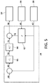
- Figure 5 details the control algorithm used for estimating the position of the fulcrum 48.
- the method proposed for obtaining the estimation of the fulcrum point 48 depends on the type of orientation mechanism of the laparoscopic tool installed in the end effector of the robotic unit.
- this orientation mechanism of the laparoscopic tool (or minimally invasive instrument) is performed by means of direct actuation and is discussed in further detail according to the illustration of Figure 4 . If the actual location of the fulcrum point ⁇ R ⁇ P I 57 (see Figures 3 and 4 ) is different from the estimated location, the error in the positioning ⁇ R ⁇ ⁇ I of the fulcrum generates an unwanted abdominal force ⁇ R ⁇ F I 63 on the abdominal wall 53. The abdominal force ⁇ R ⁇ F I 63 can be measured with the force sensor coupled in the end effector 55 of the robot.
- the gain K I is obtained in a general manner based on experimental testing in which the force of interaction with the fulcrum F I 63 for known movements ⁇ I is measured.
- a gain C I ⁇ 1, the value of which is chosen to meet the rapid response criteria for a feedback loop and to ensure stability of the control algorithm is applied to this result.
- Figure 5 shows the control algorithm used for estimating the position of the fulcrum 48 according to the method set forth above.
- the external distance p 67 is calculated based on the expression [5], i.e., the external distance p 67 is calculated based on the current Cartesian orientation ⁇ R ⁇ z 45 coming from the forward kinematics 26 and the contribution of the forces ⁇ R ⁇ F I and moments ⁇ R ⁇ M I of interaction with the abdominal wall 47 coming from the interaction model 28.
- This contribution of the forces ⁇ R ⁇ F I and moments ⁇ R ⁇ M I of interaction with the abdominal wall 47 is provided as feedback, being subtracted from a desired reference force ⁇ R ⁇ F 0 68 for the interaction with the abdominal wall.
- the result 69 of this subtraction is weighted with the control gain C I 65, and the result of this weighting 70 is converted from a magnitude in forces to a magnitude in distances with conversion factor K I 66.
- the result of that conversion 71 is added to the estimation vector of the external distance p ⁇ R ⁇ z 72 for finally obtaining the Cartesian position ⁇ R ⁇ P , of the fulcrum point 48 and sending it to the navigation model 19 for programming the spherical navigation.
- the stiffness estimator 30 represents an algorithm which is in charge of estimating in a dynamic manner the stiffness of the tissue in contact with the distal end of the tool by means of the offset force and moment measurement resulting from the interaction with the internal tissue of the patient 49 (obtained by the interaction model 28), such that the relationship between the force and the movement of interaction with the internal tissue of the patient can be modelled with a linear system.
- This estimation of the stiffness of the internal tissue of the patient is part of a least squares estimation algorithm, the purpose of which is to stabilise the value of the stiffness of the internal tissue with the smallest possible delay, whereby the perception of contact of the hands of the surgeon 14 through the haptic devices 15 can be distinguished between solid and soft objects.
- a simulated reaction force 50 proportional to the movement 51 of the haptic device 15 performed by the hand of the surgeon 14, is calculated taking as a reference the position of the haptic device 15 in which a force and moment measurement 49 resulting from the interaction with the internal tissue of the patient 49 was first detected. That simulated reaction force 50 is scaled so as to perceive the contact in the hands of the surgeon as a natural reaction, and is subsequently sent to the actuators of the haptic device 15.
- the control algorithm of the stiffness estimator 30 of Figure 2 is detailed in Figure 6 and is in charge of modelling the force perceived by the robotic unit as a simulated force ⁇ H ⁇ F H 50 acting in the direction opposite the movement of the haptic device 15.
- This force is simulated by means of an elastic-linear force reaction model 73 with dynamic stiffness K T , the point of equilibrium of which is based on the last haptic position ⁇ H ⁇ P H 0 and the current haptic position of which is ⁇ H ⁇ P H 32.
- a scaling factor K F ⁇ 1 74 is applied to improve system stability.
- the dynamic stiffness K T is a variable parameter which enables different resistances to be perceived in the haptic 15 depending on the material in contact with the laparoscopic tool. For this reason, it is necessary to determine this magnitude as a function of the measurements of forces ⁇ R ⁇ F T of interaction with the internal tissue 49 obtained from the actual surroundings of the robotic unit 23 through the interaction model 28.
- K T N + 1 K T N + F T ⁇ ⁇ P T N ⁇ K T N ⁇ P T N ⁇ C N 1 + ⁇ P T 2 N ⁇ C N
- the method of the invention overcomes the main limitations detected in the state of the art as has been explained: Relative to conventional control methods, which allow the surgeon to perceive the interaction of forces between the surgical tools and the patient, but such proposals do not take into account the overlapping of forces exerted by the laparoscopic tool on the point of insertion and manipulation forces relative to the internal tissue of the patient:
- the described method takes into account in that force and moment measurement between the surgical tools and the patient what percentage of the measurement results from the interaction with the fulcrum point and what percentage of the measurement results from the interaction with the internal tissue of the patient.
- Contact forces on the fulcrum occur when the pivoting movements of the laparoscopic tool are performed around a point which does not coincide with the fulcrum, i.e., when an erroneous estimation of the point of insertion takes place.
- Contact forces on the distal end occur when an interaction between the laparoscopic tool and the internal tissue of the patient takes place. Both components of the contact force can be produced simultaneously, but the force and moment measurement device compiles the measurement of the sum total of the contact forces.
- the method models the contact forces and is capable of separating the contributions of the reaction forces and the manipulation forces to the measurement.
- Each manipulator arm has a force control system which uses, on one hand, the manipulation force for obtaining an estimation of the stiffness of the internal tissue of the patient for modelling a contact force with a hard or soft tissue which is subsequently provided as feedback to the haptic interface, and on the other hand, the reaction force for obtaining a better estimation of the position of the point of insertion for minimising the magnitude of said force by means of programming paths of the laparoscopic tool around the actual point of insertion.
- the described method estimates the position of the fulcrum point with equation [7].
- a control algorithm ( Figure 5 ) which moves the laparoscopic tool of the robot in order for it to be aligned along the fulcrum is applied, such that it minimises the force exerted on the abdominal wall of the patient.
- this estimation of the position of the fulcrum is used for performing spherical navigation and in order for the new movements of the laparoscopic tool to be performed around this point.
- the described method allows selecting, through an interface of the control console (for example through a touch screen), a type of movement of the minimally invasive instrument: a first type in which the movement of the haptic device is related to the movement of the distal end of the minimally invasive instrument; or a second type in which the movement of the haptic device is related to the movement of the effector of the manipulator arm (i.e. with the proximal end of the minimally invasive instrument), such that the pivoting movements of a manual minimally invasive instrument are simulated through the haptic device.
Landscapes
- Engineering & Computer Science (AREA)
- Health & Medical Sciences (AREA)
- Life Sciences & Earth Sciences (AREA)
- Surgery (AREA)
- Robotics (AREA)
- Molecular Biology (AREA)
- Biomedical Technology (AREA)
- Veterinary Medicine (AREA)
- Public Health (AREA)
- Nuclear Medicine, Radiotherapy & Molecular Imaging (AREA)
- General Health & Medical Sciences (AREA)
- Animal Behavior & Ethology (AREA)
- Medical Informatics (AREA)
- Heart & Thoracic Surgery (AREA)
- General Engineering & Computer Science (AREA)
- Theoretical Computer Science (AREA)
- Human Computer Interaction (AREA)
- Physics & Mathematics (AREA)
- General Physics & Mathematics (AREA)
- Mechanical Engineering (AREA)
- Manipulator (AREA)
Applications Claiming Priority (2)
| Application Number | Priority Date | Filing Date | Title |
|---|---|---|---|
| ES201630855A ES2607227B2 (es) | 2016-06-23 | 2016-06-23 | Método de manejo de un sistema robótico para cirugía mínimamente invasiva |
| PCT/ES2017/070456 WO2017220844A1 (es) | 2016-06-23 | 2017-06-22 | Método de manejo de un sistema robótico para cirugía mínimamente invasiva |
Publications (3)
| Publication Number | Publication Date |
|---|---|
| EP3473202A1 EP3473202A1 (en) | 2019-04-24 |
| EP3473202A4 EP3473202A4 (en) | 2020-02-19 |
| EP3473202B1 true EP3473202B1 (en) | 2021-03-03 |
Family
ID=58418515
Family Applications (1)
| Application Number | Title | Priority Date | Filing Date |
|---|---|---|---|
| EP17814810.2A Active EP3473202B1 (en) | 2016-06-23 | 2017-06-22 | Robotic system for minimally invasive surgery |
Country Status (3)
| Country | Link |
|---|---|
| EP (1) | EP3473202B1 (es) |
| ES (2) | ES2607227B2 (es) |
| WO (1) | WO2017220844A1 (es) |
Families Citing this family (9)
| Publication number | Priority date | Publication date | Assignee | Title |
|---|---|---|---|---|
| JP7244985B2 (ja) * | 2017-05-19 | 2023-03-23 | 川崎重工業株式会社 | 操作装置及び操作システム |
| RU2736162C2 (ru) * | 2019-04-29 | 2020-11-12 | федеральное государственное бюджетное образовательное учреждение высшего образования "Московский государственный медико-стоматологический университет имени А.И. Евдокимова" Министерства здравоохранения Российской Федерации (ФГБОУ ВО МГМСУ им. А.И. Евдокимова Минздрава России) | Многофункциональное устройство со сменными хирургическими инструментами для измерения воздействующих на них сил и моментов при проведении нейрохирургических операций |
| WO2022074535A1 (en) * | 2020-10-07 | 2022-04-14 | Auris Health, Inc. | System and method of activating manual manipulation using linkage interaction sensing |
| EP3995099A1 (en) * | 2020-11-10 | 2022-05-11 | Rob Surgical Systems, SL | Adaptative robotic system and method for the evaluation of the position of a trocar in a robotic laparoscopic surgery intervention |
| US20220192767A1 (en) * | 2020-12-21 | 2022-06-23 | Ethicon Llc | Dynamic trocar positioning for robotic surgical system |
| CN113633387B (zh) * | 2021-06-21 | 2024-01-26 | 安徽理工大学 | 术野追踪的扶持腹腔镜微创机器人触力交互方法和系统 |
| CN114700932A (zh) * | 2022-04-29 | 2022-07-05 | 清华大学 | 面向机械臂仿真到实际运动的逆运动学建模方法及装置 |
| WO2023220291A1 (en) * | 2022-05-11 | 2023-11-16 | Intuitive Surgical Operations, Inc. | Techniques for controlling a computer-assisted system |
| WO2024081301A1 (en) * | 2022-10-12 | 2024-04-18 | Intuitive Surgical Operations, Inc. | Systems and methods for control of a surgical system |
Family Cites Families (5)
| Publication number | Priority date | Publication date | Assignee | Title |
|---|---|---|---|---|
| US20070018958A1 (en) * | 2003-10-24 | 2007-01-25 | Tavakoli Seyed M | Force reflective robotic control system and minimally invasive surgical device |
| WO2007136770A2 (en) * | 2006-05-19 | 2007-11-29 | Mako Surgical Corp. | System and method for verifying calibration of a surgical device |
| EP1915963A1 (en) * | 2006-10-25 | 2008-04-30 | The European Atomic Energy Community (EURATOM), represented by the European Commission | Force estimation for a minimally invasive robotic surgery system |
| GB201406821D0 (en) * | 2014-04-16 | 2014-05-28 | Univ Leuven Kath | Method and device for estimating an optimal pivot point |
| JP2018500058A (ja) * | 2014-10-24 | 2018-01-11 | コヴィディエン リミテッド パートナーシップ | ロボット外科手術用システムアクセスポートの感知 |
-
2016
- 2016-06-23 ES ES201630855A patent/ES2607227B2/es active Active
-
2017
- 2017-06-22 WO PCT/ES2017/070456 patent/WO2017220844A1/es unknown
- 2017-06-22 ES ES17814810T patent/ES2877800T3/es active Active
- 2017-06-22 EP EP17814810.2A patent/EP3473202B1/en active Active
Non-Patent Citations (1)
| Title |
|---|
| None * |
Also Published As
| Publication number | Publication date |
|---|---|
| ES2877800T3 (es) | 2021-11-17 |
| EP3473202A1 (en) | 2019-04-24 |
| ES2607227B2 (es) | 2017-11-23 |
| WO2017220844A1 (es) | 2017-12-28 |
| EP3473202A4 (en) | 2020-02-19 |
| ES2607227A1 (es) | 2017-03-29 |
Similar Documents
| Publication | Publication Date | Title |
|---|---|---|
| EP3473202B1 (en) | Robotic system for minimally invasive surgery | |
| US11950870B2 (en) | Computer-assisted tele-operated surgery systems and methods | |
| US11596483B2 (en) | Motion execution of a robotic system | |
| US11676511B2 (en) | System with emulator movement tracking for controlling medical devices | |
| JP6956081B2 (ja) | ロボットシステム及びロボットシステムをバックドライブする方法 | |
| KR102206198B1 (ko) | 수술 로봇 시스템 및 그 제어 방법 | |
| US9566124B2 (en) | Methods for handling an operator command exceeding a medical device state limitation in a medical robotic system | |
| KR102189666B1 (ko) | 기계 몸체의 운동을 조종하기 위한 가상 자유도 | |
| EP2942029A1 (en) | Surgical robots and control methods thereof | |
| US20080154246A1 (en) | Grip strength with tactile feedback for robotic surgery | |
| EP2047805A1 (en) | Robotic system for assisting in minimally-invasive surgery, which can position a surgical instrument in response to orders from a surgeon, is not attached to the operating table and does not require pre-calibration of the insertion point | |
| Vandini et al. | Vision-based motion control of a flexible robot for surgical applications | |
| WO2021188146A1 (en) | Trocar pose estimation using machine learning for docking surgical robotic arm to trocar | |
| Zemiti et al. | A force controlled laparoscopic surgical robot without distal force sensing | |
| Gibo et al. | Design considerations and human-machine performance of moving virtual fixtures | |
| Bihlmaier et al. | Endoscope robots and automated camera guidance | |
| Dong | Assistance to laparoscopic surgery through comanipulation | |
| JP2020532406A (ja) | ロボット手術システムのための衝突処理アルゴリズム | |
| Mago et al. | Fall detection for robotic endoscope holders in Minimally Invasive Surgery | |
| EP3829826B1 (en) | Systems and methods for controlling a robotic manipulator or associated tool | |
| US20230414307A1 (en) | Systems and methods for remote mentoring | |
| Bauzano et al. | Three-layer control for active wrists in robotized laparoscopic surgery | |
| Yılmaz | Development of a Sensorless Haptic Teleoperation System for Robotic Minimally Invasive Surgery | |
| WO2022221204A1 (en) | Controlled resistance in backdrivable joints | |
| Nia Kosari | Haptic Virtual Fixtures for Robotic Surgery |
Legal Events
| Date | Code | Title | Description |
|---|---|---|---|
| STAA | Information on the status of an ep patent application or granted ep patent |
Free format text: STATUS: THE INTERNATIONAL PUBLICATION HAS BEEN MADE |
|
| PUAI | Public reference made under article 153(3) epc to a published international application that has entered the european phase |
Free format text: ORIGINAL CODE: 0009012 |
|
| STAA | Information on the status of an ep patent application or granted ep patent |
Free format text: STATUS: REQUEST FOR EXAMINATION WAS MADE |
|
| 17P | Request for examination filed |
Effective date: 20181220 |
|
| AK | Designated contracting states |
Kind code of ref document: A1 Designated state(s): AL AT BE BG CH CY CZ DE DK EE ES FI FR GB GR HR HU IE IS IT LI LT LU LV MC MK MT NL NO PL PT RO RS SE SI SK SM TR |
|
| AX | Request for extension of the european patent |
Extension state: BA ME |
|
| DAV | Request for validation of the european patent (deleted) | ||
| DAX | Request for extension of the european patent (deleted) | ||
| A4 | Supplementary search report drawn up and despatched |
Effective date: 20200117 |
|
| RIC1 | Information provided on ipc code assigned before grant |
Ipc: A61B 34/35 20160101ALI20200113BHEP Ipc: B25J 13/02 20060101ALI20200113BHEP Ipc: A61B 34/30 20160101ALI20200113BHEP Ipc: A61B 34/00 20160101ALI20200113BHEP Ipc: B25J 9/16 20060101ALI20200113BHEP Ipc: A61B 34/37 20160101AFI20200113BHEP Ipc: B25J 18/00 20060101ALI20200113BHEP Ipc: G06F 3/01 20060101ALI20200113BHEP Ipc: B25J 13/08 20060101ALI20200113BHEP |
|
| REG | Reference to a national code |
Ref country code: DE Ref legal event code: R079 Ref document number: 602017033984 Country of ref document: DE Free format text: PREVIOUS MAIN CLASS: A61B0034370000 Ipc: B25J0013020000 |
|
| GRAP | Despatch of communication of intention to grant a patent |
Free format text: ORIGINAL CODE: EPIDOSNIGR1 |
|
| STAA | Information on the status of an ep patent application or granted ep patent |
Free format text: STATUS: GRANT OF PATENT IS INTENDED |
|
| RIC1 | Information provided on ipc code assigned before grant |
Ipc: A61B 34/30 20160101ALI20200819BHEP Ipc: B25J 13/02 20060101AFI20200819BHEP Ipc: A61B 90/00 20160101ALN20200819BHEP Ipc: A61B 34/00 20160101ALN20200819BHEP Ipc: A61B 34/10 20160101ALI20200819BHEP |
|
| RIC1 | Information provided on ipc code assigned before grant |
Ipc: A61B 34/10 20160101ALI20200827BHEP Ipc: A61B 34/30 20160101ALI20200827BHEP Ipc: B25J 13/02 20060101AFI20200827BHEP Ipc: A61B 90/00 20160101ALN20200827BHEP Ipc: A61B 34/00 20160101ALN20200827BHEP |
|
| INTG | Intention to grant announced |
Effective date: 20200922 |
|
| GRAS | Grant fee paid |
Free format text: ORIGINAL CODE: EPIDOSNIGR3 |
|
| STAA | Information on the status of an ep patent application or granted ep patent |
Free format text: STATUS: GRANT OF PATENT IS INTENDED |
|
| GRAA | (expected) grant |
Free format text: ORIGINAL CODE: 0009210 |
|
| STAA | Information on the status of an ep patent application or granted ep patent |
Free format text: STATUS: THE PATENT HAS BEEN GRANTED |
|
| AK | Designated contracting states |
Kind code of ref document: B1 Designated state(s): AL AT BE BG CH CY CZ DE DK EE ES FI FR GB GR HR HU IE IS IT LI LT LU LV MC MK MT NL NO PL PT RO RS SE SI SK SM TR |
|
| REG | Reference to a national code |
Ref country code: GB Ref legal event code: FG4D |
|
| REG | Reference to a national code |
Ref country code: AT Ref legal event code: REF Ref document number: 1366699 Country of ref document: AT Kind code of ref document: T Effective date: 20210315 Ref country code: CH Ref legal event code: EP |
|
| REG | Reference to a national code |
Ref country code: DE Ref legal event code: R096 Ref document number: 602017033984 Country of ref document: DE |
|
| REG | Reference to a national code |
Ref country code: IE Ref legal event code: FG4D |
|
| REG | Reference to a national code |
Ref country code: LT Ref legal event code: MG9D |
|
| PG25 | Lapsed in a contracting state [announced via postgrant information from national office to epo] |
Ref country code: NO Free format text: LAPSE BECAUSE OF FAILURE TO SUBMIT A TRANSLATION OF THE DESCRIPTION OR TO PAY THE FEE WITHIN THE PRESCRIBED TIME-LIMIT Effective date: 20210603 Ref country code: HR Free format text: LAPSE BECAUSE OF FAILURE TO SUBMIT A TRANSLATION OF THE DESCRIPTION OR TO PAY THE FEE WITHIN THE PRESCRIBED TIME-LIMIT Effective date: 20210303 Ref country code: FI Free format text: LAPSE BECAUSE OF FAILURE TO SUBMIT A TRANSLATION OF THE DESCRIPTION OR TO PAY THE FEE WITHIN THE PRESCRIBED TIME-LIMIT Effective date: 20210303 Ref country code: BG Free format text: LAPSE BECAUSE OF FAILURE TO SUBMIT A TRANSLATION OF THE DESCRIPTION OR TO PAY THE FEE WITHIN THE PRESCRIBED TIME-LIMIT Effective date: 20210603 Ref country code: LT Free format text: LAPSE BECAUSE OF FAILURE TO SUBMIT A TRANSLATION OF THE DESCRIPTION OR TO PAY THE FEE WITHIN THE PRESCRIBED TIME-LIMIT Effective date: 20210303 |
|
| REG | Reference to a national code |
Ref country code: NL Ref legal event code: MP Effective date: 20210303 |
|
| REG | Reference to a national code |
Ref country code: AT Ref legal event code: MK05 Ref document number: 1366699 Country of ref document: AT Kind code of ref document: T Effective date: 20210303 |
|
| PG25 | Lapsed in a contracting state [announced via postgrant information from national office to epo] |
Ref country code: SE Free format text: LAPSE BECAUSE OF FAILURE TO SUBMIT A TRANSLATION OF THE DESCRIPTION OR TO PAY THE FEE WITHIN THE PRESCRIBED TIME-LIMIT Effective date: 20210303 Ref country code: RS Free format text: LAPSE BECAUSE OF FAILURE TO SUBMIT A TRANSLATION OF THE DESCRIPTION OR TO PAY THE FEE WITHIN THE PRESCRIBED TIME-LIMIT Effective date: 20210303 Ref country code: LV Free format text: LAPSE BECAUSE OF FAILURE TO SUBMIT A TRANSLATION OF THE DESCRIPTION OR TO PAY THE FEE WITHIN THE PRESCRIBED TIME-LIMIT Effective date: 20210303 Ref country code: PL Free format text: LAPSE BECAUSE OF FAILURE TO SUBMIT A TRANSLATION OF THE DESCRIPTION OR TO PAY THE FEE WITHIN THE PRESCRIBED TIME-LIMIT Effective date: 20210303 |
|
| PG25 | Lapsed in a contracting state [announced via postgrant information from national office to epo] |
Ref country code: NL Free format text: LAPSE BECAUSE OF FAILURE TO SUBMIT A TRANSLATION OF THE DESCRIPTION OR TO PAY THE FEE WITHIN THE PRESCRIBED TIME-LIMIT Effective date: 20210303 |
|
| PG25 | Lapsed in a contracting state [announced via postgrant information from national office to epo] |
Ref country code: SM Free format text: LAPSE BECAUSE OF FAILURE TO SUBMIT A TRANSLATION OF THE DESCRIPTION OR TO PAY THE FEE WITHIN THE PRESCRIBED TIME-LIMIT Effective date: 20210303 Ref country code: AT Free format text: LAPSE BECAUSE OF FAILURE TO SUBMIT A TRANSLATION OF THE DESCRIPTION OR TO PAY THE FEE WITHIN THE PRESCRIBED TIME-LIMIT Effective date: 20210303 Ref country code: EE Free format text: LAPSE BECAUSE OF FAILURE TO SUBMIT A TRANSLATION OF THE DESCRIPTION OR TO PAY THE FEE WITHIN THE PRESCRIBED TIME-LIMIT Effective date: 20210303 Ref country code: CZ Free format text: LAPSE BECAUSE OF FAILURE TO SUBMIT A TRANSLATION OF THE DESCRIPTION OR TO PAY THE FEE WITHIN THE PRESCRIBED TIME-LIMIT Effective date: 20210303 |
|
| REG | Reference to a national code |
Ref country code: ES Ref legal event code: FG2A Ref document number: 2877800 Country of ref document: ES Kind code of ref document: T3 Effective date: 20211117 |
|
| PG25 | Lapsed in a contracting state [announced via postgrant information from national office to epo] |
Ref country code: PT Free format text: LAPSE BECAUSE OF FAILURE TO SUBMIT A TRANSLATION OF THE DESCRIPTION OR TO PAY THE FEE WITHIN THE PRESCRIBED TIME-LIMIT Effective date: 20210705 Ref country code: SK Free format text: LAPSE BECAUSE OF FAILURE TO SUBMIT A TRANSLATION OF THE DESCRIPTION OR TO PAY THE FEE WITHIN THE PRESCRIBED TIME-LIMIT Effective date: 20210303 Ref country code: RO Free format text: LAPSE BECAUSE OF FAILURE TO SUBMIT A TRANSLATION OF THE DESCRIPTION OR TO PAY THE FEE WITHIN THE PRESCRIBED TIME-LIMIT Effective date: 20210303 Ref country code: IS Free format text: LAPSE BECAUSE OF FAILURE TO SUBMIT A TRANSLATION OF THE DESCRIPTION OR TO PAY THE FEE WITHIN THE PRESCRIBED TIME-LIMIT Effective date: 20210703 |
|
| REG | Reference to a national code |
Ref country code: DE Ref legal event code: R097 Ref document number: 602017033984 Country of ref document: DE |
|
| PLBE | No opposition filed within time limit |
Free format text: ORIGINAL CODE: 0009261 |
|
| STAA | Information on the status of an ep patent application or granted ep patent |
Free format text: STATUS: NO OPPOSITION FILED WITHIN TIME LIMIT |
|
| PG25 | Lapsed in a contracting state [announced via postgrant information from national office to epo] |
Ref country code: DK Free format text: LAPSE BECAUSE OF FAILURE TO SUBMIT A TRANSLATION OF THE DESCRIPTION OR TO PAY THE FEE WITHIN THE PRESCRIBED TIME-LIMIT Effective date: 20210303 Ref country code: AL Free format text: LAPSE BECAUSE OF FAILURE TO SUBMIT A TRANSLATION OF THE DESCRIPTION OR TO PAY THE FEE WITHIN THE PRESCRIBED TIME-LIMIT Effective date: 20210303 Ref country code: MC Free format text: LAPSE BECAUSE OF FAILURE TO SUBMIT A TRANSLATION OF THE DESCRIPTION OR TO PAY THE FEE WITHIN THE PRESCRIBED TIME-LIMIT Effective date: 20210303 |
|
| REG | Reference to a national code |
Ref country code: CH Ref legal event code: PL |
|
| 26N | No opposition filed |
Effective date: 20211206 |
|
| PG25 | Lapsed in a contracting state [announced via postgrant information from national office to epo] |
Ref country code: SI Free format text: LAPSE BECAUSE OF FAILURE TO SUBMIT A TRANSLATION OF THE DESCRIPTION OR TO PAY THE FEE WITHIN THE PRESCRIBED TIME-LIMIT Effective date: 20210303 |
|
| REG | Reference to a national code |
Ref country code: BE Ref legal event code: MM Effective date: 20210630 |
|
| PG25 | Lapsed in a contracting state [announced via postgrant information from national office to epo] |
Ref country code: LU Free format text: LAPSE BECAUSE OF NON-PAYMENT OF DUE FEES Effective date: 20210622 |
|
| PG25 | Lapsed in a contracting state [announced via postgrant information from national office to epo] |
Ref country code: LI Free format text: LAPSE BECAUSE OF NON-PAYMENT OF DUE FEES Effective date: 20210630 Ref country code: IT Free format text: LAPSE BECAUSE OF FAILURE TO SUBMIT A TRANSLATION OF THE DESCRIPTION OR TO PAY THE FEE WITHIN THE PRESCRIBED TIME-LIMIT Effective date: 20210303 Ref country code: IE Free format text: LAPSE BECAUSE OF NON-PAYMENT OF DUE FEES Effective date: 20210622 Ref country code: CH Free format text: LAPSE BECAUSE OF NON-PAYMENT OF DUE FEES Effective date: 20210630 |
|
| PG25 | Lapsed in a contracting state [announced via postgrant information from national office to epo] |
Ref country code: IS Free format text: LAPSE BECAUSE OF FAILURE TO SUBMIT A TRANSLATION OF THE DESCRIPTION OR TO PAY THE FEE WITHIN THE PRESCRIBED TIME-LIMIT Effective date: 20210703 |
|
| PG25 | Lapsed in a contracting state [announced via postgrant information from national office to epo] |
Ref country code: BE Free format text: LAPSE BECAUSE OF NON-PAYMENT OF DUE FEES Effective date: 20210630 |
|
| PGFP | Annual fee paid to national office [announced via postgrant information from national office to epo] |
Ref country code: GB Payment date: 20220503 Year of fee payment: 6 Ref country code: FR Payment date: 20220503 Year of fee payment: 6 |
|
| PGFP | Annual fee paid to national office [announced via postgrant information from national office to epo] |
Ref country code: ES Payment date: 20220701 Year of fee payment: 6 Ref country code: DE Payment date: 20220629 Year of fee payment: 6 |
|
| PG25 | Lapsed in a contracting state [announced via postgrant information from national office to epo] |
Ref country code: CY Free format text: LAPSE BECAUSE OF FAILURE TO SUBMIT A TRANSLATION OF THE DESCRIPTION OR TO PAY THE FEE WITHIN THE PRESCRIBED TIME-LIMIT Effective date: 20210303 |
|
| PG25 | Lapsed in a contracting state [announced via postgrant information from national office to epo] |
Ref country code: HU Free format text: LAPSE BECAUSE OF FAILURE TO SUBMIT A TRANSLATION OF THE DESCRIPTION OR TO PAY THE FEE WITHIN THE PRESCRIBED TIME-LIMIT; INVALID AB INITIO Effective date: 20170622 Ref country code: GR Free format text: LAPSE BECAUSE OF FAILURE TO SUBMIT A TRANSLATION OF THE DESCRIPTION OR TO PAY THE FEE WITHIN THE PRESCRIBED TIME-LIMIT Effective date: 20210303 |
|
| REG | Reference to a national code |
Ref country code: DE Ref legal event code: R082 Ref document number: 602017033984 Country of ref document: DE Representative=s name: GLEIM PETRI PATENT- UND RECHTSANWALTSPARTNERSC, DE |
|
| REG | Reference to a national code |
Ref country code: DE Ref legal event code: R119 Ref document number: 602017033984 Country of ref document: DE |
|
| GBPC | Gb: european patent ceased through non-payment of renewal fee |
Effective date: 20230622 |
|
| PG25 | Lapsed in a contracting state [announced via postgrant information from national office to epo] |
Ref country code: MK Free format text: LAPSE BECAUSE OF FAILURE TO SUBMIT A TRANSLATION OF THE DESCRIPTION OR TO PAY THE FEE WITHIN THE PRESCRIBED TIME-LIMIT Effective date: 20210303 Ref country code: DE Free format text: LAPSE BECAUSE OF NON-PAYMENT OF DUE FEES Effective date: 20240103 Ref country code: GB Free format text: LAPSE BECAUSE OF NON-PAYMENT OF DUE FEES Effective date: 20230622 |