EP3472094B1 - Technische barriere und verfahren zur gewährleistung der sicherheit von entladungsoperationen - Google Patents
Technische barriere und verfahren zur gewährleistung der sicherheit von entladungsoperationen Download PDFInfo
- Publication number
- EP3472094B1 EP3472094B1 EP17742804.2A EP17742804A EP3472094B1 EP 3472094 B1 EP3472094 B1 EP 3472094B1 EP 17742804 A EP17742804 A EP 17742804A EP 3472094 B1 EP3472094 B1 EP 3472094B1
- Authority
- EP
- European Patent Office
- Prior art keywords
- unloaded
- unloading
- barrier
- technical barrier
- parameter
- Prior art date
- Legal status (The legal status is an assumption and is not a legal conclusion. Google has not performed a legal analysis and makes no representation as to the accuracy of the status listed.)
- Active
Links
Images


Classifications
-
- B—PERFORMING OPERATIONS; TRANSPORTING
- B67—OPENING, CLOSING OR CLEANING BOTTLES, JARS OR SIMILAR CONTAINERS; LIQUID HANDLING
- B67D—DISPENSING, DELIVERING OR TRANSFERRING LIQUIDS, NOT OTHERWISE PROVIDED FOR
- B67D7/00—Apparatus or devices for transferring liquids from bulk storage containers or reservoirs into vehicles or into portable containers, e.g. for retail sale purposes
- B67D7/06—Details or accessories
- B67D7/32—Arrangements of safety or warning devices; Means for preventing unauthorised delivery of liquid
- B67D7/34—Means for preventing unauthorised delivery of liquid
- B67D7/342—Means for preventing unauthorised delivery of liquid by discriminating the kind of liquid by analysis or by physical properties, e.g. vapour-pressure
-
- G—PHYSICS
- G01—MEASURING; TESTING
- G01N—INVESTIGATING OR ANALYSING MATERIALS BY DETERMINING THEIR CHEMICAL OR PHYSICAL PROPERTIES
- G01N33/00—Investigating or analysing materials by specific methods not covered by groups G01N1/00 - G01N31/00
- G01N33/26—Oils; Viscous liquids; Paints; Inks
- G01N33/28—Oils, i.e. hydrocarbon liquids
- G01N33/2829—Mixtures of fuels
Definitions
- This presentation concerns a technical barrier for securing unloading as well as a process for securing unloading making it possible to verify the nature of the material to be unloaded in order to prevent a possible unloading accident.
- Such a barrier or process can be used in particular on industrial sites to reduce the risk of unloading error and therefore the risk of formation of an incompatible mixture of two chemical materials which can lead to an explosion or the release of toxic gases.
- the present presentation relates to a technical barrier for securing unloading, comprising a barrier element configured to block or let through a material to be unloaded according to a command addressed to it, a measuring element configured to measure at least one parameter of the material to be unloaded, a validation module configured to compare at least one parameter measured by said measuring element with a pre-recorded theoretical parameter for the material expected for unloading, and to determine, on the basis of this comparison, whether the material to be unloading corresponds to the material expected for unloading, and a control module configured to control the dam element according to the results of this determination.
- the measuring element is an online analyzer configured to measure at least one parameter of the material to be decanted without sampling material. Thanks to such an on-line analyzer, it is possible to carry out the measurement in situ and in real time without having to take material, which may be dangerous, and analyze it in a separate laboratory, delaying the unloading operations. In addition, such an on-line analyzer makes it possible to repeat the measurement, if necessary, during unloading.
- the online analyzer is configured to measure at least one parameter of the material to be decanted without contact with said material to be decanted. Since the material to be removed can be dangerous, corrosive for example, this prevents the material to be removed from damaging the analyzer, which prolongs its life. The drift of the analyzer is also avoided, thus allowing a reduction in the cost of maintenance of the analyzer.
- the measuring element is a spectrometer, preferably of the Raman type.
- the measurement of a spectrum whether Raman, infrared, NMR or of another nature, makes it possible to obtain a precise characterization of the material analyzed, each chemical substance having its own spectrum. This reinforces the reliability of the technical barrier.
- Raman spectroscopy is preferred, in particular compared to infrared spectroscopy, because it makes it possible to easily identify a chemical substance even when the latter is diluted, in particular in water.
- the measuring element can of course be of another type and measure one or more other parameters of the material to be discharged, in particular its pH or its density.
- the technical barrier comprises a pouring hole configured to receive the material to be deposited upstream of the dam element, the pouring hole having at least one transparent window at the level of which, preferably against which, the measuring element is provided.
- a pouring hole thus makes it possible to observe the material to be unloaded just upstream of the dam element: it is thus possible to set up the measuring element at the level of the pouring hole to have easy access to the material. to analyze.
- Such a sight glass is thus particularly useful when the measuring element is a spectrometer.
- the sight glass comprises a pipe made of transparent material, preferably glass.
- the technical barrier comprises a drain valve provided downstream of the manhole and upstream of the barrier element. This makes it possible to reduce the risk that a material resulting from a previous unloading does not remain in the casting hole and does not disturb the measurement of the measuring element.
- the technical barrier comprises an isolation valve provided between the manhole and the dam element.
- the technical barrier comprises an emptying verification module configured to verify that the emptying of the pouring hole is effective and to prohibit a subsequent unloading operation if this verification fails. This makes it possible to ensure that the manhole is indeed empty before starting a new unloading operation and therefore to ensure that the measurement carried out by the measuring element indeed relates to the material to be unloaded from the loading operation. unloading in progress.
- the technical barrier comprises a thermal insulation enclosure encompassing at least said measuring element in order to isolate it from the surrounding environment.
- a thermal insulation enclosure makes it possible to protect the measuring element from the cold in order to ensure proper operation and therefore good reliability of the latter.
- the thermal insulation enclosure also includes the casting hole.
- the isolation enclosure is an insulating envelope.
- the isolation enclosure is provided with a heating device, for example a heating cord. This makes it possible to regulate the temperature within the insulation enclosure and therefore to place the measuring element under favorable temperature conditions.
- the isolation enclosure is provided with a temperature sensor. This makes active thermal regulation possible within the insulation enclosure, the heating device being able in particular to be controlled as a function of the temperature measured by the temperature sensor.
- the technical barrier comprises a degassing device provided upstream of the measuring element. It may in particular be a purge valve positioned at the high point of the circulation. Such a degassing device makes it possible to evacuate any bubbles or pockets of gas present in the material to be decanted which could alter the operation of the measuring element.
- the validation module comprises an identification module having a database of theoretical parameters for a set of different materials and the identification module is configured to identify the material to be unloaded by comparing at least one parameter measured by the measuring element with the theoretical parameters from the database.
- the validation module makes it possible, thanks to this identification module, to identify the material to be unloaded if the latter is included in the database.
- the validation module includes a comparison module configured to compare a identification signature of the material to be unloaded provided by the identification module with a pre-recorded signature of the material expected for unloading.
- a comparison module configured to compare a identification signature of the material to be unloaded provided by the identification module with a pre-recorded signature of the material expected for unloading.
- the validation module is configured to determine whether the material to be unloaded corresponds to the material expected for unloading at least before the start of unloading. Any start of unloading and therefore any start of mixing is thus prohibited if the material to be unloaded is not that expected.
- the validation module is configured to determine whether the material to be unloaded corresponds to the material expected for the unloading during unloading. It is thus verified that the composition of the material to be unloaded does not change during unloading, for example in the event of the presence of several phases in the delivery truck. This verification preferably takes place at regular intervals,
- the validation module is further configured to check whether the communication between the measuring element, the validation module, the control module and/or the barrier element is well established. In this way, in the event of a communication fault, unloading is prohibited in any case: a situation is thus avoided in which an incompatible material would be unloaded by mistake due to an identification signal corrupted by a bad transmission or a persistence of an obsolete identification signal.
- the dam element is a pump.
- the pump when stopped, it prevents the flow of the material to be unloaded; conversely, when it is in operation, it causes the material to be unloaded and thus carries out the unloading.
- the barrier element is a valve, for example of the electromechanical type. So when she is closed, it prevents the flow of the material to be unloaded; conversely, when it is open, it allows the material to be unloaded to flow through the unloading pump.
- the technical barrier comprises a communication module configured to transmit to a supervision station data relating to the operation of the technical barrier and/or to the progress of the unloading.
- the technical barrier comprises a second measuring element configured to measure at least one parameter of the material to be unloaded, a second validation module configured to compare at least one parameter measured by said second measuring element with a parameter pre-recorded theoretical for the material expected for stripping, and determining, on the basis of this comparison, whether the material to be stripped corresponds to the material expected for stripping, and the control module is configured to control the dam element as a function the results of the determinations carried out by each of the validation modules.
- the second measuring element can be identical to the first measuring element; conversely, it can also measure a parameter different from that measured by the first measuring element.
- This presentation also relates to a method for securing unloading, comprising the following steps: setting up a barrier element between an upstream tank containing the material to be unloaded and a downstream tank intended to receive the material to be unloaded, the barrier element being configured to block or allow the material to be unloaded to pass depending on the command sent to it; measuring a parameter of the material to be discharged upstream of the barrier element; comparing this measured parameter with a theoretical parameter of the material expected for stripping and deducing therefrom whether the material to be stripped corresponds to the material expected for stripping; in the event that it is determined that the material to be unloaded corresponds to the material expected for the unloading, controlling the barrier element to allow the material to be unloaded to pass; in the event that it is determined that the material to be unloading does not correspond to the material expected for unloading, order the barrier element to block the material to be unloaded.
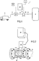
- FIG 1 shows a block diagram of a first embodiment of a technical barrier 1 provided to secure the unloading of a material to be unloaded from an upstream tank, here a truck 2, to a downstream tank 3.
- the technical barrier 1 comprises a conduit 10, provided with an upstream connection 11 and a downstream connection 12, on which are mounted a pump 20 and an online analyzer 30 provided upstream of the pump 20.
- This pump 20 has a control input 21 and is configured to operate, and therefore to drive the material to be unloaded from upstream to downstream in the technical barrier 1, when a control signal is sent to its control input 21 and to stop and remain stationary, and therefore to block the flow of the material to be unloaded in the technical barrier 1, when no control signal reaches its control input 21.
- the on-line analyzer 30 is mounted for its part on a seep 13 of the pipe 10.
- This seep 13 visible on the FIG 2 , comprises a totally transparent duct section 13a, here made of glass. It also comprises a plurality of bars 13b extending between the upstream 13c and downstream 13d flanges of the transparent conduit section 13a, coaxially and around the latter, with the aim of ensuring the mechanical strength of the sight glass 13.
- the online analyzer 30 is a Raman spectrometer whose lens is pressed against the transparent wall 13a of the casting hole 13. This Raman spectrometer 30 is thus capable of measuring the Raman spectrum of the material flowing in the casting hole 13 .
- Raman spectroscopy consists of sending monochromatic light onto the sample and analyzing the scattered light by measuring the frequency shift caused by the exchange of energy between the light ray and the material analyzed (Raman effect).
- the Raman 30 spectrometer thus makes it possible to obtain spectra such as that of FIG 3 , corresponding to the spectrum of sodium bisulphite, in which the luminous intensity I of the scattered light, expressed in units arbitrary frequencies (au), is given for each wave number N, expressed in cm -1 , that is to say for each Raman shift.
- each chemical substance active in Raman has its own Raman spectrum which allows it to be identified.
- the Raman spectrometer 30 is further provided with a database listing the Raman spectra of numerous chemical substances and including at least the spectrum of the material expected for the stripping, that is to say generally the material of the downstream tank 3.
- the Raman spectrometer 30 further comprises an identification module capable of comparing the measured spectrum with the spectra of its database in order to identify the material present in the pouring hole 13.
- the manhole 13 and the online analyzer 30 are enveloped in an insulating casing 70, thermally insulating the manhole 13 and the online analyzer 30 with respect to the external environment.
- This insulating envelope 70 is provided with a heating cord 71 and a temperature probe 72 for measuring the temperature within the insulating envelope 70.
- a second temperature probe can also be provided near the pipe 10, outside the insulating envelope 70, in order to measure the temperature of the external environment.
- the automaton 40 is configured to control the heating cord 71 according to the temperature measurements taken by the temperature probes 72 so as to regulate the temperature within the insulating envelope 70.
- the automaton controls the start of the heating when the interior temperature drops below a threshold temperature, for example 10° C., and controls the stopping of the heating when the interior temperature exceeds a ceiling temperature, for example 14° C.
- a timed shutdown condition can also be provided in any case, for example an automatic shutdown of the heating after 30 minutes of uninterrupted heating.
- the technical barrier 1 also comprises an industrial automaton 40 connected on the one hand to the online analyzer 30 (possibly through an electronic interface), on the other hand to the control input 21 of the pump 20 and comprising means of logical calculation. he is also connected to a control desk 50 equipped with buttons and control lights as well as to a remote supervision station 4.
- the technical barrier 1 is connected on the one hand to the downstream tank 3 thanks to its downstream connection 12 and on the other hand to the upstream tank 2 thanks to its upstream connection 11.
- the technical barrier 1 could be provided permanently on a given tank 3, in particular when the latter is intended to always contain the same material: in such a case, each tank 3 of the site could be equipped with a dedicated technical barrier 1.
- the material to be unloaded provided in the upstream tank 2 begins to flow by gravity into the barrier 1, filling in particular the manhole 13, until it is stopped by the pump 20 initially. off.
- An intermediate manual valve can also be provided between the manhole 13 and the pump 20.
- the automaton 40 An operator can then launch the unloading operation by pressing a launch button on the control panel 50. Based on this signal, the automaton 40 first launches a communication self-test with the analyzer 30 (or its interface when such an interface exists). If this communication test is positive, the automaton 40 then sends a control signal to the analyzer 30 asking it to start the analysis of the material to be unloaded; otherwise, the automaton 40 sends a signal to the control desk 50 to light a fault indicator. In the event of a fault, the operator must check the connection and the proper functioning of the analyzer 30 then press a fault clearing button on the control console 50 before restarting the unloading operation. In another example, provision could be made for the operator to be unable to acknowledge the fault, only an intervention in the PLC by an automation engineer can then acknowledge it after checking in particular the wiring and the inputs-outputs of the analyzer and the automaton.
- the analyzer 30 When the analyzer 30 receives the analysis launch signal from the automaton 40, it measures the Raman spectrum of the material to be unloaded present in the casting hole 13 then tries to identify it by comparing it with the spectra in its database. In the event of identification, the analyzer 30, possibly via its interface, sends a signal to the automaton forming the signature of the identified material. In the present example, this signature is coded in binary on four bits using four wires connected to all-or-nothing inputs of the automaton 40. In addition, a specific signature can be provided when the analyzer 30 failed to identify the material or when it encountered a defect.
- the automaton 40 compares the signature thus transmitted by the analyzer 30 with the signature of the material expected for unloading prerecorded in the automaton 40.
- the automaton 40 determines that there is a match, it sends a command to the control input 21 of the pump 20. Otherwise, it sends a signal to the control console 50 to light a fault indicator.
- the operator In the event of a fault, the operator must check that the correct upstream tank 2 has indeed been connected to barrier 1 or that the material contained in the upstream tank 2 is indeed that expected, then press a fault clear button on the console control 50 before restarting the unloading operation.
- the truck is returned.
- a diagnosis is established and each constituent element is checked and spare parts (cable, analyzer, interface, etc.) are implemented according to the diagnosis.
- the pump 20 When the pump 20 receives the control signal from the automaton 40, it starts and thus causes the transfer of the material to be unloaded from the upstream tank 2 to the downstream tank 3.
- the automaton regularly restarts the self-test of communication and the analysis of the matter to be unloaded.
- the automaton immediately ceases to send a control signal to the control input 21 of the pump 20 and triggers the lighting of a warning light.
- pump 20 stops as soon as during operation and again block the flow of the material to be discharged.
- the automaton transmits to the supervision station 4 information on the unloading process, in particular the status of the various control and fault signals and the identification signature of the material circulating in the technical barrier 1.
- FIG 4 shows a block diagram of a second embodiment of a technical barrier 101 provided for securing the unloading of a material to be unloaded from an upstream tank, here a truck 102, to a downstream tank 103.
- the structure and operation of this technical barrier 101 are quite similar to those of the technical barrier 1 of the first example so that only the differences with this first example will be described.
- the pump 120 comprises a first control input 121 and a second control input 122. It is thus configured to operate only when control signals reach both the first control input 121 and the second control input 122.
- the technical barrier 101 now comprises a first online analyzer 130 and a second online analyzer 131, both analogous to the online analyzer 30 of the first example, mounted one after the other on manholes , or a single manhole, of the conduit 110 of the technical barrier 101.
- the automaton 140 will check the communication with each of the analyzers 130, 131 then ask each of them to launch an analysis of the material to be unloaded: the result from the first analyzer 130 determines whether the automaton 140 sends a first control signal to the first input 121 of the pump 120 while the result of the second analyzer determines, completely independently, whether the automaton 140 sends a second control signal to the second control input 122 of the pump 120. Consequently, the pump 120 only starts, and therefore the unloading takes place, if the two analyzers 130 and 131 independently determine that the material to be unloaded is indeed the expected material for stripping.
- the technical barrier could comprise two independent automatons, the first connected to the first analyzer and to the first control input of the pump, and the second connected to the second analyzer and to the second control input. of the pump.
- FIG 5 shows a block diagram of a third embodiment of a technical barrier 201 provided for securing the unloading of a material to be unloaded from an upstream tank, here a truck 202, to a downstream tank 203.
- the structure and operation of this technical barrier 201 are quite similar to those of the technical barrier 1 of the first example so that only the differences with this first example will be described. It goes without saying, however, that the teachings of this third example embodiment are compatible with the second example embodiment.
- a degassing valve 261 is provided between the upstream connection 211 and the sight glass carrying the online analyzer 230. This degassing valve is provided more precisely at the high point of the pipe 210 so as to evacuate the gas possibly present in the material to be decanted before it enters the manhole.
- an isolation valve 262 is provided between the sight glass carrying the online analyzer 230 and the pump 220.
- a drain valve 263 is also provided downstream of the sight glass carrying the online analyzer 230 and upstream of the isolation valve 262. In this way, it is possible to empty the manhole by closing the isolation valve 262 and opening the drain valve 263, the emptying then taking place by gravity .
- the isolation valve 262 is equipped with a limit switch allowing information to be sent back to the controller 240 on the open or closed position of the isolation valve 262.
- a systematic emptying of the pouring hole and a vacuum test are carried out after each unloading operation.
- the automaton controls the stopping of the pump 220 and the closing of the isolation valve 262 then controls the opening of the drain valve. 263 so as to cause the gravity drain of the casting hole.
- isolation 262 and drain 263 valves are controlled by the automaton 240; however, in other instances, they could be manual.
- the on-line analyzer 230 performs a vacuum test in the lookhole thus drained.
- the analyzer 230 will detect an absence of material in the manhole and will transmit to the automaton 240 a signature corresponding to this scenario.
- the automaton 240 will thus confirm the success of the emptying, which is a prerequisite for the next unloading.
- the analyzer 230 will transmit to the automaton 240 the signature of the identified material.
- the automaton 240 will then light a fault indicator and will prohibit any new unloading unless a new emptying operation is carried out successfully.
Landscapes
- Chemical & Material Sciences (AREA)
- Engineering & Computer Science (AREA)
- Analytical Chemistry (AREA)
- Health & Medical Sciences (AREA)
- Life Sciences & Earth Sciences (AREA)
- General Physics & Mathematics (AREA)
- Immunology (AREA)
- Food Science & Technology (AREA)
- Medicinal Chemistry (AREA)
- Physics & Mathematics (AREA)
- Chemical Kinetics & Catalysis (AREA)
- Biochemistry (AREA)
- General Health & Medical Sciences (AREA)
- General Chemical & Material Sciences (AREA)
- Oil, Petroleum & Natural Gas (AREA)
- Pathology (AREA)
- Mechanical Engineering (AREA)
- Investigating, Analyzing Materials By Fluorescence Or Luminescence (AREA)
- Pit Excavations, Shoring, Fill Or Stabilisation Of Slopes (AREA)
- Sampling And Sample Adjustment (AREA)
- Sorting Of Articles (AREA)
- Barrages (AREA)
- Chutes (AREA)
Claims (15)
- Technische Barriere (1) zum Sichern von Entladungen, die umfasstein Sperrelement (20), das ausgelegt ist, um ein zu entladendes Material in Abhängigkeit von einem Befehl, der ihm geschickt wurde, zu blockieren oder passieren zu lassen,ein Messelement (30), das dem Sperrelement (20) vorgelagert vorgesehen und ausgelegt ist, um mindestens einen Parameter des zu entladenden Materials zu messen,ein Validierungsmodul (30-40), das ausgelegt ist, um mindestens einen von dem Messelement (30) gemessenen Parameter mit einem für das für das Entladen erwartete Material vorgespeicherten theoretischen Parameter zu vergleichen und auf der Basis dieses Vergleichs zu bestimmen, ob das zu entladende Material dem für das Entladen erwarteten Material entspricht, undein Steuermodul (40), das ausgelegt ist, um das Sperrelement (20) in Abhängigkeit von den Ergebnissen dieser Bestimmung zu steuern,dadurch gekennzeichnet, dass das Messelement ein Inline-Analysator (30) ist, der ausgelegt ist, um mindestens einen Parameter des zu entladenden Materials ohne Materialentnahme zu messen.
- Technische Barriere (1) nach Anspruch 1, wobei der Inline-Analysator (30) ausgelegt ist, um mindestens einen Parameter des zu entladenden Materials ohne Kontakt mit dem zu entladenden Material zu messen.
- Technische Barriere (1) nach Anspruch 2, wobei das Messelement ein Spektrometer (30), vorzugsweise vom Typ Raman, ist.
- Technische Barriere (1) nach einem der Ansprüche 1 bis 3, die ein Durchfluss-Schauglas (13) umfasst, das ausgelegt ist, um das zu entladende Material dem Sperrelement (20) vorgelagert aufzunehmen, wobei das Durchfluss-Schauglas (13) mindestens ein transparentes Fenster (13a) besitzt, in dessen Bereich das Messelement (30) vorgesehen ist.
- Technische Barriere (1) nach Anspruch 4, die ein Ablassventil (263) umfasst, das dem Durchfluss-Schauglas nachgelagert und dem Sperrelement (220) vorgelagert vorgesehen ist.
- Technische Barriere (1) nach einem der Ansprüche 1 bis 5, die einen thermisch isolierenden Behälter (70) umfasst, der mindestens das Messelement (30) umschließt, um es von der Umgebung zu isolieren.
- Technische Barriere (1) nach Anspruch 6, wobei der thermische isolierende Behälter (70) mit einer Heizvorrichtung (71), beispielsweise einem Heizkabel, versehen ist.
- Technische Barriere (1) nach einem der Ansprüche 1 bis 7, die eine Entgasungsvorrichtung (261) umfasst, die dem Messelement (230) vorgelagert vorgesehen ist.
- Technische Barriere (1) nach einem der Ansprüche 1 bis 8, wobei das Validierungsmodul ein Identifikationsmodul umfasst, das eine Datenbank mit theoretischen Parametern für eine Gesamtheit unterschiedlicher Materialien besitzt, und
wobei das Identifikationsmodul ausgelegt ist, um das zu entladende Material durch Vergleichen mindestens eines vom Messelement (30) gemessenen Parameters mit den theoretischen Parametern der Datenbank zu identifizieren. - Technische Barriere (1) nach Anspruch 9, wobei das Validierungsmodul ein Vergleichsmodul (40) umfasst, das ausgelegt ist, um eine Identifikationssignatur des zu entladenden Materials, die von dem Identifikationsmodul bereitgestellt wird, mit einer vorgespeicherten Signatur des für das Entladen erwarteten Materials zu vergleichen.
- Technische Barriere (1) nach einem der Ansprüche 1 bis 10, wobei das Validierungsmodul (30-40) ausgelegt ist, um zu bestimmen, ob das zu entladende Material dem für das Entladen erwarteten Material mindestens vor dem Beginn des Entladens und gegebenenfalls während des Entladens entspricht.
- Technische Barriere (1) nach einem der Ansprüche 1 bis 11, wobei das Sperrelement eine Pumpe (20) ist.
- Technische Barriere (1) nach einem der Ansprüche 1 bis 12, wobei das Sperrelement eine Pumpe (20) ist.
- Technische Barriere nach einem der Ansprüche 1 bis 13, die ein Kommunikationsmodul (40) umfasst, das ausgelegt ist, um an einen Kontrollposten (4) Daten zu übertragen, die sich auf den Betrieb der technischen Barriere (1) und/oder den Ablauf des Entladens beziehen.
- Verfahren zur Sicherung des Entladens, das die folgenden Schritte umfasst:Platzieren eines Sperrelements (20) zwischen einem vorgelagerten Tank (2), der das zu entladende Material enthält, und einem nachgelagerten Tank (3) zur Aufnahme des zu entladenden Materials, wobei das Sperrelement (20) ausgelegt ist, um das zu entladende Material in Abhängigkeit von einem ihm übermittelten Befehl zu blockieren oder passieren zu lassen,Messen eines Parameters des dem Sperrelement (20) vorgelagerten zu entladenden Materials,Vergleichen dieses gemessenen Parameters mit einem theoretischen Parameter des für das Entladen erwarteten Materials und Ableiten daraus, ob das zu entladende Material dem für das Entladen erwarteten Material entspricht,wenn festgestellt wird, dass das zu entladende Material dem für das Entladen erwarteten Material entspricht, Steuern an das Sperrelement (20), das zu entladende Material passieren zu lassen,wenn festgestellt wird, dass das zu entladende Material nicht dem für das Entladen erwarteten Material entspricht, Steuern an das Sperrelement (20), das zu entladende Material zu blockieren,dadurch gekennzeichnet, dass der Parameter des zu entladenden Materials mit Hilfe eines Inline-Analysators (30) gemessen wird, der ausgelegt ist, um mindestens einen Parameter des zu entladenden Materials ohne Materialentnahme zu messen.
Applications Claiming Priority (2)
| Application Number | Priority Date | Filing Date | Title |
|---|---|---|---|
| FR1655708A FR3052764B1 (fr) | 2016-06-20 | 2016-06-20 | Barriere technique et procede de securisation de depotages |
| PCT/FR2017/051615 WO2017220915A1 (fr) | 2016-06-20 | 2017-06-20 | Barriere technique et procede de securisation de depotages |
Publications (2)
| Publication Number | Publication Date |
|---|---|
| EP3472094A1 EP3472094A1 (de) | 2019-04-24 |
| EP3472094B1 true EP3472094B1 (de) | 2023-03-22 |
Family
ID=57113486
Family Applications (1)
| Application Number | Title | Priority Date | Filing Date |
|---|---|---|---|
| EP17742804.2A Active EP3472094B1 (de) | 2016-06-20 | 2017-06-20 | Technische barriere und verfahren zur gewährleistung der sicherheit von entladungsoperationen |
Country Status (5)
| Country | Link |
|---|---|
| EP (1) | EP3472094B1 (de) |
| ES (1) | ES2946974T3 (de) |
| FR (1) | FR3052764B1 (de) |
| PT (1) | PT3472094T (de) |
| WO (1) | WO2017220915A1 (de) |
Families Citing this family (1)
| Publication number | Priority date | Publication date | Assignee | Title |
|---|---|---|---|---|
| US11447387B2 (en) | 2018-11-29 | 2022-09-20 | Aryballe | Dispensing device for preventing mixing of liquids, supply system, storage system and supply method implementing such a dispensing device |
Family Cites Families (6)
| Publication number | Priority date | Publication date | Assignee | Title |
|---|---|---|---|---|
| JPS59102629A (ja) * | 1982-12-01 | 1984-06-13 | Tokyo Tatsuno Co Ltd | 貯油タンクへの誤給油防止装置 |
| US5209275A (en) * | 1987-07-09 | 1993-05-11 | Junkosha Co., Ltd. | Liquid dispensing apparatus and method by sensing the type of liquid vapors in the receiver |
| US5722469A (en) * | 1996-10-18 | 1998-03-03 | Tuminaro; Patrick | Fuel verification and dispensing system |
| JP4278181B2 (ja) * | 1996-11-01 | 2009-06-10 | ビーピー オイル インターナショナル リミテッド | 検査装置と使用方法 |
| FR2969994B1 (fr) * | 2011-01-05 | 2013-02-08 | Hypred | Dispositif de raccordement d'une cuve de stockage a une alimentation et procede de gestion d'un tel raccordement |
| EP2925667B1 (de) * | 2012-11-08 | 2018-01-17 | Delaware Capital Formation, Inc. | Systeme zur kontrolle von kreuzkontamination mit flüssigprodukt-id-sensoren |
-
2016
- 2016-06-20 FR FR1655708A patent/FR3052764B1/fr active Active
-
2017
- 2017-06-20 WO PCT/FR2017/051615 patent/WO2017220915A1/fr not_active Ceased
- 2017-06-20 ES ES17742804T patent/ES2946974T3/es active Active
- 2017-06-20 PT PT177428042T patent/PT3472094T/pt unknown
- 2017-06-20 EP EP17742804.2A patent/EP3472094B1/de active Active
Also Published As
| Publication number | Publication date |
|---|---|
| FR3052764B1 (fr) | 2020-06-12 |
| EP3472094A1 (de) | 2019-04-24 |
| WO2017220915A1 (fr) | 2017-12-28 |
| PT3472094T (pt) | 2023-06-15 |
| FR3052764A1 (fr) | 2017-12-22 |
| ES2946974T3 (es) | 2023-07-28 |
Similar Documents
| Publication | Publication Date | Title |
|---|---|---|
| JP5693960B2 (ja) | ポイント・オブ・ケア検査のための改善された品質保証システムおよび方法 | |
| EP0914753B1 (de) | Vorrichtung zur ausführung einer chemischen reaktion an einer grossen produktmenge mittels mikrowellen | |
| US10234472B2 (en) | Automatic analysis device | |
| JP5183457B2 (ja) | 自動分析装置、その支援システム | |
| EP3710803B1 (de) | Anlage und verfahren zum erkennen und lokalisieren eines lecks in einem flüssigkeitstransportkreis, insbesondere eines flugzeuges | |
| US10323647B2 (en) | Self-test methods and systems for submersible pump systems | |
| EP2023147A2 (de) | Automatisches Analysegerät | |
| CH652097A5 (fr) | Procede de surveillance d'une matiere stockee, appareil pour sa mise en oeuvre et son application pour des matieres radioactives. | |
| JP4814330B2 (ja) | ガソリン貯蔵設備およびパイプラインにおける間隙部を連続してモニタリングするための方法および装置 | |
| CN106932707A (zh) | 测试数字电路的方法、装置和产品 | |
| WO2017220915A1 (fr) | Barriere technique et procede de securisation de depotages | |
| US20080223874A1 (en) | Automated filling system for bulk liquid | |
| US20150355209A1 (en) | Automated Analyzer | |
| JPH04130248A (ja) | 自動分析装置 | |
| US9575083B2 (en) | Automatic analysis apparatus | |
| CN110320166B (zh) | 一种判断是否有检测样品供给的判断方法 | |
| KR102469953B1 (ko) | 전해액이 주입된 배터리의 voc 누출가스 검출장치 및 이를 이용한 검출방법 | |
| EP2474500B1 (de) | Verbindungsvorrichtung eines Lagerkessels mit einer Beschickung, und Verwaltungsverfahren einer solchen Verbindung | |
| JP6889174B2 (ja) | シールボルトおよびシールボルトの取付け方法 | |
| CN117460958A (zh) | 诊断系统、自动分析装置以及诊断方法 | |
| JP2008224427A (ja) | 充填容器の欠陥検査装置 | |
| EP3032553A1 (de) | Diagnosevorrichtung für eingetauchten elektrischen transformator, und elektrischer transformator, der eine solche vorrichtung umfasst | |
| US20250155460A1 (en) | Parts Anomaly Detection System, Automatic Analyzer and Parts Anomaly Detection Method | |
| EP0133148A2 (de) | Verfahren und Vorrichtung zur Dichtigkeitsprüfung in einem Flüssigkeitsverteilungsnetz | |
| FR2864235A1 (fr) | Systeme de test et procede pour mesurer l'etancheite de gants, notamment dans des installations pharmaceutiques |
Legal Events
| Date | Code | Title | Description |
|---|---|---|---|
| STAA | Information on the status of an ep patent application or granted ep patent |
Free format text: STATUS: UNKNOWN |
|
| STAA | Information on the status of an ep patent application or granted ep patent |
Free format text: STATUS: THE INTERNATIONAL PUBLICATION HAS BEEN MADE |
|
| PUAI | Public reference made under article 153(3) epc to a published international application that has entered the european phase |
Free format text: ORIGINAL CODE: 0009012 |
|
| STAA | Information on the status of an ep patent application or granted ep patent |
Free format text: STATUS: REQUEST FOR EXAMINATION WAS MADE |
|
| 17P | Request for examination filed |
Effective date: 20190119 |
|
| AK | Designated contracting states |
Kind code of ref document: A1 Designated state(s): AL AT BE BG CH CY CZ DE DK EE ES FI FR GB GR HR HU IE IS IT LI LT LU LV MC MK MT NL NO PL PT RO RS SE SI SK SM TR |
|
| AX | Request for extension of the european patent |
Extension state: BA ME |
|
| DAV | Request for validation of the european patent (deleted) | ||
| DAX | Request for extension of the european patent (deleted) | ||
| GRAP | Despatch of communication of intention to grant a patent |
Free format text: ORIGINAL CODE: EPIDOSNIGR1 |
|
| STAA | Information on the status of an ep patent application or granted ep patent |
Free format text: STATUS: GRANT OF PATENT IS INTENDED |
|
| INTG | Intention to grant announced |
Effective date: 20220516 |
|
| GRAJ | Information related to disapproval of communication of intention to grant by the applicant or resumption of examination proceedings by the epo deleted |
Free format text: ORIGINAL CODE: EPIDOSDIGR1 |
|
| STAA | Information on the status of an ep patent application or granted ep patent |
Free format text: STATUS: REQUEST FOR EXAMINATION WAS MADE |
|
| GRAP | Despatch of communication of intention to grant a patent |
Free format text: ORIGINAL CODE: EPIDOSNIGR1 |
|
| STAA | Information on the status of an ep patent application or granted ep patent |
Free format text: STATUS: GRANT OF PATENT IS INTENDED |
|
| INTC | Intention to grant announced (deleted) | ||
| INTG | Intention to grant announced |
Effective date: 20221005 |
|
| GRAS | Grant fee paid |
Free format text: ORIGINAL CODE: EPIDOSNIGR3 |
|
| GRAA | (expected) grant |
Free format text: ORIGINAL CODE: 0009210 |
|
| STAA | Information on the status of an ep patent application or granted ep patent |
Free format text: STATUS: THE PATENT HAS BEEN GRANTED |
|
| AK | Designated contracting states |
Kind code of ref document: B1 Designated state(s): AL AT BE BG CH CY CZ DE DK EE ES FI FR GB GR HR HU IE IS IT LI LT LU LV MC MK MT NL NO PL PT RO RS SE SI SK SM TR |
|
| REG | Reference to a national code |
Ref country code: GB Ref legal event code: FG4D Free format text: NOT ENGLISH |
|
| REG | Reference to a national code |
Ref country code: CH Ref legal event code: EP |
|
| REG | Reference to a national code |
Ref country code: IE Ref legal event code: FG4D Free format text: LANGUAGE OF EP DOCUMENT: FRENCH |
|
| REG | Reference to a national code |
Ref country code: DE Ref legal event code: R096 Ref document number: 602017067010 Country of ref document: DE |
|
| REG | Reference to a national code |
Ref country code: AT Ref legal event code: REF Ref document number: 1555213 Country of ref document: AT Kind code of ref document: T Effective date: 20230415 |
|
| REG | Reference to a national code |
Ref country code: PT Ref legal event code: SC4A Ref document number: 3472094 Country of ref document: PT Date of ref document: 20230615 Kind code of ref document: T Free format text: AVAILABILITY OF NATIONAL TRANSLATION Effective date: 20230605 |
|
| P01 | Opt-out of the competence of the unified patent court (upc) registered |
Effective date: 20230526 |
|
| REG | Reference to a national code |
Ref country code: LT Ref legal event code: MG9D |
|
| REG | Reference to a national code |
Ref country code: NL Ref legal event code: MP Effective date: 20230322 |
|
| REG | Reference to a national code |
Ref country code: ES Ref legal event code: FG2A Ref document number: 2946974 Country of ref document: ES Kind code of ref document: T3 Effective date: 20230728 |
|
| PG25 | Lapsed in a contracting state [announced via postgrant information from national office to epo] |
Ref country code: RS Free format text: LAPSE BECAUSE OF FAILURE TO SUBMIT A TRANSLATION OF THE DESCRIPTION OR TO PAY THE FEE WITHIN THE PRESCRIBED TIME-LIMIT Effective date: 20230322 Ref country code: NO Free format text: LAPSE BECAUSE OF FAILURE TO SUBMIT A TRANSLATION OF THE DESCRIPTION OR TO PAY THE FEE WITHIN THE PRESCRIBED TIME-LIMIT Effective date: 20230622 Ref country code: LV Free format text: LAPSE BECAUSE OF FAILURE TO SUBMIT A TRANSLATION OF THE DESCRIPTION OR TO PAY THE FEE WITHIN THE PRESCRIBED TIME-LIMIT Effective date: 20230322 Ref country code: LT Free format text: LAPSE BECAUSE OF FAILURE TO SUBMIT A TRANSLATION OF THE DESCRIPTION OR TO PAY THE FEE WITHIN THE PRESCRIBED TIME-LIMIT Effective date: 20230322 Ref country code: HR Free format text: LAPSE BECAUSE OF FAILURE TO SUBMIT A TRANSLATION OF THE DESCRIPTION OR TO PAY THE FEE WITHIN THE PRESCRIBED TIME-LIMIT Effective date: 20230322 |
|
| REG | Reference to a national code |
Ref country code: AT Ref legal event code: MK05 Ref document number: 1555213 Country of ref document: AT Kind code of ref document: T Effective date: 20230322 |
|
| PG25 | Lapsed in a contracting state [announced via postgrant information from national office to epo] |
Ref country code: SE Free format text: LAPSE BECAUSE OF FAILURE TO SUBMIT A TRANSLATION OF THE DESCRIPTION OR TO PAY THE FEE WITHIN THE PRESCRIBED TIME-LIMIT Effective date: 20230322 Ref country code: NL Free format text: LAPSE BECAUSE OF FAILURE TO SUBMIT A TRANSLATION OF THE DESCRIPTION OR TO PAY THE FEE WITHIN THE PRESCRIBED TIME-LIMIT Effective date: 20230322 Ref country code: GR Free format text: LAPSE BECAUSE OF FAILURE TO SUBMIT A TRANSLATION OF THE DESCRIPTION OR TO PAY THE FEE WITHIN THE PRESCRIBED TIME-LIMIT Effective date: 20230623 Ref country code: FI Free format text: LAPSE BECAUSE OF FAILURE TO SUBMIT A TRANSLATION OF THE DESCRIPTION OR TO PAY THE FEE WITHIN THE PRESCRIBED TIME-LIMIT Effective date: 20230322 |
|
| PG25 | Lapsed in a contracting state [announced via postgrant information from national office to epo] |
Ref country code: SM Free format text: LAPSE BECAUSE OF FAILURE TO SUBMIT A TRANSLATION OF THE DESCRIPTION OR TO PAY THE FEE WITHIN THE PRESCRIBED TIME-LIMIT Effective date: 20230322 Ref country code: RO Free format text: LAPSE BECAUSE OF FAILURE TO SUBMIT A TRANSLATION OF THE DESCRIPTION OR TO PAY THE FEE WITHIN THE PRESCRIBED TIME-LIMIT Effective date: 20230322 Ref country code: EE Free format text: LAPSE BECAUSE OF FAILURE TO SUBMIT A TRANSLATION OF THE DESCRIPTION OR TO PAY THE FEE WITHIN THE PRESCRIBED TIME-LIMIT Effective date: 20230322 Ref country code: AT Free format text: LAPSE BECAUSE OF FAILURE TO SUBMIT A TRANSLATION OF THE DESCRIPTION OR TO PAY THE FEE WITHIN THE PRESCRIBED TIME-LIMIT Effective date: 20230322 |
|
| PG25 | Lapsed in a contracting state [announced via postgrant information from national office to epo] |
Ref country code: SK Free format text: LAPSE BECAUSE OF FAILURE TO SUBMIT A TRANSLATION OF THE DESCRIPTION OR TO PAY THE FEE WITHIN THE PRESCRIBED TIME-LIMIT Effective date: 20230322 Ref country code: PL Free format text: LAPSE BECAUSE OF FAILURE TO SUBMIT A TRANSLATION OF THE DESCRIPTION OR TO PAY THE FEE WITHIN THE PRESCRIBED TIME-LIMIT Effective date: 20230322 Ref country code: IS Free format text: LAPSE BECAUSE OF FAILURE TO SUBMIT A TRANSLATION OF THE DESCRIPTION OR TO PAY THE FEE WITHIN THE PRESCRIBED TIME-LIMIT Effective date: 20230722 |
|
| REG | Reference to a national code |
Ref country code: DE Ref legal event code: R097 Ref document number: 602017067010 Country of ref document: DE |
|
| PG25 | Lapsed in a contracting state [announced via postgrant information from national office to epo] |
Ref country code: MC Free format text: LAPSE BECAUSE OF FAILURE TO SUBMIT A TRANSLATION OF THE DESCRIPTION OR TO PAY THE FEE WITHIN THE PRESCRIBED TIME-LIMIT Effective date: 20230322 |
|
| PLBE | No opposition filed within time limit |
Free format text: ORIGINAL CODE: 0009261 |
|
| STAA | Information on the status of an ep patent application or granted ep patent |
Free format text: STATUS: NO OPPOSITION FILED WITHIN TIME LIMIT |
|
| PG25 | Lapsed in a contracting state [announced via postgrant information from national office to epo] |
Ref country code: SI Free format text: LAPSE BECAUSE OF FAILURE TO SUBMIT A TRANSLATION OF THE DESCRIPTION OR TO PAY THE FEE WITHIN THE PRESCRIBED TIME-LIMIT Effective date: 20230322 Ref country code: MC Free format text: LAPSE BECAUSE OF FAILURE TO SUBMIT A TRANSLATION OF THE DESCRIPTION OR TO PAY THE FEE WITHIN THE PRESCRIBED TIME-LIMIT Effective date: 20230322 Ref country code: DK Free format text: LAPSE BECAUSE OF FAILURE TO SUBMIT A TRANSLATION OF THE DESCRIPTION OR TO PAY THE FEE WITHIN THE PRESCRIBED TIME-LIMIT Effective date: 20230322 Ref country code: CZ Free format text: LAPSE BECAUSE OF FAILURE TO SUBMIT A TRANSLATION OF THE DESCRIPTION OR TO PAY THE FEE WITHIN THE PRESCRIBED TIME-LIMIT Effective date: 20230322 |
|
| REG | Reference to a national code |
Ref country code: CH Ref legal event code: PL |
|
| 26N | No opposition filed |
Effective date: 20240102 |
|
| PG25 | Lapsed in a contracting state [announced via postgrant information from national office to epo] |
Ref country code: LU Free format text: LAPSE BECAUSE OF NON-PAYMENT OF DUE FEES Effective date: 20230620 |
|
| REG | Reference to a national code |
Ref country code: IE Ref legal event code: MM4A |
|
| PG25 | Lapsed in a contracting state [announced via postgrant information from national office to epo] |
Ref country code: LU Free format text: LAPSE BECAUSE OF NON-PAYMENT OF DUE FEES Effective date: 20230620 |
|
| PG25 | Lapsed in a contracting state [announced via postgrant information from national office to epo] |
Ref country code: IE Free format text: LAPSE BECAUSE OF NON-PAYMENT OF DUE FEES Effective date: 20230620 |
|
| PG25 | Lapsed in a contracting state [announced via postgrant information from national office to epo] |
Ref country code: IE Free format text: LAPSE BECAUSE OF NON-PAYMENT OF DUE FEES Effective date: 20230620 Ref country code: CH Free format text: LAPSE BECAUSE OF NON-PAYMENT OF DUE FEES Effective date: 20230630 |
|
| PG25 | Lapsed in a contracting state [announced via postgrant information from national office to epo] |
Ref country code: IT Free format text: LAPSE BECAUSE OF FAILURE TO SUBMIT A TRANSLATION OF THE DESCRIPTION OR TO PAY THE FEE WITHIN THE PRESCRIBED TIME-LIMIT Effective date: 20230322 |
|
| PGFP | Annual fee paid to national office [announced via postgrant information from national office to epo] |
Ref country code: GB Payment date: 20240619 Year of fee payment: 8 |
|
| PGFP | Annual fee paid to national office [announced via postgrant information from national office to epo] |
Ref country code: DE Payment date: 20240617 Year of fee payment: 8 |
|
| PGFP | Annual fee paid to national office [announced via postgrant information from national office to epo] |
Ref country code: PT Payment date: 20240619 Year of fee payment: 8 |
|
| PGFP | Annual fee paid to national office [announced via postgrant information from national office to epo] |
Ref country code: BE Payment date: 20240624 Year of fee payment: 8 |
|
| PGFP | Annual fee paid to national office [announced via postgrant information from national office to epo] |
Ref country code: ES Payment date: 20240718 Year of fee payment: 8 |
|
| PG25 | Lapsed in a contracting state [announced via postgrant information from national office to epo] |
Ref country code: BG Free format text: LAPSE BECAUSE OF FAILURE TO SUBMIT A TRANSLATION OF THE DESCRIPTION OR TO PAY THE FEE WITHIN THE PRESCRIBED TIME-LIMIT Effective date: 20230322 |
|
| PG25 | Lapsed in a contracting state [announced via postgrant information from national office to epo] |
Ref country code: BG Free format text: LAPSE BECAUSE OF FAILURE TO SUBMIT A TRANSLATION OF THE DESCRIPTION OR TO PAY THE FEE WITHIN THE PRESCRIBED TIME-LIMIT Effective date: 20230322 |
|
| PGFP | Annual fee paid to national office [announced via postgrant information from national office to epo] |
Ref country code: FR Payment date: 20250623 Year of fee payment: 9 |
|
| PG25 | Lapsed in a contracting state [announced via postgrant information from national office to epo] |
Ref country code: CY Free format text: LAPSE BECAUSE OF FAILURE TO SUBMIT A TRANSLATION OF THE DESCRIPTION OR TO PAY THE FEE WITHIN THE PRESCRIBED TIME-LIMIT; INVALID AB INITIO Effective date: 20170620 |
|
| PG25 | Lapsed in a contracting state [announced via postgrant information from national office to epo] |
Ref country code: HU Free format text: LAPSE BECAUSE OF FAILURE TO SUBMIT A TRANSLATION OF THE DESCRIPTION OR TO PAY THE FEE WITHIN THE PRESCRIBED TIME-LIMIT; INVALID AB INITIO Effective date: 20170620 |
|
| PG25 | Lapsed in a contracting state [announced via postgrant information from national office to epo] |
Ref country code: TR Free format text: LAPSE BECAUSE OF FAILURE TO SUBMIT A TRANSLATION OF THE DESCRIPTION OR TO PAY THE FEE WITHIN THE PRESCRIBED TIME-LIMIT Effective date: 20230322 |
|
| REG | Reference to a national code |
Ref country code: DE Ref legal event code: R119 Ref document number: 602017067010 Country of ref document: DE |
|
| PG25 | Lapsed in a contracting state [announced via postgrant information from national office to epo] |
Ref country code: PT Free format text: LAPSE BECAUSE OF NON-PAYMENT OF DUE FEES Effective date: 20251222 |
|
| GBPC | Gb: european patent ceased through non-payment of renewal fee |
Effective date: 20250620 |
|
| REG | Reference to a national code |
Ref country code: BE Ref legal event code: MM Effective date: 20250630 |
|
| PG25 | Lapsed in a contracting state [announced via postgrant information from national office to epo] |
Ref country code: GB Free format text: LAPSE BECAUSE OF NON-PAYMENT OF DUE FEES Effective date: 20250620 |
|
| PG25 | Lapsed in a contracting state [announced via postgrant information from national office to epo] |
Ref country code: DE Free format text: LAPSE BECAUSE OF NON-PAYMENT OF DUE FEES Effective date: 20260101 |
|
| PG25 | Lapsed in a contracting state [announced via postgrant information from national office to epo] |
Ref country code: BE Free format text: LAPSE BECAUSE OF NON-PAYMENT OF DUE FEES Effective date: 20250630 |