EP3471619B1 - Erkennung der bildausrichtung für eine externe mikrokonvex-lineare ultraschallsonde - Google Patents
Erkennung der bildausrichtung für eine externe mikrokonvex-lineare ultraschallsonde Download PDFInfo
- Publication number
- EP3471619B1 EP3471619B1 EP17728866.9A EP17728866A EP3471619B1 EP 3471619 B1 EP3471619 B1 EP 3471619B1 EP 17728866 A EP17728866 A EP 17728866A EP 3471619 B1 EP3471619 B1 EP 3471619B1
- Authority
- EP
- European Patent Office
- Prior art keywords
- ultrasound
- microconvex
- probe
- image
- orientation
- Prior art date
- Legal status (The legal status is an assumption and is not a legal conclusion. Google has not performed a legal analysis and makes no representation as to the accuracy of the status listed.)
- Active
Links
- 239000000523 sample Substances 0.000 title claims description 73
- 238000002604 ultrasonography Methods 0.000 title claims description 52
- 238000000034 method Methods 0.000 description 30
- 238000003780 insertion Methods 0.000 description 20
- 230000037431 insertion Effects 0.000 description 20
- 238000012545 processing Methods 0.000 description 11
- 239000013598 vector Substances 0.000 description 11
- 238000001574 biopsy Methods 0.000 description 8
- 210000003484 anatomy Anatomy 0.000 description 6
- 238000003860 storage Methods 0.000 description 6
- 230000035515 penetration Effects 0.000 description 5
- 230000004044 response Effects 0.000 description 5
- 230000006641 stabilisation Effects 0.000 description 5
- 238000011105 stabilization Methods 0.000 description 5
- 239000004020 conductor Substances 0.000 description 4
- 238000001514 detection method Methods 0.000 description 4
- 238000003384 imaging method Methods 0.000 description 4
- 230000001133 acceleration Effects 0.000 description 3
- 238000004458 analytical method Methods 0.000 description 3
- 238000013459 approach Methods 0.000 description 3
- 238000010276 construction Methods 0.000 description 3
- 230000006870 function Effects 0.000 description 3
- 238000010191 image analysis Methods 0.000 description 3
- 238000004519 manufacturing process Methods 0.000 description 3
- 210000001519 tissue Anatomy 0.000 description 3
- 230000008859 change Effects 0.000 description 2
- 230000008878 coupling Effects 0.000 description 2
- 238000010168 coupling process Methods 0.000 description 2
- 238000005859 coupling reaction Methods 0.000 description 2
- 238000010586 diagram Methods 0.000 description 2
- 238000006073 displacement reaction Methods 0.000 description 2
- 230000005484 gravity Effects 0.000 description 2
- 230000000149 penetrating effect Effects 0.000 description 2
- 238000003825 pressing Methods 0.000 description 2
- 230000008569 process Effects 0.000 description 2
- 230000000007 visual effect Effects 0.000 description 2
- QLRRUWXMMVXORS-UHFFFAOYSA-N Augustine Natural products C12=CC=3OCOC=3C=C2CN2C3CC(OC)C4OC4C31CC2 QLRRUWXMMVXORS-UHFFFAOYSA-N 0.000 description 1
- 238000003491 array Methods 0.000 description 1
- 210000004204 blood vessel Anatomy 0.000 description 1
- 230000001427 coherent effect Effects 0.000 description 1
- 238000004891 communication Methods 0.000 description 1
- 238000013329 compounding Methods 0.000 description 1
- 238000004590 computer program Methods 0.000 description 1
- 238000013461 design Methods 0.000 description 1
- 238000002592 echocardiography Methods 0.000 description 1
- 238000001914 filtration Methods 0.000 description 1
- 239000000463 material Substances 0.000 description 1
- 238000005259 measurement Methods 0.000 description 1
- 210000005036 nerve Anatomy 0.000 description 1
- 230000003287 optical effect Effects 0.000 description 1
- 206010033675 panniculitis Diseases 0.000 description 1
- 230000001575 pathological effect Effects 0.000 description 1
- 230000007170 pathology Effects 0.000 description 1
- 238000009877 rendering Methods 0.000 description 1
- 238000005070 sampling Methods 0.000 description 1
- 238000000926 separation method Methods 0.000 description 1
- 230000000087 stabilizing effect Effects 0.000 description 1
- 230000003068 static effect Effects 0.000 description 1
- 210000003699 striated muscle Anatomy 0.000 description 1
- 210000004304 subcutaneous tissue Anatomy 0.000 description 1
- 210000003813 thumb Anatomy 0.000 description 1
- 230000007704 transition Effects 0.000 description 1
- 238000012285 ultrasound imaging Methods 0.000 description 1
- 238000012800 visualization Methods 0.000 description 1
Images


Classifications
-
- A—HUMAN NECESSITIES
- A61—MEDICAL OR VETERINARY SCIENCE; HYGIENE
- A61B—DIAGNOSIS; SURGERY; IDENTIFICATION
- A61B8/00—Diagnosis using ultrasonic, sonic or infrasonic waves
- A61B8/08—Detecting organic movements or changes, e.g. tumours, cysts, swellings
- A61B8/0833—Detecting organic movements or changes, e.g. tumours, cysts, swellings involving detecting or locating foreign bodies or organic structures
- A61B8/0841—Detecting organic movements or changes, e.g. tumours, cysts, swellings involving detecting or locating foreign bodies or organic structures for locating instruments
-
- A—HUMAN NECESSITIES
- A61—MEDICAL OR VETERINARY SCIENCE; HYGIENE
- A61B—DIAGNOSIS; SURGERY; IDENTIFICATION
- A61B8/00—Diagnosis using ultrasonic, sonic or infrasonic waves
- A61B8/42—Details of probe positioning or probe attachment to the patient
- A61B8/4245—Details of probe positioning or probe attachment to the patient involving determining the position of the probe, e.g. with respect to an external reference frame or to the patient
- A61B8/4254—Details of probe positioning or probe attachment to the patient involving determining the position of the probe, e.g. with respect to an external reference frame or to the patient using sensors mounted on the probe
-
- A—HUMAN NECESSITIES
- A61—MEDICAL OR VETERINARY SCIENCE; HYGIENE
- A61B—DIAGNOSIS; SURGERY; IDENTIFICATION
- A61B8/00—Diagnosis using ultrasonic, sonic or infrasonic waves
- A61B8/44—Constructional features of the ultrasonic, sonic or infrasonic diagnostic device
- A61B8/4444—Constructional features of the ultrasonic, sonic or infrasonic diagnostic device related to the probe
-
- A—HUMAN NECESSITIES
- A61—MEDICAL OR VETERINARY SCIENCE; HYGIENE
- A61B—DIAGNOSIS; SURGERY; IDENTIFICATION
- A61B8/00—Diagnosis using ultrasonic, sonic or infrasonic waves
- A61B8/44—Constructional features of the ultrasonic, sonic or infrasonic diagnostic device
- A61B8/4483—Constructional features of the ultrasonic, sonic or infrasonic diagnostic device characterised by features of the ultrasound transducer
- A61B8/4494—Constructional features of the ultrasonic, sonic or infrasonic diagnostic device characterised by features of the ultrasound transducer characterised by the arrangement of the transducer elements
-
- G—PHYSICS
- G01—MEASURING; TESTING
- G01S—RADIO DIRECTION-FINDING; RADIO NAVIGATION; DETERMINING DISTANCE OR VELOCITY BY USE OF RADIO WAVES; LOCATING OR PRESENCE-DETECTING BY USE OF THE REFLECTION OR RERADIATION OF RADIO WAVES; ANALOGOUS ARRANGEMENTS USING OTHER WAVES
- G01S15/00—Systems using the reflection or reradiation of acoustic waves, e.g. sonar systems
- G01S15/88—Sonar systems specially adapted for specific applications
- G01S15/89—Sonar systems specially adapted for specific applications for mapping or imaging
- G01S15/8906—Short-range imaging systems; Acoustic microscope systems using pulse-echo techniques
- G01S15/8909—Short-range imaging systems; Acoustic microscope systems using pulse-echo techniques using a static transducer configuration
- G01S15/8915—Short-range imaging systems; Acoustic microscope systems using pulse-echo techniques using a static transducer configuration using a transducer array
- G01S15/8918—Short-range imaging systems; Acoustic microscope systems using pulse-echo techniques using a static transducer configuration using a transducer array the array being linear
-
- G—PHYSICS
- G01—MEASURING; TESTING
- G01S—RADIO DIRECTION-FINDING; RADIO NAVIGATION; DETERMINING DISTANCE OR VELOCITY BY USE OF RADIO WAVES; LOCATING OR PRESENCE-DETECTING BY USE OF THE REFLECTION OR RERADIATION OF RADIO WAVES; ANALOGOUS ARRANGEMENTS USING OTHER WAVES
- G01S15/00—Systems using the reflection or reradiation of acoustic waves, e.g. sonar systems
- G01S15/88—Sonar systems specially adapted for specific applications
- G01S15/89—Sonar systems specially adapted for specific applications for mapping or imaging
- G01S15/8906—Short-range imaging systems; Acoustic microscope systems using pulse-echo techniques
- G01S15/8909—Short-range imaging systems; Acoustic microscope systems using pulse-echo techniques using a static transducer configuration
- G01S15/8915—Short-range imaging systems; Acoustic microscope systems using pulse-echo techniques using a static transducer configuration using a transducer array
- G01S15/892—Short-range imaging systems; Acoustic microscope systems using pulse-echo techniques using a static transducer configuration using a transducer array the array being curvilinear
-
- G—PHYSICS
- G01—MEASURING; TESTING
- G01S—RADIO DIRECTION-FINDING; RADIO NAVIGATION; DETERMINING DISTANCE OR VELOCITY BY USE OF RADIO WAVES; LOCATING OR PRESENCE-DETECTING BY USE OF THE REFLECTION OR RERADIATION OF RADIO WAVES; ANALOGOUS ARRANGEMENTS USING OTHER WAVES
- G01S15/00—Systems using the reflection or reradiation of acoustic waves, e.g. sonar systems
- G01S15/88—Sonar systems specially adapted for specific applications
- G01S15/89—Sonar systems specially adapted for specific applications for mapping or imaging
- G01S15/8906—Short-range imaging systems; Acoustic microscope systems using pulse-echo techniques
- G01S15/8909—Short-range imaging systems; Acoustic microscope systems using pulse-echo techniques using a static transducer configuration
- G01S15/8929—Short-range imaging systems; Acoustic microscope systems using pulse-echo techniques using a static transducer configuration using a three-dimensional transducer configuration
-
- G—PHYSICS
- G01—MEASURING; TESTING
- G01S—RADIO DIRECTION-FINDING; RADIO NAVIGATION; DETERMINING DISTANCE OR VELOCITY BY USE OF RADIO WAVES; LOCATING OR PRESENCE-DETECTING BY USE OF THE REFLECTION OR RERADIATION OF RADIO WAVES; ANALOGOUS ARRANGEMENTS USING OTHER WAVES
- G01S7/00—Details of systems according to groups G01S13/00, G01S15/00, G01S17/00
- G01S7/52—Details of systems according to groups G01S13/00, G01S15/00, G01S17/00 of systems according to group G01S15/00
- G01S7/52017—Details of systems according to groups G01S13/00, G01S15/00, G01S17/00 of systems according to group G01S15/00 particularly adapted to short-range imaging
- G01S7/52079—Constructional features
Definitions
- This invention relates to medical diagnostic ultrasonic systems and, in particular, to microconvex-linear ultrasound probes for biopsy procedures.
- Ultrasonic image guidance is frequently used to guide biopsies and other needle procedures by which a needle is introduced into the body to biopsy or aspirate or ablate material inside the body.
- a familiar problem occurs at the beginning of the procedure, where it is desired to image the needle as soon as it penetrates the skin surface so that the path of the needle to the target can be guided and observed. It is desirable to be able to visualize and avoid penetrating superficial blood vessels and nerves to as great a degree as possible.
- the presence of dense subcutaneous tissues can cause the needle to bend or deflect and vary from its intended path of travel. It is therefore desirable to begin imaging the needle as soon as it enters the body so that these potential problems can be immediately observed and overcome.
- a common aid in handling the needle is to use a biopsy guide.
- This is a bracket that fastens around the ultrasound probe and holds the needle in-line for its intended path of travel.
- the biopsy guide worsens the problem of initial visualization of the needle, as it usually holds the needle outward from the side of the probe and away from the acoustic window of the probe.
- Other approaches have been tried to reduce this problem, such as manufacturing slots in the probe face next to the array transducer and sometimes even between elements of the array.
- these approaches in specialized probe construction are expensive, such probes are difficult to clean, and are limited to the specific needle access of the particular design.
- WO 2015/099835 discloses a system and method for displaying ultrasound images having the orientation of the displayed anatomy change based on the orientation of the probe and/or display.
- an external probe for image guidance of needle insertion procedures has a combined microconvex array and linear array construction.
- the probe has a handle by which a user can press the microconvex array section against the skin of the patient at the beginning of the procedure to visualize needle insertion, then can rotate the probe to bring the linear array section into good acoustic contact with the skin of the patient to observe the needle as it penetrates to deeper depths of the body.
- a method of using the probe in a needle procedure comprises pressing the microconvex array section against the subject to image with the microconvex array; inserting a needle adjacent to the microconvex array section and observing its initial penetration; rotating the probe to bring the linear array section into good acoustic contact with the subject; and observing deeper penetration of the needle with the linear array section.
- an orientation processor circuit controls the display of the ultrasonic image so that the skin line of the patient is always located at the top of the display while the probe is rotated during needle insertion and depth penetration.
- the orientation processor may utilize an accelerometer producing signals which are processed to determine the direction of the force of gravity, image processing, or acoustic contact to determine the desired image orientation.
- FIGURE 1 illustrates a needle insertion procedure with visual guidance provided by a microconvex transducer array probe 30 having a microconvex array 32 at its distal tip.
- microconvex is applied to curved array transducers that are tightly curved with a relatively small radius of curvature. Microconvex arrays are generally used in delicate procedures when a small probe with a wide field of view is needed. Microconvex ultrasound transducers provide a wide field of view immediately beneath the skin line and thus are desirable for needle interventions.
- the procedure is performed by pressing the microconvex array aperture of the probe 30 against the skin surface as shown in the drawing, and inserting a needle adjacent to the probe and, for a two-dimensional imaging probe, in line with the plane of the image.
- FIGURE 2 illustrates a linear array transducer probe 40 with a linear array transducer 42 at its distal end.
- a linear array is generally able to visually follow the path 44 of the needle to a considerable depth in the body, as indicated by the arrows extending from the array aperture into the body. But with a standard linear array probe, some of the needle path 46 at the initial point of entry adjacent to the probe 40 is not visualized at all and the beams of a linear array produce poorer resolution at the edge of the array.
- FIGURE 3 illustrates a microconvex-linear array transducer probe 10 constructed in accordance with the principles of the present invention.
- the probe 10 has a main body 12 with an active aperture of transducer elements extending from a straight edge of the main body, down to and around a distal tip of the main body.
- the transducer elements thus comprise a linear array 16 where the section of elements is in a straight line, transitioning to a microconvex array 14 where the elements curve around the distal tip of the probe.
- a handle 20 which extends from the main body at an oblique angle and is used to hold the probe 10 in contact with the skin surface during a needle procedure.
- a cable 22 which connects the probe 10 to an ultrasound imaging system exits the probe through the end of the handle 20. The cable is protected at its point of attachment to the handle with a cable strain relief 24.
- the internal components of the probe 10 are shown in the cross sectional view of FIGURE 4 .
- the microconvex elements 14 curve around the distal tip of the probe on the left side and transition into a linear array of elements 16.
- Attached to the back of the array is a flex circuit 18 with conductors attached to the array elements.
- the conductors of the flex circuit terminate at a connector 26a inside the handle portion 20 of the probe.
- the cable 22 entering the end of the handle has conductors terminating in a connector 26b, which mates with connector 26a to electrically couple the array elements to the conductors of the cable and ultimately to the beamformer of the ultrasound system. While the cable 22 is shown attached at the end of the handle 20 in this example, it could alternately be attached to the probe at the proximal end of the main body 12 as indicated by the dashed lines 28 in the drawing.
- FIGURE 5 is a flowchart illustrating the steps in a typical needle insertion procedure in accordance with the present invention.
- a clinician grasps the handle 20 of the probe and presses the microconvex array 14 into good acoustic contact with the skin of the patient.
- the clinician is able to assert contact force in the direction of the axis of the handle and directly in line with the microconvex array 14 as shown at 72 in the drawing.
- the force of the probe against the skin 70 of the patient will not only assure good acoustic contact between the microconvex array and the skin, it also will widen the contact area due to depression of the skin.
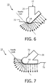
- step 54 the clinician inserts the needle next to the microconvex array 14 as shown in FIGURE 6
- step 56 the clinician observes the initial path of needle insertion in the image field scanned by the microconvex array.
- the next step 58 is to rotate the probe with the handle 20, bringing the linear array 16 into acoustic contact with the skin 70 as shown in FIGURE 7 .
- This rotation also is seen to bring the far end of the microconvex array out of acoustic contact with the skin. This may be done without losing the view of the needle, as at least a portion of the aperture of the microconvex and linear array elements is always in acoustic contact with the skin as the probe is rotated.
- the handle 20 is now above the linear array 16 as FIGURE 7 shows, enabling the clinician to press down with a force 72 to firmly press the linear array aperture into good acoustic contact with the skin 70.
- the continued insertion of the needle is beneath the linear array section of the probe aperture, enabling the linear array 16 to visualize continued insertion of the needle deeper into the body with good resolution and clarity until the tip of the needle reaches its intended target, as stated by step 60.
- the display format is dynamically adjusted during rotation of the probe so that greater tissue depths are always at the bottom of the display, thereby giving the clinician a consistent frame of reference.
- this is done by control of the manner in which the scan converter renders the image.
- the purpose of the scan converter is to convert the r- ⁇ coordinates of the receive beam scanlines into an image with x-y coordinates suitable for a raster display and in the appropriate sector, linear, or curved linear scan format.
- the scan converter is further controlled by an orientation signal which identifies the vertical orientation (up, down direction) of the image. There are several ways to accomplish this.
- an accelerometer 90 located in the probe 10 as shown in FIGURES 8a and 8b , which produces signals that measure a constant orientation direction such as the direction of gravitational force.
- the scan converter then renders the ultrasound image with its vertical direction aligned with the measured orientation direction.
- Conventionally accelerometers have been used in ultrasound probes to measure displacement for the reconstruction of 3D images, as described in US Pat. 5,529,070 (Augustine et al. )
- signals from accelerometers are processed over time to measure probe displacement, which is the second derivative of the acceleration signals.
- the gravitational force vectors are canceled in the processing algorithms. But it is the static gravitational force vector alone which can be used as an orientation signal in an implementation of the present invention.
- a second way to produce an orientation signal is by detection of the portion of the array 14, 16 which is acoustically coupled to the skinline at any point in time.
- the vertical image direction is then taken as a vector 100 normal to the center of the acoustically coupled portion of the array.
- FIGURE 8a shows the probe 10 being held at the time of needle insertion with most of the elements 14' of the microconvex array in contact with the skin.
- the elements of the linear array 16 are not in contact with the skinline at this time.
- a vector arrow 100 is shown drawn normal to the center of the microconvex array portion 14', and this vector direction is used for the image orientation signal.
- a third way to produce a suitable orientation signal is by image analysis, also known in the art as feature tracking. For instance the layers of skin, fat, and striated muscle immediately beneath the skin can be identified in the image and the horizontal orientation set to be in general alignment with these layers by an orientation signal.
- a second image analysis technique is to identify the pathological target of the needle procedure in the image, which may be done either manually or automatically. For example, the clinician can click on the target in the image prior to commencing needle insertion. The target anatomy is then rendered in the same location in each successive image frame, which may be done using image stabilization techniques. Ultrasonic image stabilization is well known, as described in US Pat. 6,589,176 (Jago et al.
- the image stabilization in an implementation of the present invention is preferably not done rigorously enough to preclude rotation, as that is the expected result of the probe motion. Center-to-center stabilization will be sufficient to produce a sequence of consistently useful images as the probe is rotated. Alternatively, the speckle characteristic of the identified target anatomy can be tracked from frame to frame to maintain the anatomy in the same location from frame to frame.
- FIGURES 9a, 9b, 9c, and 9d illustrate a number of methods for generating an orientation signal.
- FIGURE 9a illustrates a technique using an accelerometer in the probe.
- a suitable accelerometer for this purpose is a three-axis accelerometer such as those of the ADXL300 series of MEMS (micro electro-mechanical system) accelerometers available from Analog Devices, Inc. of Boston, MA.
- the signals of the three axes are received by an orientation processor in step 110. Samples of these three signals are respectively averaged over a sampling interval such as a few seconds to produce values v x , v y , and v z from the three axes.
- the three values are vectorially combined to produce the vertical acceleration vector v corresponding to gravity, which is nominally 9.81 meters/second and is in a direction straight up as shown in step 112.
- the vector direction of gravitational force indicated by arrow G in FIGURES 8a and 8b , is then used in the output orientation signal, step 114, to cause the scan converter to render the image with the indicated direction G as the vertical direction.
- the direction commonly referred to as "up" will always be at the top of the displayed image.
- FIGURE 9b illustrates an orientation signal identification process using acoustic contact between elements of the transducer array 14, 16 and the skin of the patient.
- Signals from all of the elements of the array are coupled to an orientation processor in step 120 where they are analyzed for acoustic ring-down in step 122.
- an ultrasound transducer element is not acoustically coupled to the skin, its echo response exhibits a distinctive ring-down artifact.
- a typical ring-down signal from an uncoupled transducer element is shown in Fig. 6 of US Pat. 5,517,994 (Burke et al. ) for instance.
- Elements acoustically coupled to the subject will in contradistinction receive a sequence of echo signals from tissue.
- the orientation processor algorithm identifies those elements which are acoustically coupled to the patient, identifies the center of the sequence of acoustically coupled elements and, from knowledge of the geometry of the array, then identifies the direction normal to this center.
- the orientation signal communicates this direction (arrow 100 in FIGURES 8a and 8b ) to the scan converter in step 124, which uses this direction as the vertical direction in the rendered images.
- the element coupling and arrow direction are constantly updated so that the vertical direction of the image is constantly refined during the needle insertion procedure.
- FIGURE 9c illustrates the production of an image orientation signal by image processing and feature tracking.
- a sequence of ultrasound images is received by the orientation processor which in this instance is an image processor.
- Analysis is performed in step 132 to locate known image features, such as the previously described superficial layers immediately beneath the skin or the target anatomy. Alternatively these image characteristics may be manually identified in an image.
- An identified characteristic is tracked and its orientation or image location is communicated to the scan converter in step 134, which renders the image characteristic consistently from image frame to image frame.
- FIGURE 9d A specific image analysis technique is illustrated in FIGURE 9d .
- the clinician will be closely watching the position of the needle as it enters the body and particularly its inclination toward the target anatomy.
- the method of FIGURE 9d assists the clinician in this effort by stabilizing the position of the needle in the images.
- Ultrasound images are received by an orientation processor at step 140, which detects echo signal reflections from a needle.
- Such echo signals are very distinctive as a needle is a highly specular reflector of ultrasound and the echo signals from a needle are very strong. See, e.g., US Pat. 6,951,542 (Greppi et al.
- FIGURE 10 An ultrasound system constructed in accordance with the principles of the present invention is shown in block diagram form in FIGURE 10 .
- the microconvex-linear array 14, 16 of a probe 10 is coupled to a beamformer 150, which causes elements of the array to transmit ultrasound waves and receive echo signals in response.
- the received echo signal are beamformed into scanlines of coherent echo signals by the beamformer.
- the echo signals are processed by a signal processor 152 which performs functions such as filtering, frequency or spatial compounding, harmonic separation, and quadrature demodulation.
- a detector 154 performs signal detection, amplitude detection in the case of B mode images and Doppler detection in the case of Doppler signals.
- the scanlines of echo signals are stored in a scanline memory 156 which may be a conventional digital memory device.
- the scanlines of echo signals are rendered in a desired image format of Cartesian coordinates by a scan converter 160, with the vertical axis of the image or the location of a specific image object determined by an orientation signal as described previously.
- the orientation signal is produced as described above by an orientation processor 170, which may comprise electronic hardware components, hardware controlled by software, or a microprocessor executing signal and/or image processing algorithms as described in conjunction with FIGURES 9a-9d .
- the orientation processor 170 is shown coupled to receive accelerometer signals and/or echo signals from the probe 10 for vertical vector analysis and/or acoustic coupling analysis as described in FIGURES 9a and 9b .
- the orientation processor 170 is also shown coupled to receive ultrasound images from an image processor 162 for execution of the image processing techniques for orientation signal production as described in conjunction with FIGURES 9c and 9d .
- the image processor 162 receives rendered ultrasound images from the scan converter 160 and applies the images to a monitor or display 164 for viewing by the clinician.
- the various embodiments described above and illustrated herein may be implemented in hardware, software or a combination thereof.
- the various embodiments and/or components for example, the modules, or components and controllers therein, also may be implemented as part of one or more computers or microprocessors.
- the computer or processor may include a computing device, an input device, a display unit and an interface, for example, for accessing the Internet.
- the computer or processor may include a microprocessor.
- the microprocessor may be connected to a communication bus, for example, to access a PACS system.
- the computer or processor may also include a memory.
- the memory may include Random Access Memory (RAM) and Read Only Memory (ROM).
- the computer or processor further may include a storage device, which may be a hard disk drive or a removable storage drive such as a floppy disk drive, optical disk drive, solid-state thumb drive, and the like.
- the storage device may also be other similar means for loading computer programs or other instructions into the computer or processor.
- the term "computer” or “module” or “processor” may include any processor-based or microprocessor-based system including systems using microcontrollers, reduced instruction set computers (RISC), ASICs, logic circuits, and any other circuit or processor capable of executing the functions described herein.
- the above examples are exemplary only, and are thus not intended to limit in any way the definition and/or meaning of these terms.
- the computer or processor executes a set of instructions that are stored in one or more storage elements, in order to process input data.
- the storage elements may also store data or other information as desired or needed.
- the storage element may be in the form of an information source or a physical memory element within a processing machine.
- the set of instructions may include various commands that instruct the computer or processor as a processing machine to perform specific operations such as the methods and processes of the various embodiments of the invention.
- the set of instructions may be in the form of a software program.
- the software may be in various forms such as system software or application software and which may be embodied as a tangible and non-transitory computer readable medium. Further, the software may be in the form of a collection of separate programs or modules, a program module within a larger program or a portion of a program module.
- the software also may include modular programming in the form of object-oriented programming.
- the processing of input data by the processing machine may be in response to operator commands, or in response to results of previous processing, or in response to a request made by another processing machine.
Claims (15)
- Ein Ultraschallsystem, das Folgendes umfasst:eine mikrokonvex-lineare Ultraschallsonde (10) mit einer Anordnung von mikrokonvexen Ultraschallelementen (14) und linearen Ultraschallelementen (16);einen Scan-Konverter (160), der angeschlossen ist, um Echosignale von der Ultraschallsonde zu erhalten und Ultraschallbilder im gewünschten Bildformat darzustellen, wobei die Echosignale für die aktiven Apertur-Oberflächen entlang der gesamten Anordnung von mikrokonvexen und linearen Elementen gewöhnliche Strahlen bilden, sodass ein fortlaufendes Bildfeld entlang der gesamten Anordnung von mikrokonvexen und linearen Elementen abgetastet wird;einen Ausrichtungsprozessor (170), der mindestens entweder an die Ultraschallsonde oder den Scan-Konverter angeschlossen ist, um ein Bildausrichtungssignal zu erzeugen, das mit dem Scan-Konverter verbunden ist; undeine Ultraschallbildanzeige (164), die angeschlossen ist, um die vom Scan-Konverter erstellten Bilder in der gewünschten Bildausrichtung anzuzeigen.
- Das Ultraschallsystem gemäß Anspruch 1, wobei die Ultraschallsonde (10) zudem einen Beschleunigungsmesser (90) umfasst, wobei der Ausrichtungsprozessor (170) zudem angeschlossen ist, um Signale vom Beschleunigungsmesser zu empfangen.
- Das Ultraschallsystem gemäß Anspruch 2, wobei der Ausrichtungsprozessor (170) zudem die Ausrichtung der Schwerkraft erkennt.
- Das Ultraschallsystem gemäß Anspruch 1, wobei die Ultraschallsonde (10) eine Anordnung von mikrokonvex-linearen Wandlern umfasst, wobei der Ausrichtungsprozessor (170) zudem angeschlossen ist, um Echosignale von den Wandlern zu empfangen.
- Das Ultraschallsystem gemäß Anspruch 4, wobei der Ausrichtungsprozessor (170) zudem Ring-Down-Signale von Elementen erkennt, die nicht akustisch an einem Objekt angeschlossen sind.
- Das Ultraschallsystem gemäß Anspruch 1, wobei der Ausrichtungsprozessor (170) zudem einen Ultraschallbildprozessor (162) umfasst.
- Das Ultraschallsystem gemäß Anspruch 6, wobei der Ausrichtungsprozessor (170) zudem ein bestimmtes Merkmal in einem Ultraschallbild erkennt.
- Das Ultraschallsystem gemäß Anspruch 7, wobei der Ausrichtungsprozessor (170) zudem ein bestimmtes Merkmal in einer Abfolge von Ultraschallbildern nachverfolgt.
- Das Ultraschallsystem gemäß Anspruch 8, wobei der Ausrichtungsprozessor (170) zudem das bestimmte Merkmal in einer Abfolge von Ultraschallbildern mithilfe von Speckle-Tracking nachverfolgt.
- Das Ultraschallsystem gemäß Anspruch 8, wobei der Ausrichtungsprozessor (170) zudem die Position des bestimmten Merkmals in der Abfolge von Ultraschallbildern stabilisiert.
- Das Ultraschallsystem gemäß Anspruch 7, wobei der Ausrichtungsprozessor (170) zudem Echosignale erkennt, die von einer Nadel zurückgegeben werden.
- Das Ultraschallsystem gemäß Anspruch 11, wobei der Ausrichtungsprozessor (170) zudem die Position der Nadel in einer Abfolge von Ultraschallbildern stabilisiert.
- Das Ultraschallsystem gemäß Anspruch 1, das zudem über einen Beamformer (150) verfügt, der angeschlossen ist, um Echosignale von einem Wandler einer Anordnung von Wandlern in der mikrokonvex-linearen Ultraschallsonde (10) zu empfangen.
- Das Ultraschallsystem gemäß Anspruch 13, das zudem einen am Beamformer angeschlossenen Detektor (154) umfasst.
- Das Ultraschallsystem gemäß Anspruch 14, das zudem einen am Detektor angeschlossenen Scanline-Speicher (156) umfasst.
Applications Claiming Priority (2)
| Application Number | Priority Date | Filing Date | Title |
|---|---|---|---|
| US201662350848P | 2016-06-16 | 2016-06-16 | |
| PCT/EP2017/064209 WO2017216078A1 (en) | 2016-06-16 | 2017-06-12 | Image orientation identification for an external microconvex-linear ultrasound probe |
Publications (2)
| Publication Number | Publication Date |
|---|---|
| EP3471619A1 EP3471619A1 (de) | 2019-04-24 |
| EP3471619B1 true EP3471619B1 (de) | 2020-08-05 |
Family
ID=59030967
Family Applications (1)
| Application Number | Title | Priority Date | Filing Date |
|---|---|---|---|
| EP17728866.9A Active EP3471619B1 (de) | 2016-06-16 | 2017-06-12 | Erkennung der bildausrichtung für eine externe mikrokonvex-lineare ultraschallsonde |
Country Status (5)
| Country | Link |
|---|---|
| US (1) | US20190223831A1 (de) |
| EP (1) | EP3471619B1 (de) |
| JP (1) | JP6873163B2 (de) |
| CN (1) | CN109310393B (de) |
| WO (1) | WO2017216078A1 (de) |
Families Citing this family (1)
| Publication number | Priority date | Publication date | Assignee | Title |
|---|---|---|---|---|
| JP7357441B2 (ja) * | 2018-06-15 | 2023-10-06 | フクダ電子株式会社 | 超音波プローブ |
Family Cites Families (18)
| Publication number | Priority date | Publication date | Assignee | Title |
|---|---|---|---|---|
| GB9025431D0 (en) | 1990-11-22 | 1991-01-09 | Advanced Tech Lab | Three dimensional ultrasonic imaging |
| JPH0595945A (ja) * | 1991-10-08 | 1993-04-20 | Toshiba Corp | 穿刺用超音波プローブ |
| US5469853A (en) * | 1992-12-11 | 1995-11-28 | Tetrad Corporation | Bendable ultrasonic probe and sheath for use therewith |
| US5517994A (en) | 1994-11-16 | 1996-05-21 | Advanced Technology Laboratories, Inc. | Self diagnostic ultrasonic imaging systems |
| JPH08229034A (ja) * | 1995-02-28 | 1996-09-10 | Shimadzu Corp | 超音波診断装置 |
| US6045508A (en) * | 1997-02-27 | 2000-04-04 | Acuson Corporation | Ultrasonic probe, system and method for two-dimensional imaging or three-dimensional reconstruction |
| US6102862A (en) * | 1998-10-02 | 2000-08-15 | Scimed Life Systems, Inc. | Adaptive cancellation of ring-down artifact in IVUS imaging |
| US6951542B2 (en) | 2002-06-26 | 2005-10-04 | Esaote S.P.A. | Method and apparatus for ultrasound imaging of a biopsy needle or the like during an ultrasound imaging examination |
| US6589176B2 (en) | 2001-12-05 | 2003-07-08 | Koninklijke Philips Electronics N.V. | Ultrasonic image stabilization system and method |
| JP4266611B2 (ja) * | 2002-10-15 | 2009-05-20 | オリンパス株式会社 | 超音波プローブ、超音波内視鏡、及び超音波診断装置 |
| JP5179083B2 (ja) * | 2007-03-29 | 2013-04-10 | ジーイー・メディカル・システムズ・グローバル・テクノロジー・カンパニー・エルエルシー | 超音波プローブおよび超音波撮像装置 |
| US8137278B2 (en) * | 2007-09-12 | 2012-03-20 | Sonosite, Inc. | System and method for spatial compounding using phased arrays |
| JP2009297384A (ja) * | 2008-06-17 | 2009-12-24 | Fujifilm Corp | 超音波診断装置及び超音波探触子 |
| US20100106023A1 (en) * | 2008-09-29 | 2010-04-29 | Kabushiki Kaisha Toshiba | Body cavity ultrasonic probe and ultrasonic diagnosis apparatus |
| JP2010214015A (ja) * | 2009-03-18 | 2010-09-30 | Fujifilm Corp | 超音波プローブ及び超音波診断装置 |
| CN102961166A (zh) * | 2011-08-31 | 2013-03-13 | 通用电气公司 | 用于检测和跟踪针的方法 |
| JP2014161444A (ja) * | 2013-02-22 | 2014-09-08 | Toshiba Corp | 超音波診断装置、医用画像処理装置及び制御プログラム |
| US20150182198A1 (en) * | 2013-12-27 | 2015-07-02 | General Electric Company | System and method for displaying ultrasound images |
-
2017
- 2017-06-12 US US16/306,963 patent/US20190223831A1/en not_active Abandoned
- 2017-06-12 EP EP17728866.9A patent/EP3471619B1/de active Active
- 2017-06-12 CN CN201780036749.3A patent/CN109310393B/zh active Active
- 2017-06-12 WO PCT/EP2017/064209 patent/WO2017216078A1/en unknown
- 2017-06-12 JP JP2018565054A patent/JP6873163B2/ja active Active
Also Published As
| Publication number | Publication date |
|---|---|
| US20190223831A1 (en) | 2019-07-25 |
| JP6873163B2 (ja) | 2021-05-19 |
| CN109310393B (zh) | 2022-04-08 |
| EP3471619A1 (de) | 2019-04-24 |
| JP2019517881A (ja) | 2019-06-27 |
| CN109310393A (zh) | 2019-02-05 |
| WO2017216078A1 (en) | 2017-12-21 |
Similar Documents
| Publication | Publication Date | Title |
|---|---|---|
| JP6462164B2 (ja) | 画像内の物体の向上された撮像のためのシステムおよび方法 | |
| KR101182880B1 (ko) | 영상 지시자를 제공하는 초음파 시스템 및 방법 | |
| JP5495593B2 (ja) | 超音波診断装置及び穿刺支援用制御プログラム | |
| EP3192053B1 (de) | Qualitätsmetrik für echokardiographische mehrtakterfassungen für unmittelbares benutzerfeedback | |
| US20220273258A1 (en) | Path tracking in ultrasound system for device tracking | |
| JPH04317641A (ja) | 超音波映像化装置 | |
| EP3749210B1 (de) | Multiparametrische gewebesteifigkeitsquantifizierung | |
| WO2015092628A1 (en) | Ultrasound imaging systems and methods for tracking locations of an invasive medical device | |
| US20210007714A1 (en) | Ultrasound system for shear wave imaging in three dimensions | |
| EP3515317B1 (de) | Ultraschallwandlerkachelregistrierung | |
| EP3471619B1 (de) | Erkennung der bildausrichtung für eine externe mikrokonvex-lineare ultraschallsonde | |
| EP3142560B1 (de) | Medizinisches bildverarbeitungssystem und verfahren dafür | |
| EP3367909B1 (de) | System zur 3d-ultraschallbildgebung für nervenblockadeanwendungen | |
| WO2017216365A1 (en) | External microconvex-linear ultrasound probe | |
| US20140088430A1 (en) | Ultrasonic image guidance of transcutaneous procedures | |
| KR101060351B1 (ko) | 탄성 영상을 형성하는 초음파 시스템 및 방법 |
Legal Events
| Date | Code | Title | Description |
|---|---|---|---|
| STAA | Information on the status of an ep patent application or granted ep patent |
Free format text: STATUS: UNKNOWN |
|
| STAA | Information on the status of an ep patent application or granted ep patent |
Free format text: STATUS: THE INTERNATIONAL PUBLICATION HAS BEEN MADE |
|
| PUAI | Public reference made under article 153(3) epc to a published international application that has entered the european phase |
Free format text: ORIGINAL CODE: 0009012 |
|
| STAA | Information on the status of an ep patent application or granted ep patent |
Free format text: STATUS: REQUEST FOR EXAMINATION WAS MADE |
|
| 17P | Request for examination filed |
Effective date: 20190116 |
|
| AK | Designated contracting states |
Kind code of ref document: A1 Designated state(s): AL AT BE BG CH CY CZ DE DK EE ES FI FR GB GR HR HU IE IS IT LI LT LU LV MC MK MT NL NO PL PT RO RS SE SI SK SM TR |
|
| AX | Request for extension of the european patent |
Extension state: BA ME |
|
| DAV | Request for validation of the european patent (deleted) | ||
| DAX | Request for extension of the european patent (deleted) | ||
| RAP1 | Party data changed (applicant data changed or rights of an application transferred) |
Owner name: KONINKLIJKE PHILIPS N.V. |
|
| GRAP | Despatch of communication of intention to grant a patent |
Free format text: ORIGINAL CODE: EPIDOSNIGR1 |
|
| STAA | Information on the status of an ep patent application or granted ep patent |
Free format text: STATUS: GRANT OF PATENT IS INTENDED |
|
| INTG | Intention to grant announced |
Effective date: 20200415 |
|
| GRAS | Grant fee paid |
Free format text: ORIGINAL CODE: EPIDOSNIGR3 |
|
| GRAA | (expected) grant |
Free format text: ORIGINAL CODE: 0009210 |
|
| STAA | Information on the status of an ep patent application or granted ep patent |
Free format text: STATUS: THE PATENT HAS BEEN GRANTED |
|
| AK | Designated contracting states |
Kind code of ref document: B1 Designated state(s): AL AT BE BG CH CY CZ DE DK EE ES FI FR GB GR HR HU IE IS IT LI LT LU LV MC MK MT NL NO PL PT RO RS SE SI SK SM TR |
|
| REG | Reference to a national code |
Ref country code: GB Ref legal event code: FG4D |
|
| REG | Reference to a national code |
Ref country code: CH Ref legal event code: EP |
|
| REG | Reference to a national code |
Ref country code: AT Ref legal event code: REF Ref document number: 1297584 Country of ref document: AT Kind code of ref document: T Effective date: 20200815 |
|
| REG | Reference to a national code |
Ref country code: DE Ref legal event code: R096 Ref document number: 602017021059 Country of ref document: DE |
|
| REG | Reference to a national code |
Ref country code: IE Ref legal event code: FG4D |
|
| REG | Reference to a national code |
Ref country code: DE Ref legal event code: R084 Ref document number: 602017021059 Country of ref document: DE |
|
| REG | Reference to a national code |
Ref country code: LT Ref legal event code: MG4D |
|
| REG | Reference to a national code |
Ref country code: GB Ref legal event code: 746 Effective date: 20201208 |
|
| REG | Reference to a national code |
Ref country code: NL Ref legal event code: MP Effective date: 20200805 |
|
| REG | Reference to a national code |
Ref country code: AT Ref legal event code: MK05 Ref document number: 1297584 Country of ref document: AT Kind code of ref document: T Effective date: 20200805 |
|
| PG25 | Lapsed in a contracting state [announced via postgrant information from national office to epo] |
Ref country code: FI Free format text: LAPSE BECAUSE OF FAILURE TO SUBMIT A TRANSLATION OF THE DESCRIPTION OR TO PAY THE FEE WITHIN THE PRESCRIBED TIME-LIMIT Effective date: 20200805 Ref country code: LT Free format text: LAPSE BECAUSE OF FAILURE TO SUBMIT A TRANSLATION OF THE DESCRIPTION OR TO PAY THE FEE WITHIN THE PRESCRIBED TIME-LIMIT Effective date: 20200805 Ref country code: SE Free format text: LAPSE BECAUSE OF FAILURE TO SUBMIT A TRANSLATION OF THE DESCRIPTION OR TO PAY THE FEE WITHIN THE PRESCRIBED TIME-LIMIT Effective date: 20200805 Ref country code: HR Free format text: LAPSE BECAUSE OF FAILURE TO SUBMIT A TRANSLATION OF THE DESCRIPTION OR TO PAY THE FEE WITHIN THE PRESCRIBED TIME-LIMIT Effective date: 20200805 Ref country code: PT Free format text: LAPSE BECAUSE OF FAILURE TO SUBMIT A TRANSLATION OF THE DESCRIPTION OR TO PAY THE FEE WITHIN THE PRESCRIBED TIME-LIMIT Effective date: 20201207 Ref country code: GR Free format text: LAPSE BECAUSE OF FAILURE TO SUBMIT A TRANSLATION OF THE DESCRIPTION OR TO PAY THE FEE WITHIN THE PRESCRIBED TIME-LIMIT Effective date: 20201106 Ref country code: ES Free format text: LAPSE BECAUSE OF FAILURE TO SUBMIT A TRANSLATION OF THE DESCRIPTION OR TO PAY THE FEE WITHIN THE PRESCRIBED TIME-LIMIT Effective date: 20200805 Ref country code: AT Free format text: LAPSE BECAUSE OF FAILURE TO SUBMIT A TRANSLATION OF THE DESCRIPTION OR TO PAY THE FEE WITHIN THE PRESCRIBED TIME-LIMIT Effective date: 20200805 Ref country code: NO Free format text: LAPSE BECAUSE OF FAILURE TO SUBMIT A TRANSLATION OF THE DESCRIPTION OR TO PAY THE FEE WITHIN THE PRESCRIBED TIME-LIMIT Effective date: 20201105 Ref country code: BG Free format text: LAPSE BECAUSE OF FAILURE TO SUBMIT A TRANSLATION OF THE DESCRIPTION OR TO PAY THE FEE WITHIN THE PRESCRIBED TIME-LIMIT Effective date: 20201105 |
|
| PG25 | Lapsed in a contracting state [announced via postgrant information from national office to epo] |
Ref country code: PL Free format text: LAPSE BECAUSE OF FAILURE TO SUBMIT A TRANSLATION OF THE DESCRIPTION OR TO PAY THE FEE WITHIN THE PRESCRIBED TIME-LIMIT Effective date: 20200805 Ref country code: RS Free format text: LAPSE BECAUSE OF FAILURE TO SUBMIT A TRANSLATION OF THE DESCRIPTION OR TO PAY THE FEE WITHIN THE PRESCRIBED TIME-LIMIT Effective date: 20200805 Ref country code: NL Free format text: LAPSE BECAUSE OF FAILURE TO SUBMIT A TRANSLATION OF THE DESCRIPTION OR TO PAY THE FEE WITHIN THE PRESCRIBED TIME-LIMIT Effective date: 20200805 Ref country code: LV Free format text: LAPSE BECAUSE OF FAILURE TO SUBMIT A TRANSLATION OF THE DESCRIPTION OR TO PAY THE FEE WITHIN THE PRESCRIBED TIME-LIMIT Effective date: 20200805 Ref country code: IS Free format text: LAPSE BECAUSE OF FAILURE TO SUBMIT A TRANSLATION OF THE DESCRIPTION OR TO PAY THE FEE WITHIN THE PRESCRIBED TIME-LIMIT Effective date: 20201205 |
|
| PG25 | Lapsed in a contracting state [announced via postgrant information from national office to epo] |
Ref country code: RO Free format text: LAPSE BECAUSE OF FAILURE TO SUBMIT A TRANSLATION OF THE DESCRIPTION OR TO PAY THE FEE WITHIN THE PRESCRIBED TIME-LIMIT Effective date: 20200805 Ref country code: CZ Free format text: LAPSE BECAUSE OF FAILURE TO SUBMIT A TRANSLATION OF THE DESCRIPTION OR TO PAY THE FEE WITHIN THE PRESCRIBED TIME-LIMIT Effective date: 20200805 Ref country code: DK Free format text: LAPSE BECAUSE OF FAILURE TO SUBMIT A TRANSLATION OF THE DESCRIPTION OR TO PAY THE FEE WITHIN THE PRESCRIBED TIME-LIMIT Effective date: 20200805 Ref country code: EE Free format text: LAPSE BECAUSE OF FAILURE TO SUBMIT A TRANSLATION OF THE DESCRIPTION OR TO PAY THE FEE WITHIN THE PRESCRIBED TIME-LIMIT Effective date: 20200805 Ref country code: SM Free format text: LAPSE BECAUSE OF FAILURE TO SUBMIT A TRANSLATION OF THE DESCRIPTION OR TO PAY THE FEE WITHIN THE PRESCRIBED TIME-LIMIT Effective date: 20200805 |
|
| REG | Reference to a national code |
Ref country code: DE Ref legal event code: R097 Ref document number: 602017021059 Country of ref document: DE |
|
| PG25 | Lapsed in a contracting state [announced via postgrant information from national office to epo] |
Ref country code: AL Free format text: LAPSE BECAUSE OF FAILURE TO SUBMIT A TRANSLATION OF THE DESCRIPTION OR TO PAY THE FEE WITHIN THE PRESCRIBED TIME-LIMIT Effective date: 20200805 |
|
| PLBE | No opposition filed within time limit |
Free format text: ORIGINAL CODE: 0009261 |
|
| STAA | Information on the status of an ep patent application or granted ep patent |
Free format text: STATUS: NO OPPOSITION FILED WITHIN TIME LIMIT |
|
| PG25 | Lapsed in a contracting state [announced via postgrant information from national office to epo] |
Ref country code: SK Free format text: LAPSE BECAUSE OF FAILURE TO SUBMIT A TRANSLATION OF THE DESCRIPTION OR TO PAY THE FEE WITHIN THE PRESCRIBED TIME-LIMIT Effective date: 20200805 |
|
| 26N | No opposition filed |
Effective date: 20210507 |
|
| PG25 | Lapsed in a contracting state [announced via postgrant information from national office to epo] |
Ref country code: IT Free format text: LAPSE BECAUSE OF FAILURE TO SUBMIT A TRANSLATION OF THE DESCRIPTION OR TO PAY THE FEE WITHIN THE PRESCRIBED TIME-LIMIT Effective date: 20200805 |
|
| PG25 | Lapsed in a contracting state [announced via postgrant information from national office to epo] |
Ref country code: SI Free format text: LAPSE BECAUSE OF FAILURE TO SUBMIT A TRANSLATION OF THE DESCRIPTION OR TO PAY THE FEE WITHIN THE PRESCRIBED TIME-LIMIT Effective date: 20200805 |
|
| PG25 | Lapsed in a contracting state [announced via postgrant information from national office to epo] |
Ref country code: MC Free format text: LAPSE BECAUSE OF FAILURE TO SUBMIT A TRANSLATION OF THE DESCRIPTION OR TO PAY THE FEE WITHIN THE PRESCRIBED TIME-LIMIT Effective date: 20200805 |
|
| REG | Reference to a national code |
Ref country code: CH Ref legal event code: PL |
|
| REG | Reference to a national code |
Ref country code: BE Ref legal event code: MM Effective date: 20210630 |
|
| PG25 | Lapsed in a contracting state [announced via postgrant information from national office to epo] |
Ref country code: LU Free format text: LAPSE BECAUSE OF NON-PAYMENT OF DUE FEES Effective date: 20210612 |
|
| PG25 | Lapsed in a contracting state [announced via postgrant information from national office to epo] |
Ref country code: LI Free format text: LAPSE BECAUSE OF NON-PAYMENT OF DUE FEES Effective date: 20210630 Ref country code: IE Free format text: LAPSE BECAUSE OF NON-PAYMENT OF DUE FEES Effective date: 20210612 Ref country code: CH Free format text: LAPSE BECAUSE OF NON-PAYMENT OF DUE FEES Effective date: 20210630 |
|
| PG25 | Lapsed in a contracting state [announced via postgrant information from national office to epo] |
Ref country code: FR Free format text: LAPSE BECAUSE OF NON-PAYMENT OF DUE FEES Effective date: 20210630 |
|
| PG25 | Lapsed in a contracting state [announced via postgrant information from national office to epo] |
Ref country code: BE Free format text: LAPSE BECAUSE OF NON-PAYMENT OF DUE FEES Effective date: 20210630 |
|
| PGFP | Annual fee paid to national office [announced via postgrant information from national office to epo] |
Ref country code: GB Payment date: 20220621 Year of fee payment: 6 |
|
| PGFP | Annual fee paid to national office [announced via postgrant information from national office to epo] |
Ref country code: DE Payment date: 20220628 Year of fee payment: 6 |
|
| PG25 | Lapsed in a contracting state [announced via postgrant information from national office to epo] |
Ref country code: CY Free format text: LAPSE BECAUSE OF FAILURE TO SUBMIT A TRANSLATION OF THE DESCRIPTION OR TO PAY THE FEE WITHIN THE PRESCRIBED TIME-LIMIT Effective date: 20200805 |
|
| PG25 | Lapsed in a contracting state [announced via postgrant information from national office to epo] |
Ref country code: HU Free format text: LAPSE BECAUSE OF FAILURE TO SUBMIT A TRANSLATION OF THE DESCRIPTION OR TO PAY THE FEE WITHIN THE PRESCRIBED TIME-LIMIT; INVALID AB INITIO Effective date: 20170612 |
|
| REG | Reference to a national code |
Ref country code: DE Ref legal event code: R119 Ref document number: 602017021059 Country of ref document: DE |
|
| GBPC | Gb: european patent ceased through non-payment of renewal fee |
Effective date: 20230612 |