EP3470775A1 - Method and measuring assembly for measuring layer thickness and sound wave speed in single-layered or multilayered samples by means of ultrasound without a priori knowledge of the other variable - Google Patents
Method and measuring assembly for measuring layer thickness and sound wave speed in single-layered or multilayered samples by means of ultrasound without a priori knowledge of the other variable Download PDFInfo
- Publication number
- EP3470775A1 EP3470775A1 EP17195986.9A EP17195986A EP3470775A1 EP 3470775 A1 EP3470775 A1 EP 3470775A1 EP 17195986 A EP17195986 A EP 17195986A EP 3470775 A1 EP3470775 A1 EP 3470775A1
- Authority
- EP
- European Patent Office
- Prior art keywords
- sound
- sample
- transducer
- layer
- coupling body
- Prior art date
- Legal status (The legal status is an assumption and is not a legal conclusion. Google has not performed a legal analysis and makes no representation as to the accuracy of the status listed.)
- Granted
Links
- 238000000034 method Methods 0.000 title claims abstract description 29
- 238000002604 ultrasonography Methods 0.000 title claims description 23
- 239000010410 layer Substances 0.000 claims description 93
- 230000008878 coupling Effects 0.000 claims description 55
- 238000010168 coupling process Methods 0.000 claims description 55
- 238000005859 coupling reaction Methods 0.000 claims description 55
- 238000005311 autocorrelation function Methods 0.000 claims description 12
- 229910000679 solder Inorganic materials 0.000 claims description 6
- 239000002356 single layer Substances 0.000 claims description 4
- 238000003491 array Methods 0.000 claims description 3
- 238000004364 calculation method Methods 0.000 claims description 2
- 238000005259 measurement Methods 0.000 abstract description 45
- 238000000576 coating method Methods 0.000 abstract description 3
- 239000000523 sample Substances 0.000 description 129
- 229910000831 Steel Inorganic materials 0.000 description 13
- 239000010959 steel Substances 0.000 description 13
- 239000004033 plastic Substances 0.000 description 4
- 229920003023 plastic Polymers 0.000 description 4
- 230000002123 temporal effect Effects 0.000 description 4
- 230000005540 biological transmission Effects 0.000 description 3
- 238000011156 evaluation Methods 0.000 description 3
- 239000000463 material Substances 0.000 description 3
- 238000001208 nuclear magnetic resonance pulse sequence Methods 0.000 description 3
- 239000007822 coupling agent Substances 0.000 description 2
- 230000003111 delayed effect Effects 0.000 description 2
- 238000002592 echocardiography Methods 0.000 description 2
- XLYOFNOQVPJJNP-UHFFFAOYSA-N water Substances O XLYOFNOQVPJJNP-UHFFFAOYSA-N 0.000 description 2
- 229910001018 Cast iron Inorganic materials 0.000 description 1
- 239000004696 Poly ether ether ketone Substances 0.000 description 1
- 239000004734 Polyphenylene sulfide Substances 0.000 description 1
- 229920000491 Polyphenylsulfone Polymers 0.000 description 1
- 230000002238 attenuated effect Effects 0.000 description 1
- 230000008859 change Effects 0.000 description 1
- 239000011248 coating agent Substances 0.000 description 1
- 238000009675 coating thickness measurement Methods 0.000 description 1
- 238000010276 construction Methods 0.000 description 1
- 239000006185 dispersion Substances 0.000 description 1
- 229920006351 engineering plastic Polymers 0.000 description 1
- 230000005284 excitation Effects 0.000 description 1
- 238000007654 immersion Methods 0.000 description 1
- 239000007788 liquid Substances 0.000 description 1
- 229910052751 metal Inorganic materials 0.000 description 1
- 239000002184 metal Substances 0.000 description 1
- 150000002739 metals Chemical class 0.000 description 1
- 238000009659 non-destructive testing Methods 0.000 description 1
- 239000006223 plastic coating Substances 0.000 description 1
- 229920002530 polyetherether ketone Polymers 0.000 description 1
- 229920000069 polyphenylene sulfide Polymers 0.000 description 1
- 230000008569 process Effects 0.000 description 1
- 230000009467 reduction Effects 0.000 description 1
Images


Classifications
-
- G—PHYSICS
- G01—MEASURING; TESTING
- G01F—MEASURING VOLUME, VOLUME FLOW, MASS FLOW OR LIQUID LEVEL; METERING BY VOLUME
- G01F1/00—Measuring the volume flow or mass flow of fluid or fluent solid material wherein the fluid passes through a meter in a continuous flow
- G01F1/66—Measuring the volume flow or mass flow of fluid or fluent solid material wherein the fluid passes through a meter in a continuous flow by measuring frequency, phase shift or propagation time of electromagnetic or other waves, e.g. using ultrasonic flowmeters
- G01F1/667—Arrangements of transducers for ultrasonic flowmeters; Circuits for operating ultrasonic flowmeters
-
- G—PHYSICS
- G01—MEASURING; TESTING
- G01B—MEASURING LENGTH, THICKNESS OR SIMILAR LINEAR DIMENSIONS; MEASURING ANGLES; MEASURING AREAS; MEASURING IRREGULARITIES OF SURFACES OR CONTOURS
- G01B17/00—Measuring arrangements characterised by the use of infrasonic, sonic or ultrasonic vibrations
- G01B17/02—Measuring arrangements characterised by the use of infrasonic, sonic or ultrasonic vibrations for measuring thickness
- G01B17/025—Measuring arrangements characterised by the use of infrasonic, sonic or ultrasonic vibrations for measuring thickness for measuring thickness of coating
-
- G—PHYSICS
- G01—MEASURING; TESTING
- G01F—MEASURING VOLUME, VOLUME FLOW, MASS FLOW OR LIQUID LEVEL; METERING BY VOLUME
- G01F1/00—Measuring the volume flow or mass flow of fluid or fluent solid material wherein the fluid passes through a meter in a continuous flow
- G01F1/66—Measuring the volume flow or mass flow of fluid or fluent solid material wherein the fluid passes through a meter in a continuous flow by measuring frequency, phase shift or propagation time of electromagnetic or other waves, e.g. using ultrasonic flowmeters
- G01F1/663—Measuring the volume flow or mass flow of fluid or fluent solid material wherein the fluid passes through a meter in a continuous flow by measuring frequency, phase shift or propagation time of electromagnetic or other waves, e.g. using ultrasonic flowmeters by measuring Doppler frequency shift
-
- G—PHYSICS
- G01—MEASURING; TESTING
- G01N—INVESTIGATING OR ANALYSING MATERIALS BY DETERMINING THEIR CHEMICAL OR PHYSICAL PROPERTIES
- G01N29/00—Investigating or analysing materials by the use of ultrasonic, sonic or infrasonic waves; Visualisation of the interior of objects by transmitting ultrasonic or sonic waves through the object
- G01N29/04—Analysing solids
- G01N29/041—Analysing solids on the surface of the material, e.g. using Lamb, Rayleigh or shear waves
-
- G—PHYSICS
- G01—MEASURING; TESTING
- G01N—INVESTIGATING OR ANALYSING MATERIALS BY DETERMINING THEIR CHEMICAL OR PHYSICAL PROPERTIES
- G01N29/00—Investigating or analysing materials by the use of ultrasonic, sonic or infrasonic waves; Visualisation of the interior of objects by transmitting ultrasonic or sonic waves through the object
- G01N29/04—Analysing solids
- G01N29/07—Analysing solids by measuring propagation velocity or propagation time of acoustic waves
-
- G—PHYSICS
- G01—MEASURING; TESTING
- G01N—INVESTIGATING OR ANALYSING MATERIALS BY DETERMINING THEIR CHEMICAL OR PHYSICAL PROPERTIES
- G01N2291/00—Indexing codes associated with group G01N29/00
- G01N2291/01—Indexing codes associated with the measuring variable
- G01N2291/011—Velocity or travel time
-
- G—PHYSICS
- G01—MEASURING; TESTING
- G01N—INVESTIGATING OR ANALYSING MATERIALS BY DETERMINING THEIR CHEMICAL OR PHYSICAL PROPERTIES
- G01N2291/00—Indexing codes associated with group G01N29/00
- G01N2291/02—Indexing codes associated with the analysed material
- G01N2291/028—Material parameters
- G01N2291/02854—Length, thickness
-
- G—PHYSICS
- G01—MEASURING; TESTING
- G01N—INVESTIGATING OR ANALYSING MATERIALS BY DETERMINING THEIR CHEMICAL OR PHYSICAL PROPERTIES
- G01N2291/00—Indexing codes associated with group G01N29/00
- G01N2291/04—Wave modes and trajectories
- G01N2291/044—Internal reflections (echoes), e.g. on walls or defects
-
- G—PHYSICS
- G01—MEASURING; TESTING
- G01N—INVESTIGATING OR ANALYSING MATERIALS BY DETERMINING THEIR CHEMICAL OR PHYSICAL PROPERTIES
- G01N2291/00—Indexing codes associated with group G01N29/00
- G01N2291/04—Wave modes and trajectories
- G01N2291/056—Angular incidence, angular propagation
-
- G—PHYSICS
- G01—MEASURING; TESTING
- G01N—INVESTIGATING OR ANALYSING MATERIALS BY DETERMINING THEIR CHEMICAL OR PHYSICAL PROPERTIES
- G01N2291/00—Indexing codes associated with group G01N29/00
- G01N2291/10—Number of transducers
- G01N2291/105—Number of transducers two or more emitters, two or more receivers
Definitions
- the sound paths are generated by arranging at least one coupling body with at least two sound transducers on the surface of the single-layer or multi-layered sample.
- the sound transducers transmit the ultrasound signals at different angles to the sample surface on the two different sound paths through the coupling body into the sample and receive the reflected ultrasound signals again.
- Each sound path is traversed at least once by a signal of the same speed of sound in the layer.
- the formulas (1.1) and (1.2) are used to calculate the layer thickness and the speed of sound.
- the arrival time of the respective signal component at the receiver is delayed by the transit time ⁇ t 1 or ⁇ t 2 .
- the time interval of the incoming signal components (“echo time interval") within the ultrasonic signal via the sound path S 1 or S 2 is ⁇ t 1 or ⁇ t 2.
- the transit time ⁇ t 1 or ⁇ t 2 is determined by the layer thickness w of the sample 1 , the speed of sound c in the sample 1, the speed of sound c ⁇ in the coupling body 2 and the angle of incidence ⁇ 1 or ⁇ 2 determined.
Abstract
Diese Erfindung befasst sich mit dem Messen der Wandstärke von Rohren, Behältern oder Platten (im Folgenden als Probe bezeichnet) bei denen die Innen- bzw. Unterseite nicht zugänglich ist. Außerdem befasst sich die Erfindung mit der Messung der Schichtdicke von Beschichtungen oder Auskleidungen dieser Proben. Es werden spezielle Messanordnungen mittels Ultraschallsender- und Empfänger in Pitch-Catch und Puls-Echo-Konfiguration offengelegt sowie das zugehöriges Verfahren zur Bestimmung der Wandstärke ohne vorherige Kenntnis der Schallgeschwindigkeit in der Probe. Die Aufgabe der Erfindung ist es, die Wandstärke einer Probe (z.B. Rohrwand, Behälterwand oder Platte) unabhängig von der Kenntnis der Schallgeschwindigkeit dieser Probe zu messen. Eine weitere Aufgabe besteht in der Messung einzelner Schichtdicken eines Mehrschichtsystems (z.B. Rohrwand mit Beschichtung oder Auskleidung) ohne vorherige Kenntnis ihrer Schallgeschwindigkeiten. Das Verfahren und die Messanordnung ermöglichen es, die Wandstärke unabhängig von der Kenntnis der Schallgeschwindigkeit der Probe (z.B. Rohrwand, Behälterwand oder Platte) zu messen. Dies führt zu einer verringerten Messunsicherheit der Wandstärke und Innendurchmesser des Rohres und somit zu einer verringerten Messunsicherheit eines Clamp-On-Ultraschalldurchflussmessgerätes.This invention is concerned with measuring the wall thickness of pipes, containers or plates (hereinafter referred to as sample) in which the inside or bottom is not accessible. In addition, the invention is concerned with the measurement of the layer thickness of coatings or linings of these samples. Special measuring arrangements are disclosed by ultrasonic transmitter and receiver in pitch-catch and pulse-echo configuration and the associated method for determining the wall thickness without prior knowledge of the speed of sound in the sample. The object of the invention is to measure the wall thickness of a sample (e.g., pipe wall, vessel wall or plate) independently of the knowledge of the speed of sound of that sample. Another object is to measure individual layer thicknesses of a multi-layer system (e.g., coated or lined pipe wall) without prior knowledge of their sonic velocities. The method and the measuring arrangement make it possible to measure the wall thickness independently of the knowledge of the speed of sound of the sample (for example, pipe wall, vessel wall or plate). This leads to a reduced measurement uncertainty of the wall thickness and inner diameter of the tube and thus to a reduced measurement uncertainty of a clamp-on ultrasonic flowmeter.
Description
Diese Erfindung befasst sich mit dem Messen der Wandstärke von Rohren, Behältern oder Platten (im Folgenden als Probe bezeichnet) bei denen die Innen- bzw. Unterseite nicht zugänglich ist. Außerdem befasst sich die Erfindung mit der Messung der Schichtdicke von Beschichtungen oder Auskleidungen dieser Proben. Es werden spezielle Messanordnungen mittels Ultraschallsender- und Empfänger in Pitch-Catch und Puls-Echo-Konfiguration offengelegt sowie das zugehörige Verfahren zur Bestimmung der Wandstärke ohne vorherige Kenntnis der Schallgeschwindigkeit in der Probe.This invention is concerned with measuring the wall thickness of pipes, containers or plates (hereinafter referred to as sample) in which the inside or bottom is not accessible. In addition, the invention is concerned with the measurement of the layer thickness of coatings or linings of these samples. Special measuring arrangements are disclosed by means of ultrasonic transmitters and receivers in pitch-catch and pulse-echo configuration as well as the associated method for determining the wall thickness without prior knowledge of the speed of sound in the sample.
Die Notwendigkeit der Messung von Wandstärken ohne Zugang zur Innenseite ergibt sich beispielsweise in der Clamp-On-Ultraschalldurchflussmessung, bei welcher der Durchflusssensor auf ein bestehendes Rohr unbekannter Wandstärke geschnallt wird. Aber auch in der zerstörungsfreien Prüfung, z.B. zur Bestimmung der Druckfestigkeit von Behältern, ist die Messung von Wandstärken ohne Zugang zum Innenraum notwendig.The necessity of measuring wall thicknesses without access to the inside arises, for example, in the clamp-on ultrasonic flow measurement, in which the flow sensor is strapped onto an existing pipe of unknown wall thickness. But also in non-destructive testing, e.g. To determine the pressure resistance of containers, the measurement of wall thickness without access to the interior is necessary.
Die Genauigkeit von Clamp-On-Ultraschalldurchflussmessungen wird wesentlich durch die Unbestimmtheit des Rohrinnendurchmessers beeinflusst. Der Außendurchmesser eines Rohres kann einfach und genau mit einem Maßband gemessen werden. Um aus dem Außendurchmesser den Innendurchmesser zu errechnen, muss die Wandstärke des Rohres bekannt sein. Ein Fehler in der Wandstärkenbestimmung setzt sich letztendlich im Messfehler des Volumenstromes fort. Daher muss die Wandstärkenbestimmung so präzise wie möglich erfolgen. Aufgrund der Eingriffsfreiheit einer Clamp-on Durchflussmessung kann nur in seltenen Fällen die Wandstärke oder der Innendurchmesser mechanisch mit einer Mikrometerschraube oder Messschieber vermessen werden.The accuracy of clamp-on ultrasonic flow measurements is significantly affected by the indeterminacy of the tube internal diameter. The outer diameter of a pipe can be easily and accurately measured with a tape measure. In order to calculate the inner diameter from the outer diameter, the wall thickness of the pipe must be known. An error in the wall thickness determination is ultimately continued in the measurement error of the volume flow. Therefore, the must Wall thickness determination as precise as possible. Due to the freedom of movement of a clamp-on flow measurement, only in rare cases can the wall thickness or the inside diameter be measured mechanically with a micrometer screw or calliper.
Dem Stand der Technik entspricht die Messung der Wandstärke mit einem Ultraschallwanddickenmesser (WDM) im Puls-Echo-Verfahren wahlweise mit einem Schallwandlerelement (Sender und Empfänger sind identisches Element) oder mit zwei Schallwandlerelementen (Pitch-Catch Konfiguration). Bei diesem Verfahren wird ein Ultraschallpuls senkrecht zur Probenoberfläche in die Probe gesendet. Der Puls wird mehrfach in der Probe (Rohr- oder Behälterwandung, Platte) reflektiert. Jedes Echo wird vom Empfänger des Ultraschallwanddickenmessers aufgenommen. Aus dem Pulsabstand innerhalb der Echofolgen und mittels Kenntnis der Schallgeschwindigkeit der Probe kann dann die Wandstärke bestimmt werden. Um ein ausreichend genaues Ergebnis zu erhalten, muss die Schallgeschwindigkeit α-priori bekannt sein. Im Regelfall wird nur anhand grober Schätzung des Materials und anhand tabellierter Werte die Schallgeschwindigkeit geschätzt. Im Fall von Stahlproben kann aufgrund der Streuung der Schallgeschwindigkeiten verschiedener Stahlsorten die Schätzung 2% neben dem wahren Wert liegen. Temperaturbedingte Abweichungen der Rohrwandschallgeschwindigkeit werden gar nicht berücksichtigt (100 °C Temperaturunterschied führen zu etwa 1 % Schallgeschwindigkeitsfehler). Bei von Stahl abweichenden Materialien wie Gusseisen oder Kunststoffen kann der Schätzfehler weitaus höher liegen. Fehlerhafte Abschätzungen der Schallgeschwindigkeiten setzen sich direkt als Messfehler der Wandstärke fort. Betrachtet man diese Messunsicherheit in der Clamp-On Durchflussmessung, so führt bei großen Rohren (z.B. DN1000, 25 mm Wandstärke) eine Fehlschätzung von 2% der Rohrwandstärke zu einem Durchflussmessfehler von 0,2%. Bei kleinen und dickwandigen Rohren (z.B. 4" SCH 120) wächst der Fehler der Durchflussmessung auf 1%.The state of the art corresponds to the measurement of the wall thickness with an ultrasonic wall thickness gauge (WDM) in the pulse-echo method optionally with a sound transducer element (transmitter and receiver are identical element) or with two sound transducer elements (pitch-catch configuration). In this method, an ultrasonic pulse is sent perpendicular to the sample surface in the sample. The pulse is reflected several times in the sample (tube or container wall, plate). Each echo is picked up by the receiver of the ultrasonic thickness gauge. From the pulse distance within the Echofolgen and by knowing the speed of sound of the sample, the wall thickness can then be determined. In order to obtain a sufficiently accurate result, the sound velocity must be known α-priori. As a rule, the speed of sound is estimated only on the basis of a rough estimate of the material and tabulated values. In the case of steel samples, due to the dispersion of the velocities of different grades of steel, the estimate may be 2% off the true value. Temperature-related deviations of the pipe wall sound velocity are not considered at all (100 ° C temperature difference leads to about 1% speed error). For materials other than steel, such as cast iron or plastics, the estimation error can be much higher. Faulty estimates of the velocities of sound continue directly as measurement errors of the wall thickness. Considering this measurement uncertainty in the clamp-on flow measurement, for large pipes (eg DN1000, 25 mm wall thickness) a miscalculation of 2% of the pipe wall thickness leads to a flow measurement error of 0.2%. For small and thick-walled pipes (eg 4 "SCH 120) the flow measurement error increases to 1%.
Aus dem Patent
Verwendet man einen konventionellen Wanddickenmesser (WDM) auf einem beschichteten oder ausgekleideten Rohr oder für ein Mehrschichtsystem, so überlagern sich im allgemeinen Echofolgen aus jeder einzelnen Schicht, so dass diese nicht mehr ohne weiteres zur Wandstärkenbestimmung auswertbar sind. Im Falle spezieller Schichtdicken- und Schallgeschwindigkeitsverhältnisse der einzelnen Schichten können die Echofolgen zwar ausgewertet werden (z.B. dünne Kunststoffbeschichtung auf einer dicken Stahlrohrwand), aber ohne vorherige Kenntnis der Schallgeschwindigkeiten der einzelnen Schichten können nach dem Stand der Technik die einzelnen Schichtdicken nicht bestimmt werden.If a conventional wall thickness gauge (WDM) is used on a coated or lined tube or for a multilayer system, echo sequences from each individual layer are generally superposed, so that they can no longer be readily evaluated for wall thickness determination. Although in the case of specific layer thickness and sound velocity ratios of the individual layers, the echo sequences can be evaluated (for example thin plastic coating on a thick steel tube wall), but without prior knowledge of the velocities of the individual layers, the individual layer thicknesses can not be determined in the prior art.
Zur Vermessung verborgener Schichten oder aber von Mehrschichtsystemen stellen die Patente
Die Aufgabe der Erfindung ist es, die Wandstärke einer Probe (z.B. Rohrwand, Behälterwand oder Platte) unabhängig von der Kenntnis der Schallgeschwindigkeit dieser Probe zu messen. Eine weitere Aufgabe besteht in der Messung der Dicke einzelner Schichten eines Mehrschichtsystems (z.B. Rohrwand mit Beschichtung oder Auskleidung) ohne vorherige Kenntnis ihrer Schallgeschwindigkeiten.The object of the invention is to measure the wall thickness of a sample (e.g., pipe wall, vessel wall or plate) independently of the knowledge of the speed of sound of that sample. Another object is to measure the thickness of individual layers of a multi-layer system (e.g., coated or lined pipe wall) without prior knowledge of their sonic velocities.
Nachfolgend werden ein Verfahren und eine Messanordnung beschrieben, die es ermöglichen, die Wandstärke unabhängig von der Kenntnis der Schallgeschwindigkeit der Probe (z.B. Rohrwand, Behälterwand oder Platte) zu messen. Dies führt zu einer verringerten Messunsicherheit der Wandstärke und Innendurchmesser des Rohres und somit zu einer verringerten Messunsicherheit eines Clamp-On-Ultraschalldurchflussmessgerätes. Durch das Verfahren können einzelne Schichtdicken eines Mehrschichtsystems (z.B. Rohrwand mit Beschichtung oder Auskleidung) ohne vorherige Kenntnis ihrer Schallgeschwindigkeiten gemessen werden.In the following, a method and a measuring arrangement are described which make it possible to measure the wall thickness independently of the knowledge of the speed of sound of the sample (for example, pipe wall, container wall or plate). This leads to a reduced measurement uncertainty of the wall thickness and inner diameter of the tube and thus to a reduced measurement uncertainty of a clamp-on ultrasonic flowmeter. By the method, individual layer thicknesses of a multi-layer system (e.g., coated or lined pipe wall) can be measured without prior knowledge of their sound velocities.
Erfindungsgemäß erfolgt die Messung von Schichtdicke und Schallgeschwindigkeit wenigstens einer Schicht in einer ein- oder mehrlagigen Probe mittels Ultraschall durch Messung von Laufzeiten von Ultraschallsignalen auf wenigstens zwei verschiedenen Schallwegen durch die Probe. Die Schallwege laufen dazu unter verschiedenen Winkeln mit der gleichen Schallgeschwindigkeit in derselben Schicht der Probe.According to the invention, the measurement of the layer thickness and the speed of sound of at least one layer in a monolayer or multilayer sample is carried out by means of ultrasound by measuring transit times of ultrasound signals on at least two different sound paths through the sample. The sound paths run under different Angle at the same speed of sound in the same layer of the sample.
Die Schallwege werden erzeugt, indem auf der Oberfläche der ein- oder mehrlagigen Probe wenigstens ein Koppelkörper mit wenigstens zwei Schallwandlern angeordnet. Die Schallwandler senden die Ultraschallsignale unter verschiedenen Winkeln zur Probenoberfläche auf den zwei verschiedenen Schallwegen durch den Koppelkörper in die Probe und empfangen die reflektierten Ultraschallsignale wieder. Jeder Schallweg wird mindestens einmal von einem Signal mit einer gleich großen Schallgeschwindigkeit in der Schicht durchlaufen. Mit Hilfe von Der Formeln (1.1) und (1.2) erfolgt eine Berechnung der Schichtdicke und der Schallgeschwindigkeit.The sound paths are generated by arranging at least one coupling body with at least two sound transducers on the surface of the single-layer or multi-layered sample. The sound transducers transmit the ultrasound signals at different angles to the sample surface on the two different sound paths through the coupling body into the sample and receive the reflected ultrasound signals again. Each sound path is traversed at least once by a signal of the same speed of sound in the layer. The formulas (1.1) and (1.2) are used to calculate the layer thickness and the speed of sound.
Durch Messanordnungen mit verschiedenen Einstrahlwinkeln werden verschiedene Laufzeiten in der Probe durch Ausmessen der Pulsabstände innerhalb einer Echofolge bestimmt. Die erste Laufzeit berechnet sich als Position eines ersten Nebenmaximums einer Autokorrelationsfunktion einer Echofolge, wobei die Echofolge aus Ultraschallsignalen besteht, welche vom Schallwandler unter einem ersten Winkel zum Lot der Probenoberfläche wenigstens n-mal und n+1-mal durch die Probe und zurück zum Schallwandler mittels n Rückwandreflektionen durch die zu vermessende Schicht der Probe und zurück zum Schallwandler mittels n Rückwandreflektion durch die Probe gelaufen sind. Die zweite Laufzeit berechnet sich gleichermaßen, aber als Position eines ersten Nebenmaximums einer Autokorrelationsfunktion einer Echofolge bestehend aus Ultraschallsignalen, welche vom Schallwandler unter einem zweiten Winkel zum Lot der Probenoberfläche wenigstens n-mal und n+1-mal durch die zu vermessende Schicht der Probe und zurück zum Schallwandler mittels n Rückwandreflektionen durch die Probe gelaufen sind.By measuring arrangements with different angles of incidence, different transit times in the sample are determined by measuring the pulse intervals within an echo sequence. The first transit time is calculated as the position of a first sub-maximum of an autocorrelation function of an echo train, the echo train consisting of ultrasound signals coming from the transducer at a first angle to the perpendicular of the sample surface at least n times and n + 1 times through the sample and back to the transducer by n back wall reflections have passed through the sample to be measured layer and back to the transducer by n back wall reflection through the sample. The second transit time is calculated equally, but as a position of a first secondary maximum of an autocorrelation function of an echo train consisting of ultrasonic signals from the transducer at a second angle to the perpendicular of the sample surface at least n times and n + 1 times through the layer of the sample to be measured and went back to the transducer by n back wall reflections through the sample.
Für eine weitere Ausführungsform des Verfahrens werden durch Zu- und Abschalten einzelner Piezoelemente einer aktiven Schallwandlerfläche der Schallwandler, welcher mehrere Piezoelemente enthält, gesendete Ultraschallsignale mindestens zweimal die Probe auf beiden Schallwegen durchlaufen und durch die Schallwandler wieder empfangen.For a further embodiment of the method, by switching on and off individual piezo elements of an active sound transducer surface of the sound transducer, which contains a plurality of piezo elements, transmitted ultrasound signals at least twice through the sample on both sound paths and received by the sound transducer again.
Für eine wenigstens zweilagige Probe werden durch Zu- und Abschalten einzelner Piezoelemente einer aktiven Schallwandlerfläche der Schallwandler für jede einzelne Schicht die Schichtdicke und die Schallgeschwindigkeit bestimmt. Besonders vorteilhaft ist es, wenn die obere Schicht der Probe eine kleinere akustische Impedanz als die untere Schicht aufweist.For an at least two-layered sample, the layer thickness and the speed of sound are determined for each individual layer by connecting and disconnecting individual piezo elements of an active sound transducer surface of the sound transducer. It is particularly advantageous if the upper layer of the sample has a smaller acoustic impedance than the lower layer.
Die erfindungsgemäße Messanordnung zur Messung von Dicke und Schallgeschwindigkeit einer ein- oder mehrlagigen Probe erfolgt mittels Ultraschall. Auf der Oberfläche der Probe wird ein Koppelkörper mit wenigstens zwei Schallwandlern angeordnet. Die Schallwandler sind unter einem definierten Winkel auf dem Koppelkörper angeordnet, so dass der Ultraschall unter einem Einstrahlwinkel durch den Koppelkörper in die Probe gelangt und wenigstens zwei Schallwege in einer Schicht der Probe durchläuft und von dort zurück zu den wenigstens zwei Schallwandlern reflektiert wird.The measuring arrangement according to the invention for measuring the thickness and the speed of sound of a single-layer or multi-layer sample is carried out by means of ultrasound. On the surface of the sample, a coupling body is arranged with at least two sound transducers. The sound transducers are arranged at a defined angle on the coupling body, so that the ultrasound passes through the coupling body at an angle of incidence into the sample and at least two sound paths in a layer of the sample and is reflected from there back to the at least two sound transducers.
Der Koppelkörper ist in seiner Grundform ein Quader und seine obere Deckfläche weist abgeschrägte longitudinale Seitenkanten auf.The coupling body is in its basic form a cuboid and its upper top surface has beveled longitudinal side edges.
Für eine weitere Ausführungsform sind auf der Probe oder auf einzelnen Schichten der Probe Reflektoren angeordnet, so dass gesendete Ultraschallsignale mindestens zweimal auf den Schallwege die Probe durchlaufen und durch die Schallwandler wieder empfangen werden.For a further embodiment, reflectors are arranged on the sample or on individual layers of the sample so that transmitted ultrasonic signals pass through the sample at least twice on the sound paths and are received again by the sound transducers.
Für eine weitere Ausführungsform sind wenigstens zwei Schallwandler unter einem definierten Winkel auf dem Koppelkörper und ein Schallwandler senkrecht zur Probenoberfläche angeordnet.For a further embodiment, at least two sound transducers are arranged at a defined angle on the coupling body and a sound transducer is arranged perpendicular to the sample surface.
Für eine weitere Ausführungsform sind wenigstens zwei Schallwandler in Form von Clamp-On-Durchflusssensoren und ein Schallwandler in Form eines Ultraschallwanddickenmessers angeordnet.For a further embodiment, at least two sound transducers in the form of clamp-on flow sensors and a sound transducer in the form of an ultrasonic wall thickness gauge are arranged.
Für eine weitere Ausführungsform sind zwei Sender-Empfänger-Paare aus jeweils zwei Schallwandlern mit unterschiedlichen Winkeln auf dem Koppelkörper angeordnet, so dass ein erstes Sender-Empfänger-Paar einen Winkel zur Probenoberfläche aufweist, welcher zu dem Winkel des zweiten Sender-Empfänger-Paars verschieden ist.For a further embodiment, two transmitter-receiver pairs of two transducers each having different angles are arranged on the coupling body such that a first transceiver pair has an angle to the sample surface which is different from the angle of the second transceiver pair is.
Die Schallwandler bestehen für eine Ausführungsform aus Schallwandler-Arrays mit einem oder mehreren Piezoelementen. Eine aktive Schallwandlerfläche der Schallwandler kann durch Zu- und Abschalten einzelner Piezoelemente definiert werden.For one embodiment, the sound converters consist of sound transducer arrays with one or more piezo elements. An active sound transducer surface of the sound transducer can be defined by switching on and off individual piezo elements.
Das in dieser Erfindung offengelegte Verfahren führt im Fall von unbekannten oder nur mit Unsicherheiten bekannten Schallgeschwindigkeiten einer Probe zu einer genaueren Wandstärkenmessung als es nach dem Stand der Technik möglich ist.The method disclosed in this invention, in the case of unknown or only with uncertainties known sound velocities of a sample to a more accurate wall thickness measurement than is possible in the prior art.
Diesbezüglich stellt die vorliegende Erfindung mehrere Messanordnungen dar, so dass die Überlagerung der Echofolgen für bestimmte Mehrschichtsysteme umgangen werden kann und somit die einzelnen Schichtdicken ohne vorherige Kenntnis der einzelnen Schallgeschwindigkeiten der Schichten gemessen werden können.In this regard, the present invention provides multiple measurement arrangements, so that the superimposition of the echo sequences for certain multi-layer systems can be bypassed and thus the individual layer thicknesses can be measured without prior knowledge of the individual sound velocities of the layers.
Die Erfindung wird anhand von Ausführungsbeispielen erläutert. Hierzu zeigt
Figur 1- ein erstes Ausführungsbeispiel der Messanordnung zur Bestimmung der Schallgeschwindigkeit und Wandstärke einer Probe,
Figur 2- ein zweites Ausführungsbeispiel der Messanordnung zur Bestimmung der Schallgeschwindigkeit und Wandstärke einer Probe,
Figur 3- ein drittes Ausführungsbeispiel der Messanordnung zur Bestimmung der Schallgeschwindigkeit und Wandstärke einer Probe und
Figur 4- ein viertes Ausführungsbeispiel der Messanordnung zur Bestimmung der Schallgeschwindigkeit und Wandstärke einer Probe,
Figur 5- ein Ausführungsbeispiel einer Messanordnung zur Schichtdickenbestimmung eines Mehrschichtsystems,
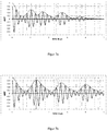
- Figur 6a
- Echofolgen einer Schrägmessung unter einem Winkel zum Lot der Probenoberfläche und
- Figur 6b
- Echofolgen einer Senkrechtmessung an einer Stahlplatte,
- Figur 7a
- eine Autokorrelationsfunktion der Echofolgen aus
Figur 6a und - Figur 7b
- eine Autokorrelationsfunktion der Echofolgen aus
Figur 6b .
- FIG. 1
- A first embodiment of the measuring arrangement for determining the speed of sound and wall thickness of a sample,
- FIG. 2
- A second embodiment of the measuring arrangement for determining the speed of sound and wall thickness of a sample,
- FIG. 3
- a third embodiment of the measuring arrangement for determining the speed of sound and wall thickness of a sample and
- FIG. 4
- A fourth embodiment of the measuring arrangement for determining the speed of sound and wall thickness of a sample,
- FIG. 5
- an embodiment of a measuring arrangement for determining the layer thickness of a multilayer system,
- FIG. 6a
- Echofolgen an oblique measurement at an angle to the solder of the sample surface and
- FIG. 6b
- Echofolgen of a vertical measurement on a steel plate,
- Figure 7a
- an autocorrelation function of the echo sequences
FIG. 6a and - FIG. 7b
- an autocorrelation function of the echo sequences
FIG. 6b ,
Die
Auf dem Koppelkörper 2 werden die Schallwandler angeordnet. Grundsätzlich können alle Schallwandler als Schallwandler-Arrays ausgeführt sein, d.h. sie können aus einem oder mehreren Piezoelementen bestehen, so dass die aktive Schallwandlerfläche durch zu- und abschalten der Piezoelemente geändert werden kann. Die Schallwandler sind unter verschiedenen Winkeln zur Probenoberfläche orientiert, so dass gesendete Ultraschallsignale mindestens zweimal die Probe 1 auf Schallwegen S 1 und S 2 durchlaufen und durch die Schallwandler wieder empfangen werden.On the
In
In
Das Verfahren zur Bestimmung der Schichtdicke w und der Schallgeschwindigkeit c einer Probe 1 basiert auf der Laufzeitmessung von zwei Ultraschallsignalen die unterschiedliche Schallwege S 1 und S 2 durch die Probe 1 gelaufen sind. Die Schallwege S 1 und S 2 sind dadurch charakterisiert, dass sie sich in ihrem Winkel zur Probenoberfläche und Länge unterscheiden, hingegen die Schallgeschwindigkeit der Ultraschallwellen auf beiden Schallwegen S 1 und S 2 gleich ist. Die Schallwege S 1 und S 2 in der Probe 1 können über verschiedene Messanordnungen realisiert werden. Die Realisierung der Laufzeitmessung von Signalen auf den Schallwegen S 1 und S 2 durch die Probe 1, sowie die einseitige Kopplung der Messanordnung an die Probe 1 ist den verschiedenen Messanordnungen gemeinsam.The method for determining the layer thickness w and the speed of sound c of a
Mit zwei Sende- und Empfangsschallwandler Paaren 3, 6 und 4, 5 welche unterschiedliche Einstrahlwinkel α 1 und α 2 zum Lot der Probenfläche aufweisen, können die Schallwege S 1 und S 2 mit einem Winkel β1 und β2 realisiert werden, siehe
Ein Ultraschallsignal welches vom Sendeschallwandler 3, 4 über den Koppelkörper 2 in die Probe 1 transmittiert wird, durchläuft den Schallweg S 1 bzw. S2, wenigstens einmal. Beim Austritt des Ultraschallsignals aus der Probe 1 wird das Ultraschallsignal in zwei Anteile aufgespalten: Ein Anteil wird in den Koppelkörper transmittiert und zum Empfangsschallwandler 5 bzw. 6 geleitet, ein anderer Anteil wird zurück in die Probe 1 reflektiert und durchläuft einen zusätzlichen Schallweg S 1* bzw. S 2 * (siehe
Im Folgenden werden alle Schallwege in der Probe 1, welche die gleiche Länge und den gleichen Winkel zur Probenoberfläche wie S 1 bzw. S 2 aufweisen, aber innerhalb der Probe aufgrund einer Reflexion an der Grenzschichte von Koppelkörper 2 und Probe 1 parallelverschoben zu dieser sind, auch als Schallweg S 1 bzw. S 2 bezeichnet.In the following, all sound paths in the
Durch die zuvor beschriebenen Mehrfachreflexionen innerhalb der Probe 1 bestehen die empfangenden Ultraschallsignale aus der Überlagerung mehrerer Signalanteile die eine unterschiedliche Anzahl der Schallwege S 1 bzw. S 2 in der Probe gelaufen sind. Die einzelnen Signalanteile weisen daher unterschiedliche Ankunftszeiten am Empfangsschallwandler auf. Die Überlagerung der beschriebenen Signalanteile wird als Echofolge bezeichnet: Der zeitlich erste Signalanteil ist keinmal den Schallweg S 1 bzw. S 2 gelaufen (wurde an der Probenoberfläche reflektiert und zum Empfänger geleitet), der zweite Signalanteil ist einmal den Schallweg S 1 bzw. S 2 gelaufen, spätere Signalanteile sind mehrfach Schallwege der Länge von S 1 bzw. S 2 gelaufen.As a result of the above-described multiple reflections within the
Mit jedem Durchlaufen der Probe 1 auf Schallwegen S 1 bzw. S 2 verzögert sich die Ankunftszeit des jeweiligen Signalanteils am Empfänger um die Laufzeit Δt 1 bzw. Δt 2. Am Empfänger 5 bzw. 6 ergibt sich somit ein Ultraschallsignal in Form einer Echofolge. Der zeitliche Abstand der eintreffenden Signalanteile ("Echofolgeabstand") innerhalb des Ultraschallsignals über den Schallweg S 1 bzw. S 2 beträgt Δt 1 bzw. Δt 2 Die Laufzeit Δt 1 bzw. Δt 2 ist durch die Schichtdicke w der Probe 1, die Schallgeschwindigkeit c in der Probe 1, die Schallgeschwindigkeit cα im Koppelkörper 2 und dem Einstrahlwinkel α 1 bzw. α 2 bestimmt. Die Schallwege S 1 bzw. S 2 selbst sind über die Schichtdicke w und über das Brechungsgesetzt über den Einstrahlwinkel α 1 bzw. α 2 bestimmt. Diese Winkel sind aus der Konstruktion der Messanordnung bekannt. Schlussendlich können zwei Gleichungen für die beiden Unbekannten Schichtdicke w und Schallgeschwindigkeit c in Abhängigkeit der Messgrößen Laufzeit Δt 1 und Δt 2 aufgestellt werden. 
Hierbei wird die abkürzende Schreibweise 
Im Folgenden wird anhand der beispielhaften Messanordnung aus
Damit die Schallgeschwindigkeit in der Probe 1 auf beiden Schallwegen S 1 und S 2 gleich ist, muss der Winkel der Schräganordnung möglichst unterhalb des ersten kritischen Winkels liegen. Wenn der Winkel der Schrägmessung über dem ersten kritischen Winkel aber unter dem zweiten kritischen Winkel liegt, muss zur Durchführung des Verfahrens ein Transversalwellen-Senkrechtschallwandler zur Senkrechtmessung verwendet werden. Dieser Fall ist für das in
Im Folgenden werden die Formeln für den Spezialfall der Ausführung mit einem senkrechten und einer schrägen Messanordnung offengelegt. 
Zur Bestimmung der Schallgeschwindigkeit c in der Probe 1 werden mittels der zuvor dargestellten Messanordnungen ("Schrägmessung" und "Senkrechtmessung") die Laufzeiten Δt 1 und Δt Senkrecht bestimmt. Mit den Gleichungen aus (1.3) kann anhand dieser beiden Messwerte die Schallgeschwindigkeit c und die Schichtdicke w in der Probe 1 bestimmt werden. Die Formel (1.3) ergibt sich als Spezialfall aus (1.1) mit α 2 = β 2 = 0 und Δt 2 = ΔtSenkrecht .To determine the speed of sound c in the sample 1 ( "skew measurement" and "vertical measurement"), the running times Δ t 1 and Δ t perpendicular determined by means of the previously shown measuring arrangements. With the equations of (1.3) the sound velocity c and the layer thickness w in the
Δt Senkrecht ist die Laufzeit auf dem Schallweg S 2 und entspricht dem Echofolgeabstand zwischen Ultraschallsignalen welche vom Sender 8 senkrecht zur Probenoberfläche n-mal und n+1-mal durch die Probe 1 und zurück zum Empfänger 8 gelaufen sind (mittels n Rückwandreflektionen in der Probe 1). Im Fall der Senkrechtmessung sind Sender und Empfänger der gleiche Schallwandler. Bei der Schrägmessung sind Sender 3 und Empfänger 6 unterschiedliche Schallwandler.Δ t perpendicular is the running time on the sound path S 2 and corresponds to the echo train spacing between ultrasonic signals which are n times, and n + 1 times run from the
Δt 1 ist die Laufzeit auf dem Schallweg S 1 und entspricht dem Echofolgeabstand zwischen Ultraschallsignalen welche vom Sender 3 unter dem Winkel β 1 zum Lot der Probenoberfläche n-mal und n+1-mal durch die Probe 1 und zurück zum Empfänger 6 gelaufen sind (mittels n Rückwandreflektion durch die Probe 1). Schallweg 10 und 11 stellen diesen Fall für n=1 dar.Δ t 1 is the transit time on the sound path S 1 and corresponds to the echo time interval between ultrasonic signals which have passed from the transmitter 3 n times through the angle β 1 to the sample surface and n + 1 times through the
Die Echofolgeabstände werden mit Hilfe der Autokorrelationsfunktion aus den aufgenommenen Echofolgen bestimmt.
Die Echofolge der Schrägmessung im Beispiel aus
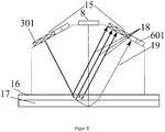
Zur Bestimmung der einzelnen Schichtdicken w in Mehrschichtsystemen wird jede einzelne Schicht 16 und 17 der Probe 1 mit dem zuvor beschriebenen Verfahren vermessen. Um die Laufzeiten aus den einzelnen Schichten 16 und 17 auswerten zu können, wird die Überlagerung der Echofolgen durch An- und Abschalten einzelner Piezoelemente 301, 601 vermieden. In
Die Echofolge aus der Senkrechtmessung mit dem Schallwandler 8 in
Dementsprechend kann mit der Formel (1.3) die Schichtdicke w und die Schallgeschwindigkeit c der oberen Schicht 16 der Probe 1 bestimmt werden.Accordingly, with the formula (1.3), the film thickness w and the sound velocity c of the
Um die untere Schicht 17 der Probe 1 zu vermessen werden am Empfänger des Schallwandlerpaares 15 die weiter rechts liegenden Elemente aktiviert (ohne Kreuze dargestellt) und die zuvor aktivierten Elemente (gekreuzt dargestellt) ausgeschaltet. Nun wird eine Echofolge bestehend aus Mehrfachreflexionen in der unteren Schicht 17 aufgenommen (Echofolge besteht aus Signalanteilen die mindestens einmal die Schicht 17 schräg durchlaufen haben) und der zeitliche Pulsfolgeabstand aufgrund von Mehrfachreflexion in Schicht 17 ausgewertet. Dies gelingt nur, wenn entweder weitere Echos aus der oberen Schicht 16 durch die Änderung der Empfangswandlerfläche größtenteils ausgeblendet werden können oder Mehrfachreflexionen in der oberen Schicht 16 stärker als in der unteren Schicht 17 gedämpft werden. Weiterhin kann die zuvor gewonnene Kenntnis der Schichtdicke der oberen Schicht 16 genutzt werden um die zeitliche Lage der Echos aus der oberen Schicht 16 vorherzusagen und somit aus der Auswertung der zeitlichen Pulsfolgeabstände für die untere Schicht 17 zu entfernen.In order to measure the
Die Echofolge aus Senkrechtmessung 8 in
- 11
- Probesample
- 22
- Koppelkörpercoupling body
- 201201
- Koppelflächecoupling surface
- 202202
- Deckfläche des Koppelkörpers 2Top surface of the coupling body. 2
- 203, 204, 205, 206203, 204, 205, 206
- longitudinale Seitenkantenlongitudinal side edges
- 33
- Schallwandlertransducer
- 301301
- Piezoelementepiezo elements
- 44
- Schallwandlertransducer
- 55
- Schallwandlertransducer
- 66
- Schallwandlertransducer
- 601601
- Piezoelementepiezo elements
- 77
- Reflektorenreflectors
- 88th
- Schallwandlertransducer
- 801801
- Piezoelementepiezo elements
- 99
- Schallwegsound path
- 1010
- Schallwegsound path
- 1111
- Schallwegsound path
- 1212
- Schallwegsound path
- 1313
- Schallwandler (Clamp-On-Durchflusssensoren)Sound transducers (clamp-on flow sensors)
- 131131
- Piezoelementepiezo elements
- 1414
- Schallwandler (Ultraschallwanddickenmesser)Sound transducer (ultrasonic wall thickness gauge)
- 141141
- Piezoelementepiezo elements
- 1515
- Schallwandlertransducer
- 1616
-
obere Schicht der Probe 1upper layer of the
sample 1 - 1717
-
untere Schicht der Probe 1lower layer of the
sample 1 - 1818
- Schallwegsound path
- 1919
- Schallwegsound path
- α1, α2 α 1 , α 2
-
Winkel des Schallstrahls zum Lot im Koppelkörper 2Angle of the sound beam to the solder in the
coupling body 2 - ββ 11 , β, β 22
-
Winkel des Schallstrahls zum Lot im in der Probe 1Angle of the sound beam to the solder in the
sample 1 - S 1, S 2 S 1 , S 2
- Schallwege in einer Schicht der ProbeSound paths in a layer of the sample
- S 1*, S 2 * S 1 *, S 2 *
- Schallwege in einer Schicht der Probe, parallelverschoben zu S 1 , S 2 Sound paths in a layer of the sample, parallel to S 1 , S 2
- Δt 1, Δt 2 Δ t 1, Δ t 2
- Laufzeiten des Ultraschalls auf Schallweg S 1, S 2 Running times of the ultrasound on sound path S 1 , S 2
- Δt Senkrecht Δ t vertical
- Laufzeit auf Schallweg S 1 bei der SenkrechtmessungRunning time on sound path S 1 for the vertical measurement
- cc
-
Schallgeschwindigkeit in der Probe 1Speed of sound in the
sample 1 - cα c α
-
Schallgeschwindigkeit im Koppelkörper 2Speed of sound in the
coupling body 2 - ww
- Schichtdickelayer thickness
-
K α
1 , K α2 K α1 , K α2 - Sensorkonstanten der Messanordnung mit Winkel α1 bzw. α2 im Koppelkörper 2Sensor constants of the measuring arrangement with angle α 1 or α 2 in the coupling body. 2
Claims (14)
die Schallwege (S 1, S2 ) erzeugt werden, indem auf der Oberfläche der ein- oder mehrlagigen Probe (1) mindestens ein Koppelkörper (2) angeordnet ist mit wenigstens zwei Schallwandlern (3, 4, 5, 6, 8, 13, 14, 15), welche die Ultraschallsignale auf den zwei verschiedenen Schallwegen (9, 10, 11, 12, 18, 19) durch den Koppelkörper (2) in die Probe (1) aussenden und wieder empfangen, wobei eine Berechnung der Schichtdicke (w) und Schallgeschwindigkeit (c) in der Schicht mittels von Gleichungen


the sound paths ( S 1 , S 2 ) are produced by arranging at least one coupling body (2) on the surface of the single-layer or multi-layer sample (1) with at least two sound transducers (3, 4, 5, 6, 8, 13, 14, 15), which transmit and receive the ultrasonic signals on the two different sound paths (9, 10, 11, 12, 18, 19) through the coupling body (2) into the sample (1), wherein a calculation of the layer thickness (w ) and speed of sound ( c ) in the layer by means of equations
die Laufzeit (Δt 1) als Position eines ersten Nebenmaximums einer Autokorrelationsfunktion einer Echofolge bestimmt wird, wobei die Echofolge aus Ultraschallsignalen besteht, welche vom Schallwandler (3) unter dem Winkel (β 1) zum Lot der Probenoberfläche wenigstens n-mal und n+1-mal durch die zu vermessende Schicht der Probe (1) und zurück zum Schallwandler (3) oder Schallwandler (5) mittels n Rückwandreflektion durch die Probe (1) gelaufen sind.A method according to claim 2, characterized in that
the transit time (Δ t 1 ) is determined as the position of a first secondary maximum of an autocorrelation function of an echo sequence, the echo train consisting of ultrasound signals emitted by the transducer (3) at an angle ( β 1 ) to the sample surface at least n times and n + 1 through the layer to be measured of the sample (1) and back to the transducer (3) or transducer (5) by n back wall reflection through the sample (1) have run.
die Laufzeit (Δt 2) als Position eines ersten Nebenmaximums einer Autokorrelationsfunktion einer Echofolge bestimmt wird, wobei die Echofolge aus Ultraschallsignalen besteht, welche vom Schallwandler (8) oder Schallwandler (4) unter dem Winkel (β 2) zum Lot der Probenoberfläche wenigstens n-mal und n+1-mal durch die zu vermessende Schicht der Probe (1) und zurück zum Schallwandler (8), Schallwandler (4) oder Schallwandler (5) mittels n Rückwandreflektion durch die Probe (1) gelaufen sind.A method according to claim 2, characterized in that
the duration (Δ t 2) as a position of a first secondary maximum of an autocorrelation function of an echo sequence is determined, wherein the echo sequence consists of ultrasonic signals by the transducer (8) or transducer (4) at the angle (β 2) to the perpendicular of the sample surface at least n Run through the sample (1) and back to the sound transducer (8), sound transducer (4) or transducer (5) through the sample (1) through the sample to be measured 1 time and n + 1 times by means of back reflection.
durch Zu- und Abschalten einzelner Piezoelemente (301, 601, 801; 131, 141) einer aktiven Schallwandlerfläche der Schallwandler (3, 4, 5, 6, 8, 13, 14, 15), welche mehrere Piezoelemente (301, 601, 801; 131, 141) enthalten, Signalanteile, welche die Probe (1) auf den Schallwegen (S 1, S 2) durchlaufen und am Schallwandler (3, 4, 5, 6, 8, 13, 14, 15) auftreffen, ausgewählt werden.A method according to claim 2, characterized in that
By switching on and off of individual piezo elements (301, 601, 801, 131, 141) of an active sound transducer surface of the sound transducers (3, 4, 5, 6, 8, 13, 14, 15), which a plurality of piezo elements (301, 601, 801 131, 141), signal components which pass through the sample (1) on the sound paths ( S 1 , S 2 ) and impinge on the sound transducer (3, 4, 5, 6, 8, 13, 14, 15) are selected ,
für eine wenigstens zweilagige Probe (1) durch Zu- und Abschalten einzelner Piezoelemente (301, 601, 801; 131, 141) einer aktiven Schallwandlerfläche der Schallwandler (3, 4, 5, 6, 8, 13, 14, 15), für jede einzelne Schicht die Schichtdicke (w) und die Schallgeschwindigkeit (c) bestimmt werden.A method according to claim 5, characterized in that
for an at least two-layered sample (1) by switching on and off individual Piezo elements (301, 601, 801, 131, 141) of an active sound transducer surface of the sound transducers (3, 4, 5, 6, 8, 13, 14, 15), for each individual layer the layer thickness (w) and the speed of sound ( c ) be determined.
wobei auf einer Oberfläche der ein- oder mehrlagigen Probe (1) wenigstens ein Koppelkörper (2) angeordnet ist, mit wenigstens zwei Schallwandlern (3, 4, 5, 6, 8, 13, 14, 15), welche unter definierten Winkeln auf dem Koppelkörper (2) angeordnet sind, so dass der Ultraschall unter einem Einstrahlwinkel (α1, α2 ) durch den Koppelkörper (2) in die Probe (1) gelangt und wenigstens zwei Schallwege (S 1, S 2) in einer Schicht der Probe (1) durchläuft und von dort zurück zu den wenigstens zwei Schallwandlern (3, 4, 5, 6, 8, 13, 14, 15) unter einem Winkel (β 1, β 2) reflektiert wird.Measuring arrangement for measuring layer thickness ( w ) and speed of sound ( c ) by means of ultrasound of a single- or multilayer sample (1) according to a method with claims 1 to 6,
wherein on a surface of the single or multilayer sample (1) at least one coupling body (2) is arranged, with at least two sound transducers (3, 4, 5, 6, 8, 13, 14, 15), which at defined angles on the Coupling body (2) are arranged so that the ultrasound at an angle of incidence ( α 1 , α 2 ) passes through the coupling body (2) in the sample (1) and at least two sound paths ( S 1 , S 2 ) in a layer of the sample (1) and from there back to the at least two sound transducers (3, 4, 5, 6, 8, 13, 14, 15) at an angle ( β 1 , β 2 ) is reflected.
der Koppelkörper (2) in seiner Grundform ein Quader ist und seine obere Deckfläche (202) abgeschrägte longitudinale Seitenkanten (203, 204, 205, 206) aufweist.Measuring arrangement according to claim 7, characterized in that
the coupling body (2) is a cuboid in its basic form and its upper cover surface (202) has beveled longitudinal side edges (203, 204, 205, 206).
zwei Sender-Empfänger-Paare aus jeweils zwei Schallwandlern (3, 4, 5, 6, 13, 15) mit einem Winkel (α1, α2 ) auf dem Koppelkörper (2) so angeordnet sind, dass ein erstes Sender-Empfänger-Paar einen Winkel (β 1) zur Probenoberfläche aufweist, welcher zu dem Winkel (β 2) des zweiten Sender-Empfänger-Paars verschieden ist.Measuring arrangement according to claim 7, characterized in that
two transmitter-receiver pairs of two sound transducers (3, 4, 5, 6, 13, 15) are arranged at an angle ( α 1 , α 2 ) on the coupling body (2) such that a first transceiver Pair has an angle ( β 1 ) to the sample surface which is different from the angle ( β 2 ) of the second transmitter-receiver pair.
die Schallwandler (3, 6, 8, 13, 14) aus Schallwandler-Arrays mit einem oder mehreren Piezoelementen (301, 601, 801, 131, 141) bestehen.Measuring arrangement according to one of the preceding claims, characterized in that
the sound transducers (3, 6, 8, 13, 14) consist of transducer arrays with one or more piezo elements (301, 601, 801, 131, 141).
eine aktive Schallwandlerfläche der Schallwandler (3, 6, 8, 14) mit mehreren Piezoelementen (301, 601, 801, 131, 141) durch Zu- und Abschalten einzelner Piezoelemente (301, 601, 801, 131, 141) bestimmt ist.Measuring arrangement according to claim 13, characterized in that
an active sound transducer surface of the sound transducer (3, 6, 8, 14) with a plurality of piezo elements (301, 601, 801, 131, 141) by switching on and off of individual piezo elements (301, 601, 801, 131, 141) is determined.
Priority Applications (5)
| Application Number | Priority Date | Filing Date | Title |
|---|---|---|---|
| EP17195986.9A EP3470775B1 (en) | 2017-10-11 | 2017-10-11 | Method and measuring assembly for measuring layer thickness and sound wave speed in single-layered or multilayered samples by means of ultrasound without a priori knowledge of the other variable |
| CN201880064992.0A CN111183332B (en) | 2017-10-11 | 2018-10-04 | Method and device for measuring the layer thickness and the sound velocity of a layer of a single-layer or multi-layer sample |
| PCT/EP2018/077002 WO2019072678A1 (en) | 2017-10-11 | 2018-10-04 | Method and measuring arrangement for measuring layer thickness and sound velocity in single- or multilayered samples using ultrasound, without a priori knowledge of the other variable |
| JP2020519985A JP7133012B2 (en) | 2017-10-11 | 2018-10-04 | Method and apparatus for measuring layer thickness and sound velocity in single- or multi-layer samples using ultrasound without prior knowledge of each other |
| US16/845,816 US11353348B2 (en) | 2017-10-11 | 2020-04-10 | Method and measuring assembly for measuring layer thickness and sound velocity in single- or multilayered samples using ultrasound, without a priori knowledge of the other variable |
Applications Claiming Priority (1)
| Application Number | Priority Date | Filing Date | Title |
|---|---|---|---|
| EP17195986.9A EP3470775B1 (en) | 2017-10-11 | 2017-10-11 | Method and measuring assembly for measuring layer thickness and sound wave speed in single-layered or multilayered samples by means of ultrasound without a priori knowledge of the other variable |
Publications (2)
| Publication Number | Publication Date |
|---|---|
| EP3470775A1 true EP3470775A1 (en) | 2019-04-17 |
| EP3470775B1 EP3470775B1 (en) | 2022-12-14 |
Family
ID=60083146
Family Applications (1)
| Application Number | Title | Priority Date | Filing Date |
|---|---|---|---|
| EP17195986.9A Active EP3470775B1 (en) | 2017-10-11 | 2017-10-11 | Method and measuring assembly for measuring layer thickness and sound wave speed in single-layered or multilayered samples by means of ultrasound without a priori knowledge of the other variable |
Country Status (5)
| Country | Link |
|---|---|
| US (1) | US11353348B2 (en) |
| EP (1) | EP3470775B1 (en) |
| JP (1) | JP7133012B2 (en) |
| CN (1) | CN111183332B (en) |
| WO (1) | WO2019072678A1 (en) |
Cited By (3)
| Publication number | Priority date | Publication date | Assignee | Title |
|---|---|---|---|---|
| CN112304262A (en) * | 2020-10-21 | 2021-02-02 | 上海建工集团股份有限公司 | Concrete pumping pipeline wall thickness detection method |
| US20220260366A1 (en) * | 2021-02-12 | 2022-08-18 | Holloway Ndt & Engineering Inc. | Ultrasonic testing using a phased array |
| WO2022198248A1 (en) * | 2021-03-24 | 2022-09-29 | Ac2T Research Gmbh | Device for determining chemico-physical properties in a tribological system |
Families Citing this family (4)
| Publication number | Priority date | Publication date | Assignee | Title |
|---|---|---|---|---|
| US11726064B2 (en) | 2020-07-22 | 2023-08-15 | Mueller International Llc | Acoustic pipe condition assessment using coherent averaging |
| US11609348B2 (en) * | 2020-12-29 | 2023-03-21 | Mueller International, Llc | High-resolution acoustic pipe condition assessment using in-bracket pipe excitation |
| CN114184146A (en) * | 2021-12-03 | 2022-03-15 | 上海船舶工程质量检测有限公司 | System and method for measuring longitudinal wave sound velocity distribution of high-sound attenuation/large-thickness material |
| CN116499539B (en) * | 2023-03-15 | 2024-01-19 | 杭州山科智能科技股份有限公司 | Ultrasonic water meter and measuring method |
Citations (10)
| Publication number | Priority date | Publication date | Assignee | Title |
|---|---|---|---|---|
| US4398421A (en) | 1981-12-23 | 1983-08-16 | Hartford Steam Boiler Inspection And Insurance Company | Ultrasonic thickness measuring apparatus and method |
| DE3441894A1 (en) * | 1984-11-16 | 1986-07-24 | Krautkrämer GmbH, 5000 Köln | Method and device for determining the wall thickness and/or the speed of sound of test specimens with ultrasonic pulses |
| US5349860A (en) | 1989-11-28 | 1994-09-27 | Nkk Corporation | Apparatus for measuring the thickness of clad material |
| US6035717A (en) | 1998-05-12 | 2000-03-14 | Krautkramer Branson, Inc. | Method and apparatus for measuring the thickness of a coated material |
| US6070466A (en) | 1997-05-14 | 2000-06-06 | Scanmaster Systems (Irt) Ltd. | Device for ultrasonic inspection of a multi-layer metal workpiece |
| US20040250624A1 (en) * | 2003-06-16 | 2004-12-16 | Agostino Abbate | Method and apparatus for measuring part thickness having an external coating using impedance matching delay lines |
| US6883376B2 (en) | 2001-01-23 | 2005-04-26 | Wright State University | Method for determining the wall thickness and the speed of sound in a tube from reflected and transmitted ultrasound pulses |
| US20060191342A1 (en) | 2002-07-17 | 2006-08-31 | Peter Renzel | Method for determining the sound velocity in a basic material, particularly for measuring the thickness of a wall |
| DE102010037981A1 (en) * | 2010-10-05 | 2012-04-05 | Deutsches Zentrum für Luft- und Raumfahrt e.V. | Ultrasound measuring method for e.g. monitoring hardening of laminate of fiber composite part during manufacturing part, involves coupling ultrasound signal in object through advancing body below angle to surface normal of coupling surface |
| US20140020478A1 (en) * | 2012-07-18 | 2014-01-23 | General Electric Company | Ultrasonic wedge and method for determining the speed of sound in same |
Family Cites Families (11)
| Publication number | Priority date | Publication date | Assignee | Title |
|---|---|---|---|---|
| US439421A (en) * | 1890-10-28 | Navigable air-ship | ||
| US4413517A (en) * | 1979-07-30 | 1983-11-08 | Sonic Instruments, Inc. | Apparatus and method for determining thickness |
| JPH11108648A (en) * | 1997-09-30 | 1999-04-23 | Nobuhiko Nishiwaki | Measuring method of thickness and distance by using ultrasonic wave |
| AU7928898A (en) * | 1998-03-03 | 1999-09-20 | Sunlight Medical, Ltd | Determination of acoustic velocity in bone |
| JP4363699B2 (en) * | 1999-05-07 | 2009-11-11 | 株式会社ニチゾウテック | Method for detecting carburized layer and measuring thickness thereof |
| JP4865781B2 (en) * | 2008-11-14 | 2012-02-01 | 三菱重工業株式会社 | Ultrasonic measurement method and apparatus |
| JP5884993B2 (en) * | 2013-09-12 | 2016-03-15 | 横河電機株式会社 | Ultrasonic piping measuring device |
| JP6291814B2 (en) * | 2013-11-29 | 2018-03-14 | セイコーエプソン株式会社 | Ultrasonic transducer device, ultrasonic measuring device and ultrasonic imaging device |
| CN104483385B (en) * | 2014-12-05 | 2017-02-22 | 中国航空工业集团公司北京航空材料研究院 | Method for measuring longitudinal wave velocity of anisotropic material |
| JP2016161400A (en) * | 2015-03-02 | 2016-09-05 | 株式会社ジェイテクト | Roller attitude measurement device and roller attitude measurement method |
| CN105651215B (en) * | 2016-03-19 | 2017-10-13 | 大连理工大学 | A kind of coating thickness measurement method under velocity of ultrasonic sound unknown condition |
-
2017
- 2017-10-11 EP EP17195986.9A patent/EP3470775B1/en active Active
-
2018
- 2018-10-04 CN CN201880064992.0A patent/CN111183332B/en active Active
- 2018-10-04 JP JP2020519985A patent/JP7133012B2/en active Active
- 2018-10-04 WO PCT/EP2018/077002 patent/WO2019072678A1/en active Application Filing
-
2020
- 2020-04-10 US US16/845,816 patent/US11353348B2/en active Active
Patent Citations (10)
| Publication number | Priority date | Publication date | Assignee | Title |
|---|---|---|---|---|
| US4398421A (en) | 1981-12-23 | 1983-08-16 | Hartford Steam Boiler Inspection And Insurance Company | Ultrasonic thickness measuring apparatus and method |
| DE3441894A1 (en) * | 1984-11-16 | 1986-07-24 | Krautkrämer GmbH, 5000 Köln | Method and device for determining the wall thickness and/or the speed of sound of test specimens with ultrasonic pulses |
| US5349860A (en) | 1989-11-28 | 1994-09-27 | Nkk Corporation | Apparatus for measuring the thickness of clad material |
| US6070466A (en) | 1997-05-14 | 2000-06-06 | Scanmaster Systems (Irt) Ltd. | Device for ultrasonic inspection of a multi-layer metal workpiece |
| US6035717A (en) | 1998-05-12 | 2000-03-14 | Krautkramer Branson, Inc. | Method and apparatus for measuring the thickness of a coated material |
| US6883376B2 (en) | 2001-01-23 | 2005-04-26 | Wright State University | Method for determining the wall thickness and the speed of sound in a tube from reflected and transmitted ultrasound pulses |
| US20060191342A1 (en) | 2002-07-17 | 2006-08-31 | Peter Renzel | Method for determining the sound velocity in a basic material, particularly for measuring the thickness of a wall |
| US20040250624A1 (en) * | 2003-06-16 | 2004-12-16 | Agostino Abbate | Method and apparatus for measuring part thickness having an external coating using impedance matching delay lines |
| DE102010037981A1 (en) * | 2010-10-05 | 2012-04-05 | Deutsches Zentrum für Luft- und Raumfahrt e.V. | Ultrasound measuring method for e.g. monitoring hardening of laminate of fiber composite part during manufacturing part, involves coupling ultrasound signal in object through advancing body below angle to surface normal of coupling surface |
| US20140020478A1 (en) * | 2012-07-18 | 2014-01-23 | General Electric Company | Ultrasonic wedge and method for determining the speed of sound in same |
Cited By (5)
| Publication number | Priority date | Publication date | Assignee | Title |
|---|---|---|---|---|
| CN112304262A (en) * | 2020-10-21 | 2021-02-02 | 上海建工集团股份有限公司 | Concrete pumping pipeline wall thickness detection method |
| CN112304262B (en) * | 2020-10-21 | 2022-03-15 | 上海建工集团股份有限公司 | Concrete pumping pipeline wall thickness detection method |
| US20220260366A1 (en) * | 2021-02-12 | 2022-08-18 | Holloway Ndt & Engineering Inc. | Ultrasonic testing using a phased array |
| US11578971B2 (en) * | 2021-02-12 | 2023-02-14 | Holloway Ndt & Engineering Inc. | Ultrasonic testing using a phased array |
| WO2022198248A1 (en) * | 2021-03-24 | 2022-09-29 | Ac2T Research Gmbh | Device for determining chemico-physical properties in a tribological system |
Also Published As
| Publication number | Publication date |
|---|---|
| CN111183332A (en) | 2020-05-19 |
| CN111183332B (en) | 2022-02-25 |
| US11353348B2 (en) | 2022-06-07 |
| JP7133012B2 (en) | 2022-09-07 |
| WO2019072678A1 (en) | 2019-04-18 |
| EP3470775B1 (en) | 2022-12-14 |
| JP2020537129A (en) | 2020-12-17 |
| US20200240821A1 (en) | 2020-07-30 |
Similar Documents
| Publication | Publication Date | Title |
|---|---|---|
| EP3470775B1 (en) | Method and measuring assembly for measuring layer thickness and sound wave speed in single-layered or multilayered samples by means of ultrasound without a priori knowledge of the other variable | |
| DE19606083B4 (en) | Delay line for an ultrasonic probe and method of using the same | |
| EP1525430B1 (en) | Method for determining the sound velocity in a basic material, particularly for measuring the thickness of a wall | |
| EP2335064B1 (en) | Pulse-echo method by means of an array-type probe and temperature compensation | |
| EP2440888B1 (en) | Method for measuring a measurement variable | |
| EP2335063B1 (en) | Pulse-echo method with determination of the delay-line geometry | |
| DE112015002257T5 (en) | Apparatus and method for measuring the pressure within a pipe or container | |
| DE10254053B4 (en) | Method and device for determining and / or monitoring a volume and / or mass flow | |
| WO2012120039A2 (en) | Method for ultrasonic clamp-on flow measurement and device for implementing the method | |
| EP1762841A1 (en) | Method and device for ultrasonic testing of a workpiece having an uneven surface | |
| DE102018208824B4 (en) | Method for the non-destructive examination of a test body using ultrasound | |
| DE102004027798A1 (en) | Method and apparatus for measuring the thickness of parts having an outer coating using impedance matching delay lines | |
| DE19535848C1 (en) | Fluid acoustic impedance measuring device | |
| DE10214678B4 (en) | Process for the non-destructive determination of deposits and incrustations in liquid-filled containers or pipelines | |
| EP3517946B1 (en) | Method for determining a corrected value for viscosity-dependent sound velocity in a fluid to be examined | |
| EP2981785B1 (en) | Method for determining the layer thickness of a connecting layer between two packaging layers | |
| DE102010037981B4 (en) | Ultrasonic measuring method and apparatus, in particular for curing monitoring and laminate thickness determination in fiber composite part production | |
| WO2020038809A1 (en) | Method for operating a fluid sensor device and fluid sensor device | |
| WO2019201804A1 (en) | Device and method for determining the expansion of imperfections by means of v-transmission | |
| DE3732834C2 (en) | ||
| DE102011102641A1 (en) | Apparatus and method for the quantitative detection of a physical property of a liquid or gaseous sample medium | |
| DE19534503A1 (en) | Single-layer thickness measuring at multilayer plastic pipe or plate or layers e.g. PE-Al-PE heating tubes | |
| DE3545889C1 (en) | Method for determining the elastic material constants of the material of a component part, and appliance for implementing the method | |
| DE102018119206A1 (en) | Method for detecting the geometry of an area of an object using ultrasound | |
| DE3142076A1 (en) | Method and device for continuously measuring distances and position displacements |
Legal Events
| Date | Code | Title | Description |
|---|---|---|---|
| PUAI | Public reference made under article 153(3) epc to a published international application that has entered the european phase |
Free format text: ORIGINAL CODE: 0009012 |
|
| STAA | Information on the status of an ep patent application or granted ep patent |
Free format text: STATUS: THE APPLICATION HAS BEEN PUBLISHED |
|
| AK | Designated contracting states |
Kind code of ref document: A1 Designated state(s): AL AT BE BG CH CY CZ DE DK EE ES FI FR GB GR HR HU IE IS IT LI LT LU LV MC MK MT NL NO PL PT RO RS SE SI SK SM TR |
|
| AX | Request for extension of the european patent |
Extension state: BA ME |
|
| STAA | Information on the status of an ep patent application or granted ep patent |
Free format text: STATUS: REQUEST FOR EXAMINATION WAS MADE |
|
| 17P | Request for examination filed |
Effective date: 20190919 |
|
| RBV | Designated contracting states (corrected) |
Designated state(s): AL AT BE BG CH CY CZ DE DK EE ES FI FR GB GR HR HU IE IS IT LI LT LU LV MC MK MT NL NO PL PT RO RS SE SI SK SM TR |
|
| STAA | Information on the status of an ep patent application or granted ep patent |
Free format text: STATUS: EXAMINATION IS IN PROGRESS |
|
| 17Q | First examination report despatched |
Effective date: 20210608 |
|
| STAA | Information on the status of an ep patent application or granted ep patent |
Free format text: STATUS: EXAMINATION IS IN PROGRESS |
|
| GRAP | Despatch of communication of intention to grant a patent |
Free format text: ORIGINAL CODE: EPIDOSNIGR1 |
|
| STAA | Information on the status of an ep patent application or granted ep patent |
Free format text: STATUS: GRANT OF PATENT IS INTENDED |
|
| INTG | Intention to grant announced |
Effective date: 20220712 |
|
| GRAS | Grant fee paid |
Free format text: ORIGINAL CODE: EPIDOSNIGR3 |
|
| GRAA | (expected) grant |
Free format text: ORIGINAL CODE: 0009210 |
|
| STAA | Information on the status of an ep patent application or granted ep patent |
Free format text: STATUS: THE PATENT HAS BEEN GRANTED |
|
| AK | Designated contracting states |
Kind code of ref document: B1 Designated state(s): AL AT BE BG CH CY CZ DE DK EE ES FI FR GB GR HR HU IE IS IT LI LT LU LV MC MK MT NL NO PL PT RO RS SE SI SK SM TR |
|
| REG | Reference to a national code |
Ref country code: GB Ref legal event code: FG4D Free format text: NOT ENGLISH |
|
| REG | Reference to a national code |
Ref country code: CH Ref legal event code: EP |
|
| REG | Reference to a national code |
Ref country code: DE Ref legal event code: R096 Ref document number: 502017014209 Country of ref document: DE |
|
| REG | Reference to a national code |
Ref country code: IE Ref legal event code: FG4D Free format text: LANGUAGE OF EP DOCUMENT: GERMAN |
|
| REG | Reference to a national code |
Ref country code: AT Ref legal event code: REF Ref document number: 1537931 Country of ref document: AT Kind code of ref document: T Effective date: 20230115 |
|
| REG | Reference to a national code |
Ref country code: LT Ref legal event code: MG9D |
|
| REG | Reference to a national code |
Ref country code: NL Ref legal event code: MP Effective date: 20221214 |
|
| PG25 | Lapsed in a contracting state [announced via postgrant information from national office to epo] |
Ref country code: SE Free format text: LAPSE BECAUSE OF FAILURE TO SUBMIT A TRANSLATION OF THE DESCRIPTION OR TO PAY THE FEE WITHIN THE PRESCRIBED TIME-LIMIT Effective date: 20221214 Ref country code: NO Free format text: LAPSE BECAUSE OF FAILURE TO SUBMIT A TRANSLATION OF THE DESCRIPTION OR TO PAY THE FEE WITHIN THE PRESCRIBED TIME-LIMIT Effective date: 20230314 Ref country code: LT Free format text: LAPSE BECAUSE OF FAILURE TO SUBMIT A TRANSLATION OF THE DESCRIPTION OR TO PAY THE FEE WITHIN THE PRESCRIBED TIME-LIMIT Effective date: 20221214 Ref country code: FI Free format text: LAPSE BECAUSE OF FAILURE TO SUBMIT A TRANSLATION OF THE DESCRIPTION OR TO PAY THE FEE WITHIN THE PRESCRIBED TIME-LIMIT Effective date: 20221214 |
|
| PG25 | Lapsed in a contracting state [announced via postgrant information from national office to epo] |
Ref country code: RS Free format text: LAPSE BECAUSE OF FAILURE TO SUBMIT A TRANSLATION OF THE DESCRIPTION OR TO PAY THE FEE WITHIN THE PRESCRIBED TIME-LIMIT Effective date: 20221214 Ref country code: LV Free format text: LAPSE BECAUSE OF FAILURE TO SUBMIT A TRANSLATION OF THE DESCRIPTION OR TO PAY THE FEE WITHIN THE PRESCRIBED TIME-LIMIT Effective date: 20221214 Ref country code: HR Free format text: LAPSE BECAUSE OF FAILURE TO SUBMIT A TRANSLATION OF THE DESCRIPTION OR TO PAY THE FEE WITHIN THE PRESCRIBED TIME-LIMIT Effective date: 20221214 Ref country code: GR Free format text: LAPSE BECAUSE OF FAILURE TO SUBMIT A TRANSLATION OF THE DESCRIPTION OR TO PAY THE FEE WITHIN THE PRESCRIBED TIME-LIMIT Effective date: 20230315 |
|
| PG25 | Lapsed in a contracting state [announced via postgrant information from national office to epo] |
Ref country code: NL Free format text: LAPSE BECAUSE OF FAILURE TO SUBMIT A TRANSLATION OF THE DESCRIPTION OR TO PAY THE FEE WITHIN THE PRESCRIBED TIME-LIMIT Effective date: 20221214 |
|
| PG25 | Lapsed in a contracting state [announced via postgrant information from national office to epo] |
Ref country code: SM Free format text: LAPSE BECAUSE OF FAILURE TO SUBMIT A TRANSLATION OF THE DESCRIPTION OR TO PAY THE FEE WITHIN THE PRESCRIBED TIME-LIMIT Effective date: 20221214 Ref country code: RO Free format text: LAPSE BECAUSE OF FAILURE TO SUBMIT A TRANSLATION OF THE DESCRIPTION OR TO PAY THE FEE WITHIN THE PRESCRIBED TIME-LIMIT Effective date: 20221214 Ref country code: PT Free format text: LAPSE BECAUSE OF FAILURE TO SUBMIT A TRANSLATION OF THE DESCRIPTION OR TO PAY THE FEE WITHIN THE PRESCRIBED TIME-LIMIT Effective date: 20230414 Ref country code: ES Free format text: LAPSE BECAUSE OF FAILURE TO SUBMIT A TRANSLATION OF THE DESCRIPTION OR TO PAY THE FEE WITHIN THE PRESCRIBED TIME-LIMIT Effective date: 20221214 Ref country code: EE Free format text: LAPSE BECAUSE OF FAILURE TO SUBMIT A TRANSLATION OF THE DESCRIPTION OR TO PAY THE FEE WITHIN THE PRESCRIBED TIME-LIMIT Effective date: 20221214 Ref country code: CZ Free format text: LAPSE BECAUSE OF FAILURE TO SUBMIT A TRANSLATION OF THE DESCRIPTION OR TO PAY THE FEE WITHIN THE PRESCRIBED TIME-LIMIT Effective date: 20221214 |
|
| PG25 | Lapsed in a contracting state [announced via postgrant information from national office to epo] |
Ref country code: SK Free format text: LAPSE BECAUSE OF FAILURE TO SUBMIT A TRANSLATION OF THE DESCRIPTION OR TO PAY THE FEE WITHIN THE PRESCRIBED TIME-LIMIT Effective date: 20221214 Ref country code: PL Free format text: LAPSE BECAUSE OF FAILURE TO SUBMIT A TRANSLATION OF THE DESCRIPTION OR TO PAY THE FEE WITHIN THE PRESCRIBED TIME-LIMIT Effective date: 20221214 Ref country code: IS Free format text: LAPSE BECAUSE OF FAILURE TO SUBMIT A TRANSLATION OF THE DESCRIPTION OR TO PAY THE FEE WITHIN THE PRESCRIBED TIME-LIMIT Effective date: 20230414 Ref country code: AL Free format text: LAPSE BECAUSE OF FAILURE TO SUBMIT A TRANSLATION OF THE DESCRIPTION OR TO PAY THE FEE WITHIN THE PRESCRIBED TIME-LIMIT Effective date: 20221214 |
|
| REG | Reference to a national code |
Ref country code: DE Ref legal event code: R097 Ref document number: 502017014209 Country of ref document: DE |
|
| PLBE | No opposition filed within time limit |
Free format text: ORIGINAL CODE: 0009261 |
|
| STAA | Information on the status of an ep patent application or granted ep patent |
Free format text: STATUS: NO OPPOSITION FILED WITHIN TIME LIMIT |
|
| PG25 | Lapsed in a contracting state [announced via postgrant information from national office to epo] |
Ref country code: DK Free format text: LAPSE BECAUSE OF FAILURE TO SUBMIT A TRANSLATION OF THE DESCRIPTION OR TO PAY THE FEE WITHIN THE PRESCRIBED TIME-LIMIT Effective date: 20221214 |
|
| 26N | No opposition filed |
Effective date: 20230915 |
|
| PG25 | Lapsed in a contracting state [announced via postgrant information from national office to epo] |
Ref country code: SI Free format text: LAPSE BECAUSE OF FAILURE TO SUBMIT A TRANSLATION OF THE DESCRIPTION OR TO PAY THE FEE WITHIN THE PRESCRIBED TIME-LIMIT Effective date: 20221214 |
|
| PGFP | Annual fee paid to national office [announced via postgrant information from national office to epo] |
Ref country code: FR Payment date: 20230919 Year of fee payment: 7 |
|
| PGFP | Annual fee paid to national office [announced via postgrant information from national office to epo] |
Ref country code: GB Payment date: 20231017 Year of fee payment: 7 |
|
| PGFP | Annual fee paid to national office [announced via postgrant information from national office to epo] |
Ref country code: DE Payment date: 20231009 Year of fee payment: 7 Ref country code: CH Payment date: 20231101 Year of fee payment: 7 |