EP3470737B1 - Turbulenzerzeugende struktur zur verbesserung der linienkühlung einer gasturbinenbrennkammer - Google Patents
Turbulenzerzeugende struktur zur verbesserung der linienkühlung einer gasturbinenbrennkammer Download PDFInfo
- Publication number
- EP3470737B1 EP3470737B1 EP18190909.4A EP18190909A EP3470737B1 EP 3470737 B1 EP3470737 B1 EP 3470737B1 EP 18190909 A EP18190909 A EP 18190909A EP 3470737 B1 EP3470737 B1 EP 3470737B1
- Authority
- EP
- European Patent Office
- Prior art keywords
- liner
- turbulence
- cooling
- generating structure
- turbulence generator
- Prior art date
- Legal status (The legal status is an assumption and is not a legal conclusion. Google has not performed a legal analysis and makes no representation as to the accuracy of the status listed.)
- Active
Links
Images




Classifications
-
- F—MECHANICAL ENGINEERING; LIGHTING; HEATING; WEAPONS; BLASTING
- F23—COMBUSTION APPARATUS; COMBUSTION PROCESSES
- F23R—GENERATING COMBUSTION PRODUCTS OF HIGH PRESSURE OR HIGH VELOCITY, e.g. GAS-TURBINE COMBUSTION CHAMBERS
- F23R3/00—Continuous combustion chambers using liquid or gaseous fuel
- F23R3/002—Wall structures
-
- F—MECHANICAL ENGINEERING; LIGHTING; HEATING; WEAPONS; BLASTING
- F23—COMBUSTION APPARATUS; COMBUSTION PROCESSES
- F23R—GENERATING COMBUSTION PRODUCTS OF HIGH PRESSURE OR HIGH VELOCITY, e.g. GAS-TURBINE COMBUSTION CHAMBERS
- F23R3/00—Continuous combustion chambers using liquid or gaseous fuel
- F23R3/02—Continuous combustion chambers using liquid or gaseous fuel characterised by the air-flow or gas-flow configuration
-
- F—MECHANICAL ENGINEERING; LIGHTING; HEATING; WEAPONS; BLASTING
- F01—MACHINES OR ENGINES IN GENERAL; ENGINE PLANTS IN GENERAL; STEAM ENGINES
- F01D—NON-POSITIVE DISPLACEMENT MACHINES OR ENGINES, e.g. STEAM TURBINES
- F01D9/00—Stators
- F01D9/02—Nozzles; Nozzle boxes; Stator blades; Guide conduits, e.g. individual nozzles
- F01D9/023—Transition ducts between combustor cans and first stage of the turbine in gas-turbine engines; their cooling or sealings
-
- F—MECHANICAL ENGINEERING; LIGHTING; HEATING; WEAPONS; BLASTING
- F02—COMBUSTION ENGINES; HOT-GAS OR COMBUSTION-PRODUCT ENGINE PLANTS
- F02C—GAS-TURBINE PLANTS; AIR INTAKES FOR JET-PROPULSION PLANTS; CONTROLLING FUEL SUPPLY IN AIR-BREATHING JET-PROPULSION PLANTS
- F02C7/00—Features, components parts, details or accessories, not provided for in, or of interest apart form groups F02C1/00 - F02C6/00; Air intakes for jet-propulsion plants
- F02C7/12—Cooling of plants
- F02C7/16—Cooling of plants characterised by cooling medium
- F02C7/18—Cooling of plants characterised by cooling medium the medium being gaseous, e.g. air
-
- F—MECHANICAL ENGINEERING; LIGHTING; HEATING; WEAPONS; BLASTING
- F23—COMBUSTION APPARATUS; COMBUSTION PROCESSES
- F23R—GENERATING COMBUSTION PRODUCTS OF HIGH PRESSURE OR HIGH VELOCITY, e.g. GAS-TURBINE COMBUSTION CHAMBERS
- F23R3/00—Continuous combustion chambers using liquid or gaseous fuel
- F23R3/005—Combined with pressure or heat exchangers
-
- F—MECHANICAL ENGINEERING; LIGHTING; HEATING; WEAPONS; BLASTING
- F23—COMBUSTION APPARATUS; COMBUSTION PROCESSES
- F23R—GENERATING COMBUSTION PRODUCTS OF HIGH PRESSURE OR HIGH VELOCITY, e.g. GAS-TURBINE COMBUSTION CHAMBERS
- F23R3/00—Continuous combustion chambers using liquid or gaseous fuel
- F23R3/02—Continuous combustion chambers using liquid or gaseous fuel characterised by the air-flow or gas-flow configuration
- F23R3/04—Air inlet arrangements
-
- F—MECHANICAL ENGINEERING; LIGHTING; HEATING; WEAPONS; BLASTING
- F23—COMBUSTION APPARATUS; COMBUSTION PROCESSES
- F23R—GENERATING COMBUSTION PRODUCTS OF HIGH PRESSURE OR HIGH VELOCITY, e.g. GAS-TURBINE COMBUSTION CHAMBERS
- F23R3/00—Continuous combustion chambers using liquid or gaseous fuel
- F23R3/02—Continuous combustion chambers using liquid or gaseous fuel characterised by the air-flow or gas-flow configuration
- F23R3/04—Air inlet arrangements
- F23R3/10—Air inlet arrangements for primary air
- F23R3/12—Air inlet arrangements for primary air inducing a vortex
-
- F—MECHANICAL ENGINEERING; LIGHTING; HEATING; WEAPONS; BLASTING
- F23—COMBUSTION APPARATUS; COMBUSTION PROCESSES
- F23R—GENERATING COMBUSTION PRODUCTS OF HIGH PRESSURE OR HIGH VELOCITY, e.g. GAS-TURBINE COMBUSTION CHAMBERS
- F23R3/00—Continuous combustion chambers using liquid or gaseous fuel
- F23R3/42—Continuous combustion chambers using liquid or gaseous fuel characterised by the arrangement or form of the flame tubes or combustion chambers
-
- F—MECHANICAL ENGINEERING; LIGHTING; HEATING; WEAPONS; BLASTING
- F23—COMBUSTION APPARATUS; COMBUSTION PROCESSES
- F23R—GENERATING COMBUSTION PRODUCTS OF HIGH PRESSURE OR HIGH VELOCITY, e.g. GAS-TURBINE COMBUSTION CHAMBERS
- F23R3/00—Continuous combustion chambers using liquid or gaseous fuel
- F23R3/42—Continuous combustion chambers using liquid or gaseous fuel characterised by the arrangement or form of the flame tubes or combustion chambers
- F23R3/44—Combustion chambers comprising a single tubular flame tube within a tubular casing
-
- F—MECHANICAL ENGINEERING; LIGHTING; HEATING; WEAPONS; BLASTING
- F05—INDEXING SCHEMES RELATING TO ENGINES OR PUMPS IN VARIOUS SUBCLASSES OF CLASSES F01-F04
- F05D—INDEXING SCHEME FOR ASPECTS RELATING TO NON-POSITIVE-DISPLACEMENT MACHINES OR ENGINES, GAS-TURBINES OR JET-PROPULSION PLANTS
- F05D2240/00—Components
- F05D2240/35—Combustors or associated equipment
-
- F—MECHANICAL ENGINEERING; LIGHTING; HEATING; WEAPONS; BLASTING
- F23—COMBUSTION APPARATUS; COMBUSTION PROCESSES
- F23R—GENERATING COMBUSTION PRODUCTS OF HIGH PRESSURE OR HIGH VELOCITY, e.g. GAS-TURBINE COMBUSTION CHAMBERS
- F23R2900/00—Special features of, or arrangements for continuous combustion chambers; Combustion processes therefor
- F23R2900/03042—Film cooled combustion chamber walls or domes
-
- F—MECHANICAL ENGINEERING; LIGHTING; HEATING; WEAPONS; BLASTING
- F23—COMBUSTION APPARATUS; COMBUSTION PROCESSES
- F23R—GENERATING COMBUSTION PRODUCTS OF HIGH PRESSURE OR HIGH VELOCITY, e.g. GAS-TURBINE COMBUSTION CHAMBERS
- F23R2900/00—Special features of, or arrangements for continuous combustion chambers; Combustion processes therefor
- F23R2900/03043—Convection cooled combustion chamber walls with means for guiding the cooling air flow
-
- F—MECHANICAL ENGINEERING; LIGHTING; HEATING; WEAPONS; BLASTING
- F23—COMBUSTION APPARATUS; COMBUSTION PROCESSES
- F23R—GENERATING COMBUSTION PRODUCTS OF HIGH PRESSURE OR HIGH VELOCITY, e.g. GAS-TURBINE COMBUSTION CHAMBERS
- F23R2900/00—Special features of, or arrangements for continuous combustion chambers; Combustion processes therefor
- F23R2900/03045—Convection cooled combustion chamber walls provided with turbolators or means for creating turbulences to increase cooling
Definitions
- Exemplary embodiments of the present disclosure relate to a gas turbine, and more particularly, to a duct assembly structure for enhancing film cooling of a liner applied to a gas turbine combustor.
- a gas turbine combustor is disposed between a compressor and a turbine, and serves to produce high-energy combustion gas by mixing fuel with compressed air supplied from the compressor for isobaric combustion and to send the produced combustion gas to the turbine to convert the thermal energy of the combustion gas into mechanical energy.
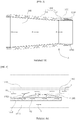
- This combustor includes a duct assembly that is composed of a liner which is in direct contact with hot combustion gas, a flow sleeve surrounding the liner, etc., in which case it is necessary to suitably cool a transition piece or the like. To this end, a portion of the compressed air flowing out of the compressor permeates into an internal annular space through the introduction hole of the flow sleeve to cool the liner (see FIG. 2 ).
- hot combustion gas flows downstream as ignition and combustion are performed in the liner, and thus the surface of the liner is continuously exposed to a high-temperature environment.
- compressed air for cooling flows through the annular space surrounded by the liner and the flow sleeve for film cooling (see FIG. 3 ).
- a separate passage is formed between the seal and a combustion chamber through an introduction hole formed in the surface (see FIG. 4 ).
- EP 2 921 779 A1 discloses a combustion chamber comprising a sleeve section which is at least partly enclosing a duct wall for guiding a cooling gas in a channel between the sleeve section and the duct wall along the outer surface of the duct wall. From the liner protrude a plurality of axially extending ribs for guiding the cooling gas flow in the cooling channel between the duct wall and cooling sleeve. The ribs are circumferentially arranged repeatedly spaced apart by a distance in the circumferential direction.
- EP 2 921 779 A1 also discloses an example in which the ribs comprise apertures which allow a cross flow for a more homogeneous pressure distribution around the duct wall.
- the present disclosure has been made in view of the above-mentioned problem, and an object thereof is to provide a turbulence generating structure capable of avoiding a pressure drop and generating optimum turbulence for enabling compressed air limitedly supplied from a compressor to stay for a maximum time on a liner surface while maximizing a cooling area thereon, thereby generally enhancing liner cooling efficiency, and a gas turbine combustor having the same.
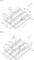
- the first turbulence generator may be configured such that each of the blocks formed on each of the ribs has angled front and rear surfaces and a passage is diagonally formed by the cooling hole.
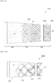
- a plurality of ribs 100 may be arranged and protrude in a spiral form to form a certain angle with the axial direction X, and each of the ribs 100 may include blocks 120 protruding at regular distances in the direction thereof and cooling holes 130 formed between the blocks 120.
Landscapes
- Engineering & Computer Science (AREA)
- Chemical & Material Sciences (AREA)
- Combustion & Propulsion (AREA)
- Mechanical Engineering (AREA)
- General Engineering & Computer Science (AREA)
- Turbine Rotor Nozzle Sealing (AREA)
Claims (11)
- Verwirbelungserzeugungsstruktur zur Auskleidungskühlungsverbesserung für eine Gasturbinenverbrennungsvorrichtung, wobei die Verwirbelungserzeugungsstruktur Folgendes umfasst:eine Auskleidung (1250) undeinen ersten Verwirbelungsgenerator (S10), der von einer Oberfläche eines Teils der Auskleidung (1250) vorsteht und mehrere Stege (100), die in einer Axialrichtung der Auskleidung (1250) angeordnet sind, umfasst, wobei jeder der Stege (100) Blöcke (120) umfasst, die auf dem Steg (100) gebildet sind und in regelmäßigen Abständen in der Axialrichtung angeordnet sind und durch Kühllöcher (130) beabstandet sind, wobei die mehreren Stege (100) Folgendes enthalten:mehrere erste und zweite Sätze benachbarter Stege, die umlaufend um die Auskleidung (1250) verteilt sind, wobeidie Elemente des ersten Satzes benachbarter Stege (100a, 100b) durch einen ersten Durchgangsabstand (L1) getrennt sind, wobei der erste Durchgangsabstand (L1) in einer Umfangsrichtung der Auskleidung (1250) wiederholt wird,die Elemente des zweiten Satzes benachbarter Stege (100b, 100c) durch einen zweiten Durchgangsabstand (L2) getrennt sind, wobei der zweite Durchgangsabstand (L2) in der Umfangsrichtung wiederholt wird, undder erste und der zweite Satz benachbarter Stege genau einen Steg (100b) gemeinsam haben und der erste Durchgangsabstand (L1) größer als der zweite Durchgangsabstand (L2) ist.
- Verwirbelungserzeugungsstruktur nach Anspruch 1, wobei der erste Verwirbelungsgenerator (S10) derart konfiguriert ist, dass jeder der Blöcke (121), die an jedem Steg (100) gebildet sind, angewinkelte Vorder- und Rückseiten besitzt, und derart, dass ein Durchgang durch das Kühlloch (131) diagonal gebildet ist.
- Verwirbelungserzeugungsstruktur nach Anspruch 2, wobei die angewinkelten Oberflächen der Blöcke (121) in Bezug auf den ersten Durchgangsabstand (L1) oder den zweiten Durchgangsabstand (L2) symmetrisch sind.
- Verwirbelungserzeugungsstruktur nach Anspruch 2 oder 3, wobei jede der angewinkelten Oberflächen der Blöcke (121) einen spitzen Winkel mit der Axialrichtung bildet, der mit einer Luftdurchflussrichtung in Beziehung steht.
- Verwirbelungserzeugungsstruktur nach einem der vorhergehenden Ansprüche, wobei der erste Verwirbelungsgenerator (S10) derart konfiguriert ist, dass der erste und der zweite Durchgangsabstand (L1, L2) in der Axialrichtung variieren, wobei der erste und der zweite Durchgangsabstand (L1, L2) einen ersten Bereich der Auskleidung (S12-1) belegen und jeder der Stege (100) einen gebogenen Teil (122c) besitzt, der dem ersten Durchgangsabstand (L1) ermöglicht, sich zu einem zweiten Durchgangsabstand (L2) eines zweiten Bereichs der Auskleidung (S12-2) zu ändern, und dem zweiten Durchgangsabstand (L2) ermöglicht, sich zu einem ersten Durchgangsabstand (L1) des zweiten Bereichs der Auskleidung (S12-2) zu ändern.
- Verwirbelungserzeugungsstruktur nach einem der vorhergehenden Ansprüche, die ferner einen zweiten Verwirbelungsgenerator (S20) umfasst, der aus Blöcken (140) besteht, die von einer Oberfläche eines Teils der Auskleidung (1250), der von der Oberfläche des Teils der Auskleidung, die durch den ersten Verwirbelungsgenerator (S10) belegt ist, getrennt ist, vorstehen, wobei die Blöcke (140) in regelmäßigen Abständen in der Umfangsrichtung der Auskleidung (1250) angeordnet sind, die Blöcke (140) in der Axialrichtung ausgerichtet sind, um einen Kühlraum (230) dazwischen zu definieren, und der erste Verwirbelungsgenerator (S10) und der zweite Verwirbelungsgenerator (S20) gemäß einem Durchfluss der komprimierten Luft (A) zur Kühlung sequenziell angeordnet sind.
- Verwirbelungserzeugungsstruktur nach Anspruch 6, wobei der zweite Verwirbelungsgenerator (S20) derart konfiguriert ist, dass jeder der Blöcke (140) angewinkelte Vorder- und Rückseiten besitzt, und derart, dass ein Durchgang durch den Kühlraum (230) diagonal gebildet ist.
- Verwirbelungserzeugungsstruktur nach Anspruch 6 oder 7, wobei die Blöcke (140) in einem vorgegebenen Abstand umlaufend gebildet sind.
- Verwirbelungserzeugungsstruktur nach einem der vorhergehenden Ansprüche 6-8, wobei der zweite Verwirbelungsgenerator (S20) derart konfiguriert ist, dass jeder der Blöcke (142) eine abgeschrägte Kante (142a), die lediglich bei einer Vorderseite des Blocks (142) gebildet ist oder die an einer Vorderseite und einer Rückseite des Blocks (142) gebildet ist, besitzt.
- Verwirbelungserzeugungsstruktur nach einem der vorhergehenden Ansprüche 6-9, wobei der erste Verwirbelungsgenerator (S10) und der zweite Verwirbelungsgenerator (S20) durch Parameter, die mit einer Strömungsgeschwindigkeit und einer Durchflussmenge der komprimierten Luft (A) zur Kühlung in Beziehung stehen, begrenzt sind.
- Verwirbelungserzeugungsstruktur nach einem der vorhergehenden Ansprüche 6-10, die ferner einen dritten Verwirbelungsgenerator (S30) umfasst, der von einer Oberfläche eines Teils der Auskleidung (1250), der von den Oberflächen der Teile, die durch den ersten und den zweiten Verwirbelungsgenerator (S10, S20) belegt sind, getrennt ist, vorsteht und Stifte (150), die in der Axialrichtung und der Umfangsrichtung der Auskleidung (1250) angeordnet sind, und einen Kühlraum (240), der zwischen den Stiften (150) definiert ist, umfasst, wobei der erste Verwirbelungsgenerator (S10), der zweite Verwirbelungsgenerator (S20) und der dritte Verwirbelungsgenerator (S30) gemäß einem Durchfluss der komprimierten Luft (A) zur Kühlung wahlweise und sequentiell angeordnet sind.
Applications Claiming Priority (1)
| Application Number | Priority Date | Filing Date | Title |
|---|---|---|---|
| KR1020170130105A KR102099307B1 (ko) | 2017-10-11 | 2017-10-11 | 라이너 냉각을 촉진하는 난류 생성 구조 및 이를 포함하는 가스 터빈용 연소기 |
Publications (2)
| Publication Number | Publication Date |
|---|---|
| EP3470737A1 EP3470737A1 (de) | 2019-04-17 |
| EP3470737B1 true EP3470737B1 (de) | 2020-05-13 |
Family
ID=63407091
Family Applications (1)
| Application Number | Title | Priority Date | Filing Date |
|---|---|---|---|
| EP18190909.4A Active EP3470737B1 (de) | 2017-10-11 | 2018-08-27 | Turbulenzerzeugende struktur zur verbesserung der linienkühlung einer gasturbinenbrennkammer |
Country Status (3)
| Country | Link |
|---|---|
| US (1) | US11073283B2 (de) |
| EP (1) | EP3470737B1 (de) |
| KR (1) | KR102099307B1 (de) |
Families Citing this family (7)
| Publication number | Priority date | Publication date | Assignee | Title |
|---|---|---|---|---|
| KR102101488B1 (ko) * | 2018-08-17 | 2020-04-16 | 두산중공업 주식회사 | 연소기 및 이를 포함하는 가스 터빈 |
| US11306918B2 (en) * | 2018-11-02 | 2022-04-19 | Chromalloy Gas Turbine Llc | Turbulator geometry for a combustion liner |
| US10890328B2 (en) * | 2018-11-29 | 2021-01-12 | DOOSAN Heavy Industries Construction Co., LTD | Fin-pin flow guide for efficient transition piece cooling |
| EP3748231B1 (de) * | 2019-06-05 | 2023-08-30 | Siemens Energy Global GmbH & Co. KG | Brenner und brennerspitze |
| CN111520760A (zh) * | 2020-04-10 | 2020-08-11 | 西北工业大学 | 一种冲击/气膜双层壁复合冷却方式的燃烧室火焰筒壁面结构 |
| CN114757115B (zh) * | 2022-03-17 | 2025-06-06 | 中国科学院深圳先进技术研究院 | 压气机的流场数值确定方法、装置、设备及存储介质 |
| KR20260005505A (ko) * | 2024-07-03 | 2026-01-12 | 두산에너빌리티 주식회사 | 연소기 및 이를 포함하는 발전기 |
Family Cites Families (20)
| Publication number | Priority date | Publication date | Assignee | Title |
|---|---|---|---|---|
| US3736747A (en) | 1971-07-09 | 1973-06-05 | G Warren | Combustor |
| US3938323A (en) * | 1971-12-15 | 1976-02-17 | Phillips Petroleum Company | Gas turbine combustor with controlled fuel mixing |
| JPH10200278A (ja) * | 1997-01-13 | 1998-07-31 | Yaskawa Electric Corp | 冷却装置 |
| US6018950A (en) * | 1997-06-13 | 2000-02-01 | Siemens Westinghouse Power Corporation | Combustion turbine modular cooling panel |
| US6098420A (en) * | 1998-03-31 | 2000-08-08 | Sanyo Electric Co., Ltd. | Absorption chiller and heat exchanger tube used the same |
| JP2000088252A (ja) * | 1998-09-11 | 2000-03-31 | Hitachi Ltd | 冷却促進構造を有するガスタービン |
| DE19963374B4 (de) * | 1999-12-28 | 2007-09-13 | Alstom | Vorrichtung zur Kühlung einer, einen Strömungskanal umgebenden Strömungskanalwand mit wenigstens einem Rippenelement |
| EP1413831A1 (de) * | 2002-10-21 | 2004-04-28 | Siemens Aktiengesellschaft | Ringbrennkammern für eine Gasturbine und Gasturbine |
| US7104067B2 (en) | 2002-10-24 | 2006-09-12 | General Electric Company | Combustor liner with inverted turbulators |
| US7007482B2 (en) | 2004-05-28 | 2006-03-07 | Power Systems Mfg., Llc | Combustion liner seal with heat transfer augmentation |
| CN100458344C (zh) * | 2005-12-13 | 2009-02-04 | 金龙精密铜管集团股份有限公司 | 一种电制冷满液式机组用铜冷凝换热管 |
| US20090120093A1 (en) | 2007-09-28 | 2009-05-14 | General Electric Company | Turbulated aft-end liner assembly and cooling method |
| US8109735B2 (en) * | 2008-11-13 | 2012-02-07 | Honeywell International Inc. | Cooled component with a featured surface and related manufacturing method |
| US20100223931A1 (en) * | 2009-03-04 | 2010-09-09 | General Electric Company | Pattern cooled combustor liner |
| US8201412B2 (en) | 2010-09-13 | 2012-06-19 | General Electric Company | Apparatus and method for cooling a combustor |
| US8955330B2 (en) | 2011-03-29 | 2015-02-17 | Siemens Energy, Inc. | Turbine combustion system liner |
| EP2999927B1 (de) * | 2013-05-23 | 2020-01-08 | United Technologies Corporation | Innenverkleidungstafel für einen gasturbinenmotor |
| EP2921779B1 (de) | 2014-03-18 | 2017-12-06 | Ansaldo Energia Switzerland AG | Brennkammer mit Kühlhülse |
| JP6282184B2 (ja) * | 2014-06-19 | 2018-02-21 | 三菱日立パワーシステムズ株式会社 | 伝熱装置及びそれを備えたガスタービン燃焼器 |
| KR101786858B1 (ko) * | 2017-03-15 | 2017-10-18 | 삼중테크 주식회사 | 전열관 및 이를 이용하는 흡수식 냉온수기 |
-
2017
- 2017-10-11 KR KR1020170130105A patent/KR102099307B1/ko active Active
-
2018
- 2018-08-27 EP EP18190909.4A patent/EP3470737B1/de active Active
- 2018-08-27 US US16/112,807 patent/US11073283B2/en active Active
Non-Patent Citations (1)
| Title |
|---|
| None * |
Also Published As
| Publication number | Publication date |
|---|---|
| US20190107054A1 (en) | 2019-04-11 |
| EP3470737A1 (de) | 2019-04-17 |
| KR102099307B1 (ko) | 2020-04-09 |
| US11073283B2 (en) | 2021-07-27 |
| KR20190040680A (ko) | 2019-04-19 |
Similar Documents
| Publication | Publication Date | Title |
|---|---|---|
| EP3470737A1 (de) | Turbulenzerzeugende struktur zur verbesserung der linienkühlung | |
| US10731856B2 (en) | Duct assembly including helicoidal structure and gas turbine combustor including the same | |
| US11079112B2 (en) | Combustor and gas turbine including the same | |
| US10514171B2 (en) | 3D non-axisymmetric combustor liner | |
| KR101986729B1 (ko) | 실 영역 집중냉각을 위한 냉각유로 구조 및 이를 포함하는 가스 터빈용 연소기 | |
| US20190285278A1 (en) | Fuel supply device for gas turbines and fuel nozzle and gas turbine having the same | |
| US11608985B2 (en) | Combustor and gas turbine including the same | |
| KR20190048908A (ko) | 연소기 및 이를 포함하는 가스 터빈 | |
| KR20190040667A (ko) | 연소기 및 이를 포함하는 가스 터빈 | |
| US9103552B2 (en) | Burner assembly including a fuel distribution ring with a slot and recess | |
| US20190086091A1 (en) | Turbine engine assembly including a rotating detonation combustor | |
| KR102135442B1 (ko) | 링 세그먼트 및 이를 포함하는 가스 터빈 | |
| US11280270B2 (en) | Igniter assembly for a gas turbine combustor | |
| US11131457B2 (en) | Combustor for gas turbine | |
| US11204167B2 (en) | Gas turbine combustor | |
| US10865656B2 (en) | Turbine blade ring segment, and turbine and gas turbine including the same | |
| EP3477203B1 (de) | Brennkammer und gasturbine damit | |
| KR101807586B1 (ko) | 가스 터빈 연소기용 연료 노즐 | |
| KR102051988B1 (ko) | 이중관 라이너 내부 유동가이드를 포함하는 가스 터빈 엔진의 연소기, 및 이를 포함하는 가스터빈 | |
| KR102377720B1 (ko) | 압력 강하가 개선된 라이너 냉각구조 및 이를 포함하는 가스터빈용 연소기 | |
| KR20190041702A (ko) | 버킷의 쓰로틀 플레이트 결합구조와 이를 포함하는 회전체 및 가스터빈 | |
| KR102088048B1 (ko) | 연소기 및 이를 포함하는 가스 터빈 | |
| KR20230039941A (ko) | 링 세그먼트, 이를 포함하는 회전 기계 | |
| KR20230040674A (ko) | 링 세그먼트, 이를 포함하는 회전 기계 | |
| KR20190045745A (ko) | 덕트 조립체, 이를 포함하는 연소기 및 가스 터빈 |
Legal Events
| Date | Code | Title | Description |
|---|---|---|---|
| PUAI | Public reference made under article 153(3) epc to a published international application that has entered the european phase |
Free format text: ORIGINAL CODE: 0009012 |
|
| STAA | Information on the status of an ep patent application or granted ep patent |
Free format text: STATUS: REQUEST FOR EXAMINATION WAS MADE |
|
| 17P | Request for examination filed |
Effective date: 20180827 |
|
| AK | Designated contracting states |
Kind code of ref document: A1 Designated state(s): AL AT BE BG CH CY CZ DE DK EE ES FI FR GB GR HR HU IE IS IT LI LT LU LV MC MK MT NL NO PL PT RO RS SE SI SK SM TR |
|
| AX | Request for extension of the european patent |
Extension state: BA ME |
|
| RBV | Designated contracting states (corrected) |
Designated state(s): AL AT BE BG CH CY CZ DE DK EE ES FI FR GB GR HR HU IE IS IT LI LT LU LV MC MK MT NL NO PL PT RO RS SE SI SK SM TR |
|
| GRAP | Despatch of communication of intention to grant a patent |
Free format text: ORIGINAL CODE: EPIDOSNIGR1 |
|
| STAA | Information on the status of an ep patent application or granted ep patent |
Free format text: STATUS: GRANT OF PATENT IS INTENDED |
|
| INTG | Intention to grant announced |
Effective date: 20191202 |
|
| GRAS | Grant fee paid |
Free format text: ORIGINAL CODE: EPIDOSNIGR3 |
|
| GRAJ | Information related to disapproval of communication of intention to grant by the applicant or resumption of examination proceedings by the epo deleted |
Free format text: ORIGINAL CODE: EPIDOSDIGR1 |
|
| GRAL | Information related to payment of fee for publishing/printing deleted |
Free format text: ORIGINAL CODE: EPIDOSDIGR3 |
|
| STAA | Information on the status of an ep patent application or granted ep patent |
Free format text: STATUS: REQUEST FOR EXAMINATION WAS MADE |
|
| GRAR | Information related to intention to grant a patent recorded |
Free format text: ORIGINAL CODE: EPIDOSNIGR71 |
|
| STAA | Information on the status of an ep patent application or granted ep patent |
Free format text: STATUS: GRANT OF PATENT IS INTENDED |
|
| GRAA | (expected) grant |
Free format text: ORIGINAL CODE: 0009210 |
|
| STAA | Information on the status of an ep patent application or granted ep patent |
Free format text: STATUS: THE PATENT HAS BEEN GRANTED |
|
| INTC | Intention to grant announced (deleted) | ||
| INTG | Intention to grant announced |
Effective date: 20200331 |
|
| AK | Designated contracting states |
Kind code of ref document: B1 Designated state(s): AL AT BE BG CH CY CZ DE DK EE ES FI FR GB GR HR HU IE IS IT LI LT LU LV MC MK MT NL NO PL PT RO RS SE SI SK SM TR |
|
| REG | Reference to a national code |
Ref country code: GB Ref legal event code: FG4D |
|
| REG | Reference to a national code |
Ref country code: CH Ref legal event code: EP |
|
| REG | Reference to a national code |
Ref country code: DE Ref legal event code: R096 Ref document number: 602018004505 Country of ref document: DE |
|
| REG | Reference to a national code |
Ref country code: AT Ref legal event code: REF Ref document number: 1270784 Country of ref document: AT Kind code of ref document: T Effective date: 20200615 |
|
| REG | Reference to a national code |
Ref country code: LT Ref legal event code: MG4D |
|
| REG | Reference to a national code |
Ref country code: NL Ref legal event code: MP Effective date: 20200513 |
|
| PG25 | Lapsed in a contracting state [announced via postgrant information from national office to epo] |
Ref country code: LT Free format text: LAPSE BECAUSE OF FAILURE TO SUBMIT A TRANSLATION OF THE DESCRIPTION OR TO PAY THE FEE WITHIN THE PRESCRIBED TIME-LIMIT Effective date: 20200513 Ref country code: FI Free format text: LAPSE BECAUSE OF FAILURE TO SUBMIT A TRANSLATION OF THE DESCRIPTION OR TO PAY THE FEE WITHIN THE PRESCRIBED TIME-LIMIT Effective date: 20200513 Ref country code: PT Free format text: LAPSE BECAUSE OF FAILURE TO SUBMIT A TRANSLATION OF THE DESCRIPTION OR TO PAY THE FEE WITHIN THE PRESCRIBED TIME-LIMIT Effective date: 20200914 Ref country code: IS Free format text: LAPSE BECAUSE OF FAILURE TO SUBMIT A TRANSLATION OF THE DESCRIPTION OR TO PAY THE FEE WITHIN THE PRESCRIBED TIME-LIMIT Effective date: 20200913 Ref country code: SE Free format text: LAPSE BECAUSE OF FAILURE TO SUBMIT A TRANSLATION OF THE DESCRIPTION OR TO PAY THE FEE WITHIN THE PRESCRIBED TIME-LIMIT Effective date: 20200513 Ref country code: NO Free format text: LAPSE BECAUSE OF FAILURE TO SUBMIT A TRANSLATION OF THE DESCRIPTION OR TO PAY THE FEE WITHIN THE PRESCRIBED TIME-LIMIT Effective date: 20200813 Ref country code: GR Free format text: LAPSE BECAUSE OF FAILURE TO SUBMIT A TRANSLATION OF THE DESCRIPTION OR TO PAY THE FEE WITHIN THE PRESCRIBED TIME-LIMIT Effective date: 20200814 |
|
| PG25 | Lapsed in a contracting state [announced via postgrant information from national office to epo] |
Ref country code: HR Free format text: LAPSE BECAUSE OF FAILURE TO SUBMIT A TRANSLATION OF THE DESCRIPTION OR TO PAY THE FEE WITHIN THE PRESCRIBED TIME-LIMIT Effective date: 20200513 Ref country code: RS Free format text: LAPSE BECAUSE OF FAILURE TO SUBMIT A TRANSLATION OF THE DESCRIPTION OR TO PAY THE FEE WITHIN THE PRESCRIBED TIME-LIMIT Effective date: 20200513 Ref country code: BG Free format text: LAPSE BECAUSE OF FAILURE TO SUBMIT A TRANSLATION OF THE DESCRIPTION OR TO PAY THE FEE WITHIN THE PRESCRIBED TIME-LIMIT Effective date: 20200813 Ref country code: LV Free format text: LAPSE BECAUSE OF FAILURE TO SUBMIT A TRANSLATION OF THE DESCRIPTION OR TO PAY THE FEE WITHIN THE PRESCRIBED TIME-LIMIT Effective date: 20200513 |
|
| REG | Reference to a national code |
Ref country code: AT Ref legal event code: MK05 Ref document number: 1270784 Country of ref document: AT Kind code of ref document: T Effective date: 20200513 |
|
| PG25 | Lapsed in a contracting state [announced via postgrant information from national office to epo] |
Ref country code: AL Free format text: LAPSE BECAUSE OF FAILURE TO SUBMIT A TRANSLATION OF THE DESCRIPTION OR TO PAY THE FEE WITHIN THE PRESCRIBED TIME-LIMIT Effective date: 20200513 Ref country code: NL Free format text: LAPSE BECAUSE OF FAILURE TO SUBMIT A TRANSLATION OF THE DESCRIPTION OR TO PAY THE FEE WITHIN THE PRESCRIBED TIME-LIMIT Effective date: 20200513 |
|
| PG25 | Lapsed in a contracting state [announced via postgrant information from national office to epo] |
Ref country code: CZ Free format text: LAPSE BECAUSE OF FAILURE TO SUBMIT A TRANSLATION OF THE DESCRIPTION OR TO PAY THE FEE WITHIN THE PRESCRIBED TIME-LIMIT Effective date: 20200513 Ref country code: ES Free format text: LAPSE BECAUSE OF FAILURE TO SUBMIT A TRANSLATION OF THE DESCRIPTION OR TO PAY THE FEE WITHIN THE PRESCRIBED TIME-LIMIT Effective date: 20200513 Ref country code: IT Free format text: LAPSE BECAUSE OF FAILURE TO SUBMIT A TRANSLATION OF THE DESCRIPTION OR TO PAY THE FEE WITHIN THE PRESCRIBED TIME-LIMIT Effective date: 20200513 Ref country code: RO Free format text: LAPSE BECAUSE OF FAILURE TO SUBMIT A TRANSLATION OF THE DESCRIPTION OR TO PAY THE FEE WITHIN THE PRESCRIBED TIME-LIMIT Effective date: 20200513 Ref country code: AT Free format text: LAPSE BECAUSE OF FAILURE TO SUBMIT A TRANSLATION OF THE DESCRIPTION OR TO PAY THE FEE WITHIN THE PRESCRIBED TIME-LIMIT Effective date: 20200513 Ref country code: EE Free format text: LAPSE BECAUSE OF FAILURE TO SUBMIT A TRANSLATION OF THE DESCRIPTION OR TO PAY THE FEE WITHIN THE PRESCRIBED TIME-LIMIT Effective date: 20200513 Ref country code: SM Free format text: LAPSE BECAUSE OF FAILURE TO SUBMIT A TRANSLATION OF THE DESCRIPTION OR TO PAY THE FEE WITHIN THE PRESCRIBED TIME-LIMIT Effective date: 20200513 Ref country code: DK Free format text: LAPSE BECAUSE OF FAILURE TO SUBMIT A TRANSLATION OF THE DESCRIPTION OR TO PAY THE FEE WITHIN THE PRESCRIBED TIME-LIMIT Effective date: 20200513 |
|
| REG | Reference to a national code |
Ref country code: DE Ref legal event code: R097 Ref document number: 602018004505 Country of ref document: DE |
|
| PG25 | Lapsed in a contracting state [announced via postgrant information from national office to epo] |
Ref country code: SK Free format text: LAPSE BECAUSE OF FAILURE TO SUBMIT A TRANSLATION OF THE DESCRIPTION OR TO PAY THE FEE WITHIN THE PRESCRIBED TIME-LIMIT Effective date: 20200513 Ref country code: PL Free format text: LAPSE BECAUSE OF FAILURE TO SUBMIT A TRANSLATION OF THE DESCRIPTION OR TO PAY THE FEE WITHIN THE PRESCRIBED TIME-LIMIT Effective date: 20200513 |
|
| PLBE | No opposition filed within time limit |
Free format text: ORIGINAL CODE: 0009261 |
|
| STAA | Information on the status of an ep patent application or granted ep patent |
Free format text: STATUS: NO OPPOSITION FILED WITHIN TIME LIMIT |
|
| PG25 | Lapsed in a contracting state [announced via postgrant information from national office to epo] |
Ref country code: MC Free format text: LAPSE BECAUSE OF FAILURE TO SUBMIT A TRANSLATION OF THE DESCRIPTION OR TO PAY THE FEE WITHIN THE PRESCRIBED TIME-LIMIT Effective date: 20200513 |
|
| 26N | No opposition filed |
Effective date: 20210216 |
|
| PG25 | Lapsed in a contracting state [announced via postgrant information from national office to epo] |
Ref country code: LU Free format text: LAPSE BECAUSE OF NON-PAYMENT OF DUE FEES Effective date: 20200827 |
|
| REG | Reference to a national code |
Ref country code: BE Ref legal event code: MM Effective date: 20200831 |
|
| PG25 | Lapsed in a contracting state [announced via postgrant information from national office to epo] |
Ref country code: SI Free format text: LAPSE BECAUSE OF FAILURE TO SUBMIT A TRANSLATION OF THE DESCRIPTION OR TO PAY THE FEE WITHIN THE PRESCRIBED TIME-LIMIT Effective date: 20200513 |
|
| PG25 | Lapsed in a contracting state [announced via postgrant information from national office to epo] |
Ref country code: FR Free format text: LAPSE BECAUSE OF NON-PAYMENT OF DUE FEES Effective date: 20200831 |
|
| PG25 | Lapsed in a contracting state [announced via postgrant information from national office to epo] |
Ref country code: IE Free format text: LAPSE BECAUSE OF NON-PAYMENT OF DUE FEES Effective date: 20200827 Ref country code: BE Free format text: LAPSE BECAUSE OF NON-PAYMENT OF DUE FEES Effective date: 20200831 |
|
| REG | Reference to a national code |
Ref country code: CH Ref legal event code: PL |
|
| PG25 | Lapsed in a contracting state [announced via postgrant information from national office to epo] |
Ref country code: LI Free format text: LAPSE BECAUSE OF NON-PAYMENT OF DUE FEES Effective date: 20210831 Ref country code: CH Free format text: LAPSE BECAUSE OF NON-PAYMENT OF DUE FEES Effective date: 20210831 |
|
| PG25 | Lapsed in a contracting state [announced via postgrant information from national office to epo] |
Ref country code: TR Free format text: LAPSE BECAUSE OF FAILURE TO SUBMIT A TRANSLATION OF THE DESCRIPTION OR TO PAY THE FEE WITHIN THE PRESCRIBED TIME-LIMIT Effective date: 20200513 Ref country code: MT Free format text: LAPSE BECAUSE OF FAILURE TO SUBMIT A TRANSLATION OF THE DESCRIPTION OR TO PAY THE FEE WITHIN THE PRESCRIBED TIME-LIMIT Effective date: 20200513 Ref country code: CY Free format text: LAPSE BECAUSE OF FAILURE TO SUBMIT A TRANSLATION OF THE DESCRIPTION OR TO PAY THE FEE WITHIN THE PRESCRIBED TIME-LIMIT Effective date: 20200513 |
|
| PG25 | Lapsed in a contracting state [announced via postgrant information from national office to epo] |
Ref country code: MK Free format text: LAPSE BECAUSE OF FAILURE TO SUBMIT A TRANSLATION OF THE DESCRIPTION OR TO PAY THE FEE WITHIN THE PRESCRIBED TIME-LIMIT Effective date: 20200513 |
|
| GBPC | Gb: european patent ceased through non-payment of renewal fee |
Effective date: 20220827 |
|
| PG25 | Lapsed in a contracting state [announced via postgrant information from national office to epo] |
Ref country code: GB Free format text: LAPSE BECAUSE OF NON-PAYMENT OF DUE FEES Effective date: 20220827 |
|
| PGFP | Annual fee paid to national office [announced via postgrant information from national office to epo] |
Ref country code: DE Payment date: 20250702 Year of fee payment: 8 |