EP3470622A1 - Car frame traveling type shield tunnel wall post-grouting detection apparatus - Google Patents
Car frame traveling type shield tunnel wall post-grouting detection apparatus Download PDFInfo
- Publication number
- EP3470622A1 EP3470622A1 EP18821101.5A EP18821101A EP3470622A1 EP 3470622 A1 EP3470622 A1 EP 3470622A1 EP 18821101 A EP18821101 A EP 18821101A EP 3470622 A1 EP3470622 A1 EP 3470622A1
- Authority
- EP
- European Patent Office
- Prior art keywords
- assembly type
- type track
- grouting
- shield
- radar
- Prior art date
- Legal status (The legal status is an assumption and is not a legal conclusion. Google has not performed a legal analysis and makes no representation as to the accuracy of the status listed.)
- Pending
Links
Images

Classifications
-
- E—FIXED CONSTRUCTIONS
- E21—EARTH OR ROCK DRILLING; MINING
- E21D—SHAFTS; TUNNELS; GALLERIES; LARGE UNDERGROUND CHAMBERS
- E21D9/00—Tunnels or galleries, with or without linings; Methods or apparatus for making thereof; Layout of tunnels or galleries
- E21D9/003—Arrangement of measuring or indicating devices for use during driving of tunnels, e.g. for guiding machines
-
- E—FIXED CONSTRUCTIONS
- E21—EARTH OR ROCK DRILLING; MINING
- E21D—SHAFTS; TUNNELS; GALLERIES; LARGE UNDERGROUND CHAMBERS
- E21D11/00—Lining tunnels, galleries or other underground cavities, e.g. large underground chambers; Linings therefor; Making such linings in situ, e.g. by assembling
- E21D11/04—Lining with building materials
- E21D11/10—Lining with building materials with concrete cast in situ; Shuttering also lost shutterings, e.g. made of blocks, of metal plates or other equipment adapted therefor
-
- E—FIXED CONSTRUCTIONS
- E21—EARTH OR ROCK DRILLING; MINING
- E21D—SHAFTS; TUNNELS; GALLERIES; LARGE UNDERGROUND CHAMBERS
- E21D11/00—Lining tunnels, galleries or other underground cavities, e.g. large underground chambers; Linings therefor; Making such linings in situ, e.g. by assembling
- E21D11/04—Lining with building materials
- E21D11/10—Lining with building materials with concrete cast in situ; Shuttering also lost shutterings, e.g. made of blocks, of metal plates or other equipment adapted therefor
- E21D11/105—Transport or application of concrete specially adapted for the lining of tunnels or galleries ; Backfilling the space between main building element and the surrounding rock, e.g. with concrete
-
- E—FIXED CONSTRUCTIONS
- E21—EARTH OR ROCK DRILLING; MINING
- E21D—SHAFTS; TUNNELS; GALLERIES; LARGE UNDERGROUND CHAMBERS
- E21D9/00—Tunnels or galleries, with or without linings; Methods or apparatus for making thereof; Layout of tunnels or galleries
- E21D9/06—Making by using a driving shield, i.e. advanced by pushing means bearing against the already placed lining
-
- E—FIXED CONSTRUCTIONS
- E21—EARTH OR ROCK DRILLING; MINING
- E21F—SAFETY DEVICES, TRANSPORT, FILLING-UP, RESCUE, VENTILATION, OR DRAINING IN OR OF MINES OR TUNNELS
- E21F17/00—Methods or devices for use in mines or tunnels, not covered elsewhere
- E21F17/18—Special adaptations of signalling or alarm devices
-
- G—PHYSICS
- G01—MEASURING; TESTING
- G01N—INVESTIGATING OR ANALYSING MATERIALS BY DETERMINING THEIR CHEMICAL OR PHYSICAL PROPERTIES
- G01N33/00—Investigating or analysing materials by specific methods not covered by groups G01N1/00 - G01N31/00
- G01N33/38—Concrete; Lime; Mortar; Gypsum; Bricks; Ceramics; Glass
- G01N33/383—Concrete or cement
-
- G—PHYSICS
- G01—MEASURING; TESTING
- G01S—RADIO DIRECTION-FINDING; RADIO NAVIGATION; DETERMINING DISTANCE OR VELOCITY BY USE OF RADIO WAVES; LOCATING OR PRESENCE-DETECTING BY USE OF THE REFLECTION OR RERADIATION OF RADIO WAVES; ANALOGOUS ARRANGEMENTS USING OTHER WAVES
- G01S13/00—Systems using the reflection or reradiation of radio waves, e.g. radar systems; Analogous systems using reflection or reradiation of waves whose nature or wavelength is irrelevant or unspecified
- G01S13/88—Radar or analogous systems specially adapted for specific applications
- G01S13/885—Radar or analogous systems specially adapted for specific applications for ground probing
Definitions
- the present invention belongs to the field of backfill grouting and cavity detection during construction of a shield tunnel, and specifically, to a loaded-to-frame detection equipment for backfill grouting of a shield tunnel.
- a grouting form is not easy to control; and for shield tail structure void estimation and grouting parameter setting, there is no experience to follow.
- ground surface settlement is caused in a construction stage, and existing tunnels and bridges are deformed greatly.
- water leakage and mud leakage in a tunnel will be caused or a partial tunnel structure will be damaged; or an internal structure (such as the subway track) of a tunnel will be vertically distorted and deformed, thereby affecting the normal operation of the tunnel, and causing some potential threats to the safety of a tunnel structure and the safety and comfort of the subway train operation.
- the synchronous grouting amount is generally determined according to manual experience, and a shape and a filling degree of a grouting body at a rear part of a segment cannot be determined effectively, and therefore the grouting operation cannot be effectively guided in real time. Therefore, it is necessary to conduct special research on grout mechanics and diffusion characteristics, prediction and detection of actual grouting injection amount, real-time detection of an actual grouting effect, and the like.
- quality detection of backfill grouting of a shield in China mainly includes manual field measurement and recording performed after tunnel construction is completed. Then, subsequent processing is performed indoors. At this time, the ground surface settlement has occurred for a long time, and a disease caused by a grouting defect has generated significant economic losses, and therefore the detection significance is relatively small at this time.
- manual detection is easily restricted by field conditions and has relatively low stability. Equipment for real-time automatic detection of backfill grouting urgently needs to be developed.
- An objective of the present invention is to propose a loaded-to-frame detection equipment for backfill grouting of a shield tunnel.
- the loaded-to-frame detection equipment for backfill grouting of a shield tunnel proposed in the present invention includes a ground penetrating radar 1, a servo controller 2, a drive motor and reducer 3, a transmission mechanism 4, a radar acquisition box 5, a support 6, an assembly type track 7, a belt wheel 9, and a conveyor belt 10, where the assembly type track 7 is of an arched structure, the ground penetrating radar 1 is carried above the assembly type track 7 through the support 6, and the ground penetrating radar 1 can move along the assembly type track at a uniform speed and perform discontinuous detection at equal time intervals through the support 6; the transmission mechanism 4 and the drive motor and reducer 3 are fastened to one side of the assembly type track 7, the transmission mechanism 4 is connected to the drive motor and reducer 3, the servo controller 2 is fastened onto a side surface of the assembly type track 7, the servo controller 2 is connected to the drive motor and reducer, and several belt wheels 9 are fastened below the assembly type track 7; one end of the conveyor belt 10 is connected to the support 6, the other end thereof
- an antenna detection frequency of the carried radar is between 300 MHz and 900 MHz, so as to improve a detection effect of a backfill grouting body.
- a movement range of the ground penetrating radar 1 can satisfy a detection requirement of 15° to 360°
- a motion mode of the ground penetrating radar 1 includes moving at a uniform speed and performing discontinuous pausing at an equal time interval, and each time a shield performs tunneling by one ring, the ground penetrating radar 1 performs circular grouting detection of the shield.
- the radar acquisition box 5 is connected to an operation room computer by using a network cable; and visual radar image analysis software is configured on the operation room computer for analysis to implement visual layered display of a grouting body.
- the assembly type track is formed by connecting several assembly type track sections in sequence.
- Reference numbers in the figure: 1 is a grounding penetrating radar, 2 is a servo controller, 3 is a drive motor and reducer, 4 is a transmission mechanism, 5 is a radar acquisition box, 6 is a support, 7 is an assembly type track, 8 is shield machine assembly interface, 9 is a belt wheel, and 10 is a conveyor belt.
- an apparatus includes a ground penetrating radar 1, a servo controller 2, a drive motor and reducer 3, a transmission mechanism 4, a radar acquisition box 5, a support 6, an assembly type track 7, a belt wheel 9, and a conveyor belt 10.
- the ground penetrating radar 1 is connected to the conveyor belt 10 by using a support plate, the conveyor belt performs a circular motion through traction by the drive motor and reducer 3 and the transmission mechanism 4, and a motion mode thereof is controlled by the servo controller 2.
- the ground penetrating radar 1 obtains a radar signal and transmits the radar signal to the radar acquisition box 5 by using a coaxial cable, and transmits, by using a network cable, the radar signal to an operation room computer to perform data analysis.
- FIG. 2 is a diagram of sections of an assembly type track according to the present invention. A number of phases required for the sections of the assembly type track are calculated according to a requirement of an actual detection angle.
- the assembly type track 7 is formed by connecting several assembly type track sections in sequence.
- a circular detection angle is first determined according to a detection requirement and operating space of a shield, and the angle is controlled between 20° to 360°.
- a number of required sections are calculated according to a requirement of an actual detection angle and a length of the assembly section shown in FIG. 2 , and field assembly is performed to form integrated equipment shown in FIG. 1 .
- the integrated equipment shown in FIG. 1 is carried on a shield machine frame through shield machine assembly interfaces 8, to form an integrated equipment.
Landscapes
- Engineering & Computer Science (AREA)
- Mining & Mineral Resources (AREA)
- Life Sciences & Earth Sciences (AREA)
- Structural Engineering (AREA)
- Geology (AREA)
- General Life Sciences & Earth Sciences (AREA)
- Geochemistry & Mineralogy (AREA)
- Architecture (AREA)
- Physics & Mathematics (AREA)
- Remote Sensing (AREA)
- Radar, Positioning & Navigation (AREA)
- Electromagnetism (AREA)
- Civil Engineering (AREA)
- General Physics & Mathematics (AREA)
- Environmental & Geological Engineering (AREA)
- Computer Networks & Wireless Communication (AREA)
- Chemical & Material Sciences (AREA)
- Health & Medical Sciences (AREA)
- Medicinal Chemistry (AREA)
- General Health & Medical Sciences (AREA)
- Immunology (AREA)
- Pathology (AREA)
- Biochemistry (AREA)
- Analytical Chemistry (AREA)
- Food Science & Technology (AREA)
- Ceramic Engineering (AREA)
- Lining And Supports For Tunnels (AREA)
- Radar Systems Or Details Thereof (AREA)
Abstract
Description
- The present invention belongs to the field of backfill grouting and cavity detection during construction of a shield tunnel, and specifically, to a loaded-to-frame detection equipment for backfill grouting of a shield tunnel.
- In recent years, as China strengthens infrastructure investment, China's traffic construction has achieved rapid development, and the construction and research of highway tunnels, especially long tunnels, have also achieved rapid development. At present, China has become a country that has the largest number of tunnel projects in the world and whose tunnel projects are the most complex and has developed fastest. Based on a principle "head and tail protection and frequent grouting" in shield construction, radar detection equipment is researched and developed to implement detection of a backfill grouting thickness of a shield. Peripheral deformation control is of great significance to ensure construction and surrounding environment safety. At present, synchronous grouting of a shield tunnel is an important measure to control stratum deformation and protect existing tunnels and bridges and surrounding environments. However, a grouting form is not easy to control; and for shield tail structure void estimation and grouting parameter setting, there is no experience to follow. In addition, during curve crossing, it is difficult to perform quality control of tunnel construction, thereby easily causing a correction gap. If improper control is performed, ground surface settlement is caused in a construction stage, and existing tunnels and bridges are deformed greatly. In an operation stage, water leakage and mud leakage in a tunnel will be caused or a partial tunnel structure will be damaged; or an internal structure (such as the subway track) of a tunnel will be vertically distorted and deformed, thereby affecting the normal operation of the tunnel, and causing some potential threats to the safety of a tunnel structure and the safety and comfort of the subway train operation. Further, the operation of various structures around and on the ground is affected, causing huge economic losses and even serious social adverse effects. Conventionally, the synchronous grouting amount is generally determined according to manual experience, and a shape and a filling degree of a grouting body at a rear part of a segment cannot be determined effectively, and therefore the grouting operation cannot be effectively guided in real time. Therefore, it is necessary to conduct special research on grout mechanics and diffusion characteristics, prediction and detection of actual grouting injection amount, real-time detection of an actual grouting effect, and the like.
- At present, quality detection of backfill grouting of a shield in China mainly includes manual field measurement and recording performed after tunnel construction is completed. Then, subsequent processing is performed indoors. At this time, the ground surface settlement has occurred for a long time, and a disease caused by a grouting defect has generated significant economic losses, and therefore the detection significance is relatively small at this time. In addition, manual detection is easily restricted by field conditions and has relatively low stability. Equipment for real-time automatic detection of backfill grouting urgently needs to be developed.
- An objective of the present invention is to propose a loaded-to-frame detection equipment for backfill grouting of a shield tunnel.
- The loaded-to-frame detection equipment for backfill grouting of a shield tunnel proposed in the present invention includes a ground penetrating radar 1, a
servo controller 2, a drive motor and reducer 3, atransmission mechanism 4, aradar acquisition box 5, asupport 6, an assembly type track 7, abelt wheel 9, and aconveyor belt 10, where the assembly type track 7 is of an arched structure, the ground penetrating radar 1 is carried above the assembly type track 7 through thesupport 6, and the ground penetrating radar 1 can move along the assembly type track at a uniform speed and perform discontinuous detection at equal time intervals through thesupport 6; thetransmission mechanism 4 and the drive motor and reducer 3 are fastened to one side of the assembly type track 7, thetransmission mechanism 4 is connected to the drive motor and reducer 3, theservo controller 2 is fastened onto a side surface of the assembly type track 7, theservo controller 2 is connected to the drive motor and reducer, andseveral belt wheels 9 are fastened below the assembly type track 7; one end of theconveyor belt 10 is connected to thesupport 6, the other end thereof bypasses above the assembly type track 7, passes thetransmission mechanism 4, and passes through theseveral belt wheels 9 in sequence, and after arriving at a bottom part of the other side of the assembly type track 7, theconveyor belt 10 bypasses above the other side of the assembly type track 7 and is connected to thesupport 6, so that the conveyor belt forms a closed loop; theradar acquisition box 5 is fastened to thesupport 6, and theradar acquisition box 5 is connected to the ground penetrating radar 1 by using a coaxial cable; several shieldmachine assembly interfaces 8 are disposed below the assembly type track 7; the loaded-to-frame detection equipment for backfill grouting of a shield tunnel is carried on a shield machine frame through the shieldmachine assembly interfaces 8; and under control of theservo controller 2, the transmission mechanism is driven by the drive motor and reducer 3, the transmission mechanism drives theconveyor belt 10 and thebelt wheel 9, and theconveyor belt 10 drives, by driving thesupport 8, the ground penetrating radar 1 to perform a circular motion. - In the present invention, an antenna detection frequency of the carried radar is between 300 MHz and 900 MHz, so as to improve a detection effect of a backfill grouting body.
- In the present invention, according to front clearance and operation requirements of a shield machine, a movement range of the ground penetrating radar 1 can satisfy a detection requirement of 15° to 360°, a motion mode of the ground penetrating radar 1 includes moving at a uniform speed and performing discontinuous pausing at an equal time interval, and each time a shield performs tunneling by one ring, the ground penetrating radar 1 performs circular grouting detection of the shield.
- In the present invention, the
radar acquisition box 5 is connected to an operation room computer by using a network cable; and visual radar image analysis software is configured on the operation room computer for analysis to implement visual layered display of a grouting body. - In the present invention, the assembly type track is formed by connecting several assembly type track sections in sequence.
- Beneficial effects of the present invention are as follows:
- (1) A requirement for real-time detection of backfill grouting of a shield tunnel is satisfied, and a backfill grouting construction level is improved: The detection equipment is carried in the front of a first frame of a shield machine, and moves following the shield machine, so as to implement real-time automatic detection of backfill grouting slurry; and grouting parameter adjustment and grouting slurry supplementation are implemented to assist backfill grouting construction, so as to improve the backfill grouting construction level.
- (2) Detection quality of backfill grouting is improved: In the present invention, an arc track is designed, and the ground penetrating radar performs circular detection along the track. This improves detection stability and a positioning effect of a radar wave compared with manual detection.
- (3) Safety convenience: Detection personnel can adjust a detection range of a fracture surface by increasing a number of assembly type sections, and an entire detection process is performed automatically, and has characteristics of safety and convenience.
- (4) High image processing real-time performance: After the detection is completed, a form of a grouting body can be synchronously displayed by using self-developed visual software, so as to shorten indoor processing time of previous manual detection.
-
-
FIG. 1 a schematic structural diagram of loaded-to-frame detection equipment for backfill grouting of a shield tunnel developed by the present invention; -
FIG. 2 is a diagram of sections of an assembly type track; -
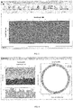
FIG. 3 is a diagram of real-time processing of a radar signal by a signal processing unit by comprehensively using methods such as DEWOW, direct current removal, air layer removal, background removal and filtering, AGC/ACC, and track equalization; -
FIG. 4 is a visual display diagram of backfill grouting obtained through field detection, where (a) is an expanded view of layer thicknesses of a grouting body and a soil layer at a segment; (b) is a grouting fullness coefficient diagram (a percentage in this figure is a ratio of an actual detection thickness of a grouting body to a designed value), and (c) is a visual display diagram of backfill grouting distribution; and -
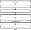
FIG. 5 is a path diagram of an technology implementation. - Reference numbers in the
figure: 1 is a grounding penetrating radar, 2 is a servo controller, 3 is a drive motor and reducer, 4 is a transmission mechanism, 5 is a radar acquisition box, 6 is a support, 7 is an assembly type track, 8 is shield machine assembly interface, 9 is a belt wheel, and 10 is a conveyor belt. - The following further describes the present invention with reference to the accompanying diagrams.
- Embodiment 1: As shown in
FIG. 1 , an apparatus includes a ground penetrating radar 1, aservo controller 2, a drive motor and reducer 3, atransmission mechanism 4, aradar acquisition box 5, asupport 6, an assembly type track 7, abelt wheel 9, and aconveyor belt 10. The ground penetrating radar 1 is connected to theconveyor belt 10 by using a support plate, the conveyor belt performs a circular motion through traction by the drive motor and reducer 3 and thetransmission mechanism 4, and a motion mode thereof is controlled by theservo controller 2. The ground penetrating radar 1 obtains a radar signal and transmits the radar signal to theradar acquisition box 5 by using a coaxial cable, and transmits, by using a network cable, the radar signal to an operation room computer to perform data analysis. -
FIG. 2 is a diagram of sections of an assembly type track according to the present invention. A number of phases required for the sections of the assembly type track are calculated according to a requirement of an actual detection angle. The assembly type track 7 is formed by connecting several assembly type track sections in sequence. - Referring to
FIG. 5 , in the present invention, a circular detection angle is first determined according to a detection requirement and operating space of a shield, and the angle is controlled between 20° to 360°. A number of required sections are calculated according to a requirement of an actual detection angle and a length of the assembly section shown inFIG. 2 , and field assembly is performed to form integrated equipment shown inFIG. 1 . After the assembly is completed, the integrated equipment shown inFIG. 1 is carried on a shield machine frame through shieldmachine assembly interfaces 8, to form an integrated equipment. - The equipment may move following a shield after being integrated, and performs circular detection on each segment. In a detection process, a
radar acquisition box 5 collects radar data and sends the radar data back to an operation room computer in real time by using a network cable. Real-time processing is performed on a radar signal in real time by a signal processing module shown inFIG. 3 by comprehensively using methods such as DEWOW, direct current removal, air layer removal, background removal and filtering, AGC/ACC, and track equalization), so as to obtain a visual diagram of a grouting layer shown inFIG. 4 , where (a) is an expanded view of layer thicknesses of a grouting body and a soil layer at a segment; (b) is a grouting fullness coefficient diagram (a percentage in this figure is a ratio of an actual detection thickness of a grouting body to a designed value), and (c) is a visual display diagram of backfill grouting distribution.
Claims (5)
- A loaded-to-frame detection equipment for backfill grouting of a shield tunnel, comprising a ground penetrating radar (1), a servo controller (2), a drive motor and reducer (3), a transmission mechanism (4), a radar acquisition box (5), a support (6), an assembly type track (7), a belt wheel (9), and a conveyor belt (10), wherein the assembly type track (7) is of an arched structure, the ground penetrating radar (1) is carried above the assembly type track (7) through the support (6), and the ground penetrating radar (1) can move back and forth along the assembly type track through the support (6); the transmission mechanism (4) and the drive motor and reducer (3) are fastened to one side of the assembly type track (7), the transmission mechanism (4) is connected to the drive motor and reducer (3), the servo controller (2) is fastened onto a side surface of the assembly type track (7), the servo controller (2) is connected to the drive motor and reducer, and several belt wheels (9) are fastened below the assembly type track (7); one end of the conveyor belt (10) is connected to the support (6), the other end thereof bypasses above the assembly type track (7), passes the transmission mechanism (4), and passes through the several belt wheels (9) in sequence, and after arriving at a bottom part of the other side of the assembly type track (7), the conveyor belt (10) bypasses above the other side of the assembly type track (7) and is connected to the support (6), so that the conveyor belt forms a closed loop; the radar acquisition box (5) is fastened to the support (6), and the radar acquisition box is connected to the ground penetrating radar by using an optical fiber; several shield machine assembly interfaces (8) are disposed below the assembly type track (7); the loaded-to-frame detection equipment for backfill grouting of a shield tunnel is carried on a shield machine frame through the shield machine assembly interfaces (8); and under control of the servo controller (2), the transmission mechanism is driven by the drive motor and reducer (3), the transmission mechanism drives the conveyor belt (10) and the belt wheel (9), and the conveyor belt (10) drives, by driving the support (6), the ground penetrating radar (1) to perform a circular motion.
- The loaded-to-frame detection equipment for backfill grouting of a shield tunnel according to claim 1, wherein an antenna detection frequency of the ground penetrating radar (1) is 300 MHz to 900 MHz.
- The loaded-to-frame detection equipment for backfill grouting of a shield tunnel according to claim 1, wherein according to front clearance and operation requirements of a shield machine, a movement range of the ground penetrating radar (1) can satisfy a detection requirement of 15° to 360°, a motion mode of the ground penetrating radar (1) comprises moving at a uniform speed and performing discontinuous pausing at an equal time interval, and each time a shield performs tunneling by one ring, the ground penetrating radar (1) performs circular grouting detection of the shield.
- The loaded-to-frame detection equipment for backfill grouting of a shield tunnel according to claim 1, wherein the radar acquisition box (5) is connected to an operation room computer by using a network cable; and visual radar image analysis software is configured on the operation room computer for analysis to implement visual layered display of a grouting body.
- The loaded-to-frame detection equipment for backfill grouting of a shield tunnel according to claim 1, wherein the assembly type track is formed by connecting several assembly type track sections in sequence.
Applications Claiming Priority (2)
| Application Number | Priority Date | Filing Date | Title |
|---|---|---|---|
| CN201710472728.8A CN107120120B (en) | 2017-06-21 | 2017-06-21 | Frame accompanying type shield tunnel wall grouting detection equipment |
| PCT/CN2018/082763 WO2018233354A1 (en) | 2017-06-21 | 2018-04-12 | Behind-type shield tunnel wall grouting inspection equipment |
Publications (2)
| Publication Number | Publication Date |
|---|---|
| EP3470622A1 true EP3470622A1 (en) | 2019-04-17 |
| EP3470622A4 EP3470622A4 (en) | 2019-09-04 |
Family
ID=59720124
Family Applications (1)
| Application Number | Title | Priority Date | Filing Date |
|---|---|---|---|
| EP18821101.5A Pending EP3470622A4 (en) | 2017-06-21 | 2018-04-12 | VEHICLE CHASSIS DISPLACEMENT TYPE POST-JOINING WINDOW PROTECTION TUNNEL DETECTION APPARATUS |
Country Status (4)
| Country | Link |
|---|---|
| US (1) | US11181633B2 (en) |
| EP (1) | EP3470622A4 (en) |
| CN (1) | CN107120120B (en) |
| WO (1) | WO2018233354A1 (en) |
Families Citing this family (39)
| Publication number | Priority date | Publication date | Assignee | Title |
|---|---|---|---|---|
| CN107120120B (en) * | 2017-06-21 | 2019-10-01 | 同济大学 | Frame accompanying type shield tunnel wall grouting detection equipment |
| CN108087022B (en) * | 2017-12-08 | 2024-04-26 | 中国电子科技集团公司第五十一研究所 | Shield tunnel detection device |
| CN108286433B (en) * | 2018-02-09 | 2020-12-04 | 安徽恒诺机电科技有限公司 | Shield tunnel detection mechanism and using method thereof |
| CN108643921A (en) * | 2018-04-18 | 2018-10-12 | 同济大学 | Shield-tunneling construction quality machine-carried type double freedom detection method and detection platform |
| CN108918670A (en) * | 2018-06-07 | 2018-11-30 | 南宁中铁广发轨道装备有限公司 | A kind of shield tunnel construction slip casting real-time detection platform |
| CN109490878B (en) * | 2018-12-29 | 2024-04-26 | 安徽省城建设计研究总院股份有限公司 | Tunnel special ground penetrating radar detection device |
| CN109799327A (en) * | 2019-03-08 | 2019-05-24 | 西南交通大学 | A kind of visual shield tunnel construction detection of grouting effects experimental rig and method |
| CN110542886B (en) * | 2019-09-06 | 2023-01-24 | 上海市基础工程集团有限公司 | Ground penetrating radar special machine tool for shield tunnel grouting detection |
| CN111125961A (en) * | 2019-12-27 | 2020-05-08 | 中国水利水电第七工程局有限公司 | A refined step-by-step control method for bridge settlement and deformation in subway tunnel construction |
| CN116201565B (en) * | 2020-03-06 | 2026-04-03 | 宏润建设集团股份有限公司 | Evaluation methods based on analysis of shield tunneling construction |
| CN111650584B (en) * | 2020-05-14 | 2023-09-15 | 中国科学院武汉岩土力学研究所 | A method and equipment for detecting the grouting reinforcement effect behind the shield tunnel wall |
| CN112253177B (en) * | 2020-07-26 | 2025-06-13 | 江西省高速公路投资集团有限责任公司南昌西管理中心 | Tunnel lining equipment |
| CN112611332A (en) * | 2020-09-28 | 2021-04-06 | 同济大学 | Circumferential double-freedom-degree detection control device for shield wall back grouting |
| CN112523780B (en) * | 2020-12-01 | 2022-11-29 | 中铁十二局集团有限公司 | Soft rock tunnel lining vault anti-hollowing active monitoring construction method |
| CN112780307B (en) * | 2021-01-06 | 2023-01-24 | 中铁十六局集团有限公司 | A type of tunnel vault grouting device with mold and its construction method |
| CN113177270B (en) * | 2021-03-17 | 2022-02-15 | 北京交通大学 | A real-time calculation method for formation deformation caused by shield attitude |
| CN113295579B (en) * | 2021-03-19 | 2023-05-05 | 无锡地铁集团有限公司 | Device and method for testing synchronous grouting slurry diffusion visualization behind shield wall |
| CN113279783B (en) * | 2021-05-28 | 2022-04-01 | 苏州中车建设工程有限公司 | Back-grouting equipment for tunnel construction shield |
| CN113323692B (en) * | 2021-06-22 | 2023-11-03 | 中铁五局集团第一工程有限责任公司 | A grouting platform for inclined shaft branch holes |
| CN113482633A (en) * | 2021-08-12 | 2021-10-08 | 中铁十二局集团有限公司 | Construction method for shield to pass through existing subway station in water-rich silt stratum |
| CN114019134B (en) * | 2021-08-23 | 2023-05-05 | 长安大学 | Combined type shield tunnel wall back grouting simulation device and test method |
| CN113944473B (en) * | 2021-09-26 | 2023-05-02 | 中铁四局集团有限公司 | Convolution spraying construction method for increasing ductility of pile foundation of operation subway station |
| CN114047290B (en) * | 2021-10-26 | 2024-06-18 | 中国铁道科学研究院集团有限公司基础设施检测研究所 | Portable tunnel lining detection device |
| CN113914876B (en) * | 2021-11-08 | 2024-04-12 | 郑州地铁集团有限公司 | A small shield tunnel backfilling device |
| CN114135297B (en) * | 2021-11-30 | 2023-01-13 | 山东大学 | Rock mass structure detection system and method for integrated carrying of rock drilling jumbo |
| CN114370278B (en) * | 2021-12-02 | 2023-06-30 | 山东大学 | Device and method for detecting grouting effect behind shield tunnel segment and wall |
| CN114370282B (en) * | 2021-12-07 | 2023-09-05 | 山东大学 | Shield tunnel wall rear synchronous grouting body three-dimensional detection equipment based on elastic wave method |
| CN114217088B (en) * | 2021-12-25 | 2024-03-26 | 中铁工程装备集团有限公司 | Automatic cooperative detection method for grouting outside pipe sheet of shield tunneling machine |
| CN114414438B (en) * | 2022-01-24 | 2024-01-26 | 中国矿业大学 | An identification method for detecting grouting diffusion range based on proton magnetometer |
| CN114673557B (en) * | 2022-03-28 | 2025-05-16 | 中铁隧道局集团有限公司 | Intelligent detection device and method for tunnel shotcrete quality |
| CN115198791B (en) * | 2022-05-20 | 2024-02-02 | 中交隧道工程局有限公司 | Bottom grouting technology for installation of substructure components of large-diameter shield tunnels |
| CN115199303B (en) * | 2022-05-20 | 2024-12-03 | 中交隧道工程局有限公司 | Construction method of large-size arc-shaped parts in shield tunnel of urban railway |
| CN114876514A (en) * | 2022-05-25 | 2022-08-09 | 中煤科工集团重庆研究院有限公司 | Control method based on guniting robot |
| CN114970346B (en) * | 2022-05-27 | 2025-06-03 | 天津市地下铁道集团有限公司 | Prediction method of medium distribution behind shield tunnel wall based on ground penetrating radar and GAN |
| CN114934787B (en) * | 2022-06-08 | 2024-08-23 | 中国国家铁路集团有限公司 | Visual tunnel two lining arch portion longitudinal pouring plump device |
| CN115753516B (en) * | 2022-10-13 | 2025-09-19 | 中铁十四局集团有限公司 | Test device and test method for testing filling property of double liquid slurries |
| CN115824813B (en) * | 2023-02-23 | 2023-05-09 | 叙镇铁路有限责任公司 | Test device and method for testing range of surrounding rock plastic zone caused by tunnel excavation |
| CN119044956B (en) * | 2024-07-15 | 2025-04-18 | 济南城建集团有限公司 | A tunnel excavation section geological radar data acquisition system and detection method |
| CN121095256B (en) * | 2025-11-12 | 2026-02-13 | 山西世德孙家沟煤矿有限公司 | Data Processing Methods and Systems for Coal Mine Water Control |
Family Cites Families (14)
| Publication number | Priority date | Publication date | Assignee | Title |
|---|---|---|---|---|
| JPH0274796A (en) * | 1988-09-09 | 1990-03-14 | Oomotogumi:Kk | Covering method for shield tunnel with cast-in-place concrete |
| CN100445516C (en) * | 2006-12-14 | 2008-12-24 | 同济大学 | Settlement Control Method of Shield Tunnel Based on Ground Penetrating Radar |
| JP5324528B2 (en) * | 2010-06-24 | 2013-10-23 | 日本国土開発株式会社 | Concrete filling detection device and concrete filling device |
| CN101943003B (en) * | 2010-08-16 | 2012-07-11 | 上海地铁盾构设备工程有限公司 | Shield Construction System Based on Ground Penetrating Radar |
| CN103123252B (en) * | 2012-02-10 | 2015-08-05 | 南京大学 | Duct pieces of shield tunnel back synchronous injection many reference amounts real-time monitoring system |
| KR101281242B1 (en) * | 2012-08-31 | 2013-07-02 | (주)동아컨설턴트 | Grouting methode |
| CN203050719U (en) * | 2013-02-05 | 2013-07-10 | 北京首尔工程技术有限公司 | Tunnel arch springing circumferential high-pressure ejecting and reinforcing construction device |
| CN103573269B (en) * | 2013-11-13 | 2015-07-15 | 上海建科工程咨询有限公司 | Shield tunnel grouting layer performance detection method |
| CN103713335B (en) * | 2014-01-07 | 2015-04-22 | 山东大学 | Comprehensive advance geological detection system carried by tunnel boring machine |
| CN104989423B (en) * | 2015-06-11 | 2017-05-24 | 同济大学 | Visual single-circle shield tunneling synchronous grouting slurry diffusion mode study platform and application of platform |
| CN105545325B (en) * | 2015-12-29 | 2018-04-06 | 上海隧道工程有限公司 | Class rectangle shield synchronization slip casting visual Simulation pilot system and method |
| CN106199597B (en) * | 2016-08-16 | 2023-05-30 | 上海交通大学 | Mechanical device and detection method for automatic detection of shield tunnel lining construction quality |
| CN206223984U (en) * | 2016-08-16 | 2017-06-06 | 中铁十六局集团北京轨道交通工程建设有限公司 | A kind of mechanical device of automatic detection shield tunnel liner construction quality |
| CN107120120B (en) * | 2017-06-21 | 2019-10-01 | 同济大学 | Frame accompanying type shield tunnel wall grouting detection equipment |
-
2017
- 2017-06-21 CN CN201710472728.8A patent/CN107120120B/en active Active
-
2018
- 2018-04-12 EP EP18821101.5A patent/EP3470622A4/en active Pending
- 2018-04-12 WO PCT/CN2018/082763 patent/WO2018233354A1/en not_active Ceased
-
2019
- 2019-05-13 US US16/410,625 patent/US11181633B2/en active Active
Also Published As
| Publication number | Publication date |
|---|---|
| US11181633B2 (en) | 2021-11-23 |
| CN107120120B (en) | 2019-10-01 |
| CN107120120A (en) | 2017-09-01 |
| US20190330984A1 (en) | 2019-10-31 |
| EP3470622A4 (en) | 2019-09-04 |
| WO2018233354A1 (en) | 2018-12-27 |
Similar Documents
| Publication | Publication Date | Title |
|---|---|---|
| US11181633B2 (en) | Loaded-to-frame detection equipment and method for backfill grouting of shield tunnel | |
| US11555912B2 (en) | Automatic wall climbing type radar photoelectric robot system for non-destructive inspection and diagnosis of damages of bridge and tunnel structure | |
| CN108828589B (en) | High-precision rapid vehicle-mounted detection method and device for lining quality of subway shield tunnel | |
| CN107765339B (en) | Combined test method for roadway surrounding rock stability | |
| CN104678426B (en) | Active source 3-D seismics advance geology exploration device and method in rock tunnel(ling) machine | |
| CN209132427U (en) | A kind of tunnel geology radar quickly detects robot device | |
| CN108519596A (en) | A Segment Hidden Crack Identification Method Based on Matching Pursuit and Wavelet Transform | |
| CN114370278B (en) | Device and method for detecting grouting effect behind shield tunnel segment and wall | |
| CN105628893B (en) | Model test device for simulating karst covering soil subsidence caused by subway vibration in karst region | |
| CN102607477A (en) | Full-face vehicular detection method for railway tunnel lining and device | |
| CN1975112A (en) | Shield tunnel subsidence control method based on exploring radar | |
| CN107333046A (en) | Collecting method and Tunnel testing car | |
| CN115290752B (en) | Device for actively adjusting microwave parameters to cause rotational fracturing of deep hard rock and method of using the device | |
| CN201247045Y (en) | Measuring system for cantalever digging handpiece location posture | |
| CN102230915A (en) | Device and method for flaw detection of small crawler-type rails based on three-way ultrasonic diffraction | |
| CN115754254A (en) | Automatic control test method and device for improving muck | |
| CN108643921A (en) | Shield-tunneling construction quality machine-carried type double freedom detection method and detection platform | |
| US12624630B2 (en) | Long-term monitoring apparatus and method for surrounding rock fracture evolution process triggered by multiple-source dynamic disturbances | |
| CN113219522A (en) | Advanced earthquake prediction observation system and method carried on shield | |
| CN107121566B (en) | A kind of train monitoring method and system measured in real time based on bodywork surface wind speed unmanned plane | |
| CN114791632A (en) | Tunnel geological safety advanced ultra-deep detection vehicle | |
| CN108254746A (en) | A kind of road quality dynamic monitor based on sanitation cart | |
| CN111474542A (en) | A Method of Realizing 3D Detection Using Geographical Radar Spatial Scanning | |
| CN205022584U (en) | Tunnel state detects car | |
| CN108710122A (en) | A kind of horn antenna and its detection method to highway tunnel lining |
Legal Events
| Date | Code | Title | Description |
|---|---|---|---|
| STAA | Information on the status of an ep patent application or granted ep patent |
Free format text: STATUS: THE INTERNATIONAL PUBLICATION HAS BEEN MADE |
|
| PUAI | Public reference made under article 153(3) epc to a published international application that has entered the european phase |
Free format text: ORIGINAL CODE: 0009012 |
|
| STAA | Information on the status of an ep patent application or granted ep patent |
Free format text: STATUS: REQUEST FOR EXAMINATION WAS MADE |
|
| 17P | Request for examination filed |
Effective date: 20190111 |
|
| AK | Designated contracting states |
Kind code of ref document: A1 Designated state(s): AL AT BE BG CH CY CZ DE DK EE ES FI FR GB GR HR HU IE IS IT LI LT LU LV MC MK MT NL NO PL PT RO RS SE SI SK SM TR |
|
| AX | Request for extension of the european patent |
Extension state: BA ME |
|
| RIN1 | Information on inventor provided before grant (corrected) |
Inventor name: QIN, HUI Inventor name: ZHOU, YUNXIANG Inventor name: XIE, XIONGYAO Inventor name: CHEN, YIFAN Inventor name: ZHOU, BIAO |
|
| A4 | Supplementary search report drawn up and despatched |
Effective date: 20190801 |
|
| RIC1 | Information provided on ipc code assigned before grant |
Ipc: G01S 13/88 20060101ALI20190726BHEP Ipc: E21D 9/06 20060101ALI20190726BHEP Ipc: E21D 9/00 20060101AFI20190726BHEP Ipc: G01N 33/38 20060101ALI20190726BHEP |
|
| DAV | Request for validation of the european patent (deleted) | ||
| DAX | Request for extension of the european patent (deleted) | ||
| STAA | Information on the status of an ep patent application or granted ep patent |
Free format text: STATUS: EXAMINATION IS IN PROGRESS |
|
| 17Q | First examination report despatched |
Effective date: 20220302 |