EP3470603B1 - Method for erecting structural elements of building/construction of monolithic reinforced concrete and technological equipment to implement it - Google Patents
Method for erecting structural elements of building/construction of monolithic reinforced concrete and technological equipment to implement it Download PDFInfo
- Publication number
- EP3470603B1 EP3470603B1 EP18176874.8A EP18176874A EP3470603B1 EP 3470603 B1 EP3470603 B1 EP 3470603B1 EP 18176874 A EP18176874 A EP 18176874A EP 3470603 B1 EP3470603 B1 EP 3470603B1
- Authority
- EP
- European Patent Office
- Prior art keywords
- structures
- vertical structures
- erected
- panels
- poured
- Prior art date
- Legal status (The legal status is an assumption and is not a legal conclusion. Google has not performed a legal analysis and makes no representation as to the accuracy of the status listed.)
- Active
Links
Images






Classifications
-
- E—FIXED CONSTRUCTIONS
- E04—BUILDING
- E04G—SCAFFOLDING; FORMS; SHUTTERING; BUILDING IMPLEMENTS OR AIDS, OR THEIR USE; HANDLING BUILDING MATERIALS ON THE SITE; REPAIRING, BREAKING-UP OR OTHER WORK ON EXISTING BUILDINGS
- E04G17/00—Connecting or other auxiliary members for forms, falsework structures, or shutterings
- E04G17/06—Tying means; Spacers ; Devices for extracting or inserting wall ties
-
- E—FIXED CONSTRUCTIONS
- E04—BUILDING
- E04G—SCAFFOLDING; FORMS; SHUTTERING; BUILDING IMPLEMENTS OR AIDS, OR THEIR USE; HANDLING BUILDING MATERIALS ON THE SITE; REPAIRING, BREAKING-UP OR OTHER WORK ON EXISTING BUILDINGS
- E04G11/00—Forms, shutterings, or falsework for making walls, floors, ceilings, or roofs
- E04G11/06—Forms, shutterings, or falsework for making walls, floors, ceilings, or roofs for walls, e.g. curved end panels for wall shutterings; filler elements for wall shutterings; shutterings for vertical ducts
- E04G11/20—Movable forms; Movable forms for moulding cylindrical, conical or hyperbolical structures; Templates serving as forms for positioning blocks or the like
- E04G11/28—Climbing forms, i.e. forms which are not in contact with the poured concrete during lifting from layer to layer and which are anchored in the hardened concrete
-
- E—FIXED CONSTRUCTIONS
- E04—BUILDING
- E04G—SCAFFOLDING; FORMS; SHUTTERING; BUILDING IMPLEMENTS OR AIDS, OR THEIR USE; HANDLING BUILDING MATERIALS ON THE SITE; REPAIRING, BREAKING-UP OR OTHER WORK ON EXISTING BUILDINGS
- E04G9/00—Forming or shuttering elements for general use
- E04G9/02—Forming boards or similar elements
- E04G2009/028—Forming boards or similar elements with reinforcing ribs on the underside
Definitions
- the present group of inventions is related to civil engineering and can be used in erection of multi-storey buildings/constructions.
- MD 4161 relates to construction and can be used in the erection of multi-storey cast-in-situ buildings.
- the process for erection of cast-in-situ building includes the erection of cast-in-situ piece of the building: floor slab of the entire building - vertical structures of the overlying stage/floor of the entire building.
- the basic principle of the process erection of the floor slab of the stage/floor of the building and, after setting of concrete floor slab of this stage/floor, concrete-filling of vertical structures of the next stage/floor of the entire building - time curing of the poured concrete up to the attainment of the working strength - erection of another floor slab, etc.
- the formwork is based on the stacked vertical structures of the building.
- Production tooling includes: the formwork transfer mechanism, the reinforcement binding device, the vertical formwork panel, the set of angular vertical formwork panels, the set of opening forming panels, the tightening device and the floor slab formwork girder. The result is to increase the strength properties of the erected buildings, reduce the period of construction, building materials saving, the possibility of mechanization and automation of technological processes.
- RU 2078884 relates to construction and can be used in the construction of multi-storey monolithic buildings.
- US 4076778 relates to a climbing formwork for use in the erection of reinforced concrete structures in which the raising of the formwork from storey to storey is carried out by the use of movable vertically extending members the height of which when fully extended is in excess of the height of two storeys of a building to be erected, the members being maintained in their correct vertical positions by supporting tubes set into the concrete of the structure.
- the members carry between them beams or the like for supporting the outer forms and preferably some or all of the inner forms used for pouring the structure and are raised to a height equivalent to that of one storey of the structure after the completion of the pouring of the concrete of a storey.
- the vertically extending members are preferably in the form of double acting hydraulic cylinders having a piston extendable under hydraulic pressure, the extension of the piston being utilized for raising the forms.
- the vertically extending members may be of constant length and raised by means of climbing jacks.
- Method under the preferred embodiment includes erection of the building monolithic segment consisting of floor structure of the whole building and vertical structures of the upper tier/storey of the whole building.
- Main principle of the method erecting the tier/storey floor structure of the whole building; following setting of concrete of said floor structure, pouring concrete of vertical structures of the next tier/storey of the whole building; curing the poured concrete until the design strength is achieved; erecting subsequent floor structure, etc.
- formwork rests on the already poured vertical structures of building.
- Technological equipment comprises, without limitation, travelling formwork and vertical shuttering panels. Travelling formwork includes lifting jacks with props, where U-shaped jack frames are installed.
- Posts of said jack frames are equipped with bearing plates. Frames located on both sides of the being erected vertical structures are connected together by rigid links. On bearing plates of said jack frame posts, carriages are mounted with possibility of travelling across said being erected vertical structures with vertical shuttering panels installed on them. During concreting, jack frames rest on vertical shuttering panels installed on the underlying vertical structures. Following the required strength of concrete is attained, jack frames are relocated to rest upon props of lifting jacks, and formwork is lifted to the next tier/storey.
- the present group of inventions is directed toward solution of following tasks: reduction of time for erection of buildings/constructions of monolithic reinforced concrete; reduction of material and labor costs.
- the set task is resolved by the method for erecting vertical structures of building/construction of monolithic reinforced concrete including process steps as defined in claim 1.
- the vertical structures can be erected simultaneously for the whole building/construction.
- the set task is resolved by the method for erecting multilayer vertical structures of building/construction of monolithic reinforced concrete including process steps as defined in claim 3.
- panels can be installed with holes performed in their decks, where sleeves of elastic material are inserted. Following adjustment of width of molding cavity of the base (constructional) layer, reinforcing rods are inserted in holes with protruding ends located on both sides of the plane of panels. Following removal of panels and prior molding the next layer, a mesh cage is secured on the inserted reinforcing rods.
- Vertical multilayer structures can be erected simultaneously for the whole building/construction.
- the set task is resolved by the method for erecting the "floor structure - vertical structure" segment of building/construction of monolithic reinforced concrete including process steps as defined in claim 7.
- the set task is resolved by the method for erecting the "floor structure-multilayer wall" segment of building/construction of monolithic reinforced concrete including process steps as defined in claim 9.
- panels can be installed with holes performed in their decks, where sleeves of elastic material are inserted. Following adjustment of width of molding cavity of the base (constructional) layer, reinforcing rods are inserted in holes with protruding ends located on both sides of the plane of panels. Following removal of panels and prior molding of the next layer, mesh cage is secured on the inserted reinforcing rods.
- the set task is resolved also by a travelling formwork according to claim 13.
- Extendible supports of jack frames can be provided with motion drive and can be installed on each post of jack frames in guides located at an angle (preferably 45 degrees) to the being erected vertical structures.
- guides for motion of extendible supports located on posts of each U-shaped jack frame are arranged in opposite directions from posts along the being erected vertical structures.
- Rotation drive of the shell can be installed on a pad located on its top end and contains a gear wheel engaging a gear ring secured on outer surface in the top part of the lifting jack prop.
- a vertical shuttering panel for erection of multilayer structures, which contains bearing frame with an edge profiles around the panel perimeter, a deck secured on said frame with holes performed in it, where sleeves of elastic material are inserted.
- Extendible supports installed on posts of jack frames allow relocation of travelling formwork on the poured vertical structures and extraction of lifting jacks to continue performance of works.
- Application of removable recess-forming cages hanged prior concreting on the vertical shuttering panels, as well as panels with holes in their decks for inserting reinforcing rods to secure mesh cage prior concreting of the next layer makes it possible to improve bonding of layers of vertical structures. It increases reliability and quality of construction works.
- travelling formwork comprises lifting jacks with props 1, where U-shaped jack frames 2 are installed on.
- guides 4 are secured, where holders 6 of the vertical shuttering panels 7 are installed with motor drive providing possibility of their motion across the being erected vertical structures 5.
- extendible supports 8 are installed moveably.
- shells 9 are installed freely with possibility of rotation and vertical motion. Lower end of each shell 9 is located in the base of the lower (end side) arm of lifting jack.
- Posts 3 of adjacent jack frames 2 located on each side of the being erected vertical structures 5 are connected with each other by rigid links 10.
- Travelling formwork includes also vertical shuttering panels 7 connected rigidly with each other and secured on holders 6 of jack frames 2. Each said panel 7 contains bearing frame with an edge profile around the panel perimeter.
- Extendible supports 8 of jack frames 2 are provided with motion drive and are installed on each post 3 of jack frames 2 in guides 11 located at an angle (preferably 45 degrees) to the being erected vertical structures 5.
- guides 11 are directed in opposite sides from posts 3 along the being erected vertical structures 5. It is evident that extendible supports 8 can be located only on the one of posts 3 of jack frames 2. In this case, extendible supports 8 on adjacent jack frames 2 will be located in the staggered order along the being erected vertical structures 5.
- extendible supports 8 can be executed in the form of outriggers of the truck crane (supports of extendible, folding, pivotable and extendible, pivotable and folding types, etc.) and located on posts 3.
- Rotation drive of the shell 9 is installed on a pad located on its top end and contains gear wheel 12 engaging gear ring 13 secured on outer surface in the top part of the lifting jack prop 1.
- Travelling formwork comprises also vertical shuttering panels 7 containing bearing frame containing edge profiles around the panel perimeter.
- In edge profiles of the vertical shuttering panel holes for fixing elements to connect with other panels can be performed.
- In the panel deck and bearing frame elements holes for tightening devices can be performed.
- Panel can be sized for the whole height of tier/storey.
- panels 15 can be used with holes 17 performed in their decks 16, where sleeves of elastic material are inserted.
- panels 7 can be used with removable recess-forming cages 18 hanged on them from the inner side.
- Single-layer vertical structures are erected as follows.
- Lifting jacks containing props 1 enclosed in shells 9 with U-shaped jack frames 2 provided with extendible supports 8 and installed on these props 1 are mounted on the already erected structures 5.
- Posts 3 of adjacent jack frames 2 located on each side of the being erected vertical structures are connected with each other by rigid links 10.
- Reinforcement cages of vertical structures are installed for the whole height of tier/storey and are secured to the protruding reinforcement of previously erected structures.
- Formwork panels 7 containing brackets 14 are secured to holders 6, and all panels 7 located in single plane are connected rigidly with each other. Width of molding cavity is adjusted by movement of holders 6 in guides 4.
- Panels located in parallel on the opposite side of reinforcement cage of the being erected vertical structures are connected by means of tightening devices.
- Multilayer vertical structures are erected as follows.
- the formwork panels 7 are moved away from the molded multilayer surface, props 1 of lifting jacks are placed resting on the already erected base (constructional) layer of vertical structure 5, U-shaped jack frames 2 are raised with formwork on the next tier/storey and the cycle of erection of the multilayer vertical structures is repeated.
- the removable recess-forming cages 18 are hanged on the inner surface of the formwork panels 7 and removed prior molding of the last (outer) layer.
- Vertical structures can be erected simultaneously for the whole building/construction. Under another embodiment ( Figs. 14 , 15 ), panels 15 ( Fig.
- the "floor structure - vertical structure” segment of building/constructions is erected of monolithic reinforced concrete as follows.
- Lifting jacks containing props 1 enclosed in shells 9 with U-shaped jack frames 2 provided with extendible supports 8 and installed on said props 1 are mounted on the already erected structures 5.
- Posts 3 of adjacent jack frames 2 located on each side of the being erected vertical structures are connected with each other by rigid links 10.
- the floor structure formwork 21 with reinforcement cages is mounted and reinforcement cages of vertical structures for the whole height of tier/storey are installed. Said reinforcement cages are secured to protruding reinforcement of previously erected vertical structures and floor structure.
- Formwork panels 7 containing brackets 14 are secured to holders 6, and all panels 7 located in single plane are connected rigidly with each other with their bottom part located at the level of the top of the floor structure formwork.
- Width of molding cavity is adjusted by movement of holders 6 in guides 4.
- Panels 7 located in parallel on the opposite side of reinforcement cage of the being erected vertical structures are connected by means of tightening devices. Concrete of floor structure is poured and at the final stage of its setting concrete is poured in molding cavities of the being erected vertical structures. Reciprocating and rotational or only rotational motion is imparted to shells 9 enclosing props 1 of lifting jacks.
- U-shaped jack frames 2 are laid resting on the poured vertical structures 5 (constructional layer) by means of extendible supports 8; props 1 of lifting jacks with their enclosing shells 9 are extracted from said vertical structures, while cavities formed in these structures are filled with concrete, and the formwork panels are moved away from the molded surface.
- Props 1 of lifting jacks are placed resting on the already erected structures, U-shaped jack frames 2 are raised with formwork on the next tier/storey and the cycle of erection of the said building segment is repeated.
- Floor structure and vertical structures can be erected simultaneously for the whole building/construction.
- the "floor structure -multilayer wall” segment of building/construction of monolithic reinforced concrete is erected as follows.
- the formwork panels 7 are moved away from the molded multilayer surface, props 1 of lifting jacks are placed resting on the erected base (constructional) layer of vertical structure, U-shaped jack frames 2 are raised with formwork on the next tier/storey and the cycle of erection of the building/construction part is repeated.
- Possible embodiments of the method for erecting multilayer vertical structures are disclosed above in respective section of the present patent specification.
- Floor structure and multilayer vertical structures can be erected simultaneously for the whole building/construction.
- Utilization of inventions makes it possible to reduce consumption of materials for technological equipment and power costs for this equipment relocation. Time required for erection of buildings/constructions with multilayer vertical structures is reduced. When works are carried out simultaneously at the whole building/construction, just as it is specified in the family patent, creation of the monolithic building segment including floor slab structure of building and vertical structures of the upper tier/storey is ensured. Furthermore, rigidity and strength properties of the erected buildings/constructions are improved, which makes it possible to utilize inventions efficiently during construction activities in seismic regions.
Landscapes
- Engineering & Computer Science (AREA)
- Architecture (AREA)
- Mechanical Engineering (AREA)
- Civil Engineering (AREA)
- Structural Engineering (AREA)
- Forms Removed On Construction Sites Or Auxiliary Members Thereof (AREA)
- Conveying And Assembling Of Building Elements In Situ (AREA)
Description
- The present group of inventions is related to civil engineering and can be used in erection of multi-storey buildings/constructions.
- MD 4161 relates to construction and can be used in the erection of multi-storey cast-in-situ buildings. The process for erection of cast-in-situ building includes the erection of cast-in-situ piece of the building: floor slab of the entire building - vertical structures of the overlying stage/floor of the entire building. The basic principle of the process: erection of the floor slab of the stage/floor of the building and, after setting of concrete floor slab of this stage/floor, concrete-filling of vertical structures of the next stage/floor of the entire building - time curing of the poured concrete up to the attainment of the working strength - erection of another floor slab, etc. In the execution of works the formwork is based on the stacked vertical structures of the building. Production tooling includes: the formwork transfer mechanism, the reinforcement binding device, the vertical formwork panel, the set of angular vertical formwork panels, the set of opening forming panels, the tightening device and the floor slab formwork girder. The result is to increase the strength properties of the erected buildings, reduce the period of construction, building materials saving, the possibility of mechanization and automation of technological processes.
-
RU 2078884 -
US 4076778 relates to a climbing formwork for use in the erection of reinforced concrete structures in which the raising of the formwork from storey to storey is carried out by the use of movable vertically extending members the height of which when fully extended is in excess of the height of two storeys of a building to be erected, the members being maintained in their correct vertical positions by supporting tubes set into the concrete of the structure. The members carry between them beams or the like for supporting the outer forms and preferably some or all of the inner forms used for pouring the structure and are raised to a height equivalent to that of one storey of the structure after the completion of the pouring of the concrete of a storey. The vertically extending members are preferably in the form of double acting hydraulic cylinders having a piston extendable under hydraulic pressure, the extension of the piston being utilized for raising the forms. Alternatively the vertically extending members may be of constant length and raised by means of climbing jacks. - Method under the preferred embodiment includes erection of the building monolithic segment consisting of floor structure of the whole building and vertical structures of the upper tier/storey of the whole building. Main principle of the method: erecting the tier/storey floor structure of the whole building; following setting of concrete of said floor structure, pouring concrete of vertical structures of the next tier/storey of the whole building; curing the poured concrete until the design strength is achieved; erecting subsequent floor structure, etc. During performance of works, formwork rests on the already poured vertical structures of building. Technological equipment comprises, without limitation, travelling formwork and vertical shuttering panels. Travelling formwork includes lifting jacks with props, where U-shaped jack frames are installed.
- Posts of said jack frames are equipped with bearing plates. Frames located on both sides of the being erected vertical structures are connected together by rigid links. On bearing plates of said jack frame posts, carriages are mounted with possibility of travelling across said being erected vertical structures with vertical shuttering panels installed on them. During concreting, jack frames rest on vertical shuttering panels installed on the underlying vertical structures. Following the required strength of concrete is attained, jack frames are relocated to rest upon props of lifting jacks, and formwork is lifted to the next tier/storey.
- The fact that jack frames during performance of works rest upon vertical shuttering panels imposes increased requirements to the strength properties of panels. It results in excessive consumption of metal during manufacturing of the panel frames, increased power consumption for relocation of formwork. Erection of multilayer vertical structures using known travelling formwork requires some time for the poured concrete to attain necessary strength in order to make it possible to re-rest jack frames on lifting jacks, which are installed on the already erected vertical structures, and to mold a cavity for the new layer. It extends the time of construction.
- The present group of inventions is directed toward solution of following tasks: reduction of time for erection of buildings/constructions of monolithic reinforced concrete; reduction of material and labor costs.
- The set task is resolved by the method for erecting vertical structures of building/construction of monolithic reinforced concrete including process steps as defined in claim 1.
- The vertical structures can be erected simultaneously for the whole building/construction.
- The set task is resolved by the method for erecting multilayer vertical structures of building/construction of monolithic reinforced concrete including process steps as defined in
claim 3. - Prior to fill molding cavity of the base (constructional) layer with concrete, removable recess-forming cages can be hanged on the inner surface of formwork panels. Prior molding of the last (outer) layer, these cages shall be removed.
- On posts of jack frames, panels can be installed with holes performed in their decks, where sleeves of elastic material are inserted. Following adjustment of width of molding cavity of the base (constructional) layer, reinforcing rods are inserted in holes with protruding ends located on both sides of the plane of panels. Following removal of panels and prior molding the next layer, a mesh cage is secured on the inserted reinforcing rods.
- Vertical multilayer structures can be erected simultaneously for the whole building/construction.
- The set task is resolved by the method for erecting the "floor structure - vertical structure" segment of building/construction of monolithic reinforced concrete including process steps as defined in
claim 7. - Floor structure and vertical structures of the whole building/construction can be erected simultaneously.
- The set task is resolved by the method for erecting the "floor structure-multilayer wall" segment of building/construction of monolithic reinforced concrete including process steps as defined in
claim 9. - Prior to fill molding cavity of the base (constructional) layer with concrete, removable recess-forming cages can be hanged on the inner surface of formwork panels. Prior molding of the last (outer) layer, these cages shall be removed.
- On posts of jack frames, panels can be installed with holes performed in their decks, where sleeves of elastic material are inserted. Following adjustment of width of molding cavity of the base (constructional) layer, reinforcing rods are inserted in holes with protruding ends located on both sides of the plane of panels. Following removal of panels and prior molding of the next layer, mesh cage is secured on the inserted reinforcing rods.
- Floor structure and vertical multilayer structures of the whole building/construction can be erected simultaneously.
- The set task is resolved also by a travelling formwork according to
claim 13. - Extendible supports of jack frames can be provided with motion drive and can be installed on each post of jack frames in guides located at an angle (preferably 45 degrees) to the being erected vertical structures. In addition, guides for motion of extendible supports located on posts of each U-shaped jack frame are arranged in opposite directions from posts along the being erected vertical structures.
- Rotation drive of the shell can be installed on a pad located on its top end and contains a gear wheel engaging a gear ring secured on outer surface in the top part of the lifting jack prop.
- Not part of the invention is a vertical shuttering panel for erection of multilayer structures, which contains bearing frame with an edge profiles around the panel perimeter, a deck secured on said frame with holes performed in it, where sleeves of elastic material are inserted. On end face of the top edge profile of a panel, at least one bracket with holes for fixing elements to connect with the U-shaped jack frame can be secured.
- In edge profiles of the vertical shuttering panels, holes for fixing elements to connect with other panels can be performed. In the panel deck and bearing frame elements, holes for tightening devices can be performed. Panel can be sized for the whole height of tier/storey.
- The set of features of both every individual invention and the group of inventions, including structural elements (assemblies, parts, etc.), when they are used jointly, makes it possible to resolve the set task. Shells installed on the props of lifting jacks with possibility of rotation and vertical motion allow isolation of props in the process of structures concreting. In the process of implementation of methods for erecting structural elements of building/construction, load from the whole formwork is transferred to the previously erected vertical structures by means of jacks, unlike to panels as it follows from prior art. It makes it possible to decrease significantly amount of metal used to manufacture the frame of panels resulting in reduction of power consumed for relocation of formwork. Besides, it becomes possible to arrange additional layers of structures immediately following concrete of the erected base (constructional) layer achieves the stripping strength. Time to stripping of structures is less than time required for the poured concrete to set to a strength, when it becomes possible to transfer the formwork load on it by means of lifting jacks. As compared with prior art, it allows reduction of construction time. Installation of guides on the jack frame posts, where holders of the vertical shuttering panels are installed with possibility of motion across the being erected vertical structures, makes it possible, just as its provided by the prior art, to adjust the wall thickness, including reduction of the wall thickness of upper tiers/storeys, which contributes the decreased expenditure of construction materials. Extendible supports installed on posts of jack frames allow relocation of travelling formwork on the poured vertical structures and extraction of lifting jacks to continue performance of works. Application of removable recess-forming cages hanged prior concreting on the vertical shuttering panels, as well as panels with holes in their decks for inserting reinforcing rods to secure mesh cage prior concreting of the next layer makes it possible to improve bonding of layers of vertical structures. It increases reliability and quality of construction works.
- Inventions are explained by means of drawings, where:
-
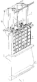
Fig.1 - view of travelling formwork along the being erected single-layer wall with lifting jacks resting upon the erected wall; -
Fig.2 - the same as inFig.1 , where oppositely facing panels form the molding cavity; -
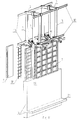
Fig.3 - view of formwork and molded "floor structure - single-layer wall" segment of building; - floor structure formwork is not shown;
-
Fig.4 - the same as inFig.3 with partial section of the molded wall, where formwork panels are brought apart, formwork rests on extendible supports of jack frames, and props of lifting jacks are extracted (their bottom sections are raised); -
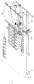
Fig.5 - the same as inFig.4 , where lifting jacks rest upon the erected wall prior lifting the formwork on the next tier/storey; -
Fig.6 - view of the jack frame post base with attached panels; -
Fig.7 - view A inFig.6 ; -
Fig.8 - section view B-B inFig.7 ; -
Fig.9 - section view C-C inFig.7 ; -
Fig.10 - section view of the top and bottom parts of the travelling formwork lifting jack; -
Fig.11 - the same as inFig.2 , where multilayer wall is erected by application of the recess-forming cages hanged on panels; -
Fig.12 - view of formwork and molded "floor structure - multi-layer wall" segment of building with recesses in the wall; floor structure formwork is not shown; -
Fig.13 - view of the vertical shuttering panel (as such not forming part of the invention) " with holes in the deck for erection of multilayer walls; -
Fig.14 - view of formwork along the erected multilayer wall with application of a panel with holes in the deck, where reinforcing rods are inserted; -
Fig.15 - view of formwork and the "floor structure - wall constructional layer" segment of building molded using panel with holes in the deck, where mesh cage is secured on reinforcing rods protruding from the constructional layer; floor structure formwork is not shown. - In the specific embodiment as defined below, travelling formwork comprises lifting jacks with props 1, where U-shaped jack frames 2 are installed on. In the base of each
post 3 of said jack frames, guides 4 are secured, whereholders 6 of thevertical shuttering panels 7 are installed with motor drive providing possibility of their motion across the being erectedvertical structures 5. Also, onposts 3 of thejack frame 2,extendible supports 8 are installed moveably. On props 1 of lifting jacks,shells 9 are installed freely with possibility of rotation and vertical motion. Lower end of eachshell 9 is located in the base of the lower (end side) arm of lifting jack.Posts 3 of adjacent jack frames 2 located on each side of the being erectedvertical structures 5 are connected with each other byrigid links 10. Travelling formwork includes alsovertical shuttering panels 7 connected rigidly with each other and secured onholders 6 of jack frames 2. Each saidpanel 7 contains bearing frame with an edge profile around the panel perimeter. Extendible supports 8 of jack frames 2 are provided with motion drive and are installed on eachpost 3 of jack frames 2 inguides 11 located at an angle (preferably 45 degrees) to the being erectedvertical structures 5. In addition, guides 11 are directed in opposite sides fromposts 3 along the being erectedvertical structures 5. It is evident thatextendible supports 8 can be located only on the one ofposts 3 of jack frames 2. In this case,extendible supports 8 on adjacent jack frames 2 will be located in the staggered order along the being erectedvertical structures 5. Such an arrangement ensures reliable resting of the whole formwork on the being erected vertical structures following extraction of props 1 of lifting jacks from them. It is also evident thatextendible supports 8 can be executed in the form of outriggers of the truck crane (supports of extendible, folding, pivotable and extendible, pivotable and folding types, etc.) and located onposts 3. Rotation drive of theshell 9 is installed on a pad located on its top end and containsgear wheel 12engaging gear ring 13 secured on outer surface in the top part of the lifting jack prop 1. When props 1 are extracted fromvertical structures 5, disengaging ofgear wheel 12 andgear ring 13 occurs. Props 1 are lifted together withshells 9. - Travelling formwork comprises also
vertical shuttering panels 7 containing bearing frame containing edge profiles around the panel perimeter. On end face of the top edge profile ofpanel 7, at least onebracket 14 with holes for fixing elements to connect withholders 6 of the U-shaped jack frames 2 can be secured. In edge profiles of the vertical shuttering panel, holes for fixing elements to connect with other panels can be performed. In the panel deck and bearing frame elements, holes for tightening devices can be performed. Panel can be sized for the whole height of tier/storey. For erection of multilayer structures,panels 15 can be used withholes 17 performed in theirdecks 16, where sleeves of elastic material are inserted. Also, for erection of multilayer structures,panels 7 can be used with removable recess-formingcages 18 hanged on them from the inner side. - Single-layer vertical structures are erected as follows.
- Lifting jacks containing props 1 enclosed in
shells 9 with U-shaped jack frames 2 provided withextendible supports 8 and installed on these props 1 are mounted on the already erectedstructures 5.Posts 3 of adjacent jack frames 2 located on each side of the being erected vertical structures are connected with each other byrigid links 10. Reinforcement cages of vertical structures are installed for the whole height of tier/storey and are secured to the protruding reinforcement of previously erected structures.Formwork panels 7 containingbrackets 14 are secured toholders 6, and allpanels 7 located in single plane are connected rigidly with each other. Width of molding cavity is adjusted by movement ofholders 6 inguides 4. Panels located in parallel on the opposite side of reinforcement cage of the being erected vertical structures are connected by means of tightening devices. Concrete is poured in molding cavities of the being erectedvertical structures 5. Reciprocating and rotational or only rotational motion is imparted toshells 9 enclosing props 1 of lifting jacks. When 30-40% design strength of erected structures is attained, U-shaped jack frames 2 are laid resting on the pouredvertical structures 5 by means ofextendible supports 8; props 1 of lifting jacks with theirenclosing shells 9 are extracted from said vertical structures, while cavities formed in these structures are filled with concrete, and the formwork panels are moved away from the molded surface. Said cavities can be filled not for the whole height (not shown in figures). In this case, sockets are left for further installation of props 1 of lifting jacks. When the required strength of concrete is attained, props 1 of lifting jacks are placed resting upon the already erectedstructures 5, U-shaped jack frames 2 are raised with formwork on the next tier/storey and the cycle of erection of vertical structures is repeated. Vertical structures can be erected simultaneously for the whole building/construction. - Multilayer vertical structures are erected as follows.
- First stages of erecting the base (constructional) layer are performed in just the same manner as described above.
- When molded structures (constructional layer) attain the stripping strength,
formwork panels 7 on one or both sides are moved away from the molded surface (an example is shown in figures, where panels are moved away only on the one side to form the second layer 22). Width of molding cavity of the new layer is adjusted and this cavity is filled with molding material. When 30-40% design strength of the base (constructional) layer is attained, U-shaped jack frames 2 are laid resting on the poured vertical structures 5 (constructional layer) by means ofextendible supports 8; props 1 of lifting jacks with theirenclosing shells 9 are extracted from said vertical structures (constructional layer), while cavities formed in these structures are filled with concrete. Theformwork panels 7 are moved away from the molded multilayer surface, props 1 of lifting jacks are placed resting on the already erected base (constructional) layer ofvertical structure 5, U-shaped jack frames 2 are raised with formwork on the next tier/storey and the cycle of erection of the multilayer vertical structures is repeated. In one of possible embodiments (Figs, 11 ,12 ), prior to fill molding cavity of the base (constructional) layer with concrete, the removable recess-formingcages 18 are hanged on the inner surface of theformwork panels 7 and removed prior molding of the last (outer) layer. Vertical structures can be erected simultaneously for the whole building/construction. Under another embodiment (Figs. 14 ,15 ), panels 15 (Fig. 13 ) are installed onposts 3 of jack frames 2. Thedeck 16 of saidpanels 15 is provided withholes 17 performed in it, where sleeves of elastic material are inserted. Following adjustment of width of molding cavity of the base (constructional) layer, reinforcingrods 19 are inserted inholes 17 with their ends located on both sides of the plane ofpanels 15. Following panels are moved away prior molding of the next layer,mesh cage 20 is secured on the inserted reinforcingrods 19. Vertical multilayer structures can be erected simultaneously for the whole building/construction. It is evident that outside the constructional layer it is possible to erect simultaneously two - facing and insulating - layers at once. In this case,panels - The "floor structure - vertical structure" segment of building/constructions is erected of monolithic reinforced concrete as follows.
- Lifting jacks containing props 1 enclosed in
shells 9 with U-shaped jack frames 2 provided withextendible supports 8 and installed on said props 1 are mounted on the already erectedstructures 5.Posts 3 of adjacent jack frames 2 located on each side of the being erected vertical structures are connected with each other byrigid links 10. Thefloor structure formwork 21 with reinforcement cages is mounted and reinforcement cages of vertical structures for the whole height of tier/storey are installed. Said reinforcement cages are secured to protruding reinforcement of previously erected vertical structures and floor structure.Formwork panels 7 containingbrackets 14 are secured toholders 6, and allpanels 7 located in single plane are connected rigidly with each other with their bottom part located at the level of the top of the floor structure formwork. Width of molding cavity is adjusted by movement ofholders 6 inguides 4.Panels 7 located in parallel on the opposite side of reinforcement cage of the being erected vertical structures are connected by means of tightening devices. Concrete of floor structure is poured and at the final stage of its setting concrete is poured in molding cavities of the being erected vertical structures. Reciprocating and rotational or only rotational motion is imparted toshells 9 enclosing props 1 of lifting jacks. When 30-40% design strength of erected structures is attained, U-shaped jack frames 2 are laid resting on the poured vertical structures 5 (constructional layer) by means ofextendible supports 8; props 1 of lifting jacks with theirenclosing shells 9 are extracted from said vertical structures, while cavities formed in these structures are filled with concrete, and the formwork panels are moved away from the molded surface. Props 1 of lifting jacks are placed resting on the already erected structures, U-shaped jack frames 2 are raised with formwork on the next tier/storey and the cycle of erection of the said building segment is repeated. Floor structure and vertical structures can be erected simultaneously for the whole building/construction. - The "floor structure -multilayer wall" segment of building/construction of monolithic reinforced concrete is erected as follows.
- First stages of works are performed in just the same manner as during erection of the "wall - floor structure" segment. When the base (constructional layer) attains the stripping strength, formwork panels on one or both sides are moved away from the molded vertical surface (an example is shown in figures, where panels are moved away only on the one side to form the second layer 22). Width of molding cavity of the new layer is adjusted and this cavity is filled with molding material. When 30-40% design strength of the base (constructional) layer of vertical structures is attained, U-shaped jack frames 2 are laid resting on the base layer by means of
extendible supports 8; props 1 of lifting jacks with theirenclosing shells 9 are extracted from said base layer, while cavities formed in vertical structures are filled with concrete. Theformwork panels 7 are moved away from the molded multilayer surface, props 1 of lifting jacks are placed resting on the erected base (constructional) layer of vertical structure, U-shaped jack frames 2 are raised with formwork on the next tier/storey and the cycle of erection of the building/construction part is repeated. Possible embodiments of the method for erecting multilayer vertical structures are disclosed above in respective section of the present patent specification. Floor structure and multilayer vertical structures can be erected simultaneously for the whole building/construction. - Utilization of inventions makes it possible to reduce consumption of materials for technological equipment and power costs for this equipment relocation. Time required for erection of buildings/constructions with multilayer vertical structures is reduced. When works are carried out simultaneously at the whole building/construction, just as it is specified in the family patent, creation of the monolithic building segment including floor slab structure of building and vertical structures of the upper tier/storey is ensured. Furthermore, rigidity and strength properties of the erected buildings/constructions are improved, which makes it possible to utilize inventions efficiently during construction activities in seismic regions.
Claims (15)
- Method for erecting vertical structural elements of building/construction of monolithic reinforced concrete including process steps of:- installing lifting jacks containing props (1) enclosed in shells (9) on already erected structures; installing U-shaped jack frames (2) equipped with posts (3) and extendible supports (8) on said posts (3); connecting the posts (3) of said jack frames (2) located adjacently on both sides of the being erected vertical structures (5) by rigid links (10);- installing reinforcement cages of the vertical structures for the whole height of a tier/storey with their connection to protruding reinforcement of the already erected structures;- installing formwork panels (7) for erection of the vertical structures (5) on the posts (3) of the jack frames (2); securing rigidly said panels (7) located in a single plane to define a molding cavity; adjusting a width of the molding cavity; and connecting said panels located in parallel on the opposite side of the reinforcement cage of the being erected vertical structures (5) by means of tightening devices;- pouring concrete into the molding cavity of the being erected vertical structures (5); imparting reciprocating and rotating or only rotating motion to the shells (9) enclosing the props (1) of the lifting jacks; resting the U-shaped jack frames (2) upon the poured vertical structures by means of the extendible supports (8) following a 30-40% design strength of the poured structures is attained; extracting the lifting jack props (1) with their enclosing shells from said poured structures which leaves a cavity in the poured structures, followed by a subsequent filling of the cavities formed in the vertical structures with concrete; and moving the formwork panels (7) away from a surface of the poured structures;- resting the props of the lifting jacks upon the already poured structures; lifting the U-shaped jack frames with the formwork panels on a next tier/storey; and repeating the cycle for erecting vertical structures.
- The method according to claim 1, wherein the vertical structures (5) are erected simultaneously for the whole building/construction.
- Method for erecting multilayer vertical structures of building/construction of monolithic reinforced concrete including process steps of:- installing lifting jacks containing props (1) enclosed in shells (9) on already erected structures; installing U-shaped jack frames (2) equipped with posts (3) and extendible supports (8) on said posts (3); connecting the posts (3) of said jack frames (2) located adjacently on both sides of the being erected multilayer vertical structures (5) by rigid links;- installing reinforcement cages of the multilayer vertical structures (5) for the whole height of a tier/storey with their connection to protruding reinforcement of the already erected structures;- installing formwork panels (7) for erection of the multilayer vertical structures (5) on the posts (3) of the jack frames (2); securing rigidly said panels (7) located in a single plane to define a molding cavity; adjusting a width of the molding cavity; and connecting said panels (7) located in parallel on the opposite side of the reinforcement cage of the being erected multilayer vertical structures (5) by means of tightening devices;- pouring concrete into the molding cavity of the being erected multilayer vertical structures (5); imparting reciprocating and rotating or only rotating motion to the shells (9) enclosing props (1) of the lifting jacks; moving the formwork panels (7) away from the poured surface on one or both sides following a stripping strength of the poured structures is attained; adjusting a width of a molding cavity of a new layer and filling said cavity with molding material;- resting the U-shaped jack frames (2) upon the poured vertical structures by means of the extendible supports (8) following a 30-40% design strength of a base constructional layer i of the poured structures is attained; extracting the props (1) of the lifting jacks with their enclosing shells (9) from said poured structures which leaves a cavity in the poured structures, followed by a subsequent filling of the cavities formed in the vertical structures with concrete;- moving the formwork panels (7) away from the poured multi-layer surface of the poured structure; resting the props (1) of the lifting jacks upon the already poured base constructional layer of the multilayer vertical structure; lifting the U-shaped jack frames (2) with the formwork panels (7) on a next tier/storey; and repeating the cycle for erecting multilayer vertical structures.
- The method according to claim 3, wherein, prior to filling the molding cavity of the base constructional layer with concrete, removable recess-forming cages (18) are hanged on an inner surface of the formwork panels (7), and, prior to molding of a last outer layer, said cages (18) are removed.
- The method according to claim 3, wherein panels (15) with holes (17) performed in their decks (16), where sleeves of elastic material are inserted, are installed on the posts (1) of the jack frames; following adjustment of a width of the molding cavity of the base constructional layer, reinforcing rods (19) are inserted in said holes (17) with the protruding ends located on both sides of the plane of the panels (15); and following moving the panels (15) away and prior to the molding of the next layer, a mesh cage (20) is secured on the inserted reinforcing rods (19).
- The method according to claims 4 or 5, wherein the vertical multilayer structures are erected simultaneously for the whole building/construction.
- A method for erecting a floor structure - vertical structure segment of a building/construction of monolithic reinforced concrete including process steps of:- installing lifting jacks containing props (1) enclosed in shells (9) on already erected vertical structures; installing U-shaped jack frames (2) equipped with posts (3) and extendible supports (8) on said posts (3); connecting the posts (3) of said jack frames (2) located adjacently on both sides of the being erected vertical structures by rigid links (10);- installing floor structure formwork (21) with reinforcement cages and installing reinforcement cages of the vertical structures for the whole height of a tier/storey with their connection to protruding reinforcement of the already erected structures and reinforcement of the floor structure;- installing formwork panels (7) for erection of the vertical structures on the posts (3) of the jack frames (2); securing rigidly said panels (7) located in a single plane to define a molding cavity; adjusting a width of the molding cavity; and connecting said panels (7) located in parallel on the opposite side of the reinforcement cage of the being erected vertical structures by means of tightening devices; locating a bottom part of the formwork panels at the level of a top part of the floor structure formwork (21);- pouring concrete of the floor structure; pouring concrete into the molding cavity of the being erected vertical structures at the final stage of setting of said floor structure concrete; imparting reciprocating and rotating or only rotating motion to shells (9) enclosing the props (1) of the lifting jacks; resting the U-shaped jack frames (2) upon the poured vertical structures by means of the extendible supports (8) following a 30-40% design strength of the poured structures is attained; extracting the props (1) of the lifting jacks with their enclosing shells (9) from said poured structures which leaves a cavity in the poured structures, followed by subsequent filling of the cavities formed in the vertical structures with concrete; and moving the formwork panels (7) away from a surface of the poured structures;- resting the props (1)of the lifting jacks upon the already poured vertical structures; lifting the U-shaped jack frames (2) with the formwork panels (7) on a next tier/storey; and repeating the cycle for erecting the vertical structures.
- The method according to claim 7, wherein the floor structure and the vertical structures of the whole building/construction are erected simultaneously.
- A method for erecting a floor structure - multilayer vertical structure segment of building/construction of monolithic reinforced concrete including process steps of:- installing lifting jacks containing props (1) enclosed in shells (9) on already erected vertical structures; installing U-shaped jack frames (2) equipped with posts (3) and extendible supports on said posts (3); connecting the posts (3) of said jack frames located adjacently on both sides of the being erected vertical structures by rigid links;- installing floor structure formwork (21) with reinforcement cages and installing reinforcement cages of the vertical structures for the whole height of a tier/storey with their connection to protruding reinforcement of the already erected structures and reinforcement of the floor structure;- installing formwork panels (7) for erection of the vertical structures on the posts (3) of the jack frames; securing rigidly said formwork panels (7) located in a single plane to define a molding cavity; adjusting a width of the molding cavity; and connecting said panels located in parallel on the opposite side of the reinforcement cage of the being erected vertical structures by means of tightening devices; locating a bottom part of the formwork panels at the level of a top part of the floor structure formwork (21);- pouring concrete of the floor structure; pouring concrete into the molding cavity of the being erected vertical structures at the final stage of setting of said floor structure concrete; imparting reciprocating and rotating or only rotating motion to the shells (9) enclosing the props (1) of the lifting jacks; moving the formwork panels (7) away from the poured surface on one or both sides following a stripping strength of the poured structures is attained; adjusting a width of a molding cavity of a new layer and filling said cavity with molding material;- resting U-shaped jack frames (2) upon the poured vertical structures by means of the extendible supports following a 30-40% design strength of a base constructional layer of the poured vertical structures is attained; extracting the lifting jack props (1) with their enclosing shells (9) from said poured vertical structures which leaves a cavity in the poured structures, followed by a subsequent filling of the cavities formed in the vertical structures with concrete;- moving the formwork panels (7) away from a multilayer surface of the poured structures; resting the props (1) of the lifting jacks upon the already poured base constructional layer of the vertical structure; lifting the U-shaped jack frames (2) with the formwork panels (7) on a next tier/storey; and repeating the cycle for erecting the building/construction segment.
- The method according to claim 9, wherein prior to filling the molding cavity of the base constructional layer with concrete, removable recess-forming cages (18) are hanged on an inner surface of the formwork panels (7), and, prior to the molding of a last outer layer, said cages (18) are removed.
- The method according to claim 9, wherein panels (15) with holes (17) performed in their decks (16), where sleeves of elastic material are inserted, are installed on the posts (3) of the jack frames; following adjustment of the width of the molding cavity of the base constructional layer, reinforcing rods (19) are inserted in said holes (17) with protruding ends located on both sides of the plane of the panels (15); and following moving the panels away and prior to the pouring of the next layer, a mesh cage (20) is secured on the inserted reinforcing rods (19).
- The method according to claims10 or 11, wherein the floor structure formwork (21) and the vertical multilayer structures of the whole building/construction are erected simultaneously.
- A travelling formwork to implement the method according to claims 1 or 3 or 7 or 9 comprising lifting jacks having props (1) with U-shaped jack frames (2) installed on them and containing posts (3); in the base of posts (3), guides (4) are secured, where holders (6) of formwork panels (7) for vertical structures (5) are installed with the possibility of travelling across erected vertical structures (5) by means of a motor drive for their motion; wherein at least one of the posts (3) of the jack frames (2) is provided with an extensible support (8) installed on it; on the props (1) of the lifting jacks, shells (9) are installed freely with the possibility of rotation and vertical motion; a lower end of each shell (9) is located on a lower end side arm of the base of the corresponding prop (1); the posts (3) of adjacent jack frames (2) being located on each side of the to be erected vertical structures (5) are connected with each other by rigid links (10); vertical formwork panels (7) are connected rigidly with each other and are secured on the holders (6); said panels (7) contain bearing frames with an edge profile around the panel perimeter.
- The travelling formwork according to claim 13, wherein the extendible supports (8) of the jack frames (2) are provided with a motion motor drive and are installed on each post (3) of said jack frames (2) in guides (11) located at an angle of preferably 45 degrees to the being erected vertical structures (5); guides (11) for the motion of the extendible supports (8) are located on the posts (3) of each U-shaped jack frame (2) are arranged in opposite directions from the posts (3) along the being erected vertical structures (5).
- The travelling formwork according to claim 13, wherein a rotation drive of a shell (9) is installed on a pad located on the top end of said shell and contains a gear wheel (12) engaging a gear ring (13) secured on an outer surface in a top part of the lifting jack prop (1).
Priority Applications (1)
| Application Number | Priority Date | Filing Date | Title |
|---|---|---|---|
| EP20192768.8A EP3779097A1 (en) | 2017-10-10 | 2018-06-08 | A shuttering panel |
Applications Claiming Priority (1)
| Application Number | Priority Date | Filing Date | Title |
|---|---|---|---|
| MDA20170087A MD4605C1 (en) | 2017-10-10 | 2017-10-10 | Processes for erecting structural components of a building/structure of cast-in-situ reinforced concrete and technological equipment for its realization |
Related Child Applications (1)
| Application Number | Title | Priority Date | Filing Date |
|---|---|---|---|
| EP20192768.8A Division EP3779097A1 (en) | 2017-10-10 | 2018-06-08 | A shuttering panel |
Publications (2)
| Publication Number | Publication Date |
|---|---|
| EP3470603A1 EP3470603A1 (en) | 2019-04-17 |
| EP3470603B1 true EP3470603B1 (en) | 2020-08-26 |
Family
ID=62597395
Family Applications (2)
| Application Number | Title | Priority Date | Filing Date |
|---|---|---|---|
| EP20192768.8A Withdrawn EP3779097A1 (en) | 2017-10-10 | 2018-06-08 | A shuttering panel |
| EP18176874.8A Active EP3470603B1 (en) | 2017-10-10 | 2018-06-08 | Method for erecting structural elements of building/construction of monolithic reinforced concrete and technological equipment to implement it |
Family Applications Before (1)
| Application Number | Title | Priority Date | Filing Date |
|---|---|---|---|
| EP20192768.8A Withdrawn EP3779097A1 (en) | 2017-10-10 | 2018-06-08 | A shuttering panel |
Country Status (2)
| Country | Link |
|---|---|
| EP (2) | EP3779097A1 (en) |
| MD (1) | MD4605C1 (en) |
Families Citing this family (3)
| Publication number | Priority date | Publication date | Assignee | Title |
|---|---|---|---|---|
| DE102019107433A1 (en) * | 2019-03-22 | 2020-09-24 | Peri Gmbh | Support structure for a formwork panel |
| CN110067380B (en) * | 2019-05-31 | 2023-11-21 | 厦门大学嘉庚学院 | Rammed earth wall mold utilizing jack sliding lifting mold and construction method thereof |
| CN115627925B (en) * | 2022-10-08 | 2025-11-25 | 上海建工集团股份有限公司 | A construction method for formwork support and ramming in rammed earth buildings |
Family Cites Families (11)
| Publication number | Priority date | Publication date | Assignee | Title |
|---|---|---|---|---|
| US4076778A (en) * | 1975-04-22 | 1978-02-28 | Alan Charles Whitting | Climbing formwork |
| RU2078884C1 (en) * | 1993-03-01 | 1997-05-10 | Нижегородский архитектурно-строительный институт | Method of monolithic building erection and movable framework for its realization |
| GB9603518D0 (en) | 1996-02-20 | 1996-04-17 | Smithkline Beecham Plc | Novel process |
| FR2803862B1 (en) * | 2000-01-18 | 2002-04-12 | Hussor S A | COMPOSITE MATERIAL FORMWORK DEVICE |
| AUPR247001A0 (en) * | 2001-01-11 | 2001-02-01 | Scallan, Patrick Joseph | On site moulding of concrete walls suitable for the building industry and other industries |
| DE102010002108A1 (en) * | 2010-02-18 | 2011-08-18 | Peri GmbH, 89264 | Anchor system of a concrete wall formwork |
| DE102010011173A1 (en) * | 2010-03-12 | 2011-09-15 | Peri Gmbh | Seal arrangement for sealing aperture in formwork board for formwork tie, has outer sleeve for being accommodated in aperture, inner sleeve accommodated in outer sleeve, and radially inward rising elastic seal formed in inner sleeve |
| MD4161C1 (en) | 2011-01-10 | 2012-10-31 | Николае Попеску | Process for erection of cast-in-situ building, complex of cast-in-situ buildings and production tooling for realization thereof |
| DE102012217689A1 (en) * | 2012-09-28 | 2014-04-03 | Harsco Infrastructure Services Gmbh | Wall formwork and wall formwork system |
| FR3035133B1 (en) * | 2015-04-16 | 2017-04-07 | Sateco Sa | FORMWORK BANK COMPRISING AN INCLINED SCALE |
| ITUB20155637A1 (en) * | 2015-11-17 | 2017-05-17 | Faresin Building S P A | PERFECT CASSERATURE STRUCTURE |
-
2017
- 2017-10-10 MD MDA20170087A patent/MD4605C1/en active IP Right Grant
-
2018
- 2018-06-08 EP EP20192768.8A patent/EP3779097A1/en not_active Withdrawn
- 2018-06-08 EP EP18176874.8A patent/EP3470603B1/en active Active
Non-Patent Citations (1)
| Title |
|---|
| None * |
Also Published As
| Publication number | Publication date |
|---|---|
| EP3470603A1 (en) | 2019-04-17 |
| EP3779097A1 (en) | 2021-02-17 |
| MD4605B1 (en) | 2018-11-30 |
| MD4605C1 (en) | 2019-06-30 |
Similar Documents
| Publication | Publication Date | Title |
|---|---|---|
| US10829927B2 (en) | Vertical slip form construction system with multi-function platform, and method of constructing a building therewith | |
| CN104520521B (en) | Concept of high-rise building elevation | |
| US10077564B1 (en) | Method for erecting a concrete structure and climbing formwork | |
| CN111663659B (en) | Staggered floor synchronous construction method | |
| EP3779097A1 (en) | A shuttering panel | |
| CN118815132B (en) | Light steel platform formwork and construction method thereof | |
| US3201502A (en) | Method of erecting concrete structures | |
| US5012627A (en) | Construction process for multiple-story concrete building | |
| CN115110765A (en) | Construction method and device for shear wall at deformation joint | |
| WO2017054723A1 (en) | Concave building template set construction method | |
| CN118208066B (en) | Construction method for layer-adding transformation of interior of existing cylindrical structure | |
| KR101140884B1 (en) | Gangform device constructed for wall and constructing method this using | |
| KR102425501B1 (en) | Silo construction method using precast and slip foam | |
| KR102430362B1 (en) | Structure for precast construction of inner cone of silo and precast construction method of inner cone of silo using the same | |
| US3552080A (en) | Method for erecting multistory buildings | |
| CN106555479B (en) | Hoisting equipment for concave-shaped floor forming device | |
| RU2685586C1 (en) | Method for erection of constructive elements of building/construction from monolithic concrete and technological equipment for implementation thereof (invention group, options) | |
| CN205153561U (en) | Hoisting equipment of concave floor forming device | |
| US4029286A (en) | Apparatus for the construction of ceiling in multi-story concrete buildings | |
| RU2716319C1 (en) | Method of erection of buildings and structures | |
| KR101234201B1 (en) | Method for constructing tower silo | |
| AU597836B2 (en) | Wall casting system | |
| EP1233123A2 (en) | A bricklaying method and an arrangement for the implementation thereof | |
| CN116591461B (en) | A monolithic core column lifting formwork system and construction method | |
| RU76040U1 (en) | VOLUME REINFORCED FRAME FOR ESTABLISHING MONOLITHIC REINFORCED CONCRETE COVERING |
Legal Events
| Date | Code | Title | Description |
|---|---|---|---|
| PUAI | Public reference made under article 153(3) epc to a published international application that has entered the european phase |
Free format text: ORIGINAL CODE: 0009012 |
|
| STAA | Information on the status of an ep patent application or granted ep patent |
Free format text: STATUS: REQUEST FOR EXAMINATION WAS MADE |
|
| 17P | Request for examination filed |
Effective date: 20180608 |
|
| AK | Designated contracting states |
Kind code of ref document: A1 Designated state(s): AL AT BE BG CH CY CZ DE DK EE ES FI FR GB GR HR HU IE IS IT LI LT LU LV MC MK MT NL NO PL PT RO RS SE SI SK SM TR |
|
| AX | Request for extension of the european patent |
Extension state: BA ME |
|
| GRAP | Despatch of communication of intention to grant a patent |
Free format text: ORIGINAL CODE: EPIDOSNIGR1 |
|
| STAA | Information on the status of an ep patent application or granted ep patent |
Free format text: STATUS: GRANT OF PATENT IS INTENDED |
|
| INTG | Intention to grant announced |
Effective date: 20200219 |
|
| GRAS | Grant fee paid |
Free format text: ORIGINAL CODE: EPIDOSNIGR3 |
|
| GRAJ | Information related to disapproval of communication of intention to grant by the applicant or resumption of examination proceedings by the epo deleted |
Free format text: ORIGINAL CODE: EPIDOSDIGR1 |
|
| GRAL | Information related to payment of fee for publishing/printing deleted |
Free format text: ORIGINAL CODE: EPIDOSDIGR3 |
|
| STAA | Information on the status of an ep patent application or granted ep patent |
Free format text: STATUS: REQUEST FOR EXAMINATION WAS MADE |
|
| GRAR | Information related to intention to grant a patent recorded |
Free format text: ORIGINAL CODE: EPIDOSNIGR71 |
|
| STAA | Information on the status of an ep patent application or granted ep patent |
Free format text: STATUS: GRANT OF PATENT IS INTENDED |
|
| GRAA | (expected) grant |
Free format text: ORIGINAL CODE: 0009210 |
|
| STAA | Information on the status of an ep patent application or granted ep patent |
Free format text: STATUS: THE PATENT HAS BEEN GRANTED |
|
| INTC | Intention to grant announced (deleted) | ||
| INTG | Intention to grant announced |
Effective date: 20200715 |
|
| AK | Designated contracting states |
Kind code of ref document: B1 Designated state(s): AL AT BE BG CH CY CZ DE DK EE ES FI FR GB GR HR HU IE IS IT LI LT LU LV MC MK MT NL NO PL PT RO RS SE SI SK SM TR |
|
| REG | Reference to a national code |
Ref country code: GB Ref legal event code: FG4D |
|
| REG | Reference to a national code |
Ref country code: CH Ref legal event code: EP |
|
| REG | Reference to a national code |
Ref country code: AT Ref legal event code: REF Ref document number: 1306510 Country of ref document: AT Kind code of ref document: T Effective date: 20200915 |
|
| REG | Reference to a national code |
Ref country code: IE Ref legal event code: FG4D |
|
| REG | Reference to a national code |
Ref country code: DE Ref legal event code: R096 Ref document number: 602018007214 Country of ref document: DE |
|
| REG | Reference to a national code |
Ref country code: RO Ref legal event code: EPE |
|
| REG | Reference to a national code |
Ref country code: LT Ref legal event code: MG4D |
|
| PG25 | Lapsed in a contracting state [announced via postgrant information from national office to epo] |
Ref country code: FI Free format text: LAPSE BECAUSE OF FAILURE TO SUBMIT A TRANSLATION OF THE DESCRIPTION OR TO PAY THE FEE WITHIN THE PRESCRIBED TIME-LIMIT Effective date: 20200826 Ref country code: LT Free format text: LAPSE BECAUSE OF FAILURE TO SUBMIT A TRANSLATION OF THE DESCRIPTION OR TO PAY THE FEE WITHIN THE PRESCRIBED TIME-LIMIT Effective date: 20200826 Ref country code: BG Free format text: LAPSE BECAUSE OF FAILURE TO SUBMIT A TRANSLATION OF THE DESCRIPTION OR TO PAY THE FEE WITHIN THE PRESCRIBED TIME-LIMIT Effective date: 20201126 Ref country code: NO Free format text: LAPSE BECAUSE OF FAILURE TO SUBMIT A TRANSLATION OF THE DESCRIPTION OR TO PAY THE FEE WITHIN THE PRESCRIBED TIME-LIMIT Effective date: 20201126 Ref country code: GR Free format text: LAPSE BECAUSE OF FAILURE TO SUBMIT A TRANSLATION OF THE DESCRIPTION OR TO PAY THE FEE WITHIN THE PRESCRIBED TIME-LIMIT Effective date: 20201127 Ref country code: PT Free format text: LAPSE BECAUSE OF FAILURE TO SUBMIT A TRANSLATION OF THE DESCRIPTION OR TO PAY THE FEE WITHIN THE PRESCRIBED TIME-LIMIT Effective date: 20201228 Ref country code: HR Free format text: LAPSE BECAUSE OF FAILURE TO SUBMIT A TRANSLATION OF THE DESCRIPTION OR TO PAY THE FEE WITHIN THE PRESCRIBED TIME-LIMIT Effective date: 20200826 Ref country code: SE Free format text: LAPSE BECAUSE OF FAILURE TO SUBMIT A TRANSLATION OF THE DESCRIPTION OR TO PAY THE FEE WITHIN THE PRESCRIBED TIME-LIMIT Effective date: 20200826 |
|
| REG | Reference to a national code |
Ref country code: NL Ref legal event code: MP Effective date: 20200826 |
|
| REG | Reference to a national code |
Ref country code: AT Ref legal event code: MK05 Ref document number: 1306510 Country of ref document: AT Kind code of ref document: T Effective date: 20200826 |
|
| PG25 | Lapsed in a contracting state [announced via postgrant information from national office to epo] |
Ref country code: PL Free format text: LAPSE BECAUSE OF FAILURE TO SUBMIT A TRANSLATION OF THE DESCRIPTION OR TO PAY THE FEE WITHIN THE PRESCRIBED TIME-LIMIT Effective date: 20200826 Ref country code: RS Free format text: LAPSE BECAUSE OF FAILURE TO SUBMIT A TRANSLATION OF THE DESCRIPTION OR TO PAY THE FEE WITHIN THE PRESCRIBED TIME-LIMIT Effective date: 20200826 Ref country code: LV Free format text: LAPSE BECAUSE OF FAILURE TO SUBMIT A TRANSLATION OF THE DESCRIPTION OR TO PAY THE FEE WITHIN THE PRESCRIBED TIME-LIMIT Effective date: 20200826 Ref country code: NL Free format text: LAPSE BECAUSE OF FAILURE TO SUBMIT A TRANSLATION OF THE DESCRIPTION OR TO PAY THE FEE WITHIN THE PRESCRIBED TIME-LIMIT Effective date: 20200826 Ref country code: IS Free format text: LAPSE BECAUSE OF FAILURE TO SUBMIT A TRANSLATION OF THE DESCRIPTION OR TO PAY THE FEE WITHIN THE PRESCRIBED TIME-LIMIT Effective date: 20201226 |
|
| PG25 | Lapsed in a contracting state [announced via postgrant information from national office to epo] |
Ref country code: SM Free format text: LAPSE BECAUSE OF FAILURE TO SUBMIT A TRANSLATION OF THE DESCRIPTION OR TO PAY THE FEE WITHIN THE PRESCRIBED TIME-LIMIT Effective date: 20200826 Ref country code: CZ Free format text: LAPSE BECAUSE OF FAILURE TO SUBMIT A TRANSLATION OF THE DESCRIPTION OR TO PAY THE FEE WITHIN THE PRESCRIBED TIME-LIMIT Effective date: 20200826 Ref country code: DK Free format text: LAPSE BECAUSE OF FAILURE TO SUBMIT A TRANSLATION OF THE DESCRIPTION OR TO PAY THE FEE WITHIN THE PRESCRIBED TIME-LIMIT Effective date: 20200826 Ref country code: EE Free format text: LAPSE BECAUSE OF FAILURE TO SUBMIT A TRANSLATION OF THE DESCRIPTION OR TO PAY THE FEE WITHIN THE PRESCRIBED TIME-LIMIT Effective date: 20200826 |
|
| REG | Reference to a national code |
Ref country code: DE Ref legal event code: R097 Ref document number: 602018007214 Country of ref document: DE |
|
| PG25 | Lapsed in a contracting state [announced via postgrant information from national office to epo] |
Ref country code: AT Free format text: LAPSE BECAUSE OF FAILURE TO SUBMIT A TRANSLATION OF THE DESCRIPTION OR TO PAY THE FEE WITHIN THE PRESCRIBED TIME-LIMIT Effective date: 20200826 Ref country code: AL Free format text: LAPSE BECAUSE OF FAILURE TO SUBMIT A TRANSLATION OF THE DESCRIPTION OR TO PAY THE FEE WITHIN THE PRESCRIBED TIME-LIMIT Effective date: 20200826 Ref country code: ES Free format text: LAPSE BECAUSE OF FAILURE TO SUBMIT A TRANSLATION OF THE DESCRIPTION OR TO PAY THE FEE WITHIN THE PRESCRIBED TIME-LIMIT Effective date: 20200826 |
|
| PG25 | Lapsed in a contracting state [announced via postgrant information from national office to epo] |
Ref country code: SK Free format text: LAPSE BECAUSE OF FAILURE TO SUBMIT A TRANSLATION OF THE DESCRIPTION OR TO PAY THE FEE WITHIN THE PRESCRIBED TIME-LIMIT Effective date: 20200826 |
|
| PLBE | No opposition filed within time limit |
Free format text: ORIGINAL CODE: 0009261 |
|
| STAA | Information on the status of an ep patent application or granted ep patent |
Free format text: STATUS: NO OPPOSITION FILED WITHIN TIME LIMIT |
|
| PG25 | Lapsed in a contracting state [announced via postgrant information from national office to epo] |
Ref country code: IT Free format text: LAPSE BECAUSE OF FAILURE TO SUBMIT A TRANSLATION OF THE DESCRIPTION OR TO PAY THE FEE WITHIN THE PRESCRIBED TIME-LIMIT Effective date: 20200826 |
|
| 26N | No opposition filed |
Effective date: 20210527 |
|
| PG25 | Lapsed in a contracting state [announced via postgrant information from national office to epo] |
Ref country code: SI Free format text: LAPSE BECAUSE OF FAILURE TO SUBMIT A TRANSLATION OF THE DESCRIPTION OR TO PAY THE FEE WITHIN THE PRESCRIBED TIME-LIMIT Effective date: 20200826 |
|
| PG25 | Lapsed in a contracting state [announced via postgrant information from national office to epo] |
Ref country code: MC Free format text: LAPSE BECAUSE OF FAILURE TO SUBMIT A TRANSLATION OF THE DESCRIPTION OR TO PAY THE FEE WITHIN THE PRESCRIBED TIME-LIMIT Effective date: 20200826 |
|
| REG | Reference to a national code |
Ref country code: CH Ref legal event code: PL |
|
| REG | Reference to a national code |
Ref country code: BE Ref legal event code: MM Effective date: 20210630 |
|
| PG25 | Lapsed in a contracting state [announced via postgrant information from national office to epo] |
Ref country code: LU Free format text: LAPSE BECAUSE OF NON-PAYMENT OF DUE FEES Effective date: 20210608 |
|
| PG25 | Lapsed in a contracting state [announced via postgrant information from national office to epo] |
Ref country code: LI Free format text: LAPSE BECAUSE OF NON-PAYMENT OF DUE FEES Effective date: 20210630 Ref country code: IE Free format text: LAPSE BECAUSE OF NON-PAYMENT OF DUE FEES Effective date: 20210608 Ref country code: CH Free format text: LAPSE BECAUSE OF NON-PAYMENT OF DUE FEES Effective date: 20210630 |
|
| PG25 | Lapsed in a contracting state [announced via postgrant information from national office to epo] |
Ref country code: BE Free format text: LAPSE BECAUSE OF NON-PAYMENT OF DUE FEES Effective date: 20210630 |
|
| PG25 | Lapsed in a contracting state [announced via postgrant information from national office to epo] |
Ref country code: CY Free format text: LAPSE BECAUSE OF FAILURE TO SUBMIT A TRANSLATION OF THE DESCRIPTION OR TO PAY THE FEE WITHIN THE PRESCRIBED TIME-LIMIT Effective date: 20200826 |
|
| PG25 | Lapsed in a contracting state [announced via postgrant information from national office to epo] |
Ref country code: HU Free format text: LAPSE BECAUSE OF FAILURE TO SUBMIT A TRANSLATION OF THE DESCRIPTION OR TO PAY THE FEE WITHIN THE PRESCRIBED TIME-LIMIT; INVALID AB INITIO Effective date: 20180608 |
|
| PGFP | Annual fee paid to national office [announced via postgrant information from national office to epo] |
Ref country code: RO Payment date: 20230606 Year of fee payment: 6 |
|
| PG25 | Lapsed in a contracting state [announced via postgrant information from national office to epo] |
Ref country code: MK Free format text: LAPSE BECAUSE OF FAILURE TO SUBMIT A TRANSLATION OF THE DESCRIPTION OR TO PAY THE FEE WITHIN THE PRESCRIBED TIME-LIMIT Effective date: 20200826 |
|
| REG | Reference to a national code |
Ref country code: GB Ref legal event code: 732E Free format text: REGISTERED BETWEEN 20240808 AND 20240814 |
|
| REG | Reference to a national code |
Ref country code: DE Ref legal event code: R082 Ref document number: 602018007214 Country of ref document: DE Representative=s name: PATENTANWALTSKANZLEI LIERMANN-CASTELL, DE Ref country code: DE Ref legal event code: R081 Ref document number: 602018007214 Country of ref document: DE Owner name: POPESCU, PAVEL, TRUMPINGTON, GB Free format text: FORMER OWNERS: CORETCHI, ANA, CHISINAU, MD; POPESCU, NICOLAE, CHISINAU, MD; POPESCU, PAVEL, CHISINAU, MD |
|
| PG25 | Lapsed in a contracting state [announced via postgrant information from national office to epo] |
Ref country code: MT Free format text: LAPSE BECAUSE OF FAILURE TO SUBMIT A TRANSLATION OF THE DESCRIPTION OR TO PAY THE FEE WITHIN THE PRESCRIBED TIME-LIMIT Effective date: 20200826 |
|
| PG25 | Lapsed in a contracting state [announced via postgrant information from national office to epo] |
Ref country code: RO Free format text: LAPSE BECAUSE OF NON-PAYMENT OF DUE FEES Effective date: 20240608 |
|
| PG25 | Lapsed in a contracting state [announced via postgrant information from national office to epo] |
Ref country code: RO Free format text: LAPSE BECAUSE OF NON-PAYMENT OF DUE FEES Effective date: 20240608 |
|
| PGFP | Annual fee paid to national office [announced via postgrant information from national office to epo] |
Ref country code: DE Payment date: 20250626 Year of fee payment: 8 |
|
| PGFP | Annual fee paid to national office [announced via postgrant information from national office to epo] |
Ref country code: GB Payment date: 20250626 Year of fee payment: 8 |
|
| PGFP | Annual fee paid to national office [announced via postgrant information from national office to epo] |
Ref country code: FR Payment date: 20250623 Year of fee payment: 8 |
|
| PGFP | Annual fee paid to national office [announced via postgrant information from national office to epo] |
Ref country code: TR Payment date: 20250610 Year of fee payment: 8 |