EP3470583B1 - Tractor - Google Patents
Tractor Download PDFInfo
- Publication number
- EP3470583B1 EP3470583B1 EP18194563.5A EP18194563A EP3470583B1 EP 3470583 B1 EP3470583 B1 EP 3470583B1 EP 18194563 A EP18194563 A EP 18194563A EP 3470583 B1 EP3470583 B1 EP 3470583B1
- Authority
- EP
- European Patent Office
- Prior art keywords
- control unit
- support member
- frame
- disposed
- supported
- Prior art date
- Legal status (The legal status is an assumption and is not a legal conclusion. Google has not performed a legal analysis and makes no representation as to the accuracy of the status listed.)
- Active
Links
- 238000009413 insulation Methods 0.000 claims description 7
- 230000000630 rising effect Effects 0.000 claims description 7
- 230000005540 biological transmission Effects 0.000 description 12
- OIWCYIUQAVBPGV-DAQGAKHBSA-N {1-O-hexadecanoyl-2-O-[(Z)-octadec-9-enoyl]-sn-glycero-3-phospho}serine Chemical compound CCCCCCCCCCCCCCCC(=O)OC[C@H](COP(O)(=O)OC[C@H](N)C(O)=O)OC(=O)CCCCCCC\C=C/CCCCCCCC OIWCYIUQAVBPGV-DAQGAKHBSA-N 0.000 description 12
- 238000012423 maintenance Methods 0.000 description 7
- 238000000638 solvent extraction Methods 0.000 description 5
- 230000001419 dependent effect Effects 0.000 description 1
Images


Classifications
-
- E—FIXED CONSTRUCTIONS
- E02—HYDRAULIC ENGINEERING; FOUNDATIONS; SOIL SHIFTING
- E02F—DREDGING; SOIL-SHIFTING
- E02F9/00—Component parts of dredgers or soil-shifting machines, not restricted to one of the kinds covered by groups E02F3/00 - E02F7/00
- E02F9/08—Superstructures; Supports for superstructures
- E02F9/0833—Improving access, e.g. for maintenance, steps for improving driver's access, handrails
-
- B—PERFORMING OPERATIONS; TRANSPORTING
- B60—VEHICLES IN GENERAL
- B60N—SEATS SPECIALLY ADAPTED FOR VEHICLES; VEHICLE PASSENGER ACCOMMODATION NOT OTHERWISE PROVIDED FOR
- B60N2/00—Seats specially adapted for vehicles; Arrangement or mounting of seats in vehicles
- B60N2/24—Seats specially adapted for vehicles; Arrangement or mounting of seats in vehicles for particular purposes or particular vehicles
- B60N2/38—Seats specially adapted for vehicles; Arrangement or mounting of seats in vehicles for particular purposes or particular vehicles specially constructed for use on tractors or like off-road vehicles
-
- B—PERFORMING OPERATIONS; TRANSPORTING
- B60—VEHICLES IN GENERAL
- B60R—VEHICLES, VEHICLE FITTINGS, OR VEHICLE PARTS, NOT OTHERWISE PROVIDED FOR
- B60R16/00—Electric or fluid circuits specially adapted for vehicles and not otherwise provided for; Arrangement of elements of electric or fluid circuits specially adapted for vehicles and not otherwise provided for
- B60R16/02—Electric or fluid circuits specially adapted for vehicles and not otherwise provided for; Arrangement of elements of electric or fluid circuits specially adapted for vehicles and not otherwise provided for electric constitutive elements
- B60R16/023—Electric or fluid circuits specially adapted for vehicles and not otherwise provided for; Arrangement of elements of electric or fluid circuits specially adapted for vehicles and not otherwise provided for electric constitutive elements for transmission of signals between vehicle parts or subsystems
- B60R16/0231—Circuits relating to the driving or the functioning of the vehicle
- B60R16/0232—Circuits relating to the driving or the functioning of the vehicle for measuring vehicle parameters and indicating critical, abnormal or dangerous conditions
- B60R16/0234—Circuits relating to the driving or the functioning of the vehicle for measuring vehicle parameters and indicating critical, abnormal or dangerous conditions related to maintenance or repairing of vehicles
-
- B—PERFORMING OPERATIONS; TRANSPORTING
- B60—VEHICLES IN GENERAL
- B60R—VEHICLES, VEHICLE FITTINGS, OR VEHICLE PARTS, NOT OTHERWISE PROVIDED FOR
- B60R16/00—Electric or fluid circuits specially adapted for vehicles and not otherwise provided for; Arrangement of elements of electric or fluid circuits specially adapted for vehicles and not otherwise provided for
- B60R16/02—Electric or fluid circuits specially adapted for vehicles and not otherwise provided for; Arrangement of elements of electric or fluid circuits specially adapted for vehicles and not otherwise provided for electric constitutive elements
- B60R16/023—Electric or fluid circuits specially adapted for vehicles and not otherwise provided for; Arrangement of elements of electric or fluid circuits specially adapted for vehicles and not otherwise provided for electric constitutive elements for transmission of signals between vehicle parts or subsystems
- B60R16/0239—Electronic boxes
-
- B—PERFORMING OPERATIONS; TRANSPORTING
- B60—VEHICLES IN GENERAL
- B60R—VEHICLES, VEHICLE FITTINGS, OR VEHICLE PARTS, NOT OTHERWISE PROVIDED FOR
- B60R21/00—Arrangements or fittings on vehicles for protecting or preventing injuries to occupants or pedestrians in case of accidents or other traffic risks
- B60R21/02—Occupant safety arrangements or fittings, e.g. crash pads
- B60R21/13—Roll-over protection
- B60R21/131—Protective devices for drivers in case of overturning of tractors
-
- E—FIXED CONSTRUCTIONS
- E02—HYDRAULIC ENGINEERING; FOUNDATIONS; SOIL SHIFTING
- E02F—DREDGING; SOIL-SHIFTING
- E02F9/00—Component parts of dredgers or soil-shifting machines, not restricted to one of the kinds covered by groups E02F3/00 - E02F7/00
- E02F9/08—Superstructures; Supports for superstructures
- E02F9/0858—Arrangement of component parts installed on superstructures not otherwise provided for, e.g. electric components, fenders, air-conditioning units
-
- E—FIXED CONSTRUCTIONS
- E02—HYDRAULIC ENGINEERING; FOUNDATIONS; SOIL SHIFTING
- E02F—DREDGING; SOIL-SHIFTING
- E02F9/00—Component parts of dredgers or soil-shifting machines, not restricted to one of the kinds covered by groups E02F3/00 - E02F7/00
- E02F9/16—Cabins, platforms, or the like, for drivers
-
- B—PERFORMING OPERATIONS; TRANSPORTING
- B62—LAND VEHICLES FOR TRAVELLING OTHERWISE THAN ON RAILS
- B62D—MOTOR VEHICLES; TRAILERS
- B62D49/00—Tractors
Definitions
- the present invention relates to an arrangement of a control unit on a tractor.
- JP 2014 175160 A discloses a seat of a tractor which can be raised up to a working state and laid down to a laid state laid toward the front of a machine frame.
- a rotary apparatus supported on the rear part of a travelling machine frame is controlled so as to ascend and descend by a hydraulic cylinder via a control unit.
- Patent Document 1 Japanese Unexamined Patent Application No. 2014-205367 [Summary of the Invention]
- An object of the present invention is to improve maintenance of the control unit when a control unit is disposed on the tractor.
- the support member disposed in a rear portion of a machine frame, for supporting a lower portion of a driver's seat in the tractor is positioned at a rear portion of the driving unit.
- the lower side of the rear portion of the rear side of the driver's seat in the support member is a region that corresponds to an outside of the driving unit, and is open to the rear side.
- Left and right rear-wheel fenders exist at left and right lateral sides of this region.
- a control unit in a region opened to the rear side avoiding a lower side of the driver's seat where multiple devices and members exist, by support the control unit at the lower side at a rear portion of the support member, thereby making it possible to conduct maintenance on the control unit from the rear side without difficulty.
- the lower side of the rear portion of the support member is a region that corresponds to the outside of the driving unit. Even if the cabin that covers the driver's seat is disposed, the control unit is arranged at the outside of the cabin.
- the present invention it is possible to improve the maintenance of the control unit in light of the point that it is possible to implement maintenance work on the control unit from the rear side without difficulty, and the point that even if the cabin that covers the driver's seat is disposed, the control unit is arranged at the outside of the cabin.
- control unit is supported between the left and right fenders and at the lower side of the rear portion of the support member so the upper, left and right sides of the control unit are surrounded and protected. This is advantageous in the aspect of preventing damage to the control unit.
- a vertical face portion along left and right directions, and a lateral face portion along left and right directions are disposed in the rear portion of the support member, and has a shape rising rearwards when seen in side view; and the control unit is supported at the lower side of the lateral face portion, at a rear side of the vertical face portion.
- the present invention it is possible to attain a state where the control unit faces the rear side when the control unit is supported at the lower side of the rear portion of the support member, by making the rear portion of the support member have a rising shape, so it is possible to conduct maintenance on the control unit from the rear side without difficulty.
- the rear portion of the support member when the rear portion of the support member has a rising shape, dispose the rear portion of the support member, a vertical face portion along left and right directions, and a lateral face portion along left and right directions. With this, it is possible easily to attain a state where the control unit faces the rear side by mounting a boxshaped control unit, for example, to the vertical face portion and the horizontal face portion of the rear portion of the support member.
- a lifter arm that freely swings up and down is disposed at the lower side of the rear portion of the support member, and the control unit is supported between the left or right fender and the lifter arm when seen in the plan view.
- the control unit is supported between the left or right fender and the lifter arm thereby making it possible to arrange the control unit while avoiding the up and down rocking trajectory of the lifter arm without difficulty.
- control unit is supported by the machine body via a vibration-insulation member.
- the support member is supported by the machine body via the vibration-insulation member. It is difficult for vibrations to be transmitted to the control unit so this is advantageous in the aspect of preventing damage to the control unit.
- a cover that covers the rear side of the control unit is disposed.
- the upper, left, and right sides of the control unit are protected by the left and right fenders and the rear portion of the support member, and the rear side of the control unit is protected by the cover, so this is advantageous in the aspect of preventing damage to the control unit.
- a connector is disposed facing downward at a lower portion of the control unit, and a portion opposing the connector in the cover is open.
- the portion opposing the connector in the control unit is open in the cover that covers the rear side of the control unit, so it is possible to arrange a harness that is connected to the control unit connector without difficulty.
- a base of ROPS frame is connected to the rear portion of the machine body, the ROPS frame extending to an upper side; and the base is arranged at the rear side of the control unit.
- the base of the POPS frame is connected to the rear portion of the machine body, and the POPS frame extends to anupper side.
- the base of the POPS frame is arranged at the rear side of the control unit, and the rear side of the control unit is protected by the base of the POPS frame, so this is advantageous in the aspect of preventing damage to the control unit.
- a frame along the left and right directions is connected across the left and right base portions, to be positioned at the upper side of the control unit when viewed from the back side.
- the frame connected across the left and right base portions of the POPS frame is arranged at the upper side of the rear side of the control unit; the uppers side of the rear side of the control unit is protected by the frame, so this is advantageous in the aspect of preventing damage to the control unit.
- a tool box is supported on the frame to be positioned at an upper side of the frame.
- the frame can be dually used for the tool box support member by supporting the tool box on the frame connected across the left and right base portions of the POPS frame. This is advantageous in the aspect of simplifying the structure.
- disposed are left and right front wheels 1, and left and right rear wheels 2, and a machine body 3 supported by the front wheels 1 and the rear wheels 2, and the driving unit 4 is supported by the machine body 3.
- the main body 3 is equipped with an engine 5 at the front side, and transmission case 6 at the rear side. The engine 5 and transmission case 6 are linked.
- the ROPS frame is linked to the rear portion of the transmission case 6 and extends to the upward side.
- the ROPS frame 7 is arranged at a rear side of the driving unit 4.
- the left and lifter arms 8, and left and right lift cylinders 31 that rockingly drive the lifter arms are disposed behind the transmission case 6.
- Each type of work device (not shown in the drawings) can be linked to the rear of the transmission case 6.
- the work devices can be raised and lowered by the lifter arms 8.
- the driving unit 4 is equipped with a driver's seat 9, a steering wheel 10 for steering the front wheels 1, and a floor 11 arranged below the driving unit 4.
- the driving unit 4 is arranged behind the engine 5, and arranged above the transmission case 6.
- Fenders 12 are disposed at the left and right rear wheels 2.
- the left and right fenders 12 are arranged at left and right horizontal sides of the driver's seat 9.
- a partitioning wall 13 is arranged between the driving unit 4, and the engine 5.
- the steering wheel 10 is arranged behind the partitioning wall 13.
- the space between the partitioning wall 13 and the right fender 12 is an egress-ingress area 14 at a right side of the driving unit 4.
- the space between the partitioning wall 13 and the left fender 12 is an egress-ingress area 14 at a left side of the driving unit 4.
- the driver egresses and ingresses the driving unit 4 mainly through the egress-ingress area 14 on the left side.
- a railing frame 15 is arranged in front of the left-side egress-ingress area 14 in the egress-ingress area 14. Handles 16 are linked above the left and right fenders 12. Step 17 is linked to the left side of the floor 11, and step 17 is arranged below the egress-ingress area 14.
- the driver will grab the railing frame 15 with their left hand, and grab the handle 16 on the left and right fenders 12, at the left side egress-ingress area 14, place their foot on the step 17 and egress-ingress to the driving unit 4.
- a support member 20 is disposed behind the machine body 3, and a lower portion of the driver's seat 9 (a seat) is supported by the support member 20.
- a lever guide 19 is disposed at a left, top side of the support member 20 and between the driver's seat 9 and left fender 12.
- a parking brake lever 18, operation handle 22 and a gear shifting lever 23 are arranged on the lever guide 19.
- the parking brake lever 18 can implement operations to release and engage the brake of the parking brake (not shown in the drawings) disposed in the transmission case 6.
- the operation lever 22 can block the transmission of motive power to the front wheels 1 and set to a two-wheel drive state in which only the rear wheels 2 are driven, or to a four-wheel drive state in which the front wheels 1 and the rear wheels 2 are driven.
- a gear shifter (not shown in the drawings) for travel is disposed in the transmission case 6.
- the gear shifter for travel can be operated for 3 gears for forward and 1 gear for reverse.
- the gear shifting lever 23 can operate the gear shifter for travel.
- the support member 20 is equipped with a front portion 25 and a rear portion 26.
- the front portion 25 and the rear portion 26 of the support member 20 span the left and right fenders 12.
- the left and right left and right rear-wheel fenders 12 disposed at the left and right lateral side portions for the front portion 25 and the rear portion 26 of the support member 20.
- a bracket 21 is linked to the left and right portions behind the transmission case 6.
- the front portion 25 of the support member 20 is arranged facing laterally; the support member 20 is supported by the machine body 3 via a vibration-insulation member 24 and the bracket 21
- a bottom (a seat) of the driver's seat 9 is supported by the front portion 25 of the support member 20; the rear portion 26 of the support member 20 is a portion of the rear side of the driver's seat 9.
- the rear portion 26 of the support member 20 is equipped with a vertical face portion 26a along left and right directions connected to a rear-end portion of the front portion 25 of the support member 20, and a lateral face portion 26b along left and right directions connected to a top portion of the vertical face portion 26a. With this, the rear portion 26 of the support member 20 has a step-shaped rear rising shape when seen in side view.
- control unit 27 is supported between the left and right fenders 12 and at the lower side of the portion of the rear portion 26 of the support member 20, and arranged at a rear side of the lever guide 19.
- a bracket 32 is linked to a rear face of the left portion of the vertical face portion 26a, and the control unit 27 is mounted to the bracket 32.
- the control unit 27 is arranged at a lower side of the lateral face portion 26b at the rear portion 26 of the support member 20.
- the bracket 32 it is acceptable to link the bracket 32 to a lower face of the left portion of the lateral face portion 26b, in the rear portion 26 of the support member 20, and to mouth the control unit 27 to the bracket 32.
- the control unit 27 is arranged at a rear side of the vertical face portion 26a at the rear portion 26 of the support member 20.
- Left and right lifter arms 8 are arranged at a lower side of the rear portion 26 of the support member 20.
- the control unit 27 is supported to touch the left fender 12. With this, the control unit 27 is in a state supported between the left fender 12 and the left lifter arm 8 when seen in the plan view. In Fig. 4 , when the lifter arm 8 rises up to its upper limit position, the control unit 27 is supported between the fender 12 and the left lifter arm 8 when seen from the back side.
- control unit 27 it is acceptable to support the control unit 27 to touch the right fender, and so that the control unit 27 is supported between the right fender 12 and the right lifter arm 8 when seen in the plan view.
- a cover 28 is mounted to the bracket 32 by a bolt 33 at the ear portion 26 of the support member 20. A rear side of the control unit 27 is covered by the cover 28. The cover 28 can be removed by removing the bolt 33.
- a connector 27a of the control unit 27 is disposed facing downward at a lower portion of the control unit 27.
- a portion of a lower side opposing the connector 27a of the control unit 27 is open, in the cover 28.
- a connector 27a of the control unit 27 is arranged in the portion open at a lower side of the cover 28.
- the ROPS frame is equipped with left and right base portions 7a, and a loop-shaped top portion 7b.
- Left and right rear wheel axle cases 29 are linked to the rear of the transmission case 6.
- the rear wheels 2 are supported by the rear wheel axle case 29.
- a bracket 30 is linked to the rear wheel axle case 29.
- the base portion 7a of the POPS frame is linked to the bracket 30, and the ROPS frame 7 extends to a top side.
- the base portion 7a of the POPS frame 7 is arranged along up and down directions at the rear side of the control unit 27 and cover 28.
- a frame 35 is linked across a top portion of the left and right base portions 7a of the POPS frame 7.
- a lateral-facing frame 36 is linked to an upper portion of the frame 35, and a tool box 37 is linked to left and right upward facing brackets 36a of the frame 36.
- a support plate 38 for mounting a license plate (not shown in the drawings) is connected to a left portion of the frame 36.
- a frame 35 connected across a top portion of the left and right base portions 7a of the POPS frame 7 is arranged at an upper side at a rear side of the control unit 27 and cover 28.
- the frames 35, and 36, the tool box 37, and the support plate 38 are arranged further at the upper side than the horizontal face portion 26b at the rear portion 26 of the support member 20 when seen from the back side. With this, a worker standing at the rear side of the transmission case 6 cannot work using the frames 35 and 36, the tool box 37, and support plate 38 even if they extend their hand to the driving unit 4.
- the ROPS frame 7 is constituted to be low, so that the upper portion 7b of the ROPS frame 7 is arranged at a position that is substantially the same height as the upper end portion of the backrest of the driver's seat 9.
- the frame 35 shown in Figs. 3 and 4 is removed, and the frame 36 linked with the tool box 37 is connected across the left and right base portions 7a of the ROPS frame 7.
- a high-back ROPS frame 39 is disposed at a front portion of the driving unit 4.
- the ROPS frame 39 extends to an upper side along the left and right sides of the partitioning wall 13.
- the cabin 40 is disposed that covers the driving unit 4.
- the support member 20 is connected to the cabin 40.
- a bracket 41 is connected to left and right rear wheel axle cases 29.
- Left and right support frames 42 extend facing downward at a rear portion of the cabin 40.
- a lower portion of the support frame 42 is supported by the bracket 41 via the vibration-insulation member 24.
- the support member 20 that supports the control unit 27 is supported by the machine body 3 by the vibration-insulation member 24 via the cabin 40.
- the control unit 27 is arranged at an outside of the cabin 40.
- the support frame 42 is arranged in up and down directions to touch the fenders 12. With this, the control unit 27 is supported at a lower side on the left portion of the rear portion 26 of the support member 20, and between the left and right support frames 42 when seen from the back side.
- control unit 27 It is acceptable to support the control unit 27 between the left and right fenders 12 and at a lower side at a right portion of the rear portion 26 of the support member 20.
- rear portion 26 of the support member 20 is formed to be plate shaped with a rising rear shape, by removing the vertical face portion 26a and the lateral face portion 26b of the rear portion 26 of the support member 20. It is also acceptable to form the rear portion 26 of the support member 20 to be plate shaped along a horizontal face, and not to have a rising rear shape.
- the present invention can be applied to a tractor.
Landscapes
- Engineering & Computer Science (AREA)
- Mechanical Engineering (AREA)
- Mining & Mineral Resources (AREA)
- Civil Engineering (AREA)
- General Engineering & Computer Science (AREA)
- Structural Engineering (AREA)
- Aviation & Aerospace Engineering (AREA)
- Transportation (AREA)
- Automation & Control Theory (AREA)
- Body Structure For Vehicles (AREA)
- Fittings On The Vehicle Exterior For Carrying Loads, And Devices For Holding Or Mounting Articles (AREA)
Description
- The present invention relates to an arrangement of a control unit on a tractor.
- When disposing on a tractor a control unit for controlling each part, it is disposed below a driver's seat that is disposed in a driving unit, as disclosed in patent document 1.
JP 2014 175160 A - [Patent Document 1]
Japanese Unexamined Patent Application No. 2014-205367 - Many devices and members exist below the driver's seat on a tractor, so if a control unit is disposed below the driver's seat, the aspect of maintenance of the control unit is disadvantaged. As disclosed in patent document 1, if a cabin for covering the driving unit is disposed, the driving unit is arranged in the cabin, and the control unit is also arranged in the cabin, so the aspect of maintenance of the control unit is even further disadvantaged.
- An object of the present invention is to improve maintenance of the control unit when a control unit is disposed on the tractor.
- The present invention is defined by the independent claim 1. Preferred embodiments are defined in the dependent claims. In particular, there is provided a tractor comprising
- a support member disposed in a rear portion of a machine body, for supporting a lower portion of a driver's seat;
- left and right rear-wheel fenders disposed at left and right lateral side portions of the support member; and
- a control unit supported between the left and right fenders, and at a lower side of a rear portion of a rear side of the driver's seat in the support member.
- The support member disposed in a rear portion of a machine frame, for supporting a lower portion of a driver's seat in the tractor is positioned at a rear portion of the driving unit. The lower side of the rear portion of the rear side of the driver's seat in the support member is a region that corresponds to an outside of the driving unit, and is open to the rear side. Left and right rear-wheel fenders exist at left and right lateral sides of this region.
- According to the present invention, it is possible to arrange a control unit in a region opened to the rear side avoiding a lower side of the driver's seat where multiple devices and members exist, by support the control unit at the lower side at a rear portion of the support member, thereby making it possible to conduct maintenance on the control unit from the rear side without difficulty. The lower side of the rear portion of the support member is a region that corresponds to the outside of the driving unit. Even if the cabin that covers the driver's seat is disposed, the control unit is arranged at the outside of the cabin.
- As described above, according to the present invention, it is possible to improve the maintenance of the control unit in light of the point that it is possible to implement maintenance work on the control unit from the rear side without difficulty, and the point that even if the cabin that covers the driver's seat is disposed, the control unit is arranged at the outside of the cabin.
- According to the present invention, the control unit is supported between the left and right fenders and at the lower side of the rear portion of the support member so the upper, left and right sides of the control unit are surrounded and protected. This is advantageous in the aspect of preventing damage to the control unit.
- In the present invention, it is preferred that a vertical face portion along left and right directions, and a lateral face portion along left and right directions are disposed in the rear portion of the support member, and has a shape rising rearwards when seen in side view; and the control unit is supported at the lower side of the lateral face portion, at a rear side of the vertical face portion.
- According to the present invention, it is possible to attain a state where the control unit faces the rear side when the control unit is supported at the lower side of the rear portion of the support member, by making the rear portion of the support member have a rising shape, so it is possible to conduct maintenance on the control unit from the rear side without difficulty.
- According to the present invention, when the rear portion of the support member has a rising shape, dispose the rear portion of the support member, a vertical face portion along left and right directions, and a lateral face portion along left and right directions. With this, it is possible easily to attain a state where the control unit faces the rear side by mounting a boxshaped control unit, for example, to the vertical face portion and the horizontal face portion of the rear portion of the support member.
- In the present invention, it is preferred that a lifter arm that freely swings up and down is disposed at the lower side of the rear portion of the support member, and the control unit is supported between the left or right fender and the lifter arm when seen in the plan view.
- With the tractor, often times the lifter arm that freely swings up and down is disposed at the lower side of the rear portion of the support member. With this, the control unit is supported between the left or right fender and the lifter arm thereby making it possible to arrange the control unit while avoiding the up and down rocking trajectory of the lifter arm without difficulty.
- In the present invention, it is preferred that the control unit is supported by the machine body via a vibration-insulation member.
- According to the present invention, the support member is supported by the machine body via the vibration-insulation member. It is difficult for vibrations to be transmitted to the control unit so this is advantageous in the aspect of preventing damage to the control unit.
- In the present invention, it is preferred that a cover that covers the rear side of the control unit is disposed.
- According to the present invention, the upper, left, and right sides of the control unit are protected by the left and right fenders and the rear portion of the support member, and the rear side of the control unit is protected by the cover, so this is advantageous in the aspect of preventing damage to the control unit.
- In the present invention, it is preferred that a connector is disposed facing downward at a lower portion of the control unit, and a portion opposing the connector in the cover is open.
- When the connector facing downward of the control unit is disposed, according to the present invention, the portion opposing the connector in the control unit is open in the cover that covers the rear side of the control unit, so it is possible to arrange a harness that is connected to the control unit connector without difficulty.
- In the present invention, it is preferred that a base of ROPS frame is connected to the rear portion of the machine body, the ROPS frame extending to an upper side; and the base is arranged at the rear side of the control unit.
- There are tractors, wherein the base of the POPS frame is connected to the rear portion of the machine body, and the POPS frame extends to anupper side. According to the present invention, the base of the POPS frame is arranged at the rear side of the control unit, and the rear side of the control unit is protected by the base of the POPS frame, so this is advantageous in the aspect of preventing damage to the control unit.
- In the present invention, it is preferred that a frame along the left and right directions is connected across the left and right base portions, to be positioned at the upper side of the control unit when viewed from the back side.
- There are tractors, wherein when the POPS frame is connected to the rear portion of the machine body, the frame is connected across the left and right base portions of the POPS frame, to reinforce the ROPS frame.
- According to the present invention, the frame connected across the left and right base portions of the POPS frame is arranged at the upper side of the rear side of the control unit; the uppers side of the rear side of the control unit is protected by the frame, so this is advantageous in the aspect of preventing damage to the control unit.
- in the present invention, it is preferred that a tool box is supported on the frame to be positioned at an upper side of the frame.
- When the tool box is disposed in the tractor, the frame can be dually used for the tool box support member by supporting the tool box on the frame connected across the left and right base portions of the POPS frame. This is advantageous in the aspect of simplifying the structure.
-
-
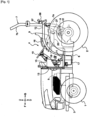
Fig. 1 is an overall side view of a tractor; -
Fig. 2 is an overall plan view of the tractor; -
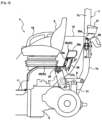
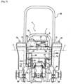
Fig. 3 is a longitudinal side view near a driving unit; -
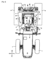
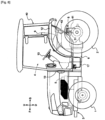
Fig. 4 is a back view of the tractor; -
Fig. 5 is an exploded perspective view near a control unit; -
Fig. 6 is an overall side view of the tractor, in a first alternative embodiment of the present invention; -
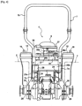
Fig. 7 is a back view of the tractor, in the first alternative embodiment of the present invention; -
Fig. 8 is an overall side view of the tractor, in a second alternative embodiment of the present invention; and -
Fig. 9 is a back view of the tractor, in the second alternative embodiment of the present invention. - The front and rear directions, and the left and right directions in this embodiment of the present invention indicated as follows, unless otherwise specified, F denotes the "front direction;" B denotes the "back direction;" U denotes the "upward direction" and D denotes the "downward direction." R denotes the "right direction," and L denotes the "left direction."
- As shown in
Figs. 1 , and2 , disposed are left and right front wheels 1, and left and rightrear wheels 2, and amachine body 3 supported by the front wheels 1 and therear wheels 2, and the driving unit 4 is supported by themachine body 3. Themain body 3 is equipped with an engine 5 at the front side, andtransmission case 6 at the rear side. The engine 5 andtransmission case 6 are linked. - The ROPS frame is linked to the rear portion of the
transmission case 6 and extends to the upward side. TheROPS frame 7 is arranged at a rear side of the driving unit 4. - The left and
lifter arms 8, and left andright lift cylinders 31 that rockingly drive the lifter arms are disposed behind thetransmission case 6. Each type of work device (not shown in the drawings) can be linked to the rear of thetransmission case 6. The work devices can be raised and lowered by thelifter arms 8. - As shown in
Figs. 1 , and2 , the driving unit 4 is equipped with a driver's seat 9, asteering wheel 10 for steering the front wheels 1, and afloor 11 arranged below the driving unit 4. The driving unit 4 is arranged behind the engine 5, and arranged above thetransmission case 6. -
Fenders 12 are disposed at the left and rightrear wheels 2. The left andright fenders 12 are arranged at left and right horizontal sides of the driver's seat 9. Apartitioning wall 13 is arranged between the driving unit 4, and the engine 5. Thesteering wheel 10 is arranged behind thepartitioning wall 13. - The space between the partitioning
wall 13 and theright fender 12 is an egress-ingress area 14 at a right side of the driving unit 4. The space between the partitioningwall 13 and theleft fender 12 is an egress-ingress area 14 at a left side of the driving unit 4. The driver egresses and ingresses the driving unit 4 mainly through the egress-ingress area 14 on the left side. - A
railing frame 15 is arranged in front of the left-side egress-ingress area 14 in the egress-ingress area 14.Handles 16 are linked above the left andright fenders 12.Step 17 is linked to the left side of thefloor 11, and step 17 is arranged below the egress-ingress area 14. - With the structure described above, the driver will grab the
railing frame 15 with their left hand, and grab thehandle 16 on the left andright fenders 12, at the left side egress-ingress area 14, place their foot on thestep 17 and egress-ingress to the driving unit 4. - As depicted in
Figs. 1 ,2 and3 , asupport member 20 is disposed behind themachine body 3, and a lower portion of the driver's seat 9 (a seat) is supported by thesupport member 20. - A
lever guide 19 is disposed at a left, top side of thesupport member 20 and between the driver's seat 9 and leftfender 12. Aparking brake lever 18, operation handle 22 and agear shifting lever 23 are arranged on thelever guide 19. - The
parking brake lever 18 can implement operations to release and engage the brake of the parking brake (not shown in the drawings) disposed in thetransmission case 6. - The operation lever 22 can block the transmission of motive power to the front wheels 1 and set to a two-wheel drive state in which only the
rear wheels 2 are driven, or to a four-wheel drive state in which the front wheels 1 and therear wheels 2 are driven. - A gear shifter (not shown in the drawings) for travel is disposed in the
transmission case 6. The gear shifter for travel can be operated for 3 gears for forward and 1 gear for reverse. Thegear shifting lever 23 can operate the gear shifter for travel. - As depicted in
Figs. 3 ,4 and5 , thesupport member 20 is equipped with afront portion 25 and arear portion 26. Thefront portion 25 and therear portion 26 of thesupport member 20 span the left andright fenders 12. With this, the left and right left and right rear-wheel fenders 12 disposed at the left and right lateral side portions for thefront portion 25 and therear portion 26 of thesupport member 20. - A
bracket 21 is linked to the left and right portions behind thetransmission case 6. Thefront portion 25 of thesupport member 20 is arranged facing laterally; thesupport member 20 is supported by themachine body 3 via a vibration-insulation member 24 and the bracket 21 A bottom (a seat) of the driver's seat 9 is supported by thefront portion 25 of thesupport member 20; therear portion 26 of thesupport member 20 is a portion of the rear side of the driver's seat 9. - The
rear portion 26 of thesupport member 20 is equipped with avertical face portion 26a along left and right directions connected to a rear-end portion of thefront portion 25 of thesupport member 20, and alateral face portion 26b along left and right directions connected to a top portion of thevertical face portion 26a. With this, therear portion 26 of thesupport member 20 has a step-shaped rear rising shape when seen in side view. - As shown in
Figs. 3 ,4 , and5 , thecontrol unit 27 is supported between the left andright fenders 12 and at the lower side of the portion of therear portion 26 of thesupport member 20, and arranged at a rear side of thelever guide 19. - Specifically, at the
rear portion 26 of thesupport member 20, abracket 32 is linked to a rear face of the left portion of thevertical face portion 26a, and thecontrol unit 27 is mounted to thebracket 32. With this, thecontrol unit 27 is arranged at a lower side of thelateral face portion 26b at therear portion 26 of thesupport member 20. - In such a case, it is acceptable to link the
bracket 32 to a lower face of the left portion of thelateral face portion 26b, in therear portion 26 of thesupport member 20, and to mouth thecontrol unit 27 to thebracket 32. With this, thecontrol unit 27 is arranged at a rear side of thevertical face portion 26a at therear portion 26 of thesupport member 20. - Left and
right lifter arms 8 are arranged at a lower side of therear portion 26 of thesupport member 20. Thecontrol unit 27 is supported to touch theleft fender 12. With this, thecontrol unit 27 is in a state supported between theleft fender 12 and theleft lifter arm 8 when seen in the plan view. InFig. 4 , when thelifter arm 8 rises up to its upper limit position, thecontrol unit 27 is supported between thefender 12 and theleft lifter arm 8 when seen from the back side. - In such a case, it is acceptable to support the
control unit 27 to touch the right fender, and so that thecontrol unit 27 is supported between theright fender 12 and theright lifter arm 8 when seen in the plan view. - A
cover 28 is mounted to thebracket 32 by abolt 33 at theear portion 26 of thesupport member 20. A rear side of thecontrol unit 27 is covered by thecover 28. Thecover 28 can be removed by removing thebolt 33. - A
connector 27a of thecontrol unit 27 is disposed facing downward at a lower portion of thecontrol unit 27. A portion of a lower side opposing theconnector 27a of thecontrol unit 27 is open, in thecover 28. Aconnector 27a of thecontrol unit 27 is arranged in the portion open at a lower side of thecover 28. - As shown in
Figs. 3 and4 , the ROPS frame is equipped with left andright base portions 7a, and a loop-shapedtop portion 7b. - Left and right rear
wheel axle cases 29 are linked to the rear of thetransmission case 6. Therear wheels 2 are supported by the rearwheel axle case 29. Abracket 30 is linked to the rearwheel axle case 29. Thebase portion 7a of the POPS frame is linked to thebracket 30, and theROPS frame 7 extends to a top side. Thebase portion 7a of thePOPS frame 7 is arranged along up and down directions at the rear side of thecontrol unit 27 andcover 28. - A
frame 35 is linked across a top portion of the left andright base portions 7a of thePOPS frame 7. A lateral-facingframe 36 is linked to an upper portion of theframe 35, and atool box 37 is linked to left and right upward facingbrackets 36a of theframe 36. Asupport plate 38 for mounting a license plate (not shown in the drawings) is connected to a left portion of theframe 36. - A
frame 35 connected across a top portion of the left andright base portions 7a of thePOPS frame 7 is arranged at an upper side at a rear side of thecontrol unit 27 andcover 28. - The
frames tool box 37, and thesupport plate 38 are arranged further at the upper side than thehorizontal face portion 26b at therear portion 26 of thesupport member 20 when seen from the back side. With this, a worker standing at the rear side of thetransmission case 6 cannot work using theframes tool box 37, andsupport plate 38 even if they extend their hand to the driving unit 4. - As shown in
Figs. 6 and7 , theROPS frame 7 is constituted to be low, so that theupper portion 7b of theROPS frame 7 is arranged at a position that is substantially the same height as the upper end portion of the backrest of the driver's seat 9. Theframe 35 shown inFigs. 3 and4 is removed, and theframe 36 linked with thetool box 37 is connected across the left andright base portions 7a of theROPS frame 7. In such a case, a high-back ROPS frame 39 is disposed at a front portion of the driving unit 4. TheROPS frame 39 extends to an upper side along the left and right sides of thepartitioning wall 13. - With the tractor depicted in
Figs. 8 and9 , thecabin 40 is disposed that covers the driving unit 4. In such a case, as shown inFigs. 2 ,3 and4 , thesupport member 20 is connected to thecabin 40. - A
bracket 41 is connected to left and right rearwheel axle cases 29. Left and right support frames 42 extend facing downward at a rear portion of thecabin 40. A lower portion of thesupport frame 42 is supported by thebracket 41 via the vibration-insulation member 24. - With this, the
support member 20 that supports thecontrol unit 27 is supported by themachine body 3 by the vibration-insulation member 24 via thecabin 40. Thecontrol unit 27 is arranged at an outside of thecabin 40. - The
support frame 42 is arranged in up and down directions to touch thefenders 12. With this, thecontrol unit 27 is supported at a lower side on the left portion of therear portion 26 of thesupport member 20, and between the left and right support frames 42 when seen from the back side. - It is acceptable to support the
control unit 27 between the left andright fenders 12 and at a lower side at a right portion of therear portion 26 of thesupport member 20. - It is acceptable to form the
rear portion 26 of thesupport member 20 to be plate shaped with a rising rear shape, by removing thevertical face portion 26a and thelateral face portion 26b of therear portion 26 of thesupport member 20. it is also acceptable to form therear portion 26 of thesupport member 20 to be plate shaped along a horizontal face, and not to have a rising rear shape. - The present invention can be applied to a tractor.
-
- 2
- Rear wheel
- 3
- Machine body
- 7
- ROPS frame
- 7a
- Base portion of ROPS frame
- 8
- Lifter arm
- 9
- Driver's seat
- 12
- Fender
- 20
- Support member
- 24
- Vibration-insulation member
- 26
- Rear portion of support member
- 26a
- Vertical face portion of rear portion of support member
- 26b
- Lateral face portion of rear portion of support member
- 27
- Control unit
- 27a
- Control unit connector
- 28
- Cover
- 35, 36
- Frame
- 37
- Tool box
Claims (7)
- A tractor comprising:a support member (20) disposed in a rear portion of a machine body (3), for supporting a lower portion of a driver's seat (9);left and right rear-wheel fenders (12) disposed at left and right lateral side portions of the support member (20); anda control unit (27) supported between the left and right fenders (12), and at a lower side of a rear portion of a rear side of the driver's seat (9) in the support member (20);characterized in thata cover (28) that covers the rear side of the control unit (27) is disposed, anda connector is disposed facing downward at a lower portion of the control unit (27) and a portion opposing the connector in the cover (28) is open.
- The tractor according to claim 1, wherein the rear portion of the support member (20) is disposed with a vertical face portion along left and right directions, and a lateral face portion along left and right directions, and has a shape rising rearwards when seen in side view; and the control unit (27) is supported at a lower side of the lateral face portion, at a rear side of the vertical face portion.
- The tractor according to claim 1 or claim 2, wherein a lifter arm (8) that freely swings up and down is disposed at the lower side of the rear portion of the support member (20), and the control unit (27) is supported between the left or right fender (12) and the lifter arm (8) when seen in the plan view.
- The tractor according to any one of claims 1 to claim 3, wherein the control unit (27) is supported by the machine body (3) via a vibration-insulation member (24).
- The tractor according to any one of claim 1 to claim 4, wherein a base of a ROPS frame (7a) is connected to the rear portion of the machine body (3), the ROPS frame (7) extending to an upper side; and the base portion is arranged at a rear side of the control unit (27).
- The tractor according to claim 5, wherein the base portion comprises a left and right base portion and wherein a frame (35, 36) along the left and right directions is connected across the left and right base portions, such that the frame (35, 36) is positioned at an upper side of the control unit (27) when viewed from the back side.
- The tractor according to claim 6, wherein a tool box (37) is supported on the frame (35, 36) such that the tool box (37) is positioned at an upper side of the frame (35, 36).
Applications Claiming Priority (1)
| Application Number | Priority Date | Filing Date | Title |
|---|---|---|---|
| JP2017197018A JP6858685B2 (en) | 2017-10-10 | 2017-10-10 | Tractor |
Publications (3)
| Publication Number | Publication Date |
|---|---|
| EP3470583A2 EP3470583A2 (en) | 2019-04-17 |
| EP3470583A3 EP3470583A3 (en) | 2019-06-26 |
| EP3470583B1 true EP3470583B1 (en) | 2023-04-12 |
Family
ID=63896016
Family Applications (1)
| Application Number | Title | Priority Date | Filing Date |
|---|---|---|---|
| EP18194563.5A Active EP3470583B1 (en) | 2017-10-10 | 2018-09-14 | Tractor |
Country Status (2)
| Country | Link |
|---|---|
| EP (1) | EP3470583B1 (en) |
| JP (1) | JP6858685B2 (en) |
Families Citing this family (4)
| Publication number | Priority date | Publication date | Assignee | Title |
|---|---|---|---|---|
| EP3922094A1 (en) * | 2018-10-24 | 2021-12-15 | Kubota Corporation | Work vehicle with handle assembly |
| JP7335206B2 (en) * | 2020-06-29 | 2023-08-29 | 株式会社クボタ | work vehicle |
| JP2023085003A (en) * | 2021-12-08 | 2023-06-20 | 井関農機株式会社 | work vehicle |
| KR20230152566A (en) * | 2022-04-27 | 2023-11-03 | 얀마 홀딩스 주식회사 | Working vehicle |
Family Cites Families (8)
| Publication number | Priority date | Publication date | Assignee | Title |
|---|---|---|---|---|
| JPS617955Y2 (en) * | 1981-04-21 | 1986-03-11 | ||
| JP3692550B2 (en) * | 1994-10-11 | 2005-09-07 | 井関農機株式会社 | Mobile agricultural machine controller |
| JP2004175160A (en) * | 2002-11-25 | 2004-06-24 | Mitsubishi Agricult Mach Co Ltd | Movable agricultural machine |
| JP2008155771A (en) * | 2006-12-22 | 2008-07-10 | Yanmar Co Ltd | Arrangement structure for control device in working vehicle |
| JP2014148921A (en) * | 2013-01-31 | 2014-08-21 | Iseki & Co Ltd | Tractor |
| JP6121222B2 (en) | 2013-04-10 | 2017-04-26 | 株式会社クボタ | Power control device for hybrid work vehicle |
| JP6552320B2 (en) * | 2015-07-31 | 2019-07-31 | ヤンマー株式会社 | Tractor |
| US10480156B2 (en) * | 2015-12-14 | 2019-11-19 | Kubota Corporation | Work vehicle |
-
2017
- 2017-10-10 JP JP2017197018A patent/JP6858685B2/en active Active
-
2018
- 2018-09-14 EP EP18194563.5A patent/EP3470583B1/en active Active
Also Published As
| Publication number | Publication date |
|---|---|
| EP3470583A2 (en) | 2019-04-17 |
| JP2019069706A (en) | 2019-05-09 |
| JP6858685B2 (en) | 2021-04-14 |
| EP3470583A3 (en) | 2019-06-26 |
Similar Documents
| Publication | Publication Date | Title |
|---|---|---|
| EP3470583B1 (en) | Tractor | |
| KR101506521B1 (en) | Working vehicle | |
| JP6770801B2 (en) | Tractor | |
| JP2008155771A (en) | Arrangement structure for control device in working vehicle | |
| JP6920955B2 (en) | Tractor | |
| JP2001063640A (en) | Tractor | |
| US11702154B2 (en) | Work vehicle | |
| JP4478076B2 (en) | Tractor armrest structure | |
| JP2013215126A (en) | Riding-type paddy field implement | |
| JP3894608B2 (en) | Passenger-type management work vehicle | |
| JP2005170332A (en) | Cab for construction machine | |
| JPH04317875A (en) | Control panel of tractor | |
| JP4598571B2 (en) | Passenger rice transplanter | |
| EP3599530B1 (en) | Cabin front wall structure of vehicle | |
| JP4543245B2 (en) | Traveling vehicle | |
| JP4271357B2 (en) | Traveling vehicle | |
| JP7178938B2 (en) | work vehicle | |
| JPH0810248Y2 (en) | Balance weight of riding paddy work machine | |
| JPH082042Y2 (en) | Operation panel for passenger vehicles | |
| EP2821323B1 (en) | Working vehicle | |
| JP2024070662A (en) | Work vehicle | |
| JP2024070661A (en) | Work vehicle | |
| JP4796012B2 (en) | Tractor-mounted backhoe | |
| JP2024070663A (en) | Work vehicle | |
| JP2005137212A5 (en) |
Legal Events
| Date | Code | Title | Description |
|---|---|---|---|
| PUAI | Public reference made under article 153(3) epc to a published international application that has entered the european phase |
Free format text: ORIGINAL CODE: 0009012 |
|
| STAA | Information on the status of an ep patent application or granted ep patent |
Free format text: STATUS: THE APPLICATION HAS BEEN PUBLISHED |
|
| AK | Designated contracting states |
Kind code of ref document: A2 Designated state(s): AL AT BE BG CH CY CZ DE DK EE ES FI FR GB GR HR HU IE IS IT LI LT LU LV MC MK MT NL NO PL PT RO RS SE SI SK SM TR |
|
| AX | Request for extension of the european patent |
Extension state: BA ME |
|
| PUAL | Search report despatched |
Free format text: ORIGINAL CODE: 0009013 |
|
| AK | Designated contracting states |
Kind code of ref document: A3 Designated state(s): AL AT BE BG CH CY CZ DE DK EE ES FI FR GB GR HR HU IE IS IT LI LT LU LV MC MK MT NL NO PL PT RO RS SE SI SK SM TR |
|
| AX | Request for extension of the european patent |
Extension state: BA ME |
|
| RIC1 | Information provided on ipc code assigned before grant |
Ipc: B60R 11/00 20060101ALI20190521BHEP Ipc: E02F 9/08 20060101AFI20190521BHEP Ipc: B62D 49/00 20060101ALI20190521BHEP Ipc: E02F 9/16 20060101ALI20190521BHEP Ipc: B60R 16/023 20060101ALI20190521BHEP |
|
| STAA | Information on the status of an ep patent application or granted ep patent |
Free format text: STATUS: REQUEST FOR EXAMINATION WAS MADE |
|
| 17P | Request for examination filed |
Effective date: 20191219 |
|
| RBV | Designated contracting states (corrected) |
Designated state(s): AL AT BE BG CH CY CZ DE DK EE ES FI FR GB GR HR HU IE IS IT LI LT LU LV MC MK MT NL NO PL PT RO RS SE SI SK SM TR |
|
| GRAP | Despatch of communication of intention to grant a patent |
Free format text: ORIGINAL CODE: EPIDOSNIGR1 |
|
| STAA | Information on the status of an ep patent application or granted ep patent |
Free format text: STATUS: GRANT OF PATENT IS INTENDED |
|
| RIC1 | Information provided on ipc code assigned before grant |
Ipc: B60R 11/00 20060101ALI20221017BHEP Ipc: B62D 49/00 20060101ALI20221017BHEP Ipc: B60R 16/023 20060101ALI20221017BHEP Ipc: B60N 2/38 20060101ALI20221017BHEP Ipc: B60R 21/13 20060101ALI20221017BHEP Ipc: E02F 9/16 20060101ALI20221017BHEP Ipc: E02F 9/08 20060101AFI20221017BHEP |
|
| INTG | Intention to grant announced |
Effective date: 20221102 |
|
| GRAS | Grant fee paid |
Free format text: ORIGINAL CODE: EPIDOSNIGR3 |
|
| GRAA | (expected) grant |
Free format text: ORIGINAL CODE: 0009210 |
|
| STAA | Information on the status of an ep patent application or granted ep patent |
Free format text: STATUS: THE PATENT HAS BEEN GRANTED |
|
| AK | Designated contracting states |
Kind code of ref document: B1 Designated state(s): AL AT BE BG CH CY CZ DE DK EE ES FI FR GB GR HR HU IE IS IT LI LT LU LV MC MK MT NL NO PL PT RO RS SE SI SK SM TR |
|
| REG | Reference to a national code |
Ref country code: GB Ref legal event code: FG4D |
|
| REG | Reference to a national code |
Ref country code: CH Ref legal event code: EP |
|
| REG | Reference to a national code |
Ref country code: DE Ref legal event code: R096 Ref document number: 602018048263 Country of ref document: DE |
|
| REG | Reference to a national code |
Ref country code: IE Ref legal event code: FG4D |
|
| REG | Reference to a national code |
Ref country code: AT Ref legal event code: REF Ref document number: 1559856 Country of ref document: AT Kind code of ref document: T Effective date: 20230515 |
|
| REG | Reference to a national code |
Ref country code: LT Ref legal event code: MG9D |
|
| REG | Reference to a national code |
Ref country code: NL Ref legal event code: MP Effective date: 20230412 |
|
| REG | Reference to a national code |
Ref country code: AT Ref legal event code: MK05 Ref document number: 1559856 Country of ref document: AT Kind code of ref document: T Effective date: 20230412 |
|
| PG25 | Lapsed in a contracting state [announced via postgrant information from national office to epo] |
Ref country code: NL Free format text: LAPSE BECAUSE OF FAILURE TO SUBMIT A TRANSLATION OF THE DESCRIPTION OR TO PAY THE FEE WITHIN THE PRESCRIBED TIME-LIMIT Effective date: 20230412 |
|
| PG25 | Lapsed in a contracting state [announced via postgrant information from national office to epo] |
Ref country code: SE Free format text: LAPSE BECAUSE OF FAILURE TO SUBMIT A TRANSLATION OF THE DESCRIPTION OR TO PAY THE FEE WITHIN THE PRESCRIBED TIME-LIMIT Effective date: 20230412 Ref country code: PT Free format text: LAPSE BECAUSE OF FAILURE TO SUBMIT A TRANSLATION OF THE DESCRIPTION OR TO PAY THE FEE WITHIN THE PRESCRIBED TIME-LIMIT Effective date: 20230814 Ref country code: NO Free format text: LAPSE BECAUSE OF FAILURE TO SUBMIT A TRANSLATION OF THE DESCRIPTION OR TO PAY THE FEE WITHIN THE PRESCRIBED TIME-LIMIT Effective date: 20230712 Ref country code: ES Free format text: LAPSE BECAUSE OF FAILURE TO SUBMIT A TRANSLATION OF THE DESCRIPTION OR TO PAY THE FEE WITHIN THE PRESCRIBED TIME-LIMIT Effective date: 20230412 Ref country code: AT Free format text: LAPSE BECAUSE OF FAILURE TO SUBMIT A TRANSLATION OF THE DESCRIPTION OR TO PAY THE FEE WITHIN THE PRESCRIBED TIME-LIMIT Effective date: 20230412 |
|
| PG25 | Lapsed in a contracting state [announced via postgrant information from national office to epo] |
Ref country code: RS Free format text: LAPSE BECAUSE OF FAILURE TO SUBMIT A TRANSLATION OF THE DESCRIPTION OR TO PAY THE FEE WITHIN THE PRESCRIBED TIME-LIMIT Effective date: 20230412 Ref country code: PL Free format text: LAPSE BECAUSE OF FAILURE TO SUBMIT A TRANSLATION OF THE DESCRIPTION OR TO PAY THE FEE WITHIN THE PRESCRIBED TIME-LIMIT Effective date: 20230412 Ref country code: LV Free format text: LAPSE BECAUSE OF FAILURE TO SUBMIT A TRANSLATION OF THE DESCRIPTION OR TO PAY THE FEE WITHIN THE PRESCRIBED TIME-LIMIT Effective date: 20230412 Ref country code: LT Free format text: LAPSE BECAUSE OF FAILURE TO SUBMIT A TRANSLATION OF THE DESCRIPTION OR TO PAY THE FEE WITHIN THE PRESCRIBED TIME-LIMIT Effective date: 20230412 Ref country code: IS Free format text: LAPSE BECAUSE OF FAILURE TO SUBMIT A TRANSLATION OF THE DESCRIPTION OR TO PAY THE FEE WITHIN THE PRESCRIBED TIME-LIMIT Effective date: 20230812 Ref country code: HR Free format text: LAPSE BECAUSE OF FAILURE TO SUBMIT A TRANSLATION OF THE DESCRIPTION OR TO PAY THE FEE WITHIN THE PRESCRIBED TIME-LIMIT Effective date: 20230412 Ref country code: GR Free format text: LAPSE BECAUSE OF FAILURE TO SUBMIT A TRANSLATION OF THE DESCRIPTION OR TO PAY THE FEE WITHIN THE PRESCRIBED TIME-LIMIT Effective date: 20230713 Ref country code: AL Free format text: LAPSE BECAUSE OF FAILURE TO SUBMIT A TRANSLATION OF THE DESCRIPTION OR TO PAY THE FEE WITHIN THE PRESCRIBED TIME-LIMIT Effective date: 20230412 |
|
| PGFP | Annual fee paid to national office [announced via postgrant information from national office to epo] |
Ref country code: FR Payment date: 20230920 Year of fee payment: 6 Ref country code: DE Payment date: 20230920 Year of fee payment: 6 |
|
| PG25 | Lapsed in a contracting state [announced via postgrant information from national office to epo] |
Ref country code: FI Free format text: LAPSE BECAUSE OF FAILURE TO SUBMIT A TRANSLATION OF THE DESCRIPTION OR TO PAY THE FEE WITHIN THE PRESCRIBED TIME-LIMIT Effective date: 20230412 |
|
| REG | Reference to a national code |
Ref country code: DE Ref legal event code: R097 Ref document number: 602018048263 Country of ref document: DE |
|
| PG25 | Lapsed in a contracting state [announced via postgrant information from national office to epo] |
Ref country code: SK Free format text: LAPSE BECAUSE OF FAILURE TO SUBMIT A TRANSLATION OF THE DESCRIPTION OR TO PAY THE FEE WITHIN THE PRESCRIBED TIME-LIMIT Effective date: 20230412 |
|
| PG25 | Lapsed in a contracting state [announced via postgrant information from national office to epo] |
Ref country code: SM Free format text: LAPSE BECAUSE OF FAILURE TO SUBMIT A TRANSLATION OF THE DESCRIPTION OR TO PAY THE FEE WITHIN THE PRESCRIBED TIME-LIMIT Effective date: 20230412 Ref country code: SK Free format text: LAPSE BECAUSE OF FAILURE TO SUBMIT A TRANSLATION OF THE DESCRIPTION OR TO PAY THE FEE WITHIN THE PRESCRIBED TIME-LIMIT Effective date: 20230412 Ref country code: RO Free format text: LAPSE BECAUSE OF FAILURE TO SUBMIT A TRANSLATION OF THE DESCRIPTION OR TO PAY THE FEE WITHIN THE PRESCRIBED TIME-LIMIT Effective date: 20230412 Ref country code: EE Free format text: LAPSE BECAUSE OF FAILURE TO SUBMIT A TRANSLATION OF THE DESCRIPTION OR TO PAY THE FEE WITHIN THE PRESCRIBED TIME-LIMIT Effective date: 20230412 Ref country code: DK Free format text: LAPSE BECAUSE OF FAILURE TO SUBMIT A TRANSLATION OF THE DESCRIPTION OR TO PAY THE FEE WITHIN THE PRESCRIBED TIME-LIMIT Effective date: 20230412 Ref country code: CZ Free format text: LAPSE BECAUSE OF FAILURE TO SUBMIT A TRANSLATION OF THE DESCRIPTION OR TO PAY THE FEE WITHIN THE PRESCRIBED TIME-LIMIT Effective date: 20230412 |
|
| PLBE | No opposition filed within time limit |
Free format text: ORIGINAL CODE: 0009261 |
|
| STAA | Information on the status of an ep patent application or granted ep patent |
Free format text: STATUS: NO OPPOSITION FILED WITHIN TIME LIMIT |
|
| 26N | No opposition filed |
Effective date: 20240115 |
|
| REG | Reference to a national code |
Ref country code: CH Ref legal event code: PL |
|
| PG25 | Lapsed in a contracting state [announced via postgrant information from national office to epo] |
Ref country code: SI Free format text: LAPSE BECAUSE OF FAILURE TO SUBMIT A TRANSLATION OF THE DESCRIPTION OR TO PAY THE FEE WITHIN THE PRESCRIBED TIME-LIMIT Effective date: 20230412 |
|
| PG25 | Lapsed in a contracting state [announced via postgrant information from national office to epo] |
Ref country code: LU Free format text: LAPSE BECAUSE OF NON-PAYMENT OF DUE FEES Effective date: 20230914 |
|
| REG | Reference to a national code |
Ref country code: BE Ref legal event code: MM Effective date: 20230930 |
|
| GBPC | Gb: european patent ceased through non-payment of renewal fee |
Effective date: 20230914 |
|
| PG25 | Lapsed in a contracting state [announced via postgrant information from national office to epo] |
Ref country code: SI Free format text: LAPSE BECAUSE OF FAILURE TO SUBMIT A TRANSLATION OF THE DESCRIPTION OR TO PAY THE FEE WITHIN THE PRESCRIBED TIME-LIMIT Effective date: 20230412 Ref country code: IT Free format text: LAPSE BECAUSE OF FAILURE TO SUBMIT A TRANSLATION OF THE DESCRIPTION OR TO PAY THE FEE WITHIN THE PRESCRIBED TIME-LIMIT Effective date: 20230412 Ref country code: LU Free format text: LAPSE BECAUSE OF NON-PAYMENT OF DUE FEES Effective date: 20230914 Ref country code: MC Free format text: LAPSE BECAUSE OF FAILURE TO SUBMIT A TRANSLATION OF THE DESCRIPTION OR TO PAY THE FEE WITHIN THE PRESCRIBED TIME-LIMIT Effective date: 20230412 |
|
| REG | Reference to a national code |
Ref country code: IE Ref legal event code: MM4A |
|
| PG25 | Lapsed in a contracting state [announced via postgrant information from national office to epo] |
Ref country code: IE Free format text: LAPSE BECAUSE OF NON-PAYMENT OF DUE FEES Effective date: 20230914 |
|
| PG25 | Lapsed in a contracting state [announced via postgrant information from national office to epo] |
Ref country code: GB Free format text: LAPSE BECAUSE OF NON-PAYMENT OF DUE FEES Effective date: 20230914 |
|
| PG25 | Lapsed in a contracting state [announced via postgrant information from national office to epo] |
Ref country code: CH Free format text: LAPSE BECAUSE OF NON-PAYMENT OF DUE FEES Effective date: 20230930 |
|
| PG25 | Lapsed in a contracting state [announced via postgrant information from national office to epo] |
Ref country code: IE Free format text: LAPSE BECAUSE OF NON-PAYMENT OF DUE FEES Effective date: 20230914 Ref country code: GB Free format text: LAPSE BECAUSE OF NON-PAYMENT OF DUE FEES Effective date: 20230914 Ref country code: CH Free format text: LAPSE BECAUSE OF NON-PAYMENT OF DUE FEES Effective date: 20230930 |
|
| PG25 | Lapsed in a contracting state [announced via postgrant information from national office to epo] |
Ref country code: BE Free format text: LAPSE BECAUSE OF NON-PAYMENT OF DUE FEES Effective date: 20230930 |