EP3470306B1 - Vehicle body structure - Google Patents
Vehicle body structure Download PDFInfo
- Publication number
- EP3470306B1 EP3470306B1 EP18198853.6A EP18198853A EP3470306B1 EP 3470306 B1 EP3470306 B1 EP 3470306B1 EP 18198853 A EP18198853 A EP 18198853A EP 3470306 B1 EP3470306 B1 EP 3470306B1
- Authority
- EP
- European Patent Office
- Prior art keywords
- vehicle
- frame
- width direction
- vehicle width
- cutout
- Prior art date
- Legal status (The legal status is an assumption and is not a legal conclusion. Google has not performed a legal analysis and makes no representation as to the accuracy of the status listed.)
- Active
Links
Images





Classifications
-
- B—PERFORMING OPERATIONS; TRANSPORTING
- B60—VEHICLES IN GENERAL
- B60R—VEHICLES, VEHICLE FITTINGS, OR VEHICLE PARTS, NOT OTHERWISE PROVIDED FOR
- B60R19/00—Wheel guards; Radiator guards, e.g. grilles; Obstruction removers; Fittings damping bouncing force in collisions
- B60R19/02—Bumpers, i.e. impact receiving or absorbing members for protecting vehicles or fending off blows from other vehicles or objects
- B60R19/24—Arrangements for mounting bumpers on vehicles
- B60R19/26—Arrangements for mounting bumpers on vehicles comprising yieldable mounting means
- B60R19/34—Arrangements for mounting bumpers on vehicles comprising yieldable mounting means destroyed upon impact, e.g. one-shot type
-
- B—PERFORMING OPERATIONS; TRANSPORTING
- B62—LAND VEHICLES FOR TRAVELLING OTHERWISE THAN ON RAILS
- B62D—MOTOR VEHICLES; TRAILERS
- B62D21/00—Understructures, i.e. chassis frame on which a vehicle body may be mounted
- B62D21/15—Understructures, i.e. chassis frame on which a vehicle body may be mounted having impact absorbing means, e.g. a frame designed to permanently or temporarily change shape or dimension upon impact with another body
- B62D21/152—Front or rear frames
-
- B—PERFORMING OPERATIONS; TRANSPORTING
- B62—LAND VEHICLES FOR TRAVELLING OTHERWISE THAN ON RAILS
- B62D—MOTOR VEHICLES; TRAILERS
- B62D25/00—Superstructure or monocoque structure sub-units; Parts or details thereof not otherwise provided for
- B62D25/08—Front or rear portions
-
- B—PERFORMING OPERATIONS; TRANSPORTING
- B62—LAND VEHICLES FOR TRAVELLING OTHERWISE THAN ON RAILS
- B62D—MOTOR VEHICLES; TRAILERS
- B62D25/00—Superstructure or monocoque structure sub-units; Parts or details thereof not otherwise provided for
- B62D25/08—Front or rear portions
- B62D25/082—Engine compartments
Definitions
- the technique disclosed in the present specification relates to a vehicle body structure including a frame extending in a vehicle longitudinal direction outside a power train in a vehicle width direction, the power train being mounted on a front portion of a vehicle.
- a frame a front side frame and/or an extension frame extending from a suspension cross member to a vehicle front side
- One form of front collision of the vehicle may include collision with an obstacle outside the front side frame of the vehicle in a vehicle width direction, and such front collision is called "small overlap collision.”
- a load receiving portion protruding outward in the vehicle width direction is provided at a portion extending from a front end of the front side frame to the vicinity thereof (see, e.g., Japanese Patent No. 5357953 ).
- Document JP 2015-217898 A discloses a frame structure for a vehicle including left and right frames connected to each other via a coupling cross member, eacho f said frames being provided with a load receiving portion expanding outwards from a front end of the frame.
- Each frame has an open front end, wherein a crush can connected to a cross bumper beam is inserted into the open front end of said frames.
- Further frame structures for vehicles having such outwardly extending load receiving portions are known from EP 29 21 377 A1 and DE 10 2013 208 144 A1 .
- the frame upon small overlap collision of the vehicle, the frame might be bent inward in the vehicle width direction by the impact load input to the load receiving portion, and accordingly, might come into contact with the power train.
- a front portion of the vehicle By such contact, a front portion of the vehicle might be moved to a side away from the obstacle in the vehicle width direction such that transfer of the impact load to the inside of a vehicle compartment of the vehicle is reduced.
- the impact load input to the load receiving portion acts such that a portion outside the cutout portion in the vehicle width direction at the portion extending from the vehicle-front-side end of the frame to the vicinity thereof is separated outward and backward in the vehicle width direction from an inner portion of the cutout portion in the vehicle width direction, and accordingly, the cutout portion more easily expands in the vehicle width direction.
- the technique disclosed herein is intended to provide a vehicle body structure configured such that a cutout portion cut out from a vehicle-front-side end surface of a frame to a vehicle rear side as viewed in plane is formed at the end surface to reduce the weight of the frame and expansion of the cutout portion in a vehicle width direction is reduced upon small overlap collision of a vehicle to efficiently transfer impact load input to a load receiving portion to the frame.
- the vehicle body structure includes a frame extending in a vehicle longitudinal direction outside a power train in a vehicle width direction, the power train being mounted on a front portion of a vehicle.
- the vehicle body structure further includes a load receiving portion expanding outward in the vehicle width direction from a front end of the frame and configured to receive impact load acting upon front collision of the vehicle outside the frame in the vehicle width direction, a cutout portion provided at the front end of the frame and cut out rearwardly from the front end of the frame to leave two side portions, and a connection member connecting the side portions of the cutout portion in the vehicle width direction.
- both side portions of the cutout portion in the vehicle width direction are connected to each other by the connection member, and therefore, expansion of the cutout portion in the vehicle width direction can be reduced when the impact load is input to the load receiving portion in small overlap collision of the vehicle.
- the impact load input to the load receiving portion can be efficiently transferred to the frame.
- the frame is, through a coupling cross member extending in the vehicle width direction, coupled to an opposing frame extending in the vehicle longitudinal direction at the opposite side of the power train from the frame, and a vehicle-front-side opening end of the cutout portion is positioned closer to the vehicle front side with respect to the coupling cross member.
- the cutout portion more easily expands in the vehicle width direction when the impact load is input to the load receiving portion, but both side portions of the cutout portion in the vehicle width direction are connected to each other by the connection member.
- expansion of the cutout portion in the vehicle width direction can be reduced.
- the frame is curved to protrude inward in the vehicle width direction at the vehicle rear side of the load receiving portion.
- the frame is easily bent inward in the vehicle width direction when the impact load is input to the load receiving portion, and by such bending, the frame can come into contact with the power train.
- the front portion of the vehicle can be moved to a side away from an obstacle in the vehicle width direction.
- transfer of the impact load upon small overlap collision of the vehicle to the inside of a vehicle compartment of the vehicle can be reduced.
- the frame comes into contact with the power train before being sufficiently bent.
- the impact load input to the load receiving portion acts such that a portion outside the cutout portion in the vehicle width direction at the portion extending from the vehicle-front-side end of the frame to the vicinity thereof is separated outward in the vehicle width direction and backward from an inner portion of the cutout portion in the vehicle width direction, and accordingly, the cutout portion more easily expands in the vehicle width direction.
- both side portions of the cutout portion in the vehicle width direction are connected to each other by the connection member, and therefore, expansion of the cutout portion in the vehicle width direction can be reduced even in the case of the small clearance in the vehicle width direction between the frame and the power train.
- a set plate provided at a vehicle-rear-side end surface of a crash can is, with a bolt, fastened to the vehicle-front-side end surface of the frame, and the connection member is welded and joined to both side portions of the cutout portion in the vehicle width direction.
- the set plate can also reduce, in addition to the connection member, expansion of the cutout portion in the vehicle width direction upon small overlap collision of the vehicle.
- the set plate is fastened with the bolt, and therefore, is auxiliary.
- the welded and joined connection member reduces expansion of the cutout portion in the vehicle width direction.
- connection member is preferably provided in the vicinity of a vehicle-front-side opening end of the cutout portion.
- This can suppress the substantially entirety of the cutout portion in the vehicle longitudinal direction from expanding in the vehicle width direction upon small overlap collision of the vehicle, and the impact load input to the load receiving portion can be more efficiently transferred to the frame.
- FIGS. 1 to 3 illustrate a main portion of a front portion of a vehicle 1 to which a vehicle body structure according to the exemplary embodiment is applied.
- a power train 5 configured to drive right and left front wheels 3 of the vehicle 1 is arranged.
- the power train 5 includes an engine 6 and a transmission 7 to which torque (power) generated by the engine 6 is input.
- the front, rear, right, left, top, and bottom of the vehicle 1 will be each simply referred to as "front, rear, right, left, top, and bottom.”
- the engine 6 and the transmission 7 are arranged in a vehicle width direction (a right-to-left direction) between right and left front side frames 11 in a pair as described above.
- the engine 6 is positioned at the right of the transmission 7.
- a bottom end portion of the engine 6 includes an oil pan 6a (see FIG. 3 ).
- the right and left front side frames 11 formed in a pair with a substantially rectangular closed sectional shape and extending in a vehicle longitudinal direction are each arranged at both end portions of the engine room 2 in the vehicle width direction.
- a dash panel 13 (see FIG. 2 ) separating the engine room 2 and a vehicle compartment 12 is provided at a rear end portion of the engine room 2.
- a cowl member 14 is joined to a top end portion of the dash panel 13.
- Rear end portions of right and left apron reinforcement members 19 extending in the vehicle longitudinal direction are each coupled to both end portions of the cowl member 14 in the vehicle width direction.
- Wheel house panels 17 and suspension towers 18 are each provided outside the right and left front side frames 11 in the vehicle width direction.
- Each wheel house panel 17 is formed in an arc shape to cover the top side of the front wheel 3, and a front wheel house is formed inside such an arc.
- Bottom end portions of the right and left suspension towers 18 are each fixed to the right and left front side frames 11, and top end portions of the right and left suspension towers 18 are each fixed to the right and left apron reinforcement members 19.
- the power train 5 is elastically supported by the pair of right and left front side frames 11 through a right mount device 25 and a left mount device 21 at both end portions of the power train 5 such that a longitudinal direction of the power train 5 is along the vehicle width direction.
- the left mount device 21 has a power train side coupling member 22 coupled to a top portion of a left end portion of the transmission 7, a vehicle body side coupling member 23 coupled to the left front side frame 11 and the left wheel house panel 17, and a rubber bush (not shown) arranged between these coupling members 22, 23.
- the top portion of the left end portion of the transmission 7 is elastically supported by the left front side frame 11.
- the right mount device 25 has a power train side coupling member 26 coupled to a top portion of a right end portion of the engine 6, a vehicle body side coupling member 27 coupled to the right front side frame 11 and the right wheel house panel 17, and a rubber bush (not shown) arranged between these coupling members 26, 27.
- a power train side coupling member 26 coupled to a top portion of a right end portion of the engine 6,
- a vehicle body side coupling member 27 coupled to the right front side frame 11 and the right wheel house panel 17, and a rubber bush (not shown) arranged between these coupling members 26, 27.
- Crash cans 31 are each provided on front end surfaces of the right and left front side frames 11, and front end surfaces of these right and left crash cans 31 are each fixed to both right and left end portions of bumper beams 32 extending in the vehicle width direction.
- a suspension cross member 34 extending in the vehicle width direction below the right and left front side frames 11 is arranged slightly at the rear side of the suspension towers 18.
- the suspension cross member 34 includes a top member 35 and a bottom member 36 joined to each other at peripheral edge portions.
- the suspension cross member 34 has a body portion 34a extending in the vehicle width direction and front extension portions 34b extending inclined outward in the vehicle width direction from front edges of both right and left end portions of the body portion 34a toward the front side.
- the right and left front extension portions 34b are formed in a substantially rectangular closed sectional shape by the top member 35 and the bottom member 36.
- the right and left front wheels 3 are supported by the body portion 34a of the suspension cross member 34 through right and left suspension arms 39 (lower arms) forming part of a front wheel suspension.
- the right and left front wheels 3 are each supported by one end portions (outer end portions in the vehicle width direction) of the right and left suspension arms 39, and the other end portions (inner end portions in the vehicle width direction) of the right and left suspension arms 39 are each supported at both right and left end portions of a rear portion of the body portion 34a through rubber bushes by shafts 40 (see FIG. 3 ) extending in a top-to-bottom direction.
- middle portions of the suspension arms 39 in a longitudinal direction thereof are each supported at the right and left front extension portions 34b through rubber bushes by shafts extending in the vehicle longitudinal direction.
- Top extension portions (not shown) extending upward are each provided on top surfaces of the right and left front extension portions 34b, and top end portions of these right and left top extension portions are each fixed to bottom surfaces of the right and left front side frames 11.
- a torque rod support portion 34c is provided to rotatably support, about an axis extending in the vehicle width direction, a torque rod 29 provided at a portion of a bottom surface of the engine 6 in the vicinity of the transmission 7.
- Extension frames 41 formed in a substantially rectangular closed sectional shape and extending in the vehicle longitudinal direction at positions below the right and left front side frames 11 are linked to front end portions of the right and left front extension portions 34b.
- Each of the right and left extension frames 41 includes an outer member 41a positioned outside in the vehicle width direction, and an inner member 41b positioned inside in the vehicle width direction.
- the outer member 41a and the inner member 41b are in a substantially U-shaped sectional shape, and are welded and joined with openings of these U-shapes facing each other.
- the right and left extension frames 41 are at the substantially same position as that of the right and left front side frames 11 in the vehicle width direction.
- each extension frame 41 is welded and joined to a corresponding one of the front extension portions 34b (the top member 35 and the bottom member 36) with the rear end portion being inserted into the closed section of the corresponding one of the front extension portions 34b. That is, the rear end portion of each extension frame 41 is welded and joined with the rear end portion overlapping with the suspension cross member 34 in the vehicle longitudinal direction.
- a crash can 45 similar to the crash can 31 provided at a front end of each front side frame 11 is provided on a front end surface of each extension frame 41.
- a set plate 45a is provided on a rear end surface of each crash can 45, and is fastened and fixed to the front end surface of each extension frame 41 (specifically, an outer portion 55b and an inner portion 55c of a later-described front member 55) with multiple (three in the present exemplary embodiment) bolts 60 (illustrated only in FIGS. 5 and 6 ).
- the front end surfaces of the right and left crash cans 45 are, at positions below the bumper beams 32, each fixed to both right and left end portions of a stiffener 46 extending in the vehicle width direction.
- the stiffener 46 is configured to contact bottom portions of the legs of a pedestrian colliding with a front surface of the vehicle 1 to sweep these legs, thereby causing the pedestrian to fall over a bonnet of the vehicle 1. This prevents occurrence of an injury of the legs of the pedestrian, such as bone fracture, as much as possible.
- front portions of the bumper beams 32 and the stiffener 46 are covered with a not-shown front bumper.
- a cutout portion 41c cut out rearwardly in a rectangular shape from the front end of each extension frame 41 to leave two side portions as viewed in plane is formed at the front end surface of each extension frame 41.
- the cutout portion 41c is for weight reduction of the extension frame 41.
- the front end portions of the right and left extension frames 41 are coupled to each other by a coupling cross member 43 extending in the vehicle width direction.
- the body portion 34a and the right and left front extension portions 34b of the suspension cross member 34, the right and left extension frames 41, and the coupling cross member 43 form a perimeter frame in a substantially rectangular shape as viewed in plane.
- a load receiving portion 53 expanded outward in the vehicle width direction from the front end of the extension frame 41 and configured to receive impact load upon front collision of the vehicle 1 outside the extension frame 41 in the vehicle width direction (i.e., outside the front side frame 11 in the vehicle width direction) is provided. That is, when so-called small overlap collision occurs, i.e., a portion of the front surface (specifically, the front bumper) of the vehicle 1 outside the extension frame 41 in the vehicle width direction and an obstacle 71 (see FIGS. 8 and 9 ) collide with each other, such impact load is input to the load receiving portion 53.
- each extension frame 41 includes a plate-shaped body member 54 having a substantially U-shaped section cut at a plane along the vehicle width direction and bent such that an opening of the U-shape faces inward in the vehicle width direction, and part (the later-described outer portion 55b) of the front member 55 forming the front end surface of the extension frame 41.
- the body member 54 has a top portion 54a welded and joined to a top surface of the extension frame 41, and a bottom portion 54b (see FIG. 3 ) welded and joined to a bottom surface of the extension frame 41 with the bottom portion 54b facing the top portion 54a.
- the top portion 54a and the bottom portion 54b are in a substantially triangular shape having the same size as viewed in plane, and have front edges extending straight outward in the vehicle width direction and rear edges extending inclined inward in the vehicle width direction from protruding tip ends of the front edges to the rear side.
- the rear edges of the top portion 54a and the bottom portion 54b are coupled to each other by a rear portion 54c formed integrally with the top portion 54a and the bottom portion 54b.
- the body member 54 forms part of the extension frame 41.
- the front member 55 has a cutout formation portion 55a forming both side portions of the cutout portion 41c in the vehicle width direction and a rear end portion of the cutout portion 41c and formed in a substantially U-shape as viewed in plane, and the outer portion 55b and the inner portion 55c each extending outward and inward from both end portions of the U-shaped cutout formation portion 55a in the vehicle width direction. That is, the front member 55 is in a hat shape as viewed in plane. A front opening end (i.e., an opening end of the U-shaped cutout formation portion 55a) of the cutout portion 41c, the outer portion 55b, and the inner portion 55c are positioned closer to the front side with respect to the coupling cross member 43.
- the outer portion 55b forms a front portion of the load receiving portion 53, and is welded and joined to a front end surface of the body member 54 (specifically, front edges of the top portion 54a and the bottom portion 54b).
- the inner portion 55c is welded and joined to a front end surface of the inner member 41b of the extension frame 41.
- the set plate 45a of the crash can 45 is fastened to the outer portion 55b and the inner portion 55c with the bolts 60.
- the cutout formation portion 55a is welded and joined to both of the body member 54 and the inner member 41b.
- the cutout formation portion 55a extends upward of top surfaces of the outer member 41a and the inner member 41b of the extension frame 41, and a fixing member 51 for fixing to the front side frame 11 positioned above the extension frame 41 is provided at a top end of the cutout formation portion 55a.
- the fixing member 51 has a plate material 51a welded and joined to the top end of the cutout formation portion 55a to close a top opening of the cutout portion 41c, and a pin member 51b extending upward to allow insertion from the plate material 51a into the front side frame 11 and fixed to a member provided inside the front side frame 11. With this configuration, each extension frame 41 is fixed to a corresponding one of the front side frames 11 through the front member 55 and the fixing member 51.
- Each extension frame 41 is curved to protrude inward in the vehicle width direction at the rear side of the load receiving portion 53. This is because the extension frame 41 is easily bent inward in the vehicle width direction when the impact load is input to the load receiving portion 53.
- the left extension frame 41 is equivalent to a frame included in the vehicle body structure of the present invention
- the right extension frame 41 is equivalent to an opposing frame extending in the vehicle longitudinal direction at the opposite side of the power train 5 from the left extension frame 41.
- a configuration of the left extension frame 41 and deformation of the left extension frame 41 upon small overlap collision at a left portion of the front surface of the vehicle 1 will be described.
- the left extension frame 41 extends in the vehicle longitudinal direction outside (the left side) the power train 5 (the transmission 7) in the vehicle width direction.
- a case bottom end portion 7a of the transmission 7 is at the same height position as that of the left extension frame 41 (see FIG. 2 ).
- a clearance in the vehicle width direction between the left extension frame 41 and the power train 5 (the case bottom end portion 7a) is smaller than a clearance in the vehicle width direction between the right extension frame 41 and the power train 5 (the oil pan 6a at the same height position as that of the right extension frame 41).
- connection member 65 In the vicinity of the front opening end in the cutout portion 41c of the left extension frame 41, a plate-shaped connection member 65 connecting both side portions of the cutout portion 41c in the vehicle width direction (two surfaces of the cutout formation portion 55a facing each other in the vehicle width direction) is provided. Both end portions of the connection member 65 in the vehicle width direction are each welded and joined to both side portions of the cutout portion 41c in the vehicle width direction.
- the connection member 65 is a member configured to reduce expansion of the cutout portion 41c in the vehicle width direction (i.e., an increase in an interval between the side portions of the cutout portion 41c in the vehicle width direction) when the impact load is input to the load receiving portion 53. Note that in the present exemplary embodiment, no connection member 65 is provided at the right extension frame 41.
- the impact load is, from the front side, input to the load receiving portion 53 of the left extension frame 41. Accordingly, pressing force for inward pressing in the vehicle width direction acts on a portion of the left extension frame 41 provided with the load receiving portion 53. By such pressing force, the left extension frame 41 is bent inward in the vehicle width direction.
- the left extension frame 41 has a smaller clearance from the power train 5 (the case bottom end portion 7a of the transmission 7) in the vehicle width direction.
- the left extension frame 41 contacts the power train 5 (a front end portion of the case bottom end portion 7a) before being sufficiently bent. Consequently, as illustrated in FIG. 8 , in a state in which a portion of the left extension frame 41 at the same position in the vehicle longitudinal direction as that of the front end portion of the case bottom end portion 7a contacts the case bottom end portion 7a, a portion of the left extension frame 41 at the front side of the case bottom end portion 7a is pushed inward in the vehicle width direction by the pressing force.
- the coupling cross member 43 is curved to a certain extent by such pressing, but the portion of the left extension frame 41 at the front side of the case bottom end portion 7a is not further pushed inward in the vehicle width direction by the coupling cross member 43.
- the portion outside the cutout portion 41c in the vehicle width direction at the portion extending from the front end of the left extension frame 41 to the vicinity thereof is separated outward in the vehicle width direction and backward from a portion inside the cutout portion 41c in the vehicle width direction (i.e., the cutout portion 41c expands in the vehicle width direction).
- connection member 65 is provided inside the cutout portion 41c of the left extension frame 41.
- the cutout portion 41c does not greatly expand in the vehicle width direction.
- the impact load input to the load receiving portion 53 is, as the pressing force, efficiently transferred to the left extension frame 41.
- the pressing force is transferred to the right extension frame 41 through the power train 5.
- the orientation of the vehicle can be changed such that the front portion of the vehicle 1 moves to a side (the right side in the present exemplary embodiment) away from the obstacle 71 in the vehicle width direction. Consequently, transfer of the impact load upon small overlap collision of the vehicle 1 into the vehicle compartment of the vehicle 1 can be reduced.
- the left extension frame 41 is the frame included in the vehicle body structure of the present invention.
- the right extension frame 41 may be used as such a frame.
- both side portions of the cutout portion 41c of the right extension frame 41 in the vehicle width direction are connected to each other by the connection member 65.
- the above-described frame is not limited to the extension frame 41, and may be at least one of the right and left front side frames 11.
- the load receiving portion and the cutout portion are, as in the extension frame 41, provided at at least one of the right and left front side frames 11, and both side portions of the cutout portion in the vehicle width direction are connected to each other by the connection member.
Landscapes
- Engineering & Computer Science (AREA)
- Mechanical Engineering (AREA)
- Chemical & Material Sciences (AREA)
- Combustion & Propulsion (AREA)
- Transportation (AREA)
- Body Structure For Vehicles (AREA)
- Arrangement Or Mounting Of Propulsion Units For Vehicles (AREA)
Description
- The technique disclosed in the present specification relates to a vehicle body structure including a frame extending in a vehicle longitudinal direction outside a power train in a vehicle width direction, the power train being mounted on a front portion of a vehicle.
- Typically, it has been known that impact load is absorbed by deformation of a frame (a front side frame and/or an extension frame extending from a suspension cross member to a vehicle front side) upon front collision of a vehicle. One form of front collision of the vehicle may include collision with an obstacle outside the front side frame of the vehicle in a vehicle width direction, and such front collision is called "small overlap collision." For such small overlap collision, it has been known that a load receiving portion protruding outward in the vehicle width direction is provided at a portion extending from a front end of the front side frame to the vicinity thereof (see, e.g., Japanese Patent No.
5357953 - Document
JP 2015-217898 A EP 29 21 377 A1 andDE 10 2013 208 144 A1 . - In a case where the above-described load receiving portion is provided at the portion extending from the vehicle-front-side end of the frame to the vicinity thereof, the weight of the frame is increased because such a portion is expanded outward in the vehicle width direction. For this reason, for weight reduction of the frame, a cutout portion cut out from a vehicle-front-side end surface of the frame to a vehicle rear side as viewed in plane might be formed at the end surface.
- In addition, upon small overlap collision of the vehicle, the frame might be bent inward in the vehicle width direction by the impact load input to the load receiving portion, and accordingly, might come into contact with the power train. By such contact, a front portion of the vehicle might be moved to a side away from the obstacle in the vehicle width direction such that transfer of the impact load to the inside of a vehicle compartment of the vehicle is reduced.
- However, in the case of forming the above-described cutout portion, when the impact load is input to the load receiving portion, there is a probability that the cutout portion expands in the vehicle width direction. When the cutout portion expands in the vehicle width direction, it is difficult to efficiently transfer the impact load input to the load receiving portion to the frame. Specifically, in a case where the front portion of the vehicle is, as described above, moved to the side away from the obstacle in the vehicle width direction upon small overlap collision of the vehicle, if a clearance in the vehicle width direction between the frame and the power train is small, the frame comes into contact with the power train before being sufficiently bent. For this reason, the impact load input to the load receiving portion acts such that a portion outside the cutout portion in the vehicle width direction at the portion extending from the vehicle-front-side end of the frame to the vicinity thereof is separated outward and backward in the vehicle width direction from an inner portion of the cutout portion in the vehicle width direction, and accordingly, the cutout portion more easily expands in the vehicle width direction. As a result, it is more difficult to transfer the impact load input to the load receiving portion to the frame, and it is difficult to move the front portion of the vehicle to the side away from the obstacle in the vehicle width direction.
- The technique disclosed herein is intended to provide a vehicle body structure configured such that a cutout portion cut out from a vehicle-front-side end surface of a frame to a vehicle rear side as viewed in plane is formed at the end surface to reduce the weight of the frame and expansion of the cutout portion in a vehicle width direction is reduced upon small overlap collision of a vehicle to efficiently transfer impact load input to a load receiving portion to the frame.
- For accomplishing the above-described object, the following vehicle body structure is provided.
- The vehicle body structure includes a frame extending in a vehicle longitudinal direction outside a power train in a vehicle width direction, the power train being mounted on a front portion of a vehicle. The vehicle body structure further includes a load receiving portion expanding outward in the vehicle width direction from a front end of the frame and configured to receive impact load acting upon front collision of the vehicle outside the frame in the vehicle width direction, a cutout portion provided at the front end of the frame and cut out rearwardly from the front end of the frame to leave two side portions, and a connection member connecting the side portions of the cutout portion in the vehicle width direction.
- With this configuration, the weight of the frame can be reduced by the cutout portion. In addition, both side portions of the cutout portion in the vehicle width direction are connected to each other by the connection member, and therefore, expansion of the cutout portion in the vehicle width direction can be reduced when the impact load is input to the load receiving portion in small overlap collision of the vehicle. Thus, the impact load input to the load receiving portion can be efficiently transferred to the frame.
- In the vehicle body structure, the frame is, through a coupling cross member extending in the vehicle width direction, coupled to an opposing frame extending in the vehicle longitudinal direction at the opposite side of the power train from the frame, and a vehicle-front-side opening end of the cutout portion is positioned closer to the vehicle front side with respect to the coupling cross member.
- With this configuration, the cutout portion more easily expands in the vehicle width direction when the impact load is input to the load receiving portion, but both side portions of the cutout portion in the vehicle width direction are connected to each other by the connection member. Thus, even in this configuration in which the cutout portion easily expands in the vehicle width direction, expansion of the cutout portion in the vehicle width direction can be reduced.
- In the vehicle body structure, the frame is curved to protrude inward in the vehicle width direction at the vehicle rear side of the load receiving portion.
- With this configuration, the frame is easily bent inward in the vehicle width direction when the impact load is input to the load receiving portion, and by such bending, the frame can come into contact with the power train. By such contact, the front portion of the vehicle can be moved to a side away from an obstacle in the vehicle width direction. As a result, transfer of the impact load upon small overlap collision of the vehicle to the inside of a vehicle compartment of the vehicle can be reduced. In a case where a clearance in the vehicle width direction between the frame and the power train is small, the frame comes into contact with the power train before being sufficiently bent. For this reason, the impact load input to the load receiving portion acts such that a portion outside the cutout portion in the vehicle width direction at the portion extending from the vehicle-front-side end of the frame to the vicinity thereof is separated outward in the vehicle width direction and backward from an inner portion of the cutout portion in the vehicle width direction, and accordingly, the cutout portion more easily expands in the vehicle width direction. However, both side portions of the cutout portion in the vehicle width direction are connected to each other by the connection member, and therefore, expansion of the cutout portion in the vehicle width direction can be reduced even in the case of the small clearance in the vehicle width direction between the frame and the power train.
- In still another embodiment of the vehicle body structure, a set plate provided at a vehicle-rear-side end surface of a crash can is, with a bolt, fastened to the vehicle-front-side end surface of the frame, and the connection member is welded and joined to both side portions of the cutout portion in the vehicle width direction.
- With this configuration, the set plate can also reduce, in addition to the connection member, expansion of the cutout portion in the vehicle width direction upon small overlap collision of the vehicle. In this embodiment, the set plate is fastened with the bolt, and therefore, is auxiliary. Basically, the welded and joined connection member reduces expansion of the cutout portion in the vehicle width direction.
- In the vehicle body structure, the connection member is preferably provided in the vicinity of a vehicle-front-side opening end of the cutout portion.
- This can suppress the substantially entirety of the cutout portion in the vehicle longitudinal direction from expanding in the vehicle width direction upon small overlap collision of the vehicle, and the impact load input to the load receiving portion can be more efficiently transferred to the frame.
-
-
FIG. 1 is a plan view of a main portion of a front portion of a vehicle to which a vehicle body structure according to an exemplary embodiment is applied. -
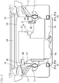
FIG. 2 is a sectional view cut along an II-II line ofFIG. 1 . -
FIG. 3 is a bottom view of the front portion of the vehicle from below. -
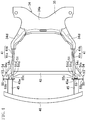
FIG. 4 is a plan view of a body portion and right and left front extension portions of a suspension cross member, right and left extension frames, a coupling cross member, crash cans, and a stiffener of the vehicle. -
FIG. 5 is a plan view of the left extension frame whose front end surface is fastened to the crash can, except for a fixing member. -
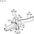
FIG. 6 is a perspective view of the left extension frame. -
FIG. 7 is an exploded perspective view of a configuration of a cutout portion of the left extension frame. -
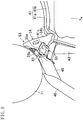
FIG. 8 is a schematic bottom view of a state of deformation of the left extension frame when small overlap collision with an obstacle occurs at a left portion of a front surface of the vehicle. -
FIG. 9 is a view corresponding toFIG. 8 when the obstacle further retreats relative to the vehicle fromFIG. 8 . - Hereinafter, an exemplary embodiment will be described in detail based on the drawings.
-
FIGS. 1 to 3 illustrate a main portion of a front portion of a vehicle 1 to which a vehicle body structure according to the exemplary embodiment is applied. In anengine room 2 at the front portion of the vehicle 1, apower train 5 configured to drive right and leftfront wheels 3 of the vehicle 1 is arranged. Thepower train 5 includes an engine 6 and atransmission 7 to which torque (power) generated by the engine 6 is input. Hereinafter, the front, rear, right, left, top, and bottom of the vehicle 1 will be each simply referred to as "front, rear, right, left, top, and bottom." - The engine 6 and the
transmission 7 are arranged in a vehicle width direction (a right-to-left direction) between right and leftfront side frames 11 in a pair as described above. In the present exemplary embodiment, the engine 6 is positioned at the right of thetransmission 7. A bottom end portion of the engine 6 includes anoil pan 6a (seeFIG. 3 ). - The right and left
front side frames 11 formed in a pair with a substantially rectangular closed sectional shape and extending in a vehicle longitudinal direction are each arranged at both end portions of theengine room 2 in the vehicle width direction. Moreover, a dash panel 13 (seeFIG. 2 ) separating theengine room 2 and avehicle compartment 12 is provided at a rear end portion of theengine room 2. Acowl member 14 is joined to a top end portion of thedash panel 13. Rear end portions of right and leftapron reinforcement members 19 extending in the vehicle longitudinal direction are each coupled to both end portions of thecowl member 14 in the vehicle width direction. -
Wheel house panels 17 and suspension towers 18 are each provided outside the right and left front side frames 11 in the vehicle width direction. Eachwheel house panel 17 is formed in an arc shape to cover the top side of thefront wheel 3, and a front wheel house is formed inside such an arc. Bottom end portions of the right and left suspension towers 18 are each fixed to the right and left front side frames 11, and top end portions of the right and left suspension towers 18 are each fixed to the right and leftapron reinforcement members 19. - The
power train 5 is elastically supported by the pair of right and left front side frames 11 through aright mount device 25 and aleft mount device 21 at both end portions of thepower train 5 such that a longitudinal direction of thepower train 5 is along the vehicle width direction. Theleft mount device 21 has a power trainside coupling member 22 coupled to a top portion of a left end portion of thetransmission 7, a vehicle bodyside coupling member 23 coupled to the leftfront side frame 11 and the leftwheel house panel 17, and a rubber bush (not shown) arranged between thesecoupling members left mount device 21, the top portion of the left end portion of thetransmission 7 is elastically supported by the leftfront side frame 11. Moreover, theright mount device 25 has a power trainside coupling member 26 coupled to a top portion of a right end portion of the engine 6, a vehicle bodyside coupling member 27 coupled to the rightfront side frame 11 and the rightwheel house panel 17, and a rubber bush (not shown) arranged between thesecoupling members right mount device 25, the top portion of the right end portion of the engine 6 is elastically supported by the rightfront side frame 11. -
Crash cans 31 are each provided on front end surfaces of the right and left front side frames 11, and front end surfaces of these right and leftcrash cans 31 are each fixed to both right and left end portions of bumper beams 32 extending in the vehicle width direction. - As illustrated in
FIGS. 3 and4 , asuspension cross member 34 extending in the vehicle width direction below the right and left front side frames 11 is arranged slightly at the rear side of the suspension towers 18. Thesuspension cross member 34 includes atop member 35 and abottom member 36 joined to each other at peripheral edge portions. - The
suspension cross member 34 has abody portion 34a extending in the vehicle width direction andfront extension portions 34b extending inclined outward in the vehicle width direction from front edges of both right and left end portions of thebody portion 34a toward the front side. The right and leftfront extension portions 34b are formed in a substantially rectangular closed sectional shape by thetop member 35 and thebottom member 36. - The right and left
front wheels 3 are supported by thebody portion 34a of thesuspension cross member 34 through right and left suspension arms 39 (lower arms) forming part of a front wheel suspension. The right and leftfront wheels 3 are each supported by one end portions (outer end portions in the vehicle width direction) of the right and leftsuspension arms 39, and the other end portions (inner end portions in the vehicle width direction) of the right and leftsuspension arms 39 are each supported at both right and left end portions of a rear portion of thebody portion 34a through rubber bushes by shafts 40 (seeFIG. 3 ) extending in a top-to-bottom direction. Although not shown in the figure, middle portions of thesuspension arms 39 in a longitudinal direction thereof are each supported at the right and leftfront extension portions 34b through rubber bushes by shafts extending in the vehicle longitudinal direction. - Top extension portions (not shown) extending upward are each provided on top surfaces of the right and left
front extension portions 34b, and top end portions of these right and left top extension portions are each fixed to bottom surfaces of the right and left front side frames 11. - In the vicinity of the center of the
body portion 34a of thesuspension cross member 34 in the vehicle width direction, a torquerod support portion 34c is provided to rotatably support, about an axis extending in the vehicle width direction, atorque rod 29 provided at a portion of a bottom surface of the engine 6 in the vicinity of thetransmission 7. By elastic supporting of thepower train 5 at both end portions thereof in the vehicle width direction by the right andleft mount devices power train 5 rotates (swings) about the axis extending in the vehicle width direction. However, thetorque rod 29 restricts excessive rotation of the entirety of thepower train 5 about the above-described axis. - Extension frames 41 formed in a substantially rectangular closed sectional shape and extending in the vehicle longitudinal direction at positions below the right and left front side frames 11 are linked to front end portions of the right and left
front extension portions 34b. Each of the right and left extension frames 41 includes anouter member 41a positioned outside in the vehicle width direction, and aninner member 41b positioned inside in the vehicle width direction. Theouter member 41a and theinner member 41b are in a substantially U-shaped sectional shape, and are welded and joined with openings of these U-shapes facing each other. The right and left extension frames 41 are at the substantially same position as that of the right and left front side frames 11 in the vehicle width direction. - A rear end portion of each
extension frame 41 is welded and joined to a corresponding one of thefront extension portions 34b (thetop member 35 and the bottom member 36) with the rear end portion being inserted into the closed section of the corresponding one of thefront extension portions 34b. That is, the rear end portion of eachextension frame 41 is welded and joined with the rear end portion overlapping with thesuspension cross member 34 in the vehicle longitudinal direction. - A crash can 45 similar to the crash can 31 provided at a front end of each
front side frame 11 is provided on a front end surface of eachextension frame 41. Aset plate 45a is provided on a rear end surface of each crash can 45, and is fastened and fixed to the front end surface of each extension frame 41 (specifically, anouter portion 55b and aninner portion 55c of a later-described front member 55) with multiple (three in the present exemplary embodiment) bolts 60 (illustrated only inFIGS. 5 and6 ). - The front end surfaces of the right and left
crash cans 45 are, at positions below the bumper beams 32, each fixed to both right and left end portions of astiffener 46 extending in the vehicle width direction. Thestiffener 46 is configured to contact bottom portions of the legs of a pedestrian colliding with a front surface of the vehicle 1 to sweep these legs, thereby causing the pedestrian to fall over a bonnet of the vehicle 1. This prevents occurrence of an injury of the legs of the pedestrian, such as bone fracture, as much as possible. Note that front portions of the bumper beams 32 and thestiffener 46 are covered with a not-shown front bumper. - As illustrated in
FIGS. 3 and5 , acutout portion 41c cut out rearwardly in a rectangular shape from the front end of eachextension frame 41 to leave two side portions as viewed in plane is formed at the front end surface of eachextension frame 41. Thecutout portion 41c is for weight reduction of theextension frame 41. - The front end portions of the right and left extension frames 41 are coupled to each other by a
coupling cross member 43 extending in the vehicle width direction. Thebody portion 34a and the right and leftfront extension portions 34b of thesuspension cross member 34, the right and left extension frames 41, and thecoupling cross member 43 form a perimeter frame in a substantially rectangular shape as viewed in plane. - At a portion extending from a front end of each
extension frame 41, aload receiving portion 53 expanded outward in the vehicle width direction from the front end of theextension frame 41 and configured to receive impact load upon front collision of the vehicle 1 outside theextension frame 41 in the vehicle width direction (i.e., outside thefront side frame 11 in the vehicle width direction) is provided. That is, when so-called small overlap collision occurs, i.e., a portion of the front surface (specifically, the front bumper) of the vehicle 1 outside theextension frame 41 in the vehicle width direction and an obstacle 71 (seeFIGS. 8 and9 ) collide with each other, such impact load is input to theload receiving portion 53. - As illustrated in
FIGS. 3 to 7 , theload receiving portion 53 of eachextension frame 41 includes a plate-shapedbody member 54 having a substantially U-shaped section cut at a plane along the vehicle width direction and bent such that an opening of the U-shape faces inward in the vehicle width direction, and part (the later-describedouter portion 55b) of thefront member 55 forming the front end surface of theextension frame 41. - The
body member 54 has atop portion 54a welded and joined to a top surface of theextension frame 41, and abottom portion 54b (seeFIG. 3 ) welded and joined to a bottom surface of theextension frame 41 with thebottom portion 54b facing thetop portion 54a. Thetop portion 54a and thebottom portion 54b are in a substantially triangular shape having the same size as viewed in plane, and have front edges extending straight outward in the vehicle width direction and rear edges extending inclined inward in the vehicle width direction from protruding tip ends of the front edges to the rear side. The rear edges of thetop portion 54a and thebottom portion 54b are coupled to each other by arear portion 54c formed integrally with thetop portion 54a and thebottom portion 54b. Thebody member 54 forms part of theextension frame 41. - The
front member 55 has acutout formation portion 55a forming both side portions of thecutout portion 41c in the vehicle width direction and a rear end portion of thecutout portion 41c and formed in a substantially U-shape as viewed in plane, and theouter portion 55b and theinner portion 55c each extending outward and inward from both end portions of the U-shapedcutout formation portion 55a in the vehicle width direction. That is, thefront member 55 is in a hat shape as viewed in plane. A front opening end (i.e., an opening end of the U-shapedcutout formation portion 55a) of thecutout portion 41c, theouter portion 55b, and theinner portion 55c are positioned closer to the front side with respect to thecoupling cross member 43. - The
outer portion 55b forms a front portion of theload receiving portion 53, and is welded and joined to a front end surface of the body member 54 (specifically, front edges of thetop portion 54a and thebottom portion 54b). Theinner portion 55c is welded and joined to a front end surface of theinner member 41b of theextension frame 41. Theset plate 45a of the crash can 45 is fastened to theouter portion 55b and theinner portion 55c with thebolts 60. Thecutout formation portion 55a is welded and joined to both of thebody member 54 and theinner member 41b. - The
cutout formation portion 55a extends upward of top surfaces of theouter member 41a and theinner member 41b of theextension frame 41, and a fixingmember 51 for fixing to thefront side frame 11 positioned above theextension frame 41 is provided at a top end of thecutout formation portion 55a. The fixingmember 51 has aplate material 51a welded and joined to the top end of thecutout formation portion 55a to close a top opening of thecutout portion 41c, and apin member 51b extending upward to allow insertion from theplate material 51a into thefront side frame 11 and fixed to a member provided inside thefront side frame 11. With this configuration, eachextension frame 41 is fixed to a corresponding one of the front side frames 11 through thefront member 55 and the fixingmember 51. - Each
extension frame 41 is curved to protrude inward in the vehicle width direction at the rear side of theload receiving portion 53. This is because theextension frame 41 is easily bent inward in the vehicle width direction when the impact load is input to theload receiving portion 53. - In the present exemplary embodiment, the
left extension frame 41 is equivalent to a frame included in the vehicle body structure of the present invention, and theright extension frame 41 is equivalent to an opposing frame extending in the vehicle longitudinal direction at the opposite side of thepower train 5 from theleft extension frame 41. Hereinafter, a configuration of theleft extension frame 41 and deformation of theleft extension frame 41 upon small overlap collision at a left portion of the front surface of the vehicle 1 will be described. - The
left extension frame 41 extends in the vehicle longitudinal direction outside (the left side) the power train 5 (the transmission 7) in the vehicle width direction. A casebottom end portion 7a of thetransmission 7 is at the same height position as that of the left extension frame 41 (seeFIG. 2 ). A clearance in the vehicle width direction between theleft extension frame 41 and the power train 5 (the casebottom end portion 7a) is smaller than a clearance in the vehicle width direction between theright extension frame 41 and the power train 5 (theoil pan 6a at the same height position as that of the right extension frame 41). - In the vicinity of the front opening end in the
cutout portion 41c of theleft extension frame 41, a plate-shapedconnection member 65 connecting both side portions of thecutout portion 41c in the vehicle width direction (two surfaces of thecutout formation portion 55a facing each other in the vehicle width direction) is provided. Both end portions of theconnection member 65 in the vehicle width direction are each welded and joined to both side portions of thecutout portion 41c in the vehicle width direction. As described later, theconnection member 65 is a member configured to reduce expansion of thecutout portion 41c in the vehicle width direction (i.e., an increase in an interval between the side portions of thecutout portion 41c in the vehicle width direction) when the impact load is input to theload receiving portion 53. Note that in the present exemplary embodiment, noconnection member 65 is provided at theright extension frame 41. - When small overlap collision with the
obstacle 71 occurs at the left portion of the front surface of the vehicle 1, the impact load is, from the front side, input to theload receiving portion 53 of theleft extension frame 41. Accordingly, pressing force for inward pressing in the vehicle width direction acts on a portion of theleft extension frame 41 provided with theload receiving portion 53. By such pressing force, theleft extension frame 41 is bent inward in the vehicle width direction. - Unlike the
right extension frame 41, theleft extension frame 41 has a smaller clearance from the power train 5 (the casebottom end portion 7a of the transmission 7) in the vehicle width direction. Thus, theleft extension frame 41 contacts the power train 5 (a front end portion of the casebottom end portion 7a) before being sufficiently bent. Consequently, as illustrated inFIG. 8 , in a state in which a portion of theleft extension frame 41 at the same position in the vehicle longitudinal direction as that of the front end portion of the casebottom end portion 7a contacts the casebottom end portion 7a, a portion of theleft extension frame 41 at the front side of the casebottom end portion 7a is pushed inward in the vehicle width direction by the pressing force. Thecoupling cross member 43 is curved to a certain extent by such pressing, but the portion of theleft extension frame 41 at the front side of the casebottom end portion 7a is not further pushed inward in the vehicle width direction by thecoupling cross member 43. - In this state, when the
obstacle 71 attempts to further retreat relative to the vehicle 1, a portion outside thecutout portion 41c in the vehicle width direction at the portion extending from the front end of theleft extension frame 41 to the vicinity thereof attempts, by the impact load input to theload receiving portion 53, to rotate backward about a base point, i.e., a contact portion of theleft extension frame 41 with thepower train 5 or a coupling portion of theleft extension frame 41 to thecoupling cross member 43. By such rotation, the portion outside thecutout portion 41c in the vehicle width direction at the portion extending from the front end of theleft extension frame 41 to the vicinity thereof is separated outward in the vehicle width direction and backward from a portion inside thecutout portion 41c in the vehicle width direction (i.e., thecutout portion 41c expands in the vehicle width direction). - Due to these reasons, if no
connection member 65 is provided inside thecutout portion 41c of theleft extension frame 41, thecutout portion 41c expands in the vehicle width direction, and therefore, it is difficult to transfer the impact load input to theload receiving portion 53 to theleft extension frame 41. - On the other hand, in the present exemplary embodiment, the
connection member 65 is provided inside thecutout portion 41c of theleft extension frame 41. Thus, as illustrated inFIG. 9 , even when theobstacle 71 further retreats relative to the vehicle 1, thecutout portion 41c does not greatly expand in the vehicle width direction. Thus, the impact load input to theload receiving portion 53 is, as the pressing force, efficiently transferred to theleft extension frame 41. The pressing force is transferred to theright extension frame 41 through thepower train 5. With this configuration, the impact load input to theload receiving portion 53 from the vehicle front side can be converted into load in the vehicle width direction. As a result, the orientation of the vehicle can be changed such that the front portion of the vehicle 1 moves to a side (the right side in the present exemplary embodiment) away from theobstacle 71 in the vehicle width direction. Consequently, transfer of the impact load upon small overlap collision of the vehicle 1 into the vehicle compartment of the vehicle 1 can be reduced. - The present invention is not limited to the above-described exemplary embodiment, and substitutions can be made without departing from the gist of the claims.
- For example, in the above-described exemplary embodiment, the
left extension frame 41 is the frame included in the vehicle body structure of the present invention. Instead of or in addition to theleft extension frame 41, theright extension frame 41 may be used as such a frame. In this case, both side portions of thecutout portion 41c of theright extension frame 41 in the vehicle width direction are connected to each other by theconnection member 65. - Moreover, the above-described frame is not limited to the
extension frame 41, and may be at least one of the right and left front side frames 11. In this case, the load receiving portion and the cutout portion are, as in theextension frame 41, provided at at least one of the right and left front side frames 11, and both side portions of the cutout portion in the vehicle width direction are connected to each other by the connection member. - The above-described exemplary embodiment has been set forth merely as an example, and the scope of the present invention shall not be interpreted in a limited manner. The scope of the present invention is defined instead only by the appended claims.
Claims (5)
- A vehicle body structure comprising:a frame (41) extending in a vehicle longitudinal direction outside a power train (5) in a vehicle width direction, the power train (5) being mounted on a front portion of a vehicle (1),a load receiving portion (53) expanding outward in the vehicle width direction from a front end of the frame and configured to receive impact load acting upon front collision of the vehicle (1) outside the frame (41) in the vehicle width direction,a cutout portion (41c) provided at the front end of the frame (41), whereinthe frame (41) is, through a coupling cross member (43) extending in the vehicle width direction, coupled to an opposing frame (41) extending in the vehicle longitudinal direction at an opposite side of the power train (5) from the frame (41), anda vehicle-front-side opening end of the cutout portion (41c) is positioned closer to a vehicle front side with respect to the coupling cross member (43),a front member (55) is provided to a front end face of the frame (41),the front member (55) includes a cutout formation portion (55a) forming the cutout portion (41c), characterized in that, the cutout portion (41c) is cut out rearwardly from the front end of the frame (41) to leave two side portions, and the vehicle body structure comprising:a connection member (65) connecting the side portions of the cutout portion (41c) in the vehicle width direction, whereinthe frame (41) is curved to protrude inward in the vehicle width direction at the vehicle rear side of the load receiving portion (53), whereinthe connection member (65) connects two surfaces of the cutout formation portion (55a) facing each other in the vehicle width direction, the two surfaces being the two side portions.
- The vehicle body structure according to claim 1, wherein said cutout portion (41c) is U-shaped when viewing the frame (41) in a plane view, wherein one of said two side portions left by the cutout is formed by the frame (41) and a second one of said two side portions is formed by said load receiving portion (53).
- The vehicle body structure according to claim 1 or 2, wherein said cutout formation portion (55a) of said front member (55) is formed in a U-shape as viewed in plane, extends upward of top surfaces of inner and outer members (41a, 41b) of said frame (41) and forms both side portions of the cutout portion (41c) in the vehicle width direction and a rear end portion of the cutout portion (41c), wherein the front member (55) further includes an outer portion (55b) extending outward from an end portion of said U-shaped cutout formation portion (55a) in the vehicle width direction and an inner portion (55c) extending inward from a second one of said end portions of the U-shaped cutout formation portion (55a) in the vehicle width direction, wherein said outer portion (55b) forms a front portion of the load receiving portion (53) and said inner portion (55c) is joint to a front end surface of an inner member (41b) of the frame (41).
- The vehicle body structure according to claim 1, wherein
a set plate (45a) provided at a vehicle-rear-side end surface of a crash can (45) is, with a bolt (60), fastened to the vehicle-front-side end surface of the frame (41), and
the connection member (65) is welded and joined to both side portions of the cutout portion (41c) in the vehicle width direction. - The vehicle body structure according to claim 1 or 4, wherein
the connection member (65) is provided in a vicinity of the vehicle-front-side opening end of the cutout portion (41c).
Applications Claiming Priority (1)
| Application Number | Priority Date | Filing Date | Title |
|---|---|---|---|
| JP2017196502A JP6996707B2 (en) | 2017-10-10 | 2017-10-10 | Body structure |
Publications (2)
| Publication Number | Publication Date |
|---|---|
| EP3470306A1 EP3470306A1 (en) | 2019-04-17 |
| EP3470306B1 true EP3470306B1 (en) | 2020-12-16 |
Family
ID=63787813
Family Applications (1)
| Application Number | Title | Priority Date | Filing Date |
|---|---|---|---|
| EP18198853.6A Active EP3470306B1 (en) | 2017-10-10 | 2018-10-05 | Vehicle body structure |
Country Status (4)
| Country | Link |
|---|---|
| US (1) | US10703313B2 (en) |
| EP (1) | EP3470306B1 (en) |
| JP (1) | JP6996707B2 (en) |
| CN (1) | CN109649501B (en) |
Families Citing this family (6)
| Publication number | Priority date | Publication date | Assignee | Title |
|---|---|---|---|---|
| JP6597649B2 (en) * | 2017-01-13 | 2019-10-30 | トヨタ自動車株式会社 | Body frame structure |
| US10550927B2 (en) * | 2017-11-20 | 2020-02-04 | Ford Global Technologies, Llc | Multi-function transmission crossmember |
| DE102018000065A1 (en) * | 2018-01-08 | 2019-07-11 | Daimler Ag | Body structure and bodywork for a passenger car |
| US11505251B2 (en) * | 2020-06-25 | 2022-11-22 | Rivian Ip Holdings, Llc | Vehicle structure for managing lateral loads in front crash events |
| US11292523B2 (en) * | 2020-06-25 | 2022-04-05 | Rivian Ip Holdings, Llc | Vehicle structure for managing lateral loads in front crash events |
| KR20230096453A (en) * | 2021-12-23 | 2023-06-30 | 현대자동차주식회사 | Mounting structure of sub-frame of vehicle for avoiding collision between battery and sub-frame |
Family Cites Families (15)
| Publication number | Priority date | Publication date | Assignee | Title |
|---|---|---|---|---|
| JPS5889475A (en) * | 1981-11-20 | 1983-05-27 | Toyota Motor Corp | Back and front direction reinforcing member for car |
| JP5357953B2 (en) * | 2011-04-01 | 2013-12-04 | 本田技研工業株式会社 | Body front structure |
| JP5287927B2 (en) * | 2011-05-13 | 2013-09-11 | トヨタ自動車株式会社 | Body structure |
| JP5949939B2 (en) * | 2012-11-16 | 2016-07-13 | 日産自動車株式会社 | Body front structure |
| DE102013208144A1 (en) * | 2013-05-03 | 2014-11-06 | Bayerische Motoren Werke Aktiengesellschaft | Automotive body |
| JP6052230B2 (en) * | 2014-05-21 | 2016-12-27 | マツダ株式会社 | Vehicle body structure |
| JP6420066B2 (en) * | 2014-06-10 | 2018-11-07 | 株式会社ワイテック | Front subframe |
| JP2016037242A (en) * | 2014-08-08 | 2016-03-22 | トヨタ自動車株式会社 | Vehicle front structure |
| JP6139501B2 (en) * | 2014-12-25 | 2017-05-31 | 本田技研工業株式会社 | Body front structure |
| JP6131967B2 (en) * | 2015-02-02 | 2017-05-24 | マツダ株式会社 | Auto body structure |
| JP6052310B2 (en) * | 2015-02-03 | 2016-12-27 | マツダ株式会社 | Auto body structure |
| CN106476893A (en) * | 2015-08-27 | 2017-03-08 | 北京长城华冠汽车科技股份有限公司 | The front housing assembly of automobile and its automobile |
| JP6546065B2 (en) * | 2015-10-26 | 2019-07-17 | 本田技研工業株式会社 | Front body structure |
| CN205589309U (en) * | 2016-03-23 | 2016-09-21 | 上汽通用汽车有限公司 | Sub vehicle puts up longeron |
| JP6923876B2 (en) * | 2017-03-28 | 2021-08-25 | 株式会社ワイテック | Front body structure of the car |
-
2017
- 2017-10-10 JP JP2017196502A patent/JP6996707B2/en active Active
-
2018
- 2018-10-05 EP EP18198853.6A patent/EP3470306B1/en active Active
- 2018-10-08 US US16/154,396 patent/US10703313B2/en active Active
- 2018-10-08 CN CN201811166329.XA patent/CN109649501B/en active Active
Non-Patent Citations (1)
| Title |
|---|
| None * |
Also Published As
| Publication number | Publication date |
|---|---|
| EP3470306A1 (en) | 2019-04-17 |
| JP6996707B2 (en) | 2022-01-17 |
| CN109649501A (en) | 2019-04-19 |
| US10703313B2 (en) | 2020-07-07 |
| US20190106072A1 (en) | 2019-04-11 |
| JP2019069682A (en) | 2019-05-09 |
| CN109649501B (en) | 2021-08-31 |
Similar Documents
| Publication | Publication Date | Title |
|---|---|---|
| US10703313B2 (en) | Vehicle body structure | |
| US6209948B1 (en) | Front structure of car body, and method of absorbing impact by means of the front structure | |
| US9855971B2 (en) | Vehicle body structure with impact absorbing part | |
| US9868472B2 (en) | Bonnet structure of automotive vehicle | |
| EP0990577B1 (en) | Front body structure of vehicle | |
| JP3681945B2 (en) | Bumper reinforcement with shock absorbing mechanism | |
| JP6471782B1 (en) | Body structure | |
| JP7449155B2 (en) | Front body structure | |
| JPWO1997029005A1 (en) | Front body structure and impact absorption method using front body structure | |
| JP2008074349A (en) | Vehicle front structure | |
| JP5513903B2 (en) | Shock absorber for vehicle | |
| JP2004532770A (en) | Automobile body with flexible mounted hood | |
| JP5228014B2 (en) | Body front structure | |
| JP2005022598A (en) | Bumper equipment | |
| CN109070941B (en) | Front fender structure of motor vehicle | |
| JP2022012130A (en) | Front vehicle body structure for vehicle | |
| JP2019038311A (en) | Body structure | |
| JP4687033B2 (en) | Body front structure | |
| JP4798485B2 (en) | Vehicle front bumper structure | |
| JP4867509B2 (en) | Subframe structure | |
| JP7697478B2 (en) | Chassis frame structure | |
| JP7518479B2 (en) | Chassis frame structure | |
| JP2020040548A (en) | Body front structure | |
| EP2428432B1 (en) | Front side vehicle body structure | |
| WO2025182801A1 (en) | Vehicle body end part structure |
Legal Events
| Date | Code | Title | Description |
|---|---|---|---|
| PUAI | Public reference made under article 153(3) epc to a published international application that has entered the european phase |
Free format text: ORIGINAL CODE: 0009012 |
|
| STAA | Information on the status of an ep patent application or granted ep patent |
Free format text: STATUS: THE APPLICATION HAS BEEN PUBLISHED |
|
| AK | Designated contracting states |
Kind code of ref document: A1 Designated state(s): AL AT BE BG CH CY CZ DE DK EE ES FI FR GB GR HR HU IE IS IT LI LT LU LV MC MK MT NL NO PL PT RO RS SE SI SK SM TR |
|
| AX | Request for extension of the european patent |
Extension state: BA ME |
|
| STAA | Information on the status of an ep patent application or granted ep patent |
Free format text: STATUS: REQUEST FOR EXAMINATION WAS MADE |
|
| 17P | Request for examination filed |
Effective date: 20191014 |
|
| RBV | Designated contracting states (corrected) |
Designated state(s): AL AT BE BG CH CY CZ DE DK EE ES FI FR GB GR HR HU IE IS IT LI LT LU LV MC MK MT NL NO PL PT RO RS SE SI SK SM TR |
|
| GRAP | Despatch of communication of intention to grant a patent |
Free format text: ORIGINAL CODE: EPIDOSNIGR1 |
|
| STAA | Information on the status of an ep patent application or granted ep patent |
Free format text: STATUS: GRANT OF PATENT IS INTENDED |
|
| INTG | Intention to grant announced |
Effective date: 20200706 |
|
| GRAS | Grant fee paid |
Free format text: ORIGINAL CODE: EPIDOSNIGR3 |
|
| GRAA | (expected) grant |
Free format text: ORIGINAL CODE: 0009210 |
|
| STAA | Information on the status of an ep patent application or granted ep patent |
Free format text: STATUS: THE PATENT HAS BEEN GRANTED |
|
| AK | Designated contracting states |
Kind code of ref document: B1 Designated state(s): AL AT BE BG CH CY CZ DE DK EE ES FI FR GB GR HR HU IE IS IT LI LT LU LV MC MK MT NL NO PL PT RO RS SE SI SK SM TR |
|
| REG | Reference to a national code |
Ref country code: GB Ref legal event code: FG4D |
|
| REG | Reference to a national code |
Ref country code: IE Ref legal event code: FG4D |
|
| REG | Reference to a national code |
Ref country code: DE Ref legal event code: R096 Ref document number: 602018010827 Country of ref document: DE |
|
| REG | Reference to a national code |
Ref country code: AT Ref legal event code: REF Ref document number: 1345345 Country of ref document: AT Kind code of ref document: T Effective date: 20210115 |
|
| PG25 | Lapsed in a contracting state [announced via postgrant information from national office to epo] |
Ref country code: GR Free format text: LAPSE BECAUSE OF FAILURE TO SUBMIT A TRANSLATION OF THE DESCRIPTION OR TO PAY THE FEE WITHIN THE PRESCRIBED TIME-LIMIT Effective date: 20210317 Ref country code: NO Free format text: LAPSE BECAUSE OF FAILURE TO SUBMIT A TRANSLATION OF THE DESCRIPTION OR TO PAY THE FEE WITHIN THE PRESCRIBED TIME-LIMIT Effective date: 20210316 Ref country code: FI Free format text: LAPSE BECAUSE OF FAILURE TO SUBMIT A TRANSLATION OF THE DESCRIPTION OR TO PAY THE FEE WITHIN THE PRESCRIBED TIME-LIMIT Effective date: 20201216 Ref country code: RS Free format text: LAPSE BECAUSE OF FAILURE TO SUBMIT A TRANSLATION OF THE DESCRIPTION OR TO PAY THE FEE WITHIN THE PRESCRIBED TIME-LIMIT Effective date: 20201216 |
|
| REG | Reference to a national code |
Ref country code: AT Ref legal event code: MK05 Ref document number: 1345345 Country of ref document: AT Kind code of ref document: T Effective date: 20201216 |
|
| REG | Reference to a national code |
Ref country code: NL Ref legal event code: MP Effective date: 20201216 |
|
| PG25 | Lapsed in a contracting state [announced via postgrant information from national office to epo] |
Ref country code: BG Free format text: LAPSE BECAUSE OF FAILURE TO SUBMIT A TRANSLATION OF THE DESCRIPTION OR TO PAY THE FEE WITHIN THE PRESCRIBED TIME-LIMIT Effective date: 20210316 Ref country code: LV Free format text: LAPSE BECAUSE OF FAILURE TO SUBMIT A TRANSLATION OF THE DESCRIPTION OR TO PAY THE FEE WITHIN THE PRESCRIBED TIME-LIMIT Effective date: 20201216 Ref country code: SE Free format text: LAPSE BECAUSE OF FAILURE TO SUBMIT A TRANSLATION OF THE DESCRIPTION OR TO PAY THE FEE WITHIN THE PRESCRIBED TIME-LIMIT Effective date: 20201216 |
|
| PG25 | Lapsed in a contracting state [announced via postgrant information from national office to epo] |
Ref country code: HR Free format text: LAPSE BECAUSE OF FAILURE TO SUBMIT A TRANSLATION OF THE DESCRIPTION OR TO PAY THE FEE WITHIN THE PRESCRIBED TIME-LIMIT Effective date: 20201216 Ref country code: NL Free format text: LAPSE BECAUSE OF FAILURE TO SUBMIT A TRANSLATION OF THE DESCRIPTION OR TO PAY THE FEE WITHIN THE PRESCRIBED TIME-LIMIT Effective date: 20201216 |
|
| REG | Reference to a national code |
Ref country code: LT Ref legal event code: MG9D |
|
| PG25 | Lapsed in a contracting state [announced via postgrant information from national office to epo] |
Ref country code: PT Free format text: LAPSE BECAUSE OF FAILURE TO SUBMIT A TRANSLATION OF THE DESCRIPTION OR TO PAY THE FEE WITHIN THE PRESCRIBED TIME-LIMIT Effective date: 20210416 Ref country code: SK Free format text: LAPSE BECAUSE OF FAILURE TO SUBMIT A TRANSLATION OF THE DESCRIPTION OR TO PAY THE FEE WITHIN THE PRESCRIBED TIME-LIMIT Effective date: 20201216 Ref country code: RO Free format text: LAPSE BECAUSE OF FAILURE TO SUBMIT A TRANSLATION OF THE DESCRIPTION OR TO PAY THE FEE WITHIN THE PRESCRIBED TIME-LIMIT Effective date: 20201216 Ref country code: LT Free format text: LAPSE BECAUSE OF FAILURE TO SUBMIT A TRANSLATION OF THE DESCRIPTION OR TO PAY THE FEE WITHIN THE PRESCRIBED TIME-LIMIT Effective date: 20201216 Ref country code: EE Free format text: LAPSE BECAUSE OF FAILURE TO SUBMIT A TRANSLATION OF THE DESCRIPTION OR TO PAY THE FEE WITHIN THE PRESCRIBED TIME-LIMIT Effective date: 20201216 Ref country code: CZ Free format text: LAPSE BECAUSE OF FAILURE TO SUBMIT A TRANSLATION OF THE DESCRIPTION OR TO PAY THE FEE WITHIN THE PRESCRIBED TIME-LIMIT Effective date: 20201216 Ref country code: SM Free format text: LAPSE BECAUSE OF FAILURE TO SUBMIT A TRANSLATION OF THE DESCRIPTION OR TO PAY THE FEE WITHIN THE PRESCRIBED TIME-LIMIT Effective date: 20201216 |
|
| PG25 | Lapsed in a contracting state [announced via postgrant information from national office to epo] |
Ref country code: PL Free format text: LAPSE BECAUSE OF FAILURE TO SUBMIT A TRANSLATION OF THE DESCRIPTION OR TO PAY THE FEE WITHIN THE PRESCRIBED TIME-LIMIT Effective date: 20201216 Ref country code: AT Free format text: LAPSE BECAUSE OF FAILURE TO SUBMIT A TRANSLATION OF THE DESCRIPTION OR TO PAY THE FEE WITHIN THE PRESCRIBED TIME-LIMIT Effective date: 20201216 |
|
| REG | Reference to a national code |
Ref country code: DE Ref legal event code: R097 Ref document number: 602018010827 Country of ref document: DE |
|
| PG25 | Lapsed in a contracting state [announced via postgrant information from national office to epo] |
Ref country code: IS Free format text: LAPSE BECAUSE OF FAILURE TO SUBMIT A TRANSLATION OF THE DESCRIPTION OR TO PAY THE FEE WITHIN THE PRESCRIBED TIME-LIMIT Effective date: 20210416 |
|
| PLBE | No opposition filed within time limit |
Free format text: ORIGINAL CODE: 0009261 |
|
| STAA | Information on the status of an ep patent application or granted ep patent |
Free format text: STATUS: NO OPPOSITION FILED WITHIN TIME LIMIT |
|
| PG25 | Lapsed in a contracting state [announced via postgrant information from national office to epo] |
Ref country code: IT Free format text: LAPSE BECAUSE OF FAILURE TO SUBMIT A TRANSLATION OF THE DESCRIPTION OR TO PAY THE FEE WITHIN THE PRESCRIBED TIME-LIMIT Effective date: 20201216 Ref country code: AL Free format text: LAPSE BECAUSE OF FAILURE TO SUBMIT A TRANSLATION OF THE DESCRIPTION OR TO PAY THE FEE WITHIN THE PRESCRIBED TIME-LIMIT Effective date: 20201216 |
|
| 26N | No opposition filed |
Effective date: 20210917 |
|
| PG25 | Lapsed in a contracting state [announced via postgrant information from national office to epo] |
Ref country code: DK Free format text: LAPSE BECAUSE OF FAILURE TO SUBMIT A TRANSLATION OF THE DESCRIPTION OR TO PAY THE FEE WITHIN THE PRESCRIBED TIME-LIMIT Effective date: 20201216 |
|
| PG25 | Lapsed in a contracting state [announced via postgrant information from national office to epo] |
Ref country code: ES Free format text: LAPSE BECAUSE OF FAILURE TO SUBMIT A TRANSLATION OF THE DESCRIPTION OR TO PAY THE FEE WITHIN THE PRESCRIBED TIME-LIMIT Effective date: 20201216 |
|
| PG25 | Lapsed in a contracting state [announced via postgrant information from national office to epo] |
Ref country code: SI Free format text: LAPSE BECAUSE OF FAILURE TO SUBMIT A TRANSLATION OF THE DESCRIPTION OR TO PAY THE FEE WITHIN THE PRESCRIBED TIME-LIMIT Effective date: 20201216 |
|
| REG | Reference to a national code |
Ref country code: CH Ref legal event code: PL |
|
| PG25 | Lapsed in a contracting state [announced via postgrant information from national office to epo] |
Ref country code: IS Free format text: LAPSE BECAUSE OF FAILURE TO SUBMIT A TRANSLATION OF THE DESCRIPTION OR TO PAY THE FEE WITHIN THE PRESCRIBED TIME-LIMIT Effective date: 20210416 |
|
| REG | Reference to a national code |
Ref country code: BE Ref legal event code: MM Effective date: 20211031 |
|
| PG25 | Lapsed in a contracting state [announced via postgrant information from national office to epo] |
Ref country code: MC Free format text: LAPSE BECAUSE OF FAILURE TO SUBMIT A TRANSLATION OF THE DESCRIPTION OR TO PAY THE FEE WITHIN THE PRESCRIBED TIME-LIMIT Effective date: 20201216 |
|
| PG25 | Lapsed in a contracting state [announced via postgrant information from national office to epo] |
Ref country code: LU Free format text: LAPSE BECAUSE OF NON-PAYMENT OF DUE FEES Effective date: 20211005 Ref country code: BE Free format text: LAPSE BECAUSE OF NON-PAYMENT OF DUE FEES Effective date: 20211031 |
|
| PG25 | Lapsed in a contracting state [announced via postgrant information from national office to epo] |
Ref country code: LI Free format text: LAPSE BECAUSE OF NON-PAYMENT OF DUE FEES Effective date: 20211031 Ref country code: CH Free format text: LAPSE BECAUSE OF NON-PAYMENT OF DUE FEES Effective date: 20211031 |
|
| PG25 | Lapsed in a contracting state [announced via postgrant information from national office to epo] |
Ref country code: FR Free format text: LAPSE BECAUSE OF NON-PAYMENT OF DUE FEES Effective date: 20211031 |
|
| PG25 | Lapsed in a contracting state [announced via postgrant information from national office to epo] |
Ref country code: IE Free format text: LAPSE BECAUSE OF NON-PAYMENT OF DUE FEES Effective date: 20211005 |
|
| GBPC | Gb: european patent ceased through non-payment of renewal fee |
Effective date: 20221005 |
|
| PG25 | Lapsed in a contracting state [announced via postgrant information from national office to epo] |
Ref country code: CY Free format text: LAPSE BECAUSE OF FAILURE TO SUBMIT A TRANSLATION OF THE DESCRIPTION OR TO PAY THE FEE WITHIN THE PRESCRIBED TIME-LIMIT Effective date: 20201216 |
|
| PG25 | Lapsed in a contracting state [announced via postgrant information from national office to epo] |
Ref country code: HU Free format text: LAPSE BECAUSE OF FAILURE TO SUBMIT A TRANSLATION OF THE DESCRIPTION OR TO PAY THE FEE WITHIN THE PRESCRIBED TIME-LIMIT; INVALID AB INITIO Effective date: 20181005 |
|
| PG25 | Lapsed in a contracting state [announced via postgrant information from national office to epo] |
Ref country code: GB Free format text: LAPSE BECAUSE OF NON-PAYMENT OF DUE FEES Effective date: 20221005 |
|
| PG25 | Lapsed in a contracting state [announced via postgrant information from national office to epo] |
Ref country code: MK Free format text: LAPSE BECAUSE OF FAILURE TO SUBMIT A TRANSLATION OF THE DESCRIPTION OR TO PAY THE FEE WITHIN THE PRESCRIBED TIME-LIMIT Effective date: 20201216 |
|
| PG25 | Lapsed in a contracting state [announced via postgrant information from national office to epo] |
Ref country code: MT Free format text: LAPSE BECAUSE OF FAILURE TO SUBMIT A TRANSLATION OF THE DESCRIPTION OR TO PAY THE FEE WITHIN THE PRESCRIBED TIME-LIMIT Effective date: 20201216 |
|
| PG25 | Lapsed in a contracting state [announced via postgrant information from national office to epo] |
Ref country code: TR Free format text: LAPSE BECAUSE OF FAILURE TO SUBMIT A TRANSLATION OF THE DESCRIPTION OR TO PAY THE FEE WITHIN THE PRESCRIBED TIME-LIMIT Effective date: 20201216 |
|
| PGFP | Annual fee paid to national office [announced via postgrant information from national office to epo] |
Ref country code: DE Payment date: 20250902 Year of fee payment: 8 |