EP3470196B1 - Device and method for the impregnation of fibre bundles with a polymer melt - Google Patents
Device and method for the impregnation of fibre bundles with a polymer melt Download PDFInfo
- Publication number
- EP3470196B1 EP3470196B1 EP17196681.5A EP17196681A EP3470196B1 EP 3470196 B1 EP3470196 B1 EP 3470196B1 EP 17196681 A EP17196681 A EP 17196681A EP 3470196 B1 EP3470196 B1 EP 3470196B1
- Authority
- EP
- European Patent Office
- Prior art keywords
- fiber bundles
- polymer melt
- guide plates
- sub
- impregnation unit
- Prior art date
- Legal status (The legal status is an assumption and is not a legal conclusion. Google has not performed a legal analysis and makes no representation as to the accuracy of the status listed.)
- Active
Links
- 239000000835 fiber Substances 0.000 title claims description 80
- 229920000642 polymer Polymers 0.000 title claims description 62
- 238000005470 impregnation Methods 0.000 title claims description 51
- 238000000034 method Methods 0.000 title claims description 13
- 239000000155 melt Substances 0.000 claims description 13
- 239000000463 material Substances 0.000 claims description 7
- 229920006395 saturated elastomer Polymers 0.000 claims description 6
- 230000000295 complement effect Effects 0.000 claims description 4
- 230000001105 regulatory effect Effects 0.000 claims description 2
- 230000007704 transition Effects 0.000 claims 1
- 239000004033 plastic Substances 0.000 description 11
- 229920003023 plastic Polymers 0.000 description 11
- 239000008187 granular material Substances 0.000 description 7
- 238000009826 distribution Methods 0.000 description 6
- 239000002657 fibrous material Substances 0.000 description 6
- 230000035515 penetration Effects 0.000 description 6
- 108010001267 Protein Subunits Proteins 0.000 description 5
- 238000004519 manufacturing process Methods 0.000 description 5
- 229920000426 Microplastic Polymers 0.000 description 3
- 239000002131 composite material Substances 0.000 description 3
- XLYOFNOQVPJJNP-UHFFFAOYSA-N water Substances O XLYOFNOQVPJJNP-UHFFFAOYSA-N 0.000 description 3
- OKTJSMMVPCPJKN-UHFFFAOYSA-N Carbon Chemical compound [C] OKTJSMMVPCPJKN-UHFFFAOYSA-N 0.000 description 2
- 239000004566 building material Substances 0.000 description 2
- 229910052799 carbon Inorganic materials 0.000 description 2
- 238000010276 construction Methods 0.000 description 2
- 239000011521 glass Substances 0.000 description 2
- 238000010438 heat treatment Methods 0.000 description 2
- 239000008188 pellet Substances 0.000 description 2
- 239000002861 polymer material Substances 0.000 description 2
- 229920001169 thermoplastic Polymers 0.000 description 2
- 229920000049 Carbon (fiber) Polymers 0.000 description 1
- 241000792859 Enema Species 0.000 description 1
- 229920002430 Fibre-reinforced plastic Polymers 0.000 description 1
- 239000004760 aramid Substances 0.000 description 1
- 229920003235 aromatic polyamide Polymers 0.000 description 1
- 230000001174 ascending effect Effects 0.000 description 1
- 230000015572 biosynthetic process Effects 0.000 description 1
- 239000004917 carbon fiber Substances 0.000 description 1
- 239000012141 concentrate Substances 0.000 description 1
- 238000009749 continuous casting Methods 0.000 description 1
- 238000011161 development Methods 0.000 description 1
- 230000018109 developmental process Effects 0.000 description 1
- 239000007920 enema Substances 0.000 description 1
- 229940095399 enema Drugs 0.000 description 1
- 238000001125 extrusion Methods 0.000 description 1
- 239000011151 fibre-reinforced plastic Substances 0.000 description 1
- -1 fine wires Substances 0.000 description 1
- 239000003365 glass fiber Substances 0.000 description 1
- 238000001746 injection moulding Methods 0.000 description 1
- 239000002952 polymeric resin Substances 0.000 description 1
- 239000002994 raw material Substances 0.000 description 1
- 230000000630 rising effect Effects 0.000 description 1
- 229920003002 synthetic resin Polymers 0.000 description 1
- 239000004753 textile Substances 0.000 description 1
Images


Classifications
-
- B—PERFORMING OPERATIONS; TRANSPORTING
- B29—WORKING OF PLASTICS; WORKING OF SUBSTANCES IN A PLASTIC STATE IN GENERAL
- B29B—PREPARATION OR PRETREATMENT OF THE MATERIAL TO BE SHAPED; MAKING GRANULES OR PREFORMS; RECOVERY OF PLASTICS OR OTHER CONSTITUENTS OF WASTE MATERIAL CONTAINING PLASTICS
- B29B15/00—Pretreatment of the material to be shaped, not covered by groups B29B7/00 - B29B13/00
- B29B15/08—Pretreatment of the material to be shaped, not covered by groups B29B7/00 - B29B13/00 of reinforcements or fillers
- B29B15/10—Coating or impregnating independently of the moulding or shaping step
- B29B15/12—Coating or impregnating independently of the moulding or shaping step of reinforcements of indefinite length
- B29B15/122—Coating or impregnating independently of the moulding or shaping step of reinforcements of indefinite length with a matrix in liquid form, e.g. as melt, solution or latex
-
- B—PERFORMING OPERATIONS; TRANSPORTING
- B29—WORKING OF PLASTICS; WORKING OF SUBSTANCES IN A PLASTIC STATE IN GENERAL
- B29C—SHAPING OR JOINING OF PLASTICS; SHAPING OF MATERIAL IN A PLASTIC STATE, NOT OTHERWISE PROVIDED FOR; AFTER-TREATMENT OF THE SHAPED PRODUCTS, e.g. REPAIRING
- B29C48/00—Extrusion moulding, i.e. expressing the moulding material through a die or nozzle which imparts the desired form; Apparatus therefor
- B29C48/025—General arrangement or layout of plant
- B29C48/0255—General arrangement or layout of plant for extruding parallel streams of material, e.g. several separate parallel streams of extruded material forming separate articles
-
- B—PERFORMING OPERATIONS; TRANSPORTING
- B29—WORKING OF PLASTICS; WORKING OF SUBSTANCES IN A PLASTIC STATE IN GENERAL
- B29C—SHAPING OR JOINING OF PLASTICS; SHAPING OF MATERIAL IN A PLASTIC STATE, NOT OTHERWISE PROVIDED FOR; AFTER-TREATMENT OF THE SHAPED PRODUCTS, e.g. REPAIRING
- B29C48/00—Extrusion moulding, i.e. expressing the moulding material through a die or nozzle which imparts the desired form; Apparatus therefor
- B29C48/03—Extrusion moulding, i.e. expressing the moulding material through a die or nozzle which imparts the desired form; Apparatus therefor characterised by the shape of the extruded material at extrusion
- B29C48/05—Filamentary, e.g. strands
-
- B—PERFORMING OPERATIONS; TRANSPORTING
- B29—WORKING OF PLASTICS; WORKING OF SUBSTANCES IN A PLASTIC STATE IN GENERAL
- B29C—SHAPING OR JOINING OF PLASTICS; SHAPING OF MATERIAL IN A PLASTIC STATE, NOT OTHERWISE PROVIDED FOR; AFTER-TREATMENT OF THE SHAPED PRODUCTS, e.g. REPAIRING
- B29C48/00—Extrusion moulding, i.e. expressing the moulding material through a die or nozzle which imparts the desired form; Apparatus therefor
- B29C48/15—Extrusion moulding, i.e. expressing the moulding material through a die or nozzle which imparts the desired form; Apparatus therefor incorporating preformed parts or layers, e.g. extrusion moulding around inserts
-
- B—PERFORMING OPERATIONS; TRANSPORTING
- B29—WORKING OF PLASTICS; WORKING OF SUBSTANCES IN A PLASTIC STATE IN GENERAL
- B29C—SHAPING OR JOINING OF PLASTICS; SHAPING OF MATERIAL IN A PLASTIC STATE, NOT OTHERWISE PROVIDED FOR; AFTER-TREATMENT OF THE SHAPED PRODUCTS, e.g. REPAIRING
- B29C48/00—Extrusion moulding, i.e. expressing the moulding material through a die or nozzle which imparts the desired form; Apparatus therefor
- B29C48/25—Component parts, details or accessories; Auxiliary operations
- B29C48/92—Measuring, controlling or regulating
-
- B—PERFORMING OPERATIONS; TRANSPORTING
- B29—WORKING OF PLASTICS; WORKING OF SUBSTANCES IN A PLASTIC STATE IN GENERAL
- B29C—SHAPING OR JOINING OF PLASTICS; SHAPING OF MATERIAL IN A PLASTIC STATE, NOT OTHERWISE PROVIDED FOR; AFTER-TREATMENT OF THE SHAPED PRODUCTS, e.g. REPAIRING
- B29C70/00—Shaping composites, i.e. plastics material comprising reinforcements, fillers or preformed parts, e.g. inserts
- B29C70/04—Shaping composites, i.e. plastics material comprising reinforcements, fillers or preformed parts, e.g. inserts comprising reinforcements only, e.g. self-reinforcing plastics
- B29C70/28—Shaping operations therefor
- B29C70/40—Shaping or impregnating by compression not applied
- B29C70/50—Shaping or impregnating by compression not applied for producing articles of indefinite length, e.g. prepregs, sheet moulding compounds [SMC] or cross moulding compounds [XMC]
- B29C70/52—Pultrusion, i.e. forming and compressing by continuously pulling through a die
- B29C70/523—Pultrusion, i.e. forming and compressing by continuously pulling through a die and impregnating the reinforcement in the die
-
- B—PERFORMING OPERATIONS; TRANSPORTING
- B29—WORKING OF PLASTICS; WORKING OF SUBSTANCES IN A PLASTIC STATE IN GENERAL
- B29C—SHAPING OR JOINING OF PLASTICS; SHAPING OF MATERIAL IN A PLASTIC STATE, NOT OTHERWISE PROVIDED FOR; AFTER-TREATMENT OF THE SHAPED PRODUCTS, e.g. REPAIRING
- B29C70/00—Shaping composites, i.e. plastics material comprising reinforcements, fillers or preformed parts, e.g. inserts
- B29C70/04—Shaping composites, i.e. plastics material comprising reinforcements, fillers or preformed parts, e.g. inserts comprising reinforcements only, e.g. self-reinforcing plastics
- B29C70/28—Shaping operations therefor
- B29C70/54—Component parts, details or accessories; Auxiliary operations, e.g. feeding or storage of prepregs or SMC after impregnation or during ageing
-
- B—PERFORMING OPERATIONS; TRANSPORTING
- B29—WORKING OF PLASTICS; WORKING OF SUBSTANCES IN A PLASTIC STATE IN GENERAL
- B29K—INDEXING SCHEME ASSOCIATED WITH SUBCLASSES B29B, B29C OR B29D, RELATING TO MOULDING MATERIALS OR TO MATERIALS FOR MOULDS, REINFORCEMENTS, FILLERS OR PREFORMED PARTS, e.g. INSERTS
- B29K2105/00—Condition, form or state of moulded material or of the material to be shaped
- B29K2105/06—Condition, form or state of moulded material or of the material to be shaped containing reinforcements, fillers or inserts
- B29K2105/08—Condition, form or state of moulded material or of the material to be shaped containing reinforcements, fillers or inserts of continuous length, e.g. cords, rovings, mats, fabrics, strands or yarns
Definitions
- the invention relates to a device for impregnating fiber bundles with a polymer melt according to the preamble of claim 1 and to a method according to the preamble of claim 11.
- plastic materials are used that are used for lightweight construction elements and other molded parts, to which fiber materials made of glass or carbon are added to save weight and at the same time provide high strength.
- Such materials are i.a. widely used in the automotive industry and in aircraft construction.
- elongated fiber materials are also used which are embedded in plastics and in particular give the building materials a longitudinal strength. Even a small proportion of fibers in the plastics leads to a considerable increase in strength.
- Fiber-reinforced plastic parts are usually manufactured using injection molding, extrusion, deep-drawing or continuous casting systems, to which the plastic granules / pellets or plastic tapes / tapes are fed.
- Granules or tapes produced for such purposes are usually produced by the fact that continuous fibers drawn from a supply in the form of so-called rovings as bundles of the finest fibers made of glass, carbon or other materials, such as. B. aramid, first spread over a tensioning device, then soaked with a plastic melt, then calibrated and cooled and finally divided into granules of 3 - 50 mm in length, or wound up as an endless belt. These granulates or tapes are then delivered to plastics processors who use these raw materials to manufacture various types of components.
- a critical step in the process is the impregnation of the fiber bundles with plastic. It is known, the spread fiber bundle under tension by a Passing the passage between two guide plates which contain corresponding undulating surfaces, the fiber bundles at the passage entrance being penetrated by polymer melt fed in from above or below. In the further passage between the guide plates, the penetration of the polymer melt improves due to multiple deflections and contacting of the fiber bundles on shafts [GD1] of the guide plates.
- the EP 2517854B1 relates to a partial aspect of the tool which deals with the location of the entry of the polymer melt into the passage.
- There an impregnation unit is specified in which the inlet for the fiber bundle into the passage between the guide plates is designed in such a way that the roving is raised before entering the passage so that a gap between the outlet of the polymer melt and the ribbon-shaped roving is minimized.
- the polymer melt fed in from the upper side hits the roving directly at its outlet from the feed channel and can penetrate it directly.
- EP 2 701 886 discloses a device for the impregnation of strand-shaped fiber bundles with a polymer melt, in which fiber bundles introduced parallel to one another into a slit-shaped inlet of an impregnation unit are passed between two guide plates with corrugated surfaces arranged complementary to one another at a defined distance and are discharged from the impregnation unit via an outlet, the fiber bundles are saturated with the polymer melt during their passage through the impregnation unit, which is introduced into the passage between the guide plates after the slit-shaped inlet ( Figures 1, 4, 5, 15).
- This document discloses a single impregnation unit with a single polymer inlet.
- the uniform supply of plastic melt across the entire width of the impregnation unit is critical. Particularly with a large number of fiber bundles to be processed at the same time, it is difficult to adjust or control the pressure conditions, the temperature and the flow rate of the melt over the entire width of the passage or the inlet area for melt into the passage with sufficient accuracy.
- the invention is therefore based on the object of specifying an improved device for the impregnation of fiber bundles with a polymer melt, in which the homogeneity of the penetration of the fiber bundles is improved, the device can be easily adapted to different needs and is also capable of having a system design to process different plastic materials.
- the invention is based on a device for impregnating fiber bundles with a polymer melt, in which the fiber bundles introduced parallel to one another into a slit-shaped inlet of an impregnation unit are passed between two guide plates with undulating surfaces arranged complementary to one another at a defined distance. As they pass through the impregnation unit, the fiber bundles are saturated with the polymer melt, which is introduced into the passage between the guide plates following the slit-shaped inlet.
- the impregnation unit has at least two passages each for a defined number of fiber bundles, the passages each having an inlet for polymer melt.
- the impregnation unit therefore consists of at least two parallel sub-units which are laterally coupled to one another and each have an inlet for polymer melt, the sub-units each containing a slit-shaped inlet and an outlet for a defined number of fiber bundles.
- the invention goes the opposite way, in that it divides the impregnation unit into smaller units to which the polymer melt is fed separately from one another. This results in the advantage that the device can be flexibly adapted to different requirements, while at the same time ensuring complete control of the device's parameters. This division also makes it possible to run different parameters on the system in each subunit, for example with different plastic materials or degrees of filling.
- a sub-unit can also be deactivated or even removed without any problems. Conversely, additional units can be added if the need arises. This results in a high degree of flexibility in the system and also a saving in energy and costs.
- the invention preferably provides for the inlet for the fiber bundles to be provided with an area of reduced gap height, which deflects the fiber bundles before entering the passage of the impregnation unit so that an increased tensile force is exerted on the fiber bundles running through the impregnation unit can.
- the inlet of the polymer melt into the passage between the guide plates is located between a valley and a mountain of the corrugations of the guide plates, the passage height between the guide plates being maximized in the inlet region of the polymer melt.
- a downward direction is imposed on the melt via a taper at the polymer inlet, which serves to better fill the impregnation zone.
- the sub-units of the impregnation unit are in particular formed from a main unit containing the guide plates, side parts, a front plate and a downstream nozzle plate.
- the inlet of the fiber bundle is preferably located between the top of the front plate and a front attachment of the upper guide plate. If several sub-units are directly coupled to one another, only one common side part is required between two sub-units or, in a further embodiment, the sub-units can also be coupled directly without a common side part.
- the respective supply channel for supplying the polymer melt is located between the front side of the main part and the front plate.
- a distribution area for distributing the polymer melt over the entire width of a subunit is also formed here. The formation of sub-units therefore simplifies the distribution of the polymer melt to a considerable extent.
- Each sub-unit can preferably process a number of 3-70, preferably 10-30, fiber bundles.
- the method according to the invention preferably provides that the fiber bundles are divided into at least two or more fiber bundle groups before they enter the impregnation unit, each of which is introduced into a subunit separately from one another.
- the tensile stresses, throughput speeds, temperatures and pressures can be variably set or regulated as required.
- Polymer melts of different materials can also be fed to the subunits.
- the guide plates can also be set in an oscillating, in particular low-frequency, sinusoidal movement in order to further improve the penetration of the fibers with polymer melt.
- the device according to the invention is able to impregnate fiber bundles of different types with polymer material.
- Fibers are to be understood as any type of fiber that has a high longitudinal strength, such as glass fibers, carbon fibers, fine wires, textile threads, aradmid fibers or similar products.
- Polymer materials suitable for impregnation include, in particular, PA, PP, PE and other thermoplastic plastics which are suitable for sheathing and impregnating fiber materials.
- thermoplastic plastics are difficult to combine with fiber materials, so that intensive penetration of the fiber materials in an impregnation unit is necessary.
- a roving is a bundling of a large number of the aforementioned fibers to form a strand, which is here essentially referred to as a fiber bundle.
- the number of fibers in a strand can be up to several thousand and a roving can be several kilometers long. It is usually rolled up on a roll.
- the strand produced is cut into short pieces and made available to plastics processors as granules for further processing. These can be made of high-strength, lightweight products from the granulate manufacture such as pipes and other fittings.
- the impregnated rovings are wound up as an endless tape.
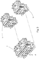
- FIG. 1 a plant for the production of granules is shown in side view.
- a creel 1 contains in a frame a larger number of unrollable fiber bundles, which are rolled up roughly in the form of a string on rollers of the creel 1 and can be unrolled therefrom in a controlled manner.
- the individual fiber bundles are then introduced into a tensioning unit 3, in which they are arranged parallel to one another and are each widened by tensioning.
- the fiber bundles are transferred from the tensioning unit to the impregnation unit 4, in which they are interspersed with polymer melt.
- the composite of fibers and polymer is cooled and at the end of the water bath section is brought into a cylindrical shape by means of forming rollers 6.
- a tape take-off 7 by means of which the longitudinal tension of the fiber-polymer composite can be maintained in the system.
- the fiber-polymer composite is then fed to a granulator 8 and divided into pellets / granules.
- FIG 2 shows a plan view of a plant Figure 1 .
- the spool gate is formed from two spool sub-gates 9 and 10 which are arranged side by side at an angle and each receive a number of spools.
- the fiber bundles drawn off therefrom run into the pre-tensioning unit 3, in which they are stretched and preheated and then fed to the impregnation unit 4, which is formed from two sub-units arranged in parallel.
- the impregnation unit is assigned an extruder 2 which makes the polymer melt available for the impregnation of the fiber bundles.
- the fiber bundle groups are processed in parallel in the further course of the process, but can also go through different further process steps if necessary.
- FIG 3 shows an impregnation unit 4, which is composed of two sub-units 11 and 12.
- the sub-units have the same structure and can each have one Treat group of fiber bundles.
- the impregnation unit 4 can also be formed from more than two sub-units. With a number of 20 fiber bundles to be processed in each case, 60 fiber bundles can thus be processed simultaneously with three sub-units.
- the sub-units are preferably flanged to one another via a screw connection 25. However, they can also be independent of one another.
- Figure 5 shows a disassembled sub-unit. This consists of a main part 19 which carries a lower guide plate 17 on the top. The main part is delimited by side parts 13 and 14 in the transverse direction. A front plate is located on the front side of the main part (seen against the direction of entry of the fibers) and an upper guide plate 16 is arranged on the top of the main part. A nozzle plate 18 is attached to the rear end.
- lower and upper guide plates 16 and 17 have a passage through which the fiber bundles are passed.
- the surfaces of the guide plates 16 and 17 are complementary to one another with an undulating surface 22 and 23, respectively.
- One half of the feed channel 21 can be seen on the front side of the main part 19, the other half of which (not shown) is formed on the rear side of the front part 15.
- the feed channel 21 opens at the top into a distributor area 20, in which the polymer melt fed in is distributed across the width and thus runs over the entire width of the front side of the main part.
- Figure 5 shows an end view of the front plate 15 with side parts 13 and 14. The figure shows in particular the inlet 27 into which the fiber bundles are introduced into the impregnation unit.
- Figure 6 shows a sectional view of a sub-unit with main part 19, front plate 15, upper guide plate 16, lower guide plate 17 and the passage 29 between the upper and lower guide plates 16 and 17.
- the fiber bundles are introduced into the impregnation unit via the inlet 27 and run through the under longitudinal tension Passage 29 until they emerge from the passage 29 via the outlet 28 and then emerge from the impregnation unit in a calibrated manner through the adjoining nozzle plate 18.
- the supply of the Polymer melt takes place from below via the feed channel 21, which is connected to an extruder.
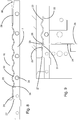
- Figure 8 shows an enlarged illustration of the arrangement of the guide plates 16 and 17 to one another.
- the arrangement of the plates defines a passage 29 of 0.5-8 mm, through which the fiber bundle 32 is drawn from the inlet 27 to the outlet 28. Due to the longitudinal tension applied to the fiber bundle, the fiber bundle contacts the respective mountain peaks of the wave-shaped guide plates at a number of points as it passes through the passage and is thereby better penetrated by polymer melt.
- a heating device 30 is used to maintain the required plasticity of the melt as the fiber bundle passes through.
- the polymer melt is fed to the passage via the melt channel 34, which extends over the entire width of the subunit, at the polymer outlet 33 and soaks the fiber bundle there.
- FIG. 8 shows a further enlarged view of the area in which the polymer melt enters the passage 29 at the inlet 26.
- the polymer outlet is located on a falling leg of the wave-shaped passage 29 between a valley and a mountain and is angled in the running direction of the fiber bundle so that the deflection angle of the melt when entering the passage 29 is minimized.
- the passage in this area is slightly enlarged in order to concentrate a larger amount of melt at this point.
- a tapering of the melt channel at the polymer inlet imposes a downstream direction on the melt, which serves to better fill the impregnation zone.
- the melt channel can be narrowed or widened via an adjustable, rail-like throttle point 36 in order to be able to vary the pressure of the polymer melt.
- the wave shape of the guide plates can also be designed to be vertically mirrored, so that the inlet 26 into the passage 29 is already on the first (rising) leg in the running direction of the fiber bundle between a valley and a mountain.
- the tension on the fiber bundles required in the impregnation device can be further increased by a tensioning area 35 with a reduced passage height following an inlet surface 24 and a subsequent arcuate shape 31 at the beginning of the undulating passage 29.
- the impregnation device can also contain a device for generating a slight oscillating movement of at least one of the guide plates.
Landscapes
- Engineering & Computer Science (AREA)
- Mechanical Engineering (AREA)
- Chemical & Material Sciences (AREA)
- Composite Materials (AREA)
- Reinforced Plastic Materials (AREA)
- Moulding By Coating Moulds (AREA)
Description
Die Erfindung bezieht sich auf eine Einrichtung zur Imprägnierung von Faserbündeln mit einer Polymerschmelze nach dem Oberbegriff des Anspruchs 1 sowie ein Verfahren nach dem Oberbegriff des Anspruchs 11.The invention relates to a device for impregnating fiber bundles with a polymer melt according to the preamble of
In vielen Industriebereichen werden Kunststoffmaterialen eingesetzt, die für Leichtbauelemente und andere Formteile verwendet werden, denen zur Gewichtseinsparung bei gleichzeitig hoher Festigkeit Fasermaterialen aus Glas- oder Kohlenstoff hinzugefügt sind. Solche Materialien werden u.a. vielfach in der Automobilindustrie und im Flugzeugbau eingesetzt.In many industrial sectors, plastic materials are used that are used for lightweight construction elements and other molded parts, to which fiber materials made of glass or carbon are added to save weight and at the same time provide high strength. Such materials are i.a. widely used in the automotive industry and in aircraft construction.
Zur Verstärkung von langgestreckten Baumaterialen, wie Rohren, Kabeln, Schläuchen etc. werden auch langgestreckte Fasermaterialien verwendet, die in Kunststoffe eingebettet sind und den Baumaterialen insbesondere eine Längsfestigkeit verleihen. Bereits ein geringer Faseranteil in den Kunststoffen führt zu beträchtlicher Festigkeitserhöhung.To reinforce elongated building materials such as pipes, cables, hoses, etc., elongated fiber materials are also used which are embedded in plastics and in particular give the building materials a longitudinal strength. Even a small proportion of fibers in the plastics leads to a considerable increase in strength.
Die Herstellung von faserverstärkten Kunststoffteilen erfolgt in der Regel über Spritzguss-, Fließpress-, Tiefzieh- oder Stranggussanlagen, denen die mit Fasern versetzten Kunststoffgranulate /-Pellets oder Kunststoffbändchen/ -Tapes zugeführt werden.Fiber-reinforced plastic parts are usually manufactured using injection molding, extrusion, deep-drawing or continuous casting systems, to which the plastic granules / pellets or plastic tapes / tapes are fed.
Für derartige Zwecke produzierte Granulate oder Bändchen werden üblicherweise dadurch hergestellt, dass von einem Vorrat abgezogene Endlosfasern in Form von sogenannten Rovings als Bündel feinster Fasern aus Glas, Kohlenstoff oder anderen Materialien, wie z. B. Aramid, zunächst über eine Spanneinrichtung ausgebreitet werden, dann mit einer Kunststoffschmelze durchtränkt, danach kalibriert und gekühlt werden und schließlich in Granulate von 3 - 50 mm Länge geteilt werden, oder als Endlosband aufgewickelt werden. Diese Granulate oder Bändchen werden dann an Kunststoff-Verarbeiter geliefert, die aus diesen Ausgangsstoffen Bauelemente unterschiedlicher Art herstellen.Granules or tapes produced for such purposes are usually produced by the fact that continuous fibers drawn from a supply in the form of so-called rovings as bundles of the finest fibers made of glass, carbon or other materials, such as. B. aramid, first spread over a tensioning device, then soaked with a plastic melt, then calibrated and cooled and finally divided into granules of 3 - 50 mm in length, or wound up as an endless belt. These granulates or tapes are then delivered to plastics processors who use these raw materials to manufacture various types of components.
Ein kritischer Schritt im Verfahrensablauf ist die Imprägnierung der Faserbündel mit Kunststoff. Es ist bekannt, die ausgebreiteten Faserbündel unter Spannung durch einen Durchlass zwischen zwei Führungsplatten hindurchzuführen, die korrespondierende wellenförmige Oberflächen enthalten, wobei die Faserbündel am Durchlasseingang von ober- oder unterseitig zugeführter Polymerschmelze durchdrungen werden. Im weiteren Durchlauf zwischen den Führungsplatten verbessert sich aufgrund eines mehrfachen Umlenkens und Kontaktierens der Faserbündel an Wellen [GD1] der Führungsplatten die Durchdringung mit der Polymerschmelze.A critical step in the process is the impregnation of the fiber bundles with plastic. It is known, the spread fiber bundle under tension by a Passing the passage between two guide plates which contain corresponding undulating surfaces, the fiber bundles at the passage entrance being penetrated by polymer melt fed in from above or below. In the further passage between the guide plates, the penetration of the polymer melt improves due to multiple deflections and contacting of the fiber bundles on shafts [GD1] of the guide plates.
Aus der
Die
In der
Dokument
Dokument
Die gleichmäßige Zufuhr von Kunststoffschmelze über die gesamte Breite der Imprägniereinheit ist kritisch. Insbesondere bei einer großen Zahl gleichzeitig zu bearbeitender Faserbündel ist es nur schwer möglich, die Druckverhältnisse, die Temperatur und die Fließgeschwindigkeit der Schmelze über die gesamte Breite des Durchlasses bzw. des Einlassbereichs für Schmelze in den Durchlass genügend genau einzustellen oder zu steuern.The uniform supply of plastic melt across the entire width of the impregnation unit is critical. Particularly with a large number of fiber bundles to be processed at the same time, it is difficult to adjust or control the pressure conditions, the temperature and the flow rate of the melt over the entire width of the passage or the inlet area for melt into the passage with sufficient accuracy.
Der Erfindung liegt daher die Aufgabe zugrunde, eine verbesserte Einrichtung zur Imprägnierung von Faserbündeln mit einer Polymerschmelze anzugeben, bei der die Homogenität der Durchdringung der Faserbündel verbessert ist, die Einrichtung einfach an unterschiedliche Bedarfe angepasst werden kann und auch in der Lage ist, mit einer Anlagengestaltung unterschiedliche Kunststoffmaterialen zu verarbeiten.The invention is therefore based on the object of specifying an improved device for the impregnation of fiber bundles with a polymer melt, in which the homogeneity of the penetration of the fiber bundles is improved, the device can be easily adapted to different needs and is also capable of having a system design to process different plastic materials.
Diese Aufgabe wird durch die in den Ansprüchen angegebene Erfindung gelöst. Vorteilhafte Weiterbildungen der Erfindung sind in Unteransprüchen angegeben.This object is achieved by the invention specified in the claims. Advantageous further developments of the invention are specified in the subclaims.
Die Erfindung geht aus von einer Einrichtung zur Imprägnierung von Faserbündeln mit einer Polymerschmelze, bei der die parallel zueinander in einen spaltförmigen Einlauf einer Imprägniereinheit eingeführten Faserbündel zwischen zwei mit definiertem Abstand komplementär zueinander angeordnete Führungsplatten mit wellenförmigen Oberflächen hindurchgeführt werden. Die Faserbündel werden während Ihres Durchlaufs durch die Imprägniereinheit mit der Polymerschmelze durchtränkt, welche im Anschluss an den spaltförmigen Einlauf in den Durchlass zwischen den Führungsplatten eingeführt wird.The invention is based on a device for impregnating fiber bundles with a polymer melt, in which the fiber bundles introduced parallel to one another into a slit-shaped inlet of an impregnation unit are passed between two guide plates with undulating surfaces arranged complementary to one another at a defined distance. As they pass through the impregnation unit, the fiber bundles are saturated with the polymer melt, which is introduced into the passage between the guide plates following the slit-shaped inlet.
Nach der Erfindung weist die Imprägniereinheit wenigstens zwei Durchlässe für jeweils eine definierte Anzahl von Faserbündeln auf, wobei die Durchlässe jeweils einen Einlass für Polymerschmelze aufweisen.According to the invention, the impregnation unit has at least two passages each for a defined number of fiber bundles, the passages each having an inlet for polymer melt.
Nach der Erfindung besteht die Imprägniereinheit daher aus wenigstens zwei parallel angeordneten Teileinheiten, die seitlich aneinander gekoppelt sind und jeweils einen Einlass für Polymerschmelze aufweisen, wobei die Teileinheiten jeweils einen spaltförmigen Einlauf und einen Auslauf für eine definierte Anzahl von Faserbündeln enthalten.According to the invention, the impregnation unit therefore consists of at least two parallel sub-units which are laterally coupled to one another and each have an inlet for polymer melt, the sub-units each containing a slit-shaped inlet and an outlet for a defined number of fiber bundles.
Anstelle einer möglichst großen Imprägniereinheit geht die Erfindung den umgekehrten Weg, indem sie die Imprägniereinheit in kleinere Einheiten unterteilt, denen die Polymerschmelze getrennt voneinander zugeführt wird. Daraus ergibt sich der Vorteil, dass die Einrichtung flexibel an unterschiedliche Bedarfe angepasst werden kann, wobei gleichzeitig eine vollständige Kontrolle der Parameter der Einrichtung gewährleistet bleibt. Diese Teilung ermöglicht es auch, an der Anlage in jeder Teileinheit unterschiedliche Parameter zu fahren, beispielsweise mit verschiedenen Kunststoffmaterialien oder Füllgraden.Instead of an impregnation unit that is as large as possible, the invention goes the opposite way, in that it divides the impregnation unit into smaller units to which the polymer melt is fed separately from one another. This results in the advantage that the device can be flexibly adapted to different requirements, while at the same time ensuring complete control of the device's parameters. This division also makes it possible to run different parameters on the system in each subunit, for example with different plastic materials or degrees of filling.
Bei geringer Auslastung der Anlage kann eine Teileinheit auch deaktiviert werden oder sogar problemlos abgeflanscht werden. Umgekehrt können bei größerem Bedarf zusätzliche Einheiten dazu geschaltet werden. Es ergibt sich damit eine hohe Flexibilität der Anlage und auch eine Einsparung an Energie und Kosten.If the system is not being used very well, a sub-unit can also be deactivated or even removed without any problems. Conversely, additional units can be added if the need arises. This results in a high degree of flexibility in the system and also a saving in energy and costs.
Zur weiteren Verbesserung der Imprägnierqualität sieht die Erfindung vorzugsweise vor, den Einlauf für die Faserbündel mit einem Bereich reduzierter Spalthöhe zu versehen, der die Faserbündel vor Eintritt in den Durchlass der Imprägniereinheit so umgelenkt, dass eine erhöhte Zugkraft auf die durch die Imprägniereinheit laufenden Faserbündel ausgeübt werden kann.To further improve the impregnation quality, the invention preferably provides for the inlet for the fiber bundles to be provided with an area of reduced gap height, which deflects the fiber bundles before entering the passage of the impregnation unit so that an increased tensile force is exerted on the fiber bundles running through the impregnation unit can.
Der Einlass der Polymerschmelze in den Durchlass zwischen den Führungsplatten befindet sich in bevorzugter Ausgestaltung der Erfindung zwischen einem Tal und einem Berg der Wellen der Führungsplatten, wobei die Durchlasshöhe zwischen den Führungsplatten im Einlassbereich der Polymerschmelze maximiert ist. Damit lässt sich eine verbesserte Temperatursteuerung der zugeführten Schmelze mit verbesserter definierter Durchdringung und Tränkung der Faserbündel herstellen. Zudem wird über eine Verjüngung am Polymereinlass der Schmelze eine Stromabwärtsrichtung auferlegt, die der besseren Füllung der Imprägnierzone dient.In a preferred embodiment of the invention, the inlet of the polymer melt into the passage between the guide plates is located between a valley and a mountain of the corrugations of the guide plates, the passage height between the guide plates being maximized in the inlet region of the polymer melt. In this way, an improved temperature control of the supplied melt with improved defined penetration and impregnation of the fiber bundles can be produced. In addition, a downward direction is imposed on the melt via a taper at the polymer inlet, which serves to better fill the impregnation zone.
Die Teileinheiten der Imprägniereinheit sind insbesondere aus einer Haupteinheit, die die Führungsplatten enthält, Seitenteilen, einer Frontplatte und einem stromabwärtigen Düsenplatte gebildet. Der Einlauf der Faserbündel befindet sich vorzugsweise zwischen der Oberseite der Frontplatte und einem vorderseitigen Ansatz der oberen Führungsplatte. Wenn mehrere Teileinheiten unmittelbar aneinander gekoppelt sind, ist zwischen zwei Teileinheiten jeweils nur ein gemeinsames Seitenteil erforderlich oder die Teileinheiten können in einer weiteren Ausgestaltung auch unmittelbar ohne gemeinsames Seitenteil gekoppelt werden.The sub-units of the impregnation unit are in particular formed from a main unit containing the guide plates, side parts, a front plate and a downstream nozzle plate. The inlet of the fiber bundle is preferably located between the top of the front plate and a front attachment of the upper guide plate. If several sub-units are directly coupled to one another, only one common side part is required between two sub-units or, in a further embodiment, the sub-units can also be coupled directly without a common side part.
Der jeweilige Zufuhrkanal zur Zuführung der Polymerschmelze befindet sich zwischen der Stirnseite des Hauptteils und der Frontplatte. Hier ist auch ein Verteilerbereich zur Verteilung der Polymerschmelze über die gesamte Breite einer Teileinheit ausgebildet. Die Ausbildung von Teileinheiten vereinfacht die Verteilung der Polymerschmelze daher in erheblichem Umfang.The respective supply channel for supplying the polymer melt is located between the front side of the main part and the front plate. A distribution area for distributing the polymer melt over the entire width of a subunit is also formed here. The formation of sub-units therefore simplifies the distribution of the polymer melt to a considerable extent.
Vorzugsweise kann jede Teileinheit eine Zahl von 3 - 70, vorzugsweise 10 - 30 Faserbündeln verarbeiten.Each sub-unit can preferably process a number of 3-70, preferably 10-30, fiber bundles.
Das erfindungsgemäße Verfahren sieht vorzugsweise vor, dass die Faserbündel vor ihrem Einlauf in die Imprägniereinheit in wenigstens zwei oder mehr Faserbündelgruppen aufgeteilt werden, die getrennt voneinander in jeweils eine Teileinheit eingeführt werden.The method according to the invention preferably provides that the fiber bundles are divided into at least two or more fiber bundle groups before they enter the impregnation unit, each of which is introduced into a subunit separately from one another.
In jeder Teileinheit können die Zugspannungen, Durchlaufgeschwindigkeiten Temperaturen und Drücke bei Bedarf variabel eingestellt oder geregelt werden.In each sub-unit, the tensile stresses, throughput speeds, temperatures and pressures can be variably set or regulated as required.
Den Teileinheiten können auch Polymerschmelzen unterschiedlichen Materials zugeführt werden.Polymer melts of different materials can also be fed to the subunits.
Schließlich können die Führungsplatten auch in eine schwingende, insbesondere niedrigfrequente sinusförmige Bewegung gebracht werden, um die Durchdringung der Fasern mit Polymerschmelze weiter zu verbessern.Finally, the guide plates can also be set in an oscillating, in particular low-frequency, sinusoidal movement in order to further improve the penetration of the fibers with polymer melt.
Die Erfindung wird nachstehend anhand eines Ausführungsbeispiels näher erläutert. Es zeigen:
- Fig. 1
- eine Übersichtsansicht einer Anlage zur Herstellung von mit Fasermaterial versetzten KunststoffGranulate in Seitenansicht,
- Fig. 2
- eine Anlage von
Fig. 1 in Aufsicht, - Fig. 3
- eine Imprägniereinheit, bestehend aus zwei Teileinheiten,
- Fig. 4
- eine Explosionsansicht der Einzelteile einer Teileinheit,
- Fig. 5
- eine Voransicht der Frontplatte einer Teileinheit,
- Fig. 6
- eine Schnittansicht durch eine Teileinheit,
- Fig. 7
- eine Vorderansicht des Hauptteils,
- Fig. 8
- eine Ansicht der Anordnung der Führungsplatten, und
- Fig. 9
- eine Detailansicht des Einlasses für Polymerschmelze in den Durchlass zwischen den Führungsplatten
- Fig. 1
- an overview view of a plant for the production of plastic granules mixed with fiber material in a side view,
- Fig. 2
- a plant of
Fig. 1 under supervision, - Fig. 3
- an impregnation unit, consisting of two sub-units,
- Fig. 4
- an exploded view of the individual parts of a sub-unit,
- Fig. 5
- a preview of the front panel of a sub-unit,
- Fig. 6
- a sectional view through a sub-unit,
- Fig. 7
- a front view of the main part,
- Fig. 8
- a view of the arrangement of the guide plates, and
- Fig. 9
- a detailed view of the inlet for polymer melt in the passage between the guide plates
Die erfindungsgemäße Einrichtung ist in der Lage, Faserbündel unterschiedlicher Art mit Polymermaterial zu imprägnieren. Unter Fasern ist jede Art von Fasern zu verstehen, die eine hohe Längsfestigkeit, wie Glasfasern, Carbonfasern, Feindrähte, Textilfäden, Aradmidfasern oder ähnliche Produkte aufweisen. Als zur Imprägnierung geeignetes Polymermaterial sind insbesondere PA, PP, PE und andere thermoplastische Kunststoffe zu nennen, die zur Ummantelung und Imprägnierung von Fasermaterialien geeignet sind. Thermoplastische Kunststoffe sind jedoch schwer mit Fasermaterialen zu verbinden, so dass eine intensive Durchdringung der Fasermaterialien in einer Imprägniereinheit erforderlich ist.The device according to the invention is able to impregnate fiber bundles of different types with polymer material. Fibers are to be understood as any type of fiber that has a high longitudinal strength, such as glass fibers, carbon fibers, fine wires, textile threads, aradmid fibers or similar products. Polymer materials suitable for impregnation include, in particular, PA, PP, PE and other thermoplastic plastics which are suitable for sheathing and impregnating fiber materials. However, thermoplastic plastics are difficult to combine with fiber materials, so that intensive penetration of the fiber materials in an impregnation unit is necessary.
Ein Roving ist eine Bündelung einer Vielzahl der vorgenannten Fasern zu einem Strang, der hier im Wesentlichen als Faserbündel bezeichnet wird. Die Zahl der Fasern in einem Strang kann bis zu mehrere Tausend betragen und ein Roving kann mehrere Kilometer lang sein. Er ist üblicherweise auf einer Rolle aufgerollt.A roving is a bundling of a large number of the aforementioned fibers to form a strand, which is here essentially referred to as a fiber bundle. The number of fibers in a strand can be up to several thousand and a roving can be several kilometers long. It is usually rolled up on a roll.
Nach der Imprägnierung und Umhüllung eines Rovings wird der erzeugte Strang in kurze Stücke zerteilt und als Granulat Kunststoff-Verarbeitern zur Weiterverarbeitung zur Verfügung gestellt. Diese können aus dem Granulat hochfeste und leichte Produkte herstellen, wie Rohre und andere Formteile. Im Falle der Bandherstellung werden die imprägnierten Rovings als Endlosband aufgewickelt.After a roving has been impregnated and wrapped, the strand produced is cut into short pieces and made available to plastics processors as granules for further processing. These can be made of high-strength, lightweight products from the granulate manufacture such as pipes and other fittings. In the case of tape production, the impregnated rovings are wound up as an endless tape.
In
Von der Spanneinheit werden die Faserbündel in die Imprägniereinheit 4 überführt, in der sie mit Polymerschmelze durchsetzt werden. In einer anschließenden Wasserbadstrecke 5 wird der Verbund aus Fasern und Polymer abgekühlt und am Ende der Wasserbadstrecke über Formrollen 6 in eine zylindrische Form gebracht. Es folgt ein Bandabzug 7, durch den die Längsspannung des Faser- Polymerverbunds in der Anlage aufrechterhalten werden kann. Der Faser- Polymerverbund wird dann einem Granulator 8 zugeführt und in Pellets / Granulat zerteilt.The fiber bundles are transferred from the tensioning unit to the
Der Imprägniereinheit ist ein Extruder 2 zugeordnet, der die Polymerschmelze zur Imprägnierung der Faserbündel zur Verfügung stellt. Die Faserbündelgruppen werden im weiteren Prozessablauf parallel verarbeitet, können aber auch bei Bedarf unterschiedliche weitere Prozessschritte durchlaufen.The impregnation unit is assigned an
Untere und obere Führungsplatten 16 und 17 weisen bei einem kleinen Abstand zueinander von 0,5 - 8 mm einen Durchlass auf, durch den die Faserbündel hindurchgeführt werden. Die Oberflächen der Führungsplatten 16 und 17 sind komplementär zueinander mit einer wellenförmigen Oberfläche 22 bzw. 23 versehen. An der Stirnseite des Hauptteils 19 ist eine Hälfte des Zufuhrkanals 21 zu sehen, dessen andere Hälfte (nicht dargestellt) an der Rückseite des Frontteils 15 ausgebildet ist. Der Zufuhrkanal 21 mündet nach oben hin in einen Verteilerbereich 20, in dem zugeführte Polymerschmelze in die Breite verteilt wird und somit über die gesamte Breite der Frontseite des Hauptteils verläuft.At a small distance from one another of 0.5-8 mm, lower and
In
Die Polymerschmelze wird dem Durchlass über den Schmelzekanal 34, der sich über die gesamte Breite der Teileinheit erstreckt, an dem Polymeraustritt 33 zugeführt und tränkt dort das Faserbündel.The polymer melt is fed to the passage via the
In weiterer Ausgestaltung kann der Schmelzekanal über eine einstellbare schienenartige Drosselstelle 36 verengt oder erweitert werden, um den Druck der Polymerschmelze variieren zu können.In a further embodiment, the melt channel can be narrowed or widened via an adjustable, rail-
Wenn der Einlass 26 in den Durchlass 29 weiter auf einen folgenden ansteigenden Schenkel zwischen einem Tal und einem Berg verschoben wird, kann noch ein flacherer Winkel des Eintritts der Schmelze in den Durchlass erreicht werden. Alternativ zur Darstellung in
Durch einen Spannbereich 35 mit verringerter Durchlasshöhe im Anschluss an eine Einlauffläche 24 und anschließender Bogenform 31 am Beginn des wellenförmigen Durchlasses 29 lässt sich die in der Imprägniereinrichtung erforderliche Spannung auf die Faserbündel weiter erhöhen.The tension on the fiber bundles required in the impregnation device can be further increased by a
Um eine noch weitere Verbesserung der Durchdringung der Polymerschmelze durch die Faserbündel zu erreichen kann die Imprägniereinrichtung auch eine Einrichtung zur Erzeugung einer geringen schwingenden Bewegung wenigstens einer der Führungsplatten enthalten.
Claims (15)
- Device for impregnating strand-like fiber bundles (32) with a polymer melt, in which device a plurality of fiber bundles (32), which are inserted in parallel with one another into a slot-like infeed (27) of an impregnation unit (4), are guided through between two guide plates (16, 17), which have undulating surfaces (22, 23), and are arranged so as to be complementary to one another at a defined spacing, and are discharged from the impregnation unit (4) via their outlet (28), the fiber bundles (32) being saturated with the polymer melt while passing through the impregnation unit (4), which polymer melt following the slot-like infeed (27) is introduced between the guide plates (16, 17) into the passage (29), characterized in that the impregnation unit (4) is formed from at least two sub-units (11, 12) arranged in parallel, which are coupled laterally to each other, and in each case contain a slot-like infeed (27) and an outlet (28) for a defined number of fiber bundles (32) in each case, the passages (29) each comprising an inlet (26) for polymer melt.
- Device according to claim 1, characterized in that the respective slot-like infeed (27) in the direction of travel of the fiber bundles has a region (35) of reduced slot height which makes a seamless transition into the respective passage between the guide plates (16, 17), and in that the passage height between the guide plates (16, 17) in the region of the inlet of the polymer melt is increased compared with the region of reduced slot height.
- Device according to claim 2, characterized in that the region of reduced slot height causes the fiber bundles to be deflected out of their direction of travel in the passage (29) by increasing the tensile force on the fiber bundles.
- Device according to claim 2, characterized in that the inlet (26) is located in the region of the first undulation peak or trough of the guide plates (16, 17) between a trough and a peak of the undulations of the guide plates (16, 17).
- Device according to claim 2, characterized in that the polymer outlet (33) has a channel constriction in front of the outlet (33), via which deflection of the polymer melt in the direction of travel of the fiber bundles takes place.
- Device according to claim 1, characterized in that the sub-units (11, 12) contain at their outlet (28) in each case a nozzle plate (18) by which the fiber bundles which are saturated with polymer melt are calibrated in diameter.
- Device according to claim 1, characterized in that the sub-units (11, 12) are formed in multiple parts with side parts (13, 14), a front plate (15) and a main part (19) comprising the guide plates (16, 17), the infeed (27) of the fiber bundles being formed between the upper side of the front plate (15) and a front region of the upper guide plate (16).
- Device according to claim 7, characterized in that the front plate (15) is flanged to the main part (19), and in that a feed channel (21) to the respective inlet (26) of polymer melt is formed between the end face of the main part (19) and the front plate (15).
- Device according to claim 8, characterized in that the feed channel (21) for supplying polymer melt comprises a distributor region (20) in which the polymer melt is widened to a melt ribbon running across the full width of the impregnation unit (4) or of the sub-units (11, 12), which melt ribbon is supplied to the inlet (26) between the guide plates (16, 17).
- Device according to claim 1, characterized in that the number of fiber bundles guided through each sub-unit (11, 12) is between 3 and 70, preferably 10 and 30.
- Method for impregnating fiber bundles with a polymer melt by using the device of claims 1 to 10, in which widely fanned-out fiber bundles (32) are guided through two guide plates (16, 17), arranged at a spacing from each other, which have undulating surfaces, to an impregnation unit (4), wherein the polymer melt is introduced into the infeed region of the guide plates (16, 17), and the fiber bundles while passing through the impregnation unit (4) are saturated by the polymer melt, wherein the fiber bundles prior to entering the impregnation unit (4) are divided into at least two fiber bundle groups which are introduced into sub-units (11, 12) of the impregnation unit (4) in each case and in each case are saturated by polymer melt supplied separately to the sub-units (11, 12).
- Method according to claim 11, characterized in that the tensile stresses and throughput rates of the fiber bundles of the individual fiber group bundles and/or the temperatures and pressures of the polymer melts can be controlled and regulated separately for each sub-unit (11, 12).
- Method according to claim 11, characterized in that polymer melts of different material are supplied to the sub-units (11, 12).
- Method according to claim 11, characterized in that the guide plates (16, 17) of the impregnation unit (4) are movable.
- Method according to claim 14, characterized in that at least one of the guide plates (16, 17) is subjected to an oscillating movement.
Priority Applications (14)
| Application Number | Priority Date | Filing Date | Title |
|---|---|---|---|
| DK17196681.5T DK3470196T3 (en) | 2017-10-16 | 2017-10-16 | Device and method for impregnating fiber bundles with a polymer melt |
| PL17196681T PL3470196T3 (en) | 2017-10-16 | 2017-10-16 | Device and method for the impregnation of fibre bundles with a polymer melt |
| ES17196681T ES2837148T3 (en) | 2017-10-16 | 2017-10-16 | Device and procedure for impregnating fiber bundles with a molten polymer |
| HUE17196681A HUE052818T2 (en) | 2017-10-16 | 2017-10-16 | Device and method for the impregnation of fibre bundles with a polymer melt |
| SI201730559T SI3470196T1 (en) | 2017-10-16 | 2017-10-16 | Device and method for the impregnation of fibre bundles with a polymer melt |
| EP17196681.5A EP3470196B1 (en) | 2017-10-16 | 2017-10-16 | Device and method for the impregnation of fibre bundles with a polymer melt |
| BR112020007530-2A BR112020007530B1 (en) | 2017-10-16 | 2018-10-05 | DEVICE AND METHOD FOR IMPREGNATING FIBERS BEAMS WITH A POLYMER MOLTEN |
| MX2020003866A MX2020003866A (en) | 2017-10-16 | 2018-10-05 | Device and method for impregnating fibre bundles with a polymer melt. |
| CN201880067155.3A CN111212714B (en) | 2017-10-16 | 2018-10-05 | Device and method for impregnating a fiber strand with a polymer melt |
| JP2020541855A JP7271560B2 (en) | 2017-10-16 | 2018-10-05 | Apparatus and method for impregnating fiber bundles with polymer melt |
| PCT/EP2018/077179 WO2019076653A1 (en) | 2017-10-16 | 2018-10-05 | Device and method for impregnating fibre bundles with a polymer melt |
| CA3078547A CA3078547A1 (en) | 2017-10-16 | 2018-10-05 | Device and method for impregnating fibre bundles with a polymer melt |
| KR1020207013439A KR102563337B1 (en) | 2017-10-16 | 2018-10-05 | Apparatus and method for impregnating fiber bundles with a polymer melt |
| US16/756,778 US11167449B2 (en) | 2017-10-16 | 2018-10-05 | Device and method for impregnating fiber bundles with a polymer melt |
Applications Claiming Priority (1)
| Application Number | Priority Date | Filing Date | Title |
|---|---|---|---|
| EP17196681.5A EP3470196B1 (en) | 2017-10-16 | 2017-10-16 | Device and method for the impregnation of fibre bundles with a polymer melt |
Publications (2)
| Publication Number | Publication Date |
|---|---|
| EP3470196A1 EP3470196A1 (en) | 2019-04-17 |
| EP3470196B1 true EP3470196B1 (en) | 2020-09-16 |
Family
ID=60119912
Family Applications (1)
| Application Number | Title | Priority Date | Filing Date |
|---|---|---|---|
| EP17196681.5A Active EP3470196B1 (en) | 2017-10-16 | 2017-10-16 | Device and method for the impregnation of fibre bundles with a polymer melt |
Country Status (14)
| Country | Link |
|---|---|
| US (1) | US11167449B2 (en) |
| EP (1) | EP3470196B1 (en) |
| JP (1) | JP7271560B2 (en) |
| KR (1) | KR102563337B1 (en) |
| CN (1) | CN111212714B (en) |
| BR (1) | BR112020007530B1 (en) |
| CA (1) | CA3078547A1 (en) |
| DK (1) | DK3470196T3 (en) |
| ES (1) | ES2837148T3 (en) |
| HU (1) | HUE052818T2 (en) |
| MX (1) | MX2020003866A (en) |
| PL (1) | PL3470196T3 (en) |
| SI (1) | SI3470196T1 (en) |
| WO (1) | WO2019076653A1 (en) |
Families Citing this family (4)
| Publication number | Priority date | Publication date | Assignee | Title |
|---|---|---|---|---|
| CN110065208A (en) * | 2019-04-26 | 2019-07-30 | 哈尔滨理工大学 | A kind of polyethylene insulation pellet mixing method |
| EP3974151A1 (en) | 2020-09-28 | 2022-03-30 | Feddem GmbH & Co. KG | Device and method for controlling the supply of polymer melt to a plastic processing machine |
| EP4294617A1 (en) * | 2021-02-17 | 2023-12-27 | Universidade do Minho | Impregnation device to produce continuous fibre reinforced thermoplastic filaments for 3d printing, and impregnation method thereof |
| CN116021804A (en) * | 2022-12-20 | 2023-04-28 | 青岛中集创赢复合材料科技有限公司 | Fiber impregnating device |
Family Cites Families (31)
| Publication number | Priority date | Publication date | Assignee | Title |
|---|---|---|---|---|
| US3874329A (en) * | 1973-05-29 | 1975-04-01 | Mcclean Anderson Inc | Device for coating a strand with a binding material |
| US4532169A (en) * | 1981-10-05 | 1985-07-30 | Ppg Industries, Inc. | High performance fiber ribbon product, high strength hybrid composites and methods of producing and using same |
| FR2613661B1 (en) * | 1987-04-09 | 1989-10-06 | Atochem | PROCESS FOR PRODUCING CONTINUOUS FIBER REINFORCED THERMOPLASTIC RESIN PROFILES, APPARATUS FOR OBTAINING SAME |
| FR2630967B1 (en) * | 1988-05-09 | 1993-12-10 | Atochem | PROCESS FOR THE MANUFACTURE OF LONG FIBER REINFORCED THERMOPLASTIC RESINS |
| US5277566A (en) | 1988-10-19 | 1994-01-11 | Hoechst Aktiengesellschaft | Extrusion impregnating device |
| US5447793A (en) * | 1989-10-20 | 1995-09-05 | Montsinger; Lawrence V. | Apparatus and method for forming fiber filled thermoplastic composite materials |
| US5116450A (en) * | 1990-07-23 | 1992-05-26 | Phillips Petroleum Company | Molding apparatus |
| US5198172A (en) * | 1990-07-23 | 1993-03-30 | Phillips Petroleum Company | Method of pultruding utilizing a die with changeable die insects |
| JPH0732495A (en) * | 1994-08-19 | 1995-02-03 | Polyplastics Co | Manufacture of long fiber-reinforced thermoplastic resin composition |
| JP3670321B2 (en) * | 1994-10-18 | 2005-07-13 | 住友化学株式会社 | Crosshead die and method for producing long fiber reinforced resin structure |
| KR100278254B1 (en) * | 1995-11-30 | 2001-01-15 | 고토 기치 | Method and apparatus for manufacturing long fiber reinforced resin structure |
| US6258453B1 (en) * | 1996-09-19 | 2001-07-10 | Lawrence V. Montsinger | Thermoplastic composite materials made by rotational shear |
| US6387179B1 (en) * | 1997-06-24 | 2002-05-14 | Hydril Company | Method and device for impregnating fiber bundles with resin |
| US20010001408A1 (en) * | 1997-11-03 | 2001-05-24 | Harry L. Belvin | Method and apparatus to febricate a fuly-consolidated fiber- reinforced tape from polymer powder preimpregnated fiber tow bundles for automated tow placement |
| WO1999024251A1 (en) * | 1997-11-07 | 1999-05-20 | Ube-Nitto Kasei Co., Ltd. | Fiber-reinforced composite hollow structure, method for production thereof, and appartus therefor |
| FR2807967B1 (en) * | 2000-04-25 | 2003-01-17 | Lapeyre | JOINING ELEMENT FORMED FROM EXTRUDABLE ORGANIC MATERIAL REINFORCED BY REINFORCING FIBERS, METHOD AND DEVICE FOR MANUFACTURING |
| DE10137924B4 (en) * | 2001-08-07 | 2005-12-01 | Ticona Gmbh | Long fiber-reinforced polyolefin-plastic structure, process for its preparation and moldings produced therefrom |
| JP2005305933A (en) | 2004-04-23 | 2005-11-04 | Daicel Chem Ind Ltd | Long fiber reinforced resin structure manufacturing apparatus, multi-stage crosshead die, and method for manufacturing the structure |
| KR20070029035A (en) * | 2004-07-08 | 2007-03-13 | 다이셀 가가꾸 고교 가부시끼가이샤 | Take-out device for long fiber reinforced resin structure and manufacturing method |
| JP4727960B2 (en) * | 2004-09-06 | 2011-07-20 | 株式会社プライムポリマー | Method for producing fiber reinforced resin composition |
| JP2006167982A (en) | 2004-12-13 | 2006-06-29 | Daicel Chem Ind Ltd | Method for producing long fiber reinforced thermoplastic resin structure |
| CN101868334A (en) * | 2007-10-02 | 2010-10-20 | 欧文斯-康宁玻璃纤维技术第二有限公司 | Impregnation die for manufacturing long fiber reinforced thermoplastic resin molding material |
| FR2967371B1 (en) * | 2010-11-17 | 2014-04-25 | Arkema France | METHOD FOR MANUFACTURING PRE-IMPREGNATED FIBROUS MATERIAL OF THERMOSETTING POLYMER |
| CA2775442C (en) | 2011-04-29 | 2019-01-08 | Ticona Llc | Impregnation section with upstream surface and method for impregnating fiber rovings |
| PL2701886T3 (en) * | 2011-04-29 | 2017-06-30 | Ticona Llc | Die with flow diffusing gate passage and method for impregnating fiber rovings |
| US9289936B2 (en) * | 2011-12-09 | 2016-03-22 | Ticona Llc | Impregnation section of die for impregnating fiber rovings |
| US9283708B2 (en) * | 2011-12-09 | 2016-03-15 | Ticona Llc | Impregnation section for impregnating fiber rovings |
| WO2013086259A1 (en) * | 2011-12-09 | 2013-06-13 | Ticona Llc | Die and method for impregnating fiber rovings |
| CN203752370U (en) * | 2014-01-25 | 2014-08-06 | 广州金发碳纤维新材料发展有限公司 | Double-sided-melted impregnation equipment of continuous long fiber reinforced thermoplastic resin |
| DE102014016289A1 (en) * | 2014-11-04 | 2016-05-04 | Protec Polymer Processing Gmbh | Method for producing unidirectionally fiber-reinforced plastic material and device for impregnating fiber material with extruded plastic |
| EP3842205B1 (en) | 2018-08-22 | 2023-08-16 | Toray Industries, Inc. | Method for producing thermoplastic resin-impregnated sheet-form reinforcing fiber bundle |
-
2017
- 2017-10-16 SI SI201730559T patent/SI3470196T1/en unknown
- 2017-10-16 EP EP17196681.5A patent/EP3470196B1/en active Active
- 2017-10-16 ES ES17196681T patent/ES2837148T3/en active Active
- 2017-10-16 DK DK17196681.5T patent/DK3470196T3/en active
- 2017-10-16 HU HUE17196681A patent/HUE052818T2/en unknown
- 2017-10-16 PL PL17196681T patent/PL3470196T3/en unknown
-
2018
- 2018-10-05 CA CA3078547A patent/CA3078547A1/en active Pending
- 2018-10-05 WO PCT/EP2018/077179 patent/WO2019076653A1/en active Application Filing
- 2018-10-05 US US16/756,778 patent/US11167449B2/en active Active
- 2018-10-05 KR KR1020207013439A patent/KR102563337B1/en active IP Right Grant
- 2018-10-05 JP JP2020541855A patent/JP7271560B2/en active Active
- 2018-10-05 BR BR112020007530-2A patent/BR112020007530B1/en active IP Right Grant
- 2018-10-05 MX MX2020003866A patent/MX2020003866A/en unknown
- 2018-10-05 CN CN201880067155.3A patent/CN111212714B/en active Active
Non-Patent Citations (1)
| Title |
|---|
| None * |
Also Published As
| Publication number | Publication date |
|---|---|
| MX2020003866A (en) | 2020-10-20 |
| CN111212714A (en) | 2020-05-29 |
| BR112020007530A2 (en) | 2020-10-06 |
| US11167449B2 (en) | 2021-11-09 |
| BR112020007530B1 (en) | 2022-07-05 |
| KR20200067872A (en) | 2020-06-12 |
| KR102563337B1 (en) | 2023-08-02 |
| HUE052818T2 (en) | 2021-05-28 |
| CA3078547A1 (en) | 2019-04-25 |
| DK3470196T3 (en) | 2020-12-21 |
| ES2837148T3 (en) | 2021-06-29 |
| WO2019076653A1 (en) | 2019-04-25 |
| EP3470196A1 (en) | 2019-04-17 |
| PL3470196T3 (en) | 2021-03-08 |
| JP7271560B2 (en) | 2023-05-11 |
| CN111212714B (en) | 2022-05-10 |
| US20200238573A1 (en) | 2020-07-30 |
| SI3470196T1 (en) | 2021-02-26 |
| JP2020536779A (en) | 2020-12-17 |
Similar Documents
| Publication | Publication Date | Title |
|---|---|---|
| EP0835175B1 (en) | Device and process for impregnating rovings with plastic material | |
| EP3470196B1 (en) | Device and method for the impregnation of fibre bundles with a polymer melt | |
| DE3888252T2 (en) | Process for the continuous production of fiber-reinforced thermoplastic prepregs and device for carrying out the same. | |
| DE69516795T2 (en) | Crosshead nozzle and method for producing a structural body made of plastic reinforced with long fibers | |
| DE102011010330B4 (en) | extrusion die | |
| DE69429736T2 (en) | METHOD FOR PRODUCING LONG-FIBER REINFORCED RESIN COMPOSITIONS | |
| DE69424444T2 (en) | HIGH-STRENGTH SOUL FOR WIRE ROPES | |
| EP3277473B1 (en) | Method for producing a fibre composite material | |
| EP3288739B1 (en) | Method and device for producing a fibrous composite component | |
| EP0691903B1 (en) | Process and device for producing glass fibre mat reinforced thermoplastic boards | |
| DE10059461A1 (en) | Process and plant for the production of fiber-reinforced plastic masses | |
| WO2011069910A1 (en) | Method and device for producing film strips | |
| DE2430576A1 (en) | MULTI-LAYER FIBER MAT | |
| EP1140459B1 (en) | Method for producing a compound from a flowable plastic material and a solid fiber core by means of extrusion and device for carrying out said method | |
| CH428185A (en) | Process for the production of workpieces made of plastics with at least longitudinal reinforcement inserts | |
| DE102010008529B4 (en) | Plant and method for manufacturing conveyor belts with steel cord core | |
| DE102011011790A1 (en) | Apparatus for extruding and cooling monofilament for e.g. artificial turf, has spinning nozzles which are arranged one behind other above cooling bath in extraction direction of monofilaments | |
| EP0035974A1 (en) | Device for producing a glass fibre reinforced plastics granulate | |
| DE102012112357A1 (en) | Method for manufacturing belt from plasticatable material for lift, involves placing endless forming tape into mold cavity and determining distance between deflection roller and forming wheel as thickness of belt | |
| DE2263324C3 (en) | Device for the continuous production of fiber-reinforced strip-shaped molding compounds | |
| EP2431152B1 (en) | Method and extrusion nozzle for producing reinforced hollow plastic profiles | |
| DE3717321A1 (en) | Production process for a sheet-like component and component | |
| DE3916407C2 (en) | ||
| DE2839381A1 (en) | METHOD AND DEVICE FOR MANUFACTURING GRANULES | |
| DE10039139A1 (en) | Feeding with reciprocation, directly from extruder into calender feed rollers, is achieved by extruding melt strands which are distributed into roller gap |
Legal Events
| Date | Code | Title | Description |
|---|---|---|---|
| PUAI | Public reference made under article 153(3) epc to a published international application that has entered the european phase |
Free format text: ORIGINAL CODE: 0009012 |
|
| STAA | Information on the status of an ep patent application or granted ep patent |
Free format text: STATUS: THE APPLICATION HAS BEEN PUBLISHED |
|
| AK | Designated contracting states |
Kind code of ref document: A1 Designated state(s): AL AT BE BG CH CY CZ DE DK EE ES FI FR GB GR HR HU IE IS IT LI LT LU LV MC MK MT NL NO PL PT RO RS SE SI SK SM TR |
|
| AX | Request for extension of the european patent |
Extension state: BA ME |
|
| STAA | Information on the status of an ep patent application or granted ep patent |
Free format text: STATUS: REQUEST FOR EXAMINATION WAS MADE |
|
| 17P | Request for examination filed |
Effective date: 20191015 |
|
| RBV | Designated contracting states (corrected) |
Designated state(s): AL AT BE BG CH CY CZ DE DK EE ES FI FR GB GR HR HU IE IS IT LI LT LU LV MC MK MT NL NO PL PT RO RS SE SI SK SM TR |
|
| GRAP | Despatch of communication of intention to grant a patent |
Free format text: ORIGINAL CODE: EPIDOSNIGR1 |
|
| STAA | Information on the status of an ep patent application or granted ep patent |
Free format text: STATUS: GRANT OF PATENT IS INTENDED |
|
| INTG | Intention to grant announced |
Effective date: 20200508 |
|
| RIN1 | Information on inventor provided before grant (corrected) |
Inventor name: GROSS, DIETER Inventor name: JOST, SEBASTIAN |
|
| GRAS | Grant fee paid |
Free format text: ORIGINAL CODE: EPIDOSNIGR3 |
|
| GRAA | (expected) grant |
Free format text: ORIGINAL CODE: 0009210 |
|
| STAA | Information on the status of an ep patent application or granted ep patent |
Free format text: STATUS: THE PATENT HAS BEEN GRANTED |
|
| AK | Designated contracting states |
Kind code of ref document: B1 Designated state(s): AL AT BE BG CH CY CZ DE DK EE ES FI FR GB GR HR HU IE IS IT LI LT LU LV MC MK MT NL NO PL PT RO RS SE SI SK SM TR |
|
| REG | Reference to a national code |
Ref country code: GB Ref legal event code: FG4D Free format text: NOT ENGLISH |
|
| REG | Reference to a national code |
Ref country code: CH Ref legal event code: EP |
|
| REG | Reference to a national code |
Ref country code: DE Ref legal event code: R096 Ref document number: 502017007273 Country of ref document: DE |
|
| REG | Reference to a national code |
Ref country code: IE Ref legal event code: FG4D Free format text: LANGUAGE OF EP DOCUMENT: GERMAN |
|
| REG | Reference to a national code |
Ref country code: AT Ref legal event code: REF Ref document number: 1313741 Country of ref document: AT Kind code of ref document: T Effective date: 20201015 |
|
| REG | Reference to a national code |
Ref country code: CH Ref legal event code: NV Representative=s name: DENNEMEYER AG, CH |
|
| REG | Reference to a national code |
Ref country code: FI Ref legal event code: FGE |
|
| REG | Reference to a national code |
Ref country code: RO Ref legal event code: EPE |
|
| REG | Reference to a national code |
Ref country code: NO Ref legal event code: T2 Effective date: 20200916 Ref country code: DK Ref legal event code: T3 Effective date: 20201216 |
|
| REG | Reference to a national code |
Ref country code: NL Ref legal event code: FP |
|
| REG | Reference to a national code |
Ref country code: SE Ref legal event code: TRGR |
|
| PG25 | Lapsed in a contracting state [announced via postgrant information from national office to epo] |
Ref country code: GR Free format text: LAPSE BECAUSE OF FAILURE TO SUBMIT A TRANSLATION OF THE DESCRIPTION OR TO PAY THE FEE WITHIN THE PRESCRIBED TIME-LIMIT Effective date: 20201217 Ref country code: HR Free format text: LAPSE BECAUSE OF FAILURE TO SUBMIT A TRANSLATION OF THE DESCRIPTION OR TO PAY THE FEE WITHIN THE PRESCRIBED TIME-LIMIT Effective date: 20200916 |
|
| REG | Reference to a national code |
Ref country code: SK Ref legal event code: T3 Ref document number: E 36036 Country of ref document: SK |
|
| PG25 | Lapsed in a contracting state [announced via postgrant information from national office to epo] |
Ref country code: LV Free format text: LAPSE BECAUSE OF FAILURE TO SUBMIT A TRANSLATION OF THE DESCRIPTION OR TO PAY THE FEE WITHIN THE PRESCRIBED TIME-LIMIT Effective date: 20200916 Ref country code: RS Free format text: LAPSE BECAUSE OF FAILURE TO SUBMIT A TRANSLATION OF THE DESCRIPTION OR TO PAY THE FEE WITHIN THE PRESCRIBED TIME-LIMIT Effective date: 20200916 |
|
| REG | Reference to a national code |
Ref country code: LT Ref legal event code: MG4D |
|
| PG25 | Lapsed in a contracting state [announced via postgrant information from national office to epo] |
Ref country code: PT Free format text: LAPSE BECAUSE OF FAILURE TO SUBMIT A TRANSLATION OF THE DESCRIPTION OR TO PAY THE FEE WITHIN THE PRESCRIBED TIME-LIMIT Effective date: 20210118 Ref country code: LT Free format text: LAPSE BECAUSE OF FAILURE TO SUBMIT A TRANSLATION OF THE DESCRIPTION OR TO PAY THE FEE WITHIN THE PRESCRIBED TIME-LIMIT Effective date: 20200916 Ref country code: EE Free format text: LAPSE BECAUSE OF FAILURE TO SUBMIT A TRANSLATION OF THE DESCRIPTION OR TO PAY THE FEE WITHIN THE PRESCRIBED TIME-LIMIT Effective date: 20200916 Ref country code: SM Free format text: LAPSE BECAUSE OF FAILURE TO SUBMIT A TRANSLATION OF THE DESCRIPTION OR TO PAY THE FEE WITHIN THE PRESCRIBED TIME-LIMIT Effective date: 20200916 |
|
| REG | Reference to a national code |
Ref country code: HU Ref legal event code: AG4A Ref document number: E052818 Country of ref document: HU |
|
| PG25 | Lapsed in a contracting state [announced via postgrant information from national office to epo] |
Ref country code: IS Free format text: LAPSE BECAUSE OF FAILURE TO SUBMIT A TRANSLATION OF THE DESCRIPTION OR TO PAY THE FEE WITHIN THE PRESCRIBED TIME-LIMIT Effective date: 20210116 Ref country code: PL Free format text: LAPSE BECAUSE OF FAILURE TO SUBMIT A TRANSLATION OF THE DESCRIPTION OR TO PAY THE FEE WITHIN THE PRESCRIBED TIME-LIMIT Effective date: 20200916 Ref country code: AL Free format text: LAPSE BECAUSE OF FAILURE TO SUBMIT A TRANSLATION OF THE DESCRIPTION OR TO PAY THE FEE WITHIN THE PRESCRIBED TIME-LIMIT Effective date: 20200916 |
|
| REG | Reference to a national code |
Ref country code: DE Ref legal event code: R097 Ref document number: 502017007273 Country of ref document: DE |
|
| PG25 | Lapsed in a contracting state [announced via postgrant information from national office to epo] |
Ref country code: LU Free format text: LAPSE BECAUSE OF NON-PAYMENT OF DUE FEES Effective date: 20201016 Ref country code: MC Free format text: LAPSE BECAUSE OF FAILURE TO SUBMIT A TRANSLATION OF THE DESCRIPTION OR TO PAY THE FEE WITHIN THE PRESCRIBED TIME-LIMIT Effective date: 20200916 |
|
| PLBE | No opposition filed within time limit |
Free format text: ORIGINAL CODE: 0009261 |
|
| STAA | Information on the status of an ep patent application or granted ep patent |
Free format text: STATUS: NO OPPOSITION FILED WITHIN TIME LIMIT |
|
| 26N | No opposition filed |
Effective date: 20210617 |
|
| PG25 | Lapsed in a contracting state [announced via postgrant information from national office to epo] |
Ref country code: IE Free format text: LAPSE BECAUSE OF NON-PAYMENT OF DUE FEES Effective date: 20201016 |
|
| PG25 | Lapsed in a contracting state [announced via postgrant information from national office to epo] |
Ref country code: MT Free format text: LAPSE BECAUSE OF FAILURE TO SUBMIT A TRANSLATION OF THE DESCRIPTION OR TO PAY THE FEE WITHIN THE PRESCRIBED TIME-LIMIT Effective date: 20200916 Ref country code: CY Free format text: LAPSE BECAUSE OF FAILURE TO SUBMIT A TRANSLATION OF THE DESCRIPTION OR TO PAY THE FEE WITHIN THE PRESCRIBED TIME-LIMIT Effective date: 20200916 |
|
| PG25 | Lapsed in a contracting state [announced via postgrant information from national office to epo] |
Ref country code: MK Free format text: LAPSE BECAUSE OF FAILURE TO SUBMIT A TRANSLATION OF THE DESCRIPTION OR TO PAY THE FEE WITHIN THE PRESCRIBED TIME-LIMIT Effective date: 20200916 |
|
| PGFP | Annual fee paid to national office [announced via postgrant information from national office to epo] |
Ref country code: SI Payment date: 20231005 Year of fee payment: 7 |
|
| P01 | Opt-out of the competence of the unified patent court (upc) registered |
Free format text: CASE NUMBER: APP_35779/2024 Effective date: 20240614 |
|
| PGFP | Annual fee paid to national office [announced via postgrant information from national office to epo] |
Ref country code: CZ Payment date: 20240927 Year of fee payment: 8 |
|
| PGFP | Annual fee paid to national office [announced via postgrant information from national office to epo] |
Ref country code: PL Payment date: 20240919 Year of fee payment: 8 |
|
| PGFP | Annual fee paid to national office [announced via postgrant information from national office to epo] |
Ref country code: SK Payment date: 20240930 Year of fee payment: 8 |
|
| PGFP | Annual fee paid to national office [announced via postgrant information from national office to epo] |
Ref country code: NL Payment date: 20241023 Year of fee payment: 8 |
|
| PGFP | Annual fee paid to national office [announced via postgrant information from national office to epo] |
Ref country code: HU Payment date: 20241010 Year of fee payment: 8 |
|
| PGFP | Annual fee paid to national office [announced via postgrant information from national office to epo] |
Ref country code: TR Payment date: 20240930 Year of fee payment: 8 |
|
| PGFP | Annual fee paid to national office [announced via postgrant information from national office to epo] |
Ref country code: DE Payment date: 20241030 Year of fee payment: 8 |
|
| PGFP | Annual fee paid to national office [announced via postgrant information from national office to epo] |
Ref country code: NO Payment date: 20241021 Year of fee payment: 8 |
|
| PGFP | Annual fee paid to national office [announced via postgrant information from national office to epo] |
Ref country code: DK Payment date: 20241025 Year of fee payment: 8 |
|
| PGFP | Annual fee paid to national office [announced via postgrant information from national office to epo] |
Ref country code: BE Payment date: 20241023 Year of fee payment: 8 Ref country code: FI Payment date: 20241024 Year of fee payment: 8 |
|
| PGFP | Annual fee paid to national office [announced via postgrant information from national office to epo] |
Ref country code: GB Payment date: 20241022 Year of fee payment: 8 |
|
| PGFP | Annual fee paid to national office [announced via postgrant information from national office to epo] |
Ref country code: BG Payment date: 20241029 Year of fee payment: 8 |
|
| PGFP | Annual fee paid to national office [announced via postgrant information from national office to epo] |
Ref country code: FR Payment date: 20241025 Year of fee payment: 8 Ref country code: AT Payment date: 20241018 Year of fee payment: 8 |
|
| PGFP | Annual fee paid to national office [announced via postgrant information from national office to epo] |
Ref country code: RO Payment date: 20241007 Year of fee payment: 8 |
|
| PGFP | Annual fee paid to national office [announced via postgrant information from national office to epo] |
Ref country code: ES Payment date: 20241118 Year of fee payment: 8 Ref country code: IT Payment date: 20241022 Year of fee payment: 8 |
|
| PGFP | Annual fee paid to national office [announced via postgrant information from national office to epo] |
Ref country code: SE Payment date: 20241025 Year of fee payment: 8 |
|
| PGFP | Annual fee paid to national office [announced via postgrant information from national office to epo] |
Ref country code: CH Payment date: 20241101 Year of fee payment: 8 |