EP3469608B1 - System zum positionieren einer medizinischen vorrichtung - Google Patents
System zum positionieren einer medizinischen vorrichtung Download PDFInfo
- Publication number
- EP3469608B1 EP3469608B1 EP17712698.4A EP17712698A EP3469608B1 EP 3469608 B1 EP3469608 B1 EP 3469608B1 EP 17712698 A EP17712698 A EP 17712698A EP 3469608 B1 EP3469608 B1 EP 3469608B1
- Authority
- EP
- European Patent Office
- Prior art keywords
- medical device
- controller
- button
- accelerometer
- electrical signal
- Prior art date
- Legal status (The legal status is an assumption and is not a legal conclusion. Google has not performed a legal analysis and makes no representation as to the accuracy of the status listed.)
- Active
Links
Images

Classifications
-
- H—ELECTRICITY
- H01—ELECTRIC ELEMENTS
- H01H—ELECTRIC SWITCHES; RELAYS; SELECTORS; EMERGENCY PROTECTIVE DEVICES
- H01H13/00—Switches having rectilinearly-movable operating part or parts adapted for pushing or pulling in one direction only, e.g. push-button switch
- H01H13/70—Switches having rectilinearly-movable operating part or parts adapted for pushing or pulling in one direction only, e.g. push-button switch having a plurality of operating members associated with different sets of contacts, e.g. keyboard
- H01H13/702—Switches having rectilinearly-movable operating part or parts adapted for pushing or pulling in one direction only, e.g. push-button switch having a plurality of operating members associated with different sets of contacts, e.g. keyboard with contacts carried by or formed from layers in a multilayer structure, e.g. membrane switches
-
- A—HUMAN NECESSITIES
- A61—MEDICAL OR VETERINARY SCIENCE; HYGIENE
- A61G—TRANSPORT, PERSONAL CONVEYANCES, OR ACCOMMODATION SPECIALLY ADAPTED FOR PATIENTS OR DISABLED PERSONS; OPERATING TABLES OR CHAIRS; CHAIRS FOR DENTISTRY; FUNERAL DEVICES
- A61G7/00—Beds specially adapted for nursing; Devices for lifting patients or disabled persons
- A61G7/002—Beds specially adapted for nursing; Devices for lifting patients or disabled persons having adjustable mattress frame
- A61G7/015—Beds specially adapted for nursing; Devices for lifting patients or disabled persons having adjustable mattress frame divided into different adjustable sections, e.g. for Gatch position
-
- A—HUMAN NECESSITIES
- A61—MEDICAL OR VETERINARY SCIENCE; HYGIENE
- A61G—TRANSPORT, PERSONAL CONVEYANCES, OR ACCOMMODATION SPECIALLY ADAPTED FOR PATIENTS OR DISABLED PERSONS; OPERATING TABLES OR CHAIRS; CHAIRS FOR DENTISTRY; FUNERAL DEVICES
- A61G7/00—Beds specially adapted for nursing; Devices for lifting patients or disabled persons
- A61G7/002—Beds specially adapted for nursing; Devices for lifting patients or disabled persons having adjustable mattress frame
- A61G7/018—Control or drive mechanisms
-
- G—PHYSICS
- G05—CONTROLLING; REGULATING
- G05B—CONTROL OR REGULATING SYSTEMS IN GENERAL; FUNCTIONAL ELEMENTS OF SUCH SYSTEMS; MONITORING OR TESTING ARRANGEMENTS FOR SUCH SYSTEMS OR ELEMENTS
- G05B15/00—Systems controlled by a computer
- G05B15/02—Systems controlled by a computer electric
-
- G—PHYSICS
- G05—CONTROLLING; REGULATING
- G05B—CONTROL OR REGULATING SYSTEMS IN GENERAL; FUNCTIONAL ELEMENTS OF SUCH SYSTEMS; MONITORING OR TESTING ARRANGEMENTS FOR SUCH SYSTEMS OR ELEMENTS
- G05B9/00—Safety arrangements
- G05B9/02—Safety arrangements electric
-
- H—ELECTRICITY
- H01—ELECTRIC ELEMENTS
- H01H—ELECTRIC SWITCHES; RELAYS; SELECTORS; EMERGENCY PROTECTIVE DEVICES
- H01H35/00—Switches operated by change of a physical condition
- H01H35/14—Switches operated by change of acceleration, e.g. by shock or vibration, inertia switch
-
- H—ELECTRICITY
- H01—ELECTRIC ELEMENTS
- H01H—ELECTRIC SWITCHES; RELAYS; SELECTORS; EMERGENCY PROTECTIVE DEVICES
- H01H9/00—Details of switching devices, not covered by groups H01H1/00 - H01H7/00
- H01H9/02—Bases, casings, or covers
- H01H9/0214—Hand-held casings
- H01H9/0235—Hand-held casings specially adapted for remote control, e.g. of audio or video apparatus
-
- A—HUMAN NECESSITIES
- A61—MEDICAL OR VETERINARY SCIENCE; HYGIENE
- A61G—TRANSPORT, PERSONAL CONVEYANCES, OR ACCOMMODATION SPECIALLY ADAPTED FOR PATIENTS OR DISABLED PERSONS; OPERATING TABLES OR CHAIRS; CHAIRS FOR DENTISTRY; FUNERAL DEVICES
- A61G2203/00—General characteristics of devices
- A61G2203/10—General characteristics of devices characterised by specific control means, e.g. for adjustment or steering
- A61G2203/12—Remote controls
-
- A—HUMAN NECESSITIES
- A61—MEDICAL OR VETERINARY SCIENCE; HYGIENE
- A61G—TRANSPORT, PERSONAL CONVEYANCES, OR ACCOMMODATION SPECIALLY ADAPTED FOR PATIENTS OR DISABLED PERSONS; OPERATING TABLES OR CHAIRS; CHAIRS FOR DENTISTRY; FUNERAL DEVICES
- A61G2203/00—General characteristics of devices
- A61G2203/30—General characteristics of devices characterised by sensor means
- A61G2203/36—General characteristics of devices characterised by sensor means for motion
-
- H—ELECTRICITY
- H01—ELECTRIC ELEMENTS
- H01H—ELECTRIC SWITCHES; RELAYS; SELECTORS; EMERGENCY PROTECTIVE DEVICES
- H01H2300/00—Orthogonal indexing scheme relating to electric switches, relays, selectors or emergency protective devices covered by H01H
- H01H2300/052—Controlling, signalling or testing correct functioning of a switch
Definitions
- the invention applies to a verification system used in the control of medical devices.
- patent number US7999797 A similar system as in patent application number US20100256947 is described in patent number US7999797 , where the device compares data measured by the accelerometer after tapping, for example, on the screen of a device, with the reference data, from which it then evaluates the place where there was a tap.
- the disadvantage of the aforementioned systems is the need to detect a wide range of forces applied to the control, the use of filtering tools being necessary to evaluate a tap.
- the complexity of configuring how data is filtered from the accelerometer for a wide range of forces applied to the control there may be incorrect evaluation of the relevance of the signal, for example a light tap or a very strong tap may be filtered out as an irrelevant signal or a random signal may be evaluated as relevant, both states being unacceptable, especially in a hospital environment.
- a medical device positioning system including a push-button controller, control system that is electrically connected to the button, an actuator electrically connected to the control system, and a verification system.
- the essence of the advantage consists of the fact that the verification system contains a calculation module and accelerometer mechanically connected to the controller.
- the controller is mechanically connected to at least one button with a switching element.
- the accelerometer is also electrically connected to the calculation module.
- the calculation module is also a part of the control system, which also contains at least one control unit.
- buttons consisting of a microswitch or membrane keypad.
- calculation module being an integral part of the controller.
- controller being a foot operated.
- a preferred method of using a medical device positioning system is that after activation of the button its switching element switches on and generates an electrical signal and a mechanical impact.
- the electrical signal generated by the switching element is transferred to the control system and the mechanical impact detected by an accelerometer, which then generates an electrical signal and sends it to the calculation module where it is then evaluated.
- the information is transferred to the control system, which, on the basis of this information and the electrical signal generated by the switching element, activates the actuator.
- a dangerous state may be, for example, the cracking or breaking of a flexible switching element due to material fatigue or mechanical damage, in which case an unintended electrical signal may be generated.
- a dangerous state may be, for example, the cracking or breaking of a flexible switching element due to material fatigue or mechanical damage, in which case an unintended electrical signal may be generated.
- a random mechanical impact may be generated, but there may not necessarily be an electrical signal generated by the switching element.
- One example of a version of the invention is a medical device positioning system according to claim 1.
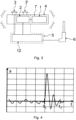
- the medical device positioning system consists of a medical device 8 , which may be a hospital bed, nursing bed, transport bed, transport chair, bedside cabinet, medical equipment holder, anti-decubitus mattress, or patient lifter. It also consists of an actuator 6 electrically connected to and controlled by a control system.
- the actuator 6 configures, for example, the backrest of the bed, the entire mattress platform of the bed, the patient lifter, or any other configurable part of the medical device 8 .
- the control system 5 is electrically connected to the controller 4 .
- the controller 4 may be hand operated, foot operated, or integrated into the medical device 8 . In hospital beds the controller 4 may be located, for example, in the side rail.
- the controller 4 contains one or more buttons 3 , 3' .
- the handset 4 is flexibly connected to the medical device 8 , and the flexible connection to the medical device 8 may, for example, be wired by cable, or wireless using radio, optical, or sonic communication.
- the controller 4 contains one or more buttons 3 ,
- the medical device positioning system consists of a controller 4 containing one or more buttons 3 , 3' .
- the button 3 may be for example, a micro switch on a printed circuit board, or a membrane keypad with flexible contact, or any other switch with a mechanical switching mechanism.
- the button 3 is electrically connected to the control system 5 .
- the controller 4 also contains an accelerometer 1 . mechanically linked to a printed circuit board or controller 4 on the medical device and is connected internally or externally and electrically to a calculation module 2 .
- the accelerometer 1 is also a part of the verification system 7 .
- One part of the verification system 7 is also a calculation module 2 .
- the calculation module 2 evaluates the output characteristics of the accelerometer - if a certain waveform of mechanical impact is detected in the output characteristics of the accelerometer, a signal is sent to the control system 5 , of which the calculation module is a 2 part.
- the control system 5 also consists of a control unit 12 .
- the control system 5 working according to the algorithm in picture 5 or picture 6 is connected electrically to the actuator 6 .
- the system consists of a controller 4 containing one or more buttons 3 , 3' .
- the button 3 may be for example, a micro switch on a printed circuit board, or a membrane keypad with flexible contact, or any other switch with a mechanical switching mechanism.
- the button 3 is electrically connected to the control system 5 .
- the controller 4 also contains an accelerometer 1 mechanically linked to a printed circuit board or controller 4 and is connected internally or externally and electrically to a calculation module 2 .
- the accelerometer 1 is also a part of the verification system 7 .
- the verification system 7 also contains a calculation module 2 located in the controller 4 .
- the calculation module 2 evaluates the output characteristics of the accelerometer - if a certain waveform of mechanical impact is detected in the output characteristics of the accelerometer, a signal is sent to the control system 5 of which the calculation module is a 2 part.
- the control system 5 also consists of a control unit 12 .
- the control system 5 working according to the algorithm in picture 5 or picture 6 is connected electrically with the actuator 6 .
- FIG 4 there is depiction of the output characteristics of the detected signal of the accelerometer 1 in a single axis.
- An accelerometer 1 detecting acceleration at least on one axis may be used. But it would be better to use a three-axis accelerometer 1 , to make it possible to significantly narrow the set of impacts that are identified as an intentional pressing of the button. In this way, not only is the waveform of the absolute value of the deviation caused by the impact measured, but also its direction in 3D space. Impacts in the wrong direction (for example, impact to the controller on the plane of the area on which the buttons are located) are not recognised as valid even if the waveform of the actual amplitude elements were themselves correct. This means that tapping the controller from the side does not cause confirmation of a valid press.
- the expected waveform of mechanical impact indicating a very rapid start with subsequent and gradual settling back to the original muffled signal is depicted.
- This waveform of the mechanical impact may be one element of the output characteristics from which it is filtered.
- the waveform of the mechanical impact results from closing the switching element of button 3 .
- the switching element of button 3 may be, for example, a flexible membrane capable of inducing a mechanical impact, which, after compressing the spring in button 3 switches to the on position, causing a mechanical impact and also closing the electrical contacts.
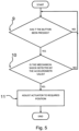
- buttons 3 and block 9 are used to evaluate whether button 3 was pressed. If it determines that button 3 has been pressed, it continues to block 10 detected mechanical impacts, otherwise the entire process returns to the state before block 9 press button 3 .
- the recorded mechanical impact block 10 data measured by the accelerometer 1 is evaluated when the switching element of the button is flipped, and the resultant mechanical impact corresponds to the waveform of the required mechanical impact.
- the waveform of the mechanical impact differs if, for example, button 3 is pressed by the patient lying on the controller 4 or if by impact of the controller 4 on the corner of a table button 3 is subsequently pressed, or if the operator moves the controller 4 and simultaneously presses button 3 . In such cases the waveform of the function is sought. If the values of the input characteristics of the accelerometer 1 correspond to the required mechanical impact waveform are identified, there is continuation to block 11 of actuator 6 configuration, otherwise the entire evaluation process returns to the state before block 9 of button 3 pressed. In the actuator 6 configuration block 11 , based on an evaluation of the button 3 press block 9 as well as a detected mechanical impact block, the actuator is configured in the required position depending on the relevant function of the pressed button 3 .
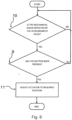
- the detected mechanical impact block 10 is used to evaluate whether the data measured by the accelerometer 1 depending on the acting forces corresponds to the required waveform of the mechanical impact.
- the waveform of the mechanical impact differs if, for example, button 3 is pressed by the patient lying on the controller 4 or by the impact of the controller 4 on the corner of a table and button 3 is subsequently pressed, or if the operator moves the controller 4 and at the same time presses button 3 . In such cases the desired waveform of a mechanical impact is sought. If the values of the input characteristics of the accelerometer 1 are evaluated corresponding to the waveform of the required mechanical impact, there is continuation to block 9 of button 3 pressed.
- the button 3 press block 9 is used to evaluate whether button 3 was pressed or whether there was just a random mechanical impact. If it is determined that button 3 was pressed, it continues to block 11 of actuator 6 configuration, otherwise the entire process returns to the state before block 10 of detected mechanical impact.
- the actuator 6 configuration block 11 based on evaluation of button 3 press block 9 and detected mechanical impact block 10 , the actuator is configured in the required position depending on the relevant function of the pressed button 3 .
- actuator 6 configuration block 11 If the values of the output characteristic of the accelerometer 1 correspond to the required mechanical impact waveform in the detected mechanical impact block 10 and also in button 3 press block 9, button 3 was pressed, it continues to actuator 6 configuration block 11 , otherwise the evaluation process is repeated.
- the actuator 6 configuration block 11 based on an evaluation of button 3 press block 9 and also a detected mechanical impact 10 block, the actuator is configured in the required position depending on the relevant function of the pressed button 3 .
Landscapes
- Health & Medical Sciences (AREA)
- Engineering & Computer Science (AREA)
- Nursing (AREA)
- Life Sciences & Earth Sciences (AREA)
- Animal Behavior & Ethology (AREA)
- General Health & Medical Sciences (AREA)
- Public Health (AREA)
- Veterinary Medicine (AREA)
- Automation & Control Theory (AREA)
- Physics & Mathematics (AREA)
- General Physics & Mathematics (AREA)
- Multimedia (AREA)
- General Engineering & Computer Science (AREA)
- Accommodation For Nursing Or Treatment Tables (AREA)
- Invalid Beds And Related Equipment (AREA)
- User Interface Of Digital Computer (AREA)
- Control Of Position Or Direction (AREA)
Claims (9)
- Ein Medizinprodukt (8), bestehend aus einem in seiner Lage verstellbaren Teil und einem System für die Positionierung des in seiner Lage verstellbaren Teils, System für die Positionierung, welches ferner einen Regler (4) mit einer Taste (3) umfasst, eines mit der Taste (3) elektrisch verbundenes Steuersystem (5), ein mit dem Steuersystem (5) elektrisch verbundener Aktuator (6), ein Testsystem (7) eines Computermoduls (2), welches dadurch gekennzeichnet ist, dass das System darüber hinaus einen Beschleunigungssensor (1) umfasst, wobei der Beschleunigungssensor mechanisch an einen Regler (4) zur Detektion mechanischer Erschütterungen und hiermit zur Generierung eines elektrischen Signals zum Zeitpunkt des Schaltens des Schaltelements der Taste (3) angeschlossen ist, indem der Regler (4) ferner mechanisch mit der Taste (3) mit dem Schaltelement verbunden ist, wobei der Beschleunigungssensor (1) zugleich elektrisch mit dem Computermodul (2) verbunden ist, welches Bestandteil des Steuersystem (5) ist, welches mindestens ein Steuergerät (12) enthält, wobei das Steuergerät (12) das beim Schalten des Schaltelements der Taste (3) generierte elektrische Signal auswertet und das durch den Beschleunigungssensor (1) generierte elektrische Signal in das Computermodul (2) gesendet und dort ausgewertet wird, wobei die verarbeitete Information in das Steuersystem (5) gesendet wird, welches auf der Grundlage dieser Information und des durch das Schaltelement generierten elektrisch Signals den Aktuator (6) aktiviert.
- Das Medizinprodukt (8) gemäß dem Patentanspruch 1, welches dadurch
gekennzeichnet ist, dass die Taste (3) aus einem Mikroschalter oder einer Folientastatur besteht. - Das Medizinprodukt (8) gemäß dem Patentanspruch 1, welches dadurch
gekennzeichnet ist, dass das Computermodul (2) integrierter Bestandteil des Reglers (4) ist. - Das Medizinprodukt (8) gemäß dem Patentanspruch 1, welches dadurch
gekennzeichnet ist, dass der Regler (4) die Form einer Fuß- oder Handbedienung bzw. einer in das Medizinprodukt (8) integrierten Bedienung hat. - Das Medizinprodukt (8) gemäß dem Patentanspruch 4, welches dadurch
gekennzeichnet ist, dass der Regler (4) mit das Medizinprodukt (8) drahtlos oder mittels eines Kabels verbunden ist. - Das Medizinprodukt (8) gemäß dem Patentanspruch 1, welches dadurch
gekennzeichnet ist, dass der Beschleunigungssensor (1) dreiachsig ausgeführt ist. - Das Medizinprodukt (8) gemäß dem Patentanspruch 1, welches dadurch gekennzeichnet ist, dass das elektrische Signal als Detektion einer bestimmten Form der Welle der mechanischen Erschütterung ausgewertet wird, indem die verarbeitete Information anschließend in das Steuersystem (5) gesendet wird, wo das Steuergerät (12) auf der Grundlage dieser Information und des elektrischen Signals den Aktuator (6) aktiviert.
- Das Medizinprodukt (8) gemäß dem Patentanspruch 1, welches dadurch gekennzeichnet ist, dass das Medizinprodukt aus der Gruppe jener Medizinprodukte (8) ausgewählt wird, welche ein Krankenhausbett, ein Pflegebett, ein Transportbett, einen Transportsessel, einen kleinen Betttisch, einen Halter medizinischen Zubehörs, eine Antidekubitusmatratze oder einen Patientenlifter umfasst.
- Das Medizinprodukt (8) gemäß dem Patentanspruch 1, welches dadurch gekennzeichnet ist, dass das in der Lage verstellbare Teil aus der Gruppe der in ihrer Lage verstellbaren Teile ausgewählt wird, die das Rückenteil, die Fläche für die Matratze oder den Patientenlifter umfassen.
Applications Claiming Priority (2)
| Application Number | Priority Date | Filing Date | Title |
|---|---|---|---|
| CZ2016162A CZ309269B6 (cs) | 2016-03-18 | 2016-03-18 | Systém pro polohování zdravotnického prostředku |
| PCT/CZ2017/000010 WO2017157353A1 (en) | 2016-03-18 | 2017-02-23 | System for positioning a medical device |
Publications (2)
| Publication Number | Publication Date |
|---|---|
| EP3469608A1 EP3469608A1 (de) | 2019-04-17 |
| EP3469608B1 true EP3469608B1 (de) | 2024-01-24 |
Family
ID=58397973
Family Applications (1)
| Application Number | Title | Priority Date | Filing Date |
|---|---|---|---|
| EP17712698.4A Active EP3469608B1 (de) | 2016-03-18 | 2017-02-23 | System zum positionieren einer medizinischen vorrichtung |
Country Status (7)
| Country | Link |
|---|---|
| US (1) | US10840036B2 (de) |
| EP (1) | EP3469608B1 (de) |
| CN (1) | CN108780711B (de) |
| CZ (1) | CZ309269B6 (de) |
| ES (1) | ES2970521T3 (de) |
| PL (1) | PL3469608T3 (de) |
| WO (1) | WO2017157353A1 (de) |
Families Citing this family (1)
| Publication number | Priority date | Publication date | Assignee | Title |
|---|---|---|---|---|
| US11096850B2 (en) | 2017-06-27 | 2021-08-24 | Stryker Corporation | Patient support apparatus control systems |
Family Cites Families (14)
| Publication number | Priority date | Publication date | Assignee | Title |
|---|---|---|---|---|
| DE19603318A1 (de) * | 1996-01-31 | 1997-08-14 | Dewert Antriebs Systemtech | Steuerungssystem für elektromotorisch betätigbare Verstelleinrichtungen für Krankenhausbetten |
| DE19647836A1 (de) | 1996-11-19 | 1998-05-20 | Roemheld A Gmbh & Co Kg | Ansteuerungssystem für elektromechanische Lineareinheiten zur Fehlersicherheit |
| US6369794B1 (en) * | 1998-09-09 | 2002-04-09 | Matsushita Electric Industrial Co., Ltd. | Operation indication outputting device for giving operation indication according to type of user's action |
| DE10238296B4 (de) * | 2002-08-21 | 2004-07-29 | Siemens Ag | Patiententrolley |
| US7618880B1 (en) | 2004-02-19 | 2009-11-17 | Quick Nathaniel R | Apparatus and method for transformation of substrate |
| DE102006051881A1 (de) | 2006-10-31 | 2008-05-08 | Siemens Ag | Patientenpositioniervorrichtung |
| US7999797B2 (en) * | 2006-12-26 | 2011-08-16 | Sony Ericsson Mobile Communications Ab | Detecting and locating a touch or a tap on an input surface |
| WO2010047932A1 (en) | 2008-10-21 | 2010-04-29 | Analog Devices, Inc. | Tap detection |
| WO2010114841A1 (en) | 2009-03-30 | 2010-10-07 | Kionix, Inc. | Directional tap detection algorithm using an accelerometer |
| US8537110B2 (en) | 2009-07-24 | 2013-09-17 | Empire Technology Development Llc | Virtual device buttons |
| JP2014515628A (ja) * | 2011-03-04 | 2014-07-03 | ストライカー コーポレイション | 患者支持装置のためのセンシングシステム |
| CN103366999B (zh) * | 2012-03-28 | 2015-12-02 | 比亚迪股份有限公司 | 一种汽车喇叭按压力控制装置、方法及汽车 |
| US9044361B2 (en) * | 2012-07-24 | 2015-06-02 | Hill-Rom Services, Inc. | Proxy caregiver interface |
| US9737355B2 (en) * | 2014-03-31 | 2017-08-22 | Ethicon Llc | Controlling impedance rise in electrosurgical medical devices |
-
2016
- 2016-03-18 CZ CZ2016162A patent/CZ309269B6/cs unknown
-
2017
- 2017-02-23 WO PCT/CZ2017/000010 patent/WO2017157353A1/en not_active Ceased
- 2017-02-23 CN CN201780018364.4A patent/CN108780711B/zh active Active
- 2017-02-23 PL PL17712698.4T patent/PL3469608T3/pl unknown
- 2017-02-23 US US16/130,369 patent/US10840036B2/en active Active
- 2017-02-23 EP EP17712698.4A patent/EP3469608B1/de active Active
- 2017-02-23 ES ES17712698T patent/ES2970521T3/es active Active
Also Published As
| Publication number | Publication date |
|---|---|
| PL3469608T3 (pl) | 2024-04-02 |
| WO2017157353A1 (en) | 2017-09-21 |
| US10840036B2 (en) | 2020-11-17 |
| CZ309269B6 (cs) | 2022-07-06 |
| CN108780711B (zh) | 2020-03-17 |
| CN108780711A (zh) | 2018-11-09 |
| ES2970521T3 (es) | 2024-05-29 |
| US20190122838A1 (en) | 2019-04-25 |
| CZ2016162A3 (cs) | 2017-12-13 |
| EP3469608A1 (de) | 2019-04-17 |
Similar Documents
| Publication | Publication Date | Title |
|---|---|---|
| US9436312B2 (en) | Input apparatus and control method for input apparatus | |
| EP3167946B1 (de) | Spielvorrichtung mit haptischer wirkung, die auf benutzereingangselemente begrenzt ist | |
| EP1965291A3 (de) | Verfahren und Vorrichtung für die haptische Rückkopplung mit Kippschalter | |
| KR101216489B1 (ko) | 입력장치 및 입력장치의 제어방법 | |
| EP2472369A1 (de) | Eingabevorrichtung und verfahren zur steuerung der eingabevorrichtung | |
| KR20120040233A (ko) | 입력장치 및 입력장치의 제어방법 | |
| KR20120042879A (ko) | 입력장치, 입력장치의 제어방법, 촉감제공장치 및 촉감제공장치의 제어방법 | |
| KR20120025002A (ko) | 입력장치 및 입력장치의 제어방법 | |
| US10123631B2 (en) | Operating system for, and a method of, operating an article of furniture | |
| JP6069812B2 (ja) | 速度制御を備えた台所用機器 | |
| CN110712576A (zh) | 具有座椅操作装置的车辆座椅 | |
| EP3469608B1 (de) | System zum positionieren einer medizinischen vorrichtung | |
| WO2000025636A1 (en) | Control of powered furniture | |
| WO2012143053A1 (en) | A hand-held terminal unit, an industrial robot system and a method for controlling an industrial robot | |
| US6973368B2 (en) | Method and device for reliably switching an operating mode of an industrial controller for machine tools or production machines | |
| CN103313688A (zh) | 电动的家具驱动装置 | |
| US20110051967A1 (en) | Hearing aid with protection against unintentional operation | |
| EP1891617B1 (de) | Ausfallsichere fernsteuerung | |
| CN109690712A (zh) | 转换操作元件 | |
| KR101529303B1 (ko) | 비데 장치 | |
| EP3742462B1 (de) | Schaltvorrichtung und medizinische vorrichtung mit der schaltvorrichtung | |
| KR101299625B1 (ko) | 터치 입력 장치, 이를 구비하는 디지털 기기 및 제어 방법 | |
| JP2003084803A (ja) | 携帯型操作装置 | |
| JP2018129208A (ja) | キースイッチ及びキーボード | |
| NZ730257B2 (en) | An operating system for, and a method of, operating an article of furniture |
Legal Events
| Date | Code | Title | Description |
|---|---|---|---|
| STAA | Information on the status of an ep patent application or granted ep patent |
Free format text: STATUS: UNKNOWN |
|
| STAA | Information on the status of an ep patent application or granted ep patent |
Free format text: STATUS: THE INTERNATIONAL PUBLICATION HAS BEEN MADE |
|
| PUAI | Public reference made under article 153(3) epc to a published international application that has entered the european phase |
Free format text: ORIGINAL CODE: 0009012 |
|
| STAA | Information on the status of an ep patent application or granted ep patent |
Free format text: STATUS: REQUEST FOR EXAMINATION WAS MADE |
|
| 17P | Request for examination filed |
Effective date: 20190228 |
|
| AK | Designated contracting states |
Kind code of ref document: A1 Designated state(s): AL AT BE BG CH CY CZ DE DK EE ES FI FR GB GR HR HU IE IS IT LI LT LU LV MC MK MT NL NO PL PT RO RS SE SI SK SM TR |
|
| AX | Request for extension of the european patent |
Extension state: BA ME |
|
| DAV | Request for validation of the european patent (deleted) | ||
| DAX | Request for extension of the european patent (deleted) | ||
| STAA | Information on the status of an ep patent application or granted ep patent |
Free format text: STATUS: EXAMINATION IS IN PROGRESS |
|
| 17Q | First examination report despatched |
Effective date: 20200811 |
|
| GRAP | Despatch of communication of intention to grant a patent |
Free format text: ORIGINAL CODE: EPIDOSNIGR1 |
|
| STAA | Information on the status of an ep patent application or granted ep patent |
Free format text: STATUS: GRANT OF PATENT IS INTENDED |
|
| INTG | Intention to grant announced |
Effective date: 20231102 |
|
| GRAS | Grant fee paid |
Free format text: ORIGINAL CODE: EPIDOSNIGR3 |
|
| GRAA | (expected) grant |
Free format text: ORIGINAL CODE: 0009210 |
|
| STAA | Information on the status of an ep patent application or granted ep patent |
Free format text: STATUS: THE PATENT HAS BEEN GRANTED |
|
| AK | Designated contracting states |
Kind code of ref document: B1 Designated state(s): AL AT BE BG CH CY CZ DE DK EE ES FI FR GB GR HR HU IE IS IT LI LT LU LV MC MK MT NL NO PL PT RO RS SE SI SK SM TR |
|
| REG | Reference to a national code |
Ref country code: GB Ref legal event code: FG4D |
|
| REG | Reference to a national code |
Ref country code: CH Ref legal event code: EP |
|
| REG | Reference to a national code |
Ref country code: DE Ref legal event code: R096 Ref document number: 602017078667 Country of ref document: DE |
|
| REG | Reference to a national code |
Ref country code: IE Ref legal event code: FG4D |
|
| REG | Reference to a national code |
Ref country code: NL Ref legal event code: FP |
|
| REG | Reference to a national code |
Ref country code: SE Ref legal event code: TRGR |
|
| REG | Reference to a national code |
Ref country code: SK Ref legal event code: T3 Ref document number: E 43500 Country of ref document: SK |
|
| REG | Reference to a national code |
Ref country code: LT Ref legal event code: MG9D |
|
| REG | Reference to a national code |
Ref country code: ES Ref legal event code: FG2A Ref document number: 2970521 Country of ref document: ES Kind code of ref document: T3 Effective date: 20240529 |
|
| PG25 | Lapsed in a contracting state [announced via postgrant information from national office to epo] |
Ref country code: IS Free format text: LAPSE BECAUSE OF FAILURE TO SUBMIT A TRANSLATION OF THE DESCRIPTION OR TO PAY THE FEE WITHIN THE PRESCRIBED TIME-LIMIT Effective date: 20240524 |
|
| PG25 | Lapsed in a contracting state [announced via postgrant information from national office to epo] |
Ref country code: LT Free format text: LAPSE BECAUSE OF FAILURE TO SUBMIT A TRANSLATION OF THE DESCRIPTION OR TO PAY THE FEE WITHIN THE PRESCRIBED TIME-LIMIT Effective date: 20240124 |
|
| PG25 | Lapsed in a contracting state [announced via postgrant information from national office to epo] |
Ref country code: GR Free format text: LAPSE BECAUSE OF FAILURE TO SUBMIT A TRANSLATION OF THE DESCRIPTION OR TO PAY THE FEE WITHIN THE PRESCRIBED TIME-LIMIT Effective date: 20240425 |
|
| REG | Reference to a national code |
Ref country code: AT Ref legal event code: MK05 Ref document number: 1652853 Country of ref document: AT Kind code of ref document: T Effective date: 20240124 |
|
| PG25 | Lapsed in a contracting state [announced via postgrant information from national office to epo] |
Ref country code: RS Free format text: LAPSE BECAUSE OF FAILURE TO SUBMIT A TRANSLATION OF THE DESCRIPTION OR TO PAY THE FEE WITHIN THE PRESCRIBED TIME-LIMIT Effective date: 20240424 Ref country code: HR Free format text: LAPSE BECAUSE OF FAILURE TO SUBMIT A TRANSLATION OF THE DESCRIPTION OR TO PAY THE FEE WITHIN THE PRESCRIBED TIME-LIMIT Effective date: 20240124 |
|
| PG25 | Lapsed in a contracting state [announced via postgrant information from national office to epo] |
Ref country code: AT Free format text: LAPSE BECAUSE OF FAILURE TO SUBMIT A TRANSLATION OF THE DESCRIPTION OR TO PAY THE FEE WITHIN THE PRESCRIBED TIME-LIMIT Effective date: 20240124 |
|
| PG25 | Lapsed in a contracting state [announced via postgrant information from national office to epo] |
Ref country code: RS Free format text: LAPSE BECAUSE OF FAILURE TO SUBMIT A TRANSLATION OF THE DESCRIPTION OR TO PAY THE FEE WITHIN THE PRESCRIBED TIME-LIMIT Effective date: 20240424 Ref country code: NO Free format text: LAPSE BECAUSE OF FAILURE TO SUBMIT A TRANSLATION OF THE DESCRIPTION OR TO PAY THE FEE WITHIN THE PRESCRIBED TIME-LIMIT Effective date: 20240424 Ref country code: LT Free format text: LAPSE BECAUSE OF FAILURE TO SUBMIT A TRANSLATION OF THE DESCRIPTION OR TO PAY THE FEE WITHIN THE PRESCRIBED TIME-LIMIT Effective date: 20240124 Ref country code: IS Free format text: LAPSE BECAUSE OF FAILURE TO SUBMIT A TRANSLATION OF THE DESCRIPTION OR TO PAY THE FEE WITHIN THE PRESCRIBED TIME-LIMIT Effective date: 20240524 Ref country code: HR Free format text: LAPSE BECAUSE OF FAILURE TO SUBMIT A TRANSLATION OF THE DESCRIPTION OR TO PAY THE FEE WITHIN THE PRESCRIBED TIME-LIMIT Effective date: 20240124 Ref country code: GR Free format text: LAPSE BECAUSE OF FAILURE TO SUBMIT A TRANSLATION OF THE DESCRIPTION OR TO PAY THE FEE WITHIN THE PRESCRIBED TIME-LIMIT Effective date: 20240425 Ref country code: FI Free format text: LAPSE BECAUSE OF FAILURE TO SUBMIT A TRANSLATION OF THE DESCRIPTION OR TO PAY THE FEE WITHIN THE PRESCRIBED TIME-LIMIT Effective date: 20240124 Ref country code: BG Free format text: LAPSE BECAUSE OF FAILURE TO SUBMIT A TRANSLATION OF THE DESCRIPTION OR TO PAY THE FEE WITHIN THE PRESCRIBED TIME-LIMIT Effective date: 20240124 Ref country code: AT Free format text: LAPSE BECAUSE OF FAILURE TO SUBMIT A TRANSLATION OF THE DESCRIPTION OR TO PAY THE FEE WITHIN THE PRESCRIBED TIME-LIMIT Effective date: 20240124 |
|
| PG25 | Lapsed in a contracting state [announced via postgrant information from national office to epo] |
Ref country code: PT Free format text: LAPSE BECAUSE OF FAILURE TO SUBMIT A TRANSLATION OF THE DESCRIPTION OR TO PAY THE FEE WITHIN THE PRESCRIBED TIME-LIMIT Effective date: 20240524 |
|
| PG25 | Lapsed in a contracting state [announced via postgrant information from national office to epo] |
Ref country code: PT Free format text: LAPSE BECAUSE OF FAILURE TO SUBMIT A TRANSLATION OF THE DESCRIPTION OR TO PAY THE FEE WITHIN THE PRESCRIBED TIME-LIMIT Effective date: 20240524 Ref country code: LV Free format text: LAPSE BECAUSE OF FAILURE TO SUBMIT A TRANSLATION OF THE DESCRIPTION OR TO PAY THE FEE WITHIN THE PRESCRIBED TIME-LIMIT Effective date: 20240124 |
|
| PG25 | Lapsed in a contracting state [announced via postgrant information from national office to epo] |
Ref country code: DK Free format text: LAPSE BECAUSE OF FAILURE TO SUBMIT A TRANSLATION OF THE DESCRIPTION OR TO PAY THE FEE WITHIN THE PRESCRIBED TIME-LIMIT Effective date: 20240124 |
|
| PG25 | Lapsed in a contracting state [announced via postgrant information from national office to epo] |
Ref country code: SM Free format text: LAPSE BECAUSE OF FAILURE TO SUBMIT A TRANSLATION OF THE DESCRIPTION OR TO PAY THE FEE WITHIN THE PRESCRIBED TIME-LIMIT Effective date: 20240124 |
|
| PG25 | Lapsed in a contracting state [announced via postgrant information from national office to epo] |
Ref country code: LU Free format text: LAPSE BECAUSE OF NON-PAYMENT OF DUE FEES Effective date: 20240223 |
|
| PG25 | Lapsed in a contracting state [announced via postgrant information from national office to epo] |
Ref country code: EE Free format text: LAPSE BECAUSE OF FAILURE TO SUBMIT A TRANSLATION OF THE DESCRIPTION OR TO PAY THE FEE WITHIN THE PRESCRIBED TIME-LIMIT Effective date: 20240124 Ref country code: CZ Free format text: LAPSE BECAUSE OF FAILURE TO SUBMIT A TRANSLATION OF THE DESCRIPTION OR TO PAY THE FEE WITHIN THE PRESCRIBED TIME-LIMIT Effective date: 20240124 |
|
| REG | Reference to a national code |
Ref country code: DE Ref legal event code: R097 Ref document number: 602017078667 Country of ref document: DE |
|
| PG25 | Lapsed in a contracting state [announced via postgrant information from national office to epo] |
Ref country code: SM Free format text: LAPSE BECAUSE OF FAILURE TO SUBMIT A TRANSLATION OF THE DESCRIPTION OR TO PAY THE FEE WITHIN THE PRESCRIBED TIME-LIMIT Effective date: 20240124 Ref country code: RO Free format text: LAPSE BECAUSE OF FAILURE TO SUBMIT A TRANSLATION OF THE DESCRIPTION OR TO PAY THE FEE WITHIN THE PRESCRIBED TIME-LIMIT Effective date: 20240124 Ref country code: LU Free format text: LAPSE BECAUSE OF NON-PAYMENT OF DUE FEES Effective date: 20240223 Ref country code: EE Free format text: LAPSE BECAUSE OF FAILURE TO SUBMIT A TRANSLATION OF THE DESCRIPTION OR TO PAY THE FEE WITHIN THE PRESCRIBED TIME-LIMIT Effective date: 20240124 Ref country code: DK Free format text: LAPSE BECAUSE OF FAILURE TO SUBMIT A TRANSLATION OF THE DESCRIPTION OR TO PAY THE FEE WITHIN THE PRESCRIBED TIME-LIMIT Effective date: 20240124 Ref country code: CZ Free format text: LAPSE BECAUSE OF FAILURE TO SUBMIT A TRANSLATION OF THE DESCRIPTION OR TO PAY THE FEE WITHIN THE PRESCRIBED TIME-LIMIT Effective date: 20240124 |
|
| PG25 | Lapsed in a contracting state [announced via postgrant information from national office to epo] |
Ref country code: MC Free format text: LAPSE BECAUSE OF FAILURE TO SUBMIT A TRANSLATION OF THE DESCRIPTION OR TO PAY THE FEE WITHIN THE PRESCRIBED TIME-LIMIT Effective date: 20240124 |
|
| PG25 | Lapsed in a contracting state [announced via postgrant information from national office to epo] |
Ref country code: MC Free format text: LAPSE BECAUSE OF FAILURE TO SUBMIT A TRANSLATION OF THE DESCRIPTION OR TO PAY THE FEE WITHIN THE PRESCRIBED TIME-LIMIT Effective date: 20240124 |
|
| PLBE | No opposition filed within time limit |
Free format text: ORIGINAL CODE: 0009261 |
|
| STAA | Information on the status of an ep patent application or granted ep patent |
Free format text: STATUS: NO OPPOSITION FILED WITHIN TIME LIMIT |
|
| REG | Reference to a national code |
Ref country code: BE Ref legal event code: MM Effective date: 20240229 |
|
| 26N | No opposition filed |
Effective date: 20241025 |
|
| PG25 | Lapsed in a contracting state [announced via postgrant information from national office to epo] |
Ref country code: BE Free format text: LAPSE BECAUSE OF NON-PAYMENT OF DUE FEES Effective date: 20240229 |
|
| PG25 | Lapsed in a contracting state [announced via postgrant information from national office to epo] |
Ref country code: IE Free format text: LAPSE BECAUSE OF NON-PAYMENT OF DUE FEES Effective date: 20240223 |
|
| PG25 | Lapsed in a contracting state [announced via postgrant information from national office to epo] |
Ref country code: IE Free format text: LAPSE BECAUSE OF NON-PAYMENT OF DUE FEES Effective date: 20240223 Ref country code: BE Free format text: LAPSE BECAUSE OF NON-PAYMENT OF DUE FEES Effective date: 20240229 |
|
| PGFP | Annual fee paid to national office [announced via postgrant information from national office to epo] |
Ref country code: DE Payment date: 20250108 Year of fee payment: 9 |
|
| PGFP | Annual fee paid to national office [announced via postgrant information from national office to epo] |
Ref country code: ES Payment date: 20250301 Year of fee payment: 9 |
|
| PGFP | Annual fee paid to national office [announced via postgrant information from national office to epo] |
Ref country code: SE Payment date: 20250109 Year of fee payment: 9 |
|
| PG25 | Lapsed in a contracting state [announced via postgrant information from national office to epo] |
Ref country code: SI Free format text: LAPSE BECAUSE OF FAILURE TO SUBMIT A TRANSLATION OF THE DESCRIPTION OR TO PAY THE FEE WITHIN THE PRESCRIBED TIME-LIMIT Effective date: 20240124 |
|
| PGFP | Annual fee paid to national office [announced via postgrant information from national office to epo] |
Ref country code: CH Payment date: 20250301 Year of fee payment: 9 |
|
| PGFP | Annual fee paid to national office [announced via postgrant information from national office to epo] |
Ref country code: FR Payment date: 20250227 Year of fee payment: 9 Ref country code: PL Payment date: 20250109 Year of fee payment: 9 |
|
| PGFP | Annual fee paid to national office [announced via postgrant information from national office to epo] |
Ref country code: GB Payment date: 20250109 Year of fee payment: 9 Ref country code: SK Payment date: 20250108 Year of fee payment: 9 Ref country code: IT Payment date: 20250108 Year of fee payment: 9 |
|
| PGFP | Annual fee paid to national office [announced via postgrant information from national office to epo] |
Ref country code: TR Payment date: 20250221 Year of fee payment: 9 |
|
| PG25 | Lapsed in a contracting state [announced via postgrant information from national office to epo] |
Ref country code: CY Free format text: LAPSE BECAUSE OF FAILURE TO SUBMIT A TRANSLATION OF THE DESCRIPTION OR TO PAY THE FEE WITHIN THE PRESCRIBED TIME-LIMIT; INVALID AB INITIO Effective date: 20170223 |
|
| PG25 | Lapsed in a contracting state [announced via postgrant information from national office to epo] |
Ref country code: HU Free format text: LAPSE BECAUSE OF FAILURE TO SUBMIT A TRANSLATION OF THE DESCRIPTION OR TO PAY THE FEE WITHIN THE PRESCRIBED TIME-LIMIT; INVALID AB INITIO Effective date: 20170223 |
|
| PGFP | Annual fee paid to national office [announced via postgrant information from national office to epo] |
Ref country code: NL Payment date: 20260123 Year of fee payment: 10 |
|
| REG | Reference to a national code |
Ref country code: CH Ref legal event code: U11 Free format text: ST27 STATUS EVENT CODE: U-0-0-U10-U11 (AS PROVIDED BY THE NATIONAL OFFICE) Effective date: 20260301 |