EP3469214B1 - Guiding arrangement of high pressure pump - Google Patents
Guiding arrangement of high pressure pump Download PDFInfo
- Publication number
- EP3469214B1 EP3469214B1 EP17717126.1A EP17717126A EP3469214B1 EP 3469214 B1 EP3469214 B1 EP 3469214B1 EP 17717126 A EP17717126 A EP 17717126A EP 3469214 B1 EP3469214 B1 EP 3469214B1
- Authority
- EP
- European Patent Office
- Prior art keywords
- face
- guide member
- shoe guide
- faces
- shoe
- Prior art date
- Legal status (The legal status is an assumption and is not a legal conclusion. Google has not performed a legal analysis and makes no representation as to the accuracy of the status listed.)
- Active
Links
Images





Classifications
-
- F—MECHANICAL ENGINEERING; LIGHTING; HEATING; WEAPONS; BLASTING
- F02—COMBUSTION ENGINES; HOT-GAS OR COMBUSTION-PRODUCT ENGINE PLANTS
- F02M—SUPPLYING COMBUSTION ENGINES IN GENERAL WITH COMBUSTIBLE MIXTURES OR CONSTITUENTS THEREOF
- F02M59/00—Pumps specially adapted for fuel-injection and not provided for in groups F02M39/00 -F02M57/00, e.g. rotary cylinder-block type of pumps
- F02M59/02—Pumps specially adapted for fuel-injection and not provided for in groups F02M39/00 -F02M57/00, e.g. rotary cylinder-block type of pumps of reciprocating-piston or reciprocating-cylinder type
- F02M59/10—Pumps specially adapted for fuel-injection and not provided for in groups F02M39/00 -F02M57/00, e.g. rotary cylinder-block type of pumps of reciprocating-piston or reciprocating-cylinder type characterised by the piston-drive
- F02M59/102—Mechanical drive, e.g. tappets or cams
-
- F—MECHANICAL ENGINEERING; LIGHTING; HEATING; WEAPONS; BLASTING
- F04—POSITIVE - DISPLACEMENT MACHINES FOR LIQUIDS; PUMPS FOR LIQUIDS OR ELASTIC FLUIDS
- F04B—POSITIVE-DISPLACEMENT MACHINES FOR LIQUIDS; PUMPS
- F04B1/00—Multi-cylinder machines or pumps characterised by number or arrangement of cylinders
- F04B1/04—Multi-cylinder machines or pumps characterised by number or arrangement of cylinders having cylinders in star- or fan-arrangement
- F04B1/0404—Details or component parts
- F04B1/0426—Arrangements for pressing the pistons against the actuated cam; Arrangements for connecting the pistons to the actuated cam
-
- F—MECHANICAL ENGINEERING; LIGHTING; HEATING; WEAPONS; BLASTING
- F04—POSITIVE - DISPLACEMENT MACHINES FOR LIQUIDS; PUMPS FOR LIQUIDS OR ELASTIC FLUIDS
- F04B—POSITIVE-DISPLACEMENT MACHINES FOR LIQUIDS; PUMPS
- F04B1/00—Multi-cylinder machines or pumps characterised by number or arrangement of cylinders
- F04B1/04—Multi-cylinder machines or pumps characterised by number or arrangement of cylinders having cylinders in star- or fan-arrangement
- F04B1/0404—Details or component parts
- F04B1/0439—Supporting or guiding means for the pistons
-
- F—MECHANICAL ENGINEERING; LIGHTING; HEATING; WEAPONS; BLASTING
- F04—POSITIVE - DISPLACEMENT MACHINES FOR LIQUIDS; PUMPS FOR LIQUIDS OR ELASTIC FLUIDS
- F04B—POSITIVE-DISPLACEMENT MACHINES FOR LIQUIDS; PUMPS
- F04B53/00—Component parts, details or accessories not provided for in, or of interest apart from, groups F04B1/00 - F04B23/00 or F04B39/00 - F04B47/00
- F04B53/18—Lubricating
Definitions
- the present invention relates to a high pressure pump and more particularly to a guiding arrangement adapted to guide a shoe member and roller cooperating with a cam.
- a piston reciprocally translates within a bore performing therein a pumping cycle.
- a rotating cam cooperates with the piston via a cam follower provided at an end of the piston.
- the cam follower comprises a shoe and a cylindrical roller, the shoe being a parallelepiped rectangle provided, on a lower side with a cylindrical hollow wherein is complementary received the roller and, on the opposite upper side with an abutment face for the lower end of the piston.
- the displacement of the shoe are guided in a shoe guide fixed in the body of the pump, said shoe guide being provided with a complementary opening having a rectangular section and defining long and short faces against which, in use, the shoe member slides.
- a shoe guide for a high pressure fuel pump is known e.g. from EP-2657505-A1 .
- a shoe guide member of a high pressure fuel pump the shoe guide member being provided with a guiding bore extending along a pumping axis and opening in a top face and in a bottom face of the shoe guide member, said guiding bore defining two long faces parallel to each other and perpendicular to two short faces, against which, in use, slide faces of a shoe member.
- the shoe guide member is further provided with at least one passage extending from said top to said bottom face and enabling, in use, lubricant fluid to flow between said top and bottom faces and to lubricate the sliding faces of the shoe member and of the guiding member.
- Said passages are conduits in the shoe guide member and angled relative to the pumping axis.
- Said conduits open at a first end in the bottom face at a distance from the long faces, and, in the vicinity of the top face in the long face, so that the area of said long faces, closer to the bottom face is larger than the area closer to the top face.
- said passages are a plurality of grooves arranged in each of the long guiding face.
- the guiding bore defines a pumping axis, the groove being aligned with said pumping axis.
- said plurality of grooves are parallel to each other. They are equally distributed across said guiding faces.
- said groove intersects with said guiding face along edge lines which are rounded and smooth so that, stress concentration are avoided.
- conduits are provided, one close to each of the long faces.
- said conduit is drilled at an angle relative to the long faces, said angular drilling enabling a bottom opening distant from the face and a top opening in the long face.
- said conduit is drilled parallel to and distant the long face, the shoe guide member being further provided with a side opening joining the conduit to said long face, said side opening being limited to a region of said long face in the vicinity to the top face.
- the invention also extends to a shoe member adapted to be slidably guided within a guiding bore provided in a shoe guide member, the shoe member having side faces sliding, in use, against guiding faces of the guiding bore and, the shoe member is further provided with at least one groove arranged in a side face, said groove extending from a top face to a bottom face of the shoe member and enabling, in use, lubricant fluid to flow between said top and bottom faces.
- the shoe member has two lateral faces, parallel to each other and two end faces, parallel to each other, the end faces, being perpendicular to the lateral faces, and wherein, each of the lateral face, is provided with at least one groove.
- the shoe member further comprises a plurality of said grooves in each of the lateral face,.
- the shoe member slides along a pumping axis, the groove being aligned with said pumping axis.
- said plurality of grooves are parallel to each other.
- said plurality of grooves are equally distributed across said side faces.
- said groove intersects with said lateral face along edge lines which are rounded and smooth so that, stress concentration are avoided.
- the invention further extends to a guiding arrangement of a shoe member slidably arranged in a shoe guide member as previously described.
- the invention further extends to high pressure fuel pump comprising a shoe member sliding in a shoe guide member or a guiding arrangement as previously described.
- a high pressure diesel pump 10 adapted to be arranged in a diesel fuel injection equipment between an upstream low pressure delivery unit and a high pressure injection unit.
- the pump 10 comprises a pump body 12 on which is fixed a pumping head 14 wherein a piston 16, slidably arranged in a bore 18 extending along a pumping axis X, performs a pumping cycle during which the volume of a control chamber 20 is varied.
- the pump body 12 further defines an inner space S wherein is arranged a camshaft 22 adapted to rotate about a camshaft axis Y1 perpendicular to the pumping axis X.
- an opposite lower end 24 of the piston protrudes outside the pumping head 14, and extends inside the inner space S for cooperating via a cam-follower 26 with a cam 28 of the camshaft 22.
- the cam-follower 26 is fixed to said lower end 24 and is axially guided along the pumping axis X by a guide member 30 fixed to the pump body 12.
- the cam 28 rotates about the camshaft axis Y1 and it urges the piston 16, via the cam-follower 26, to said reciprocal displacements forming the pumping cycle.
- the cam-follower 26 comprises a shoe member 32 wherein is received a cylindrical roller 34 adapted to rotate about a roller axis Y2 parallel to the camshaft axis Y1.
- the outer cylindrical face of the roller rolls on the cam profile and imparts said axial X displacements to the shoe member 32 and to the piston 16.
- the shoe member 32 In a plan transverse to the pumping axis X, the shoe member 32 has a rectangular cross-section and its shape is substantially circumscribed to a parallelepiped rectangle.
- the shoe member 32 has a rectangular flat upper face 36 receiving in abutment the lower end 24 of the piston and, an opposed lower face 38 provided with a cylindrical concave hollow 40 adjusted to complementary receive the roller 34.
- Between said upper 36 and lower 38 faces are defined four side faces comprising two lateral faces 42, 44, parallel to each other, said lateral faces being rectangular, and two end faces 46, 48 parallel to each other and transverse to the roller axis Y2, the hollow 40 opening in a truncated circle in said end faces.
- the cam-follower 26 is axially X guided within the guide member 30, or shoe guide member 30 represented on figures 3 and 4 .
- the shoe guide member 30 is a tubular member having a cylindrical outer face 50 extending along the pumping axis X between a transverse top face 52 and an opposed transverse bottom face 54. Alternatively, other profiles such as rectangular are possible for the outer face 50.
- the shoe guide 30 further defines a guiding bore 56 opening in said top 52 and bottom 54 faces, said guiding bore 56 defining four guiding faces 58, 60, 62, 64, comprising a first 58 and a second 60 long faces that are parallel to each other and, a first 62 and a second 64 short faces that are parallel to each other, the short faces 62, 64, being perpendicular to the long faces.
- the guiding bore 56 is adapted to complementary receive the shoe member 32, the lateral faces 42, 44, of the shoe member sliding against the long faces 58, 60 of the bore 56 and, the end faces 46, 48, of the shoe member sliding against the short faces 62, 64, of the bore.
- a functional clearance C is defined between each pair of sliding faces.
- the long faces 58, 60 of the bore 56 are provided with lubricant passages 65 which, in this first embodiment of the invention are vertical grooves 66 extending along the pumping axis X between the top 52 and bottom face 54 of the shoe guide member.
- lubricant passages 65 which, in this first embodiment of the invention are vertical grooves 66 extending along the pumping axis X between the top 52 and bottom face 54 of the shoe guide member.
- five grooves 66 are represented but any other number is possible.
- only one of the long face is visible but the grooves 66 are provided on both long faces 58 and 60.
- the grooves 66 represented have a triangular profile but other profiles, semi-circular, square, trapezoidal... are adequate as well.
- the grooves 66 intersect with the long faces 58, 60 along edge lines 68 and, to avoid stress concentration, said edge lines 68 are rounded to provide a smooth transition between the face and the groove.
- More small grooves well spread and arranged regularly across the faces 58, 60 is preferable to a smaller number of larger grooves, or a unique groove. Indeed the objective being to improve lubrication of the sliding faces and wear of said faces due to cavitation, grooves regularly arranged across the face enable lubricant to lubricate the entire sliding area. Moreover, grooves of rather small width preserve an important guiding area. More small grooves optimise the complete lubrication of the sliding faces and still manage a large guiding area. Conclusive tests have been performed demonstrating that said grooves 66 ease the lubricant flow and avoid wear due to cavitation of said lubricant fluid.
- first and second short faces 62, 64, of the shoe guide member 30 are also provided with grooves 66.
- the faces of the guiding bore 56 are planar and the side faces 42, 44, of the shoe member are provided with grooves 66 having rounded edge lines 68.
- end faces 46, 48, of the shoe member are also provided with grooves 66.
- faces of both the shoe member 32 and of the shoe guide member 30 are provided with grooves 66.
- the lubricant passages 65 are conduits 67, or drillings, arranged in the body of the shoe guide member 30 where they extend from a lower opening 70 in the bottom face 54 of the shoe guide member to an upper, or side, opening 72 in said long faces 58, 60.
- the conduits 67 makes an angle A with the pumping axis X, said angle A being quite small of few degrees, the conduit 67 is not exactly perpendicular to said bottom face 54 of the shoe guide member. Therefore, the lower opening 70 of the conduit is slightly elliptical and is provided in the largest part of said bottom face 54, where the guiding face is the most distant from the cylindrical outer face 50 of the shoe guide member. More precisely, as visible on figure 5 the lower opening 70 is arranged on the median plane of the guiding faces 58, 60, equidistant between said outer face 50 and said guiding face 58, 60. From said almost circular lower opening 70, the conduit 67 extends in said median plane to the upper opening 72 that defines in the upper portion of the guiding face 58, 60 a long elliptical notch.
- this embodiment prefers a unique conduit 67 which long notch defined by the upper opening 72 extends on substantially the upper half height of said face.
- conduit 67 is drilled aligned to the pumping axis X, therefore parallel to the guiding face 58, 60.
- the conduit 67 extending from the lower opening 70, which now forms an exact circle in the bottom face 54, to the top face 56 of the shoe guide member.
- a rectangular aperture 74 is formed joining the upper half of the guiding face to the conduit 67 and enabling, in use, lubricant fluid to flow along said guiding face.
- conduit 67 is drilled aligned to the pumping axis X, similarly to the previous alternative but, instead of having a circular section the conduit's section is oblong, with long axis parallel to the guiding face.
Landscapes
- Engineering & Computer Science (AREA)
- Mechanical Engineering (AREA)
- General Engineering & Computer Science (AREA)
- Chemical & Material Sciences (AREA)
- Combustion & Propulsion (AREA)
- Fuel-Injection Apparatus (AREA)
Description
- The present invention relates to a high pressure pump and more particularly to a guiding arrangement adapted to guide a shoe member and roller cooperating with a cam.
- In high pressure fuel pump, a piston reciprocally translates within a bore performing therein a pumping cycle. A rotating cam cooperates with the piston via a cam follower provided at an end of the piston. The cam follower comprises a shoe and a cylindrical roller, the shoe being a parallelepiped rectangle provided, on a lower side with a cylindrical hollow wherein is complementary received the roller and, on the opposite upper side with an abutment face for the lower end of the piston. The displacement of the shoe are guided in a shoe guide fixed in the body of the pump, said shoe guide being provided with a complementary opening having a rectangular section and defining long and short faces against which, in use, the shoe member slides. A shoe guide for a high pressure fuel pump is known e.g. from
EP-2657505-A1 . - Despite a flow of lubricant fluid within a thin functional clearance defined between the shoe member and the shoe guide, wear due to cavitation of the fluid is observed on the sliding faces.
- Accordingly, it is an object of the present invention to resolve the above mentioned problems in providing a shoe guide member of a high pressure fuel pump, the shoe guide member being provided with a guiding bore extending along a pumping axis and opening in a top face and in a bottom face of the shoe guide member, said guiding bore defining two long faces parallel to each other and perpendicular to two short faces, against which, in use, slide faces of a shoe member.
- The shoe guide member is further provided with at least one passage extending from said top to said bottom face and enabling, in use, lubricant fluid to flow between said top and bottom faces and to lubricate the sliding faces of the shoe member and of the guiding member.
- Said passages are conduits in the shoe guide member and angled relative to the pumping axis. Said conduits open at a first end in the bottom face at a distance from the long faces, and, in the vicinity of the top face in the long face, so that the area of said long faces, closer to the bottom face is larger than the area closer to the top face.
- Also in an example not part to the invention, said passages are a plurality of grooves arranged in each of the long guiding face.
- Also, the guiding bore defines a pumping axis, the groove being aligned with said pumping axis.
- Also, in said example not part to the invention, said plurality of grooves are parallel to each other. They are equally distributed across said guiding faces.
- Also, said groove intersects with said guiding face along edge lines which are rounded and smooth so that, stress concentration are avoided.
- Also, two conduits are provided, one close to each of the long faces.
- Also, in an alternative, said conduit is drilled at an angle relative to the long faces, said angular drilling enabling a bottom opening distant from the face and a top opening in the long face.
- In another alternative, said conduit is drilled parallel to and distant the long face, the shoe guide member being further provided with a side opening joining the conduit to said long face, said side opening being limited to a region of said long face in the vicinity to the top face.
- The invention also extends to a shoe member adapted to be slidably guided within a guiding bore provided in a shoe guide member, the shoe member having side faces sliding, in use, against guiding faces of the guiding bore and, the shoe member is further provided with at least one groove arranged in a side face, said groove extending from a top face to a bottom face of the shoe member and enabling, in use, lubricant fluid to flow between said top and bottom faces.
- Also, the shoe member has two lateral faces, parallel to each other and two end faces, parallel to each other, the end faces, being perpendicular to the lateral faces, and wherein, each of the lateral face, is provided with at least one groove.
- Also, the shoe member further comprises a plurality of said grooves in each of the lateral face,.
- Also, in use, the shoe member slides along a pumping axis, the groove being aligned with said pumping axis.
- Also, said plurality of grooves are parallel to each other.
- Also, said plurality of grooves are equally distributed across said side faces.
- Also, said groove intersects with said lateral face along edge lines which are rounded and smooth so that, stress concentration are avoided.
- The invention further extends to a guiding arrangement of a shoe member slidably arranged in a shoe guide member as previously described.
- The invention further extends to high pressure fuel pump comprising a shoe member sliding in a shoe guide member or a guiding arrangement as previously described.
- The present invention is now described by way of example with reference to the accompanying drawings in which:
-
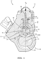
Figure 1 is a section of a high pressure pump provided with a shoe guide member. -
Figure 2 is a magnified area of the pump offigure 1 . -
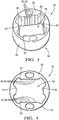
Figure 3 is a 3D view of a shoe guide member not part to the invention. -
Figure 4 is a top view of the shoe guide member offigure 3 . -
Figures 5-8 present a shoe guide member as per the invention. -
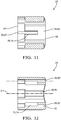
Figures 9-12 is an alternative not part to the invention. -
Figures 13-16 is another alternative not part to the invention. - In reference to the figures is now described a high
pressure diesel pump 10 adapted to be arranged in a diesel fuel injection equipment between an upstream low pressure delivery unit and a high pressure injection unit. Thepump 10 comprises apump body 12 on which is fixed a pumpinghead 14 wherein apiston 16, slidably arranged in abore 18 extending along a pumping axis X, performs a pumping cycle during which the volume of acontrol chamber 20 is varied. - The
pump body 12 further defines an inner space S wherein is arranged acamshaft 22 adapted to rotate about a camshaft axis Y1 perpendicular to the pumping axis X. - While the upper end of the piston remains inside the pumping
head 14 and directly contributes to the compression of the fuel in the compression chamber, an oppositelower end 24 of the piston protrudes outside the pumpinghead 14, and extends inside the inner space S for cooperating via a cam-follower 26 with acam 28 of thecamshaft 22. The cam-follower 26 is fixed to saidlower end 24 and is axially guided along the pumping axis X by aguide member 30 fixed to thepump body 12.
In use, thecam 28 rotates about the camshaft axis Y1 and it urges thepiston 16, via the cam-follower 26, to said reciprocal displacements forming the pumping cycle. - The use of relative terms such as upper or lower is done in relation to the arbitrary orientation of
figure 1 . It eases and clarifies the description and must not be interpreted as a limitation to the invention. - More precisely, the cam-
follower 26 comprises ashoe member 32 wherein is received acylindrical roller 34 adapted to rotate about a roller axis Y2 parallel to the camshaft axis Y1. In use, the outer cylindrical face of the roller rolls on the cam profile and imparts said axial X displacements to theshoe member 32 and to thepiston 16. - In a plan transverse to the pumping axis X, the
shoe member 32 has a rectangular cross-section and its shape is substantially circumscribed to a parallelepiped rectangle. Theshoe member 32 has a rectangular flatupper face 36 receiving in abutment thelower end 24 of the piston and, an opposedlower face 38 provided with a cylindricalconcave hollow 40 adjusted to complementary receive theroller 34. Between said upper 36 and lower 38 faces are defined four side faces comprising twolateral faces end faces - The cam-
follower 26 is axially X guided within theguide member 30, orshoe guide member 30 represented onfigures 3 and 4 . - The
shoe guide member 30 is a tubular member having a cylindricalouter face 50 extending along the pumping axis X between a transversetop face 52 and an opposedtransverse bottom face 54. Alternatively, other profiles such as rectangular are possible for theouter face 50. Theshoe guide 30 further defines a guidingbore 56 opening in saidtop 52 andbottom 54 faces, said guidingbore 56 defining four guidingfaces short faces - The guiding
bore 56 is adapted to complementary receive theshoe member 32, thelateral faces long faces bore 56 and, the end faces 46, 48, of the shoe member sliding against theshort faces - In a first example not part to the invention, as represented on
figure 3 , thelong faces bore 56 are provided with lubricant passages 65 which, in this first embodiment of the invention are vertical grooves 66 extending along the pumping axis X between thetop 52 andbottom face 54 of the shoe guide member. In the figure, five grooves 66 are represented but any other number is possible. Also, only one of the long face is visible but the grooves 66 are provided on bothlong faces - The grooves 66 represented have a triangular profile but other profiles, semi-circular, square, trapezoidal... are adequate as well. The grooves 66 intersect with the
long faces edge lines 68 and, to avoid stress concentration, saidedge lines 68 are rounded to provide a smooth transition between the face and the groove. - More small grooves well spread and arranged regularly across the
faces - In a non-represented alternative, the first and second short faces 62, 64, of the
shoe guide member 30 are also provided with grooves 66. - In a non-represented alternative embodiment, the faces of the guiding bore 56 are planar and the side faces 42, 44, of the shoe member are provided with grooves 66 having rounded edge lines 68.
- In another alternative, the end faces 46, 48, of the shoe member are also provided with grooves 66.
- In a further alternative embodiment, faces of both the
shoe member 32 and of theshoe guide member 30 are provided with grooves 66. - An embodiment of the
shoe guide member 30 as per the invention is now described onfigures 5-8 by way of differences to the first example. - The lubricant passages 65 are conduits 67, or drillings, arranged in the body of the
shoe guide member 30 where they extend from alower opening 70 in thebottom face 54 of the shoe guide member to an upper, or side, opening 72 in saidlong faces - In the embodiment of
figures 5-8 , the conduits 67 makes an angle A with the pumping axis X, said angle A being quite small of few degrees, the conduit 67 is not exactly perpendicular to saidbottom face 54 of the shoe guide member. Therefore, thelower opening 70 of the conduit is slightly elliptical and is provided in the largest part of saidbottom face 54, where the guiding face is the most distant from the cylindricalouter face 50 of the shoe guide member. More precisely, as visible onfigure 5 thelower opening 70 is arranged on the median plane of the guiding faces 58, 60, equidistant between saidouter face 50 and said guidingface lower opening 70, the conduit 67 extends in said median plane to theupper opening 72 that defines in the upper portion of the guidingface 58, 60 a long elliptical notch. - To the contrary of the first example where a large number of small grooves 66 is preferred to reach the same objective of improved lubrication of the guiding faces, this embodiment prefers a unique conduit 67 which long notch defined by the
upper opening 72 extends on substantially the upper half height of said face. - In the alternative of
figures 9-12 not part to the invention the conduit 67 is drilled aligned to the pumping axis X, therefore parallel to the guidingface lower opening 70, which now forms an exact circle in thebottom face 54, to thetop face 56 of the shoe guide member. A rectangular aperture 74 is formed joining the upper half of the guiding face to the conduit 67 and enabling, in use, lubricant fluid to flow along said guiding face. - In an alternative not part to the invention presented on
figures 13-16 , the conduit 67 is drilled aligned to the pumping axis X, similarly to the previous alternative but, instead of having a circular section the conduit's section is oblong, with long axis parallel to the guiding face. -
- X
- pumping axis
- Y1
- camshaft axis
- Y2
- roller axis
- S
- inner space
- C
- clearance
- 10
- pump
- 12
- pump body
- 14
- pumping head
- 16
- piston
- 18
- bore
- 20
- control chamber
- 22
- camshaft
- 24
- lower end of the piston
- 26
- cam-follower
- 28
- cam
- 30
- shoe guide member
- 32
- shoe member
- 34
- roller
- 36
- upper face of the shoe member
- 38
- lower face of the shoe member
- 40
- concave hollow
- 42
- side face of the shoe member - lateral face
- 44
- side face of the shoe member - lateral face
- 46
- side face of the shoe member - end face
- 48
- side face of the shoe member - end face
- 50
- outer face of the shoe guide member
- 52
- top face of the shoe guide member
- 54
- bottom face of the shoe guide member
- 56
- guiding bore
- 58
- guiding face of the guiding bore - first long face
- 60
- guiding face of the guiding bore - second long face
- 62
- guiding face of the guiding bore - first short face
- 64
- guiding face of the guiding bore - second short face
- 65
- lubricant passage
- 66
- groove
- 67
- conduit
- 68
- edge lines of the groove
- 70
- side opening
- 72
- upper opening of the conduit in the guiding face - long notch
- 74
- rectangular opening
Claims (12)
- Shoe guide member (30) of a high pressure fuel pump (10), the shoe guide member (30) being provided with a guiding bore (56) extending along a pumping axis (X) and opening in a top face (52) and in a bottom face (54) of the shoe guide member, said guiding bore (56) defining two long faces (58, 60) parallel to each other and perpendicular to two short faces (62, 64) against which, in use, slide faces (42, 44, 46, 48) of a shoe member and,
wherein the shoe guide member (30) is further provided with at least one passage (65, 66) extending from said top (52) to said bottom (54) face and enabling, in use, lubricant fluid to flow between said top and bottom faces,
characterized in that
said passages (65) are conduits (67) arranged in the shoe guide member and angled relative to the pumping axis (X), said conduits (67) opening at a first end in the bottom face (54) at a distance from the long faces (58, 60) and, at a second end in the vicinity of the top face (52) in the long face (58, 60) so that the area of said long faces (58, 60) closer to the bottom face (54) is larger than the area closer to the top face (52). - Shoe guide member (30) as claimed in the preceding claim wherein said passages (65) are a plurality of grooves (66) arranged in each of the long face (58, 60).
- Shoe guide member (30) as claimed in claim 2 further comprising a plurality of said grooves (66) in each of the lateral guiding face.
- Shoe guide member (30) as claimed in any one of the claims 2 or 3 wherein the guiding bore (56) defines a pumping axis (X), the groove (66) being aligned with said pumping axis (X).
- Shoe guide member (30) as claimed in claim 4 when depending upon claim 3 wherein said plurality of grooves (66) are parallel to each other.
- Shoe guide member (30) as claimed in claim 5 wherein said plurality of grooves (66) are distributed across said guiding faces.
- Shoe guide member (30) as claimed in any one of the preceding claims wherein said groove (66) intersects with said guiding face along edge lines (68) which are rounded and smooth so that, stress concentration is avoided.
- Shoe guide member (30) as claimed in claim 1 wherein two conduits (67) are provided, one close to each of the long faces (58, 60).
- Shoe guide member (30) as claimed in any one of the claims 1 or 8 wherein said conduit (67) is drilled at an angle (A) relative to the long faces (58, 60), said angular drilling enabling a lower opening (70) distant from the face and an upper opening (72) in the long face.
- Shoe guide member (30) as claimed in any one of the claims 1 or 8 wherein said conduit (67) is drilled parallel to and from distant the long face, the shoe guide member being further provided with a side opening (74) joining the conduit (67) to said long face (58, 60), said side opening (74) being limited to a region of said long face in the vicinity to the top face (52).
- Shoe member (32) of a high pressure fuel pump (10), the shoe member (32) being adapted to be slidably guided within the guiding bore (56) provided in a shoe guide member (30) as claimed in any of the preceding claims.
- High pressure fuel pump (10) comprising a shoe guide member (30) as claimed in any one of the claims 1 to 10.
Applications Claiming Priority (2)
| Application Number | Priority Date | Filing Date | Title |
|---|---|---|---|
| GB1610181.8A GB2551203B (en) | 2016-06-10 | 2016-06-10 | Guiding arangement of high pressure pump |
| PCT/EP2017/058417 WO2017211480A1 (en) | 2016-06-10 | 2017-04-07 | Guiding arrangement of high pressure pump |
Publications (2)
| Publication Number | Publication Date |
|---|---|
| EP3469214A1 EP3469214A1 (en) | 2019-04-17 |
| EP3469214B1 true EP3469214B1 (en) | 2021-03-03 |
Family
ID=56894859
Family Applications (1)
| Application Number | Title | Priority Date | Filing Date |
|---|---|---|---|
| EP17717126.1A Active EP3469214B1 (en) | 2016-06-10 | 2017-04-07 | Guiding arrangement of high pressure pump |
Country Status (3)
| Country | Link |
|---|---|
| EP (1) | EP3469214B1 (en) |
| GB (1) | GB2551203B (en) |
| WO (1) | WO2017211480A1 (en) |
Families Citing this family (1)
| Publication number | Priority date | Publication date | Assignee | Title |
|---|---|---|---|---|
| CN111140589B (en) * | 2019-12-29 | 2020-12-18 | 陕西航天动力高科技股份有限公司 | Lubrication structure of a crosshead assembly for a diaphragm pump |
Family Cites Families (9)
| Publication number | Priority date | Publication date | Assignee | Title |
|---|---|---|---|---|
| DE4225363A1 (en) * | 1992-07-31 | 1994-02-03 | Bosch Gmbh Robert | Fuel injection pump for internal combustion engines |
| DE102006031032A1 (en) * | 2006-07-05 | 2008-01-10 | Schaeffler Kg | Tappet for fuel high pressure pump of internal combustion engine, has cross-hole for supplying lubricant to shell surface and bearing surface, and tappet skirt with outer annular groove that connects cross hole with lubricant supply channel |
| JP2010249101A (en) * | 2009-04-20 | 2010-11-04 | Yanmar Co Ltd | Fuel injection pump |
| DE102010042488A1 (en) * | 2010-10-15 | 2012-04-19 | Robert Bosch Gmbh | High pressure pump for e.g. common-rail injection system of diesel engine, has plunger space held in fluid connection with pumping space via longitudinal grooves, and plunger body moveably fed in pump casing |
| DE102010042509A1 (en) * | 2010-10-15 | 2012-04-19 | Robert Bosch Gmbh | Roller shoe for a high pressure pump of a fuel injection system |
| JP5516347B2 (en) * | 2010-11-12 | 2014-06-11 | 株式会社デンソー | Fuel supply pump |
| HUE025332T2 (en) * | 2012-04-25 | 2016-02-29 | Delphi Int Operations Luxembourg Sarl | High pressure fuel pump assembly |
| DE102014220750A1 (en) * | 2014-10-14 | 2016-04-14 | Continental Automotive Gmbh | High-pressure pump for a fuel injection system of an internal combustion engine and arrangement of high pressure pump and engine block |
| GB201505089D0 (en) * | 2015-03-26 | 2015-05-06 | Delphi International Operations Luxembourg S.�.R.L. | An oil lubricated common rail diesel pump |
-
2016
- 2016-06-10 GB GB1610181.8A patent/GB2551203B/en active Active
-
2017
- 2017-04-07 EP EP17717126.1A patent/EP3469214B1/en active Active
- 2017-04-07 WO PCT/EP2017/058417 patent/WO2017211480A1/en not_active Ceased
Non-Patent Citations (1)
| Title |
|---|
| None * |
Also Published As
| Publication number | Publication date |
|---|---|
| GB2551203B (en) | 2020-03-18 |
| GB201610181D0 (en) | 2016-07-27 |
| GB2551203A (en) | 2017-12-13 |
| EP3469214A1 (en) | 2019-04-17 |
| WO2017211480A1 (en) | 2017-12-14 |
Similar Documents
| Publication | Publication Date | Title |
|---|---|---|
| EP2657505B1 (en) | High pressure fuel pump assembly | |
| WO2016103554A1 (en) | Variable length connecting rod and variable compression ratio internal combustion engine | |
| EP3187729B1 (en) | Fluted piston components for pumps | |
| KR101242826B1 (en) | Variable capacity hydraulic pump motor | |
| JP6401509B2 (en) | Piston pump and piston pump valve plate | |
| US20070041848A1 (en) | Pump assembly | |
| US9022755B2 (en) | Volumetric pump and its driving mechanism | |
| CN104612958A (en) | A pump | |
| US11053929B2 (en) | Variable displacement pump | |
| KR102215870B1 (en) | High pressure pump | |
| JP2016017430A (en) | Hydraulic rotating machine | |
| JP2009531590A (en) | Hydraulic piston machine with rotatable cam disk | |
| KR20140048896A (en) | Linear actuator | |
| JP6466282B2 (en) | Regulator of variable capacity hydraulic rotating machine | |
| EP3469214A1 (en) | Guiding arrangement of high pressure pump | |
| EP2628942A1 (en) | Pump and common rail fuel injection system | |
| EP2489876B1 (en) | Piston-to-shoe interface lubrication method | |
| KR101110740B1 (en) | Apparatus of Piston and Eccentric Cam for Radial Piston Pump | |
| US10465667B2 (en) | Variable displacement pump | |
| FR3066571B1 (en) | HYDRAULIC DAMPING SYSTEM INCLUDING A VARIABLE INERTIAL MASS OF FLUID | |
| EP3368766B1 (en) | High pressure fuel pump | |
| US10690124B2 (en) | Axial piston hydraulic pump | |
| CN109891093A (en) | Cylinder block and swash plate type hydraulic rotary device provided with same | |
| US20180112776A1 (en) | Seals separated by retaining clip | |
| DE102015223037A1 (en) | Vibratory drive with hydraulic pulse generating device |
Legal Events
| Date | Code | Title | Description |
|---|---|---|---|
| STAA | Information on the status of an ep patent application or granted ep patent |
Free format text: STATUS: UNKNOWN |
|
| STAA | Information on the status of an ep patent application or granted ep patent |
Free format text: STATUS: THE INTERNATIONAL PUBLICATION HAS BEEN MADE |
|
| PUAI | Public reference made under article 153(3) epc to a published international application that has entered the european phase |
Free format text: ORIGINAL CODE: 0009012 |
|
| STAA | Information on the status of an ep patent application or granted ep patent |
Free format text: STATUS: REQUEST FOR EXAMINATION WAS MADE |
|
| 17P | Request for examination filed |
Effective date: 20190110 |
|
| AK | Designated contracting states |
Kind code of ref document: A1 Designated state(s): AL AT BE BG CH CY CZ DE DK EE ES FI FR GB GR HR HU IE IS IT LI LT LU LV MC MK MT NL NO PL PT RO RS SE SI SK SM TR |
|
| AX | Request for extension of the european patent |
Extension state: BA ME |
|
| DAV | Request for validation of the european patent (deleted) | ||
| DAX | Request for extension of the european patent (deleted) | ||
| STAA | Information on the status of an ep patent application or granted ep patent |
Free format text: STATUS: EXAMINATION IS IN PROGRESS |
|
| 17Q | First examination report despatched |
Effective date: 20200221 |
|
| GRAP | Despatch of communication of intention to grant a patent |
Free format text: ORIGINAL CODE: EPIDOSNIGR1 |
|
| STAA | Information on the status of an ep patent application or granted ep patent |
Free format text: STATUS: GRANT OF PATENT IS INTENDED |
|
| INTG | Intention to grant announced |
Effective date: 20200930 |
|
| GRAS | Grant fee paid |
Free format text: ORIGINAL CODE: EPIDOSNIGR3 |
|
| GRAA | (expected) grant |
Free format text: ORIGINAL CODE: 0009210 |
|
| STAA | Information on the status of an ep patent application or granted ep patent |
Free format text: STATUS: THE PATENT HAS BEEN GRANTED |
|
| AK | Designated contracting states |
Kind code of ref document: B1 Designated state(s): AL AT BE BG CH CY CZ DE DK EE ES FI FR GB GR HR HU IE IS IT LI LT LU LV MC MK MT NL NO PL PT RO RS SE SI SK SM TR |
|
| REG | Reference to a national code |
Ref country code: GB Ref legal event code: FG4D |
|
| REG | Reference to a national code |
Ref country code: AT Ref legal event code: REF Ref document number: 1367480 Country of ref document: AT Kind code of ref document: T Effective date: 20210315 Ref country code: CH Ref legal event code: EP |
|
| REG | Reference to a national code |
Ref country code: DE Ref legal event code: R096 Ref document number: 602017033771 Country of ref document: DE |
|
| REG | Reference to a national code |
Ref country code: IE Ref legal event code: FG4D |
|
| REG | Reference to a national code |
Ref country code: LT Ref legal event code: MG9D |
|
| PG25 | Lapsed in a contracting state [announced via postgrant information from national office to epo] |
Ref country code: LT Free format text: LAPSE BECAUSE OF FAILURE TO SUBMIT A TRANSLATION OF THE DESCRIPTION OR TO PAY THE FEE WITHIN THE PRESCRIBED TIME-LIMIT Effective date: 20210303 Ref country code: BG Free format text: LAPSE BECAUSE OF FAILURE TO SUBMIT A TRANSLATION OF THE DESCRIPTION OR TO PAY THE FEE WITHIN THE PRESCRIBED TIME-LIMIT Effective date: 20210603 Ref country code: HR Free format text: LAPSE BECAUSE OF FAILURE TO SUBMIT A TRANSLATION OF THE DESCRIPTION OR TO PAY THE FEE WITHIN THE PRESCRIBED TIME-LIMIT Effective date: 20210303 Ref country code: GR Free format text: LAPSE BECAUSE OF FAILURE TO SUBMIT A TRANSLATION OF THE DESCRIPTION OR TO PAY THE FEE WITHIN THE PRESCRIBED TIME-LIMIT Effective date: 20210604 Ref country code: FI Free format text: LAPSE BECAUSE OF FAILURE TO SUBMIT A TRANSLATION OF THE DESCRIPTION OR TO PAY THE FEE WITHIN THE PRESCRIBED TIME-LIMIT Effective date: 20210303 Ref country code: NO Free format text: LAPSE BECAUSE OF FAILURE TO SUBMIT A TRANSLATION OF THE DESCRIPTION OR TO PAY THE FEE WITHIN THE PRESCRIBED TIME-LIMIT Effective date: 20210603 |
|
| REG | Reference to a national code |
Ref country code: NL Ref legal event code: MP Effective date: 20210303 |
|
| REG | Reference to a national code |
Ref country code: AT Ref legal event code: MK05 Ref document number: 1367480 Country of ref document: AT Kind code of ref document: T Effective date: 20210303 |
|
| PG25 | Lapsed in a contracting state [announced via postgrant information from national office to epo] |
Ref country code: LV Free format text: LAPSE BECAUSE OF FAILURE TO SUBMIT A TRANSLATION OF THE DESCRIPTION OR TO PAY THE FEE WITHIN THE PRESCRIBED TIME-LIMIT Effective date: 20210303 Ref country code: PL Free format text: LAPSE BECAUSE OF FAILURE TO SUBMIT A TRANSLATION OF THE DESCRIPTION OR TO PAY THE FEE WITHIN THE PRESCRIBED TIME-LIMIT Effective date: 20210303 Ref country code: RS Free format text: LAPSE BECAUSE OF FAILURE TO SUBMIT A TRANSLATION OF THE DESCRIPTION OR TO PAY THE FEE WITHIN THE PRESCRIBED TIME-LIMIT Effective date: 20210303 Ref country code: SE Free format text: LAPSE BECAUSE OF FAILURE TO SUBMIT A TRANSLATION OF THE DESCRIPTION OR TO PAY THE FEE WITHIN THE PRESCRIBED TIME-LIMIT Effective date: 20210303 |
|
| PG25 | Lapsed in a contracting state [announced via postgrant information from national office to epo] |
Ref country code: NL Free format text: LAPSE BECAUSE OF FAILURE TO SUBMIT A TRANSLATION OF THE DESCRIPTION OR TO PAY THE FEE WITHIN THE PRESCRIBED TIME-LIMIT Effective date: 20210303 |
|
| PG25 | Lapsed in a contracting state [announced via postgrant information from national office to epo] |
Ref country code: EE Free format text: LAPSE BECAUSE OF FAILURE TO SUBMIT A TRANSLATION OF THE DESCRIPTION OR TO PAY THE FEE WITHIN THE PRESCRIBED TIME-LIMIT Effective date: 20210303 Ref country code: CZ Free format text: LAPSE BECAUSE OF FAILURE TO SUBMIT A TRANSLATION OF THE DESCRIPTION OR TO PAY THE FEE WITHIN THE PRESCRIBED TIME-LIMIT Effective date: 20210303 Ref country code: AT Free format text: LAPSE BECAUSE OF FAILURE TO SUBMIT A TRANSLATION OF THE DESCRIPTION OR TO PAY THE FEE WITHIN THE PRESCRIBED TIME-LIMIT Effective date: 20210303 Ref country code: SM Free format text: LAPSE BECAUSE OF FAILURE TO SUBMIT A TRANSLATION OF THE DESCRIPTION OR TO PAY THE FEE WITHIN THE PRESCRIBED TIME-LIMIT Effective date: 20210303 |
|
| PG25 | Lapsed in a contracting state [announced via postgrant information from national office to epo] |
Ref country code: IS Free format text: LAPSE BECAUSE OF FAILURE TO SUBMIT A TRANSLATION OF THE DESCRIPTION OR TO PAY THE FEE WITHIN THE PRESCRIBED TIME-LIMIT Effective date: 20210703 Ref country code: RO Free format text: LAPSE BECAUSE OF FAILURE TO SUBMIT A TRANSLATION OF THE DESCRIPTION OR TO PAY THE FEE WITHIN THE PRESCRIBED TIME-LIMIT Effective date: 20210303 Ref country code: SK Free format text: LAPSE BECAUSE OF FAILURE TO SUBMIT A TRANSLATION OF THE DESCRIPTION OR TO PAY THE FEE WITHIN THE PRESCRIBED TIME-LIMIT Effective date: 20210303 Ref country code: PT Free format text: LAPSE BECAUSE OF FAILURE TO SUBMIT A TRANSLATION OF THE DESCRIPTION OR TO PAY THE FEE WITHIN THE PRESCRIBED TIME-LIMIT Effective date: 20210705 |
|
| REG | Reference to a national code |
Ref country code: DE Ref legal event code: R097 Ref document number: 602017033771 Country of ref document: DE |
|
| PG25 | Lapsed in a contracting state [announced via postgrant information from national office to epo] |
Ref country code: LU Free format text: LAPSE BECAUSE OF NON-PAYMENT OF DUE FEES Effective date: 20210407 |
|
| PLBE | No opposition filed within time limit |
Free format text: ORIGINAL CODE: 0009261 |
|
| STAA | Information on the status of an ep patent application or granted ep patent |
Free format text: STATUS: NO OPPOSITION FILED WITHIN TIME LIMIT |
|
| REG | Reference to a national code |
Ref country code: BE Ref legal event code: MM Effective date: 20210430 |
|
| PG25 | Lapsed in a contracting state [announced via postgrant information from national office to epo] |
Ref country code: LI Free format text: LAPSE BECAUSE OF NON-PAYMENT OF DUE FEES Effective date: 20210430 Ref country code: MC Free format text: LAPSE BECAUSE OF FAILURE TO SUBMIT A TRANSLATION OF THE DESCRIPTION OR TO PAY THE FEE WITHIN THE PRESCRIBED TIME-LIMIT Effective date: 20210303 Ref country code: DK Free format text: LAPSE BECAUSE OF FAILURE TO SUBMIT A TRANSLATION OF THE DESCRIPTION OR TO PAY THE FEE WITHIN THE PRESCRIBED TIME-LIMIT Effective date: 20210303 Ref country code: CH Free format text: LAPSE BECAUSE OF NON-PAYMENT OF DUE FEES Effective date: 20210430 Ref country code: AL Free format text: LAPSE BECAUSE OF FAILURE TO SUBMIT A TRANSLATION OF THE DESCRIPTION OR TO PAY THE FEE WITHIN THE PRESCRIBED TIME-LIMIT Effective date: 20210303 Ref country code: ES Free format text: LAPSE BECAUSE OF FAILURE TO SUBMIT A TRANSLATION OF THE DESCRIPTION OR TO PAY THE FEE WITHIN THE PRESCRIBED TIME-LIMIT Effective date: 20210303 |
|
| 26N | No opposition filed |
Effective date: 20211206 |
|
| GBPC | Gb: european patent ceased through non-payment of renewal fee |
Effective date: 20210603 |
|
| PG25 | Lapsed in a contracting state [announced via postgrant information from national office to epo] |
Ref country code: SI Free format text: LAPSE BECAUSE OF FAILURE TO SUBMIT A TRANSLATION OF THE DESCRIPTION OR TO PAY THE FEE WITHIN THE PRESCRIBED TIME-LIMIT Effective date: 20210303 |
|
| PG25 | Lapsed in a contracting state [announced via postgrant information from national office to epo] |
Ref country code: IT Free format text: LAPSE BECAUSE OF FAILURE TO SUBMIT A TRANSLATION OF THE DESCRIPTION OR TO PAY THE FEE WITHIN THE PRESCRIBED TIME-LIMIT Effective date: 20210303 Ref country code: IE Free format text: LAPSE BECAUSE OF NON-PAYMENT OF DUE FEES Effective date: 20210407 Ref country code: GB Free format text: LAPSE BECAUSE OF NON-PAYMENT OF DUE FEES Effective date: 20210603 |
|
| PG25 | Lapsed in a contracting state [announced via postgrant information from national office to epo] |
Ref country code: IS Free format text: LAPSE BECAUSE OF FAILURE TO SUBMIT A TRANSLATION OF THE DESCRIPTION OR TO PAY THE FEE WITHIN THE PRESCRIBED TIME-LIMIT Effective date: 20210703 |
|
| PG25 | Lapsed in a contracting state [announced via postgrant information from national office to epo] |
Ref country code: BE Free format text: LAPSE BECAUSE OF NON-PAYMENT OF DUE FEES Effective date: 20210430 |
|
| P01 | Opt-out of the competence of the unified patent court (upc) registered |
Effective date: 20230327 |
|
| PG25 | Lapsed in a contracting state [announced via postgrant information from national office to epo] |
Ref country code: CY Free format text: LAPSE BECAUSE OF FAILURE TO SUBMIT A TRANSLATION OF THE DESCRIPTION OR TO PAY THE FEE WITHIN THE PRESCRIBED TIME-LIMIT Effective date: 20210303 |
|
| PG25 | Lapsed in a contracting state [announced via postgrant information from national office to epo] |
Ref country code: HU Free format text: LAPSE BECAUSE OF FAILURE TO SUBMIT A TRANSLATION OF THE DESCRIPTION OR TO PAY THE FEE WITHIN THE PRESCRIBED TIME-LIMIT; INVALID AB INITIO Effective date: 20170407 |
|
| REG | Reference to a national code |
Ref country code: DE Ref legal event code: R081 Ref document number: 602017033771 Country of ref document: DE Owner name: PHINIA DELPHI LUXEMBOURG SARL, LU Free format text: FORMER OWNER: DELPHI TECHNOLOGIES IP LIMITED, SAINT MICHAEL, BB |
|
| PG25 | Lapsed in a contracting state [announced via postgrant information from national office to epo] |
Ref country code: MK Free format text: LAPSE BECAUSE OF FAILURE TO SUBMIT A TRANSLATION OF THE DESCRIPTION OR TO PAY THE FEE WITHIN THE PRESCRIBED TIME-LIMIT Effective date: 20210303 |
|
| PG25 | Lapsed in a contracting state [announced via postgrant information from national office to epo] |
Ref country code: MT Free format text: LAPSE BECAUSE OF FAILURE TO SUBMIT A TRANSLATION OF THE DESCRIPTION OR TO PAY THE FEE WITHIN THE PRESCRIBED TIME-LIMIT Effective date: 20210303 |
|
| PGFP | Annual fee paid to national office [announced via postgrant information from national office to epo] |
Ref country code: DE Payment date: 20250317 Year of fee payment: 9 |
|
| PG25 | Lapsed in a contracting state [announced via postgrant information from national office to epo] |
Ref country code: TR Free format text: LAPSE BECAUSE OF FAILURE TO SUBMIT A TRANSLATION OF THE DESCRIPTION OR TO PAY THE FEE WITHIN THE PRESCRIBED TIME-LIMIT Effective date: 20210303 |
|
| PGFP | Annual fee paid to national office [announced via postgrant information from national office to epo] |
Ref country code: FR Payment date: 20260317 Year of fee payment: 10 |