EP3467932A1 - Zinc cell and zinc flow cell - Google Patents
Zinc cell and zinc flow cell Download PDFInfo
- Publication number
- EP3467932A1 EP3467932A1 EP17806654.4A EP17806654A EP3467932A1 EP 3467932 A1 EP3467932 A1 EP 3467932A1 EP 17806654 A EP17806654 A EP 17806654A EP 3467932 A1 EP3467932 A1 EP 3467932A1
- Authority
- EP
- European Patent Office
- Prior art keywords
- zinc
- electrolytic solution
- negative electrode
- powder
- positive electrode
- Prior art date
- Legal status (The legal status is an assumption and is not a legal conclusion. Google has not performed a legal analysis and makes no representation as to the accuracy of the status listed.)
- Withdrawn
Links
Images



Classifications
-
- H—ELECTRICITY
- H01—ELECTRIC ELEMENTS
- H01M—PROCESSES OR MEANS, e.g. BATTERIES, FOR THE DIRECT CONVERSION OF CHEMICAL ENERGY INTO ELECTRICAL ENERGY
- H01M8/00—Fuel cells; Manufacture thereof
- H01M8/18—Regenerative fuel cells, e.g. redox flow batteries or secondary fuel cells
- H01M8/184—Regeneration by electrochemical means
- H01M8/188—Regeneration by electrochemical means by recharging of redox couples containing fluids; Redox flow type batteries
-
- H—ELECTRICITY
- H01—ELECTRIC ELEMENTS
- H01M—PROCESSES OR MEANS, e.g. BATTERIES, FOR THE DIRECT CONVERSION OF CHEMICAL ENERGY INTO ELECTRICAL ENERGY
- H01M10/00—Secondary cells; Manufacture thereof
- H01M10/24—Alkaline accumulators
- H01M10/26—Selection of materials as electrolytes
-
- H—ELECTRICITY
- H01—ELECTRIC ELEMENTS
- H01M—PROCESSES OR MEANS, e.g. BATTERIES, FOR THE DIRECT CONVERSION OF CHEMICAL ENERGY INTO ELECTRICAL ENERGY
- H01M50/00—Constructional details or processes of manufacture of the non-active parts of electrochemical cells other than fuel cells, e.g. hybrid cells
- H01M50/70—Arrangements for stirring or circulating the electrolyte
-
- H—ELECTRICITY
- H01—ELECTRIC ELEMENTS
- H01M—PROCESSES OR MEANS, e.g. BATTERIES, FOR THE DIRECT CONVERSION OF CHEMICAL ENERGY INTO ELECTRICAL ENERGY
- H01M50/00—Constructional details or processes of manufacture of the non-active parts of electrochemical cells other than fuel cells, e.g. hybrid cells
- H01M50/70—Arrangements for stirring or circulating the electrolyte
- H01M50/77—Arrangements for stirring or circulating the electrolyte with external circulating path
-
- Y—GENERAL TAGGING OF NEW TECHNOLOGICAL DEVELOPMENTS; GENERAL TAGGING OF CROSS-SECTIONAL TECHNOLOGIES SPANNING OVER SEVERAL SECTIONS OF THE IPC; TECHNICAL SUBJECTS COVERED BY FORMER USPC CROSS-REFERENCE ART COLLECTIONS [XRACs] AND DIGESTS
- Y02—TECHNOLOGIES OR APPLICATIONS FOR MITIGATION OR ADAPTATION AGAINST CLIMATE CHANGE
- Y02E—REDUCTION OF GREENHOUSE GAS [GHG] EMISSIONS, RELATED TO ENERGY GENERATION, TRANSMISSION OR DISTRIBUTION
- Y02E60/00—Enabling technologies; Technologies with a potential or indirect contribution to GHG emissions mitigation
- Y02E60/10—Energy storage using batteries
-
- Y—GENERAL TAGGING OF NEW TECHNOLOGICAL DEVELOPMENTS; GENERAL TAGGING OF CROSS-SECTIONAL TECHNOLOGIES SPANNING OVER SEVERAL SECTIONS OF THE IPC; TECHNICAL SUBJECTS COVERED BY FORMER USPC CROSS-REFERENCE ART COLLECTIONS [XRACs] AND DIGESTS
- Y02—TECHNOLOGIES OR APPLICATIONS FOR MITIGATION OR ADAPTATION AGAINST CLIMATE CHANGE
- Y02E—REDUCTION OF GREENHOUSE GAS [GHG] EMISSIONS, RELATED TO ENERGY GENERATION, TRANSMISSION OR DISTRIBUTION
- Y02E60/00—Enabling technologies; Technologies with a potential or indirect contribution to GHG emissions mitigation
- Y02E60/30—Hydrogen technology
- Y02E60/50—Fuel cells
-
- Y—GENERAL TAGGING OF NEW TECHNOLOGICAL DEVELOPMENTS; GENERAL TAGGING OF CROSS-SECTIONAL TECHNOLOGIES SPANNING OVER SEVERAL SECTIONS OF THE IPC; TECHNICAL SUBJECTS COVERED BY FORMER USPC CROSS-REFERENCE ART COLLECTIONS [XRACs] AND DIGESTS
- Y02—TECHNOLOGIES OR APPLICATIONS FOR MITIGATION OR ADAPTATION AGAINST CLIMATE CHANGE
- Y02P—CLIMATE CHANGE MITIGATION TECHNOLOGIES IN THE PRODUCTION OR PROCESSING OF GOODS
- Y02P70/00—Climate change mitigation technologies in the production process for final industrial or consumer products
- Y02P70/50—Manufacturing or production processes characterised by the final manufactured product
Definitions
- Embodiments disclosed herein relate to a zinc battery and a zinc flow battery.
- Patent Literature 1 a technique for reducing growth of dendrite by covering a negative electrode including an active material, such as a zinc species, with an ion conductive layer having selective ion conductivity has been proposed (as seen in, for example, Patent Literature 1).
- Patent Literature 1 Japanese Patent Application Laid-open No. 2015-185259
- Non-Patent Literature 1 Y. Ito., et al.: Zinc Morphology in Zinc-Nickel Flow Assisted Batteries and Impact on Performance, Journal of Power Sources, Vol. 196, pp. 2340-2345, 2011
- a zinc battery includes a negative electrode and a positive electrode, an electrolytic solution, and a powder.
- the electrolytic solution contacts with the negative electrode and the positive electrode.
- the powder includes zinc and mixed in the electrolytic solution.
- FIG. 1 is a diagram illustrating an outline of a zinc battery according to a first embodiment.
- a zinc battery 1 illustrated in FIG. 1 includes a negative electrode 2, a positive electrode 3, a porous body 4, a coating 5, an electrolytic solution 6, a powder 7, a case 8, and an upper plate 9.
- FIG. 1 illustrates a three-dimensional rectangular coordinate system including a Z-axis having a positive direction vertically upward and a negative direction vertically downward.
- This rectangular coordinate system may be illustrated in any other drawing used in the description later.
- the negative electrode 2 includes a negative electrode active material as metal.
- a metal plate made of stainless steel, copper, or the like, or a stainless steel or copper plate having a surface that has been plated with nickel, tin, or zinc, may be used as the negative electrode 2.
- a metal plate having a plated surface that has been partially oxidized may be used as the negative electrode 2.
- the positive electrode 3 is an electrically conductive member containing, for example, a nickel compound, a manganese compound, or a cobalt compound, which serves as a positive electrode active material.
- the nickel compound is preferably, for example, nickel oxyhydroxide, nickel hydroxide, or cobalt-containing nickel hydroxide.
- the manganese compound is preferably, for example, manganese dioxide.
- the cobalt compound is preferably, for example, cobalt hydroxide or cobalt oxyhydroxide.
- the positive electrode 3 may include graphite, carbon black, an electrically conductive resin, or the like. In terms of oxidation-reduction potential for decomposition of the electrolytic solution 6, the positive electrode 3 preferably contains the nickel compound.
- the electrolytic solution 6 is an alkali aqueous solution containing a zinc species.
- the zinc species in the electrolytic solution 6 is dissolved in the electrolytic solution as [Zn(OH) 4 ] 2- .
- an alkali aqueous solution containing K + and OH - and saturated with the zinc species may be used as the electrolytic solution 6.
- the electrolytic solution 6 is preferably prepared, together with the powder 7, which will be described later.
- a 6.7 moldm -3 aqueous potassium hydroxide solution may be used as the alkali aqueous solution.
- the electrolytic solution 6 may be prepared by addition of ZnO into the aqueous potassium hydroxide solution at a ratio of 0.5 mol to 1 dm -3 , and as necessary, addition of the powder 7 described later.
- the powder 7 includes zinc.
- the powder 7 is, for example, zinc oxide or zinc hydroxide, which has been processed into or formed as powder.
- the powder 7 easily dissolves in an alkali aqueous solution, but settles out without dissolving in the electrolytic solution 6 saturated with the zinc species, and some of the powder 7 is also mixed in the electrolytic solution 6 in a dispersed or floating state. If the electrolytic solution 6 has been left to stand for a long period of time, most of the powder 7 may have settled out, but if convection or the like is caused in the electrolytic solution 6, some of the powder 7 that has settled out will be in a state dispersed or floating in the electrolytic solution 6. In other words, the powder 7 exists movably in the electrolytic solution 6.
- Being movable herein does not mean that a part of the powder 7 is able to move only in a local space formed in another part of the powder 7 surrounding that part of the powder 7, but means that by moving in the electrolytic solution 6 from an initial position to a different position, the powder 7 is exposed to the electrolytic solution 6 that is not at the initial position. Further, the meaning of being movable includes that the powder 7 is able to move to the vicinity of both the negative electrode 2 and positive electrode 3, and that the powder 7 is able to move to almost anywhere in the electrolytic solution 6 that is in the case 8.
- Electrode reactions in a nickel-zinc battery which is an example of the zinc battery 1, will be described, the nickel-zinc battery having nickel hydroxide used therein as a positive electrode active material.
- Reaction formulae for the positive electrode 3 and the negative electrode 2 upon battery charging are respectively as follows.
- the zinc battery 1 has the powder 7 including zinc, mixed also in the electrolytic solution 6.
- [Zn(OH) 4 ] 2- in the electrolytic solution 6 is consumed by battery charging, [Zn(OH) 4 ] 2- is resupplied in the electrolytic solution 6 by dissolution of zinc in the powder 7 in accordance with the consumption. Therefore, the concentration of [Zn(OH) 4 ] 2- in the electrolytic solution 6 is able to be maintained in the saturated state, and electric conduction between the negative electrode 2 and the positive electrode 3 associated with the growth of dendrite is thus able to be reduced.
- Examples of the powder 7 include, in addition to zinc oxide and zinc hydroxide: metallic zinc; calcium zincate; zinc carbonate; zinc sulfate; and zinc chloride, where zinc oxide and zinc hydroxide are preferable.
- Zn is consumed and [Zn(OH) 4 ] 2- is generated by electric discharge at the negative electrode 2, but since the electrolytic solution 6 is already in the saturated state, ZnO is deposited in the electrolytic solution 6 from [Zn(OH) 4 ] 2- that has become excessive.
- Zinc consumed at the negative electrode 2 upon the electric discharge is zinc that has been deposited on the surface of the negative electrode 2 upon battery charging. Therefore, differently from a case where charging and discharging are basically repeated by use of a negative electrode containing a zinc species, so-called shape change where the surface shape of the negative electrode 2 changes is not caused. Thereby, the zinc battery 1 according to the first embodiment enables reduction of time degradation of the negative electrode 2.
- Zn(OH) 2 , or a mixture of ZnO and Zn(OH) 2 may be deposited from [Zn(OH) 4 ] 2- that has become excessive.
- the porous body 4 covers the negative electrode 2.
- the porous body 4 is formed of a material having electric conductivity, for example, carbon felt.
- the reaction field between the electrolytic solution 6 and the negative electrode 2 is enlarged, the reaction rate upon charging and discharging is improved, and the generation of dendrite associated with centralization of the reaction field is reduced. Further, the electrolytic solution 6 is diffused over the whole surface of the negative electrode 2 via voids in the porous body 4, and use efficiency of the negative electrode 2 is thus improved.
- the porous body 4 and the negative electrode 2 are in contact with each other, for example, electric resistance at the negative electrode 2 is decreased by increase in substantial specific surface area of the negative electrode 2, and the power collection performance is thus improved. Accordingly, by the negative electrode 2 being covered with the porous body 4 having electric conductivity, the battery performance is improved.
- the coating 5 covers the positive electrode 3.
- the coating 5 has hydroxide ion conductivity, and conducts hydroxide ions related to the electrode reactions.
- the coating 5 is preferably formed densely such that the zinc metal and the powder 7 do not pass through the coating 5. Thereby, failure where the negative electrode 2 and the positive electrode 3 become electrically conductive to each other is able to be reduced further, the failure being caused by penetration of the grown dendrite through the coating 5 or passage of the powder 7 through the coating 5.
- Being dense means having a relative density of 90% or more, preferably 92% or more, and more preferably 95% or more, as calculated by the Archimedes method.
- Thickness of the coating 5 is preferably 10 ⁇ m to 1000 ⁇ m, and more preferably 100 ⁇ m to 500 ⁇ m.
- the relative density and thickness of the coating 5 are not limited to those mentioned above, as long as the penetration of dendrite and the passage of the powder 7 through the coating 5 are able to be reduced.
- the coating 5 selectively allows hydroxide ions to permeate therethrough, but reduces permeation of metal ions, such as [Zn(OH) 4 ] 2- , having an ionic radius larger than that of hydroxide ions.
- metal ions such as [Zn(OH) 4 ] 2-
- the coating 5 by the coating 5; generation of dendrite inside the coating 5 and in the vicinity of the positive electrode 3 is reduced, and thus electric conduction between the negative electrode 2 and the positive electrode 3 is able to be reduced further.
- the coating 5 is preferably formed by use of, for example, a gelatinous anion conductive material having a three-dimensional structure like organic hydrogel, or a solid polymer type anion conductive material.
- the solid polymer type anion conductive material includes, for example, a polymer, and one or more compounds selected from the group consisting of: an oxide, a hydroxide, a layered double hydroxide, a sulfate compound, and a phosphate compound, each of which contains one or more elements selected from the 1st group to the 17th group of the periodic table.
- the case 8 and the upper plate 9 are formed of, for example, a resin material having alkali resistance and insulation properties, such as polystyrene, polypropylene, polyethylene terephthalate, or polytetrafluoroethylene.
- the case 8 and the upper plate 9 are preferably formed of the same material, but may be formed of materials different from each other.
- the zinc battery 1 having the single negative electrode 2 correspondingly to the single positive electrode 3 has been described above with respect to the embodiment, but the embodiment is not limited to this zinc battery 1. This point will be described by use of FIG. 2 .
- FIG. 2 is a diagram illustrating an outline of a zinc battery according to a modified example of the first embodiment.
- a zinc battery 1A illustrated in FIG. 2 has the same configuration as that of the zinc battery 1 illustrated in FIG. 1 , except that the zinc battery 1A includes, instead of the positive electrode 3 and the negative electrode 2: negative electrodes 2A and 2B; and a positive electrode 3A.
- illustration of parts corresponding to the porous body 4 and coating 5 illustrated in FIG. 1 has been omitted.
- illustration and description of the porous body 4 and coating 5 will be omitted.
- the negative electrodes 2A and 2B are arranged to face each other, with the positive electrode 3A interposed between the negative electrodes 2A and 2B.
- the negative electrode 2A and the negative electrode 2B are connected in parallel, and the current density per negative electrode is lower than that in the zinc battery 1 illustrated in FIG. 1 . Therefore, the zinc battery 1A according to the modified example of the first embodiment enables further reduction of generation of dendrite at the negative electrodes 2A and 2B, and electric conduction between the negative electrodes 2A and 2B and the positive electrode 3A is thus able to be reduced further.
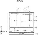
- FIG. 3 is a diagram illustrating an outline of a zinc battery according to a second embodiment.
- a zinc battery 1B illustrated in FIG. 3 has the same configuration as that of the zinc battery 1 illustrated in FIG. 1 , except that the zinc battery 1B further includes a stirrer 11, a heater 12, and a filter member 13.
- the stirrer 11 is a device for forcibly making the electrolytic solution 6 flow.
- concentration distribution of [Zn(OH) 4 ] 2- in the electrolytic solution 6 is made uniform quickly. Further, when the concentration of [Zn(OH) 4 ] 2- in the electrolytic solution 6 is not saturated, dissolution of the powder 7 in the electrolytic solution 6 is promoted.
- the stirrer 11 By the stirrer 11 being operated, the concentration of [Zn(OH) 4 ] 2- in the electrolytic solution 6 is increased quickly, the concentration having been decreased in the vicinity of the negative electrode 2 in association with battery charging; and the growth of dendrite is thus reduced further.
- the stirrer 11 is particularly useful, for example, when the shape of the case 8 is complicated, or upon battery charging in a low temperature region where natural convection of the electrolytic solution 6 or dissolution of the powder 7 in the electrolytic solution 6 is slow.
- the stirrer 11 may be operated at all times, but in terms of reduction in power consumption, the stirrer 11 is preferably operated only at the time of battery charging. Further, rotational speed of the stirrer 11 may be changed according to the consumption rate of [Zn(OH) 4 ] 2- in the electrolytic solution 6.
- the heater 12 is a device for heating the electrolytic solution 6.
- concentration of [Zn(OH) 4 ] 2- that is able to be dissolved in the electrolytic solution 6, that is, the saturation concentration is increased.
- concentration of [Zn(OH) 4 ] 2- dissolved in the electrolytic solution 6 is increased, and the growth of dendrite is reduced further.
- the filter member 13 is a member for filtering the powder 7 that is mixed in the electrolytic solution 6.
- the filter member 13 is arranged between: the powder 7 in the electrolytic solution 6; and the negative electrode 2 and positive electrode 3.
- the filter member 13 is formed so as to pass [Zn(OH) 4 ] 2- dissolved in the electrolytic solution 6 therethrough and to not pass the powder 7 also mixed in the electrolytic solution 6 therethrough. Thereby, occurrence of failure where, for example, the powder 7 reaches the porous body 4 and/or the coating 5 and causes clogging, or short-circuiting of the negative electrode 2 and the positive electrode 3 is caused is able to be reduced further.
- the powder 7 is able to exist movably in the electrolytic solution 6 in a range partitioned by the filter member 13 in the case 8. Further, when the powder 7 exists movably in the electrolytic solution 6, as the powder 7 moves, dissolution of zinc from the powder 7 that has gone in the electrolytic solution 6 low in concentration of [Zn(OH) 4 ] 2- is facilitated, and thus the concentration of [Zn(OH) 4 ] 2- in the electrolytic solution 6 is able to be maintained high.
- stirrer 11, the heater 12, and the filter member 13 are included, but not necessarily all of these are included, and they may be arranged selectively as necessary.
- the zinc battery 1B including the stirrer 11 is an example of a zinc flow battery.
- a zinc flow battery having a plurality of the negative electrodes 2 and a plurality of the positive electrode 3 alternately arranged therein will be described by use of FIG. 4A to FIG. 4C .
- FIG. 4A is a diagram illustrating an outline of a zinc flow battery according to the first embodiment
- FIG. 4B is a top view of the zinc flow battery illustrated in FIG. 4A .
- a zinc flow battery 100 illustrated in FIG. 4A and FIG. 4B includes, inside the zinc flow battery 100 formed of a case 23 and an upper plate 24: a reaction chamber 20 where charging and discharging reactions take place; and a stirring chamber 21 where the stirrer 11 is accommodated.
- FIG. 4A illustration of parts corresponding to the heater 12 and the filter member 13 illustrated in FIG. 3 has been omitted.
- illustration and description of the heater 12 and filter member 13 will be omitted, but these may be present or absent.
- the reaction chamber 20 and the stirring chamber 21 are adjacent to each other via a partition plate 22. Further, the case 8 is open at the top and bottom of the partition plate 22, and the reaction chamber 20 and the stirring chamber 21 are thus communicated with each other at the top and bottom of the partition plate 22.
- the electrolytic solution 6 filled into the case 8 forms a circulation flow path where the electrolytic solution 6 flows into the reaction chamber 20 from a lower part of the stirring chamber 21 and returns to the stirring chamber 21 from an upper part of the reaction chamber 20.
- the zinc flow battery 100 having such a configuration enables the electrolytic solution 6 to flow without use of a pump and a piping, and thus enables prevention of leakage of the electrolytic solution 6 from joints to the pump and piping.
- the reaction chamber 20 has the pluralities of electrodes alternately arranged along an X-axis direction, from a side closer to the stirring chamber 21, in the order of a negative electrode 2D, a positive electrode 3D, a negative electrode 2E, a positive electrode 3E, and a negative electrode 2F. These electrodes are held by a rack 25 enabling the replacement work therefor to be facilitated. Further, the powder 7 is arranged to be mixed in the electrolytic solution 6 at a lower part of the reaction chamber 20 separated from the stirrer 11, so that the powder 7 dispersed in association with the operation of the stirrer 11 does not reach the electrodes.
- FIG. 4C is a diagram for explanation of an example of the connection between the electrodes of the zinc flow battery 100 according to the first embodiment.
- the negative electrode 2D, negative electrode 2E, and negative electrode 2F are parallelly connected.
- the positive electrode 3D and positive electrode 3E are parallelly connected.
- the zinc flow battery 100 is configured to include a total of five electrodes with the negative electrodes and the positive electrodes being arranged alternately, but without being limited thereto, the zinc flow battery 100 may be configured to include five or more electrodes arranged alternately. Further, according to the above described embodiment, the zinc flow battery 100 is configured such that both of its end electrodes are negative electrodes (2D and 2F), but without being limited thereto, the zinc flow battery 100 may be configured such that both of its end electrodes are positive electrodes.
- the same numbers of negative electrodes and positive electrodes may be alternately arranged such that one of the end electrodes is a positive electrode and the other end electrode is a positive electrode. In that case, the electrodes may be connected in parallel or in series.
- the electrodes are arranged such that principal planes of the electrodes face the stirring chamber 21, but the embodiment is not limited to this arrangement.
- this point will be described by use of FIG. 5A and FIG. 5B .
- FIG. 5A is a diagram illustrating an outline of a zinc flow battery according to the second embodiment
- FIG. 5B is a side view of the zinc flow battery illustrated in FIG. 5A as viewed from a negative side along a Y-axis.
- a zinc flow battery 100A illustrated in FIG. 5A and FIG. 5B has the same configuration as that of the zinc flow battery 100 according to the first embodiment, except that the zinc flow battery 100A includes: electrodes arranged in the reaction chamber 20; and a rack 35 that makes the direction, in which the electrodes are supported, different, instead of the rack 25 that supports the electrodes.
- a side surface of each electrode is arranged to face the stirring chamber 21, and more specifically, a negative electrode 2H, a positive electrode 3H, a negative electrode 2I, a positive electrode 3I, and a negative electrode 2J are arranged side by side along a Y-axis direction.
- a structure that hinders circulation of the electrolytic solution 6 is not present between the stirring chamber 21 and each electrode, and distances between the stirring chamber 21 and the electrodes are substantially the same. Therefore, the zinc flow battery 100A according to the second embodiment enables more reduction of pressure loss associated with the circulation of the electrolytic solution 6 than in the zinc flow battery 100 according to the first embodiment, and thus enables smoother circulation of the electrolytic solution 6.
- FIG. 6 is a diagram illustrating an outline of a zinc flow battery according to a third embodiment.
- a zinc flow battery 100B illustrated in FIG. 6 includes a reaction unit 20A, a tank 30, pipings 26 and 27 connecting the reaction unit 20A and the tank 30 to each other, and an electrolytic solution supplying unit 31.
- the reaction unit 20A corresponds to the reaction chamber 20 in the zinc flow battery 100 according to the first embodiment.
- the electrolytic solution supplying unit 31 is, for example, a pump that is able to transfer the electrolytic solution 6.
- the electrolytic solution 6 is fed to the reaction unit 20A via the piping 27 by the electrolytic solution supplying unit 31 from the tank 30 provided separately from the case 23.
- [Zn(OH) 4 ] 2- in the electrolytic solution 6 that has flown into the reaction unit 20A is consumed at the negative electrodes 2D, 2E, and 2F, and is returned to the tank 30 in the state where the amount of [Zn(OH) 4 ] 2- dissolved in the electrolytic solution 6 has been decreased.
- the powder 7 is mixed in the electrolytic solution 6 in the tank 30, but without being limited thereto, the powder 7 may be mixed in the electrolytic solution 6 inside the reaction unit 20A, or mixed in the electrolytic solution 6 in both the reaction unit 20A and tank 30.
- the powder 7 is able to move in the electrolytic solution 6 inside the tank 30, or in the electrolytic solution 6 inside the tank 30 and reaction unit 20A. As the powder 7 moves in the electrolytic solution 6, dissolution of zinc from the powder 7 is promoted when the powder 7 goes in the electrolytic solution 6 low in concentration of [Zn(OH) 4 ] 2- , and thus it becomes easier for the concentration of [Zn(OH) 4 ] 2- in the electrolytic solution 6 to be maintained high.
- the present invention is not limited to these embodiments, and various modifications may be made without departing from the gist of the invention.
- the zinc flow batteries 100 to 100B according to the embodiments have been described, without being limited thereto, the zinc batteries 1 to 1B according to the embodiments and modified example may be used in the reaction chamber 20 of the zinc flow battery 100 or 100A, or in the reaction unit 20A of the zinc flow battery 100B.
- the negative electrode 2 does not include a negative electrode active material, such as a zinc species, but without being limited thereto, the negative electrode 2 may include a negative electrode active material. Note that, in terms of reduction of time degradation, such as shape change, the amount of negative electrode active material included in the negative electrode 2 is preferably little.
- the porous body 4 covers the negative electrode 2, but without being limited thereto, the porous body 4 is just preferably arranged between the negative electrode 2 and the coating 5. Further, the porous body 4 may be in contact with the coating 5, or arranged separately from the coating 5. Furthermore, the porous body 4 may be arranged separately from the negative electrode 2.
- the zinc flow battery 100 according to the first embodiment may have a layered structure where the porous body 4 is each arranged between the negative electrode 2D and positive electrode 3D, between the positive electrode 3D and negative electrode 2E, between the negative electrode 2E and positive electrode 3E, and between the positive electrode 3E and negative electrode 2F. Moreover, the porous body 4 may be not arranged at all.
- the coating 5 covers the positive electrode 3, but without being limited thereto, the coating 5 is just preferably arranged between the negative electrode 2 (or the porous body 4) and the positive electrode 3.
Landscapes
- Chemical & Material Sciences (AREA)
- Chemical Kinetics & Catalysis (AREA)
- Electrochemistry (AREA)
- General Chemical & Material Sciences (AREA)
- Engineering & Computer Science (AREA)
- Manufacturing & Machinery (AREA)
- Life Sciences & Earth Sciences (AREA)
- Sustainable Development (AREA)
- Sustainable Energy (AREA)
- Battery Electrode And Active Subsutance (AREA)
- Secondary Cells (AREA)
- Hybrid Cells (AREA)
- Filling, Topping-Up Batteries (AREA)
Abstract
Description
- Embodiments disclosed herein relate to a zinc battery and a zinc flow battery.
- A flow battery having an electrolytic solution, which contains tetrahydroxy zincate ions ([Zn(OH)4]2-) and is circulated between a positive electrode and a negative electrode, has been known conventionally (as seen in, for example, Non-Patent Literature 1).
- Further, a technique for reducing growth of dendrite by covering a negative electrode including an active material, such as a zinc species, with an ion conductive layer having selective ion conductivity has been proposed (as seen in, for example, Patent Literature 1).
- Patent Literature 1: Japanese Patent Application Laid-open No.
2015-185259 - Non-Patent Literature 1: Y. Ito., et al.: Zinc Morphology in Zinc-Nickel Flow Assisted Batteries and Impact on Performance, Journal of Power Sources, Vol. 196, pp. 2340-2345, 2011
- A zinc battery according to an aspect of embodiments includes a negative electrode and a positive electrode, an electrolytic solution, and a powder. The electrolytic solution contacts with the negative electrode and the positive electrode. The powder includes zinc and mixed in the electrolytic solution.
-
-
FIG. 1 is a diagram illustrating an outline of a zinc battery according to a first embodiment. -
FIG. 2 is a diagram illustrating an outline of a zinc battery according to a modified example of the first embodiment. -
FIG. 3 is a diagram illustrating an outline of a zinc battery according to a second embodiment. -
FIG. 4A is a diagram illustrating an outline of a zinc flow battery according to the first embodiment. -
FIG. 4B is a diagram illustrating an outline of the zinc flow battery according to the first embodiment. -
FIG. 4C is a diagram for explanation of an example of connection between electrodes of the zinc flow battery according to the first embodiment. -
FIG. 5A is a diagram illustrating an outline of a zinc flow battery according to the second embodiment. -
FIG. 5B is a diagram illustrating an outline of the zinc flow battery according to the second embodiment. -
FIG. 6 is a diagram illustrating an outline of a zinc flow battery according to a third embodiment. - Hereinafter, by reference to the appended drawings, embodiments of a zinc battery and a zinc flow battery disclosed by this application will be described in detail. The invention is not limited by the embodiments described below.
-
FIG. 1 is a diagram illustrating an outline of a zinc battery according to a first embodiment. Azinc battery 1 illustrated inFIG. 1 includes anegative electrode 2, apositive electrode 3, a porous body 4, a coating 5, anelectrolytic solution 6, apowder 7, acase 8, and anupper plate 9. - For ease of understanding of the description,
FIG. 1 illustrates a three-dimensional rectangular coordinate system including a Z-axis having a positive direction vertically upward and a negative direction vertically downward. This rectangular coordinate system may be illustrated in any other drawing used in the description later. - The
negative electrode 2 includes a negative electrode active material as metal. For example, a metal plate made of stainless steel, copper, or the like, or a stainless steel or copper plate having a surface that has been plated with nickel, tin, or zinc, may be used as thenegative electrode 2. Further, a metal plate having a plated surface that has been partially oxidized may be used as thenegative electrode 2. - The
positive electrode 3 is an electrically conductive member containing, for example, a nickel compound, a manganese compound, or a cobalt compound, which serves as a positive electrode active material. The nickel compound is preferably, for example, nickel oxyhydroxide, nickel hydroxide, or cobalt-containing nickel hydroxide. The manganese compound is preferably, for example, manganese dioxide. The cobalt compound is preferably, for example, cobalt hydroxide or cobalt oxyhydroxide. Further, thepositive electrode 3 may include graphite, carbon black, an electrically conductive resin, or the like. In terms of oxidation-reduction potential for decomposition of theelectrolytic solution 6, thepositive electrode 3 preferably contains the nickel compound. - The
electrolytic solution 6 is an alkali aqueous solution containing a zinc species. The zinc species in theelectrolytic solution 6 is dissolved in the electrolytic solution as [Zn(OH)4]2-. For example, an alkali aqueous solution containing K+ and OH- and saturated with the zinc species may be used as theelectrolytic solution 6. Theelectrolytic solution 6 is preferably prepared, together with thepowder 7, which will be described later. For example, a 6.7 moldm-3 aqueous potassium hydroxide solution may be used as the alkali aqueous solution. Further, theelectrolytic solution 6 may be prepared by addition of ZnO into the aqueous potassium hydroxide solution at a ratio of 0.5 mol to 1 dm-3, and as necessary, addition of thepowder 7 described later. - The
powder 7 includes zinc. Specifically, thepowder 7 is, for example, zinc oxide or zinc hydroxide, which has been processed into or formed as powder. Thepowder 7 easily dissolves in an alkali aqueous solution, but settles out without dissolving in theelectrolytic solution 6 saturated with the zinc species, and some of thepowder 7 is also mixed in theelectrolytic solution 6 in a dispersed or floating state. If theelectrolytic solution 6 has been left to stand for a long period of time, most of thepowder 7 may have settled out, but if convection or the like is caused in theelectrolytic solution 6, some of thepowder 7 that has settled out will be in a state dispersed or floating in theelectrolytic solution 6. In other words, thepowder 7 exists movably in theelectrolytic solution 6. Being movable herein does not mean that a part of thepowder 7 is able to move only in a local space formed in another part of thepowder 7 surrounding that part of thepowder 7, but means that by moving in theelectrolytic solution 6 from an initial position to a different position, thepowder 7 is exposed to theelectrolytic solution 6 that is not at the initial position. Further, the meaning of being movable includes that thepowder 7 is able to move to the vicinity of both thenegative electrode 2 andpositive electrode 3, and that thepowder 7 is able to move to almost anywhere in theelectrolytic solution 6 that is in thecase 8. When [Zn(OH)4]2-, which is the zinc species dissolved in theelectrolytic solution 6, is consumed, thepowder 7 that is also mixed in theelectrolytic solution 6 is dissolved until the zinc species dissolved in theelectrolytic solution 6 is saturated, such that thepowder 7 and theelectrolytic solution 6 maintain their equilibrium state. - Electrode reactions in a nickel-zinc battery, which is an example of the
zinc battery 1, will be described, the nickel-zinc battery having nickel hydroxide used therein as a positive electrode active material. Reaction formulae for thepositive electrode 3 and thenegative electrode 2 upon battery charging are respectively as follows. -
- Positive electrode: Ni(OH)2 + OH- → NiOOH + H2O + e-
- Negative electrode: [Zn(OH)4]2- + 2e- → Zn + 4OH-
- There is generally concern that dendrite that has been generated at the
negative electrode 2 in association with these reactions will grow toward thepositive electrode 3, and thenegative electrode 2 and thepositive electrode 3 will become electrically conductive to each other. As evident from the reaction formulae, at thenegative electrode 2, in association with deposition of zinc by the battery charging, concentration of [Zn(OH)4]2- in the vicinity of thenegative electrode 2 is decreased. It has been found that this phenomenon of the concentration of [Zn(OH)4]2- being decreased in the vicinity of the deposited zinc is one cause of the growth of dendrite. In other words, by resupply of [Zn(OH)4]2- in theelectrolytic solution 6 consumed upon the battery charging, concentration of [Zn(OH)4]2- that is the zinc species in theelectrolytic solution 6 is maintained in the saturated state. Thereby, the growth of dendrite is reduced, and the electric conduction between thenegative electrode 2 and thepositive electrode 3 is thus reduced. - Accordingly, the
zinc battery 1 according to the first embodiment has thepowder 7 including zinc, mixed also in theelectrolytic solution 6. Thereby, when [Zn(OH)4]2- in theelectrolytic solution 6 is consumed by battery charging, [Zn(OH)4]2- is resupplied in theelectrolytic solution 6 by dissolution of zinc in thepowder 7 in accordance with the consumption. Therefore, the concentration of [Zn(OH)4]2- in theelectrolytic solution 6 is able to be maintained in the saturated state, and electric conduction between thenegative electrode 2 and thepositive electrode 3 associated with the growth of dendrite is thus able to be reduced. - Examples of the
powder 7 include, in addition to zinc oxide and zinc hydroxide: metallic zinc; calcium zincate; zinc carbonate; zinc sulfate; and zinc chloride, where zinc oxide and zinc hydroxide are preferable. - Further, Zn is consumed and [Zn(OH)4]2- is generated by electric discharge at the
negative electrode 2, but since theelectrolytic solution 6 is already in the saturated state, ZnO is deposited in theelectrolytic solution 6 from [Zn(OH)4]2- that has become excessive. Zinc consumed at thenegative electrode 2 upon the electric discharge is zinc that has been deposited on the surface of thenegative electrode 2 upon battery charging. Therefore, differently from a case where charging and discharging are basically repeated by use of a negative electrode containing a zinc species, so-called shape change where the surface shape of thenegative electrode 2 changes is not caused. Thereby, thezinc battery 1 according to the first embodiment enables reduction of time degradation of thenegative electrode 2. Depending on the state of theelectrolytic solution 6; Zn(OH)2, or a mixture of ZnO and Zn(OH)2 may be deposited from [Zn(OH)4]2- that has become excessive. - By reference back to
FIG. 1 , thezinc battery 1 according to the first embodiment will be described further. The porous body 4 covers thenegative electrode 2. The porous body 4 is formed of a material having electric conductivity, for example, carbon felt. When the porous body 4 is used, the reaction field between theelectrolytic solution 6 and thenegative electrode 2 is enlarged, the reaction rate upon charging and discharging is improved, and the generation of dendrite associated with centralization of the reaction field is reduced. Further, theelectrolytic solution 6 is diffused over the whole surface of thenegative electrode 2 via voids in the porous body 4, and use efficiency of thenegative electrode 2 is thus improved. Furthermore, when the porous body 4 and thenegative electrode 2 are in contact with each other, for example, electric resistance at thenegative electrode 2 is decreased by increase in substantial specific surface area of thenegative electrode 2, and the power collection performance is thus improved. Accordingly, by thenegative electrode 2 being covered with the porous body 4 having electric conductivity, the battery performance is improved. - The coating 5 covers the
positive electrode 3. The coating 5 has hydroxide ion conductivity, and conducts hydroxide ions related to the electrode reactions. Further, the coating 5 is preferably formed densely such that the zinc metal and thepowder 7 do not pass through the coating 5. Thereby, failure where thenegative electrode 2 and thepositive electrode 3 become electrically conductive to each other is able to be reduced further, the failure being caused by penetration of the grown dendrite through the coating 5 or passage of thepowder 7 through the coating 5. Being dense herein means having a relative density of 90% or more, preferably 92% or more, and more preferably 95% or more, as calculated by the Archimedes method. Thickness of the coating 5 is preferably 10 µm to 1000 µm, and more preferably 100 µm to 500 µm. However, the relative density and thickness of the coating 5 are not limited to those mentioned above, as long as the penetration of dendrite and the passage of thepowder 7 through the coating 5 are able to be reduced. - Preferably, the coating 5 selectively allows hydroxide ions to permeate therethrough, but reduces permeation of metal ions, such as [Zn(OH)4]2-, having an ionic radius larger than that of hydroxide ions. By this reduction of permeation of metal ions, such as [Zn(OH)4]2-, by the coating 5; generation of dendrite inside the coating 5 and in the vicinity of the
positive electrode 3 is reduced, and thus electric conduction between thenegative electrode 2 and thepositive electrode 3 is able to be reduced further. - The coating 5 is preferably formed by use of, for example, a gelatinous anion conductive material having a three-dimensional structure like organic hydrogel, or a solid polymer type anion conductive material. The solid polymer type anion conductive material includes, for example, a polymer, and one or more compounds selected from the group consisting of: an oxide, a hydroxide, a layered double hydroxide, a sulfate compound, and a phosphate compound, each of which contains one or more elements selected from the 1st group to the 17th group of the periodic table.
- The
case 8 and theupper plate 9 are formed of, for example, a resin material having alkali resistance and insulation properties, such as polystyrene, polypropylene, polyethylene terephthalate, or polytetrafluoroethylene.
Thecase 8 and theupper plate 9 are preferably formed of the same material, but may be formed of materials different from each other. - Further, the
zinc battery 1 having the singlenegative electrode 2 correspondingly to the singlepositive electrode 3 has been described above with respect to the embodiment, but the embodiment is not limited to thiszinc battery 1. This point will be described by use ofFIG. 2 . -
FIG. 2 is a diagram illustrating an outline of a zinc battery according to a modified example of the first embodiment. Azinc battery 1A illustrated inFIG. 2 has the same configuration as that of thezinc battery 1 illustrated inFIG. 1 , except that thezinc battery 1A includes, instead of thepositive electrode 3 and the negative electrode 2:negative electrodes positive electrode 3A. InFIG. 2 , illustration of parts corresponding to the porous body 4 and coating 5 illustrated inFIG. 1 has been omitted. Hereinafter, unless otherwise noted, illustration and description of the porous body 4 and coating 5 will be omitted. - The
negative electrodes positive electrode 3A interposed between thenegative electrodes negative electrode 2A and thenegative electrode 2B are connected in parallel, and the current density per negative electrode is lower than that in thezinc battery 1 illustrated inFIG. 1 . Therefore, thezinc battery 1A according to the modified example of the first embodiment enables further reduction of generation of dendrite at thenegative electrodes negative electrodes positive electrode 3A is thus able to be reduced further. -
FIG. 3 is a diagram illustrating an outline of a zinc battery according to a second embodiment. Azinc battery 1B illustrated inFIG. 3 has the same configuration as that of thezinc battery 1 illustrated inFIG. 1 , except that thezinc battery 1B further includes astirrer 11, aheater 12, and afilter member 13. - The
stirrer 11 is a device for forcibly making theelectrolytic solution 6 flow. By theelectrolytic solution 6 being made to flow, concentration distribution of [Zn(OH)4]2- in theelectrolytic solution 6 is made uniform quickly. Further, when the concentration of [Zn(OH)4]2- in theelectrolytic solution 6 is not saturated, dissolution of thepowder 7 in theelectrolytic solution 6 is promoted. By thestirrer 11 being operated, the concentration of [Zn(OH)4]2- in theelectrolytic solution 6 is increased quickly, the concentration having been decreased in the vicinity of thenegative electrode 2 in association with battery charging; and the growth of dendrite is thus reduced further. Thestirrer 11 is particularly useful, for example, when the shape of thecase 8 is complicated, or upon battery charging in a low temperature region where natural convection of theelectrolytic solution 6 or dissolution of thepowder 7 in theelectrolytic solution 6 is slow. - The
stirrer 11 may be operated at all times, but in terms of reduction in power consumption, thestirrer 11 is preferably operated only at the time of battery charging. Further, rotational speed of thestirrer 11 may be changed according to the consumption rate of [Zn(OH)4]2- in theelectrolytic solution 6. - The
heater 12 is a device for heating theelectrolytic solution 6. By heating of theelectrolytic solution 6, the concentration of [Zn(OH)4]2- that is able to be dissolved in theelectrolytic solution 6, that is, the saturation concentration, is increased. Thereby, the concentration of [Zn(OH)4]2- dissolved in theelectrolytic solution 6 is increased, and the growth of dendrite is reduced further. - The
filter member 13 is a member for filtering thepowder 7 that is mixed in theelectrolytic solution 6. Thefilter member 13 is arranged between: thepowder 7 in theelectrolytic solution 6; and thenegative electrode 2 andpositive electrode 3. Thefilter member 13 is formed so as to pass [Zn(OH)4]2- dissolved in theelectrolytic solution 6 therethrough and to not pass thepowder 7 also mixed in theelectrolytic solution 6 therethrough. Thereby, occurrence of failure where, for example, thepowder 7 reaches the porous body 4 and/or the coating 5 and causes clogging, or short-circuiting of thenegative electrode 2 and thepositive electrode 3 is caused is able to be reduced further. - The
powder 7 is able to exist movably in theelectrolytic solution 6 in a range partitioned by thefilter member 13 in thecase 8. Further, when thepowder 7 exists movably in theelectrolytic solution 6, as thepowder 7 moves, dissolution of zinc from thepowder 7 that has gone in theelectrolytic solution 6 low in concentration of [Zn(OH)4]2- is facilitated, and thus the concentration of [Zn(OH)4]2- in theelectrolytic solution 6 is able to be maintained high. - According to the above description of the embodiment, all of the
stirrer 11, theheater 12, and thefilter member 13 are included, but not necessarily all of these are included, and they may be arranged selectively as necessary. - The
zinc battery 1B including thestirrer 11 is an example of a zinc flow battery. Hereinafter, a zinc flow battery having a plurality of thenegative electrodes 2 and a plurality of thepositive electrode 3 alternately arranged therein will be described by use ofFIG. 4A to FIG. 4C . -
FIG. 4A is a diagram illustrating an outline of a zinc flow battery according to the first embodiment, andFIG. 4B is a top view of the zinc flow battery illustrated inFIG. 4A . - A
zinc flow battery 100 illustrated inFIG. 4A andFIG. 4B includes, inside thezinc flow battery 100 formed of acase 23 and an upper plate 24: areaction chamber 20 where charging and discharging reactions take place; and a stirringchamber 21 where thestirrer 11 is accommodated. InFIG. 4A , illustration of parts corresponding to theheater 12 and thefilter member 13 illustrated inFIG. 3 has been omitted. Hereinafter, illustration and description of theheater 12 andfilter member 13 will be omitted, but these may be present or absent. - The
reaction chamber 20 and the stirringchamber 21 are adjacent to each other via apartition plate 22. Further, thecase 8 is open at the top and bottom of thepartition plate 22, and thereaction chamber 20 and the stirringchamber 21 are thus communicated with each other at the top and bottom of thepartition plate 22. By operation of thestirrer 11, theelectrolytic solution 6 filled into thecase 8 forms a circulation flow path where theelectrolytic solution 6 flows into thereaction chamber 20 from a lower part of the stirringchamber 21 and returns to the stirringchamber 21 from an upper part of thereaction chamber 20. Thezinc flow battery 100 having such a configuration enables theelectrolytic solution 6 to flow without use of a pump and a piping, and thus enables prevention of leakage of theelectrolytic solution 6 from joints to the pump and piping. - Further, the
reaction chamber 20 has the pluralities of electrodes alternately arranged along an X-axis direction, from a side closer to the stirringchamber 21, in the order of anegative electrode 2D, apositive electrode 3D, anegative electrode 2E, apositive electrode 3E, and anegative electrode 2F. These electrodes are held by arack 25 enabling the replacement work therefor to be facilitated. Further, thepowder 7 is arranged to be mixed in theelectrolytic solution 6 at a lower part of thereaction chamber 20 separated from thestirrer 11, so that thepowder 7 dispersed in association with the operation of thestirrer 11 does not reach the electrodes. - When the
zinc flow battery 100 is charged, [Zn(OH)4]2- dissolved in theelectrolytic solution 6 in the vicinity of thenegative electrodes electrolytic solution 6 is decreased. When the amount of [Zn(OH)4]2- dissolved in theelectrolytic solution 6 is decreased, zinc is dissolved from thepowder 7 in accordance with the decrease, and [Zn(OH)4]2- is resupplied in theelectrolytic solution 6. By supply of theelectrolytic solution 6 having the amount of dissolved [Zn(OH)4]2- adjusted therein to the vicinity of thenegative electrodes negative electrodes negative electrode 2D andpositive electrode 3D; thenegative electrode 2E andpositive electrode 3D; thenegative electrode 2E andpositive electrode 3E; and thenegative electrode 2F andpositive electrode 3E, is able to be reduced. - Next, connection between the electrodes in the
zinc flow battery 100 will be described.FIG. 4C is a diagram for explanation of an example of the connection between the electrodes of thezinc flow battery 100 according to the first embodiment. - As illustrated in
FIG. 4C , thenegative electrode 2D,negative electrode 2E, andnegative electrode 2F are parallelly connected. Further, thepositive electrode 3D andpositive electrode 3E are parallelly connected. By such parallel connection between the negative electrodes and between the positive electrodes, the electrodes of thezinc flow battery 100 are able to be connected appropriately and used, where the total number of the negative electrodes and the total number of the positive electrodes are different from each other. - According to the above described embodiment, the
zinc flow battery 100 is configured to include a total of five electrodes with the negative electrodes and the positive electrodes being arranged alternately, but without being limited thereto, thezinc flow battery 100 may be configured to include five or more electrodes arranged alternately. Further, according to the above described embodiment, thezinc flow battery 100 is configured such that both of its end electrodes are negative electrodes (2D and 2F), but without being limited thereto, thezinc flow battery 100 may be configured such that both of its end electrodes are positive electrodes. - Further, the same numbers of negative electrodes and positive electrodes may be alternately arranged such that one of the end electrodes is a positive electrode and the other end electrode is a positive electrode. In that case, the electrodes may be connected in parallel or in series.
- According to the above described embodiment, the electrodes are arranged such that principal planes of the electrodes face the stirring
chamber 21, but the embodiment is not limited to this arrangement. Hereinafter, this point will be described by use ofFIG. 5A andFIG. 5B . -
FIG. 5A is a diagram illustrating an outline of a zinc flow battery according to the second embodiment, andFIG. 5B is a side view of the zinc flow battery illustrated inFIG. 5A as viewed from a negative side along a Y-axis. - A
zinc flow battery 100A illustrated inFIG. 5A andFIG. 5B has the same configuration as that of thezinc flow battery 100 according to the first embodiment, except that thezinc flow battery 100A includes: electrodes arranged in thereaction chamber 20; and arack 35 that makes the direction, in which the electrodes are supported, different, instead of therack 25 that supports the electrodes. - In the
zinc flow battery 100A, a side surface of each electrode is arranged to face the stirringchamber 21, and more specifically, anegative electrode 2H, apositive electrode 3H, a negative electrode 2I, a positive electrode 3I, and anegative electrode 2J are arranged side by side along a Y-axis direction. A structure that hinders circulation of theelectrolytic solution 6 is not present between the stirringchamber 21 and each electrode, and distances between the stirringchamber 21 and the electrodes are substantially the same. Therefore, thezinc flow battery 100A according to the second embodiment enables more reduction of pressure loss associated with the circulation of theelectrolytic solution 6 than in thezinc flow battery 100 according to the first embodiment, and thus enables smoother circulation of theelectrolytic solution 6. -
FIG. 6 is a diagram illustrating an outline of a zinc flow battery according to a third embodiment. Azinc flow battery 100B illustrated inFIG. 6 includes areaction unit 20A, atank 30,pipings reaction unit 20A and thetank 30 to each other, and an electrolyticsolution supplying unit 31. Thereaction unit 20A corresponds to thereaction chamber 20 in thezinc flow battery 100 according to the first embodiment. The electrolyticsolution supplying unit 31 is, for example, a pump that is able to transfer theelectrolytic solution 6. - The
electrolytic solution 6 is fed to thereaction unit 20A via the piping 27 by the electrolyticsolution supplying unit 31 from thetank 30 provided separately from thecase 23. Upon battery charging, [Zn(OH)4]2- in theelectrolytic solution 6 that has flown into thereaction unit 20A is consumed at thenegative electrodes tank 30 in the state where the amount of [Zn(OH)4]2- dissolved in theelectrolytic solution 6 has been decreased. When theelectrolytic solution 6 with the decreased amount of [Zn(OH)4]2- dissolved in theelectrolytic solution 6 is returned to thetank 30, zinc is dissolved from thepowder 7 also mixed in thetank 30 in accordance with the return, and [Zn(OH)4]2- is resupplied in theelectrolytic solution 6. By supply of theelectrolytic solution 6 having the amount of [Zn(OH)4]2- dissolved therein adjusted, to the vicinity of thenegative electrodes negative electrodes negative electrode 2D andpositive electrode 3D, thenegative electrode 2E andpositive electrode 3D, thenegative electrode 2E andpositive electrode 3E, and thenegative electrode 2F andpositive electrode 3E, is able to be reduced. - According to the above description of the embodiment, the
powder 7 is mixed in theelectrolytic solution 6 in thetank 30, but without being limited thereto, thepowder 7 may be mixed in theelectrolytic solution 6 inside thereaction unit 20A, or mixed in theelectrolytic solution 6 in both thereaction unit 20A andtank 30. - The
powder 7 is able to move in theelectrolytic solution 6 inside thetank 30, or in theelectrolytic solution 6 inside thetank 30 andreaction unit 20A. As thepowder 7 moves in theelectrolytic solution 6, dissolution of zinc from thepowder 7 is promoted when thepowder 7 goes in theelectrolytic solution 6 low in concentration of [Zn(OH)4]2-, and thus it becomes easier for the concentration of [Zn(OH)4]2- in theelectrolytic solution 6 to be maintained high. - Hereinbefore, embodiments of the present invention have been described, but the present invention is not limited to these embodiments, and various modifications may be made without departing from the gist of the invention. For example, although the
zinc flow batteries 100 to 100B according to the embodiments have been described, without being limited thereto, thezinc batteries 1 to 1B according to the embodiments and modified example may be used in thereaction chamber 20 of thezinc flow battery reaction unit 20A of thezinc flow battery 100B. - Further, according to the above description of the embodiment, the
negative electrode 2 does not include a negative electrode active material, such as a zinc species, but without being limited thereto, thenegative electrode 2 may include a negative electrode active material. Note that, in terms of reduction of time degradation, such as shape change, the amount of negative electrode active material included in thenegative electrode 2 is preferably little. - According to the above description of the embodiment, the porous body 4 covers the
negative electrode 2, but without being limited thereto, the porous body 4 is just preferably arranged between thenegative electrode 2 and the coating 5. Further, the porous body 4 may be in contact with the coating 5, or arranged separately from the coating 5. Furthermore, the porous body 4 may be arranged separately from thenegative electrode 2. For example, thezinc flow battery 100 according to the first embodiment may have a layered structure where the porous body 4 is each arranged between thenegative electrode 2D andpositive electrode 3D, between thepositive electrode 3D andnegative electrode 2E, between thenegative electrode 2E andpositive electrode 3E, and between thepositive electrode 3E andnegative electrode 2F. Moreover, the porous body 4 may be not arranged at all. - According to the above description of the embodiment, the coating 5 covers the
positive electrode 3, but without being limited thereto, the coating 5 is just preferably arranged between the negative electrode 2 (or the porous body 4) and thepositive electrode 3. - Additional advantages and modifications will readily occur to those skilled in the art. Therefore, the invention in its broader aspects is not limited to the specific details and representative embodiments shown and described herein. Accordingly, various modifications may be made without departing from the spirit or scope of the general inventive concept as defined by the appended claims and their equivalents.
-
- 1, 1A, 1B ZINC BATTERY
- 2, 2A, 2B,
2D TO 2H TO 2J NEGATIVE ELECTRODE - 3, 3A, 3D, 3E, 3H, 3I POSITIVE ELECTRODE
- 4 POROUS BODY
- 5 COATING
- 6 ELECTROLYTIC SOLUTION
- 7 POWDER
- 11 STIRRER
- 12 HEATER
- 13 FILTER MEMBER
- 20 REACTION CHAMBER
- 20A REACTION UNIT
- 26, 27 PIPING
- 30 TANK
- 31 ELECTROLYTIC SOLUTION SUPPLYING UNIT
- 100, 100A, 100B ZINC FLOW BATTERY
Claims (10)
- A zinc battery, comprising:a negative electrode and a positive electrode;an electrolytic solution in contact with the negative electrode and the positive electrode; anda powder including zinc and mixed in the electrolytic solution.
- The zinc battery according to claim 1, wherein the powder can move in the electrolytic solution.
- The zinc battery according to claim 1 or 2, wherein
the negative electrode consumes, upon battery charging, a zinc species dissolved in the electrolytic solution, and
the zinc species that has been consumed is resupplied, by dissolution of the zinc included in the powder into the electrolytic solution. - The zinc battery according to any one of claims 1 to 3, wherein the positive electrode has been covered by a coating having hydroxide ion conductivity.
- The zinc battery according to claim 4, further comprising a porous body having electric conductivity between the negative electrode and the coating.
- The zinc battery according to any one of claims 1 to 5, further comprising a heater that heats the electrolytic solution.
- The zinc battery according to any one of claims 1 to 6, wherein the negative electrode includes a first electrode and a second electrode that are arranged to face each other with the positive electrode interposed between the first and second electrodes.
- The zinc battery according to any one of claims 1 to 7, wherein the electrolytic solution is an alkali aqueous solution saturated with a zinc species.
- A zinc flow battery, comprising:a reaction chamber including the zinc battery according to any one of claims 1 to 8; anda stirrer that stirs the electrolytic solution.
- A zinc flow battery, comprising:a reaction unit including a negative electrode and a positive electrode;an electrolytic solution in contact with the negative electrode and the positive electrode;a tank storing therein the electrolytic solution;a powder mixed in the electrolytic solution, the powder including zinc;a piping that circulates the electrolytic solution between the reaction unit and the tank; andan electrolytic solution supplying unit that feeds the electrolytic solution from the tank to the reaction unit.
Applications Claiming Priority (2)
| Application Number | Priority Date | Filing Date | Title |
|---|---|---|---|
| JP2016109567 | 2016-05-31 | ||
| PCT/JP2017/020016 WO2017209100A1 (en) | 2016-05-31 | 2017-05-30 | Zinc cell and zinc flow cell |
Publications (2)
| Publication Number | Publication Date |
|---|---|
| EP3467932A1 true EP3467932A1 (en) | 2019-04-10 |
| EP3467932A4 EP3467932A4 (en) | 2020-02-26 |
Family
ID=60478583
Family Applications (1)
| Application Number | Title | Priority Date | Filing Date |
|---|---|---|---|
| EP17806654.4A Withdrawn EP3467932A4 (en) | 2016-05-31 | 2017-05-30 | ZINC CELL AND ZINC FLOW CELL |
Country Status (5)
| Country | Link |
|---|---|
| US (1) | US20200321661A1 (en) |
| EP (1) | EP3467932A4 (en) |
| JP (1) | JP6694955B2 (en) |
| CN (1) | CN109314285A (en) |
| WO (1) | WO2017209100A1 (en) |
Cited By (2)
| Publication number | Priority date | Publication date | Assignee | Title |
|---|---|---|---|---|
| US11228058B2 (en) | 2018-04-27 | 2022-01-18 | Kyocera Corporation | Flow battery, flow battery system, and control method |
| EP3961767A4 (en) * | 2019-04-26 | 2024-02-21 | Kyocera Corporation | SECONDARY BATTERY AND SECONDARY BATTERY SYSTEM |
Families Citing this family (14)
| Publication number | Priority date | Publication date | Assignee | Title |
|---|---|---|---|---|
| JP2019121491A (en) * | 2017-12-28 | 2019-07-22 | 京セラ株式会社 | Flow battery system and control method |
| WO2019151454A1 (en) * | 2018-01-31 | 2019-08-08 | 京セラ株式会社 | Flow battery |
| JP2019133860A (en) * | 2018-01-31 | 2019-08-08 | 京セラ株式会社 | Flow battery |
| JP2019133864A (en) * | 2018-01-31 | 2019-08-08 | 京セラ株式会社 | Flow battery |
| CN108232268B (en) * | 2018-02-28 | 2024-08-02 | 超威电源集团有限公司 | Zinc-nickel flow battery for stirring solution |
| JP7025243B2 (en) * | 2018-02-28 | 2022-02-24 | 京セラ株式会社 | Flow battery |
| CN108808053B (en) * | 2018-06-22 | 2021-10-15 | 浙江裕源储能科技有限公司 | Zinc-nickel liquid flow energy storage battery |
| JP2020038754A (en) * | 2018-08-31 | 2020-03-12 | 京セラ株式会社 | Flow battery |
| JP7109315B2 (en) * | 2018-08-31 | 2022-07-29 | 京セラ株式会社 | flow battery |
| JP7657554B2 (en) | 2019-09-18 | 2025-04-07 | マクセル株式会社 | Secondary battery |
| JP7167903B2 (en) * | 2019-11-11 | 2022-11-09 | トヨタ自動車株式会社 | zinc secondary battery |
| CN113782841B (en) * | 2021-06-30 | 2023-07-07 | 超威电源集团有限公司 | Zinc battery electrolyte and preparation method thereof |
| JP7687275B2 (en) * | 2022-05-19 | 2025-06-03 | トヨタ自動車株式会社 | Zinc secondary battery |
| EP4679572A1 (en) | 2023-03-09 | 2026-01-14 | Sojitz Institute of Innovative Technologies, Ltd. | Regeneration device for regenerating used fuel of fuel cell that uses metal as fuel, regeneration method, and fuel cell comprising regeneration device |
Family Cites Families (15)
| Publication number | Priority date | Publication date | Assignee | Title |
|---|---|---|---|---|
| JPS5040459B1 (en) * | 1970-04-07 | 1975-12-24 | ||
| JPS5644540B2 (en) * | 1973-12-28 | 1981-10-20 | ||
| JPS5115126A (en) * | 1974-07-27 | 1976-02-06 | Kogyo Gijutsuin | |
| JPS5629339B2 (en) * | 1974-11-21 | 1981-07-08 | ||
| FR2298195A1 (en) * | 1975-01-14 | 1976-08-13 | Comp Generale Electricite | AIR-ZINC ELECTROCHEMICAL GENERATOR |
| JPS5963672A (en) * | 1982-09-30 | 1984-04-11 | Japan Storage Battery Co Ltd | Nickel-zinc storage battery |
| DE3562307D1 (en) * | 1984-12-12 | 1988-05-26 | Matsushita Electric Industrial Co Ltd | Zinc-alkaline battery |
| US6171725B1 (en) * | 1996-11-26 | 2001-01-09 | Kao Corporation | Negative electrode material for non-aqueous secondary battery |
| US6630262B2 (en) * | 2001-03-09 | 2003-10-07 | De-Qian Yang | Metal-gas cell battery with soft pocket |
| JP3889605B2 (en) * | 2001-10-31 | 2007-03-07 | ニッポン高度紙工業株式会社 | High ion conductive solid electrolyte and electrochemical system using the solid electrolyte |
| JP2004342519A (en) * | 2003-05-16 | 2004-12-02 | M & G Eco Battery Institute Co Ltd | Battery using paste-type thin electrode and method of manufacturing the same |
| JP5740357B2 (en) * | 2012-06-29 | 2015-06-24 | 株式会社日立製作所 | Large capacity storage device |
| US20150311503A1 (en) * | 2012-11-09 | 2015-10-29 | Research Foundation Of The City University Of New York | Secondary Zinc-Manganese Dioxide Batteries for High Power Applications |
| JP6211800B2 (en) * | 2013-05-23 | 2017-10-11 | 旭化成株式会社 | Electrolyte flow type secondary battery |
| EP3076476B1 (en) * | 2014-07-09 | 2018-09-19 | NGK Insulators, Ltd. | Nickel-zinc battery |
-
2017
- 2017-05-30 US US16/305,317 patent/US20200321661A1/en not_active Abandoned
- 2017-05-30 CN CN201780033112.9A patent/CN109314285A/en active Pending
- 2017-05-30 JP JP2018520914A patent/JP6694955B2/en not_active Expired - Fee Related
- 2017-05-30 WO PCT/JP2017/020016 patent/WO2017209100A1/en not_active Ceased
- 2017-05-30 EP EP17806654.4A patent/EP3467932A4/en not_active Withdrawn
Cited By (2)
| Publication number | Priority date | Publication date | Assignee | Title |
|---|---|---|---|---|
| US11228058B2 (en) | 2018-04-27 | 2022-01-18 | Kyocera Corporation | Flow battery, flow battery system, and control method |
| EP3961767A4 (en) * | 2019-04-26 | 2024-02-21 | Kyocera Corporation | SECONDARY BATTERY AND SECONDARY BATTERY SYSTEM |
Also Published As
| Publication number | Publication date |
|---|---|
| JP6694955B2 (en) | 2020-05-20 |
| JPWO2017209100A1 (en) | 2019-03-28 |
| CN109314285A (en) | 2019-02-05 |
| EP3467932A4 (en) | 2020-02-26 |
| US20200321661A1 (en) | 2020-10-08 |
| WO2017209100A1 (en) | 2017-12-07 |
Similar Documents
| Publication | Publication Date | Title |
|---|---|---|
| EP3467932A1 (en) | Zinc cell and zinc flow cell | |
| EP3271957B1 (en) | Electrochemical cell comprising an electrodeposited fuel | |
| JPWO2017142042A1 (en) | Flow battery | |
| JP6522596B2 (en) | Method of operating and conditioning an electrochemical cell containing electrodeposited fuel | |
| Mohd Shumiri et al. | Current status and advances in zinc anodes for rechargeable aqueous zinc-air batteries | |
| JPWO2018117192A1 (en) | Flow battery | |
| JP2019067637A (en) | Flow battery | |
| JP6693840B2 (en) | Flow battery | |
| JPWO2019031099A1 (en) | Flow battery | |
| JP2018081755A (en) | Flow battery | |
| KR102086386B1 (en) | Metal fuel cell and metal fuel cell system using the same | |
| EP3667795A1 (en) | Flow battery | |
| JP2018170231A (en) | Flow battery | |
| JP7025243B2 (en) | Flow battery | |
| JP2019102181A (en) | Flow battery | |
| WO2019151454A1 (en) | Flow battery | |
| JP2018166050A (en) | Secondary battery | |
| JP7000591B2 (en) | Secondary battery | |
| JP6925937B2 (en) | Flow battery | |
| JP2019067636A (en) | Flow battery | |
| JP2019102246A (en) | Flow battery | |
| JP2019067632A (en) | Flow battery | |
| JP2020021565A (en) | Flow battery | |
| Puengthaijaroen | Regeneration of Zinc Particles for Zinc-Air Battery by Spouted-bed Electrochemical Reactor | |
| JP2019117767A (en) | Flow battery |
Legal Events
| Date | Code | Title | Description |
|---|---|---|---|
| STAA | Information on the status of an ep patent application or granted ep patent |
Free format text: STATUS: THE INTERNATIONAL PUBLICATION HAS BEEN MADE |
|
| PUAI | Public reference made under article 153(3) epc to a published international application that has entered the european phase |
Free format text: ORIGINAL CODE: 0009012 |
|
| STAA | Information on the status of an ep patent application or granted ep patent |
Free format text: STATUS: REQUEST FOR EXAMINATION WAS MADE |
|
| 17P | Request for examination filed |
Effective date: 20181128 |
|
| AK | Designated contracting states |
Kind code of ref document: A1 Designated state(s): AL AT BE BG CH CY CZ DE DK EE ES FI FR GB GR HR HU IE IS IT LI LT LU LV MC MK MT NL NO PL PT RO RS SE SI SK SM TR |
|
| AX | Request for extension of the european patent |
Extension state: BA ME |
|
| DAV | Request for validation of the european patent (deleted) | ||
| DAX | Request for extension of the european patent (deleted) | ||
| A4 | Supplementary search report drawn up and despatched |
Effective date: 20200127 |
|
| RIC1 | Information provided on ipc code assigned before grant |
Ipc: H01M 8/18 20060101ALI20200117BHEP Ipc: H01M 2/38 20060101ALI20200117BHEP Ipc: H01M 2/40 20060101ALI20200117BHEP Ipc: H01M 4/24 20060101ALI20200117BHEP Ipc: H01M 10/26 20060101AFI20200117BHEP Ipc: H01M 10/6571 20140101ALI20200117BHEP Ipc: H01M 10/615 20140101ALI20200117BHEP |
|
| RIC1 | Information provided on ipc code assigned before grant |
Ipc: H01M 50/77 20210101ALI20220930BHEP Ipc: H01M 50/70 20210101ALI20220930BHEP Ipc: H01M 10/6571 20140101ALI20220930BHEP Ipc: H01M 10/615 20140101ALI20220930BHEP Ipc: H01M 8/18 20060101ALI20220930BHEP Ipc: H01M 4/24 20060101ALI20220930BHEP Ipc: H01M 10/26 20060101AFI20220930BHEP |
|
| GRAP | Despatch of communication of intention to grant a patent |
Free format text: ORIGINAL CODE: EPIDOSNIGR1 |
|
| STAA | Information on the status of an ep patent application or granted ep patent |
Free format text: STATUS: GRANT OF PATENT IS INTENDED |
|
| INTG | Intention to grant announced |
Effective date: 20221130 |
|
| STAA | Information on the status of an ep patent application or granted ep patent |
Free format text: STATUS: THE APPLICATION IS DEEMED TO BE WITHDRAWN |
|
| 18D | Application deemed to be withdrawn |
Effective date: 20230412 |