EP3467868A1 - Support apparatus and support method - Google Patents
Support apparatus and support method Download PDFInfo
- Publication number
- EP3467868A1 EP3467868A1 EP17761425.2A EP17761425A EP3467868A1 EP 3467868 A1 EP3467868 A1 EP 3467868A1 EP 17761425 A EP17761425 A EP 17761425A EP 3467868 A1 EP3467868 A1 EP 3467868A1
- Authority
- EP
- European Patent Office
- Prior art keywords
- support substrate
- pressure distribution
- distribution plate
- protrusion
- support
- Prior art date
- Legal status (The legal status is an assumption and is not a legal conclusion. Google has not performed a legal analysis and makes no representation as to the accuracy of the status listed.)
- Granted
Links
Images



Classifications
-
- H—ELECTRICITY
- H10—SEMICONDUCTOR DEVICES; ELECTRIC SOLID-STATE DEVICES NOT OTHERWISE PROVIDED FOR
- H10P—GENERIC PROCESSES OR APPARATUS FOR THE MANUFACTURE OR TREATMENT OF DEVICES COVERED BY CLASS H10
- H10P72/00—Handling or holding of wafers, substrates or devices during manufacture or treatment thereof
- H10P72/70—Handling or holding of wafers, substrates or devices during manufacture or treatment thereof for supporting or gripping
- H10P72/74—Handling or holding of wafers, substrates or devices during manufacture or treatment thereof for supporting or gripping using temporarily an auxiliary support
-
- H—ELECTRICITY
- H10—SEMICONDUCTOR DEVICES; ELECTRIC SOLID-STATE DEVICES NOT OTHERWISE PROVIDED FOR
- H10P—GENERIC PROCESSES OR APPARATUS FOR THE MANUFACTURE OR TREATMENT OF DEVICES COVERED BY CLASS H10
- H10P72/00—Handling or holding of wafers, substrates or devices during manufacture or treatment thereof
- H10P72/10—Handling or holding of wafers, substrates or devices during manufacture or treatment thereof using carriers specially adapted therefor, e.g. front opening unified pods [FOUP]
- H10P72/17—Handling or holding of wafers, substrates or devices during manufacture or treatment thereof using carriers specially adapted therefor, e.g. front opening unified pods [FOUP] specially adapted for supporting large square shaped substrates
-
- H—ELECTRICITY
- H10—SEMICONDUCTOR DEVICES; ELECTRIC SOLID-STATE DEVICES NOT OTHERWISE PROVIDED FOR
- H10P—GENERIC PROCESSES OR APPARATUS FOR THE MANUFACTURE OR TREATMENT OF DEVICES COVERED BY CLASS H10
- H10P72/00—Handling or holding of wafers, substrates or devices during manufacture or treatment thereof
- H10P72/10—Handling or holding of wafers, substrates or devices during manufacture or treatment thereof using carriers specially adapted therefor, e.g. front opening unified pods [FOUP]
- H10P72/18—Handling or holding of wafers, substrates or devices during manufacture or treatment thereof using carriers specially adapted therefor, e.g. front opening unified pods [FOUP] characterised by being specially adapted for supporting a single substrate or by comprising a stack of such individual supports
-
- H—ELECTRICITY
- H10—SEMICONDUCTOR DEVICES; ELECTRIC SOLID-STATE DEVICES NOT OTHERWISE PROVIDED FOR
- H10P—GENERIC PROCESSES OR APPARATUS FOR THE MANUFACTURE OR TREATMENT OF DEVICES COVERED BY CLASS H10
- H10P72/00—Handling or holding of wafers, substrates or devices during manufacture or treatment thereof
- H10P72/70—Handling or holding of wafers, substrates or devices during manufacture or treatment thereof for supporting or gripping
- H10P72/76—Handling or holding of wafers, substrates or devices during manufacture or treatment thereof for supporting or gripping using mechanical means, e.g. clamps or pinches
- H10P72/7604—Handling or holding of wafers, substrates or devices during manufacture or treatment thereof for supporting or gripping using mechanical means, e.g. clamps or pinches the wafers being placed on a susceptor, stage or support
- H10P72/7612—Handling or holding of wafers, substrates or devices during manufacture or treatment thereof for supporting or gripping using mechanical means, e.g. clamps or pinches the wafers being placed on a susceptor, stage or support characterised by lifting arrangements, e.g. lift pins
-
- H—ELECTRICITY
- H10—SEMICONDUCTOR DEVICES; ELECTRIC SOLID-STATE DEVICES NOT OTHERWISE PROVIDED FOR
- H10P—GENERIC PROCESSES OR APPARATUS FOR THE MANUFACTURE OR TREATMENT OF DEVICES COVERED BY CLASS H10
- H10P72/00—Handling or holding of wafers, substrates or devices during manufacture or treatment thereof
- H10P72/70—Handling or holding of wafers, substrates or devices during manufacture or treatment thereof for supporting or gripping
- H10P72/76—Handling or holding of wafers, substrates or devices during manufacture or treatment thereof for supporting or gripping using mechanical means, e.g. clamps or pinches
- H10P72/7604—Handling or holding of wafers, substrates or devices during manufacture or treatment thereof for supporting or gripping using mechanical means, e.g. clamps or pinches the wafers being placed on a susceptor, stage or support
- H10P72/7614—Handling or holding of wafers, substrates or devices during manufacture or treatment thereof for supporting or gripping using mechanical means, e.g. clamps or pinches the wafers being placed on a susceptor, stage or support characterised by a plurality of individual support members, e.g. support posts or protrusions
-
- H—ELECTRICITY
- H10—SEMICONDUCTOR DEVICES; ELECTRIC SOLID-STATE DEVICES NOT OTHERWISE PROVIDED FOR
- H10P—GENERIC PROCESSES OR APPARATUS FOR THE MANUFACTURE OR TREATMENT OF DEVICES COVERED BY CLASS H10
- H10P72/00—Handling or holding of wafers, substrates or devices during manufacture or treatment thereof
- H10P72/70—Handling or holding of wafers, substrates or devices during manufacture or treatment thereof for supporting or gripping
- H10P72/76—Handling or holding of wafers, substrates or devices during manufacture or treatment thereof for supporting or gripping using mechanical means, e.g. clamps or pinches
- H10P72/7604—Handling or holding of wafers, substrates or devices during manufacture or treatment thereof for supporting or gripping using mechanical means, e.g. clamps or pinches the wafers being placed on a susceptor, stage or support
- H10P72/7624—Handling or holding of wafers, substrates or devices during manufacture or treatment thereof for supporting or gripping using mechanical means, e.g. clamps or pinches the wafers being placed on a susceptor, stage or support characterised by the mechanical construction of the susceptor, stage or support
-
- H—ELECTRICITY
- H10—SEMICONDUCTOR DEVICES; ELECTRIC SOLID-STATE DEVICES NOT OTHERWISE PROVIDED FOR
- H10P—GENERIC PROCESSES OR APPARATUS FOR THE MANUFACTURE OR TREATMENT OF DEVICES COVERED BY CLASS H10
- H10P72/00—Handling or holding of wafers, substrates or devices during manufacture or treatment thereof
- H10P72/70—Handling or holding of wafers, substrates or devices during manufacture or treatment thereof for supporting or gripping
- H10P72/74—Handling or holding of wafers, substrates or devices during manufacture or treatment thereof for supporting or gripping using temporarily an auxiliary support
- H10P72/7412—Handling or holding of wafers, substrates or devices during manufacture or treatment thereof for supporting or gripping using temporarily an auxiliary support the auxiliary support including means facilitating the separation of a device or wafer from the auxiliary support
-
- H—ELECTRICITY
- H10—SEMICONDUCTOR DEVICES; ELECTRIC SOLID-STATE DEVICES NOT OTHERWISE PROVIDED FOR
- H10P—GENERIC PROCESSES OR APPARATUS FOR THE MANUFACTURE OR TREATMENT OF DEVICES COVERED BY CLASS H10
- H10P72/00—Handling or holding of wafers, substrates or devices during manufacture or treatment thereof
- H10P72/70—Handling or holding of wafers, substrates or devices during manufacture or treatment thereof for supporting or gripping
- H10P72/74—Handling or holding of wafers, substrates or devices during manufacture or treatment thereof for supporting or gripping using temporarily an auxiliary support
- H10P72/744—Details of chemical or physical process used for separating the auxiliary support from a device or a wafer
Definitions
- Embodiments of the present disclosure relate to a support apparatus and a support method.
- various treatments e.g., evaporation deposition, sputtering and the like, need to be carried out on the display substrate.
- the display substrate generally is supported by a support substrate.
- the support substrate and the display substrate are conveyed to a separation chamber together, and the display substrate is jacked up by a lifting pin base so as to separate the display substrate from the support substrate.
- the display substrate bears a pressure at a position where the display substrate is in contact with the lifting pin, such that the display substrate is easy to be damaged and product defects are caused, and particularly for a large-sized display substrate, a severe deformation may be caused.
- a support apparatus comprising: a support substrate, for bearing a supported component, the support substrate having a first main surface facing the supported component and a second main surface positioned on a side opposite to the first main surface; and a pressure distribution plate, arranged on the first main surface of the support substrate and positioned between the support substrate and the supported component, wherein the pressure distribution plate is configured to bring the supported component to be separated from the support substrate.
- the support substrate is provided with a first through hole running through the first main surface and the second main surface in a thickness direction of the support substrate; the support apparatus further comprises a separation device, the separation device including a first protrusion; and the first protrusion is configured to pass through the first through hole and jack up the pressure distribution plate.
- a positioning element and/or a binding element which corresponds to the first through hole in position, is arranged on a surface of the pressure distribution plate facing the support substrate.
- the positioning element is a blind hole extending from a side of the pressure distribution plate facing the support substrate to a side of the pressure distribution plate away from the support substrate.
- another binding element is arranged on the first protrusion; and in the process that the first protrusion jacks up the pressure distribution plate, the binding element of the pressure distribution plate and the another binding element of the first protrusion binds with each other, so that the first protrusion and the pressure distribution plate are fixed to each other.
- the binding element of the pressure distribution plate and the another binding element of the first protrusion bind with each other by a magnetic adsorption force.
- a support element is arranged on the first main surface of the support substrate, and the support element supports the supported component.
- the support element is provided with an adhering portion, and the adhering portion adheres the supported component to the support substrate.
- a height of the support element in a direction from the support substrate to the supported component is greater than a thickness of the pressure distribution plate.
- a first fixing element is arranged on the first main surface of the support substrate; a second fixing element, which corresponds to the first fixing element in position, is arranged on a surface of the pressure distribution plate, which faces the support substrate; and the first fixing element and the second fixing element bind with each other to fix the pressure distribution plate to the support substrate.
- the first fixing element and the second fixing element bind with each other by a magnetic adsorption force.
- the support substrate is provided with a second through hole running through the first main surface and the second main surface;
- the pressure distribution plate is provided with a through hole corresponding to the second through hole in position;
- the support apparatus further comprises a transfer device, the transfer device including a second protrusion; and the second protrusion is configured to pass through the second through hole of the support substrate and the through hole of the pressure distribution plate.
- the second protrusion includes an adsorption element arranged at an end portion of the second protrusion.
- a support method comprises: providing a support substrate for bearing a supported component, the support substrate having a first main surface facing the supported component and a second main surface positioned on a side opposite to the first main surface; providing a pressure distribution plate arranged on the first main surface of the support substrate and positioned between the support substrate and the supported component; and moving the pressure distribution plate towards a direction away from the support substrate so as to bring the supported component to be separated from the support substrate.
- the support substrate is provided with a first through hole running through the first main surface and the second main surface in a thickness direction of the support substrate.
- the moving the pressure distribution plate towards the direction away from the support substrate so as to bring the supported component to be separated from the support substrate includes: providing a separation device, the separation device including a first protrusion; and moving the first protrusion to pass through the first through hole and jack up the pressure distribution plate, so that the pressure distribution plate brings the supported component to be separated from the support substrate.
- a positioning element and/or a binding element which corresponds to the first through hole in position, is arranged on a surface of the pressure distribution plate facing the support substrate; and the first protrusion, after passing through the first through hole, binds with the pressure distribution plate by the positioning element and/or the binding element, so that in the process that the first protrusion jacks up the pressure distribution plate, the first protrusion and the pressure distribution plate are fixed to each other.
- the support substrate is provided with a second through hole running through the first main surface and the second main surface;
- the pressure distribution plate is provided with a through hole corresponding to the second through hole in position;
- the support method further comprising: providing a transfer device, the transfer device including a second protrusion; and placing the supported component on the second protrusion after the second protrusion passes through the second through hole of the support substrate and the through hole of the pressure distribution plate, and then moving the second protrusion so as to move the supported component placed on the second protrusion onto the support substrate.
- embodiments of the present disclosure provide a support apparatus, and the support apparatus includes: a support substrate for bearing a supported component, the support substrate having a first main surface facing the supported component and a second main surface positioned on a side opposite to the first main surface; and a pressure distribution plate arranged on the first main surface of the support substrate and positioned between the support substrate and the supported component.
- the pressure distribution plate is configured to bring the supported component to be separated from the support substrate. For example, in the process of separating the supported component from the support substrate, the pressure distribution plate moves towards a direction away from the support substrate to bring the supported component to be separated from the support substrate.
- the support apparatus by arranging the pressure distribution plate, damage to the supported component in the process of separating the supported component from the support substrate can be avoided, and product yield is improved; and for example, in the case that an external force is applied to separate the supported component from the support substrate, the external force is directly applied to the pressure distribution plate instead of being directly applied to the supported component so as to avoid damage to the supported component.
- the supported component is a display substrate; in this case, by arranging the pressure distribution plate, damage to the display substrate in the process of separating the display substrate from the support substrate can be avoided, product yield is improved, and particularly for a large-sized display substrate, deformation of the display substrate, which is generated during the display substrate is separated from the support substrate, can be greatly reduced.
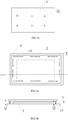
- FIG. 1a is a schematic top view (in this drawing, the supported component shields the pressure distribution plate, and in order to illustrate the pressure distribution plate, the supported component is shown with trasparency) of the support apparatus according to the embodiments of the present disclosure
- FIG. 1b is a schematic sectional view taken in a direction A-A1 in FIG. 1a
- the support apparatus includes: the support substrate 1, the support substrate having the first main surface 11 facing the supported component 2 and the second main surface 12 positioned on the side opposite to the first main surface 11; and the pressure distribution plate 3, the pressure distribution plate 3 being arranged on the first main surface 11 of the support substrate 1 and positioned between the support substrate 1 and the supported component 2.
- the pressure distribution plate 3 moves towards the direction away from the support substrate 1 so as to bring the supported component 2 to be separated from the support substrate 1.
- the pressure distribution plate is clamped by a manipulator, and the pressure distribution plate 3 is bringn to move towards the side away from the support substrate.
- the pressure distribution plate is jacked up by a jacking mechanism from a side of the pressure distribution plate 3 close to the support substrate 1.
- the support substrate 1 is provided with a first through hole 13 running through the first main surface 11 and the second main surface 12 in a thickness direction of the support substrate 1.
- the support apparatus further includes a separation device 4, and the separation device 4 includes a first protrusion 42.
- the first protrusion 42 passes through the first through hole 13 and presses against the pressure distribution plate 3 to jack up the pressure distribution plate 3, so that the pressure distribution plate 3 brings the supported component 2 to be separated from the support substrate 1.
- the separation device 4 further includes a first base 41, and the first protrusion 42 is arranged on the first base 41.
- first base 41 and the first protrusion 42 are not limited to the structures in the drawing, as long as the first protrusion 42 can be guaranteed to pass through the first through hole 13 and jack up the pressure distribution plate 3 and the supported component 2 positioned on the pressure distribution plate 3.
- a portion of the first protrusion 42 protruding from the first through hole 13 presses against the pressure distribution plate 3 so as to bring the pressure distribution plate 3 to separate the supported component from the support substrate. Therefore, a length of the first protrusion 42, for example, is greater than a depth of the first through hole 13.
- the first base 41 is of a plate-shaped structure
- the first protrusion 42 is perpendicularly arranged on a surface of the first base 41, which faces the support substrate 1, and corresponds to the first through hole 13 on the support substrate 1.
- the first through hole 13 is perpendicularly arranged along the thickness direction of the support substrate 1.
- FIG. 3 shows a schematic view of separating the supported component from the support substrate.
- the separation device 4 is moved along a direction towards the support substrate 1, so that the first protrusion 42 of the separation device 4 passes through the first through hole 13 and contacts with the pressure distribution plate 3; then the separation device 4 is continuously moved and the pressure distribution plate 3 is jacked up, so that the pressure distribution plate 3 brings the supported component 2 positioned thereon to move so as to enable the supported component 2 and the support substrate 1 to be separated from each other.
- there are a plurality of the first protrusions 42 there are a plurality of the first through holes 13, and the first protrusions 42 and the first through holes 13 correspond to each other one to one.
- a force bearing point can be positioned on the pressure distribution plate 3 so as to avoid damage caused by a case that the supported component 2 suffers a force directly.
- the supported component 2 for example is conveyed to a next process by a conveyor device (e.g., a manipulator), and the separation device 4 moves along a direction away from the support substrate 1 to enable the first protrusion 42 to exit the first through hole 13 and rearrange the pressure distribution plate 3 on the support substrate 1.
- a conveyor device e.g., a manipulator
- a positioning element 31 and/or a binding element 32 which corresponds to the first through hole 13 in position, is arranged on a surface of the pressure distribution plate 3 facing the support substrate 1, so that after the first protrusion 42 passes through the first through hole 13, positioning of the first protrusion 42 can be carried out by the positioning element 31 and/or the binding element 32, thereby preventing relative movement between the first protrusion 41 and the pressure distribution plate 3 in the process of separating the supported component 2 from the support substrate 1 and ensuring stability of separation.
- the positioning element 31 is a blind hole extending from a surface of the pressure distribution plate 3 facing the support substrate 1 toward a surface of the pressure distribution plate 3 away from the support substrate 1.
- the "blind hole” means a hole extending from the surface of the pressure distribution plate 3 facing the support substrate 1 toward the surface of the pressure distribution plate 3 away from the support substrate 1 without passing through the pressure distribution plate 3.
- a number and positions of the blind holes correspond to a number and positions of the first through holes.
- the positioning elements 31 correspond to the first protrusions 41 (or, the first through holes 13) one to one, that is, the blind holes correspond to the first protrusions 41 (or, the first through holes 13) one to one.
- another binding element 43 is arranged on the first protrusion 42.
- the binding element 32 of the pressure distribution plate 3 binds with the another binding element 43 on the first protrusion 42, so that the first protrusion 42 and the pressure distribution plate 3 are fixed to each other, thereby ensuring stability of separation.
- a plurality of the binding elements 32 are provided, a plurality of the another binding elements 43 are provided, and the binding elements 32 of the pressure distribution plate 3 correspond to the binding elements 43 on the first protrusion portions 42 one to one.
- the binding element 31 on the pressure distribution plate 3 and the another binding element 43 on the first protrusion 42 bind with each other by a magnetic adsorption force, so that the first protrusion 42 and the pressure distribution plate 3 can be easily separated during the first protrusion 42 exits the first through hole 13.
- the another binding element 43 on the first protrusion 42 is a magnet, and the binding element 32 on the pressure distribution plate 3 is a ferromagnetic material; or the binding element 32 on the pressure distribution plate 3 is a magnet, and the another binding element 43 on the first protrusion 42 is a ferromagnetic material; or the another binding element 43 on the first protrusion 42 and the binding element 32 on the pressure distribution plate 3 are magnets attracting each other, i.e., at least portions of the another binding element 43 and the binding element 32, which contact with each other, are opposite in magnetism.
- both the positioning element 31 and the binding element 32 are arranged on the pressure distribution plate 3.
- the blind hole 31 is formed on the pressure distribution plate 3, and meanwhile, the magnet or the ferromagnetic material is arranged at the bottom of the blind hole 31; and correspondingly, the another binding element 43 on the first protrusion 42 is set as the ferromagnetic material or the magnet, so that the first protrusion 42 is limited in the blind hole and is adsorbed to the pressure distribution plate by the magnetic force after passing through the first through hole 13, thereby further improving stability of the separation process.
- a positioning effect of the positioning element and a binding effect of the binding element are simultaneously achieved, so that the process of separating the supported component from the support substrate is more stable.
- a support element is arranged on the first main surface of the support substrate, and the support element supports the supported component.
- the support element 14 is arranged on the first main surface 11 of the support substrate 1.
- the support element 14, for example, is uniformly arranged along the edge of the support substrate 1.
- the support element is provided with an adhering portion, and the adhering portion adheres the supported component to the support substrate.
- the adhering portion is arranged at a side of the support element 14, which is away from the first main surface 11. By arranging the adhering portion, the supported component is more firmly arranged on the support substrate.
- FIG. 6b is a schematic sectional view of the support apparatus according to the embodiments of the present disclosure, in which the support element is arranged on the support substrate.
- a height h1 of the support element 14 in the direction from the support substrate 1 to the supported component 2 is greater than a thickness h2 of the pressure distribution plate 3.
- the height of the support element 14 in a thickness direction of the support substrate 1 is greater than a thickness of the pressure distribution plate 3, so that the supported component 2 is placed on the support element 14 during the support substrate 1 bears the supported component.
- the supported component 2 does not contact with the pressure distribution plate 3.
- a first fixing element 15 is arranged on the first main surface 11 of the support substrate 1; a second fixing element 33, which corresponds to the first fixing element 15 in position, is arranged on the surface of the pressure distribution plate 3 facing the support substrate 1; and the first fixing element 15 and the second fixing element 33 bind with each other to fix the pressure distribution plate 3 to the support substrate.
- the first fixing element 15 and the second fixing element 33 bind with each other by a magnetic adsorption force, so that the pressure distribution plate 3 and the support substrate 1 can be easily separated.
- the first fixing element 15 is a ferromagnetic material, and the second fixing element 33 is a magnet; or the first fixing element 15 is a magnet, and the second fixing element 33 is a ferromagnetic material; or the first fixing element 15 and the second fixing element 33 are magnets attracting each other, i.e., at least portions of the first fixing element 15 and the second fixing element 33, which contact with each other, are opposite in magnet polarity.
- the pressure distribution plate 3 and the support substrate 1 By enabling the pressure distribution plate 3 and the support substrate 1 to bind with each other by the first fixing element 15 and the second fixing element 33, the pressure distribution plate 3 and the support substrate 1 arc fixed to each other during the pressure distribution plate 3 is placed on the support substrate 1.
- the first fixing element 15 and the second fixing element 33 bind with each other by the magnetic adsorption force, the pressure distribution plate 3 and the support substrate can be easily separated in the separation process.
- the support substrate 1 is further provided with a second through hole 16 running through the first main surface and the second main surface; the pressure distribution plate 3 is provided with a through hole 34 corresponding to the second through hole 16 in position; and the support apparatus further comprises a transfer device 5, and the transfer device 5 includes a second protrusion 52.
- the second protrusion 52 of the transfer device 5 passes through the second through hole 16 of the support substrate 1 and the through hole 34 of the pressure distribution plate 3, the supported component 2 is placed on the second protrusion 52, and then the second protrusion 52 is controlled to move downwards to bring the supported component 2 onto the support substrate 1.
- the transfer device 5 further includes a second base 51, and the second protrusion 52 is arranged on the second base 51.
- the second base 51 is of a plate-shaped structure
- the second protrusion 52 is arranged on a surface of the plate-shaped structure, which faces the support substrate 1.
- the second protrusion 52 corresponds to the through hole 34 of the pressure distribution plate 3 and the second through hole 16 of the support substrate 1 in position.
- the second protrusion 52 passes through both the second through hole 16 of the support substrate 1 and the through hole 34 of the pressure distribution plate 3, i.e., a length of the second protrusion portion 52 is greater than a sum of a depth of the second through hole 16 of the support substrate 1 and a depth of the through hole 34 of the pressure distribution plate 3, so that after the second protrusion 52 passes through the second through hole 16 of the support substrate 1 and the through hole 34 of the pressure distribution plate 3, the supported component 2 is moved onto the support substrate 1.
- the second through hole 16 of the support substrate 1 is perpendicularly formed along the thickness direction of the support substrate 1; for example, the through hole 34 of the pressure distribution plate 3 is perpendicularly formed along the thickness direction of the pressure distribution plate 3; for example, the second protrusion 42 is arranged perpendicularly on the second base 51, so that the second protrusion 42 can more easily pass through the second through hole 16 of the support substrate 1 and the through hole 34 of the pressure distribution plate 3, thereby transferring the supported component 2 onto the support substrate 1.
- the second protrusion 52 includes an adsorption element arranged at an end portion of the second protrusion 52.
- the adsorption element for example, is a vacuum adsorption head so as to effectively adsorb the supported component (e.g., the display substrate) and move the supported component onto the support substrate.
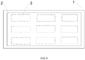
- one or more of the pressure distribution plates are arranged between the supported component and the support substrate; in other words, for one supported component, one or more pressure distribution plates may be arranged.
- a plurality of the pressure distribution plates are uniformly arranged on the first main surface of the support substrate (six pressure distribution plates are shown in the drawing). The embodiments of the present disclosure do not limit the number of the pressure distribution plates.
- the embodiments of the present disclosure provide a support method, and the support method includes: providing a support substrate and a pressure distribution plate, the support substrate having a first main surface facing a supported component and a second main surface positioned on a side opposite to the first main surface, wherein the pressure distribution plate is arranged on the first main surface of the support substrate and the supported component is arranged above the pressure distribution plate; and moving the pressure distribution plate towards a direction away from the support substrate so as to bring the supported component to be separated from the support substrate.
- the support substrate is provided with the first through hole running through the first main surface and the second main surface in a thickness direction of the support substrate; and the moving the pressure distribution plate towards the direction away from the support substrate so as to bring the supported component to be separated from the support substrate includes: providing the separation device, the separation device including the first protrusion; and moving the first protrusion to pass through the first through hole and press against the pressure distribution plate to jack up the pressure distribution plate, so that the pressure distribution plate brings the supported component to be separated from the support substrate.
- the positioning element and/or the binding element which corresponds to the first through hole in position, is arranged on a surface of the pressure distribution plate facing the support substrate; and the first protrusion, after passing through the first through hole, binds with the pressure distribution plate by the positioning element and/or the binding element, so that in the process that the first protrusion jacks up the pressure distribution plate, the first protrusion and the pressure distribution plate are fixed to each other.
- the positioning element and/or the binding element on the pressure distribution plate to correspond to the first protrusion, the separation process of the supported component and the support substrate can be more stable.
- the positioning element is a blind hole extending from the side of the pressure distribution plate, which faces the support substrate, to the side of the pressure distribution plate, which is away from the support substrate.
- the first protrusion presses against the blind hole after passing through the first through hole of the support substrate so as to avoid relative movement between the first protrusion and the pressure distribution plate in the separation process, thereby further improving stability of the separation process.
- the another binding element is arranged on the first protrusion; and the binding element on the pressure distribution plate binds with the another binding element on the first protrusion, so that in the process that the first protrusion jacks up the pressure distribution plate, the first protrusion and the pressure distribution plate are fixed to each other.
- the binding element on the pressure distribution plate and the another binding element on the first protrusion an effect that the first protrusion and the pressure distribution plate are fixed to each other can be better, and stability of the separation process is improved.
- the binding element on the pressure distribution plate binds with the another binding element on the first protrusion by a magnetic adsorption force.
- the pressure distribution plate binds with the first protrusion in a mode of attracting each other by the magnetic adsorption force, so that not only is the structure simple, but also mutual positioning of the pressure distribution plate and the first protrusion can be rapidly implemented, and separation efficiency is improved.
- a support element is arranged on the first main surface of the support substrate, and the support element supports the supported component.
- the support element is provided with the adhering portion, and the adhering portion adheres the supported component to the support substrate.
- the adhering portion By arranging the adhering portion on the support element, the supported component can be stably placed on the support substrate.
- the height of the support element in the direction from the support substrate to the supported component is greater than the thickness of the pressure distribution plate.
- the support substrate is provided with the second through hole running through the first main surface and the second main surface;
- the pressure distribution plate is provided with the through hole corresponding to the second through hole in position; and the support method further includes: providing the transfer device, the transfer device including the second protrusion; and placing the supported component on the second protrusion after the second protrusion passes through the second through hole of the support substrate and the through hole of the pressure distribution plate, and then moving the second protrusion so as to move the supported component placed on the second protrusion onto the support substrate.
Landscapes
- Container, Conveyance, Adherence, Positioning, Of Wafer (AREA)
- Magnetic Bearings And Hydrostatic Bearings (AREA)
- Electroluminescent Light Sources (AREA)
Abstract
Description
- Embodiments of the present disclosure relate to a support apparatus and a support method.
- In the preparation process of a display substrate, various treatments, e.g., evaporation deposition, sputtering and the like, need to be carried out on the display substrate. During the various treatments are carried out, the display substrate generally is supported by a support substrate. After the treatments are finished, the support substrate and the display substrate are conveyed to a separation chamber together, and the display substrate is jacked up by a lifting pin base so as to separate the display substrate from the support substrate. In the separating process, due to a small contact area of the display substrate and a lifting pin of the lifting pin base, the display substrate bears a pressure at a position where the display substrate is in contact with the lifting pin, such that the display substrate is easy to be damaged and product defects are caused, and particularly for a large-sized display substrate, a severe deformation may be caused.
- According to embodiments of the disclosure, a support apparatus is provided. The support apparatus comprises: a support substrate, for bearing a supported component, the support substrate having a first main surface facing the supported component and a second main surface positioned on a side opposite to the first main surface; and a pressure distribution plate, arranged on the first main surface of the support substrate and positioned between the support substrate and the supported component, wherein the pressure distribution plate is configured to bring the supported component to be separated from the support substrate.
- For example, the support substrate is provided with a first through hole running through the first main surface and the second main surface in a thickness direction of the support substrate; the support apparatus further comprises a separation device, the separation device including a first protrusion; and the first protrusion is configured to pass through the first through hole and jack up the pressure distribution plate.
- For example, a positioning element and/or a binding element, which corresponds to the first through hole in position, is arranged on a surface of the pressure distribution plate facing the support substrate.
- For example, the positioning element is a blind hole extending from a side of the pressure distribution plate facing the support substrate to a side of the pressure distribution plate away from the support substrate.
- For example, another binding element is arranged on the first protrusion; and in the process that the first protrusion jacks up the pressure distribution plate, the binding element of the pressure distribution plate and the another binding element of the first protrusion binds with each other, so that the first protrusion and the pressure distribution plate are fixed to each other.
- For example, the binding element of the pressure distribution plate and the another binding element of the first protrusion bind with each other by a magnetic adsorption force.
- For example, a support element is arranged on the first main surface of the support substrate, and the support element supports the supported component.
- For example, the support element is provided with an adhering portion, and the adhering portion adheres the supported component to the support substrate.
- For example, a height of the support element in a direction from the support substrate to the supported component is greater than a thickness of the pressure distribution plate.
- For example, a first fixing element is arranged on the first main surface of the support substrate; a second fixing element, which corresponds to the first fixing element in position, is arranged on a surface of the pressure distribution plate, which faces the support substrate; and the first fixing element and the second fixing element bind with each other to fix the pressure distribution plate to the support substrate.
- For example, the first fixing element and the second fixing element bind with each other by a magnetic adsorption force.
- For example, the support substrate is provided with a second through hole running through the first main surface and the second main surface; the pressure distribution plate is provided with a through hole corresponding to the second through hole in position; the support apparatus further comprises a transfer device, the transfer device including a second protrusion; and the second protrusion is configured to pass through the second through hole of the support substrate and the through hole of the pressure distribution plate.
- For example, the second protrusion includes an adsorption element arranged at an end portion of the second protrusion.
- According to the embodiments of the disclosure, a support method is provided. The method comprises: providing a support substrate for bearing a supported component, the support substrate having a first main surface facing the supported component and a second main surface positioned on a side opposite to the first main surface; providing a pressure distribution plate arranged on the first main surface of the support substrate and positioned between the support substrate and the supported component; and moving the pressure distribution plate towards a direction away from the support substrate so as to bring the supported component to be separated from the support substrate.
- For example, the support substrate is provided with a first through hole running through the first main surface and the second main surface in a thickness direction of the support substrate. The moving the pressure distribution plate towards the direction away from the support substrate so as to bring the supported component to be separated from the support substrate includes: providing a separation device, the separation device including a first protrusion; and moving the first protrusion to pass through the first through hole and jack up the pressure distribution plate, so that the pressure distribution plate brings the supported component to be separated from the support substrate.
- For example, a positioning element and/or a binding element, which corresponds to the first through hole in position, is arranged on a surface of the pressure distribution plate facing the support substrate; and the first protrusion, after passing through the first through hole, binds with the pressure distribution plate by the positioning element and/or the binding element, so that in the process that the first protrusion jacks up the pressure distribution plate, the first protrusion and the pressure distribution plate are fixed to each other.
- For example, the support substrate is provided with a second through hole running through the first main surface and the second main surface; the pressure distribution plate is provided with a through hole corresponding to the second through hole in position; and the support method further comprising: providing a transfer device, the transfer device including a second protrusion; and placing the supported component on the second protrusion after the second protrusion passes through the second through hole of the support substrate and the through hole of the pressure distribution plate, and then moving the second protrusion so as to move the supported component placed on the second protrusion onto the support substrate.
- In order to clearly illustrate the technical solution of the embodiments of the disclosure, the drawings of the embodiments will be briefly described in the following; it is obvious that the described drawings are only related to some embodiments of the disclosure and thus are not limitative of the disclosure.
-
FIG. 1a is a schematic top view of a support apparatus according to embodiments of the present disclosure; -
FIG. 1b is a schematic sectional view taken in a direction A-Al inFIG. 1a ; -
FIG. 2a is a structural schematic view of a support substrate with a first through hole according to the embodiments of the present disclosure; -
FIG. 2b is a structural schematic view of a separation device according to the embodiments of the present disclosure; -
FIG. 3 is a schematic view of separating a supported component from the support substrate according to the embodiments of the present disclosure; -
FIG. 4a is a schematic top view of a pressure distribution plate with a blind hole according to the embodiments of the present disclosure; -
FIG. 4b is a schematic side view ofFIG. 4a ; -
FIG. 5a is a schematic view of a first protrusion with another binding element according to the embodiments of the present disclosure; -
FIG. 5b is a schematic view of the pressure distribution plate with a binding element according to the embodiments of the present disclosure; -
FIG. 6a is a schematic top view of the support substrate with a support element according to the embodiments of the present disclosure; -
FIG. 6b is a schematic sectional view taken in a direction C-C1 inFIG. 6a ; -
FIG. 7a is a schematic top view of the support substrate with a first fixing element according to the embodiments of the present disclosure; -
FIG. 7b is a schematic top view of the pressure distribution plate with a second fixing element according to the embodiments of the present disclosure; -
FIG. 8 is a schematic view of transferring the supported component to the support substrate by a transfer device according to the embodiments of the present disclosure; and -
FIG. 9 is a schematic top view of the support substrate with a plurality of pressure distribution plates according to the embodiments of the present disclosure. - In order to make objects, technical details and advantages of the embodiments of the disclosure apparent, the technical solutions of the embodiment will be described in a clearly and fully understandable way in connection with the drawings related to the embodiments of the disclosure. It is obvious that the described embodiments are just a part but not all of the embodiments of the disclosure. Based on the described embodiments herein, those skilled in the art can obtain other embodiment(s), without any inventive work, which should be within the scope of the disclosure.
- In one aspect, embodiments of the present disclosure provide a support apparatus, and the support apparatus includes: a support substrate for bearing a supported component, the support substrate having a first main surface facing the supported component and a second main surface positioned on a side opposite to the first main surface; and a pressure distribution plate arranged on the first main surface of the support substrate and positioned between the support substrate and the supported component. The pressure distribution plate is configured to bring the supported component to be separated from the support substrate. For example, in the process of separating the supported component from the support substrate, the pressure distribution plate moves towards a direction away from the support substrate to bring the supported component to be separated from the support substrate. In the support apparatus according to the embodiments of the present disclosure, by arranging the pressure distribution plate, damage to the supported component in the process of separating the supported component from the support substrate can be avoided, and product yield is improved; and for example, in the case that an external force is applied to separate the supported component from the support substrate, the external force is directly applied to the pressure distribution plate instead of being directly applied to the supported component so as to avoid damage to the supported component. For example, the supported component is a display substrate; in this case, by arranging the pressure distribution plate, damage to the display substrate in the process of separating the display substrate from the support substrate can be avoided, product yield is improved, and particularly for a large-sized display substrate, deformation of the display substrate, which is generated during the display substrate is separated from the support substrate, can be greatly reduced.
- The support apparatus according to the embodiments of the present disclosure will be described in detail below in connection with the drawings.
-
FIG. 1a is a schematic top view (in this drawing, the supported component shields the pressure distribution plate, and in order to illustrate the pressure distribution plate, the supported component is shown with trasparency) of the support apparatus according to the embodiments of the present disclosure; andFIG. 1b is a schematic sectional view taken in a direction A-A1 inFIG. 1a . With reference toFIG. 1a and FIG. 1b , the support apparatus includes: thesupport substrate 1, the support substrate having the firstmain surface 11 facing the supportedcomponent 2 and the secondmain surface 12 positioned on the side opposite to the firstmain surface 11; and thepressure distribution plate 3, thepressure distribution plate 3 being arranged on the firstmain surface 11 of thesupport substrate 1 and positioned between thesupport substrate 1 and the supportedcomponent 2. During the supportedcomponent 2 is separated from thesupport substrate 1, thepressure distribution plate 3 moves towards the direction away from thesupport substrate 1 so as to bring the supportedcomponent 2 to be separated from thesupport substrate 1. For example, the pressure distribution plate is clamped by a manipulator, and thepressure distribution plate 3 is bringn to move towards the side away from the support substrate. For example, the pressure distribution plate is jacked up by a jacking mechanism from a side of thepressure distribution plate 3 close to thesupport substrate 1. - For example, with reference to
FIG. 2a , thesupport substrate 1 is provided with a first throughhole 13 running through the firstmain surface 11 and the secondmain surface 12 in a thickness direction of thesupport substrate 1. With reference toFIG. 2b , the support apparatus further includes aseparation device 4, and theseparation device 4 includes afirst protrusion 42. In the process of separating the supportedcomponent 2 from thesupport substrate 1, thefirst protrusion 42 passes through the first throughhole 13 and presses against thepressure distribution plate 3 to jack up thepressure distribution plate 3, so that thepressure distribution plate 3 brings the supportedcomponent 2 to be separated from thesupport substrate 1. For example, theseparation device 4 further includes afirst base 41, and thefirst protrusion 42 is arranged on thefirst base 41. - It should be noted that specific structures of the
first base 41 and thefirst protrusion 42 are not limited to the structures in the drawing, as long as thefirst protrusion 42 can be guaranteed to pass through the first throughhole 13 and jack up thepressure distribution plate 3 and the supportedcomponent 2 positioned on thepressure distribution plate 3. For example, after thefirst protrusion 42 passes through the first throughhole 13, a portion of thefirst protrusion 42 protruding from the first throughhole 13 presses against thepressure distribution plate 3 so as to bring thepressure distribution plate 3 to separate the supported component from the support substrate. Therefore, a length of thefirst protrusion 42, for example, is greater than a depth of the first throughhole 13. For example, thefirst base 41 is of a plate-shaped structure, and thefirst protrusion 42 is perpendicularly arranged on a surface of thefirst base 41, which faces thesupport substrate 1, and corresponds to the first throughhole 13 on thesupport substrate 1. For example, the first throughhole 13 is perpendicularly arranged along the thickness direction of thesupport substrate 1. By perpendicularly arranging the first protrusion and the first through hole, reliability of the separation process can be improved, and damage to the substrate can be avoided. -
FIG. 3 shows a schematic view of separating the supported component from the support substrate. As shown inFIG. 3 , theseparation device 4 is moved along a direction towards thesupport substrate 1, so that thefirst protrusion 42 of theseparation device 4 passes through the first throughhole 13 and contacts with thepressure distribution plate 3; then theseparation device 4 is continuously moved and thepressure distribution plate 3 is jacked up, so that thepressure distribution plate 3 brings the supportedcomponent 2 positioned thereon to move so as to enable the supportedcomponent 2 and thesupport substrate 1 to be separated from each other. For example, as shown inFIG. 3 , there are a plurality of thefirst protrusions 42, there are a plurality of the first throughholes 13, and thefirst protrusions 42 and the first throughholes 13 correspond to each other one to one. By arranging thepressure distribution plate 3, a force bearing point can be positioned on thepressure distribution plate 3 so as to avoid damage caused by a case that the supportedcomponent 2 suffers a force directly. After the supportedcomponent 2 and thesupport substrate 1 are separated from each other, the supportedcomponent 2 for example is conveyed to a next process by a conveyor device (e.g., a manipulator), and theseparation device 4 moves along a direction away from thesupport substrate 1 to enable thefirst protrusion 42 to exit the first throughhole 13 and rearrange thepressure distribution plate 3 on thesupport substrate 1. - For example, a
positioning element 31 and/or abinding element 32, which corresponds to the first throughhole 13 in position, is arranged on a surface of thepressure distribution plate 3 facing thesupport substrate 1, so that after thefirst protrusion 42 passes through the first throughhole 13, positioning of thefirst protrusion 42 can be carried out by thepositioning element 31 and/or thebinding element 32, thereby preventing relative movement between thefirst protrusion 41 and thepressure distribution plate 3 in the process of separating the supportedcomponent 2 from thesupport substrate 1 and ensuring stability of separation. - For example, with reference to
FIG. 4a and FIG. 4b , thepositioning element 31 is a blind hole extending from a surface of thepressure distribution plate 3 facing thesupport substrate 1 toward a surface of thepressure distribution plate 3 away from thesupport substrate 1. The "blind hole" means a hole extending from the surface of thepressure distribution plate 3 facing thesupport substrate 1 toward the surface of thepressure distribution plate 3 away from thesupport substrate 1 without passing through thepressure distribution plate 3. By arranging the blind hole, for example, thefirst protrusion 41 of theseparation device 4 presses against the blind hole after passing through the first throughhole 13 to avoid relative movement between thefirst protrusion 41 and thepressure distribution plate 3 so as to improve stability of the separation process. It should be noted that inFIG. 4a and FIG. 4b , two rows of positioning blind holes of which the number is six in total are shown, but the embodiments of the present disclosure are not limited thereto. For example, a number and positions of the blind holes correspond to a number and positions of the first through holes. For example, thepositioning elements 31 correspond to the first protrusions 41 (or, the first through holes 13) one to one, that is, the blind holes correspond to the first protrusions 41 (or, the first through holes 13) one to one. - For example, with reference to
FIG. 5a andFIG. 5b , another bindingelement 43 is arranged on thefirst protrusion 42. In the process that thefirst protrusion 42 jacks up thepressure distribution plate 3, the bindingelement 32 of thepressure distribution plate 3 binds with the another bindingelement 43 on thefirst protrusion 42, so that thefirst protrusion 42 and thepressure distribution plate 3 are fixed to each other, thereby ensuring stability of separation. For example, a plurality of thebinding elements 32 are provided, a plurality of the anotherbinding elements 43 are provided, and thebinding elements 32 of thepressure distribution plate 3 correspond to thebinding elements 43 on thefirst protrusion portions 42 one to one. - For example, the binding
element 31 on thepressure distribution plate 3 and the another bindingelement 43 on thefirst protrusion 42 bind with each other by a magnetic adsorption force, so that thefirst protrusion 42 and thepressure distribution plate 3 can be easily separated during thefirst protrusion 42 exits the first throughhole 13. For example, the another bindingelement 43 on thefirst protrusion 42 is a magnet, and thebinding element 32 on thepressure distribution plate 3 is a ferromagnetic material; or thebinding element 32 on thepressure distribution plate 3 is a magnet, and the another bindingelement 43 on thefirst protrusion 42 is a ferromagnetic material; or the another bindingelement 43 on thefirst protrusion 42 and thebinding element 32 on thepressure distribution plate 3 are magnets attracting each other, i.e., at least portions of the another bindingelement 43 and thebinding element 32, which contact with each other, are opposite in magnetism. By enabling the another bindingelement 43 on thefirst protrusion 42 and thebinding element 32 on thepressure distribution plate 3 to bind with each other by the magnetic adsorption force, the separation process of the supported component and the support substrate can be more stable. - For example, both the
positioning element 31 and thebinding element 32 are arranged on thepressure distribution plate 3. Further, for example, theblind hole 31 is formed on thepressure distribution plate 3, and meanwhile, the magnet or the ferromagnetic material is arranged at the bottom of theblind hole 31; and correspondingly, the another bindingelement 43 on thefirst protrusion 42 is set as the ferromagnetic material or the magnet, so that thefirst protrusion 42 is limited in the blind hole and is adsorbed to the pressure distribution plate by the magnetic force after passing through the first throughhole 13, thereby further improving stability of the separation process. In other words, a positioning effect of the positioning element and a binding effect of the binding element are simultaneously achieved, so that the process of separating the supported component from the support substrate is more stable. - For example, a support element is arranged on the first main surface of the support substrate, and the support element supports the supported component. With reference to
FIG. 6a , thesupport element 14 is arranged on the firstmain surface 11 of thesupport substrate 1. Thesupport element 14, for example, is uniformly arranged along the edge of thesupport substrate 1. - For example, the support element is provided with an adhering portion, and the adhering portion adheres the supported component to the support substrate. For example, the adhering portion is arranged at a side of the
support element 14, which is away from the firstmain surface 11. By arranging the adhering portion, the supported component is more firmly arranged on the support substrate. - For example, a height of the support element in a direction from the support substrate to the supported component is greater than a thickness of the pressure distribution plate.
FIG. 6b is a schematic sectional view of the support apparatus according to the embodiments of the present disclosure, in which the support element is arranged on the support substrate. With reference toFIG. 6b , a height h1 of thesupport element 14 in the direction from thesupport substrate 1 to the supportedcomponent 2 is greater than a thickness h2 of thepressure distribution plate 3. In other words, the height of thesupport element 14 in a thickness direction of thesupport substrate 1 is greater than a thickness of thepressure distribution plate 3, so that the supportedcomponent 2 is placed on thesupport element 14 during thesupport substrate 1 bears the supported component. For example, as shown inFIG. 6b , during thesupport substrate 1 bears the supported component, the supportedcomponent 2 does not contact with thepressure distribution plate 3. - For example, with reference to
FIG. 7a and FIG. 7b , afirst fixing element 15 is arranged on the firstmain surface 11 of thesupport substrate 1; asecond fixing element 33, which corresponds to the first fixingelement 15 in position, is arranged on the surface of thepressure distribution plate 3 facing thesupport substrate 1; and the first fixingelement 15 and thesecond fixing element 33 bind with each other to fix thepressure distribution plate 3 to the support substrate. - For example, the first fixing
element 15 and thesecond fixing element 33 bind with each other by a magnetic adsorption force, so that thepressure distribution plate 3 and thesupport substrate 1 can be easily separated. For example, the first fixingelement 15 is a ferromagnetic material, and thesecond fixing element 33 is a magnet; or the first fixingelement 15 is a magnet, and thesecond fixing element 33 is a ferromagnetic material; or the first fixingelement 15 and thesecond fixing element 33 are magnets attracting each other, i.e., at least portions of the first fixingelement 15 and thesecond fixing element 33, which contact with each other, are opposite in magnet polarity. By enabling thepressure distribution plate 3 and thesupport substrate 1 to bind with each other by the first fixingelement 15 and thesecond fixing element 33, thepressure distribution plate 3 and thesupport substrate 1 arc fixed to each other during thepressure distribution plate 3 is placed on thesupport substrate 1. In addition, in a case that the first fixingelement 15 and thesecond fixing element 33 bind with each other by the magnetic adsorption force, thepressure distribution plate 3 and the support substrate can be easily separated in the separation process. - For example, with reference to
FIG. 8 , thesupport substrate 1 is further provided with a second throughhole 16 running through the first main surface and the second main surface; thepressure distribution plate 3 is provided with a throughhole 34 corresponding to the second throughhole 16 in position; and the support apparatus further comprises atransfer device 5, and thetransfer device 5 includes asecond protrusion 52. With reference toFIG. 8 , in the process of placing the supportedcomponent 2 on thesupport substrate 1, thesecond protrusion 52 of thetransfer device 5 passes through the second throughhole 16 of thesupport substrate 1 and the throughhole 34 of thepressure distribution plate 3, the supportedcomponent 2 is placed on thesecond protrusion 52, and then thesecond protrusion 52 is controlled to move downwards to bring the supportedcomponent 2 onto thesupport substrate 1. After the supportedcomponent 2 is moved onto thesupport substrate 1, thesecond protrusion 52 is continuously moved downwards so as to exit the second throughhole 16 of thesupport substrate 1 and the throughhole 34 of thepressure distribution plate 3. For example, thetransfer device 5 further includes asecond base 51, and thesecond protrusion 52 is arranged on thesecond base 51. - For example, the
second base 51 is of a plate-shaped structure, and thesecond protrusion 52 is arranged on a surface of the plate-shaped structure, which faces thesupport substrate 1. Thesecond protrusion 52 corresponds to the throughhole 34 of thepressure distribution plate 3 and the second throughhole 16 of thesupport substrate 1 in position. Thesecond protrusion 52 passes through both the second throughhole 16 of thesupport substrate 1 and the throughhole 34 of thepressure distribution plate 3, i.e., a length of thesecond protrusion portion 52 is greater than a sum of a depth of the second throughhole 16 of thesupport substrate 1 and a depth of the throughhole 34 of thepressure distribution plate 3, so that after thesecond protrusion 52 passes through the second throughhole 16 of thesupport substrate 1 and the throughhole 34 of thepressure distribution plate 3, the supportedcomponent 2 is moved onto thesupport substrate 1. With further reference toFIG. 8 , for example, the second throughhole 16 of thesupport substrate 1 is perpendicularly formed along the thickness direction of thesupport substrate 1; for example, the throughhole 34 of thepressure distribution plate 3 is perpendicularly formed along the thickness direction of thepressure distribution plate 3; for example, thesecond protrusion 42 is arranged perpendicularly on thesecond base 51, so that thesecond protrusion 42 can more easily pass through the second throughhole 16 of thesupport substrate 1 and the throughhole 34 of thepressure distribution plate 3, thereby transferring the supportedcomponent 2 onto thesupport substrate 1. - For example, the
second protrusion 52 includes an adsorption element arranged at an end portion of thesecond protrusion 52. The adsorption element, for example, is a vacuum adsorption head so as to effectively adsorb the supported component (e.g., the display substrate) and move the supported component onto the support substrate. - It should be noted that, for example, one or more of the pressure distribution plates are arranged between the supported component and the support substrate; in other words, for one supported component, one or more pressure distribution plates may be arranged. With reference to
FIG. 9 , for example, a plurality of the pressure distribution plates are uniformly arranged on the first main surface of the support substrate (six pressure distribution plates are shown in the drawing). The embodiments of the present disclosure do not limit the number of the pressure distribution plates. - In another aspect, the embodiments of the present disclosure provide a support method, and the support method includes: providing a support substrate and a pressure distribution plate, the support substrate having a first main surface facing a supported component and a second main surface positioned on a side opposite to the first main surface, wherein the pressure distribution plate is arranged on the first main surface of the support substrate and the supported component is arranged above the pressure distribution plate; and moving the pressure distribution plate towards a direction away from the support substrate so as to bring the supported component to be separated from the support substrate.
- For example, the support substrate is provided with the first through hole running through the first main surface and the second main surface in a thickness direction of the support substrate; and the moving the pressure distribution plate towards the direction away from the support substrate so as to bring the supported component to be separated from the support substrate includes: providing the separation device, the separation device including the first protrusion; and moving the first protrusion to pass through the first through hole and press against the pressure distribution plate to jack up the pressure distribution plate, so that the pressure distribution plate brings the supported component to be separated from the support substrate.
- For example, the positioning element and/or the binding element, which corresponds to the first through hole in position, is arranged on a surface of the pressure distribution plate facing the support substrate; and the first protrusion, after passing through the first through hole, binds with the pressure distribution plate by the positioning element and/or the binding element, so that in the process that the first protrusion jacks up the pressure distribution plate, the first protrusion and the pressure distribution plate are fixed to each other. By arranging the positioning element and/or the binding element on the pressure distribution plate to correspond to the first protrusion, the separation process of the supported component and the support substrate can be more stable.
- For example, the positioning element is a blind hole extending from the side of the pressure distribution plate, which faces the support substrate, to the side of the pressure distribution plate, which is away from the support substrate. For example, the first protrusion presses against the blind hole after passing through the first through hole of the support substrate so as to avoid relative movement between the first protrusion and the pressure distribution plate in the separation process, thereby further improving stability of the separation process.
- For example, the another binding element is arranged on the first protrusion; and the binding element on the pressure distribution plate binds with the another binding element on the first protrusion, so that in the process that the first protrusion jacks up the pressure distribution plate, the first protrusion and the pressure distribution plate are fixed to each other. By arranging the binding element on the pressure distribution plate and the another binding element on the first protrusion, an effect that the first protrusion and the pressure distribution plate are fixed to each other can be better, and stability of the separation process is improved.
- For example, the binding element on the pressure distribution plate binds with the another binding element on the first protrusion by a magnetic adsorption force. The pressure distribution plate binds with the first protrusion in a mode of attracting each other by the magnetic adsorption force, so that not only is the structure simple, but also mutual positioning of the pressure distribution plate and the first protrusion can be rapidly implemented, and separation efficiency is improved.
- For example, a support element is arranged on the first main surface of the support substrate, and the support element supports the supported component.
- For example, the support element is provided with the adhering portion, and the adhering portion adheres the supported component to the support substrate. By arranging the adhering portion on the support element, the supported component can be stably placed on the support substrate.
- For example, the height of the support element in the direction from the support substrate to the supported component is greater than the thickness of the pressure distribution plate. By setting the height of the support element and the thickness of the pressure distribution plate, the supported component is supported by the support element during the support substrate bears the supported component.
- For example, the support substrate is provided with the second through hole running through the first main surface and the second main surface; the pressure distribution plate is provided with the through hole corresponding to the second through hole in position; and the support method further includes: providing the transfer device, the transfer device including the second protrusion; and placing the supported component on the second protrusion after the second protrusion passes through the second through hole of the support substrate and the through hole of the pressure distribution plate, and then moving the second protrusion so as to move the supported component placed on the second protrusion onto the support substrate.
- In addition, various modifications above related to structures of the pressure distribution plate and the support substrate of the support apparatus may be adopted in the support method according to the embodiments of the present disclosure, and have corresponding technical effects. The embodiments of the present disclosure do not repeat herein.
- In this specification, terms like "first", "second" are only used to differentiate one entity or operation from another, but are not necessarily used to indicate any practical relationship or order between those entities or operations. Terms such as "include" and "comprise" are open-ended expressions, not exclusive of a case that the included processes, methods and objects also have other elements. It should also be explained that directional or positional relationships shown by terms such as "upper", "lower" are directional or positional relationships shown as in the drawings, which only means to facilitate description of the invention and simplify the description, but do not indicate or imply that the devices or components must have specific directions, or be constructed or operated in the specific directions, and are not limitative of the invention. Unless expressly stipulated or defined, terms "mounted", "connected" and "linked" should be broadly understood, for example, they may be fixedly connected, detachably connected, or integrally connected; may be mechanically connected or electrically connected; or may be directly connected, indirectly connected by a medium, or internally communicated between two components. For those skilled in the art, specific meanings of the words in the present disclosure can be understood according to the actual conditions.
- The foregoing embodiments merely are exemplary embodiments of the disclosure, and not intended to define the scope of the disclosure, and the scope of the disclosure is determined by the appended claims.
- The present application claims priority of the Chinese Patent Application No.
201610365366.8 filed on May 27, 2016
Claims (17)
- A support apparatus, comprising:a support substrate, for bearing a supported component, the support substrate having a first main surface facing the supported component and a second main surface positioned on a side opposite to the first main surface; anda pressure distribution plate, arranged on the first main surface of the support substrate and positioned between the support substrate and the supported component,wherein the pressure distribution plate is configured to bring the supported component to be separated from the support substrate.
- The support apparatus according to claim 1, wherein
the support substrate is provided with a first through hole running through the first main surface and the second main surface in a thickness direction of the support substrate;
the support apparatus further comprises a separation device, the separation device including a first protrusion; and
the first protrusion is configured to pass through the first through hole and jack up the pressure distribution plate. - The support apparatus according to claim 2, wherein a positioning element and/or a binding element, which corresponds to the first through hole in position, is arranged on a surface of the pressure distribution plate facing the support substrate.
- The support apparatus according to claim 3, wherein the positioning element is a blind hole extending from a side of the pressure distribution plate facing the support substrate to a side of the pressure distribution plate away from the support substrate.
- The support apparatus according to claim 3, wherein
another binding element is arranged on the first protrusion; and
in the process that the first protrusion jacks up the pressure distribution plate, the binding element of the pressure distribution plate and the another binding element of the first protrusion binds with each other, so that the first protrusion and the pressure distribution plate are fixed to each other. - The support apparatus according to claim 5, wherein the binding element of the pressure distribution plate and the another binding element of the first protrusion bind with each other by a magnetic adsorption force.
- The support apparatus according to any one of claims 1 to 6, wherein
a support element is arranged on the first main surface of the support substrate, and the support element supports the supported component. - The support apparatus according to claim 7, wherein the support element is provided with an adhering portion, and the adhering portion adheres the supported component to the support substrate.
- The support apparatus according to claim 7, wherein a height of the support element in a direction from the support substrate to the supported component is greater than a thickness of the pressure distribution plate.
- The support apparatus according to any one of claims 1 to 6, wherein
a first fixing element is arranged on the first main surface of the support substrate;
a second fixing element, which corresponds to the first fixing element in position, is arranged on a surface of the pressure distribution plate, which faces the support substrate; and
the first fixing element and the second fixing element bind with each other to fix the pressure distribution plate to the support substrate. - The support apparatus according to claim 10, wherein the first fixing element and the second fixing element bind with each other by a magnetic adsorption force.
- The support apparatus according to any one of claims 1 to 6, wherein
the support substrate is provided with a second through hole running through the first main surface and the second main surface;
the pressure distribution plate is provided with a through hole corresponding to the second through hole in position;
the support apparatus further comprises a transfer device, the transfer device including a second protrusion; and
the second protrusion is configured to pass through the second through hole of the support substrate and the through hole of the pressure distribution plate. - The support apparatus according to claim 12, wherein the second protrusion includes an adsorption element arranged at an end portion of the second protrusion.
- A support method, comprising:providing a support substrate for bearing a supported component, the support substrate having a first main surface facing the supported component and a second main surface positioned on a side opposite to the first main surface;providing a pressure distribution plate arranged on the first main surface of the support substrate and positioned between the support substrate and the supported component; andmoving the pressure distribution plate towards a direction away from the support substrate so as to bring the supported component to be separated from the support substrate.
- The support method according to claim 14, wherein
the support substrate is provided with a first through hole running through the first main surface and the second main surface in a thickness direction of the support substrate; and
the moving the pressure distribution plate towards the direction away from the support substrate so as to bring the supported component to be separated from the support substrate includes:providing a separation device, the separation device including a first protrusion; andmoving the first protrusion to pass through the first through hole and jack up the pressure distribution plate, so that the pressure distribution plate brings the supported component to be separated from the support substrate. - The support method according to claim 15, wherein a positioning element and/or a binding element, which corresponds to the first through hole in position, is arranged on a surface of the pressure distribution plate facing the support substrate; and the first protrusion, after passing through the first through hole, binds with the pressure distribution plate by the positioning element and/or the binding element, so that in the process that the first protrusion jacks up the pressure distribution plate, the first protrusion and the pressure distribution plate are fixed to each other.
- The support method according to any one of claims 14 to 16, wherein
the support substrate is provided with a second through hole running through the first main surface and the second main surface;
the pressure distribution plate is provided with a through hole corresponding to the second through hole in position; and
the support method further comprising:providing a transfer device, the transfer device including a second protrusion; andplacing the supported component on the second protrusion after the second protrusion passes through the second through hole of the support substrate and the through hole of the pressure distribution plate, and then moving the second protrusion so as to move the supported component placed on the second protrusion onto the support substrate.
Applications Claiming Priority (2)
| Application Number | Priority Date | Filing Date | Title |
|---|---|---|---|
| CN201610365366.8A CN105845609B (en) | 2016-05-27 | 2016-05-27 | Support equipment and method for supporting |
| PCT/CN2017/075450 WO2017202097A1 (en) | 2016-05-27 | 2017-03-02 | Support apparatus and support method |
Publications (3)
| Publication Number | Publication Date |
|---|---|
| EP3467868A1 true EP3467868A1 (en) | 2019-04-10 |
| EP3467868A4 EP3467868A4 (en) | 2020-03-25 |
| EP3467868B1 EP3467868B1 (en) | 2021-04-28 |
Family
ID=56595676
Family Applications (1)
| Application Number | Title | Priority Date | Filing Date |
|---|---|---|---|
| EP17761425.2A Active EP3467868B1 (en) | 2016-05-27 | 2017-03-02 | Support apparatus and support method |
Country Status (4)
| Country | Link |
|---|---|
| US (1) | US10354906B2 (en) |
| EP (1) | EP3467868B1 (en) |
| CN (1) | CN105845609B (en) |
| WO (1) | WO2017202097A1 (en) |
Families Citing this family (4)
| Publication number | Priority date | Publication date | Assignee | Title |
|---|---|---|---|---|
| CN104853017B (en) * | 2015-04-21 | 2018-03-23 | 浙江吉利控股集团有限公司 | Charger baby and combined type terminal device |
| CN105845609B (en) * | 2016-05-27 | 2019-08-20 | 京东方科技集团股份有限公司 | Support equipment and method for supporting |
| JP7360828B2 (en) * | 2019-07-02 | 2023-10-13 | キヤノントッキ株式会社 | Magnetic adsorption mechanisms, vapor deposition equipment, and electronic device manufacturing equipment |
| EP4299520A4 (en) * | 2021-03-31 | 2024-10-02 | Denka Company Limited | SILICON DIOXIDE POWDER |
Family Cites Families (10)
| Publication number | Priority date | Publication date | Assignee | Title |
|---|---|---|---|---|
| EP1174910A3 (en) * | 2000-07-20 | 2010-01-06 | Applied Materials, Inc. | Method and apparatus for dechucking a substrate |
| JP4476764B2 (en) * | 2004-03-26 | 2010-06-09 | 富士フイルム株式会社 | Substrate bonding apparatus and method |
| US20050223986A1 (en) * | 2004-04-12 | 2005-10-13 | Choi Soo Y | Gas diffusion shower head design for large area plasma enhanced chemical vapor deposition |
| US20090181553A1 (en) * | 2008-01-11 | 2009-07-16 | Blake Koelmel | Apparatus and method of aligning and positioning a cold substrate on a hot surface |
| JP5310512B2 (en) * | 2009-12-02 | 2013-10-09 | 東京エレクトロン株式会社 | Substrate processing equipment |
| JP6148532B2 (en) * | 2013-05-08 | 2017-06-14 | 東京応化工業株式会社 | Pasting device and pasting method |
| CN105575863B (en) | 2014-11-10 | 2019-02-22 | 中微半导体设备(上海)有限公司 | Plasma processing apparatus, substrate discharge mechanism and method |
| CN105810628A (en) * | 2014-12-31 | 2016-07-27 | 南京瀚宇彩欣科技有限责任公司 | Substrate supporting device |
| CN104617017A (en) * | 2015-01-12 | 2015-05-13 | 合肥京东方光电科技有限公司 | Base plate supporting device and method and vacuum drying device |
| CN105845609B (en) | 2016-05-27 | 2019-08-20 | 京东方科技集团股份有限公司 | Support equipment and method for supporting |
-
2016
- 2016-05-27 CN CN201610365366.8A patent/CN105845609B/en not_active Expired - Fee Related
-
2017
- 2017-03-02 WO PCT/CN2017/075450 patent/WO2017202097A1/en not_active Ceased
- 2017-03-02 EP EP17761425.2A patent/EP3467868B1/en active Active
- 2017-03-02 US US15/558,378 patent/US10354906B2/en active Active
Also Published As
| Publication number | Publication date |
|---|---|
| US10354906B2 (en) | 2019-07-16 |
| WO2017202097A1 (en) | 2017-11-30 |
| US20180096876A1 (en) | 2018-04-05 |
| CN105845609B (en) | 2019-08-20 |
| EP3467868A4 (en) | 2020-03-25 |
| EP3467868B1 (en) | 2021-04-28 |
| CN105845609A (en) | 2016-08-10 |
Similar Documents
| Publication | Publication Date | Title |
|---|---|---|
| JP5488966B2 (en) | Ejector | |
| US10354906B2 (en) | Support apparatus and support method | |
| US9039867B2 (en) | Method for detaching a semiconductor chip from a foil | |
| CN107710397B (en) | Substrate holding apparatus, film forming apparatus, and substrate holding method | |
| JP6516664B2 (en) | Substrate holding apparatus, coating apparatus, substrate holding method | |
| KR101479943B1 (en) | The System and Method to Align Substrate and Mask | |
| CN106486394A (en) | Wafer leveling device | |
| KR20150043983A (en) | Substrate holder unit and apparatus for treatmenting substrate having the same | |
| KR102600430B1 (en) | Substrate Holding Apparatus | |
| KR101898063B1 (en) | Align module, and method for aligning substrate and mask | |
| KR20140115484A (en) | A Apparatus for Aligning Substrates in OLED Deposition System | |
| JPWO2011081025A1 (en) | Vacuum deposition apparatus and vacuum deposition method | |
| CN112792596B (en) | A fixture assembly for shifting a metal sheet | |
| JP2011040691A (en) | Substrate holder, stage device, laminating device, and method of manufacturing laminated semiconductor device | |
| CN219526778U (en) | Sheet supporting device and plasma equipment | |
| CN116288224B (en) | Plasma equipment | |
| KR20170106674A (en) | Sequential Deposition of two substrate in a Deposition chamber | |
| JP3922192B2 (en) | Substrate fixing apparatus and substrate fixing method | |
| KR20140111788A (en) | A Apparatus for Aligning Substrates in In-line Substrates Processing System | |
| KR102809545B1 (en) | Apparatus for forming film, and method for forming film | |
| US11808693B2 (en) | Apparatus for measuring peel strength of battery part using electromagnet and peel strength measurement method using the same | |
| JP2013058509A (en) | Electronic component mounting device, lower receiving pin arranging method, and lower receiving pin returning method | |
| JP4947408B2 (en) | Array mask support device | |
| KR100521995B1 (en) | Apparatus for loading a cassette | |
| KR20140120785A (en) | The apparatus for separating the thin plates |
Legal Events
| Date | Code | Title | Description |
|---|---|---|---|
| STAA | Information on the status of an ep patent application or granted ep patent |
Free format text: STATUS: UNKNOWN |
|
| STAA | Information on the status of an ep patent application or granted ep patent |
Free format text: STATUS: THE INTERNATIONAL PUBLICATION HAS BEEN MADE |
|
| PUAI | Public reference made under article 153(3) epc to a published international application that has entered the european phase |
Free format text: ORIGINAL CODE: 0009012 |
|
| STAA | Information on the status of an ep patent application or granted ep patent |
Free format text: STATUS: REQUEST FOR EXAMINATION WAS MADE |
|
| 17P | Request for examination filed |
Effective date: 20170913 |
|
| AK | Designated contracting states |
Kind code of ref document: A1 Designated state(s): AL AT BE BG CH CY CZ DE DK EE ES FI FR GB GR HR HU IE IS IT LI LT LU LV MC MK MT NL NO PL PT RO RS SE SI SK SM TR |
|
| AX | Request for extension of the european patent |
Extension state: BA ME |
|
| DAV | Request for validation of the european patent (deleted) | ||
| DAX | Request for extension of the european patent (deleted) | ||
| A4 | Supplementary search report drawn up and despatched |
Effective date: 20200220 |
|
| RIC1 | Information provided on ipc code assigned before grant |
Ipc: H01L 21/683 20060101ALI20200215BHEP Ipc: H01L 21/263 20060101AFI20200215BHEP Ipc: H01L 21/687 20060101ALI20200215BHEP Ipc: H01L 21/673 20060101ALI20200215BHEP |
|
| GRAP | Despatch of communication of intention to grant a patent |
Free format text: ORIGINAL CODE: EPIDOSNIGR1 |
|
| STAA | Information on the status of an ep patent application or granted ep patent |
Free format text: STATUS: GRANT OF PATENT IS INTENDED |
|
| INTG | Intention to grant announced |
Effective date: 20201009 |
|
| GRAS | Grant fee paid |
Free format text: ORIGINAL CODE: EPIDOSNIGR3 |
|
| GRAA | (expected) grant |
Free format text: ORIGINAL CODE: 0009210 |
|
| STAA | Information on the status of an ep patent application or granted ep patent |
Free format text: STATUS: THE PATENT HAS BEEN GRANTED |
|
| AK | Designated contracting states |
Kind code of ref document: B1 Designated state(s): AL AT BE BG CH CY CZ DE DK EE ES FI FR GB GR HR HU IE IS IT LI LT LU LV MC MK MT NL NO PL PT RO RS SE SI SK SM TR |
|
| REG | Reference to a national code |
Ref country code: GB Ref legal event code: FG4D |
|
| REG | Reference to a national code |
Ref country code: CH Ref legal event code: EP |
|
| REG | Reference to a national code |
Ref country code: AT Ref legal event code: REF Ref document number: 1388045 Country of ref document: AT Kind code of ref document: T Effective date: 20210515 |
|
| REG | Reference to a national code |
Ref country code: DE Ref legal event code: R096 Ref document number: 602017037648 Country of ref document: DE |
|
| REG | Reference to a national code |
Ref country code: IE Ref legal event code: FG4D |
|
| REG | Reference to a national code |
Ref country code: LT Ref legal event code: MG9D |
|
| REG | Reference to a national code |
Ref country code: AT Ref legal event code: MK05 Ref document number: 1388045 Country of ref document: AT Kind code of ref document: T Effective date: 20210428 |
|
| PG25 | Lapsed in a contracting state [announced via postgrant information from national office to epo] |
Ref country code: NL Free format text: LAPSE BECAUSE OF FAILURE TO SUBMIT A TRANSLATION OF THE DESCRIPTION OR TO PAY THE FEE WITHIN THE PRESCRIBED TIME-LIMIT Effective date: 20210428 Ref country code: AT Free format text: LAPSE BECAUSE OF FAILURE TO SUBMIT A TRANSLATION OF THE DESCRIPTION OR TO PAY THE FEE WITHIN THE PRESCRIBED TIME-LIMIT Effective date: 20210428 Ref country code: BG Free format text: LAPSE BECAUSE OF FAILURE TO SUBMIT A TRANSLATION OF THE DESCRIPTION OR TO PAY THE FEE WITHIN THE PRESCRIBED TIME-LIMIT Effective date: 20210728 Ref country code: HR Free format text: LAPSE BECAUSE OF FAILURE TO SUBMIT A TRANSLATION OF THE DESCRIPTION OR TO PAY THE FEE WITHIN THE PRESCRIBED TIME-LIMIT Effective date: 20210428 Ref country code: FI Free format text: LAPSE BECAUSE OF FAILURE TO SUBMIT A TRANSLATION OF THE DESCRIPTION OR TO PAY THE FEE WITHIN THE PRESCRIBED TIME-LIMIT Effective date: 20210428 Ref country code: LT Free format text: LAPSE BECAUSE OF FAILURE TO SUBMIT A TRANSLATION OF THE DESCRIPTION OR TO PAY THE FEE WITHIN THE PRESCRIBED TIME-LIMIT Effective date: 20210428 |
|
| PG25 | Lapsed in a contracting state [announced via postgrant information from national office to epo] |
Ref country code: GR Free format text: LAPSE BECAUSE OF FAILURE TO SUBMIT A TRANSLATION OF THE DESCRIPTION OR TO PAY THE FEE WITHIN THE PRESCRIBED TIME-LIMIT Effective date: 20210729 Ref country code: IS Free format text: LAPSE BECAUSE OF FAILURE TO SUBMIT A TRANSLATION OF THE DESCRIPTION OR TO PAY THE FEE WITHIN THE PRESCRIBED TIME-LIMIT Effective date: 20210828 Ref country code: SE Free format text: LAPSE BECAUSE OF FAILURE TO SUBMIT A TRANSLATION OF THE DESCRIPTION OR TO PAY THE FEE WITHIN THE PRESCRIBED TIME-LIMIT Effective date: 20210428 Ref country code: RS Free format text: LAPSE BECAUSE OF FAILURE TO SUBMIT A TRANSLATION OF THE DESCRIPTION OR TO PAY THE FEE WITHIN THE PRESCRIBED TIME-LIMIT Effective date: 20210428 Ref country code: PT Free format text: LAPSE BECAUSE OF FAILURE TO SUBMIT A TRANSLATION OF THE DESCRIPTION OR TO PAY THE FEE WITHIN THE PRESCRIBED TIME-LIMIT Effective date: 20210830 Ref country code: LV Free format text: LAPSE BECAUSE OF FAILURE TO SUBMIT A TRANSLATION OF THE DESCRIPTION OR TO PAY THE FEE WITHIN THE PRESCRIBED TIME-LIMIT Effective date: 20210428 Ref country code: PL Free format text: LAPSE BECAUSE OF FAILURE TO SUBMIT A TRANSLATION OF THE DESCRIPTION OR TO PAY THE FEE WITHIN THE PRESCRIBED TIME-LIMIT Effective date: 20210428 Ref country code: NO Free format text: LAPSE BECAUSE OF FAILURE TO SUBMIT A TRANSLATION OF THE DESCRIPTION OR TO PAY THE FEE WITHIN THE PRESCRIBED TIME-LIMIT Effective date: 20210728 |
|
| REG | Reference to a national code |
Ref country code: NL Ref legal event code: MP Effective date: 20210428 |
|
| PG25 | Lapsed in a contracting state [announced via postgrant information from national office to epo] |
Ref country code: ES Free format text: LAPSE BECAUSE OF FAILURE TO SUBMIT A TRANSLATION OF THE DESCRIPTION OR TO PAY THE FEE WITHIN THE PRESCRIBED TIME-LIMIT Effective date: 20210428 Ref country code: RO Free format text: LAPSE BECAUSE OF FAILURE TO SUBMIT A TRANSLATION OF THE DESCRIPTION OR TO PAY THE FEE WITHIN THE PRESCRIBED TIME-LIMIT Effective date: 20210428 Ref country code: CZ Free format text: LAPSE BECAUSE OF FAILURE TO SUBMIT A TRANSLATION OF THE DESCRIPTION OR TO PAY THE FEE WITHIN THE PRESCRIBED TIME-LIMIT Effective date: 20210428 Ref country code: EE Free format text: LAPSE BECAUSE OF FAILURE TO SUBMIT A TRANSLATION OF THE DESCRIPTION OR TO PAY THE FEE WITHIN THE PRESCRIBED TIME-LIMIT Effective date: 20210428 Ref country code: DK Free format text: LAPSE BECAUSE OF FAILURE TO SUBMIT A TRANSLATION OF THE DESCRIPTION OR TO PAY THE FEE WITHIN THE PRESCRIBED TIME-LIMIT Effective date: 20210428 Ref country code: SM Free format text: LAPSE BECAUSE OF FAILURE TO SUBMIT A TRANSLATION OF THE DESCRIPTION OR TO PAY THE FEE WITHIN THE PRESCRIBED TIME-LIMIT Effective date: 20210428 Ref country code: SK Free format text: LAPSE BECAUSE OF FAILURE TO SUBMIT A TRANSLATION OF THE DESCRIPTION OR TO PAY THE FEE WITHIN THE PRESCRIBED TIME-LIMIT Effective date: 20210428 |
|
| REG | Reference to a national code |
Ref country code: DE Ref legal event code: R097 Ref document number: 602017037648 Country of ref document: DE |
|
| PLBE | No opposition filed within time limit |
Free format text: ORIGINAL CODE: 0009261 |
|
| STAA | Information on the status of an ep patent application or granted ep patent |
Free format text: STATUS: NO OPPOSITION FILED WITHIN TIME LIMIT |
|
| 26N | No opposition filed |
Effective date: 20220131 |
|
| PG25 | Lapsed in a contracting state [announced via postgrant information from national office to epo] |
Ref country code: IS Free format text: LAPSE BECAUSE OF FAILURE TO SUBMIT A TRANSLATION OF THE DESCRIPTION OR TO PAY THE FEE WITHIN THE PRESCRIBED TIME-LIMIT Effective date: 20210828 Ref country code: AL Free format text: LAPSE BECAUSE OF FAILURE TO SUBMIT A TRANSLATION OF THE DESCRIPTION OR TO PAY THE FEE WITHIN THE PRESCRIBED TIME-LIMIT Effective date: 20210428 |
|
| PG25 | Lapsed in a contracting state [announced via postgrant information from national office to epo] |
Ref country code: IT Free format text: LAPSE BECAUSE OF FAILURE TO SUBMIT A TRANSLATION OF THE DESCRIPTION OR TO PAY THE FEE WITHIN THE PRESCRIBED TIME-LIMIT Effective date: 20210428 |
|
| PG25 | Lapsed in a contracting state [announced via postgrant information from national office to epo] |
Ref country code: MC Free format text: LAPSE BECAUSE OF FAILURE TO SUBMIT A TRANSLATION OF THE DESCRIPTION OR TO PAY THE FEE WITHIN THE PRESCRIBED TIME-LIMIT Effective date: 20210428 |
|
| REG | Reference to a national code |
Ref country code: CH Ref legal event code: PL |
|
| GBPC | Gb: european patent ceased through non-payment of renewal fee |
Effective date: 20220302 |
|
| REG | Reference to a national code |
Ref country code: BE Ref legal event code: MM Effective date: 20220331 |
|
| PG25 | Lapsed in a contracting state [announced via postgrant information from national office to epo] |
Ref country code: LU Free format text: LAPSE BECAUSE OF NON-PAYMENT OF DUE FEES Effective date: 20220302 Ref country code: LI Free format text: LAPSE BECAUSE OF NON-PAYMENT OF DUE FEES Effective date: 20220331 Ref country code: IE Free format text: LAPSE BECAUSE OF NON-PAYMENT OF DUE FEES Effective date: 20220302 Ref country code: GB Free format text: LAPSE BECAUSE OF NON-PAYMENT OF DUE FEES Effective date: 20220302 Ref country code: FR Free format text: LAPSE BECAUSE OF NON-PAYMENT OF DUE FEES Effective date: 20220331 Ref country code: CH Free format text: LAPSE BECAUSE OF NON-PAYMENT OF DUE FEES Effective date: 20220331 |
|
| PG25 | Lapsed in a contracting state [announced via postgrant information from national office to epo] |
Ref country code: BE Free format text: LAPSE BECAUSE OF NON-PAYMENT OF DUE FEES Effective date: 20220331 |
|
| PGFP | Annual fee paid to national office [announced via postgrant information from national office to epo] |
Ref country code: DE Payment date: 20220620 Year of fee payment: 7 |
|
| PG25 | Lapsed in a contracting state [announced via postgrant information from national office to epo] |
Ref country code: HU Free format text: LAPSE BECAUSE OF FAILURE TO SUBMIT A TRANSLATION OF THE DESCRIPTION OR TO PAY THE FEE WITHIN THE PRESCRIBED TIME-LIMIT; INVALID AB INITIO Effective date: 20170302 |
|
| PG25 | Lapsed in a contracting state [announced via postgrant information from national office to epo] |
Ref country code: MK Free format text: LAPSE BECAUSE OF FAILURE TO SUBMIT A TRANSLATION OF THE DESCRIPTION OR TO PAY THE FEE WITHIN THE PRESCRIBED TIME-LIMIT Effective date: 20210428 Ref country code: CY Free format text: LAPSE BECAUSE OF FAILURE TO SUBMIT A TRANSLATION OF THE DESCRIPTION OR TO PAY THE FEE WITHIN THE PRESCRIBED TIME-LIMIT Effective date: 20210428 |
|
| PG25 | Lapsed in a contracting state [announced via postgrant information from national office to epo] |
Ref country code: TR Free format text: LAPSE BECAUSE OF FAILURE TO SUBMIT A TRANSLATION OF THE DESCRIPTION OR TO PAY THE FEE WITHIN THE PRESCRIBED TIME-LIMIT Effective date: 20210428 |
|
| PG25 | Lapsed in a contracting state [announced via postgrant information from national office to epo] |
Ref country code: MT Free format text: LAPSE BECAUSE OF FAILURE TO SUBMIT A TRANSLATION OF THE DESCRIPTION OR TO PAY THE FEE WITHIN THE PRESCRIBED TIME-LIMIT Effective date: 20210428 |
|
| REG | Reference to a national code |
Ref country code: DE Ref legal event code: R119 Ref document number: 602017037648 Country of ref document: DE |
|
| PG25 | Lapsed in a contracting state [announced via postgrant information from national office to epo] |
Ref country code: DE Free format text: LAPSE BECAUSE OF NON-PAYMENT OF DUE FEES Effective date: 20241001 |
|
| PG25 | Lapsed in a contracting state [announced via postgrant information from national office to epo] |
Ref country code: DE Free format text: LAPSE BECAUSE OF NON-PAYMENT OF DUE FEES Effective date: 20241001 |