EP3467549A1 - Projection lens - Google Patents
Projection lens Download PDFInfo
- Publication number
- EP3467549A1 EP3467549A1 EP17802719.9A EP17802719A EP3467549A1 EP 3467549 A1 EP3467549 A1 EP 3467549A1 EP 17802719 A EP17802719 A EP 17802719A EP 3467549 A1 EP3467549 A1 EP 3467549A1
- Authority
- EP
- European Patent Office
- Prior art keywords
- layer
- antireflective film
- refractive index
- lens
- lens substrate
- Prior art date
- Legal status (The legal status is an assumption and is not a legal conclusion. Google has not performed a legal analysis and makes no representation as to the accuracy of the status listed.)
- Granted
Links
- 239000000758 substrate Substances 0.000 claims abstract description 72
- 230000003667 anti-reflective effect Effects 0.000 claims abstract description 71
- 230000003287 optical effect Effects 0.000 claims abstract description 19
- VYPSYNLAJGMNEJ-UHFFFAOYSA-N Silicium dioxide Chemical compound O=[Si]=O VYPSYNLAJGMNEJ-UHFFFAOYSA-N 0.000 claims description 42
- 239000011521 glass Substances 0.000 claims description 28
- PBCFLUZVCVVTBY-UHFFFAOYSA-N tantalum pentoxide Inorganic materials O=[Ta](=O)O[Ta](=O)=O PBCFLUZVCVVTBY-UHFFFAOYSA-N 0.000 claims description 28
- 239000000463 material Substances 0.000 claims description 25
- 229910052681 coesite Inorganic materials 0.000 claims description 21
- 229910052906 cristobalite Inorganic materials 0.000 claims description 21
- 239000000377 silicon dioxide Substances 0.000 claims description 21
- 229910052682 stishovite Inorganic materials 0.000 claims description 21
- 229910052905 tridymite Inorganic materials 0.000 claims description 21
- MCMNRKCIXSYSNV-UHFFFAOYSA-N Zirconium dioxide Chemical compound O=[Zr]=O MCMNRKCIXSYSNV-UHFFFAOYSA-N 0.000 claims description 16
- 229910001635 magnesium fluoride Inorganic materials 0.000 claims description 12
- 239000000203 mixture Substances 0.000 claims description 8
- 229910018293 LaTiO3 Inorganic materials 0.000 claims description 5
- 229910009973 Ti2O3 Inorganic materials 0.000 claims description 4
- GQUJEMVIKWQAEH-UHFFFAOYSA-N titanium(III) oxide Chemical compound O=[Ti]O[Ti]=O GQUJEMVIKWQAEH-UHFFFAOYSA-N 0.000 claims description 4
- 229910004298 SiO 2 Inorganic materials 0.000 abstract 1
- 239000010408 film Substances 0.000 description 70
- 238000000034 method Methods 0.000 description 17
- 238000001771 vacuum deposition Methods 0.000 description 17
- 230000003595 spectral effect Effects 0.000 description 16
- 230000000052 comparative effect Effects 0.000 description 14
- 238000010438 heat treatment Methods 0.000 description 8
- 239000000470 constituent Substances 0.000 description 6
- 238000010586 diagram Methods 0.000 description 4
- 238000002834 transmittance Methods 0.000 description 4
- 238000005516 engineering process Methods 0.000 description 2
- 238000007740 vapor deposition Methods 0.000 description 2
- PNEYBMLMFCGWSK-UHFFFAOYSA-N aluminium oxide Inorganic materials [O-2].[O-2].[O-2].[Al+3].[Al+3] PNEYBMLMFCGWSK-UHFFFAOYSA-N 0.000 description 1
- 230000015572 biosynthetic process Effects 0.000 description 1
- 230000010485 coping Effects 0.000 description 1
- 229910052593 corundum Inorganic materials 0.000 description 1
- 239000006059 cover glass Substances 0.000 description 1
- 230000006866 deterioration Effects 0.000 description 1
- 230000000694 effects Effects 0.000 description 1
- 238000011156 evaluation Methods 0.000 description 1
- 238000003384 imaging method Methods 0.000 description 1
- 238000012986 modification Methods 0.000 description 1
- 230000004048 modification Effects 0.000 description 1
- 239000012788 optical film Substances 0.000 description 1
- 230000004044 response Effects 0.000 description 1
- 238000000926 separation method Methods 0.000 description 1
- 238000003786 synthesis reaction Methods 0.000 description 1
- 229910001845 yogo sapphire Inorganic materials 0.000 description 1
Images


Classifications
-
- G—PHYSICS
- G02—OPTICS
- G02B—OPTICAL ELEMENTS, SYSTEMS OR APPARATUS
- G02B1/00—Optical elements characterised by the material of which they are made; Optical coatings for optical elements
- G02B1/10—Optical coatings produced by application to, or surface treatment of, optical elements
- G02B1/11—Anti-reflection coatings
- G02B1/113—Anti-reflection coatings using inorganic layer materials only
- G02B1/115—Multilayers
-
- C—CHEMISTRY; METALLURGY
- C03—GLASS; MINERAL OR SLAG WOOL
- C03C—CHEMICAL COMPOSITION OF GLASSES, GLAZES OR VITREOUS ENAMELS; SURFACE TREATMENT OF GLASS; SURFACE TREATMENT OF FIBRES OR FILAMENTS MADE FROM GLASS, MINERALS OR SLAGS; JOINING GLASS TO GLASS OR OTHER MATERIALS
- C03C17/00—Surface treatment of glass, not in the form of fibres or filaments, by coating
- C03C17/34—Surface treatment of glass, not in the form of fibres or filaments, by coating with at least two coatings having different compositions
- C03C17/3411—Surface treatment of glass, not in the form of fibres or filaments, by coating with at least two coatings having different compositions with at least two coatings of inorganic materials
- C03C17/3423—Surface treatment of glass, not in the form of fibres or filaments, by coating with at least two coatings having different compositions with at least two coatings of inorganic materials at least one of the coatings comprising a suboxide
-
- G—PHYSICS
- G02—OPTICS
- G02B—OPTICAL ELEMENTS, SYSTEMS OR APPARATUS
- G02B13/00—Optical objectives specially designed for the purposes specified below
- G02B13/16—Optical objectives specially designed for the purposes specified below for use in conjunction with image converters or intensifiers, or for use with projectors, e.g. objectives for projection TV
-
- G—PHYSICS
- G02—OPTICS
- G02B—OPTICAL ELEMENTS, SYSTEMS OR APPARATUS
- G02B3/00—Simple or compound lenses
- G02B3/0006—Arrays
- G02B3/0037—Arrays characterized by the distribution or form of lenses
-
- G—PHYSICS
- G02—OPTICS
- G02B—OPTICAL ELEMENTS, SYSTEMS OR APPARATUS
- G02B3/00—Simple or compound lenses
- G02B3/0087—Simple or compound lenses with index gradient
-
- G—PHYSICS
- G02—OPTICS
- G02B—OPTICAL ELEMENTS, SYSTEMS OR APPARATUS
- G02B9/00—Optical objectives characterised both by the number of the components and their arrangements according to their sign, i.e. + or -
- G02B9/64—Optical objectives characterised both by the number of the components and their arrangements according to their sign, i.e. + or - having more than six components
-
- G—PHYSICS
- G03—PHOTOGRAPHY; CINEMATOGRAPHY; ANALOGOUS TECHNIQUES USING WAVES OTHER THAN OPTICAL WAVES; ELECTROGRAPHY; HOLOGRAPHY
- G03B—APPARATUS OR ARRANGEMENTS FOR TAKING PHOTOGRAPHS OR FOR PROJECTING OR VIEWING THEM; APPARATUS OR ARRANGEMENTS EMPLOYING ANALOGOUS TECHNIQUES USING WAVES OTHER THAN OPTICAL WAVES; ACCESSORIES THEREFOR
- G03B21/00—Projectors or projection-type viewers; Accessories therefor
- G03B21/14—Details
Definitions
- the present invention relates to a projection lens.
- Patent Literature 1 An example of conventional technology related to solving this problem is disclosed in Patent Literature 1.
- a first layer is formed of a material having a refractive index lower than that of the substrate
- second, fourth, sixth, and eighth layers are formed of a high refractive index material
- third, fifth, seventh, and ninth layers are formed of a low refractive index material
- the optical film thickness of each of the layers is individually set to a predetermined value related to a design wavelength. This prevents reflection in a wide wavelength band from an ultraviolet region to an infrared region.
- Patent Literature 1 JP 2002-267803 A
- Patent Literature 1 even in an embodiment having the lowest maximum reflectance in a visible light wavelength range (for example, 420 nm to 690 nm), the maximum reflectance is about 0.5%, which is relatively high. As a result, it is a problem that a projection lens is insufficient for application to a recent increase in the number of pixels of an image.
- An object of the present invention is to provide a projection lens capable of effectively suppressing a decrease in the transmittance of the whole system and capable of coping with an increase in the number of constituent lenses.
- Q 1 0.05 ⁇ n s + A 1 0.79 ⁇ A 1 ⁇ 0.91
- Q 2 0.09 ⁇ n s + A 2 1.64 ⁇ A 2 ⁇ 1.79
- Q 3 0.10 ⁇ n s + A 3 1.65 ⁇ A 3 ⁇ 1.90
- Q 4 ⁇ 0.31 ⁇ n s + A 4 1.01 ⁇ A 4 ⁇ 1.23
- Q 5 A 5 0.10 ⁇ A 5 ⁇ 0.35
- Q 6 0.79 ⁇ n s + A 6 ⁇ 1.64 ⁇ A 6 ⁇ 0.01
- Q 7 ⁇ 0.64 ⁇ n s + A 7 1.26 ⁇ A 7 ⁇ 1.55
- Q 8 0.32 ⁇ n s + A 8 ⁇ 0.38 ⁇ A 8 ⁇ 0.19
- each of the second layer, the fourth layer, the sixth layer, and the eighth layer is formed of any one of Ta 2 O 5 , LaTiO 3 , a mixture of Ti 2 O 3 and ZrO 2 , and a mixture of ZrTiO 4 and ZrO 2 .
- the projection lens having the above configuration is characterized in that the antireflective film has a maximum reflectance of 0.2% or less in a wavelength range of 430 nm to 670 nm.
- the projection lens having the above configuration is characterized in that three or more types of glass materials among glass materials classified into five types satisfying the following formulas (9) to (13) regarding a refractive index n s are used as the lens substrate. 1.45 ⁇ n s ⁇ 1.55 1.55 ⁇ n s ⁇ 1.65 1.65 ⁇ n s ⁇ 1.75 1.75 ⁇ n s ⁇ 1.85 1.85 ⁇ n s ⁇ 1.95
- an antireflective film with a low reflectance and a small loss of light corresponding to lens substrates having various refractive indices it is possible to form an antireflective film using a high refractive index material which has been relatively difficult to use conventionally, and it is possible to expand the degree of freedom of the configuration of a projection lens.
- Fig. 1 is an optical configuration diagram of a projection lens, illustrating the lens cross-sectional shape, the lens arrangement, and the like of a projection lens LN with optical cross sections at each of a wide-angle end (W) and a telephoto end (T).
- the right side of Fig. 1 is a reduction side of the projection lens LN
- the left side of Fig. 1 is an enlargement side of the projection lens LN.
- a prism PR for example, a total internal reflection (TIR) prism or a color separation/synthesis prism
- cover glass CG of an image display element
- the projection lens LN is constituted by, for example, 30 lens components as a whole as illustrated in Fig. 1 , and includes a first optical system LN1 and a second optical system LN2 in order from the enlargement side with an intermediate image plane IM1 interposed therebetween.
- the second optical system LN2 forms an intermediate image of an image displayed on an image display surface IM2 of an image display element on the intermediate image plane IM1.
- the first optical system LN1 enlarges and projects the intermediate image.
- an aperture stop ST is located near the center of the second optical system LN2 in an optical axis direction.
- a relay lens is used in order to obtain both a wide field angle and excellent projection performance. Therefore, the number of constituent lenses is large.
- Fig. 2 is a layer configuration diagram of an antireflective film of a single lens.
- a lens 1 used for the projection lens LN includes a lens substrate 10 and an antireflective film 20 illustrated in Fig. 2 .
- the lens substrate 10 is constituted by a transparent substrate formed of, for example, glass (glass material).
- the antireflective film 20 constituted by eight layers is formed.
- the antireflective film 20 includes, in order from an air side, a first layer 21, a second layer 22, a third layer 23, a fourth layer 24, a fifth layer 25, a sixth layer 26, a seventh layer 27, and an eighth layer 28.
- the first layer 21 is formed of MgF 2 .
- Each of the second layer 22, the fourth layer 24, the sixth layer 26, and the eighth layer 28 is formed of a so-called high refractive index material having a refractive index of 2.0 to 2.3.
- Each of the third layer 23, the fifth layer 25, and the seventh layer 27 is formed of SiO 2 .
- Q 1 0.05 ⁇ n s + A 1 0.79 ⁇ A 1 ⁇ 0.91
- Q 2 0.09 ⁇ n s + A 2 1.64 ⁇ A 2 ⁇ 1.79
- Q 3 0.10 ⁇ n s + A 3 1.65 ⁇ A 3 ⁇ 1.90
- Q 4 ⁇ 0.31 ⁇ n s + A 4 1.01 ⁇ A 4 ⁇ 1.23
- Q 5 A 5 0.10 ⁇ A 5 ⁇ 0.35
- Q 6 0.79 ⁇ n s + A 6 ⁇ 1.64 ⁇ A 6 ⁇ 0.01
- Q 7 ⁇ 0.64 ⁇ n s + A 7 1.26 ⁇ A 7 ⁇ 1.55
- Q 8 0.32 ⁇ n s + A 8 ⁇ 0.38 ⁇ A 8 ⁇ 0.19
- Each of the layers of the antireflective film 20 is formed by a vacuum deposition method under heating, for example, at 300°C.
- the second layer 22 to the eighth layer 28 are formed by a vacuum deposition method using ion assist.
- Ion-assisted vapor deposition is desirably used in order to reduce a change in film density of the antireflective film 20 and the roughness of a film surface due to variation of the degree of vacuum and the like in the vacuum deposition method. This makes it possible to suppress occurrence of color unevenness and deterioration of characteristic reproducibility caused by a change in film density, that is, a change in refractive index of a film.
- ion-assisted vapor deposition is used for forming the antireflective film 20, it is possible to use a high refractive index material which has been relatively difficult to use conventionally for the layers constituting the antireflective film 20.
- the antireflective film 20 has a maximum reflectance of 0.2% or less in a wavelength range of 430 nm to 670 nm.
- each of the second layer 22, the fourth layer 24, the sixth layer 26, and the eighth layer 28 in the antireflective film 20 is preferably formed of any one of Ta 2 O 5 , LaTiO 3 , a mixture of Ti 2 O 3 and ZrO 2 , and a mixture of ZrTiO 4 and ZrO 2 .
- each of the 30 lenses of the projection lens LN three or more types of glass materials having different refractive indexes n s are used as the lens substrate 10.
- three or more types of glass materials among glass materials classified into five types satisfying the following formulas (9) to (13) regarding a refractive index n s are used as the lens substrate 10. 1.45 ⁇ n s ⁇ 1.55 1.55 ⁇ n s ⁇ 1.65 1.65 ⁇ n s ⁇ 1.75 1.75 ⁇ n s ⁇ 1.85 1.85 ⁇ n s ⁇ 1.95
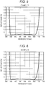
- Fig. 3 is a graph illustrating spectral reflectance characteristics of an antireflective film of a lens substrate in Comparative Example.
- Figs. 4 to 9 are graphs illustrating spectral reflectance characteristics of antireflective films of lens substrates in Examples 1 to 6. Note that the vertical axis indicates reflectance and the horizontal axis indicates wavelength of light in Figs. 3 to 9 .
- Fig. 3 illustrating the spectral reflectance characteristics of the lens substrate and the antireflective film in Comparative Example
- a maximum reflectance in a visible light wavelength range of 430 nm to 670 nm was 0.26%. It is found that Comparative Example has a relatively high maximum reflectance.
- Example 2 Conditions of the glass substrate 10 and the antireflective film 20 in Example 1 are illustrated in Table 2.
- Each layer of the antireflective film 20 was formed by a vacuum deposition method under heating at 300°C.
- the second layer 22 to the eighth layer 28 were formed by a vacuum deposition method using ion assist.
- a maximum reflectance in a visible light wavelength range of 430 nm to 670 nm was 0.04%. It is found that the maximum reflectance is suppressed to a very low value in Example 1 as compared with Comparative Example.
- Example 3 Conditions of the glass substrate 10 and the antireflective film 20 in Example 2 are illustrated in Table 3.
- Each layer of the antireflective film 20 was formed by a vacuum deposition method under heating at 300°C.
- the second layer 22 to the eighth layer 28 were formed by a vacuum deposition method using ion assist.
- a maximum reflectance in a visible light wavelength range of 430 nm to 670 nm was 0.04%. It is found that the maximum reflectance is suppressed to a very low value in Example 2 as compared with Comparative Example.
- Example 3 Conditions of the glass substrate 10 and the antireflective film 20 in Example 3 are illustrated in Table 4.
- Each layer of the antireflective film 20 was formed by a vacuum deposition method under heating at 300°C.
- the second layer 22 to the eighth layer 28 were formed by a vacuum deposition method using ion assist.
- a maximum reflectance in a visible light wavelength range of 430 nm to 670 nm was 0.04%. It is found that the maximum reflectance is suppressed to a very low value in Example 3 as compared with Comparative Example.
- Example 5 Conditions of the glass substrate 10 and the antireflective film 20 in Example 4 are illustrated in Table 5.
- Each layer of the antireflective film 20 was formed by a vacuum deposition method under heating at 300°C.
- the second layer 22 to the eighth layer 28 were formed by a vacuum deposition method using ion assist.
- Fig. 7 illustrating the spectral reflectance characteristics of the lens substrate 10 and the antireflective film 20 in Example 4, a maximum reflectance in a visible light wavelength range of 430 nm to 670 nm was 0.05%. It is found that the maximum reflectance is suppressed to a very low value in Example 4 as compared with Comparative Example.
- Example 5 Conditions of the glass substrate 10 and the antireflective film 20 in Example 5 are illustrated in Table 6.
- Each layer of the antireflective film 20 was formed by a vacuum deposition method under heating at 300°C.
- the second layer 22 to the eighth layer 28 were formed by a vacuum deposition method using ion assist.
- Fig. 8 illustrating the spectral reflectance characteristics of the lens substrate 10 and the antireflective film 20 in Example 5, a maximum reflectance in a visible light wavelength range of 430 nm to 670 nm was 0.06%. It is found that the maximum reflectance is suppressed to a very low value in Example 5 as compared with Comparative Example.
- Example 6 Conditions of the glass substrate 10 and the antireflective film 20 in Example 6 are illustrated in Table 7.
- Each layer of the antireflective film 20 was formed by a vacuum deposition method under heating at 300°C.
- the second layer 22 to the eighth layer 28 were formed by a vacuum deposition method using ion assist.
- Fig. 9 illustrating the spectral reflectance characteristics of the lens substrate 10 and the antireflective film 20 in Example 6, a maximum reflectance in a visible light wavelength range of 430 nm to 670 nm was 0.04%. It is found that the maximum reflectance is suppressed to a very low value in Example 6 as compared with Comparative Example.
- the antireflective film 20 it is possible to form the antireflective film 20 with a low reflectance and a small loss of light corresponding to the lens substrates 10 having various refractive indices. That is, it is possible to form the antireflective film 20 using a high refractive index material which has been relatively difficult to use conventionally, and it is possible to expand the degree of freedom of the configuration of the projection lens LN. As a result, it is possible to effectively suppress a decrease in the transmittance of the whole system of the projection lens LN, and it is possible to flexibly cope with an increase in the number of constituent lenses.
- each of the second layer 22, the fourth layer 24, the sixth layer 26, and the eighth layer 28 is formed of any one of Ta 2 O 5 , LaTiO 3 , a mixture of Ti 2 O 3 and ZrO 2 , and a mixture of ZrTiO 4 and ZrO 2 . Therefore, it is possible to form the antireflective film 20 with a small loss of light by a vacuum deposition method under a relatively high temperature environment of, for example, 300°C. There is a risk that practical strength may be lowered in a case where MgF 2 used in the first layer 21 is formed in a low temperature environment. Therefore, according to the configuration of the present embodiment, it is possible to increase the strength of the first layer 21.
- the antireflective film 20 desirably has a maximum reflectance of 0.2% or less in a wavelength range of 430 nm to 670 nm. This makes it possible to obtain the antireflective film 20 sufficient for application to a recent increase in the number of pixels of an image in the projection lens LN.
- the lens substrate 10 In addition, three or more types of glass materials among glass materials classified into five types satisfying the above formulas (9) to (13) regarding a refractive index n s are used as the lens substrate 10. Therefore, even with the projection lens LN obtained by combining the lens substrates 10 formed of various glass materials for thirty lenses, it is possible to form the antireflective film 20 with a low reflectance and a small loss of light. This makes it possible to further widen the degree of freedom of the configuration of the projection lens LN.
- the present invention can be used in a projection lens.
Landscapes
- Physics & Mathematics (AREA)
- General Physics & Mathematics (AREA)
- Optics & Photonics (AREA)
- Chemical & Material Sciences (AREA)
- Inorganic Chemistry (AREA)
- Engineering & Computer Science (AREA)
- Life Sciences & Earth Sciences (AREA)
- Chemical Kinetics & Catalysis (AREA)
- General Chemical & Material Sciences (AREA)
- Geochemistry & Mineralogy (AREA)
- Materials Engineering (AREA)
- Organic Chemistry (AREA)
- Surface Treatment Of Optical Elements (AREA)
- Lenses (AREA)
- Projection Apparatus (AREA)
Abstract
Description
- The present invention relates to a projection lens.
- In recent years, imaging performance required for a projection lens has been increased as the number of pixels of a projected image increases, and the number of constituent lenses tends to increase. Regarding this tendency, in a case of a conventional projection lens including 15 lenses each having four antireflective films formed on a surface of a lens substrate having, for example, a refractive index of 1.52, a light reflection loss of about 5% in the entire projection lens is generated on average in a visible light wavelength range. Furthermore, in a case of a projection lens including 30 lenses, there is a concern that a light reflection loss of about 10% is generated, and brightness of an image projected on a projection plane is largely reduced. Therefore, in order to suppress a decrease in the transmittance of the whole system of a projection lens in response to an increase in the number of constituent lenses, an antireflective film with a lower reflectance and a smaller loss of light is required for a lens substrate. An example of conventional technology related to solving this problem is disclosed in
Patent Literature 1. - In an antireflective film described in
Patent Literature 1, in order from a substrate side, a first layer is formed of a material having a refractive index lower than that of the substrate, second, fourth, sixth, and eighth layers are formed of a high refractive index material, third, fifth, seventh, and ninth layers are formed of a low refractive index material, and the optical film thickness of each of the layers is individually set to a predetermined value related to a design wavelength. This prevents reflection in a wide wavelength band from an ultraviolet region to an infrared region. - Patent Literature 1:
JP 2002-267803 A - However, according to the conventional technology described in
Patent Literature 1, even in an embodiment having the lowest maximum reflectance in a visible light wavelength range (for example, 420 nm to 690 nm), the maximum reflectance is about 0.5%, which is relatively high. As a result, it is a problem that a projection lens is insufficient for application to a recent increase in the number of pixels of an image. - The present invention has been achieved in view of the above points. An object of the present invention is to provide a projection lens capable of effectively suppressing a decrease in the transmittance of the whole system and capable of coping with an increase in the number of constituent lenses.
- In order to solve the above problems, the present invention provides a projection lens for projecting an image onto a projection plane, including: a lens substrate; and an antireflective film constituted by at least eight layers, formed on a surface of the lens substrate, characterized in that, in the antireflective film, in order from an air side, a first layer is formed of MgF2, each of a second layer, a fourth layer, a sixth layer, and an eighth layer has a refractive index of 2.0 to 2.3, each of a third layer, a fifth layer, and a seventh layer is formed of SiO2, and quarter wave optical thicknesses Q1 to Q8 for the first layer to the eighth layer with respect to a refractive index ns of the lens substrate at a design main wavelength of λ0 = 550 nm satisfy the following formulas (1) to (8).


- In addition, the projection lens having the above configuration is characterized in that each of the second layer, the fourth layer, the sixth layer, and the eighth layer is formed of any one of Ta2O5, LaTiO3, a mixture of Ti2O3 and ZrO2, and a mixture of ZrTiO4 and ZrO2.
- In addition, the projection lens having the above configuration is characterized in that the antireflective film has a maximum reflectance of 0.2% or less in a wavelength range of 430 nm to 670 nm.
- In addition, the projection lens having the above configuration is characterized in that three or more types of glass materials among glass materials classified into five types satisfying the following formulas (9) to (13) regarding a refractive index ns are used as the lens substrate.


- According to the present invention, it is possible to form an antireflective film with a low reflectance and a small loss of light corresponding to lens substrates having various refractive indices. That is, it is possible to form an antireflective film using a high refractive index material which has been relatively difficult to use conventionally, and it is possible to expand the degree of freedom of the configuration of a projection lens. As a result, it is possible to effectively suppress a decrease in the transmittance of the whole system of a projection lens, and it is possible to flexibly cope with an increase in the number of constituent lenses.
-
-
Fig. 1 is an optical configuration diagram of a projection lens according to an embodiment of the present invention. -
Fig. 2 is a layer configuration diagram of an antireflective film of a single lens of the projection lens according to the embodiment of the present invention. -
Fig. 3 is a graph illustrating spectral reflectance characteristics of an antireflective film of a lens substrate in Comparative Example with respect to the embodiment of the present invention. -
Fig. 4 is a graph illustrating spectral reflectance characteristics of an antireflective film of a lens substrate in Example 1 of the projection lens according to the embodiment of the present invention. -
Fig. 5 is a graph illustrating spectral reflectance characteristics of an antireflective film of a lens substrate in Example 2 of the projection lens according to the embodiment of the present invention. -
Fig. 6 is a graph illustrating spectral reflectance characteristics of an antireflective film of a lens substrate in Example 3 of the projection lens according to the embodiment of the present invention. -
Fig. 7 is a graph illustrating spectral reflectance characteristics of an antireflective film of a lens substrate in Example 4 of the projection lens according to the embodiment of the present invention. -
Fig. 8 is a graph illustrating spectral reflectance characteristics of an antireflective film of a lens substrate in Example 5 of the projection lens according to the embodiment of the present invention. -
Fig. 9 is a graph illustrating spectral reflectance characteristics of an antireflective film of a lens substrate in Example 6 of the projection lens according to the embodiment of the present invention. - Hereinafter, an example of an embodiment of the present invention will be described with reference to the drawings.
- First, the configuration of a projection lens according to the embodiment of the present invention will be described with reference to
Fig. 1. Fig. 1 is an optical configuration diagram of a projection lens, illustrating the lens cross-sectional shape, the lens arrangement, and the like of a projection lens LN with optical cross sections at each of a wide-angle end (W) and a telephoto end (T). The right side ofFig. 1 is a reduction side of the projection lens LN, and the left side ofFig. 1 is an enlargement side of the projection lens LN. Note that a prism PR (for example, a total internal reflection (TIR) prism or a color separation/synthesis prism) and a cover glass CG of an image display element are illustrated on the reduction side of the projection lens LN. - The projection lens LN is constituted by, for example, 30 lens components as a whole as illustrated in
Fig. 1 , and includes a first optical system LN1 and a second optical system LN2 in order from the enlargement side with an intermediate image plane IM1 interposed therebetween. The second optical system LN2 forms an intermediate image of an image displayed on an image display surface IM2 of an image display element on the intermediate image plane IM1. The first optical system LN1 enlarges and projects the intermediate image. Note that an aperture stop ST is located near the center of the second optical system LN2 in an optical axis direction. A relay lens is used in order to obtain both a wide field angle and excellent projection performance. Therefore, the number of constituent lenses is large. - Next, the detailed configuration of a single lens used for the projection lens LN will be described with reference to
Fig. 2. Fig. 2 is a layer configuration diagram of an antireflective film of a single lens. - A
lens 1 used for the projection lens LN includes alens substrate 10 and anantireflective film 20 illustrated inFig. 2 . Thelens substrate 10 is constituted by a transparent substrate formed of, for example, glass (glass material). On a surface of thelens substrate 10, theantireflective film 20 constituted by eight layers is formed. - The
antireflective film 20 includes, in order from an air side, afirst layer 21, asecond layer 22, athird layer 23, afourth layer 24, afifth layer 25, asixth layer 26, aseventh layer 27, and aneighth layer 28. Thefirst layer 21 is formed of MgF2. Each of thesecond layer 22, thefourth layer 24, thesixth layer 26, and theeighth layer 28 is formed of a so-called high refractive index material having a refractive index of 2.0 to 2.3. Each of thethird layer 23, thefifth layer 25, and theseventh layer 27 is formed of SiO2. - The quarter wave optical thicknesses (QWOT) Q1 to Q8 of the
first layer 21 to theeighth layer 28 with respect to a refractive index ns of thelens substrate 10 at a design main wavelength of λ0 = 550 nm satisfy the following formulas (1) to (8).


- Each of the layers of the
antireflective film 20 is formed by a vacuum deposition method under heating, for example, at 300°C. Particularly, thesecond layer 22 to theeighth layer 28 are formed by a vacuum deposition method using ion assist. Ion-assisted vapor deposition is desirably used in order to reduce a change in film density of theantireflective film 20 and the roughness of a film surface due to variation of the degree of vacuum and the like in the vacuum deposition method. This makes it possible to suppress occurrence of color unevenness and deterioration of characteristic reproducibility caused by a change in film density, that is, a change in refractive index of a film. When ion-assisted vapor deposition is used for forming theantireflective film 20, it is possible to use a high refractive index material which has been relatively difficult to use conventionally for the layers constituting theantireflective film 20. - According to the above configuration, the
antireflective film 20 has a maximum reflectance of 0.2% or less in a wavelength range of 430 nm to 670 nm. - Note that each of the
second layer 22, thefourth layer 24, thesixth layer 26, and theeighth layer 28 in theantireflective film 20 is preferably formed of any one of Ta2O5, LaTiO3, a mixture of Ti2O3 and ZrO2, and a mixture of ZrTiO4 and ZrO2. - In each of the 30 lenses of the projection lens LN, three or more types of glass materials having different refractive indexes ns are used as the
lens substrate 10. Specifically, three or more types of glass materials among glass materials classified into five types satisfying the following formulas (9) to (13) regarding a refractive index ns are used as thelens substrate 10.


- Subsequently, regarding the present embodiment, evaluation of light reflectance of a lens substrate and an antireflective film in each of Examples and a lens substrate and an antireflective film in Comparative Example will be described with reference to
Figs. 3 to 9 .Fig. 3 is a graph illustrating spectral reflectance characteristics of an antireflective film of a lens substrate in Comparative Example.Figs. 4 to 9 are graphs illustrating spectral reflectance characteristics of antireflective films of lens substrates in Examples 1 to 6. Note that the vertical axis indicates reflectance and the horizontal axis indicates wavelength of light inFigs. 3 to 9 . - Conditions of a glass substrate and an antireflective film in Comparative Example are illustrated in Table 1. In Comparative Example, a general antireflective film constituted by four layers was formed on a surface of a glass lens substrate having a refractive index ns = 1.52 at a design main wavelength of λ0 = 550 nm. Each layer of the antireflective film was formed by a vacuum deposition method under heating at 300°C.
[Table 1] Comparative Example Design main wavelength λ0 = 550 [nm] Material for layer QWOT First layer MgF2 0.93 Second layer LaTiO3 1.86 Third layer AL2O3 1.09 Fourth layer MgF2 0.41 Lens substrate Refractive index ns: 1.52 - According to
Fig. 3 illustrating the spectral reflectance characteristics of the lens substrate and the antireflective film in Comparative Example, a maximum reflectance in a visible light wavelength range of 430 nm to 670 nm was 0.26%. It is found that Comparative Example has a relatively high maximum reflectance. - Conditions of the
glass substrate 10 and theantireflective film 20 in Example 1 are illustrated in Table 2. In Example 1, theantireflective film 20 constituted by eight layers was formed on a surface of theglass lens substrate 10 having a refractive index ns = 1.52 at a design main wavelength of λ0 = 550 nm. The quarter wave optical thicknesses (QWOT) Q1 to Q8 of thefirst layer 21 to theeighth layer 28 with respect to a refractive index ns = 1.52 of thelens substrate 10 at a design main wavelength of λ0 = 550 nm satisfy the following formulas (1) to (8). Each layer of theantireflective film 20 was formed by a vacuum deposition method under heating at 300°C. Particularly, thesecond layer 22 to theeighth layer 28 were formed by a vacuum deposition method using ion assist.[Table 2] Example 1 Design main wavelength λ0 = 550 [nm] Material for layer QWOT First layer MgF2 Q1 0.94 Second layer Ta2O5 Q2 1.89 Third layer SiO2 Q3 2.01 Fourth layer Ta2O5 Q4 0.67 Fifth layer SiO2 Q5 0.19 Sixth layer Ta2O5 Q6 0.85 Seventh layer SiO2 Q7 0.43 Eighth layer Ta2O5 Q8 0.22 Lens substrate Refractive index ns: 1.52 - According to
Fig. 4 illustrating the spectral reflectance characteristics of thelens substrate 10 and theantireflective film 20 in Example 1, a maximum reflectance in a visible light wavelength range of 430 nm to 670 nm was 0.04%. It is found that the maximum reflectance is suppressed to a very low value in Example 1 as compared with Comparative Example. - Conditions of the
glass substrate 10 and theantireflective film 20 in Example 2 are illustrated in Table 3. In Example 2, theantireflective film 20 constituted by eight layers was formed on a surface of theglass lens substrate 10 having a refractive index ns = 1.62 at a design main wavelength of λ0 = 550 nm. The quarter wave optical thicknesses (QWOT) Q1 to Q8 of thefirst layer 21 to theeighth layer 28 with respect to a refractive index ns = 1.62 of thelens substrate 10 at a design main wavelength of λ0 = 550 nm satisfy the following formulas (1) to (8). Each layer of theantireflective film 20 was formed by a vacuum deposition method under heating at 300°C. Particularly, thesecond layer 22 to theeighth layer 28 were formed by a vacuum deposition method using ion assist.[Table 3] Example 2 Design main wavelength λ0 = 550 [nm] Material for layer QWOT First layer MgF2 Q1 0.95 Second layer Ta2O5 Q2 1.89 Third layer SiO2 Q3 1.99 Fourth layer Ta2O5 Q4 0.66 Fifth layer SiO2 Q5 0.13 Sixth layer Ta2O5 Q6 1.07 Seventh layer SiO2 Q7 0.33 Eighth layer Ta2O5 Q8 0.26 Lens substrate Refractive index ns: 1.62 - According to
Fig. 5 illustrating the spectral reflectance characteristics of thelens substrate 10 and theantireflective film 20 in Example 2, a maximum reflectance in a visible light wavelength range of 430 nm to 670 nm was 0.04%. It is found that the maximum reflectance is suppressed to a very low value in Example 2 as compared with Comparative Example. - Conditions of the
glass substrate 10 and theantireflective film 20 in Example 3 are illustrated in Table 4. In Example 3, theantireflective film 20 constituted by eight layers was formed on a surface of theglass lens substrate 10 having a refractive index ns = 1.72 at a design main wavelength of λ0 = 550 nm. The quarter wave optical thicknesses (QWOT) Q1 to Q8 of thefirst layer 21 to theeighth layer 28 with respect to a refractive index ns = 1.72 of thelens substrate 10 at a design main wavelength of λ0 = 550 nm satisfy the following formulas (1) to (8). Each layer of theantireflective film 20 was formed by a vacuum deposition method under heating at 300°C. Particularly, thesecond layer 22 to theeighth layer 28 were formed by a vacuum deposition method using ion assist.[Table 4] Example 3 Design main wavelength λ0 = 550 [nm] Material for layer QWOT First layer MgF2 Q1 0.95 Second layer Ta2O5 Q2 1.90 Third layer SiO2 Q3 1.99 Fourth layer Ta2O5 Q4 0.63 Fifth layer SiO2 Q5 0.13 Sixth layer Ta2O5 Q6 1.14 Seventh layer SiO2 Q7 0.27 Eighth layer Ta2O5 Q8 0.29 Lens substrate Refractive index ns: 1.72 - According to
Fig. 6 illustrating the spectral reflectance characteristics of thelens substrate 10 and theantireflective film 20 in Example 3, a maximum reflectance in a visible light wavelength range of 430 nm to 670 nm was 0.04%. It is found that the maximum reflectance is suppressed to a very low value in Example 3 as compared with Comparative Example. - Conditions of the
glass substrate 10 and theantireflective film 20 in Example 4 are illustrated in Table 5. In Example 4, theantireflective film 20 constituted by eight layers was formed on a surface of theglass lens substrate 10 having a refractive index ns = 1.82 at a design main wavelength of λ0 = 550 nm. The quarter wave optical thicknesses (QWOT) Q1 to Q8 of thefirst layer 21 to theeighth layer 28 with respect to a refractive index ns = 1.82 of thelens substrate 10 at a design main wavelength of λ0 = 550 nm satisfy the following formulas (1) to (8). Each layer of theantireflective film 20 was formed by a vacuum deposition method under heating at 300°C. Particularly, thesecond layer 22 to theeighth layer 28 were formed by a vacuum deposition method using ion assist.[Table 5] Example 4 Design main wavelength λ0 = 550 [nm] Material for layer QWOT First layer MgF2 Q1 0.95 Second layer Ta2O5 Q2 1.90 Third layer SiO2 Q3 1.99 Fourth layer Ta2O5 Q4 0.60 Fifth layer SiO2 Q5 0.13 Sixth layer Ta2O5 Q6 1.23 Seventh layer SiO2 Q7 0.22 Eighth layer Ta2O5 Q8 0.32 Lens substrate Refractive index ns: 1.82 - According to
Fig. 7 illustrating the spectral reflectance characteristics of thelens substrate 10 and theantireflective film 20 in Example 4, a maximum reflectance in a visible light wavelength range of 430 nm to 670 nm was 0.05%. It is found that the maximum reflectance is suppressed to a very low value in Example 4 as compared with Comparative Example. - Conditions of the
glass substrate 10 and theantireflective film 20 in Example 5 are illustrated in Table 6. In Example 5, theantireflective film 20 constituted by eight layers was formed on a surface of theglass lens substrate 10 having a refractive index ns = 1.92 at a design main wavelength of λ0 = 550 nm. The quarter wave optical thicknesses (QWOT) Q1 to Q8 of thefirst layer 21 to theeighth layer 28 with respect to a refractive index ns = 1.92 of thelens substrate 10 at a design main wavelength of λ0 = 550 nm satisfy the following formulas (1) to (8). Each layer of theantireflective film 20 was formed by a vacuum deposition method under heating at 300°C. Particularly, thesecond layer 22 to theeighth layer 28 were formed by a vacuum deposition method using ion assist.[Table 6] Example 5 Design main wavelength λ0 = 550 [nm] Material for layer QWOT First layer MgF2 Q1 0.95 Second layer Ta2O5 Q2 1.90 Third layer SiO2 Q3 1.99 Fourth layer Ta2O5 Q4 0.57 Fifth layer SiO2 Q5 0.13 Sixth layer Ta2O5 Q6 1.32 Seventh layer SiO2 Q7 0.17 Eighth layer Ta2O5 Q8 0.34 Lens substrate Refractive index ns: 1.92 - According to
Fig. 8 illustrating the spectral reflectance characteristics of thelens substrate 10 and theantireflective film 20 in Example 5, a maximum reflectance in a visible light wavelength range of 430 nm to 670 nm was 0.06%. It is found that the maximum reflectance is suppressed to a very low value in Example 5 as compared with Comparative Example. - Conditions of the
glass substrate 10 and theantireflective film 20 in Example 6 are illustrated in Table 7. In Example 6, theantireflective film 20 constituted by nine layers was formed on a surface of theglass lens substrate 10 having a refractive index ns = 1.62 at a design main wavelength of λ0 = 550 nm. The quarter wave optical thicknesses (QWOT) Q1 to Q8 of thefirst layer 21 to theeighth layer 28 with respect to a refractive index ns = 1.62 of thelens substrate 10 at a design main wavelength of λ0 = 550 nm satisfy the following formulas (1) to (8). Each layer of theantireflective film 20 was formed by a vacuum deposition method under heating at 300°C. Particularly, thesecond layer 22 to theeighth layer 28 were formed by a vacuum deposition method using ion assist.[Table 7] Example 6 Design main wavelength λ0 = 550 [nm] Material for layer QWOT First layer MgF2 Q1 0.94 Second layer Ta2O5 Q2 1.89 Third layer SiO2 Q3 1.98 Fourth layer Ta2O5 Q4 0.67 Fifth layer SiO2 Q5 0.13 Sixth layer Ta2O5 Q6 1.07 Seventh layer SiO2 Q7 0.33 Eighth layer Ta2O5 Q8 0.26 Ninth layer Al2O3 Q9 0.14 Lens substrate Refractive index ns: 1.62 - According to
Fig. 9 illustrating the spectral reflectance characteristics of thelens substrate 10 and theantireflective film 20 in Example 6, a maximum reflectance in a visible light wavelength range of 430 nm to 670 nm was 0.04%. It is found that the maximum reflectance is suppressed to a very low value in Example 6 as compared with Comparative Example. - In this way, according to the configuration of the embodiment, it is possible to form the
antireflective film 20 with a low reflectance and a small loss of light corresponding to thelens substrates 10 having various refractive indices. That is, it is possible to form theantireflective film 20 using a high refractive index material which has been relatively difficult to use conventionally, and it is possible to expand the degree of freedom of the configuration of the projection lens LN. As a result, it is possible to effectively suppress a decrease in the transmittance of the whole system of the projection lens LN, and it is possible to flexibly cope with an increase in the number of constituent lenses. - Furthermore, in the
antireflective film 20, each of thesecond layer 22, thefourth layer 24, thesixth layer 26, and theeighth layer 28 is formed of any one of Ta2O5, LaTiO3, a mixture of Ti2O3 and ZrO2, and a mixture of ZrTiO4 and ZrO2. Therefore, it is possible to form theantireflective film 20 with a small loss of light by a vacuum deposition method under a relatively high temperature environment of, for example, 300°C. There is a risk that practical strength may be lowered in a case where MgF2 used in thefirst layer 21 is formed in a low temperature environment. Therefore, according to the configuration of the present embodiment, it is possible to increase the strength of thefirst layer 21. - The
antireflective film 20 desirably has a maximum reflectance of 0.2% or less in a wavelength range of 430 nm to 670 nm. This makes it possible to obtain theantireflective film 20 sufficient for application to a recent increase in the number of pixels of an image in the projection lens LN. - In addition, three or more types of glass materials among glass materials classified into five types satisfying the above formulas (9) to (13) regarding a refractive index ns are used as the
lens substrate 10. Therefore, even with the projection lens LN obtained by combining thelens substrates 10 formed of various glass materials for thirty lenses, it is possible to form theantireflective film 20 with a low reflectance and a small loss of light. This makes it possible to further widen the degree of freedom of the configuration of the projection lens LN. - The embodiment of the present invention has been described above. However, the scope of the present invention is not limited to the embodiment, and the present invention can be carried out by making various modifications to the embodiment without departing from the gist of the invention.
- The present invention can be used in a projection lens.
-
- 1
- Glass
- 10
- Glass substrate
- 20
- Antireflective film
- 21
- First layer
- 22
- Second layer
- 23
- Third layer
- 24
- Fourth layer
- 25
- Fifth layer
- 26
- Sixth layer
- 27
- Seventh layer
- 28
- Eighth layer
- LN
- Projection lens
Claims (4)
- A projection lens for projecting an image onto a projection plane, comprising:a lens substrate; andan antireflective film constituted by at least eight layers, formed on a surface of the lens substrate, whereinin the antireflective film, in order from an air side, a first layer is formed of MgF2, each of a second layer, a fourth layer, a sixth layer, and an eighth layer has a refractive index of 2.0 to 2.3, each of a third layer, a fifth layer, and a seventh layer is formed of SiO2, and quarter wave optical thicknesses Q1 to Q8 for the first layer to the eighth layer with respect to a refractive index ns of the lens substrate at a design main wavelength of λ0 = 550 nm satisfy the following formulas (1) to (8).


- The projection lens according to claim 1, wherein each of the second layer, the fourth layer, the sixth layer, and the eighth layer is formed of any one of Ta2O5, LaTiO3, a mixture of Ti2O3 and ZrO2, and a mixture of ZrTiO4 and ZrO2.
- The projection lens according to claim 1 or 2, wherein the antireflective film has a maximum reflectance of 0.2% or less in a wavelength range of 430 nm to 670 nm.
- The projection lens according to any one of claims 1 to 3, wherein three or more types of glass materials among glass materials classified into five types satisfying the following formulas (9) to (13) regarding a refractive index ns are used as the lens substrate.


Applications Claiming Priority (2)
| Application Number | Priority Date | Filing Date | Title |
|---|---|---|---|
| JP2016105391 | 2016-05-26 | ||
| PCT/JP2017/018922 WO2017204127A1 (en) | 2016-05-26 | 2017-05-19 | Projection lens |
Publications (3)
| Publication Number | Publication Date |
|---|---|
| EP3467549A1 true EP3467549A1 (en) | 2019-04-10 |
| EP3467549A4 EP3467549A4 (en) | 2019-05-22 |
| EP3467549B1 EP3467549B1 (en) | 2020-07-08 |
Family
ID=60412358
Family Applications (1)
| Application Number | Title | Priority Date | Filing Date |
|---|---|---|---|
| EP17802719.9A Active EP3467549B1 (en) | 2016-05-26 | 2017-05-19 | Projection lens |
Country Status (5)
| Country | Link |
|---|---|
| US (1) | US10942294B2 (en) |
| EP (1) | EP3467549B1 (en) |
| JP (1) | JP6795031B2 (en) |
| CN (1) | CN109154679B (en) |
| WO (1) | WO2017204127A1 (en) |
Families Citing this family (3)
| Publication number | Priority date | Publication date | Assignee | Title |
|---|---|---|---|---|
| CN114846362B (en) * | 2019-12-25 | 2023-12-29 | 柯尼卡美能达株式会社 | Method for manufacturing optical lens with antireflection film |
| JP7347203B2 (en) * | 2019-12-25 | 2023-09-20 | コニカミノルタ株式会社 | Optical lenses with anti-reflection coating, projection lenses and projection lens optical systems |
| JP7306369B2 (en) * | 2020-12-24 | 2023-07-11 | セイコーエプソン株式会社 | Projection optical system and projector |
Family Cites Families (8)
| Publication number | Priority date | Publication date | Assignee | Title |
|---|---|---|---|---|
| JP4780845B2 (en) | 2001-03-12 | 2011-09-28 | オリンパス株式会社 | Antireflection film and optical component |
| US7075714B2 (en) * | 2002-02-26 | 2006-07-11 | Olympus Corporation | Anti-reflection film and microscope having optical element with the same anti-reflection film applied thereto |
| JP4822786B2 (en) | 2005-09-29 | 2011-11-24 | Hoya株式会社 | Antireflection film and optical component having the same |
| JP4958536B2 (en) * | 2006-01-12 | 2012-06-20 | 富士フイルム株式会社 | Anti-reflection coating |
| JP5197274B2 (en) * | 2008-09-26 | 2013-05-15 | 日東光学株式会社 | Optical member manufacturing method and optical member |
| US9201172B2 (en) * | 2012-09-14 | 2015-12-01 | Ricoh Imaging Company, Ltd. | Anti-reflection coating, optical member having it, and optical equipment comprising such optical member |
| JP6241102B2 (en) * | 2013-07-19 | 2017-12-06 | リコーイメージング株式会社 | Antireflection film, optical member using the same, and optical instrument |
| JP6108871B2 (en) * | 2013-02-25 | 2017-04-05 | オリンパス株式会社 | Antireflection film, optical system, and optical apparatus |
-
2017
- 2017-05-19 EP EP17802719.9A patent/EP3467549B1/en active Active
- 2017-05-19 US US16/303,591 patent/US10942294B2/en active Active
- 2017-05-19 CN CN201780031679.2A patent/CN109154679B/en active Active
- 2017-05-19 WO PCT/JP2017/018922 patent/WO2017204127A1/en unknown
- 2017-05-19 JP JP2018519513A patent/JP6795031B2/en active Active
Also Published As
| Publication number | Publication date |
|---|---|
| WO2017204127A1 (en) | 2017-11-30 |
| EP3467549A4 (en) | 2019-05-22 |
| JPWO2017204127A1 (en) | 2019-03-28 |
| JP6795031B2 (en) | 2020-12-02 |
| US20200319376A1 (en) | 2020-10-08 |
| EP3467549B1 (en) | 2020-07-08 |
| CN109154679A (en) | 2019-01-04 |
| US10942294B2 (en) | 2021-03-09 |
| CN109154679B (en) | 2021-05-14 |
Similar Documents
| Publication | Publication Date | Title |
|---|---|---|
| EP2708922B1 (en) | Anti-reflection coating, optical member having it, and optical equipment comprising such optical member | |
| JP4958536B2 (en) | Anti-reflection coating | |
| JP5662982B2 (en) | Antireflection film and optical element | |
| EP1972966A2 (en) | Antireflection film, optical element and optical system | |
| JP6051710B2 (en) | Antireflection film, optical member using the same, and optical instrument | |
| EP3467549B1 (en) | Projection lens | |
| JP4190773B2 (en) | Antireflection film, optical lens and optical lens unit | |
| US20200319387A1 (en) | Optical filter and imaging apparatus | |
| US20140247481A1 (en) | Optical component for the ir range with stress-compensated coating | |
| JP6241102B2 (en) | Antireflection film, optical member using the same, and optical instrument | |
| JP2007333806A (en) | Antireflection film and optical member | |
| US11846754B2 (en) | Optical lens with antireflective film, projection lens, and projection lens optical system | |
| US20200209434A1 (en) | Optical element and projection lens | |
| KR20130047634A (en) | Antireflective film and optical element | |
| JP2002267801A (en) | Antireflection film and optical member which uses the same | |
| JP5292318B2 (en) | Antireflection film and optical member having the same | |
| TW202326182A (en) | Optical lens assembly, imaging apparatus and electronic device | |
| US20120200927A1 (en) | Optical element having anti-reflection film | |
| JP6361095B2 (en) | Antireflection film, optical member using the same, and optical instrument | |
| JP7332359B2 (en) | Anti-reflective coating | |
| CN106556882B (en) | Optical article and spectacle lens | |
| JP3002002B2 (en) | Bandpass filter | |
| JP2017040946A (en) | Antireflection film, optical member using the same, and optical apparatus | |
| JP2018105937A (en) | Roof prism |
Legal Events
| Date | Code | Title | Description |
|---|---|---|---|
| STAA | Information on the status of an ep patent application or granted ep patent |
Free format text: STATUS: THE INTERNATIONAL PUBLICATION HAS BEEN MADE |
|
| PUAI | Public reference made under article 153(3) epc to a published international application that has entered the european phase |
Free format text: ORIGINAL CODE: 0009012 |
|
| STAA | Information on the status of an ep patent application or granted ep patent |
Free format text: STATUS: REQUEST FOR EXAMINATION WAS MADE |
|
| 17P | Request for examination filed |
Effective date: 20181121 |
|
| AK | Designated contracting states |
Kind code of ref document: A1 Designated state(s): AL AT BE BG CH CY CZ DE DK EE ES FI FR GB GR HR HU IE IS IT LI LT LU LV MC MK MT NL NO PL PT RO RS SE SI SK SM TR |
|
| AX | Request for extension of the european patent |
Extension state: BA ME |
|
| A4 | Supplementary search report drawn up and despatched |
Effective date: 20190423 |
|
| RIC1 | Information provided on ipc code assigned before grant |
Ipc: G02B 13/16 20060101ALI20190415BHEP Ipc: G03B 21/14 20060101ALI20190415BHEP Ipc: G02B 1/115 20150101AFI20190415BHEP |
|
| DAV | Request for validation of the european patent (deleted) | ||
| DAX | Request for extension of the european patent (deleted) | ||
| GRAP | Despatch of communication of intention to grant a patent |
Free format text: ORIGINAL CODE: EPIDOSNIGR1 |
|
| STAA | Information on the status of an ep patent application or granted ep patent |
Free format text: STATUS: GRANT OF PATENT IS INTENDED |
|
| INTG | Intention to grant announced |
Effective date: 20200214 |
|
| RIN1 | Information on inventor provided before grant (corrected) |
Inventor name: TAKAHARA, KOJI Inventor name: NAKANO, YOSHIHIRO Inventor name: TERAMOTO, MIYUKI |
|
| GRAS | Grant fee paid |
Free format text: ORIGINAL CODE: EPIDOSNIGR3 |
|
| GRAA | (expected) grant |
Free format text: ORIGINAL CODE: 0009210 |
|
| STAA | Information on the status of an ep patent application or granted ep patent |
Free format text: STATUS: THE PATENT HAS BEEN GRANTED |
|
| AK | Designated contracting states |
Kind code of ref document: B1 Designated state(s): AL AT BE BG CH CY CZ DE DK EE ES FI FR GB GR HR HU IE IS IT LI LT LU LV MC MK MT NL NO PL PT RO RS SE SI SK SM TR |
|
| REG | Reference to a national code |
Ref country code: CH Ref legal event code: EP Ref country code: AT Ref legal event code: REF Ref document number: 1289061 Country of ref document: AT Kind code of ref document: T Effective date: 20200715 |
|
| REG | Reference to a national code |
Ref country code: DE Ref legal event code: R096 Ref document number: 602017019570 Country of ref document: DE |
|
| REG | Reference to a national code |
Ref country code: IE Ref legal event code: FG4D |
|
| REG | Reference to a national code |
Ref country code: LT Ref legal event code: MG4D |
|
| REG | Reference to a national code |
Ref country code: NL Ref legal event code: MP Effective date: 20200708 |
|
| PG25 | Lapsed in a contracting state [announced via postgrant information from national office to epo] |
Ref country code: FI Free format text: LAPSE BECAUSE OF FAILURE TO SUBMIT A TRANSLATION OF THE DESCRIPTION OR TO PAY THE FEE WITHIN THE PRESCRIBED TIME-LIMIT Effective date: 20200708 Ref country code: NO Free format text: LAPSE BECAUSE OF FAILURE TO SUBMIT A TRANSLATION OF THE DESCRIPTION OR TO PAY THE FEE WITHIN THE PRESCRIBED TIME-LIMIT Effective date: 20201008 Ref country code: SE Free format text: LAPSE BECAUSE OF FAILURE TO SUBMIT A TRANSLATION OF THE DESCRIPTION OR TO PAY THE FEE WITHIN THE PRESCRIBED TIME-LIMIT Effective date: 20200708 Ref country code: GR Free format text: LAPSE BECAUSE OF FAILURE TO SUBMIT A TRANSLATION OF THE DESCRIPTION OR TO PAY THE FEE WITHIN THE PRESCRIBED TIME-LIMIT Effective date: 20201009 Ref country code: ES Free format text: LAPSE BECAUSE OF FAILURE TO SUBMIT A TRANSLATION OF THE DESCRIPTION OR TO PAY THE FEE WITHIN THE PRESCRIBED TIME-LIMIT Effective date: 20200708 Ref country code: PT Free format text: LAPSE BECAUSE OF FAILURE TO SUBMIT A TRANSLATION OF THE DESCRIPTION OR TO PAY THE FEE WITHIN THE PRESCRIBED TIME-LIMIT Effective date: 20201109 Ref country code: BG Free format text: LAPSE BECAUSE OF FAILURE TO SUBMIT A TRANSLATION OF THE DESCRIPTION OR TO PAY THE FEE WITHIN THE PRESCRIBED TIME-LIMIT Effective date: 20201008 Ref country code: LT Free format text: LAPSE BECAUSE OF FAILURE TO SUBMIT A TRANSLATION OF THE DESCRIPTION OR TO PAY THE FEE WITHIN THE PRESCRIBED TIME-LIMIT Effective date: 20200708 Ref country code: HR Free format text: LAPSE BECAUSE OF FAILURE TO SUBMIT A TRANSLATION OF THE DESCRIPTION OR TO PAY THE FEE WITHIN THE PRESCRIBED TIME-LIMIT Effective date: 20200708 |
|
| PG25 | Lapsed in a contracting state [announced via postgrant information from national office to epo] |
Ref country code: PL Free format text: LAPSE BECAUSE OF FAILURE TO SUBMIT A TRANSLATION OF THE DESCRIPTION OR TO PAY THE FEE WITHIN THE PRESCRIBED TIME-LIMIT Effective date: 20200708 Ref country code: LV Free format text: LAPSE BECAUSE OF FAILURE TO SUBMIT A TRANSLATION OF THE DESCRIPTION OR TO PAY THE FEE WITHIN THE PRESCRIBED TIME-LIMIT Effective date: 20200708 Ref country code: RS Free format text: LAPSE BECAUSE OF FAILURE TO SUBMIT A TRANSLATION OF THE DESCRIPTION OR TO PAY THE FEE WITHIN THE PRESCRIBED TIME-LIMIT Effective date: 20200708 Ref country code: IS Free format text: LAPSE BECAUSE OF FAILURE TO SUBMIT A TRANSLATION OF THE DESCRIPTION OR TO PAY THE FEE WITHIN THE PRESCRIBED TIME-LIMIT Effective date: 20201108 |
|
| PG25 | Lapsed in a contracting state [announced via postgrant information from national office to epo] |
Ref country code: NL Free format text: LAPSE BECAUSE OF FAILURE TO SUBMIT A TRANSLATION OF THE DESCRIPTION OR TO PAY THE FEE WITHIN THE PRESCRIBED TIME-LIMIT Effective date: 20200708 |
|
| REG | Reference to a national code |
Ref country code: DE Ref legal event code: R097 Ref document number: 602017019570 Country of ref document: DE |
|
| PG25 | Lapsed in a contracting state [announced via postgrant information from national office to epo] |
Ref country code: IT Free format text: LAPSE BECAUSE OF FAILURE TO SUBMIT A TRANSLATION OF THE DESCRIPTION OR TO PAY THE FEE WITHIN THE PRESCRIBED TIME-LIMIT Effective date: 20200708 Ref country code: SM Free format text: LAPSE BECAUSE OF FAILURE TO SUBMIT A TRANSLATION OF THE DESCRIPTION OR TO PAY THE FEE WITHIN THE PRESCRIBED TIME-LIMIT Effective date: 20200708 Ref country code: DK Free format text: LAPSE BECAUSE OF FAILURE TO SUBMIT A TRANSLATION OF THE DESCRIPTION OR TO PAY THE FEE WITHIN THE PRESCRIBED TIME-LIMIT Effective date: 20200708 Ref country code: CZ Free format text: LAPSE BECAUSE OF FAILURE TO SUBMIT A TRANSLATION OF THE DESCRIPTION OR TO PAY THE FEE WITHIN THE PRESCRIBED TIME-LIMIT Effective date: 20200708 Ref country code: RO Free format text: LAPSE BECAUSE OF FAILURE TO SUBMIT A TRANSLATION OF THE DESCRIPTION OR TO PAY THE FEE WITHIN THE PRESCRIBED TIME-LIMIT Effective date: 20200708 Ref country code: EE Free format text: LAPSE BECAUSE OF FAILURE TO SUBMIT A TRANSLATION OF THE DESCRIPTION OR TO PAY THE FEE WITHIN THE PRESCRIBED TIME-LIMIT Effective date: 20200708 |
|
| PLBE | No opposition filed within time limit |
Free format text: ORIGINAL CODE: 0009261 |
|
| STAA | Information on the status of an ep patent application or granted ep patent |
Free format text: STATUS: NO OPPOSITION FILED WITHIN TIME LIMIT |
|
| PG25 | Lapsed in a contracting state [announced via postgrant information from national office to epo] |
Ref country code: AL Free format text: LAPSE BECAUSE OF FAILURE TO SUBMIT A TRANSLATION OF THE DESCRIPTION OR TO PAY THE FEE WITHIN THE PRESCRIBED TIME-LIMIT Effective date: 20200708 |
|
| REG | Reference to a national code |
Ref country code: AT Ref legal event code: UEP Ref document number: 1289061 Country of ref document: AT Kind code of ref document: T Effective date: 20200708 |
|
| 26N | No opposition filed |
Effective date: 20210409 |
|
| PG25 | Lapsed in a contracting state [announced via postgrant information from national office to epo] |
Ref country code: SK Free format text: LAPSE BECAUSE OF FAILURE TO SUBMIT A TRANSLATION OF THE DESCRIPTION OR TO PAY THE FEE WITHIN THE PRESCRIBED TIME-LIMIT Effective date: 20200708 |
|
| PG25 | Lapsed in a contracting state [announced via postgrant information from national office to epo] |
Ref country code: SI Free format text: LAPSE BECAUSE OF FAILURE TO SUBMIT A TRANSLATION OF THE DESCRIPTION OR TO PAY THE FEE WITHIN THE PRESCRIBED TIME-LIMIT Effective date: 20200708 |
|
| REG | Reference to a national code |
Ref country code: CH Ref legal event code: PL |
|
| PG25 | Lapsed in a contracting state [announced via postgrant information from national office to epo] |
Ref country code: CH Free format text: LAPSE BECAUSE OF NON-PAYMENT OF DUE FEES Effective date: 20210531 Ref country code: LI Free format text: LAPSE BECAUSE OF NON-PAYMENT OF DUE FEES Effective date: 20210531 Ref country code: LU Free format text: LAPSE BECAUSE OF NON-PAYMENT OF DUE FEES Effective date: 20210519 Ref country code: MC Free format text: LAPSE BECAUSE OF FAILURE TO SUBMIT A TRANSLATION OF THE DESCRIPTION OR TO PAY THE FEE WITHIN THE PRESCRIBED TIME-LIMIT Effective date: 20200708 |
|
| REG | Reference to a national code |
Ref country code: BE Ref legal event code: MM Effective date: 20210531 |
|
| PG25 | Lapsed in a contracting state [announced via postgrant information from national office to epo] |
Ref country code: IE Free format text: LAPSE BECAUSE OF NON-PAYMENT OF DUE FEES Effective date: 20210519 |
|
| PG25 | Lapsed in a contracting state [announced via postgrant information from national office to epo] |
Ref country code: BE Free format text: LAPSE BECAUSE OF NON-PAYMENT OF DUE FEES Effective date: 20210531 |
|
| PGFP | Annual fee paid to national office [announced via postgrant information from national office to epo] |
Ref country code: FR Payment date: 20230309 Year of fee payment: 7 |
|
| PGFP | Annual fee paid to national office [announced via postgrant information from national office to epo] |
Ref country code: GB Payment date: 20230330 Year of fee payment: 7 |
|
| P01 | Opt-out of the competence of the unified patent court (upc) registered |
Effective date: 20230510 |
|
| PG25 | Lapsed in a contracting state [announced via postgrant information from national office to epo] |
Ref country code: CY Free format text: LAPSE BECAUSE OF FAILURE TO SUBMIT A TRANSLATION OF THE DESCRIPTION OR TO PAY THE FEE WITHIN THE PRESCRIBED TIME-LIMIT Effective date: 20200708 |
|
| PG25 | Lapsed in a contracting state [announced via postgrant information from national office to epo] |
Ref country code: HU Free format text: LAPSE BECAUSE OF FAILURE TO SUBMIT A TRANSLATION OF THE DESCRIPTION OR TO PAY THE FEE WITHIN THE PRESCRIBED TIME-LIMIT; INVALID AB INITIO Effective date: 20170519 |
|
| PGFP | Annual fee paid to national office [announced via postgrant information from national office to epo] |
Ref country code: DE Payment date: 20230321 Year of fee payment: 7 |
|
| PGFP | Annual fee paid to national office [announced via postgrant information from national office to epo] |
Ref country code: AT Payment date: 20230425 Year of fee payment: 7 |
|
| PG25 | Lapsed in a contracting state [announced via postgrant information from national office to epo] |
Ref country code: MK Free format text: LAPSE BECAUSE OF FAILURE TO SUBMIT A TRANSLATION OF THE DESCRIPTION OR TO PAY THE FEE WITHIN THE PRESCRIBED TIME-LIMIT Effective date: 20200708 |