EP3467472B1 - Sheath fluid systems and methods for particle analysis in blood samples - Google Patents
Sheath fluid systems and methods for particle analysis in blood samples Download PDFInfo
- Publication number
- EP3467472B1 EP3467472B1 EP18202980.1A EP18202980A EP3467472B1 EP 3467472 B1 EP3467472 B1 EP 3467472B1 EP 18202980 A EP18202980 A EP 18202980A EP 3467472 B1 EP3467472 B1 EP 3467472B1
- Authority
- EP
- European Patent Office
- Prior art keywords
- sample
- pioal
- fluid
- viscosity
- particles
- Prior art date
- Legal status (The legal status is an assumption and is not a legal conclusion. Google has not performed a legal analysis and makes no representation as to the accuracy of the status listed.)
- Active
Links
- 239000012530 fluid Substances 0.000 title claims description 554
- 239000002245 particle Substances 0.000 title claims description 318
- 210000004369 blood Anatomy 0.000 title claims description 88
- 239000008280 blood Substances 0.000 title claims description 88
- 238000000034 method Methods 0.000 title description 105
- 238000004458 analytical method Methods 0.000 title description 35
- 238000003384 imaging method Methods 0.000 claims description 211
- 210000004027 cell Anatomy 0.000 claims description 188
- PEDCQBHIVMGVHV-UHFFFAOYSA-N Glycerine Chemical compound OCC(O)CO PEDCQBHIVMGVHV-UHFFFAOYSA-N 0.000 claims description 147
- 230000007704 transition Effects 0.000 claims description 86
- 239000003795 chemical substances by application Substances 0.000 claims description 58
- 230000000694 effects Effects 0.000 claims description 34
- 230000003993 interaction Effects 0.000 claims description 29
- 239000001267 polyvinylpyrrolidone Substances 0.000 claims description 25
- 235000013855 polyvinylpyrrolidone Nutrition 0.000 claims description 25
- 229920000036 polyvinylpyrrolidone Polymers 0.000 claims description 25
- 210000005061 intracellular organelle Anatomy 0.000 claims description 23
- 239000007788 liquid Substances 0.000 claims description 23
- HEMHJVSKTPXQMS-UHFFFAOYSA-M Sodium hydroxide Chemical compound [OH-].[Na+] HEMHJVSKTPXQMS-UHFFFAOYSA-M 0.000 claims description 15
- 239000004094 surface-active agent Substances 0.000 claims description 15
- 239000003607 modifier Substances 0.000 claims description 14
- FAPWRFPIFSIZLT-UHFFFAOYSA-M sodium chloride Inorganic materials [Na+].[Cl-] FAPWRFPIFSIZLT-UHFFFAOYSA-M 0.000 claims description 14
- 239000000872 buffer Substances 0.000 claims description 13
- 239000004599 antimicrobial Substances 0.000 claims description 10
- 239000003002 pH adjusting agent Substances 0.000 claims description 10
- 230000035899 viability Effects 0.000 claims description 9
- 239000002738 chelating agent Substances 0.000 claims description 8
- 239000003085 diluting agent Substances 0.000 claims description 8
- XLYOFNOQVPJJNP-UHFFFAOYSA-N water Chemical compound O XLYOFNOQVPJJNP-UHFFFAOYSA-N 0.000 claims description 8
- 239000011780 sodium chloride Substances 0.000 claims description 7
- 239000008367 deionised water Substances 0.000 claims description 5
- 229910021641 deionized water Inorganic materials 0.000 claims description 5
- WCUXLLCKKVVCTQ-UHFFFAOYSA-M Potassium chloride Chemical compound [Cl-].[K+] WCUXLLCKKVVCTQ-UHFFFAOYSA-M 0.000 claims description 4
- 239000002953 phosphate buffered saline Substances 0.000 claims description 4
- LOKCTEFSRHRXRJ-UHFFFAOYSA-I dipotassium trisodium dihydrogen phosphate hydrogen phosphate dichloride Chemical compound P(=O)(O)(O)[O-].[K+].P(=O)(O)([O-])[O-].[Na+].[Na+].[Cl-].[K+].[Cl-].[Na+] LOKCTEFSRHRXRJ-UHFFFAOYSA-I 0.000 claims description 2
- 239000001103 potassium chloride Substances 0.000 claims description 2
- 235000011164 potassium chloride Nutrition 0.000 claims description 2
- 239000000523 sample Substances 0.000 description 564
- 210000003743 erythrocyte Anatomy 0.000 description 123
- 210000000265 leukocyte Anatomy 0.000 description 88
- 239000000203 mixture Substances 0.000 description 52
- 210000001772 blood platelet Anatomy 0.000 description 50
- 235000011187 glycerol Nutrition 0.000 description 48
- 230000003287 optical effect Effects 0.000 description 46
- 230000000007 visual effect Effects 0.000 description 38
- 239000012798 spherical particle Substances 0.000 description 36
- 238000002347 injection Methods 0.000 description 31
- 239000007924 injection Substances 0.000 description 31
- 239000000306 component Substances 0.000 description 27
- 230000003834 intracellular effect Effects 0.000 description 21
- 210000000440 neutrophil Anatomy 0.000 description 19
- 210000003463 organelle Anatomy 0.000 description 18
- 230000009467 reduction Effects 0.000 description 18
- 210000000601 blood cell Anatomy 0.000 description 17
- 210000004698 lymphocyte Anatomy 0.000 description 17
- 230000001965 increasing effect Effects 0.000 description 16
- 210000001995 reticulocyte Anatomy 0.000 description 16
- 210000003651 basophil Anatomy 0.000 description 15
- 238000004820 blood count Methods 0.000 description 15
- 230000001413 cellular effect Effects 0.000 description 15
- 238000007906 compression Methods 0.000 description 15
- 230000006835 compression Effects 0.000 description 15
- 210000003979 eosinophil Anatomy 0.000 description 15
- 210000001616 monocyte Anatomy 0.000 description 15
- 238000009472 formulation Methods 0.000 description 14
- 238000012545 processing Methods 0.000 description 14
- 210000003887 myelocyte Anatomy 0.000 description 13
- 210000004765 promyelocyte Anatomy 0.000 description 13
- 210000001237 metamyelocyte Anatomy 0.000 description 12
- 230000008569 process Effects 0.000 description 12
- 102000001554 Hemoglobins Human genes 0.000 description 11
- 108010054147 Hemoglobins Proteins 0.000 description 11
- 239000002872 contrast media Substances 0.000 description 10
- 210000004940 nucleus Anatomy 0.000 description 10
- 230000002159 abnormal effect Effects 0.000 description 9
- 210000000170 cell membrane Anatomy 0.000 description 9
- 230000007423 decrease Effects 0.000 description 9
- 238000003745 diagnosis Methods 0.000 description 9
- 239000013060 biological fluid Substances 0.000 description 8
- 208000037265 diseases, disorders, signs and symptoms Diseases 0.000 description 8
- 238000006073 displacement reaction Methods 0.000 description 8
- 238000010186 staining Methods 0.000 description 8
- 238000003860 storage Methods 0.000 description 8
- 238000004891 communication Methods 0.000 description 7
- 201000010099 disease Diseases 0.000 description 7
- 239000008187 granular material Substances 0.000 description 7
- 238000012552 review Methods 0.000 description 7
- 238000000926 separation method Methods 0.000 description 7
- 238000012360 testing method Methods 0.000 description 7
- 230000001086 cytosolic effect Effects 0.000 description 6
- 238000009826 distribution Methods 0.000 description 6
- 239000000243 solution Substances 0.000 description 6
- 241000894006 Bacteria Species 0.000 description 5
- WMFOQBRAJBCJND-UHFFFAOYSA-M Lithium hydroxide Chemical compound [Li+].[OH-] WMFOQBRAJBCJND-UHFFFAOYSA-M 0.000 description 5
- 230000008859 change Effects 0.000 description 5
- 238000004883 computer application Methods 0.000 description 5
- 238000000684 flow cytometry Methods 0.000 description 5
- 208000015181 infectious disease Diseases 0.000 description 5
- 150000003839 salts Chemical class 0.000 description 5
- KCXVZYZYPLLWCC-UHFFFAOYSA-N EDTA Chemical compound OC(=O)CN(CC(O)=O)CCN(CC(O)=O)CC(O)=O KCXVZYZYPLLWCC-UHFFFAOYSA-N 0.000 description 4
- JUJWROOIHBZHMG-UHFFFAOYSA-N Pyridine Chemical compound C1=CC=NC=C1 JUJWROOIHBZHMG-UHFFFAOYSA-N 0.000 description 4
- 230000005856 abnormality Effects 0.000 description 4
- 239000003899 bactericide agent Substances 0.000 description 4
- 210000001124 body fluid Anatomy 0.000 description 4
- HUCVOHYBFXVBRW-UHFFFAOYSA-M caesium hydroxide Chemical compound [OH-].[Cs+] HUCVOHYBFXVBRW-UHFFFAOYSA-M 0.000 description 4
- 210000003850 cellular structure Anatomy 0.000 description 4
- 238000012512 characterization method Methods 0.000 description 4
- 238000005534 hematocrit Methods 0.000 description 4
- 238000010191 image analysis Methods 0.000 description 4
- 230000002093 peripheral effect Effects 0.000 description 4
- CPRMKOQKXYSDML-UHFFFAOYSA-M rubidium hydroxide Chemical compound [OH-].[Rb+] CPRMKOQKXYSDML-UHFFFAOYSA-M 0.000 description 4
- 239000000126 substance Substances 0.000 description 4
- 239000000725 suspension Substances 0.000 description 4
- 210000001519 tissue Anatomy 0.000 description 4
- LFQSCWFLJHTTHZ-UHFFFAOYSA-N Ethanol Chemical compound CCO LFQSCWFLJHTTHZ-UHFFFAOYSA-N 0.000 description 3
- SXRSQZLOMIGNAQ-UHFFFAOYSA-N Glutaraldehyde Chemical compound O=CCCCC=O SXRSQZLOMIGNAQ-UHFFFAOYSA-N 0.000 description 3
- KFZMGEQAYNKOFK-UHFFFAOYSA-N Isopropanol Chemical compound CC(C)O KFZMGEQAYNKOFK-UHFFFAOYSA-N 0.000 description 3
- 239000007983 Tris buffer Substances 0.000 description 3
- 239000002253 acid Substances 0.000 description 3
- 150000007513 acids Chemical class 0.000 description 3
- 230000008901 benefit Effects 0.000 description 3
- DMSMPAJRVJJAGA-UHFFFAOYSA-N benzo[d]isothiazol-3-one Chemical compound C1=CC=C2C(=O)NSC2=C1 DMSMPAJRVJJAGA-UHFFFAOYSA-N 0.000 description 3
- 239000012472 biological sample Substances 0.000 description 3
- 239000010839 body fluid Substances 0.000 description 3
- 210000001185 bone marrow Anatomy 0.000 description 3
- 210000001175 cerebrospinal fluid Anatomy 0.000 description 3
- 210000000805 cytoplasm Anatomy 0.000 description 3
- 238000001514 detection method Methods 0.000 description 3
- BNIILDVGGAEEIG-UHFFFAOYSA-L disodium hydrogen phosphate Chemical compound [Na+].[Na+].OP([O-])([O-])=O BNIILDVGGAEEIG-UHFFFAOYSA-L 0.000 description 3
- 238000002296 dynamic light scattering Methods 0.000 description 3
- 235000019441 ethanol Nutrition 0.000 description 3
- 239000012634 fragment Substances 0.000 description 3
- 150000002314 glycerols Chemical class 0.000 description 3
- 150000004679 hydroxides Chemical class 0.000 description 3
- RAXXELZNTBOGNW-UHFFFAOYSA-N imidazole Natural products C1=CNC=N1 RAXXELZNTBOGNW-UHFFFAOYSA-N 0.000 description 3
- 201000004792 malaria Diseases 0.000 description 3
- 239000000463 material Substances 0.000 description 3
- 235000019796 monopotassium phosphate Nutrition 0.000 description 3
- 230000000877 morphologic effect Effects 0.000 description 3
- 230000008722 morphological abnormality Effects 0.000 description 3
- 238000005457 optimization Methods 0.000 description 3
- 244000045947 parasite Species 0.000 description 3
- GNSKLFRGEWLPPA-UHFFFAOYSA-M potassium dihydrogen phosphate Chemical compound [K+].OP(O)([O-])=O GNSKLFRGEWLPPA-UHFFFAOYSA-M 0.000 description 3
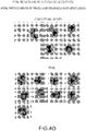
- -1 shown in FIG. 4H Chemical compound 0.000 description 3
- 239000011550 stock solution Substances 0.000 description 3
- QCDWFXQBSFUVSP-UHFFFAOYSA-N 2-phenoxyethanol Chemical compound OCCOC1=CC=CC=C1 QCDWFXQBSFUVSP-UHFFFAOYSA-N 0.000 description 2
- WRMNZCZEMHIOCP-UHFFFAOYSA-N 2-phenylethanol Chemical compound OCCC1=CC=CC=C1 WRMNZCZEMHIOCP-UHFFFAOYSA-N 0.000 description 2
- FJKROLUGYXJWQN-UHFFFAOYSA-N 4-hydroxybenzoic acid Chemical class OC(=O)C1=CC=C(O)C=C1 FJKROLUGYXJWQN-UHFFFAOYSA-N 0.000 description 2
- FTOAOBMCPZCFFF-UHFFFAOYSA-N 5,5-diethylbarbituric acid Chemical compound CCC1(CC)C(=O)NC(=O)NC1=O FTOAOBMCPZCFFF-UHFFFAOYSA-N 0.000 description 2
- 208000035143 Bacterial infection Diseases 0.000 description 2
- VTYYLEPIZMXCLO-UHFFFAOYSA-L Calcium carbonate Chemical compound [Ca+2].[O-]C([O-])=O VTYYLEPIZMXCLO-UHFFFAOYSA-L 0.000 description 2
- 206010053567 Coagulopathies Diseases 0.000 description 2
- 239000003109 Disodium ethylene diamine tetraacetate Substances 0.000 description 2
- 206010063045 Effusion Diseases 0.000 description 2
- XEEYBQQBJWHFJM-UHFFFAOYSA-N Iron Chemical compound [Fe] XEEYBQQBJWHFJM-UHFFFAOYSA-N 0.000 description 2
- BAVYZALUXZFZLV-UHFFFAOYSA-N Methylamine Chemical compound NC BAVYZALUXZFZLV-UHFFFAOYSA-N 0.000 description 2
- FSVCELGFZIQNCK-UHFFFAOYSA-N N,N-bis(2-hydroxyethyl)glycine Chemical compound OCCN(CCO)CC(O)=O FSVCELGFZIQNCK-UHFFFAOYSA-N 0.000 description 2
- SEQKRHFRPICQDD-UHFFFAOYSA-N N-tris(hydroxymethyl)methylglycine Chemical compound OCC(CO)(CO)[NH2+]CC([O-])=O SEQKRHFRPICQDD-UHFFFAOYSA-N 0.000 description 2
- PMZURENOXWZQFD-UHFFFAOYSA-L Sodium Sulfate Chemical compound [Na+].[Na+].[O-]S([O-])(=O)=O PMZURENOXWZQFD-UHFFFAOYSA-L 0.000 description 2
- 208000036142 Viral infection Diseases 0.000 description 2
- 230000002378 acidificating effect Effects 0.000 description 2
- 239000000654 additive Substances 0.000 description 2
- 229910052784 alkaline earth metal Inorganic materials 0.000 description 2
- 150000001342 alkaline earth metals Chemical class 0.000 description 2
- 230000000844 anti-bacterial effect Effects 0.000 description 2
- 239000003146 anticoagulant agent Substances 0.000 description 2
- 229940127219 anticoagulant drug Drugs 0.000 description 2
- 230000001580 bacterial effect Effects 0.000 description 2
- 208000022362 bacterial infectious disease Diseases 0.000 description 2
- RQPZNWPYLFFXCP-UHFFFAOYSA-L barium dihydroxide Chemical compound [OH-].[OH-].[Ba+2] RQPZNWPYLFFXCP-UHFFFAOYSA-L 0.000 description 2
- WPYMKLBDIGXBTP-UHFFFAOYSA-N benzoic acid Chemical compound OC(=O)C1=CC=CC=C1 WPYMKLBDIGXBTP-UHFFFAOYSA-N 0.000 description 2
- 230000002146 bilateral effect Effects 0.000 description 2
- 210000003855 cell nucleus Anatomy 0.000 description 2
- 239000003153 chemical reaction reagent Substances 0.000 description 2
- OSASVXMJTNOKOY-UHFFFAOYSA-N chlorobutanol Chemical compound CC(C)(O)C(Cl)(Cl)Cl OSASVXMJTNOKOY-UHFFFAOYSA-N 0.000 description 2
- 230000035602 clotting Effects 0.000 description 2
- 150000001875 compounds Chemical class 0.000 description 2
- 239000012470 diluted sample Substances 0.000 description 2
- XBDQKXXYIPTUBI-UHFFFAOYSA-N dimethylselenoniopropionate Natural products CCC(O)=O XBDQKXXYIPTUBI-UHFFFAOYSA-N 0.000 description 2
- 235000019301 disodium ethylene diamine tetraacetate Nutrition 0.000 description 2
- 229910000397 disodium phosphate Inorganic materials 0.000 description 2
- 235000019800 disodium phosphate Nutrition 0.000 description 2
- 230000002708 enhancing effect Effects 0.000 description 2
- 230000006870 function Effects 0.000 description 2
- 230000002538 fungal effect Effects 0.000 description 2
- 239000000417 fungicide Substances 0.000 description 2
- 210000003714 granulocyte Anatomy 0.000 description 2
- 230000003862 health status Effects 0.000 description 2
- 230000006872 improvement Effects 0.000 description 2
- 229910052500 inorganic mineral Chemical class 0.000 description 2
- 230000002934 lysing effect Effects 0.000 description 2
- BDAGIHXWWSANSR-UHFFFAOYSA-N methanoic acid Natural products OC=O BDAGIHXWWSANSR-UHFFFAOYSA-N 0.000 description 2
- 239000011707 mineral Chemical class 0.000 description 2
- 235000010755 mineral Nutrition 0.000 description 2
- 229910000402 monopotassium phosphate Inorganic materials 0.000 description 2
- CGVLVOOFCGWBCS-RGDJUOJXSA-N n-octyl β-d-thioglucopyranoside Chemical compound CCCCCCCCS[C@@H]1O[C@H](CO)[C@@H](O)[C@H](O)[C@H]1O CGVLVOOFCGWBCS-RGDJUOJXSA-N 0.000 description 2
- 150000007524 organic acids Chemical class 0.000 description 2
- 235000005985 organic acids Nutrition 0.000 description 2
- 150000007530 organic bases Chemical class 0.000 description 2
- 239000013618 particulate matter Substances 0.000 description 2
- 229960005323 phenoxyethanol Drugs 0.000 description 2
- 229920000223 polyglycerol Polymers 0.000 description 2
- 235000013824 polyphenols Nutrition 0.000 description 2
- 238000002360 preparation method Methods 0.000 description 2
- 239000003755 preservative agent Substances 0.000 description 2
- 229960004919 procaine Drugs 0.000 description 2
- MFDFERRIHVXMIY-UHFFFAOYSA-N procaine Chemical compound CCN(CC)CCOC(=O)C1=CC=C(N)C=C1 MFDFERRIHVXMIY-UHFFFAOYSA-N 0.000 description 2
- UMJSCPRVCHMLSP-UHFFFAOYSA-N pyridine Natural products COC1=CC=CN=C1 UMJSCPRVCHMLSP-UHFFFAOYSA-N 0.000 description 2
- YGSDEFSMJLZEOE-UHFFFAOYSA-N salicylic acid Chemical compound OC(=O)C1=CC=CC=C1O YGSDEFSMJLZEOE-UHFFFAOYSA-N 0.000 description 2
- 238000005070 sampling Methods 0.000 description 2
- 229910052938 sodium sulfate Inorganic materials 0.000 description 2
- 235000011152 sodium sulphate Nutrition 0.000 description 2
- UUCCCPNEFXQJEL-UHFFFAOYSA-L strontium dihydroxide Chemical compound [OH-].[OH-].[Sr+2] UUCCCPNEFXQJEL-UHFFFAOYSA-L 0.000 description 2
- 229910001866 strontium hydroxide Inorganic materials 0.000 description 2
- 230000009385 viral infection Effects 0.000 description 2
- 239000004034 viscosity adjusting agent Substances 0.000 description 2
- MXOAEAUPQDYUQM-QMMMGPOBSA-N (S)-chlorphenesin Chemical compound OC[C@H](O)COC1=CC=C(Cl)C=C1 MXOAEAUPQDYUQM-QMMMGPOBSA-N 0.000 description 1
- JYEUMXHLPRZUAT-UHFFFAOYSA-N 1,2,3-triazine Chemical compound C1=CN=NN=C1 JYEUMXHLPRZUAT-UHFFFAOYSA-N 0.000 description 1
- VUWCWMOCWKCZTA-UHFFFAOYSA-N 1,2-thiazol-4-one Chemical class O=C1CSN=C1 VUWCWMOCWKCZTA-UHFFFAOYSA-N 0.000 description 1
- HYZJCKYKOHLVJF-UHFFFAOYSA-N 1H-benzimidazole Chemical compound C1=CC=C2NC=NC2=C1 HYZJCKYKOHLVJF-UHFFFAOYSA-N 0.000 description 1
- QZTKDVCDBIDYMD-UHFFFAOYSA-N 2,2'-[(2-amino-2-oxoethyl)imino]diacetic acid Chemical compound NC(=O)CN(CC(O)=O)CC(O)=O QZTKDVCDBIDYMD-UHFFFAOYSA-N 0.000 description 1
- IHPYMWDTONKSCO-UHFFFAOYSA-N 2,2'-piperazine-1,4-diylbisethanesulfonic acid Chemical compound OS(=O)(=O)CCN1CCN(CCS(O)(=O)=O)CC1 IHPYMWDTONKSCO-UHFFFAOYSA-N 0.000 description 1
- DBHODFSFBXJZNY-UHFFFAOYSA-N 2,4-dichlorobenzyl alcohol Chemical compound OCC1=CC=C(Cl)C=C1Cl DBHODFSFBXJZNY-UHFFFAOYSA-N 0.000 description 1
- XNCSCQSQSGDGES-UHFFFAOYSA-N 2-[2-[bis(carboxymethyl)amino]propyl-(carboxymethyl)amino]acetic acid Chemical compound OC(=O)CN(CC(O)=O)C(C)CN(CC(O)=O)CC(O)=O XNCSCQSQSGDGES-UHFFFAOYSA-N 0.000 description 1
- JKMHFZQWWAIEOD-UHFFFAOYSA-N 2-[4-(2-hydroxyethyl)piperazin-1-yl]ethanesulfonic acid Chemical compound OCC[NH+]1CCN(CCS([O-])(=O)=O)CC1 JKMHFZQWWAIEOD-UHFFFAOYSA-N 0.000 description 1
- YGDVXSDNEFDTGV-UHFFFAOYSA-N 2-[6-[bis(carboxymethyl)amino]hexyl-(carboxymethyl)amino]acetic acid Chemical compound OC(=O)CN(CC(O)=O)CCCCCCN(CC(O)=O)CC(O)=O YGDVXSDNEFDTGV-UHFFFAOYSA-N 0.000 description 1
- WYMDDFRYORANCC-UHFFFAOYSA-N 2-[[3-[bis(carboxymethyl)amino]-2-hydroxypropyl]-(carboxymethyl)amino]acetic acid Chemical compound OC(=O)CN(CC(O)=O)CC(O)CN(CC(O)=O)CC(O)=O WYMDDFRYORANCC-UHFFFAOYSA-N 0.000 description 1
- AJTVSSFTXWNIRG-UHFFFAOYSA-N 2-[bis(2-hydroxyethyl)amino]ethanesulfonic acid Chemical compound OCC[NH+](CCO)CCS([O-])(=O)=O AJTVSSFTXWNIRG-UHFFFAOYSA-N 0.000 description 1
- DHVLDKHFGIVEIP-UHFFFAOYSA-N 2-bromo-2-(bromomethyl)pentanedinitrile Chemical compound BrCC(Br)(C#N)CCC#N DHVLDKHFGIVEIP-UHFFFAOYSA-N 0.000 description 1
- LVQFQZZGTZFUNF-UHFFFAOYSA-N 2-hydroxy-3-[4-(2-hydroxy-3-sulfonatopropyl)piperazine-1,4-diium-1-yl]propane-1-sulfonate Chemical compound OS(=O)(=O)CC(O)CN1CCN(CC(O)CS(O)(=O)=O)CC1 LVQFQZZGTZFUNF-UHFFFAOYSA-N 0.000 description 1
- 229940100555 2-methyl-4-isothiazolin-3-one Drugs 0.000 description 1
- DVLFYONBTKHTER-UHFFFAOYSA-N 3-(N-morpholino)propanesulfonic acid Chemical compound OS(=O)(=O)CCCN1CCOCC1 DVLFYONBTKHTER-UHFFFAOYSA-N 0.000 description 1
- NUFBIAUZAMHTSP-UHFFFAOYSA-N 3-(n-morpholino)-2-hydroxypropanesulfonic acid Chemical compound OS(=O)(=O)CC(O)CN1CCOCC1 NUFBIAUZAMHTSP-UHFFFAOYSA-N 0.000 description 1
- UMCMPZBLKLEWAF-BCTGSCMUSA-N 3-[(3-cholamidopropyl)dimethylammonio]propane-1-sulfonate Chemical compound C([C@H]1C[C@H]2O)[C@H](O)CC[C@]1(C)[C@@H]1[C@@H]2[C@@H]2CC[C@H]([C@@H](CCC(=O)NCCC[N+](C)(C)CCCS([O-])(=O)=O)C)[C@@]2(C)[C@@H](O)C1 UMCMPZBLKLEWAF-BCTGSCMUSA-N 0.000 description 1
- RZQXOGQSPBYUKH-UHFFFAOYSA-N 3-[[1,3-dihydroxy-2-(hydroxymethyl)propan-2-yl]azaniumyl]-2-hydroxypropane-1-sulfonate Chemical compound OCC(CO)(CO)NCC(O)CS(O)(=O)=O RZQXOGQSPBYUKH-UHFFFAOYSA-N 0.000 description 1
- XCBLFURAFHFFJF-UHFFFAOYSA-N 3-[bis(2-hydroxyethyl)azaniumyl]-2-hydroxypropane-1-sulfonate Chemical compound OCCN(CCO)CC(O)CS(O)(=O)=O XCBLFURAFHFFJF-UHFFFAOYSA-N 0.000 description 1
- GUQQBLRVXOUDTN-XOHPMCGNSA-N 3-[dimethyl-[3-[[(4r)-4-[(3r,5s,7r,8r,9s,10s,12s,13r,14s,17r)-3,7,12-trihydroxy-10,13-dimethyl-2,3,4,5,6,7,8,9,11,12,14,15,16,17-tetradecahydro-1h-cyclopenta[a]phenanthren-17-yl]pentanoyl]amino]propyl]azaniumyl]-2-hydroxypropane-1-sulfonate Chemical compound C([C@H]1C[C@H]2O)[C@H](O)CC[C@]1(C)[C@@H]1[C@@H]2[C@@H]2CC[C@H]([C@@H](CCC(=O)NCCC[N+](C)(C)CC(O)CS([O-])(=O)=O)C)[C@@]2(C)[C@@H](O)C1 GUQQBLRVXOUDTN-XOHPMCGNSA-N 0.000 description 1
- 229940099451 3-iodo-2-propynylbutylcarbamate Drugs 0.000 description 1
- WYVVKGNFXHOCQV-UHFFFAOYSA-N 3-iodoprop-2-yn-1-yl butylcarbamate Chemical compound CCCCNC(=O)OCC#CI WYVVKGNFXHOCQV-UHFFFAOYSA-N 0.000 description 1
- OSWFIVFLDKOXQC-UHFFFAOYSA-N 4-(3-methoxyphenyl)aniline Chemical compound COC1=CC=CC(C=2C=CC(N)=CC=2)=C1 OSWFIVFLDKOXQC-UHFFFAOYSA-N 0.000 description 1
- OSDLLIBGSJNGJE-UHFFFAOYSA-N 4-chloro-3,5-dimethylphenol Chemical compound CC1=CC(O)=CC(C)=C1Cl OSDLLIBGSJNGJE-UHFFFAOYSA-N 0.000 description 1
- QYYMDNHUJFIDDQ-UHFFFAOYSA-N 5-chloro-2-methyl-1,2-thiazol-3-one;2-methyl-1,2-thiazol-3-one Chemical compound CN1SC=CC1=O.CN1SC(Cl)=CC1=O QYYMDNHUJFIDDQ-UHFFFAOYSA-N 0.000 description 1
- 229940100484 5-chloro-2-methyl-4-isothiazolin-3-one Drugs 0.000 description 1
- 239000007991 ACES buffer Substances 0.000 description 1
- 239000007988 ADA buffer Substances 0.000 description 1
- 208000007848 Alcoholism Diseases 0.000 description 1
- 239000004254 Ammonium phosphate Substances 0.000 description 1
- 108700016232 Arg(2)-Sar(4)- dermorphin (1-4) Proteins 0.000 description 1
- 208000010839 B-cell chronic lymphocytic leukemia Diseases 0.000 description 1
- 239000007992 BES buffer Substances 0.000 description 1
- 239000005711 Benzoic acid Substances 0.000 description 1
- LVDKZNITIUWNER-UHFFFAOYSA-N Bronopol Chemical compound OCC(Br)(CO)[N+]([O-])=O LVDKZNITIUWNER-UHFFFAOYSA-N 0.000 description 1
- GHXZTYHSJHQHIJ-UHFFFAOYSA-N Chlorhexidine Chemical compound C=1C=C(Cl)C=CC=1NC(N)=NC(N)=NCCCCCCN=C(N)N=C(N)NC1=CC=C(Cl)C=C1 GHXZTYHSJHQHIJ-UHFFFAOYSA-N 0.000 description 1
- KRKNYBCHXYNGOX-UHFFFAOYSA-K Citrate Chemical compound [O-]C(=O)CC(O)(CC([O-])=O)C([O-])=O KRKNYBCHXYNGOX-UHFFFAOYSA-K 0.000 description 1
- 206010009900 Colitis ulcerative Diseases 0.000 description 1
- 208000011231 Crohn disease Diseases 0.000 description 1
- FCKYPQBAHLOOJQ-UHFFFAOYSA-N Cyclohexane-1,2-diaminetetraacetic acid Chemical compound OC(=O)CN(CC(O)=O)C1CCCCC1N(CC(O)=O)CC(O)=O FCKYPQBAHLOOJQ-UHFFFAOYSA-N 0.000 description 1
- 239000004287 Dehydroacetic acid Substances 0.000 description 1
- 240000001973 Ficus microcarpa Species 0.000 description 1
- 241000233866 Fungi Species 0.000 description 1
- 239000006173 Good's buffer Substances 0.000 description 1
- 239000007995 HEPES buffer Substances 0.000 description 1
- OWXMKDGYPWMGEB-UHFFFAOYSA-N HEPPS Chemical compound OCCN1CCN(CCCS(O)(=O)=O)CC1 OWXMKDGYPWMGEB-UHFFFAOYSA-N 0.000 description 1
- GIZQLVPDAOBAFN-UHFFFAOYSA-N HEPPSO Chemical compound OCCN1CCN(CC(O)CS(O)(=O)=O)CC1 GIZQLVPDAOBAFN-UHFFFAOYSA-N 0.000 description 1
- 208000031886 HIV Infections Diseases 0.000 description 1
- 208000037357 HIV infectious disease Diseases 0.000 description 1
- 206010020751 Hypersensitivity Diseases 0.000 description 1
- HNDVDQJCIGZPNO-YFKPBYRVSA-N L-histidine Chemical compound OC(=O)[C@@H](N)CC1=CN=CN1 HNDVDQJCIGZPNO-YFKPBYRVSA-N 0.000 description 1
- 206010025323 Lymphomas Diseases 0.000 description 1
- 239000007993 MOPS buffer Substances 0.000 description 1
- 206010027540 Microcytosis Diseases 0.000 description 1
- DBXNUXBLKRLWFA-UHFFFAOYSA-N N-(2-acetamido)-2-aminoethanesulfonic acid Chemical compound NC(=O)CNCCS(O)(=O)=O DBXNUXBLKRLWFA-UHFFFAOYSA-N 0.000 description 1
- JOCBASBOOFNAJA-UHFFFAOYSA-N N-tris(hydroxymethyl)methyl-2-aminoethanesulfonic acid Chemical compound OCC(CO)(CO)NCCS(O)(=O)=O JOCBASBOOFNAJA-UHFFFAOYSA-N 0.000 description 1
- 241000047703 Nonion Species 0.000 description 1
- 239000007990 PIPES buffer Substances 0.000 description 1
- 229910019142 PO4 Inorganic materials 0.000 description 1
- 208000030852 Parasitic disease Diseases 0.000 description 1
- 229920001090 Polyaminopropyl biguanide Polymers 0.000 description 1
- 229920001213 Polysorbate 20 Polymers 0.000 description 1
- 229920001214 Polysorbate 60 Polymers 0.000 description 1
- KWYUFKZDYYNOTN-UHFFFAOYSA-M Potassium hydroxide Chemical compound [OH-].[K+] KWYUFKZDYYNOTN-UHFFFAOYSA-M 0.000 description 1
- 206010039207 Rocky Mountain Spotted Fever Diseases 0.000 description 1
- CZMRCDWAGMRECN-UGDNZRGBSA-N Sucrose Chemical compound O[C@H]1[C@H](O)[C@@H](CO)O[C@@]1(CO)O[C@@H]1[C@H](O)[C@@H](O)[C@H](O)[C@@H](CO)O1 CZMRCDWAGMRECN-UGDNZRGBSA-N 0.000 description 1
- 229930006000 Sucrose Natural products 0.000 description 1
- UZMAPBJVXOGOFT-UHFFFAOYSA-N Syringetin Natural products COC1=C(O)C(OC)=CC(C2=C(C(=O)C3=C(O)C=C(O)C=C3O2)O)=C1 UZMAPBJVXOGOFT-UHFFFAOYSA-N 0.000 description 1
- 239000007994 TES buffer Substances 0.000 description 1
- 208000002903 Thalassemia Diseases 0.000 description 1
- FZWLAAWBMGSTSO-UHFFFAOYSA-N Thiazole Chemical compound C1=CSC=N1 FZWLAAWBMGSTSO-UHFFFAOYSA-N 0.000 description 1
- 239000007997 Tricine buffer Substances 0.000 description 1
- 239000013504 Triton X-100 Substances 0.000 description 1
- 229920004890 Triton X-100 Polymers 0.000 description 1
- 208000034953 Twin anemia-polycythemia sequence Diseases 0.000 description 1
- 201000006704 Ulcerative Colitis Diseases 0.000 description 1
- HMNDRWDQGZZYIC-UHFFFAOYSA-N [2-(phosphonomethylamino)ethylamino]methylphosphonic acid Chemical compound OP(O)(=O)CNCCNCP(O)(O)=O HMNDRWDQGZZYIC-UHFFFAOYSA-N 0.000 description 1
- AXIKDPDWFVPGOD-UHFFFAOYSA-O [7-(dimethylamino)phenothiazin-3-ylidene]-dimethylazanium;2-(2,4,5,7-tetrabromo-3,6-dihydroxyxanthen-10-ium-9-yl)benzoic acid Chemical compound C1=CC(=[N+](C)C)C=C2SC3=CC(N(C)C)=CC=C3N=C21.OC(=O)C1=CC=CC=C1C1=C(C=C(Br)C(O)=C2Br)C2=[O+]C2=C1C=C(Br)C(O)=C2Br AXIKDPDWFVPGOD-UHFFFAOYSA-O 0.000 description 1
- NBVZMBLJRHUOJR-UHFFFAOYSA-N [amino-[4-[6-[4-[amino(azaniumylidene)methyl]phenoxy]hexoxy]phenyl]methylidene]azanium;2-hydroxyethanesulfonate Chemical compound OCCS(O)(=O)=O.OCCS(O)(=O)=O.C1=CC(C(=N)N)=CC=C1OCCCCCCOC1=CC=C(C(N)=N)C=C1 NBVZMBLJRHUOJR-UHFFFAOYSA-N 0.000 description 1
- 230000001133 acceleration Effects 0.000 description 1
- 239000008186 active pharmaceutical agent Substances 0.000 description 1
- 230000001154 acute effect Effects 0.000 description 1
- 201000007930 alcohol dependence Diseases 0.000 description 1
- 150000001298 alcohols Chemical class 0.000 description 1
- 229910052783 alkali metal Inorganic materials 0.000 description 1
- 150000001340 alkali metals Chemical class 0.000 description 1
- 125000000217 alkyl group Chemical group 0.000 description 1
- 208000030961 allergic reaction Diseases 0.000 description 1
- 229910000148 ammonium phosphate Inorganic materials 0.000 description 1
- 235000019289 ammonium phosphates Nutrition 0.000 description 1
- 210000004381 amniotic fluid Anatomy 0.000 description 1
- 208000007502 anemia Diseases 0.000 description 1
- 125000000129 anionic group Chemical group 0.000 description 1
- 239000003945 anionic surfactant Substances 0.000 description 1
- 238000013459 approach Methods 0.000 description 1
- 210000003567 ascitic fluid Anatomy 0.000 description 1
- 208000006673 asthma Diseases 0.000 description 1
- 229960002319 barbital Drugs 0.000 description 1
- 229910001863 barium hydroxide Inorganic materials 0.000 description 1
- 239000002585 base Substances 0.000 description 1
- 230000006399 behavior Effects 0.000 description 1
- 229960000686 benzalkonium chloride Drugs 0.000 description 1
- 229960001950 benzethonium chloride Drugs 0.000 description 1
- UREZNYTWGJKWBI-UHFFFAOYSA-M benzethonium chloride Chemical compound [Cl-].C1=CC(C(C)(C)CC(C)(C)C)=CC=C1OCCOCC[N+](C)(C)CC1=CC=CC=C1 UREZNYTWGJKWBI-UHFFFAOYSA-M 0.000 description 1
- 235000010233 benzoic acid Nutrition 0.000 description 1
- 229960004365 benzoic acid Drugs 0.000 description 1
- CADWTSSKOVRVJC-UHFFFAOYSA-N benzyl(dimethyl)azanium;chloride Chemical compound [Cl-].C[NH+](C)CC1=CC=CC=C1 CADWTSSKOVRVJC-UHFFFAOYSA-N 0.000 description 1
- 239000007998 bicine buffer Substances 0.000 description 1
- 238000001574 biopsy Methods 0.000 description 1
- OWMVSZAMULFTJU-UHFFFAOYSA-N bis-tris Chemical compound OCCN(CCO)C(CO)(CO)CO OWMVSZAMULFTJU-UHFFFAOYSA-N 0.000 description 1
- 239000012503 blood component Substances 0.000 description 1
- 238000009534 blood test Methods 0.000 description 1
- 229910000019 calcium carbonate Inorganic materials 0.000 description 1
- 235000010216 calcium carbonate Nutrition 0.000 description 1
- AXCZMVOFGPJBDE-UHFFFAOYSA-L calcium dihydroxide Chemical compound [OH-].[OH-].[Ca+2] AXCZMVOFGPJBDE-UHFFFAOYSA-L 0.000 description 1
- 238000004422 calculation algorithm Methods 0.000 description 1
- 238000004364 calculation method Methods 0.000 description 1
- 125000002091 cationic group Chemical group 0.000 description 1
- 239000003093 cationic surfactant Substances 0.000 description 1
- 150000001768 cations Chemical class 0.000 description 1
- 238000004113 cell culture Methods 0.000 description 1
- 230000006037 cell lysis Effects 0.000 description 1
- 239000006285 cell suspension Substances 0.000 description 1
- 210000002421 cell wall Anatomy 0.000 description 1
- 229960003260 chlorhexidine Drugs 0.000 description 1
- VXIVSQZSERGHQP-UHFFFAOYSA-N chloroacetamide Chemical compound NC(=O)CCl VXIVSQZSERGHQP-UHFFFAOYSA-N 0.000 description 1
- 229960004926 chlorobutanol Drugs 0.000 description 1
- DHNRXBZYEKSXIM-UHFFFAOYSA-N chloromethylisothiazolinone Chemical compound CN1SC(Cl)=CC1=O DHNRXBZYEKSXIM-UHFFFAOYSA-N 0.000 description 1
- 229960005443 chloroxylenol Drugs 0.000 description 1
- 229960003993 chlorphenesin Drugs 0.000 description 1
- 201000010902 chronic myelomonocytic leukemia Diseases 0.000 description 1
- 150000001860 citric acid derivatives Chemical class 0.000 description 1
- 238000004140 cleaning Methods 0.000 description 1
- 230000003247 decreasing effect Effects 0.000 description 1
- PGRHXDWITVMQBC-UHFFFAOYSA-N dehydroacetic acid Natural products CC(=O)C1C(=O)OC(C)=CC1=O PGRHXDWITVMQBC-UHFFFAOYSA-N 0.000 description 1
- 235000019258 dehydroacetic acid Nutrition 0.000 description 1
- JEQRBTDTEKWZBW-UHFFFAOYSA-N dehydroacetic acid Chemical compound CC(=O)C1=C(O)OC(C)=CC1=O JEQRBTDTEKWZBW-UHFFFAOYSA-N 0.000 description 1
- 229940061632 dehydroacetic acid Drugs 0.000 description 1
- OJSUWTDDXLCUFR-YVKIRAPASA-N deoxy-bigchap Chemical compound C([C@@H]1CC2)[C@@H](O)CC[C@]1(C)[C@@H]1[C@@H]2[C@@H]2CC[C@@H]([C@@H](CCC(=O)N(CCCNC(=O)[C@@H](O)[C@@H](O)[C@H](O)[C@H](O)CO)CCCNC(=O)[C@@H](O)[C@@H](O)[C@H](O)[C@H](O)CO)C)[C@@]2(C)[C@H](O)C1 OJSUWTDDXLCUFR-YVKIRAPASA-N 0.000 description 1
- 238000013461 design Methods 0.000 description 1
- 238000011161 development Methods 0.000 description 1
- 238000002405 diagnostic procedure Methods 0.000 description 1
- 238000012631 diagnostic technique Methods 0.000 description 1
- MNNHAPBLZZVQHP-UHFFFAOYSA-N diammonium hydrogen phosphate Chemical compound [NH4+].[NH4+].OP([O-])([O-])=O MNNHAPBLZZVQHP-UHFFFAOYSA-N 0.000 description 1
- 229960004698 dichlorobenzyl alcohol Drugs 0.000 description 1
- GPLRAVKSCUXZTP-UHFFFAOYSA-N diglycerol Chemical compound OCC(O)COCC(O)CO GPLRAVKSCUXZTP-UHFFFAOYSA-N 0.000 description 1
- KCFYHBSOLOXZIF-UHFFFAOYSA-N dihydrochrysin Natural products COC1=C(O)C(OC)=CC(C2OC3=CC(O)=CC(O)=C3C(=O)C2)=C1 KCFYHBSOLOXZIF-UHFFFAOYSA-N 0.000 description 1
- OGGXGZAMXPVRFZ-UHFFFAOYSA-N dimethylarsinic acid Chemical class C[As](C)(O)=O OGGXGZAMXPVRFZ-UHFFFAOYSA-N 0.000 description 1
- 235000011180 diphosphates Nutrition 0.000 description 1
- 208000035475 disorder Diseases 0.000 description 1
- 239000003814 drug Substances 0.000 description 1
- 239000000975 dye Substances 0.000 description 1
- AWZOLILCOUMRDG-UHFFFAOYSA-N edifenphos Chemical compound C=1C=CC=CC=1SP(=O)(OCC)SC1=CC=CC=C1 AWZOLILCOUMRDG-UHFFFAOYSA-N 0.000 description 1
- 239000003623 enhancer Substances 0.000 description 1
- BEFDCLMNVWHSGT-UHFFFAOYSA-N ethenylcyclopentane Chemical compound C=CC1CCCC1 BEFDCLMNVWHSGT-UHFFFAOYSA-N 0.000 description 1
- DEFVIWRASFVYLL-UHFFFAOYSA-N ethylene glycol bis(2-aminoethyl)tetraacetic acid Chemical compound OC(=O)CN(CC(O)=O)CCOCCOCCN(CC(O)=O)CC(O)=O DEFVIWRASFVYLL-UHFFFAOYSA-N 0.000 description 1
- IFQUWYZCAGRUJN-UHFFFAOYSA-N ethylenediaminediacetic acid Chemical compound OC(=O)CNCCNCC(O)=O IFQUWYZCAGRUJN-UHFFFAOYSA-N 0.000 description 1
- 238000011156 evaluation Methods 0.000 description 1
- 238000002474 experimental method Methods 0.000 description 1
- 210000000416 exudates and transudate Anatomy 0.000 description 1
- 230000002550 fecal effect Effects 0.000 description 1
- 230000001605 fetal effect Effects 0.000 description 1
- 238000011010 flushing procedure Methods 0.000 description 1
- 235000019253 formic acid Nutrition 0.000 description 1
- 229940013688 formic acid Drugs 0.000 description 1
- 230000000855 fungicidal effect Effects 0.000 description 1
- 239000011521 glass Substances 0.000 description 1
- 238000010438 heat treatment Methods 0.000 description 1
- 229960001915 hexamidine Drugs 0.000 description 1
- HNDVDQJCIGZPNO-UHFFFAOYSA-N histidine Natural products OC(=O)C(N)CC1=CN=CN1 HNDVDQJCIGZPNO-UHFFFAOYSA-N 0.000 description 1
- 230000002962 histologic effect Effects 0.000 description 1
- 208000033519 human immunodeficiency virus infectious disease Diseases 0.000 description 1
- 201000006747 infectious mononucleosis Diseases 0.000 description 1
- 230000002401 inhibitory effect Effects 0.000 description 1
- 239000002563 ionic surfactant Substances 0.000 description 1
- 229910052742 iron Inorganic materials 0.000 description 1
- MGIYRDNGCNKGJU-UHFFFAOYSA-N isothiazolinone Chemical compound O=C1C=CSN1 MGIYRDNGCNKGJU-UHFFFAOYSA-N 0.000 description 1
- 208000032839 leukemia Diseases 0.000 description 1
- DJQJFMSHHYAZJD-UHFFFAOYSA-N lidofenin Chemical compound CC1=CC=CC(C)=C1NC(=O)CN(CC(O)=O)CC(O)=O DJQJFMSHHYAZJD-UHFFFAOYSA-N 0.000 description 1
- 230000000670 limiting effect Effects 0.000 description 1
- GVALZJMUIHGIMD-UHFFFAOYSA-H magnesium phosphate Chemical compound [Mg+2].[Mg+2].[Mg+2].[O-]P([O-])([O-])=O.[O-]P([O-])([O-])=O GVALZJMUIHGIMD-UHFFFAOYSA-H 0.000 description 1
- 239000004137 magnesium phosphate Substances 0.000 description 1
- 229960002261 magnesium phosphate Drugs 0.000 description 1
- 229910000157 magnesium phosphate Inorganic materials 0.000 description 1
- 235000010994 magnesium phosphates Nutrition 0.000 description 1
- 239000011976 maleic acid Substances 0.000 description 1
- 238000004519 manufacturing process Methods 0.000 description 1
- 238000005259 measurement Methods 0.000 description 1
- 238000010339 medical test Methods 0.000 description 1
- 229910052751 metal Inorganic materials 0.000 description 1
- 239000002184 metal Substances 0.000 description 1
- 150000002739 metals Chemical class 0.000 description 1
- BEGLCMHJXHIJLR-UHFFFAOYSA-N methylisothiazolinone Chemical compound CN1SC=CC1=O BEGLCMHJXHIJLR-UHFFFAOYSA-N 0.000 description 1
- 238000001000 micrograph Methods 0.000 description 1
- 238000000386 microscopy Methods 0.000 description 1
- 230000003278 mimic effect Effects 0.000 description 1
- 238000012544 monitoring process Methods 0.000 description 1
- 229940111688 monobasic potassium phosphate Drugs 0.000 description 1
- 229910000403 monosodium phosphate Inorganic materials 0.000 description 1
- 235000019799 monosodium phosphate Nutrition 0.000 description 1
- PJUIMOJAAPLTRJ-UHFFFAOYSA-N monothioglycerol Chemical compound OCC(O)CS PJUIMOJAAPLTRJ-UHFFFAOYSA-N 0.000 description 1
- GKTNLYAAZKKMTQ-UHFFFAOYSA-N n-[bis(dimethylamino)phosphinimyl]-n-methylmethanamine Chemical compound CN(C)P(=N)(N(C)C)N(C)C GKTNLYAAZKKMTQ-UHFFFAOYSA-N 0.000 description 1
- SBWGZAXBCCNRTM-CTHBEMJXSA-N n-methyl-n-[(2s,3r,4r,5r)-2,3,4,5,6-pentahydroxyhexyl]octanamide Chemical compound CCCCCCCC(=O)N(C)C[C@H](O)[C@@H](O)[C@H](O)[C@H](O)CO SBWGZAXBCCNRTM-CTHBEMJXSA-N 0.000 description 1
- 239000013642 negative control Substances 0.000 description 1
- 210000000441 neoplastic stem cell Anatomy 0.000 description 1
- 239000002736 nonionic surfactant Substances 0.000 description 1
- 231100000252 nontoxic Toxicity 0.000 description 1
- 230000003000 nontoxic effect Effects 0.000 description 1
- 150000002913 oxalic acids Chemical class 0.000 description 1
- 230000003647 oxidation Effects 0.000 description 1
- 238000007254 oxidation reaction Methods 0.000 description 1
- 230000036961 partial effect Effects 0.000 description 1
- 230000001575 pathological effect Effects 0.000 description 1
- VLTRZXGMWDSKGL-UHFFFAOYSA-N perchloric acid Chemical class OCl(=O)(=O)=O VLTRZXGMWDSKGL-UHFFFAOYSA-N 0.000 description 1
- 239000008191 permeabilizing agent Substances 0.000 description 1
- ISWSIDIOOBJBQZ-UHFFFAOYSA-N phenol group Chemical group C1(=CC=CC=C1)O ISWSIDIOOBJBQZ-UHFFFAOYSA-N 0.000 description 1
- WVDDGKGOMKODPV-ZQBYOMGUSA-N phenyl(114C)methanol Chemical compound O[14CH2]C1=CC=CC=C1 WVDDGKGOMKODPV-ZQBYOMGUSA-N 0.000 description 1
- 235000021317 phosphate Nutrition 0.000 description 1
- 150000003013 phosphoric acid derivatives Chemical class 0.000 description 1
- 230000004962 physiological condition Effects 0.000 description 1
- 210000004910 pleural fluid Anatomy 0.000 description 1
- 229920001992 poloxamer 407 Polymers 0.000 description 1
- 229940093424 polyaminopropyl biguanide Drugs 0.000 description 1
- 229920005862 polyol Polymers 0.000 description 1
- 150000003077 polyols Chemical class 0.000 description 1
- 239000000256 polyoxyethylene sorbitan monolaurate Substances 0.000 description 1
- 235000010486 polyoxyethylene sorbitan monolaurate Nutrition 0.000 description 1
- 239000013641 positive control Substances 0.000 description 1
- 239000000843 powder Substances 0.000 description 1
- 239000002244 precipitate Substances 0.000 description 1
- 238000001556 precipitation Methods 0.000 description 1
- 239000000047 product Substances 0.000 description 1
- 235000019260 propionic acid Nutrition 0.000 description 1
- 229940095574 propionic acid Drugs 0.000 description 1
- FGVVTMRZYROCTH-UHFFFAOYSA-N pyridine-2-thiol N-oxide Chemical compound [O-][N+]1=CC=CC=C1S FGVVTMRZYROCTH-UHFFFAOYSA-N 0.000 description 1
- 229960002026 pyrithione Drugs 0.000 description 1
- IUVKMZGDUIUOCP-BTNSXGMBSA-N quinbolone Chemical compound O([C@H]1CC[C@H]2[C@H]3[C@@H]([C@]4(C=CC(=O)C=C4CC3)C)CC[C@@]21C)C1=CCCC1 IUVKMZGDUIUOCP-BTNSXGMBSA-N 0.000 description 1
- 230000002829 reductive effect Effects 0.000 description 1
- 238000011160 research Methods 0.000 description 1
- 230000004044 response Effects 0.000 description 1
- 206010038796 reticulocytosis Diseases 0.000 description 1
- 229960004889 salicylic acid Drugs 0.000 description 1
- 239000012898 sample dilution Substances 0.000 description 1
- 238000004062 sedimentation Methods 0.000 description 1
- 210000000582 semen Anatomy 0.000 description 1
- 210000002966 serum Anatomy 0.000 description 1
- 208000007056 sickle cell anemia Diseases 0.000 description 1
- AJPJDKMHJJGVTQ-UHFFFAOYSA-M sodium dihydrogen phosphate Chemical compound [Na+].OP(O)([O-])=O AJPJDKMHJJGVTQ-UHFFFAOYSA-M 0.000 description 1
- OTNVGWMVOULBFZ-UHFFFAOYSA-N sodium;hydrochloride Chemical compound [Na].Cl OTNVGWMVOULBFZ-UHFFFAOYSA-N 0.000 description 1
- 239000007787 solid Substances 0.000 description 1
- 235000010199 sorbic acid Nutrition 0.000 description 1
- 239000004334 sorbic acid Substances 0.000 description 1
- 229940075582 sorbic acid Drugs 0.000 description 1
- 239000005720 sucrose Substances 0.000 description 1
- 150000003467 sulfuric acid derivatives Chemical class 0.000 description 1
- 208000011580 syndromic disease Diseases 0.000 description 1
- RYCLIXPGLDDLTM-UHFFFAOYSA-J tetrapotassium;phosphonato phosphate Chemical compound [K+].[K+].[K+].[K+].[O-]P([O-])(=O)OP([O-])([O-])=O RYCLIXPGLDDLTM-UHFFFAOYSA-J 0.000 description 1
- 229940035024 thioglycerol Drugs 0.000 description 1
- 108010085462 tomicide Proteins 0.000 description 1
- LENZDBCJOHFCAS-UHFFFAOYSA-N tris Chemical compound OCC(N)(CO)CO LENZDBCJOHFCAS-UHFFFAOYSA-N 0.000 description 1
- 201000008827 tuberculosis Diseases 0.000 description 1
- 238000011144 upstream manufacturing Methods 0.000 description 1
- 150000007968 uric acids Chemical class 0.000 description 1
- 238000012800 visualization Methods 0.000 description 1
Images


Classifications
-
- G—PHYSICS
- G01—MEASURING; TESTING
- G01N—INVESTIGATING OR ANALYSING MATERIALS BY DETERMINING THEIR CHEMICAL OR PHYSICAL PROPERTIES
- G01N15/00—Investigating characteristics of particles; Investigating permeability, pore-volume, or surface-area of porous materials
- G01N15/10—Investigating individual particles
- G01N15/14—Electro-optical investigation, e.g. flow cytometers
- G01N15/1404—Fluid conditioning in flow cytometers, e.g. flow cells; Supply; Control of flow
-
- G—PHYSICS
- G01—MEASURING; TESTING
- G01N—INVESTIGATING OR ANALYSING MATERIALS BY DETERMINING THEIR CHEMICAL OR PHYSICAL PROPERTIES
- G01N1/00—Sampling; Preparing specimens for investigation
- G01N1/28—Preparing specimens for investigation including physical details of (bio-)chemical methods covered elsewhere, e.g. G01N33/50, C12Q
- G01N1/30—Staining; Impregnating ; Fixation; Dehydration; Multistep processes for preparing samples of tissue, cell or nucleic acid material and the like for analysis
-
- G—PHYSICS
- G01—MEASURING; TESTING
- G01N—INVESTIGATING OR ANALYSING MATERIALS BY DETERMINING THEIR CHEMICAL OR PHYSICAL PROPERTIES
- G01N15/00—Investigating characteristics of particles; Investigating permeability, pore-volume, or surface-area of porous materials
- G01N15/06—Investigating concentration of particle suspensions
-
- G—PHYSICS
- G01—MEASURING; TESTING
- G01N—INVESTIGATING OR ANALYSING MATERIALS BY DETERMINING THEIR CHEMICAL OR PHYSICAL PROPERTIES
- G01N15/00—Investigating characteristics of particles; Investigating permeability, pore-volume, or surface-area of porous materials
- G01N15/10—Investigating individual particles
- G01N15/14—Electro-optical investigation, e.g. flow cytometers
- G01N15/1429—Electro-optical investigation, e.g. flow cytometers using an analyser being characterised by its signal processing
-
- G01N15/1433—
-
- G—PHYSICS
- G01—MEASURING; TESTING
- G01N—INVESTIGATING OR ANALYSING MATERIALS BY DETERMINING THEIR CHEMICAL OR PHYSICAL PROPERTIES
- G01N15/00—Investigating characteristics of particles; Investigating permeability, pore-volume, or surface-area of porous materials
- G01N15/10—Investigating individual particles
- G01N15/14—Electro-optical investigation, e.g. flow cytometers
- G01N15/1434—Electro-optical investigation, e.g. flow cytometers using an analyser being characterised by its optical arrangement
- G01N15/1436—Electro-optical investigation, e.g. flow cytometers using an analyser being characterised by its optical arrangement the optical arrangement forming an integrated apparatus with the sample container, e.g. a flow cell
-
- G—PHYSICS
- G01—MEASURING; TESTING
- G01N—INVESTIGATING OR ANALYSING MATERIALS BY DETERMINING THEIR CHEMICAL OR PHYSICAL PROPERTIES
- G01N15/00—Investigating characteristics of particles; Investigating permeability, pore-volume, or surface-area of porous materials
- G01N15/10—Investigating individual particles
- G01N15/14—Electro-optical investigation, e.g. flow cytometers
- G01N15/1456—Electro-optical investigation, e.g. flow cytometers without spatial resolution of the texture or inner structure of the particle, e.g. processing of pulse signals
- G01N15/1459—Electro-optical investigation, e.g. flow cytometers without spatial resolution of the texture or inner structure of the particle, e.g. processing of pulse signals the analysis being performed on a sample stream
-
- G—PHYSICS
- G01—MEASURING; TESTING
- G01N—INVESTIGATING OR ANALYSING MATERIALS BY DETERMINING THEIR CHEMICAL OR PHYSICAL PROPERTIES
- G01N15/00—Investigating characteristics of particles; Investigating permeability, pore-volume, or surface-area of porous materials
- G01N15/10—Investigating individual particles
- G01N15/14—Electro-optical investigation, e.g. flow cytometers
- G01N15/1468—Electro-optical investigation, e.g. flow cytometers with spatial resolution of the texture or inner structure of the particle
- G01N15/147—Electro-optical investigation, e.g. flow cytometers with spatial resolution of the texture or inner structure of the particle the analysis being performed on a sample stream
-
- G—PHYSICS
- G01—MEASURING; TESTING
- G01N—INVESTIGATING OR ANALYSING MATERIALS BY DETERMINING THEIR CHEMICAL OR PHYSICAL PROPERTIES
- G01N21/00—Investigating or analysing materials by the use of optical means, i.e. using sub-millimetre waves, infrared, visible or ultraviolet light
- G01N21/17—Systems in which incident light is modified in accordance with the properties of the material investigated
- G01N21/47—Scattering, i.e. diffuse reflection
- G01N21/49—Scattering, i.e. diffuse reflection within a body or fluid
- G01N21/53—Scattering, i.e. diffuse reflection within a body or fluid within a flowing fluid, e.g. smoke
-
- G—PHYSICS
- G01—MEASURING; TESTING
- G01N—INVESTIGATING OR ANALYSING MATERIALS BY DETERMINING THEIR CHEMICAL OR PHYSICAL PROPERTIES
- G01N33/00—Investigating or analysing materials by specific methods not covered by groups G01N1/00 - G01N31/00
- G01N33/48—Biological material, e.g. blood, urine; Haemocytometers
- G01N33/483—Physical analysis of biological material
- G01N33/487—Physical analysis of biological material of liquid biological material
- G01N33/49—Blood
- G01N33/4915—Blood using flow cells
-
- G—PHYSICS
- G01—MEASURING; TESTING
- G01N—INVESTIGATING OR ANALYSING MATERIALS BY DETERMINING THEIR CHEMICAL OR PHYSICAL PROPERTIES
- G01N33/00—Investigating or analysing materials by specific methods not covered by groups G01N1/00 - G01N31/00
- G01N33/48—Biological material, e.g. blood, urine; Haemocytometers
- G01N33/50—Chemical analysis of biological material, e.g. blood, urine; Testing involving biospecific ligand binding methods; Immunological testing
- G01N33/5005—Chemical analysis of biological material, e.g. blood, urine; Testing involving biospecific ligand binding methods; Immunological testing involving human or animal cells
- G01N33/5091—Chemical analysis of biological material, e.g. blood, urine; Testing involving biospecific ligand binding methods; Immunological testing involving human or animal cells for testing the pathological state of an organism
-
- G—PHYSICS
- G01—MEASURING; TESTING
- G01N—INVESTIGATING OR ANALYSING MATERIALS BY DETERMINING THEIR CHEMICAL OR PHYSICAL PROPERTIES
- G01N33/00—Investigating or analysing materials by specific methods not covered by groups G01N1/00 - G01N31/00
- G01N33/48—Biological material, e.g. blood, urine; Haemocytometers
- G01N33/50—Chemical analysis of biological material, e.g. blood, urine; Testing involving biospecific ligand binding methods; Immunological testing
- G01N33/5005—Chemical analysis of biological material, e.g. blood, urine; Testing involving biospecific ligand binding methods; Immunological testing involving human or animal cells
- G01N33/5094—Chemical analysis of biological material, e.g. blood, urine; Testing involving biospecific ligand binding methods; Immunological testing involving human or animal cells for blood cell populations
-
- G—PHYSICS
- G01—MEASURING; TESTING
- G01N—INVESTIGATING OR ANALYSING MATERIALS BY DETERMINING THEIR CHEMICAL OR PHYSICAL PROPERTIES
- G01N33/00—Investigating or analysing materials by specific methods not covered by groups G01N1/00 - G01N31/00
- G01N33/48—Biological material, e.g. blood, urine; Haemocytometers
- G01N33/50—Chemical analysis of biological material, e.g. blood, urine; Testing involving biospecific ligand binding methods; Immunological testing
- G01N33/80—Chemical analysis of biological material, e.g. blood, urine; Testing involving biospecific ligand binding methods; Immunological testing involving blood groups or blood types or red blood cells
-
- G—PHYSICS
- G02—OPTICS
- G02B—OPTICAL ELEMENTS, SYSTEMS OR APPARATUS
- G02B7/00—Mountings, adjusting means, or light-tight connections, for optical elements
- G02B7/28—Systems for automatic generation of focusing signals
- G02B7/36—Systems for automatic generation of focusing signals using image sharpness techniques, e.g. image processing techniques for generating autofocus signals
-
- G01N15/01—
-
- G01N2015/1019—
-
- G—PHYSICS
- G01—MEASURING; TESTING
- G01N—INVESTIGATING OR ANALYSING MATERIALS BY DETERMINING THEIR CHEMICAL OR PHYSICAL PROPERTIES
- G01N15/00—Investigating characteristics of particles; Investigating permeability, pore-volume, or surface-area of porous materials
- G01N15/10—Investigating individual particles
- G01N15/14—Electro-optical investigation, e.g. flow cytometers
- G01N15/1404—Fluid conditioning in flow cytometers, e.g. flow cells; Supply; Control of flow
- G01N2015/1409—Control of supply of sheaths fluid, e.g. sample injection control
- G01N2015/1411—Features of sheath fluids
-
- G—PHYSICS
- G01—MEASURING; TESTING
- G01N—INVESTIGATING OR ANALYSING MATERIALS BY DETERMINING THEIR CHEMICAL OR PHYSICAL PROPERTIES
- G01N15/00—Investigating characteristics of particles; Investigating permeability, pore-volume, or surface-area of porous materials
- G01N15/10—Investigating individual particles
- G01N15/14—Electro-optical investigation, e.g. flow cytometers
- G01N15/1404—Fluid conditioning in flow cytometers, e.g. flow cells; Supply; Control of flow
- G01N2015/1413—Hydrodynamic focussing
-
- G—PHYSICS
- G01—MEASURING; TESTING
- G01N—INVESTIGATING OR ANALYSING MATERIALS BY DETERMINING THEIR CHEMICAL OR PHYSICAL PROPERTIES
- G01N15/00—Investigating characteristics of particles; Investigating permeability, pore-volume, or surface-area of porous materials
- G01N15/10—Investigating individual particles
- G01N15/14—Electro-optical investigation, e.g. flow cytometers
- G01N15/1434—Electro-optical investigation, e.g. flow cytometers using an analyser being characterised by its optical arrangement
- G01N2015/144—Imaging characterised by its optical setup
-
- G—PHYSICS
- G01—MEASURING; TESTING
- G01N—INVESTIGATING OR ANALYSING MATERIALS BY DETERMINING THEIR CHEMICAL OR PHYSICAL PROPERTIES
- G01N15/00—Investigating characteristics of particles; Investigating permeability, pore-volume, or surface-area of porous materials
- G01N15/10—Investigating individual particles
- G01N15/14—Electro-optical investigation, e.g. flow cytometers
- G01N15/1434—Electro-optical investigation, e.g. flow cytometers using an analyser being characterised by its optical arrangement
- G01N2015/1452—Adjustment of focus; Alignment
-
- G—PHYSICS
- G01—MEASURING; TESTING
- G01N—INVESTIGATING OR ANALYSING MATERIALS BY DETERMINING THEIR CHEMICAL OR PHYSICAL PROPERTIES
- G01N15/00—Investigating characteristics of particles; Investigating permeability, pore-volume, or surface-area of porous materials
- G01N15/10—Investigating individual particles
- G01N15/14—Electro-optical investigation, e.g. flow cytometers
- G01N2015/1481—Optical analysis of particle in droplet
-
- G—PHYSICS
- G01—MEASURING; TESTING
- G01N—INVESTIGATING OR ANALYSING MATERIALS BY DETERMINING THEIR CHEMICAL OR PHYSICAL PROPERTIES
- G01N15/00—Investigating characteristics of particles; Investigating permeability, pore-volume, or surface-area of porous materials
- G01N15/10—Investigating individual particles
- G01N15/14—Electro-optical investigation, e.g. flow cytometers
- G01N2015/1486—Counting the particles
-
- G—PHYSICS
- G01—MEASURING; TESTING
- G01N—INVESTIGATING OR ANALYSING MATERIALS BY DETERMINING THEIR CHEMICAL OR PHYSICAL PROPERTIES
- G01N21/00—Investigating or analysing materials by the use of optical means, i.e. using sub-millimetre waves, infrared, visible or ultraviolet light
- G01N21/01—Arrangements or apparatus for facilitating the optical investigation
- G01N21/03—Cuvette constructions
- G01N21/05—Flow-through cuvettes
- G01N2021/058—Flat flow cell
-
- G—PHYSICS
- G02—OPTICS
- G02B—OPTICAL ELEMENTS, SYSTEMS OR APPARATUS
- G02B21/00—Microscopes
- G02B21/24—Base structure
- G02B21/241—Devices for focusing
- G02B21/244—Devices for focusing using image analysis techniques
-
- G—PHYSICS
- G02—OPTICS
- G02B—OPTICAL ELEMENTS, SYSTEMS OR APPARATUS
- G02B7/00—Mountings, adjusting means, or light-tight connections, for optical elements
- G02B7/28—Systems for automatic generation of focusing signals
-
- G—PHYSICS
- G06—COMPUTING; CALCULATING OR COUNTING
- G06T—IMAGE DATA PROCESSING OR GENERATION, IN GENERAL
- G06T2207/00—Indexing scheme for image analysis or image enhancement
- G06T2207/10—Image acquisition modality
- G06T2207/10141—Special mode during image acquisition
- G06T2207/10148—Varying focus
-
- G—PHYSICS
- G06—COMPUTING; CALCULATING OR COUNTING
- G06T—IMAGE DATA PROCESSING OR GENERATION, IN GENERAL
- G06T7/00—Image analysis
- G06T7/0002—Inspection of images, e.g. flaw detection
- G06T7/0012—Biomedical image inspection
Definitions
- This disclosure relates to the field of apparatus, systems, compositions, and methods for analysis of particles, including imaging of particles in fluid samples, using wholly or partly automated devices to discriminate and quantify particles such as blood cells in the sample.
- the present disclosure also relates to a particle and/or intracellular organelle alignment liquid (PIOAL) useful for analyzing particles in a sample from a subject, methods for producing the liquid, and methods for using the liquid to detect and analyze particles.
- PIOAL intracellular organelle alignment liquid
- compositions, systems, devices, and methods of the present disclosure are also useful for detecting, counting and characterizing particles in biological fluids such as red blood cells, reticulocytes, nucleated red blood cells, platelets, and for image and morphologically-based white blood cell differential counting, categorization, subcategorization, characterization and/or analysis.
- Blood cell analysis is one of the most commonly performed medical tests for providing an overview of a patient's health status.
- a blood sample can be drawn from a patient's body and stored in a test tube containing an anticoagulant to prevent clotting.
- a whole blood sample normally comprises three major classes of blood cells including red blood cells (erythrocytes), white blood cells (leukocytes) and platelets (thrombocytes). Each class can be further divided into subclasses of members. For example, five major types or subclasses of white blood cells (WBCs) have different shapes and functions.
- White blood cells may include neutrophils, lymphocytes, monocytes, eosinophils, and basophils.
- Red blood cell subclasses may include reticulocytes and nucleated red blood cells.
- a blood cell count estimating the concentration of RBCs, WBCs or platelets can be done manually or using an automatic analyzer.
- a drop of blood is applied to a microscope slide as a thin smear.
- manual examination of a dried, stained smear of blood on a microscope slide has been used to determine the number or relative amounts of the five types of white blood cells.
- Histological dyes and stains have been used to stain cells or cellular structures. For example, Wright's stain is a histologic stain that has been used to stain blood smears for examination under a light microscope.
- a Complete Blood Count can be obtained using an automated analyzer, one type of which counts the number of different particles or cells in a blood sample based on impedance or dynamic light scattering as the particles or cells pass through a sensing area along a small tube.
- the automated CBC can employ instruments or methods to differentiate between different types of cells that include RBCs, WBCs and platelets (PLTs), which can be counted separately. For example, a counting technique requiring a minimum particle size or volume might be used to count only large cells. Certain cells such as abnormal cells in the blood may not be counted or identified correctly. Small cells that adhere to one another may be erroneously counted as a large cell. When erroneous counts are suspected, manual review of the instrument's results may be required to verify and identify cells.
- Automated blood cell counting techniques can involve flow cytometry.
- Flow cytometry involves providing a narrow flow path, and sensing and counting the passage of individual blood cells.
- Flow cytometry methods have been used to detect particles suspended in a fluid, such as cells in a blood sample, and to analyze the particles as to particle type, dimension, and volume distribution so as to infer the concentration of the respective particle type or particle volume in the blood sample.
- suitable methods for analyzing particles suspended in a fluid include sedimentation, microscopic characterization, counting based on impedance, and dynamic light scattering. These tools are subject to testing errors.
- accurate characterization of types and concentration of particles may be critical in applications such as medical diagnosis.
- pixel data images of a prepared sample that may be passing through a viewing area are captured using a microscopy objective lens coupled to a digital camera.
- the pixel image data can be analyzed using data processing techniques, and also displayed on a monitor.
- CBC complete blood count
- WBC white blood cell count
- RBC distribution total cellular volume of red blood cells
- HGB hemoglobin in the blood
- MCV mean cell volume
- MPV mean PLT volume
- HCT hematocrit
- MCH HGB/RBC
- MCHC HGB/HCT
- document WO0148455A2 discloses a flow cytometer using sheath flow comprising glycerol and having viscosity higher than the sample fluid and allowing for higher sorting speed of particles.
- Document US5812419 discloses a method using a sheath fluid comprising additives adjusting ionic strength and pH to bio-compatible values as well as additives which prevent precipitation of amorphous salts.
- Embodiments of the present invention relate to compositions for analyzing a prepared sample containing particles.
- a system comprising an analyzer which may be a visual analyzer.
- the apparatus may contain a visual analyzer and a processor.
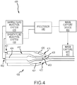
- This disclosure also describes an automated particle imaging system in which a liquid sample containing particles of interest is caused to flow through a flowcell having a viewport through which a high optical resolution imaging device captures an image.
- the high optical resolution imaging device comprises a camera such as a digital camera.
- the high optical resolution imaging device comprises an objective lens.
- the flowcell is coupled to a source of sample fluid, such as a prepared sample, and to a source of particle and/or intracellular organelle alignment liquid (PIOAL).
- a source of sample fluid such as a prepared sample
- PIOAL particle and/or intracellular organelle alignment liquid
- the system permits capture of focused images of particles in a sample in flow.
- the images can be used in automated, high throughput processes for categorizing and subcategorizing particles.
- An exemplary visual analyzer may include a processor to facilitate automated analysis of the images.
- the visual analyzer can be used in methods of this disclosure to provide automated image-based WBC differential counting or other blood sample particle analysis protocols.
- the methods of this disclosure relate to automated identification of morphological abnormalities for determining, diagnosing, prognosing, predicting, and/or supporting a diagnosis of whether a subject is healthy or has a disease, condition, abnormality and/or infection and for monitoring whether a subject is responsive or non-responsive to treatment.
- Embodiments of the present invention provide sheath fluid compositions useful for particle and/or intracellular organelle alignment in cells treated with particle contrast agent compositions. Such techniques overcome certain difficulties associated with conventional sheath fluids used in flow cytometry that may suffer from the disadvantages of maintaining cell morphology and/or not providing for the capture of optimized images which permit determination of one or more blood components.
- a viscosity difference between a ribbon-shaped sample stream and a sheath fluid and/or a thickness of the ribbon-shaped sample stream can introduce shear forces to act on the particles while in flow thereby causing the particles to align or remain in alignment throughout an imaging process in a visual analyzer.
- the sample will be contrast enhanced.
- this disclosure relates to a sheath fluid that can be used in image based analysis of particles in samples such as cells and other particle features in other biological fluids such as cerebrospinal fluid and effusions associated with particular conditions.
- Cell category and/or subcategory counts as described for use in blood samples in this disclosure as non-limiting examples of the sort of samples that may be analyzed.
- Cells present in samples may also include bacterial or fungal cells as well as white blood cells, red blood cells or platelets.
- particle suspensions obtained from tissues or aspirates may be analyzed.
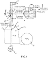
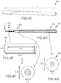
- a stream of sample fluid can be injected through a cannula with a flattened opening to establish a flowpath with a considerable width.
- the sheath fluid can be introduced into the flowcell and carries the sample fluid along through the imaging area, then toward a discharge.
- the sheath fluid has a different viscosity, e.g., higher, than the sample fluid, and, optionally, a different flow rate at the point of injection to the ribbon-shaped sample stream results in the sample fluid flattening into a thin ribbon shape.
- the thin ribbon of sample fluid is carried along with the sheath fluid, through a narrowing flowpath transition zone, to pass in front of a viewing port where a high optical resolution imaging device and a light source are arranged to view the ribbon-shaped sample stream.
- the viscosity of the sheath fluid is higher than the viscosity of the sample.
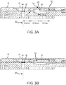
- the viscosity of the sheath fluid, the viscosity of the sample material, the flow rate of the sheath fluid and the flow rate of the sample material are coordinated, for example in combination with a ribbon compression effect provided by a narrowing transition zone, to provide the flow in a ribbon-shaped sample stream with predetermined dimensional characteristics, such as an advantageous ribbon-shaped sample stream thickness. Maintaining an advantageous ribbon-shaped sample stream thickness provides, as an example, a high percentage of in-focus cells or in-focus cellular components.
- Embodiments of the instant disclosure are based at least in part on the discovery that the addition of a suitable amount of a viscosity agent in the sheath fluid significantly improves particle/cell alignment in a flowcell, for example in a flowcell having a narrowing transition zone, and increases in-focus intracellular contents of cells, resulting in higher quality images of cells in flow compared to use of a non viscosity-modified conventional sheath fluid used in flow cytometry.
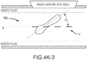
- the addition of the viscosity agent increases the shear forces on elongate or non-spherical particles or cells like red blood cells (RBCs) which then aligns the cells in a plane substantially parallel to the flow direction, which results in image optimization.
- RBCs red blood cells
- the white blood cells can be compressible or deformable in response to the shear forces conferred by the viscosity agent or differential, thus leading to particle elongation or compression and alignment under shear.
- Alignment of particles that are smaller in diameter than the flow stream may be obtained by increasing the viscosity of the sheath fluid. This results in improved alignment of those particles in a plane substantially parallel to the direction of the flow.
- the ribbon-shaped sample stream thickness can be affected by the relative viscosities and flow rates of the sample fluid and the sheath fluid, for example in combination with the geometry of the narrowing transition zone of the flowcell.
- the feed source of the sample and/or the feed source of the sheath fluid for example comprising precision displacement pumps, can be configured to provide the sample and/or the sheath fluid at stable flow rates for optimizing the dimensions of the ribbon-shaped sample stream, namely as a thin ribbon at least as wide as the field of view of the imaging device.
- An exemplary sheath fluid embodiment is used in a flowcell for particle analysis.
- a sample is enveloped in the stream of the sheath fluid and passed through the flowcell of the analyzer device. Then information from the sample when passing through the detection area is collected, enabling an analyzer to analyze particles/cells contained in the sample.
- the use of the sheath fluid on such an analyzer allows accurate categorization and subcategorization and counting of cells and/or particles contained in samples.
- sheath fluid is useful in obtaining information relating to following cells and/or particles related thereto: including for example; neutrophil, lymphocyte, monocyte, eosinophil, basophil, platelet, reticulocyte, nucleated RBC, blast, promyelocyte, myelocyte, and/or a metamyelocyte.
- the present disclosure provides novel compositions for conducting particle analysis.
- the present disclosure relates to a particle and/or intracellular organelle alignment liquid (PIOAL) used in an analyzer for analyzing particles in a sample.
- PIOAL particle and/or intracellular organelle alignment liquid
- sheath fluid and PIOAL can be used interchangeably throughout this disclosure.
- the present disclosure further describes methods for producing the PIOAL and methods for using the PIOAL to analyze particles.
- the PIOAL of this invention is useful, as an example, in methods for automated categorization and subcategorization of particles in a sample.
- the system can be configured for combined viscosity and geometric hydrofocusing.
- the particles can be included in a blood fluid sample having a sample fluid viscosity.
- Exemplary methods can include flowing a sheath fluid along a flowpath of a flowcell, and the sheath fluid can have a sheath fluid viscosity that differs from the sample fluid viscosity by a viscosity difference in a predetermined viscosity difference range.
- Methods can also include injecting the blood fluid sample into the flowing sheath fluid within the flowcell so as to provide a sample fluid stream enveloped by the sheath fluid.
- methods can include flowing the sample fluid stream and the sheath fluid through a reduction in flowpath size toward an imaging site, such that a viscosity hydrofocusing effect induced by an interaction between the sheath fluid and the sample fluid stream associated with the viscosity difference, in combination with a geometric hydrofocusing effect induced by an interaction between the sheath fluid and the sample fluid stream associated with the reduction in flowpath size, is effective to provide a target imaging state in at least some of the plurality of particles at the imaging site while a viscosity agent in the sheath fluid retains viability of cells in the sample fluid stream leaving structure and content of the cells intact when the cells extend from the sample fluid stream into the flowing sheath fluid.
- methods may include imaging the plurality of particles at the imaging site.
- the flowpath at the imaging site defines a plane that is substantially parallel to the focal plane.
- the target orientation corresponds to a target alignment relative to the focal plane at the imaging site.
- the target alignment corresponds to a target particle alignment relative to the focal plane at the imaging site.
- the target alignment corresponds to a target intraparticle structure alignment relative to the focal plane at the imaging site.
- the target orientation corresponds to a target position relative to the focal plane at the imaging site.
- the target position corresponds to a target particle position relative to a focal plane at the imaging site.
- the target position corresponds to a target intraparticle structure position relative to a focal plane at the imaging site.
- the target position is within the focal plane. In some examples, the target position is at a distance from the focal plane, the distance corresponding to a positional tolerance. In some examples, the target orientation corresponds to a target alignment relative to the focal plane and a target position relative to the focal plane. In some examples, the target imaging state corresponds to a target orientation of one or more target intraparticle structures in the flow relative to a focal plane of an imaging device used to acquire images at the imaging site. In some examples, the flowpath at the imaging site defines a plane that is substantially parallel to the focal plane. In some examples, the target orientation corresponds to a target alignment relative to the focal plane at the imaging site. In some examples, the target alignment corresponds to a target particle alignment relative to the focal plane at the imaging site.
- the target alignment corresponds to a target intraparticle structure alignment relative to the focal plane at the imaging site.
- the target orientation corresponds to a target position relative to the focal plane at the imaging site.
- the target position corresponds to a target particle position relative to a focal plane at the imaging site.
- the target position corresponds to a target intraparticle structure position relative to a focal plane at the imaging site.
- the target position is within the focal plane.
- the target position is at a distance from the focal plane, the distance corresponding to a positional tolerance.
- the target orientation corresponds to a target alignment relative to the focal plane and a target position relative to the focal plane.
- the target imaging state corresponds to a target deformation of one or more target particles or of one or more target intraparticle structures.
- the process of injecting the blood fluid sample is performed by directing a stream of the blood fluid sample through a sample injection tube with a sample fluid velocity.
- the injection tube can have a port within the flowpath.
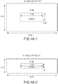
- the port can define a width, a thickness, and a flow axis extending along the flowpath. The width can be being greater than the thickness so that the sample stream has opposed major surfaces transverse to the imaging path adjacent the imaging site.
- the sheath fluid flowing along the flowpath of the flowcell extends along the major surfaces of the sample stream and has a sheath fluid velocity different than the sample fluid velocity.
- an interaction between the sheath fluid and the sample fluid associated with the differing velocities, in combination with the interaction between the sheath fluid and the sample fluid associated with the differing viscosities, provides the target imaging state.
- the plurality of particles can include a red blood cell, a white blood cell, and/or a platelet.
- the plurality of particles can include a cell having an intraparticle structure.
- An intraparticle structure can be an intracellular structure, an organelle, or a lobe.
- the sheath fluid has a viscosity between 1 and 10 centipoise (cP). In some embodiments, the predetermined viscosity difference has an absolute value within a range from about 0.1 to about 10 centipoise (cP). In some embodiments, the predetermined viscosity difference has an absolute value within a range from about 1.0 to about 9.0 centipoise (cP). In some embodiments, the predetermined viscosity difference has an absolute value within a range from about 1.0 to about 5.0 centipoise (cP). In some embodiments, predetermined viscosity difference has an absolute value of about 3.0 centipoise (cP).
- the viscosity agent of the sheath fluid includes glycerol.
- the viscosity agent of the sheath fluid includes glycerol and polyvinylpyrrolidone (PVP).
- the viscosity agent of the sheath fluid includes glycerol present at a final concentration of about 6.5 % v/v under operating conditions.
- the viscosity agent of the sheath fluid includes glycerol present at a final concentration of about 5 % (v/v) and polyvinylpyrrolidone (PVP) present at a concentration of about 1 % (w/v) under operating conditions.
- glycerol present at a final concentration of about 5 % (v/v)
- PVP polyvinylpyrrolidone
- the blood fluid sample at the imaging site has a linear velocity within a range from 20 to 200 mm/second. In some examples, the blood fluid sample at the imaging site has a linear velocity within a range from 50 to 150 mm/second. In some examples, the blood fluid sample has a sample stream thickness of up to 7 ⁇ m and a sample stream width within a range from 500 to 3000 ⁇ m at the imaging site. In some examples, the blood fluid sample has sample stream thickness within a range from 2 to 4 ⁇ m and a sample stream width within a range from 1000 to 2000 ⁇ m at the imaging site.
- the plurality of particles includes a set of non-spherical particles
- the blood fluid sample has a direction of flow at the imaging site, and more than 75 % of the set of non-spherical particles are aligned substantially in a plane parallel to the direction of flow such a major surface of each aligned non-spherical particle is parallel to the plane parallel to the direction of flow.
- the plurality of particles includes a set of non-spherical particles
- the blood fluid sample has a direction of flow at the imaging site, and at least 90% of the set of non-spherical particles are aligned within 20 degrees from a plane substantially parallel to the direction of flow.
- the plurality of particles includes intraparticle structures, the blood fluid sample has a direction of flow at the imaging site, and at least 92% of the intraparticle structures are substantially parallel to the direction of flow.
- Described herein by way of example only are systems for imaging a plurality of particles in a blood fluid sample having a sample fluid viscosity.
- the system can be configured for use with a sheath fluid having a sheath fluid viscosity that differs from the sample fluid viscosity by a viscosity difference in a predetermined viscosity difference range.
- Exemplary systems can include a flowcell having a flowpath and a sample fluid injection tube, the flowpath having a reduction in flowpath size, a sheath fluid input in fluid communication with the flowpath of the flowcell so as to transmit a flow of the sheath fluid along the flowpath of the flowcell, and a blood fluid sample input in fluid communication with the injection tube of the flowcell so as to inject a flow of the blood fluid sample into the flowing sheath fluid within the flowcell, such that as the sheath fluid and the sample fluid flow through the reduction in flowpath size and toward an imaging site, a viscosity hydrofocusing effect induced by an interaction between the sheath fluid and the sample fluid associated with the viscosity difference, in combination with a geometric hydrofocusing effect induced by an interaction between the sheath fluid and the sample fluid associated with the reduction in flowpath size, provides a target imaging state in at least some of the plurality of particles at the imaging site while a viscosity agent in the sheath fluid retains viability of cells in the sample fluid stream leaving
- the target imaging state corresponds to a target orientation of one or more target particles in the flow relative to a focal plane of an imaging device used to acquire images at the imaging site.
- the plurality of particles includes a member selected from the group consisting of a red blood cell, a white blood cell, and a platelet.
- the plurality of particles includes a cell having an intraparticle structure.
- An intracellular structure can be an intracellular structure, an organelle, or a lobe.
- the predetermined viscosity difference has an absolute value within a range from about 0.1 to about 10 centipoise (cP).
- the viscosity agent of the sheath fluid includes glycerol.
- the viscosity agent of the sheath fluid includes glycerol and polyvinylpyrrolidone (PVP).
- the plurality of particles includes a set of non-spherical particles
- the blood fluid sample has a direction of flow at the imaging site, and at least 90% of the set of non-spherical particles are aligned within 20 degrees from a plane substantially parallel to the direction of flow.
- the target orientation corresponds to a target particle orientation relative to a focal plane at the imaging site.
- a particle may be a red blood cell, a white blood cell, or a platelet.
- the target orientation corresponds to a target intraparticle structure orientation relative to a focal plane at the imaging site. (e.g. intraparticle structure can be an intracellular structure, an organelle, or a lobe).
- the flowpath at the imaging site defines a plane that is substantially parallel to the focal plane.
- the target orientation corresponds to a target alignment relative to the focal plane at the imaging site.
- the target alignment corresponds to a target particle alignment relative to a focal plane at the imaging site.
- the target alignment corresponds to a target intraparticle structure alignment relative to a focal plane at the imaging site.
- the target orientation corresponds to a target position relative to the focal plane at the imaging site.
- the target position corresponds to a target particle position relative to a focal plane at the imaging site.
- the target position corresponds to a target intraparticle structure position relative to a focal plane at the imaging site.
- the target position is within the focal plane. In some examples, the target position is at a distance from the focal plane, the distance corresponding to a positional tolerance. In some examples, the target orientation corresponds to a target alignment relative to the focal plane and a target position relative to the focal plane. In some examples, the target imaging state corresponds to a target deformation at the imaging site.
- a blood fluid sample source can be configured to provide the blood fluid sample a sample fluid velocity into the flowing sheath fluid, such that the sheath fluid has a sheath fluid velocity that is different from the sample fluid velocity.
- an interaction between the sheath fluid and the sample fluid associated with the differing velocities, in combination with the interaction between the sheath fluid and the sample fluid associated with the differing viscosities, provides the target imaging state.
- the flowpath of the flowcell includes a zone with a change in flowpath size, and an interaction between the sheath fluid and the sample fluid associated with the change in flowpath size, in combination with the interaction between the sheath fluid and the sample fluid associated with the differing viscosities, provides the target imaging state.
- the interaction between the sheath fluid and the sample fluid associated with the change in flowpath size contributes to providing the target imaging state by producing a lateral fluid compression force.
- the plurality of particles includes a red blood cell, a white blood cell, and/or a platelet.
- the plurality of particles includes a cell having an intraparticle structure, and the structure can be an intracellular structure, an organelle, or a lobe.
- the predetermined viscosity difference has an absolute value within a range from about 0.1 to about 10 centipoise (cP). In some embodiments, the predetermined viscosity difference has an absolute value within a range from about 1.0 to about 9.0 centipoise (cP). In some embodiments, the predetermined viscosity difference has an absolute value within a range from about 1.0 to about 5.0 centipoise (cP). In some embodiments, the predetermined viscosity difference has an absolute value of about 3.0 centipoise (cP).
- the sheath fluid includes a viscosity agent includes glycerol.
- the blood fluid sample at the imaging site has a linear velocity within a range from 20 to 200 mm/second. In some examples, the blood fluid sample at the imaging site has a linear velocity within a range from 50 to 150 mm/second. In some examples, the blood fluid sample has a sample stream thickness of up to 7 ⁇ m and a sample stream width of over 500 ⁇ m at the imaging site. In some examples, the blood fluid sample has a sample stream thickness within a range from 2 to 4 ⁇ m and a sample stream width within a range from 1000 to 2000 ⁇ m at the imaging site.
- the plurality of particles includes a set of non-spherical particles
- the blood fluid sample has a direction of flow at the imaging site, and at least 90% of the set of non-spherical particles are aligned and/or positioned substantially in a plane parallel to the direction of flow.
- the plurality of particles includes a set of non-spherical particles
- the blood fluid sample has a direction of flow at the imaging site, and at least 95% of the set of non-spherical particles are aligned within 20 degrees from a plane substantially parallel to the direction of flow.
- the plurality of particles include intraparticle structures, the blood fluid sample has a direction of flow at the imaging site, and at least 92% of the intraparticle structures are substantially parallel to the direction of flow.
- the present invention is drawn to a particle and intracellular organelle alignment liquid (PIOAL) for use in a combined viscosity and geometric hydrofocusing analyzer.
- PIOAL can direct flow of a blood sample fluid of a given viscosity that is injected into a narrowing flowcell transition zone of the visual analyzer so as to produce a sample fluid stream enveloped by the PIOAL.
- the PIOAL includes a fluid having a higher viscosity than the viscosity of the blood sample fluid.
- a viscosity hydrofocusing effect induced by an interaction between the PIOAL fluid and the sample fluid associated with the viscosity difference in combination with a geometric hydrofocusing effect induced by an interaction between the PIOAL fluid and the sample fluid associated with the narrowing flowcell transition zone, is effective to provide a target imaging state in at least some of the plurality of particles at an imaging site of the visual analyzer while a viscosity agent in the PIOAL retains viability of cells in the sample fluid stream leaving structure and content of the cells intact when the cells extend from the sample fluid stream into the flowing sheath fluid.
- the viscosity agent of the sheath fluid includes glycerol.
- the viscosity agent of the sheath fluid includes polyvinylpyrrolidone (PVP).
- PVP polyvinylpyrrolidone
- the PIOAL has a viscosity of between about 1-10 centipoise (cP).
- the particle and intracellular organelle alignment liquid (PIOAL) of the invention for use in a visual analyzer configured to direct flow of a sample of a given viscosity in a flow path.
- the PIOAL includes a fluid having a higher viscosity than the viscosity of the sample.
- the PIOAL can be effective to support the flow of the sample and to align particles and increase the in-focus content of particles and intracellular organelles of cells flowing in the flowpath, whereby the aligned particles and intracellular organelles of cells can be imaged.
- the PIOAL further includes a viscosity agent.
- the PIOAL further includes a buffer, a pH adjusting agent, an antimicrobial agent, an ionic strength modifier, a surfactant, and/or a chelating agent.
- the particle and intracellular organelle alignment liquid is isotonic.
- the particle and intracellular organelle alignment liquid includes sodium chloride.
- the pH of the PIOAL sample is between about 6.0 to about 8.0 under operating conditions.
- the pH of the PIOAL sample mixture is between about 6.5 to about 7.5 under operating conditions.
- the PIOAL includes a pH adjusting agent for adjusting the pH is between about 6.8 to about 7.2 under operating conditions. In some embodiments, the PIOAL liquid has a target viscosity of between about 1-10 centipoise under operating conditions.
- Embodiments of the present invention encompass a stock solution of concentrated PIOAL.
- the concentrated stock solution can be diluted to achieve the target viscosity.
- the concentration of the stock solution is present at least about 1.1x to at least about 100x concentration of the PIOAL under operating conditions.
- the viscosity agent includes glycerol.
- the viscosity agent includes glycerol and polyvinylpyrrolidone (PVP).
- Said glycerol is present at a final concentration of about 6.5 % v/v under operating conditions.
- said glycerol is present at a final concentration of about 5 % v/v and the PVP is present at a concentration of about 1 % w/v under operating conditions.
- said PVP is present at a final concentration of about 1 % w/v under operating conditions.
- kits that include a PIOAL as disclosed herein.
- Exemplary methods can include flowing a sheath fluid along a flowpath of a flowcell.
- the sheath fluid has a sheath fluid viscosity higher than the sample fluid viscosity.
- Methods can also include injecting the blood fluid sample into the flowing sheath fluid within the flowcell.
- the plurality of cells can include a first subset with major surfaces oriented transverse to an orientation of an imaging path.
- Methods can also include imaging the particles along the imaging path at an imaging site while the plurality of cells include a second subset with the major surfaces oriented transverse to the imaging path, the second subset being more numerous than the first subset.
- Methods can also include directing the fluid blood sample and the sheath fluid through a reduction in flowpath size such that an interaction between the sheath fluid and the sample fluid associated with the differing viscosities reorients at least some of the plurality of cells such that the second subset is more numerous than the first subset.
- Systems for imaging a plurality of cells in a blood fluid sample having a sample fluid viscosity can be configured for use with a sheath fluid having a sheath fluid viscosity higher than the sample fluid viscosity, the cells having opposed major surfaces.
- Exemplary systems can include a flowcell having a flowpath and a sample fluid injection tube, a sheath fluid input in fluid communication with the flowpath of the flowcell so as to transmit a flow of the sheath fluid along the flowpath of the flowcell, and a blood fluid sample input in fluid communication with the injection tube of the flowcell so as to inject a flow of the blood fluid sample into the flowing sheath fluid within the flowcell such that the plurality of the injected cells including a first subset with major surfaces aligned transverse to an orientation of an imaging path.
- the flowpath of the flowcell can have a zone with a change in flowpath size configured such that an interaction between the sheath fluid and the blood sample fluid associated with the differing viscosities reorients at least some of the particles.
- Systems can also include an imaging device that images the plurality of particles along the imaging path at an imaging site while the major surfaces of the second subset of the plurality of cells are oriented transverse to the imaging path.
- a method for imaging a particle comprising: treating particles in a sample using the particle contrast agent compositions of this disclosure; illuminating the stained particle with light in a visual analyzer comprising a flowcell and autofocus apparatus; obtaining a digitized image of the particle enveloped in a particle and/or intracellular organelle alignment liquid (PIOAL); and; analyzing a particle in the sample based on the image information.
- a visual analyzer comprising a flowcell and autofocus apparatus
- PIOAL intracellular organelle alignment liquid
- the particle is selected from at least one of neutrophil, lymphocyte, monocyte, eosinophil, basophil, platelet, reticulocyte, nucleated red blood cell (RBC), blast, promyelocyte, myelocyte, metamyelocyte, red blood cell (RBC), platelet, cell, bacteria, particulate matter, cell clump, or cellular fragment or component.
- the apparatus may be used for automated image based white blood cell (WBC) differential counting, as well as automated identification of morphological abnormalities useful in determining, diagnosing, prognosing, predicting, and/or supporting a diagnosis of whether a subject is healthy or has a disease, condition, or infection and/or is responsive or non-responsive to treatment.
- WBC white blood cell
- compositions for analyzing a sample containing particles Described herein by way of example only is an automated particle imaging system which comprises an analyzer which may be, for example, a visual analyzer.
- the visual analyzer may further comprise a processor to facilitate automated analysis of the images.
- a system comprising a visual analyzer for obtaining images of a sample comprising particles suspended in a liquid.
- the system may be useful, for example, in characterizing particles in biological fluids, such as detecting and quantifying erythrocytes, reticulocytes, nucleated red blood cells, platelets, and white blood cells, including white blood cell differential counting, categorization and subcategorization and analysis.
- biological fluids such as detecting and quantifying erythrocytes, reticulocytes, nucleated red blood cells, platelets, and white blood cells, including white blood cell differential counting, categorization and subcategorization and analysis.
- the blood fluid sample is introduced into a flowing sheath fluid, and the combined sheath and sample fluids are compressed with a narrowing flowpath transition zone that reduces the thickness of the sample ribbon fluid flow.
- particles such as cells can be oriented and/or compressed within the blood fluid sample by the surrounding viscous sheath fluid, for example in combination with a geometric focusing effect provided by a narrowing transition zone.
- internal features within blood cells can be aligned an oriented as a result of a viscosity differential between the sample fluid and the sheath fluid, for example in combination with a geometric focusing effect provided by a narrowing transition zone.
- a prepared sample stream is arranged in a thin ribbon having a stable position between opposite walls of a flowcell.
- the positioning of the sample stream and its flattening into a thin ribbon shape may be achieved by flow between layers of a PIOAL introduced into the flowcell that differs in viscosity from the sample fluid and is flowed through a symmetrical narrowing transition zone of a flow channel.
- FIG. 1 schematically shows an exemplary flowcell 22 not being part of the claimed invention, for conveying a sample fluid through a viewing zone 23 of a high optical resolution imaging device 24 in a configuration for imaging microscopic particles in a sample flow stream 32 using digital image processing.
- Flowcell 22 is coupled to a source 25 of sample fluid which may have been subjected to processing, such as contact with a particle contrast agent composition and heating.
- Flowcell 22 is also coupled to one or more sources 27 of a particle and/or intracellular organelle alignment liquid (PIOAL), such as a clear glycerol solution having a viscosity that is greater than the viscosity of the sample fluid.
- PIOAL particle and/or intracellular organelle alignment liquid
- the sample fluid is injected through a flattened opening at a distal end 28 of a sample feed tube 29, and into the interior of the flowcell 22 at a point where the PIOAL flow has been substantially established resulting in a stable and symmetric laminar flow of the PIOAL above and below (or on opposing sides of) the ribbon-shaped sample stream.
- the sample and PIOAL streams may be supplied by precision metering pumps that move the PIOAL with the injected sample fluid along a flowpath that narrows substantially.
- the PIOAL envelopes and compresses the sample fluid in the zone 21 where the flowpath narrows. Hence, the decrease in flowpath thickness at zone 21 can contribute to a geometric focusing of the sample stream 32.
- the sample fluid ribbon 32 is enveloped and carried along with the PIOAL downstream of the narrowing zone 21, passing in front of, or otherwise through the viewing zone 23 of, the high optical resolution imaging device 24 where images are collected, for example, using a CCD 48.
- Processor 18 can receive, as input, pixel data from CCD 48.
- the sample fluid ribbon flows together with the PIOAL to a discharge 33.
- the narrowing zone 21 can have a proximal flowpath portion 21a having a proximal thickness PT and a distal flowpath portion 21b having a distal thickness DT, such that distal thickness DT is less than proximal thickness PT.
- the sample fluid can therefore be injected through the distal end 28 of sample tube 29 at a location that is distal to the proximal portion 21a and proximal to the distal portion 21b.
- the sample fluid can enter the PIOAL envelope as the PIOAL stream is compressed by the zone 21.
- the digital high optical resolution imaging device 24 with objective lens 46 is directed along an optical axis that intersects the ribbon-shaped sample stream 32.
- the relative distance between the objective 46 and the flowcell 33 is variable by operation of a motor drive 54, for resolving and collecting a focused digitized image on a photosensor array.
- the system can operate to hydrofocus the sample fluid ribbon 32.
- hydrofocus or hydrofocusing can refer to a focusing effect which is influenced by a viscosity difference between the sheath and sample fluids, a geometric narrowing transition zone of the flowcell, and a velocity difference between the sheath and sample fluids. Hydrodynamic flow results from the velocity difference between the sample and sheath fluid streams, which affects the flow ribbon thickness and shape.
- flowcell 22 is further depicted in FIGS. 2 and 3 .
- flowcell 22 can be coupled with a sample source 25 and also to a source 27 of PIOAL material.
- the sample fluid is injected into the flowcell 22 via the cannula 29, for example through a distal exit port 31 of the cannula 29.
- the PIOAL sheath fluid is not in a laminar flow state as it travels through a curved channel section 41 in the flowcell from the source 27 toward the viewing zone 23.
- the flowcell 22 can be configured so that the PIOAL sheath fluid is or becomes laminar, or presents a flat velocity profile, as it flows past the distal exit port 31 where sample fluid is introduced into the flowing sheath fluid.
- the sample fluid and the PIOAL can flow along the flowcell 22 in a direction generally indicated by arrow A, and then out of the flowcell 22 via discharge 33.
- the flowcell 22 defines an internal flowpath 20 that narrows symmetrically (e.g. at transition zone 21) in the flow direction A. The symmetry of the flowpath contributes to a robust and centered flow of the sample stream.
- the flowcell 22 is configured to direct a flow 32 of the sample enveloped with the PIOAL through a viewing zone 23 in the flowcell, namely behind viewing port 57. Associated with the viewport 57 is an autofocus pattern 44.
- Flowcell 22 also has a rounded or recessed seat 58 which is configured to accept or receive a microscope objective (not shown).
- the autofocus pattern 44 can have a position that is fixed relative to the flowcell 22, and that is located at a displacement distance from the plane of the ribbon-shaped sample stream 32.
- the autofocus pattern (target 44) is applied directly to the flowcell 22 at a location that is visible in an image collected through viewport 57 by a high optical resolution imaging device (not shown).
- Flowcell 22 can be constructed from a single piece of material.
- flowcell 22 can be constructed of a first or upper section or layer 22a and a second or lower section or layer 22b.
- a glass or transparent window pane 60 is attached to or integral with the first section 22a.
- the pane 60 can define at least a portion of the sample flowpath within the flowcell.
- Light from light source 42 can travel through an aperture or passage of the autofocus pattern 44 so as to illuminate sample particles flowing within the flow stream 32.
- the thickness of pane 60 can have a value within a range from about 150 ⁇ m to about 170 ⁇ m.
- the pane 60 can define or form part of the flowpath or sheath (e.g. PIOAL) channel.
- FIG. 3A depicts aspects of a flowcell not being part of the claimed invention, where a distance between the imaging axis 355 and the distal transition zone portion 316 is about 8.24 mm. A distance between the distal transition zone portion 316 and the cannula exit port 331 is about 12.54 mm. A distance between the cannula exit port 331 and the sheath fluid entrance 301 is about 12.7 mm. A distance between the cannula exit port 331 and a proximal transition zone portion 318 is about 0.73 mm.
- FIG. 3B depicts aspects of a flowcell, not being part of the claimed invention where the cannula exit port has been moved to a more distal location relative transition zone, as compared to FIG. 3A .
- the cannula distal end is advanced into the narrowing transition zone of the flowcell, and a distance between the imaging axis 355 and the distal transition zone portion 316 is within a range from about 16 mm to about 26 mm. In some case, the distance between the imaging axis 355 and the distal transition zone portion 316 is about 21 mm.
- the flowcell internal contour (e.g. at transition zone 21) and the PIOAL and sample flow rates can be adjusted such that the sample is formed into a ribbon shaped stream 32.
- the stream can be approximately as thin as or even thinner than the particles that are enveloped in the ribbon-shaped sample stream.
- White blood cells may have a diameter around 10 ⁇ m, for example.
- the cells may be oriented when the ribbon-shaped sample stream is stretched by the sheath fluid, or PIOAL.
- the optical axis of the high optical resolution imaging device 24 is substantially normal (perpendicular) to the plane of the ribbon-shaped sample stream.
- the linear velocity of the ribbon-shaped sample stream at the point of imaging may be, for example, 20-200 mm/second. In some embodiments, the linear velocity of the ribbon-shaped sample stream may be, for example, 50-150 mm/second.
- the ribbon-shaped sample stream thickness can be affected by the relative viscosities and flow rates of the sample fluid and the PIOAL.
- the source 25 of the sample and/or the source 27 of the PIOAL for example comprising precision displacement pumps, can be configured to provide the sample and/or the PIOAL at controllable flow rates for optimizing the dimensions of the ribbon-shaped sample stream 32, namely as a thin ribbon at least as wide as the field of view of the high optical resolution imaging device 24.
- the source 27 of the PIOAL is configured to provide the PIOAL at a predetermined viscosity. That viscosity may be different than the viscosity of the sample, and can be higher than the viscosity of the sample.
- the viscosity and density of the PIOAL, the viscosity of the sample material, the flow rate of the PIOAL and the flow rate of the sample material are coordinated to maintain the ribbon-shaped sample stream at the displacement distance from the autofocus pattern, and with predetermined dimensional characteristics, such as an advantageous ribbon-shaped sample stream thickness.
- the PIOAL has a higher linear velocity than the sample and a higher viscosity than the sample, thereby stretching the sample into the flat ribbon.
- the PIOAL viscosity can be up to 10 centipoise.
- the internal flowpath of the flowcell narrows downstream of the point of injection of the ribbon-shaped sample stream into the PIOAL, to produce a ribbon-shaped sample stream thickness, for example, up to 7 ⁇ m, and/or the internal flowpath produces a ribbon-shaped sample stream width of 500 - 3,000 ⁇ m.
- the internal flowpath of the flowcell begins a narrowing transition zone upstream of the point of injection of the sample stream into the PIOAL.
- the internal flowpath narrows to produce a ribbon-shaped sample stream thickness of 2 - 4 ⁇ m in thickness, and/or the internal flowpath results in the ribbon-shaped sample stream of 2000 ⁇ m in width.
- the thickness of the stream in this case is less than the diameter of some particles, such as red blood cells in their relaxed state. Accordingly, those particles can become reoriented to face their wider a dimension to the imaging axis, which is helpful in revealing distinguishing characteristics.
- the linear velocity of the ribbon-shaped sample stream can be limited sufficiently to prevent motion blurring of the digitized image at the image exposure time of the photosensor array.
- the light source can optionally be a strobe light that is flashed to apply high incident amplitude for a brief time.
- the light source is configured to illuminate the ribbon-shaped sample stream and the autofocus pattern simultaneously.
- the field of view for imaging and for autofocus can be different, e.g., illuminated and/or imaged separately.
- a method of focusing a visual analyzer comprises focusing a high optical resolution imaging device 24, which may be a digital high optical resolution imaging device or the digital image capture device, on an autofocus pattern 44 fixed relative to a flowcell 22, wherein the autofocus pattern 44 is located at a displacement distance 52 from a ribbon-shaped sample stream 32.
- the digital high optical resolution imaging device 24 has an objective with an optical axis that intersects the ribbon-shaped sample stream 32.
- a relative distance between the objective and the flowcell 22 is varied by operation of a motor drive 54, whereas the distance along the optical axis between the high optical resolution imaging device and the point of optimal focus is known.
- the digital high optical resolution imaging device is configured to resolve and collect a digitized image on a photosensor array.
- the motor drive is operated to focus on the autofocus pattern in an autofocus process.
- the motor drive then is operated over the displacement distance, thereby focusing the high optical resolution imaging device on the ribbon-shaped sample stream.
- the method can further include forming the ribbon-shaped sample stream into a ribbon-shape.
- the ribbon shape is presented such that the optical axis of the high optical resolution imaging device is substantially perpendicular to the ribbon-shaped sample stream, namely normal to the plane of the ribbon-shaped stream.
- FIG. 4 depicts aspects of a system 400 for imaging particles in a blood fluid sample not being part of the claimed invention.
- system 400 includes a sample fluid injection system 410, a flowcell 420, and image capture device 430, and a processor 440.
- the flowcell 420 provides a flowpath 422 that transmits a flow of the sheath fluid, optionally in combination with the sample fluid.
- the sample fluid injection system 410 may include or be coupled with a cannula or tube 412.
- the sample fluid injection system 410 can be in fluid communication with the flowpath 422 (e.g.
- sample fluid entrance 402 can operate to inject sample fluid 424 through a distal exit port 413 of the cannula 412 and into a flowing sheath fluid 426 within the flowcell 420 so as to provide a sample fluid stream 428.
- the processor 440 may include or be in operative association with a storage medium having a computer application that, when executed by the processor, is configured to cause the sample fluid injection system 410 to inject sample fluid 424 into the flowing sheath fluid 426.
- sheath fluid 426 can be introduced into the flowcell 420 by a sheath fluid injection system 450 (e.g. via sheath fluid entrance 401).
- the processor 440 may include or be in operative association with a storage medium having a computer application that, when executed by the processor, is configured to cause the sheath fluid injection system 450 to inject sheath fluid 426 into the flowcell 420.
- the distal exit port 413 of cannula 412 can be positioned at a central location along the length of the narrowing transition zone 419.
- the distal exit port can be positioned more closely to the beginning (proximal portion) of the transition zone 419 or
- the distal exit port can be positioned more closely to the end (distal portion) of the transition zone 419.
- the distal exit port 413 can be positioned entirely outside of the transition zone 419, for example as depicted in FIG. 3A (where distal exit port 331 is disposed proximal to the narrowing transition zone).
- the sample fluid stream 428 has a first thickness T1 adjacent the injection tube 412.
- the flowpath 422 of the flowcell having a decrease in flowpath size such that the thickness of the sample fluid stream 428 decreases from the initial thickness T1 to a second thickness T2 adjacent an image capture site 432.
- the image capture device 430 is aligned with the image capture site 432 so as to image a first plurality of the particles from the first sample fluid at the image capture site 432 of the flowcell 420.
- the processor 440 is coupled with the sample fluid injector system 410, the image capture device 430, and optionally the sheath fluid injection system 450.
- the processor 440 is configured to terminate injection of the first sample fluid into the flowing sheath fluid 426 and begin injection of the second sample fluid into the flowing sheath fluid 426 such that sample fluid transients are initiated.
- the processor 440 may include or be in operative association with a storage medium having a computer application that, when executed by the processor, is configured to cause the sample fluid injection system 410 to inject the second sample fluid into the flowing sheath fluid 426 such that sample fluid transients are initiated.
- the processor 440 is configured to initiate capture of an image a second plurality of the particles from the second sample fluid at the image capture site 432 of the flowcell 420 after the sample fluid transients and within 4 seconds of the imaging of the first plurality the particles.
- the processor 440 may include or be in operative association with a storage medium having a computer application that, when executed by the processor, is configured to cause the image capture device 430 to initiate capture of an image a second plurality of the particles from the second sample fluid at the image capture site 432 of the flowcell 420 after the sample fluid transients and within four seconds of the imaging of the first plurality the particles.
- a system 400 for imaging a plurality of particles in a blood fluid sample 424 having a sample fluid viscosity.
- the system 400 can be used with a sheath fluid 426 having a sheath fluid viscosity that differs from the sample fluid viscosity by a viscosity difference in a predetermined viscosity difference range.
- the system 400 can include a flowcell 420 having a flowpath 422 and a sample fluid injection tube 412.
- the flowpath 422 can have a reduction in flowpath size or narrowing transition zone.
- the system 400 can include a sheath fluid input 401 in fluid communication with the flowpath 422 of the flowcell 420 so as to transmit a flow of the sheath fluid along the flowpath 422 of the flowcell 420.
- the system 400 can also include a blood fluid sample input 402 in fluid communication with the injection tube 412 of the flowcell 420 so as to inject a flow or stream 428 of the blood fluid sample into the flowing sheath fluid 428 within the flowcell 420.
- the sample fluid 424 can exit the distal exit port 423 of the cannula 412 and into an envelope of the flowing sheath fluid 426 to form a sample ribbon 428 therein.
- a viscosity hydrofocusing effect induced by an interaction between the sheath fluid 426 and the sample fluid 424 associated with the viscosity difference in combination with a geometric hydrofocusing effect induced by an interaction between the sheath fluid 426 and the sample fluid 424 associated with the reduction in flowpath size, provides a target imaging state in at least some of the plurality of particles at the imaging site 432.
- the system 400 also includes an imaging device 430 that images the plurality of particles at the imaging site 432.
- a decrease in flowpath size can be defined by opposed walls 421a, 423a of the flowpath 422a.
- the opposed walls 421a, 423a can angle radially inward along the flowpath 422a, generally symmetric about a transverse plane 451a that bisects the sample fluid stream 428a.
- the plane 451a can bisect the sample stream 428a where the sample stream has a first thickness T1, at a location where the sample stream 428a exits a distal portion 427a of the cannula or sample injection tube 412a.
- the plane 451a can bisect the sample stream 428a where the sample stream has a second thickness T2, at a location where the sample stream 428a passes the image capture site 432a.
- the first thickness T1 has a value of about 150 ⁇ m and the second thickness T2 has a value of about 2 ⁇ m.
- the compression ratio of the sample ribbon stream is 75:1.
- the first thickness T1 has a value within a range from about 50 ⁇ m to about 250 ⁇ m and the second thickness T2 has a value within a range from about 2 ⁇ m to about 10 ⁇ m.
- the distal exit port 413a of cannula 412a can be positioned at a central location along the length of the narrowing transition zone 419a. In some cases, the distal exit port can be positioned more closely to the beginning (proximal portion 415a) of the transition zone 419a. In some cases, the distal exit port can be positioned more closely to the end (distal portion 416a) of the transition zone 419a. In some cases, the distal exit port 413a can be positioned entirely outside of the transition zone 419a, for example as depicted in FIG. 3A (where distal exit port 331 is disposed proximal to the narrowing transition zone).
- the transition zone 419a can be defined by an angular transitions at the proximal (415a) and distal (416a) portions. It is also understood that the transition zone 419a can instead present smooth or curved transitions at the proximal (415a) and distal (416a) portions, similar to the smooth or curved transitions as depicted in FIGS. 1 , 3 , 3A, 3B , and 4B-2 ).
- the first thickness T1 is much larger than the size of the sample particles, and hence the particles are contained entirely within the sample ribbon stream.
- the second thickness T2 may be smaller than the size of certain sample particles, and hence those particles may extend out of the sample fluid and into surrounding sheath fluid.
- the sample ribbon stream can flow generally along the same plane as it exits the cannula and travels toward the image capture site.
- the flowcell can also provide a separation distance 430a between the distal cannula portion 427a and the image capture site 432a.
- the distal portion 427a of the sample fluid injection tube 412a can be positioned at an axial separation distance 430a from the image capture site 432a, where the axial separation distance 432a has a value of about 21 mm. In some cases, the axial separation distance 430a has a value within a range from about 16 mm to about 26 mm.
- the axial separation distance 430a between the cannula exit port and image capture site can impact the transition time for the sample fluid as the fluid travels from the exit port to the image capture site. For instance, a relatively shorter axial separation distance 430a can contribute to a shorter transition time, and a relatively longer axial separation distance 430a can contribute to a longer transition time.
- the position of the exit port at the cannula distal portion 427a relative to the flowpath transition zone 419a, or relative to the proximal portion 415a of the flowpath transition zone 419a, can also inference the transition time for the sample fluid as the fluid travels from the exit port to the image capture site.
- the sheath fluid may have a relatively slower speed at the proximal portion 415a, and a relatively faster speed at a location between the proximal portion 415a and the distal portion 416a.
- the cannula exit port at distal portion 427a is positioned at the proximal portion 415a, it will take a longer amount of time for the sample fluid to reach the image capture site, not only because the travel distance is longer, but also because the initial speed of the sample fluid after it exits the cannula distal port is slower (due to the slower sheath fluid speed). Put another way, the longer the sample fluid is present in the thicker portion (e.g. near proximal portion 415a) of the flowcell, the longer it takes the sample to reach the image capture site. Conversely, if the cannula exit port at distal portion 427a is positioned distal to the proximal portion 415a (e.g.
- the sheath fluid is accelerated as it flows through the transition zone 419a, due to the narrowing cross-sectional area of the zone 419a.
- transition time With a shorter transition time, more time is available for image collection at the image capture site. For example, as the duration of the transition time from the cannula distal tip to the imaging area decreases, it is possible to process more samples in a specific amount of time, and relatedly it is possible to obtain more images in a specific amount of time (e.g. images per minute).
- an optical objective or front lens of an imaging device can be positioned in the seat 58 of the flowcell 22. If the exit port 31 of the cannula is too close to the seat 58, then the sample fluid may not be sufficiently stabilized after it is injected into the sheath fluid so as to provide desired imaging properties at the image capture site. Similarly, it may be desirable to maintain the tapered transition region 21 at a distance from the viewing zone 23, so that the tapered region does not interfere with the positioning of the seat 58 which receives the image capture device objective.
- the downstream end 427a of the sample fluid injection tube 412a can be positioned distal to a proximal portion 415a of the flowpath transition zone 419a.
- the downstream end 427a of the sample fluid injection tube 412a can be positioned proximal to a distal portion 416a of the flowpath transition zone 419a.
- the sample fluid can be injected from the injection cannula 412a and into the flowcell at a location within the transition zone 419a.
- Symmetry in the decrease in flowpath size operates to limit particle misalignment in the blood fluid sample.
- such symmetry can be effective to limit red blood cells imaging orientation misalignment in the blood fluid sample to less than about 20%.
- Methods disclosed herein by way of example only may be operable to the flagging rate during blood count analysis to below 30%, 29%, 28%, 27%, 26%, 25%, 24%, 23%, 22%, 21%, 20%, 19%, 18%, 17%, 16%, 15%, 14%, 13%, 12%, 11%, 10%, 9%, 8%, 7%, 6% or 5% of samples.
- the image capture site 432a has a field of view 433a of between about 150 ⁇ m x 150 ⁇ m and 400 ⁇ m x 400 ⁇ m. In some examples, the image capture site 432a has a field of view 433a of about 275 ⁇ m x 275 ⁇ m. In some examples, the field of view can be defined in terms of length times width. If expressed as surface area, a 275 ⁇ m x 275 ⁇ m field of view has an area of 75,625 ⁇ m 2 .
- the field of view can be determined by the imaging device objective and its magnification. In some examples, the field of view can correspond to the extent of the field (area) that is imaged by the collection optics (e.g. objective, tube lens, and camera). In some examples, the field of view is much smaller than the viewing port of transparent area at the image capture site.
- FIGS. 4A -1 and 4A-2 illustrate the effects of hydrofocusing on the sample stream as it travels from the cannula exit port to the image capture site.
- the sample stream can have a height H(S) of about 150 ⁇ m and a width W(S) of about 1350 ⁇ m.
- the PIOAL sheath stream can have a height H(P) of about 6000 ⁇ m and a width W(P) of about 4000 ⁇ m.
- the sample stream can have a height H(S) of about 2 ⁇ m and a width W(S) of about 1350 ⁇ m.
- the PIOAL sheath stream can have a height H(P) of about 150 ⁇ m and a width W(P) of about 4000 ⁇ m.
- the cross sectional area of the PIOAL sheath stream at the cannula exit is 40 times larger than the cross sectional area near the image capture site.
- the flow of the sample and sheath fluids through the flowcell can be approximated with a parallel plate profile model.
- the flow rate in the center of the sample fluid stream e.g. as depicted in FIG. 4A -2
- the cross-sectional area of the sample flow at the cannula exit (e.g. W(S) x H(S) in FIG. 4A -1) is 40 times larger than the cross-sectional area of the sample flow at the imaging site (e.g. W(S) x H(S) in FIG. 4A -2).
- the volumetric flow rate of sheath fluid at the imaging area can be about 45 ⁇ L/second.
- the volumetric flow rate of sample fluid at the imaging area can be about 0.232 ⁇ L/second.
- the cross-sectional area of the combined sheath and sample streams at the imaging site is 600,000 ⁇ m 2 .
- the average flowstream velocity at the imaging site is 75 mm/second.
- the flow rate or velocity can be determined as the rate that results in clear and focused cellular images. Exemplary flow rates and velocities were discovered based on flow rates of the two samples that were observed to achieve certain sample flowstream ribbon shapes or characteristics at the imaging site. For example, at flow rate of about 75 mm/sec (or within a range from 20-200 mm/sec), the cells do not flow too slow such that there are overlaps of cells in consecutive images, and the cells do not flow too fast such that ghosting effects are created
- An optimal or desired linear velocity can be achieved by either changing the volumetric flow (pump rate) or the shape of cannula.
- the flow velocity of the sample stream through the image capture zone can also be related to the performance of the image capture device relative to the flowcell function. For example, if the sample stream if flowing too quickly, it may be difficult to obtain clear images of particles contained in the sample (e.g. the shutter speed of the image capture device may be too low, thus producing a blurred image). Similarly, if the sample stream is flowing too slowly, the image capture device may obtain consecutive images of the same particle (e.g. the same particle remains in the capture frame during two image captures).
- the velocity of the sample ribbon can be modulated (e.g. by adjusting any of a variety of the flowcell operational parameters) relative to the image capture rate, so that there is minimal flow between frame captures, and hence a high percentage of the sample is imaged.
- the particle analysis system and associated components can be configured so that as the sheath fluid and fluid sample flow through the flowcell, the sheath fluid can flow at a sheath fluid volumetric rate of 45 ⁇ L/s and the fluid sample can flow at a fluid sample volumetric flow rate of 0.232 ⁇ L/s (or within a range from 0.2 to 0.35 ⁇ L/s).
- the ratio of the sheath fluid flow rate to the sample fluid flow rate is about 200.
- the ratio of the sheath fluid flow rate to the sample fluid flow rate has a value within a range from about 70 to 200.
- the ratio of the sheath fluid flow rate to the sample fluid flow rate is about 193.
- the ratio of the sheath fluid flow rate to the sample fluid flow rate is about 70.
- a ratio of sheath fluid volume to fluid sample volume flowing within the flowcell can be within a range from 25:1 to 250:1.
- the system and associated components can be configured so that as sheath fluid and fluid sample flow through the flowcell 420, the sheath fluid can flow at a sheath fluid velocity of 75 mm/sec before the imaging area and the fluid sample can flow at a fluid sample velocity of 130 mm/sec before the imaging area.
- a ratio of sheath fluid volume to fluid sample volume flowing within the flowcell can be within a range from 100:1 to 200:1.
- a flowcell can have a minimum compression ratio of about 50:1 and a maximum compression ratio of about 125:1. In some examples, the minimum compression ratio can be about 30:1 or 20:1.
- This compression ratio refers to the ratio of flow stream thicknesses H(S):H(S) when comparing FIG. 4A -1 to FIG. 4A -2.
- This compression ratio can be influenced by a combination of geometric compression (e.g. the ratio of the sheath fluid thicknesses H(P):H(P) when comparing FIG. 4A -1 to FIG. 4A -2, which can also correspond generally to the dimensions of the flowcell narrowing tapered transition zone 419a shown in FIG. 4A ) and a hydrodynamic compression (e.g. also corresponding to a difference in velocity).
- the geometric compression ratio is about 40:1.
- the decrease in flowpath size, corresponding to the transition zone can be defined by a proximal flowpath portion having a proximal thickness or height, and a distal flowpath portion having a distal thickness or height that is less than the proximal thickness or height.
- the transition zone 419b of the flowpath can have a length L between a proximal portion 415b and a distal portion 416b, where the proximal portion 415b has a proximal height 417b, and the distal portion 416b has a distal height 418b.
- the shape or contour of the transition zone can be curved or smooth, and for example can be provided in the shape of an S-curve, a sigmoidal curve, or a tangent curve.
- the proximal height 417b has a value of about 6000 ⁇ m. In some cases, the proximal height 417b has a value within a range from about 3000 ⁇ m to about 8000 ⁇ m.
- the distal height 418b has a value of about 150 ⁇ m. In some examples, the distal height 418b has a value within a range from about 50 ⁇ m to about 400 ⁇ m.
- the geometry of the transition zone 419a can provide a first angle ⁇ 1 between the first flowpath boundary 403b and the bisecting transverse plane 451b, and a second angle ⁇ 2 between the second flowpath boundary 404b and the bisecting transverse plane 451b.
- angle ⁇ 1 is about 45 degrees and angle ⁇ 2 is about 45 degrees.
- angle ⁇ 1 has a value within a range from about 10 degrees to about 60 degrees.
- angle ⁇ 2 has a value within a range from about 10 degrees to about 60 degrees. According to some instances, angles ⁇ 1 and ⁇ 2 have the same value.
- angles ⁇ 1 and ⁇ 2 can be selected so as to maintain laminar flow or minimize turbulence of the sample fluid as it travels from proximal portion 415b to distal portion 416b, which in turn can enhance alignment of particles within the sample along the transverse plane 451b.
- the distal and proximal boundaries or portions of the transition zone may be curved or smooth, instead of angled.
- FIG. 4C depicts features of an exemplary cannula or sample feed tube 400c not forming part of the invention, where the cannula has a length L.
- FIG. 4D depicts a longitudinal cross-section of cannula 400d. As shown here, the cannula 400d includes a distal flattened section 410d, a central tapered section 420d, and a proximal tubular portion 430d. As depicted in FIG. 4C -1, an exemplary cannula or sample feed tube 400c-1 can have a distal portion 410c-1 and a proximal portion 430c-1.
- the distal portion 410c-1 has a length of about 1.359 mm and a width of about 1.43 mm.
- the exit port of the distal end has an exit width W(E) of about 1.359 mm.
- a cannula may have an internal flowpath geometry that is different from what is depicted in FIGS. 4C and 4D .
- the cannula 400d-1 does not include a tapered central section having an expanded flow area cross-section. As depicted in FIG.
- cannula 400d-1 has a distal section 410d-1, a central tapered section 420d-1 having a tapering inner diameter, and a proximal section 430d-1.
- the cross-sectional inner area of 410d-1 is smaller than the cross-sectional inner area of 430d-1.
- a hematology system can process a blood sample having a volume of about 150 ⁇ L.
- the aspirated blood volume can be about 120-150 ⁇ L.
- the minimum available blood volume in the sample tube is about 500 ⁇ L for an automatic sampling mode and about 250 ⁇ L for manual sampling mode.
- the cannula or injection tube 400d shown in FIG. 4D has an internal volume of about 13 uL. According to some examples, the cannula or injection tube has an internal volume of less than about 30 uL.
- FIG. 4E illustrates a transverse cross-section of a distal flattened section 410e, not being part of the claimed invention.
- the distal section 410e has an inner width W(I) and an inner height H(I), through which a sample stream flows.
- the distal section 410e has an outer width W(O) and an outer height H(O).
- the distal portion 410e of the sample fluid injection tube has an outlet port P having a height H(I) and a width W(I), where the height H(I) is less than the width W(I).
- the height H(I) of the outlet port P of distal portion 410e (or the inner height of the distal portion 410d) can have a value of about 150 ⁇ m. In some cases, the height H(I) can be within a range from about 50 ⁇ m to about 250 ⁇ m.
- the width W(I) of the outlet port P of distal portion 410e (or the inner width of the distal portion 410d) can have a value of about 1350 ⁇ m. In some examples, the width is about 1194 ⁇ m. In some examples, the width W(I) can have a value within a range from about 500 ⁇ m to about 3000 ⁇ m. In some examples, distal flattened section 410d can be manufactured by applying a clamping force to a tube or conduit.
- FIG. 4F illustrates a transverse cross-section of a central tapered section 420f, not being part of the claimed invention.
- the central tapered section 420f has an inner diameter D(I) through which a sample stream flows.
- the central tapered section 420f has an outer diameter D(O).
- FIG. 4G illustrates a transverse cross-section of a proximal section 430g.
- the proximal section 430g has an inner diameter D(I) through which a sample stream flows.
- the distal section 430g has an outer diameter D(O).
- the injection tube or cannula 400d can have a proximal portion 430d having a first flow cross-section area (e.g. ⁇ ⁇ (D/2) 2 shown in FIG. 4G ), a distal portion 410d having a second flow cross-section area (e.g. W(I) ⁇ H(I) shown in FIG. 4E ) that is less than the first flow cross-section area, and a third portion 420d disposed between the proximal portion 430d and the distal portion 410d.
- the third portion 420d can have a third flow cross-section (e.g. ⁇ ⁇ (D/2) 2 shown in FIG.
- the outer diameter D(O) of proximal portion 430g is about 1067 ⁇ m and the inner diameter D(I) of proximal portion 430g is about 813 ⁇ m.
- FIG. 4H depicts results obtained using a stain formulation that does not include glutaraldehyde. It was observed that the cells fell apart as a result of shear forces encountered in the flowcell. Although a good stain of the nucleus was achieved, the nucleus itself appeared deformed, and the cell membrane appeared damaged. In sum, when imaged the cell appeared to be destroyed due to disruption to the cellular content and structure.
- FIG. 4H depicts WBC results obtained using a stain formulation that includes glutaraldehyde. As shown here, the cell membranes are intact and the cells are round. Hence, it was observed that the version of the stain which did not use glutaraldehyde (e.g. shown in FIG. 4H , upper panel) resulted in resulting in weakened WBC's. Although the WBC's are more intact in FIG. 4H (lower panel) the nucleus portions are damaged.
- the sheath fluid (PIOAL) used to obtain the FIG. 4H (lower panel) images included 30% glycerol.
- the sheath fluid (PIOAL) used to obtain the FIG. 4I (upper panel) images included 6.5% glycerol.
- the lower concentration of glycerol resulted in a better morphology, with the nucleus mostly unchanged. Hence, it was observed that the cell membrane in FIG. 4I (upper panel) is even more intact that than the cell membrane in FIG. 4H (lower panel).
- the lower glycerol concentration in FIG. 4I (upper panel) can operate to reduce the viscosity difference, thereby reducing the shear force. If excessive shear force is present, the force can destroy the cell membranes.
- the glycerol may have some properties that are incompatible with the cells and thus a higher concentration of glycerol may also destroy the cell membranes. Hence, it is possible to conclude that the damage to the nucleus depicted in FIG. 4H (upper panel) can be the result of the 30% glycerol in the sheath fluid.
- FIG. 4I depicts results obtained using a PIOAL with 5% glycerol and 1% PVP.
- the viscosity agent in the sheath fluid retains viability of cells in the sample fluid stream, leaving structure and content of the cells intact, for example when cells flow through the flowcell and are exposed to the flowing sheath fluid.
- the concentration percentage of glycerol is expressed in terms of (v/v) and the concentration percentage of PVP is expressed in terms of (w/v).
- FIG. 4J depicts image capture results based on a traditional microscope wet mount technique (left column) as compared to a flowcell technique (right column).
- the wet mount procedure can be considered as a target standard for image clarity and quality. It was observed that techniques involving sheath fluids and flow cell designed as disclosed herein were effective in achieving image clarity and quality equivalent to that of the wet mount procedure.
- a flowstream ribbon can split when the viscosity differential between the sample fluid and the sheath fluid exceeds a certain threshold.
- a flowstream ribbon split was observed when using a sheath fluid containing glycerol at 60%.
- a sample stream ribbon R flowing through an image capture site 432k of a flowcell 420k can have a thickness T of about 2 ⁇ m.
- thickness T of the sample stream ribbon can be up to about 3 ⁇ m.
- cells or particles that are smaller than the sample stream thickness will be contained within the ribbon.
- An exemplary red blood cell (RBC) can be present as a biconcave disk and can have a diameter D of between about 6.2 ⁇ m and about 8.2 ⁇ m.
- an exemplary red blood cell can have a maximum thickness T1 of between about 2 ⁇ m and about 2.5 ⁇ m and a minimum thickness T2 of between about 0.8 ⁇ m and about 1 ⁇ m.
- red blood cells can have a thickness of up to about 3 ⁇ m.
- Exemplary human platelets can vary in size, and can also have a thickness or diameter of about 2 ⁇ m.
- the flowcell can define a flow path thickness H having a value of about 150 ⁇ m, at the image capture site.
- the flowpath thickness F has a value between 50 ⁇ m and 400 ⁇ m. This flowpath thickness F can also correspond to the distal height 418b of distal portion 461b depicted in FIGS. 4B-1 and 4B-2 .
- the ratio of the thickness T of the sample fluid stream to the thickness of the particle (red blood cell) is about 1:1.
- a ratio of the thickness T of the sample fluid stream at the image capture site to a size of one of the particles is within a range from 0.25 to 25.
- the thickness T can have a value within a range from 0.5 ⁇ m to 5 ⁇ m.
- a viscosity differential between the sheath fluid and the sample fluid can be selected so as to achieve a desired positioning of the ribbon sample stream within the flowcell.
- Viscosity differences between fluid of the sample ribbon R and the sheath fluid can operate to align or orient particles in the sample stream, for example red blood cells, along the direction of the flow.
- the imaging device or camera can obtain images of the red blood cells such they appear round, because the major surface of the blood cell is facing toward the camera.
- the red blood cell assumes an alignment that presents a low resistance relative to the flow.
- the relative viscosity characteristics of the sheath fluid and the sample fluid can contribute to a high percentage or number of red blood cells facing toward the camera, thus enhancing the evaluation capability of the particle analysis system.
- the viscosity characteristics of the sheath fluid operate to limit particle misalignment in the blood fluid sample.
- viscosity differentials can be effective to limit red blood cells imaging orientation misalignment in the blood fluid sample to less than about 10%. That is, 90 or more red blood cells out of 100 red blood cells in a sample can be aligned so that their major surfaces face toward the imaging device.
- a symmetrical narrowing transition zone can provide a value of 20%.
- a viscous sheath fluid can reduce the percentage of misaligned cells.
- alignment effects are also observed as a result of a bilateral tapered transition zone. In some cases, it is observed that a bilateral (i.e. symmetrical) tapered transition zone is twice as effective at aligning particles as compared to an asymmetric tapered transition zone design.
- the shape of the imaged red blood cells can be used to determine whether a patient from whom the sample is obtained has a particular physiological condition or disease. For example, patients with sickle cell disease present with blood cells having an abnormal shape (i.e. in the shape of a sickle). Hence, by obtaining high quality images of aligned red blood cells, it is possible to ensure an accurate diagnosis.
- Other shape variations in red blood cells for example red blood cells having thin peripheral area and a large flat central area, whereby the red blood cell appears to have the profile of a bicycle tire, can effectively be imaged using the instant alignment techniques.
- red blood cells having a small central portion, and a thick peripheral area, whereby the red blood cell appears to have the profile of a truck tire can be imaged for diagnostic purposes.
- the improved imaging techniques disclosed herein are also useful for evaluating other red blood cell characteristics, such as hemoglobin content, iron content, and the like.
- a viscosity differential between the viscosity of the sheath fluid and the viscosity of the sample fluid produces a modified parabolic profile, wherein the profile is generally parabolic and has a central bump corresponding to a center area of the flow where the acceleration is increased, and the central bump contributes to alignment of sample particles or intraparticle organelles.
- the velocity difference between the sheath and sample ribbon and the viscosity difference generate shear forces to increase alignment of the organelles or intracellular particles. Exemplary aspects of the sheath fluid parabolic profile are discussed in US 20140315238 .
- White blood cells are typically larger than red blood cells and platelets.
- exemplary neutrophils and eosinophils can have a diameter of between about 10 ⁇ m and about 12 ⁇ m.
- Exemplary basophils can have a diameter of between about 12 ⁇ m and about 15 ⁇ m.
- Exemplary lymphocytes (small) can have a diameter of between about 7 ⁇ m and about 8 ⁇ m, and exemplary lymphocytes (large) can have a diameter of between about 12 ⁇ m and about 15 ⁇ m.
- Exemplary monocytes can have a diameter of between about 12 ⁇ m and about 20 ⁇ m.
- the configuration of the particle analysis system can operate to compress white blood cells as they travel through the image capture site 4321, as indicated in FIG. 4L .
- a central portion of the white blood cell (WBC) can be positioned within the sample fluid ribbon R, and peripheral portions of the white blood cell can be positioned within the sheath fluid.
- WBC white blood cell
- the sides of the white blood cell can extend into the sheath fluid.
- Viscosity differences between the sheath fluid and the sample fluid can operate to align organelles or other intracellular features which are present within cells such as white blood cells. Without being bound by any particular theory, it is believed that shear forces associated with the viscosity differential between the sheath fluid and the sample fluid may act upon the white blood cells so as to align the intracellular features. In some cases, shear forces associated with velocity differentials between the sheath fluid and sample fluid may contribute to such alignment. These alignment effects may be impacted by a size differential between the particles and the sample fluid ribbon as well. For example, where portions of the particles extend out of the sample fluid ribbon and into the surrounding sheath fluid, shear forces associated with the difference in viscosity may have a pronounced effect on the intracellular feature alignment.
- portions of a cell such as a white blood cell can extend into the sheath fluid.
- Embodiments of the present invention encompass sheath fluid compositions that do not lyse or shred the cell, or otherwise compromise the integrity of the outer cell membrane, when the cell is exposed to the sheath fluid.
- the viscosity agent in the sheath fluid operates to retain viability of cells in the sample fluid stream, so as to leave the structure (e.g. shape) and the content (e.g. nucleus) of the cells intact when the cell membrane or wall traverses an interface between the sample fluid ribbon and the sheath fluid envelope or otherwise extends from the sample fluid stream into the flowing sheath fluid.
- the cells may come into contact with the sheath fluid while the cells are in a compressed state or are otherwise subject to compressive forces as a result of a narrowing transition zone.
- the viscosity agent of the sheath fluid can operate to protect the compressed cells from being shredded or destroyed when they emerge from the thin sample fluid ribbon and become exposed to the viscous sheath fluid, at least until the cells reach the image capture site.
- the viscosity agent composition of the sheath fluid can operate as a cellular protectorant, while also enhancing alignment of the particles or intraparticle content.
- portions of the cell or particle may extend out of the thin sample fluid ribbon R and into the surrounding sheath fluid.
- the sheath fluid may contain cellular protectants that inhibit or prevent the sheath fluid from disrupting or lysing the cells or particles.
- the sheath fluid may contain cellular protectants that preserve the structural integrity of the cells walls as the cells are exposed to the chemical environment of the sheath fluid.
- the cellular protectants may also operate to preserve the structural integrity of the cells walls as the cells experience any shear forces induced by flowcell geometry, and a difference in velocity and/or viscosity between the sample fluid and the sheath fluid.
- the protectorants can protect the cells or particles from forces resulting from the difference in velocity between the sample fluid and sheath fluid. In this way, the cells retain their viability as they reach the image capture site.
- FIG. 4L -1 depicts exemplary aspects of parabolic flow profiles 4001-1a and 4001-1b.
- the parabolic profile 4001-1a in the upper panel is a typical velocity profile found in flows within certain flowcells (e.g. where there is little or no viscosity differential between a sample fluid flowstream that is enveloped within a sheath fluid flowstream). As can be seen, a highest linear velocity is observed in the middle of the fluid stream and slower linear velocities are observed near the flowcell wall.
- Profile 4001-1a can also be observed in fluid stream with a slight viscosity difference between the sheath and sample fluids.
- a central bump is observed as shown in profile 4001-1b, where there is a localized central area with amplified linear velocities. Particles that are sufficiently large in size will be subjected to some amount of shear force, even where such particles are fully contained within a single fluid phase (i.e. either within the sheath fluid envelope or alternatively within the sample fluid ribbon).
- the velocity of the sheath fluid may be different from the velocity of the sample fluid.
- the sheath fluid may be traveling at 80 mm/second and the sample fluid may be traveling at 60 mm/second.
- the sample fluid exits the distal cannula port at a sample fluid speed that is slower than the sheath fluid speed of the surrounding envelope.
- the sheath fluid can operate to drag the sample fluid along the flowpath of the cannula, thus accelerating the sample fluid and reducing the thickness of the sample fluid ribbon.
- the sample fluid ribbon maintains the overall volume and mass, so as it travels faster it becomes thinner.
- both the sheath fluid and the sample fluid have a velocity of between about 20 and 200 mm/second at the image capture site.
- the velocity of the sample fluid increases as the sample fluid travels from the cannula exit port to the image capture site.
- the velocity of the sample fluid at the image capture site is 40 times the velocity of the sample fluid as it exits the cannula port at the cannula distal portion.
- the decrease in cross sectional area of the sample ribbon is linear to the increase in velocity. According to some examples, if the sheath velocity at the cannula exit is higher than the sample ribbon velocity this will also increase the final sample ribbon velocity at the imaging area.
- the sheath fluid can operate to apply significant shear forces on the sample fluid ribbon and on particles within the sample fluid ribbon. Some forces are parallel to the direction of flow, and particles may also encounter forces which are perpendicular to the direction of flow. Often, as the sheath fluid and sample fluid approach the image capture site or zone, the sheath and sample fluids are traveling at or near the same velocity. Hence, the boundary or interface between the sheath and sample fluids as they pass the image capture site may present lower shear forces, as compared to the boundary or interface at the distal cannula exit port or at the tapered transition zone.
- the boundary or interface between the sheath fluid envelope and sample fluid ribbon can be in transition, such that the sample ribbon which is initially slower and thicker becomes faster and thinner, and particles in the sample fluid become more aligned.
- the shear forces may be prominent at the tapered transition zone, and can dissipate toward the image capture site.
- the shear forces at the image capture site can be represented by a parabolic profile, and can be much lower than the shear forces at the tapered transition zone.
- cells or particles can experience higher shear forces as they pass through the transition zone, and lower shear forces as they pass through the image capture site.
- the viscosity difference between the sheath and sample fluids can bring the red blood cells into alignment and thereby into focus.
- the viscosity difference between the sheath and sample fluids can bring white blood cell organelles into alignment and thereby into focus.
- enhanced imaging results can be obtained for cellular and organelle components that are aligned and brought into focus, resulting from the geometric narrowing of the stream and the velocity difference between the sheath and sample fluids.
- a viscosity hydrofocusing effect induced by an interaction between the sheath fluid and the sample fluid R associated with a viscosity difference between the sheath fluid viscosity and the sample fluid viscosity in combination with a geometric hydrofocusing effect induced by an interaction between the sheath fluid and the sample fluid R associated with the reduction in flowpath size or transition zone, provides a target imaging state in at least some of the plurality of particles at the imaging site 432k or 4321.
- the target imaging state is a target orientation relative to a focal plane F at the imaging site.
- the particle RBC
- the particle can be displaced at a distance from the focal plane F.
- the target orientation involves a target particle orientation relative to the focal plane F at the imaging site 432k-1.
- the particle can be a blood cell, such as a red blood cell, a white blood cell, or a platelet.
- the flowpath at the imaging site 432k-1 can define a P plane that is substantially parallel to or coplanar with the focal plane F.
- a portion of the particle may be positioned along the focal plane F, yet the central portion of the particle may otherwise be offset from the focal plane F.
- the target orientation involves a target position relative to the focal plane F at the imaging site 432k-1.
- the target position may involve positioning of the particle so that at least a portion of the particle is disposed along the focal plane F.
- the target position may involve positioning of the particle so that a distance between the particle and the focal plane F does not exceed a certain threshold.
- the target position involves a target particle position that is relative to the focal plane F at the imaging site 432k-1.
- the target position is at or less than a distance D from the focal plane F, where distance D corresponds to a positional tolerance.
- a viscosity differential between the sheath fluid and the sample fluid can be selected so as to achieve a desired positioning of the ribbon sample stream within the flowcell (e.g. relative to flowpath plane P and/or focal plane F).
- the viscosity differential can be selected so as to achieve a target particle position that is at or less than the positional tolerance D.
- the focal plane F has a thickness or depth of field as indicated in FIG. 4K -2
- the particle (RBC) has a target imaging state relative to the focal plane thickness.
- the target position for the particle can be within the focal plane F or at least partially within the focal plane F.
- a high optical resolution imaging device or camera can have a depth of field or focal plane thickness of about 7 ⁇ m.
- the depth of field or focal plane thickness has a value with a range from about 2 ⁇ m to about 10 ⁇ m.
- the depth of the field of the camera is similar or equal to the sample ribbon thickness at the image capture site.
- the target orientation can involve a target alignment relative to the focal plane F at the imaging site.
- the target alignment can indicate that a plane defined by the particle is aligned with the focal plane F, not to exceed a certain angle ⁇ relative to the focal plane F at the image capture site 432k-3 as shown in FIG. 4K -3.
- the target imaging state can involve a limitation on the number or percentage of misaligned particles in a sample. For example, a difference in viscosity between the sheath fluid and the sample fluid R can be effective to limit red blood cells imaging orientation misalignment in the blood fluid sample to less than about 10%.
- 90 or more red blood cells out of 100 red blood cells in a sample can be aligned so that their major surfaces face toward the imaging device (as depicted in FIGS. 4K -1 and 4K-2) or so that the alignment of those 90 or more RBCs is within 20 degrees from a plane substantially parallel to the direction of flow (e.g. RBC alignment angle ⁇ is 20 degrees or less).
- RBC alignment angle ⁇ is 20 degrees or less.
- at least 92% of non-spherical particles such as RBCs can be aligned in a plane substantially parallel to the direction of flow.
- At least between 75% and 95% of non-spherical particles such as RBCs can be substantially aligned, namely within 20 degrees from a plane substantially parallel to the direction of flow (e.g. alignment angle ⁇ is 20 degrees or less).
- 90% or more of certain particles e.g. red blood cells and/or platelets
- the present invention provides a sheath fluid or particle and intracellular organelle alignment liquid (PIOAL) for use in a combined viscosity and geometric hydrofocusing visual analyzer.
- the PIOAL can operate to direct or facilitate flow of a blood sample fluid of a given viscosity through a narrowing flowcell transition zone of the visual analyzer.
- the PIOAL includes a fluid having a higher viscosity than the viscosity of the sample.
- a viscosity hydrofocusing effect induced by an interaction between the PIOAL fluid and the sample fluid associated with the viscosity difference in combination with a geometric hydrofocusing effect induced by an interaction between the PIOAL fluid and the sample fluid associated with the narrowing flowcell transition zone, can be effective to provide a target imaging state in at least some of the plurality of particles at an imaging site of the visual analyzer while retaining viability of cells in the blood sample fluid.
- FIG. 4M depicts an exemplary neutrophil 400m (a type of white blood cell) having internal organelles such as lobes 410m.
- the internal organelles can align within the cell, as indicated by FIG. 4N .
- the intracellular organelles can be effectively imaged with an image capture device 430m, without the organelles overlapping one another. That is, instead of the lobes being stacked upon one another as depicted in FIG. 4M , when viewed from the imaging or optical axis of the image capture device the lobes are aligned and sitting side by side as depicted in FIG. 4N .
- the internal organelle alignment is a surprising and unexpected result of the viscosity differential between the sample and sheath fluids. Accordingly, enhanced imaging results corresponding to cell alignment and in-focus are achieved using the viscosity differential, hydrodynamic flow, and geometric compression features.
- a viscosity hydrofocusing effect induced by an interaction between the sheath fluid and the sample fluid R associated with a viscosity difference between the sheath fluid viscosity and the sample fluid viscosity in combination with a geometric hydrofocusing effect induced by an interaction between the sheath fluid and the sample fluid R associated with the reduction in flowpath size or transition zone, provides a target imaging state in at least some of the plurality of particles at the imaging site.
- the target imaging state may correspond to a distribution of imaging states.
- the target imaging state can involve a target intraparticle structure orientation (e.g. alignment and/or position) relative to a focal plane at the imaging site.
- a target intraparticle structure orientation e.g. alignment and/or position
- the internal structures 410m e.g. intracellular structure, organelle, lobe, or the like
- the target alignment involves a target intraparticle structure alignment relative to a focal plane F at the imaging site, similar to the particle alignment relationship depicted in FIG. 4K -3.
- the target position involves a target intraparticle structure position relative to a focal plane at the imaging site, similar to the particle position relationship depicted in FIG. 4K -1.
- the target orientation of the intraparticle structure can include both a target alignment relative to the focal plane and also a target position relative to the focal plane.
- the target imaging state can involve a target deformation at the imaging site.
- the particle 400m has a compressed shape as compared to the particle shape depicted in FIG. 4M .
- the intraparticle features can be positionally or directionally oriented (e.g. aligned with respect to the focal plane F and/or ribbon flow plane) as the particle itself is compressed in shape.
- a velocity difference between the sheath and sample fluids can produce friction within the flowstream, and a viscosity difference between the sheath and sample fluids can amplify that hydrodynamic friction.
- image analysis can involve determining certain cell or particle parameters, or measuring, detecting, or evaluating certain cell or particle features.
- image analysis can involve evaluating cell or particle size, cell nucleus features, cell cytoplasm features, intracellular organelle features, and the like.
- analysis techniques can encompass certain counting or classification methods or diagnostic tests, including white blood cell (WBC) differentials.
- WBC white blood cell
- images obtained using the flowcell can support a 5-part WBC differential test.
- images obtained using the flowcell can support a 9-part WBC differential test.
- the processor 440 can include or be in operative association with a storage medium having a computer application that, when executed by the processor, is configured to cause the system 400 to differentiate different types of cells based on images obtained from the image capture device.
- diagnostic or testing techniques can be used to differentiate various cells (e.g. neutrophils, lymphocytes, monocytes, eosinophils, basophils, metamyelocytes, myelocytes, promyelocytes, and blasts).
- PIOAL for aligning particles and repositioning intracellular content as disclosed herein.
- This is useful for image-based analysis and differential categorization and subcategorization of particles in body fluid (e.g. blood) samples.
- body fluid e.g. blood
- the methods disclosed herein by way of example only can optionally stain and/or lyse particles in a suitable manner to achieve white cell staining, reticulocyte staining and platelet staining, that mimic's Wright stained cells seen on a whole blood smear.
- the exemplary method can employ the use of a surfactant in combination with heat to achieve red cell lysis.
- aspects and embodiments of the present disclosure are based on the surprising and unexpected discovery that certain PIOAL compositions have unexpected properties aligning cells and re-positioning intracellular structures when used to perform image-based particle/cell analysis.
- FIG. 4O shows a comparison of images obtained using PIOAL versus images obtained using a non PIOAL sheath fluid.
- Use of the PIOAL resulted in more in-focus cellular contents such as lobes, cytoplasm, and/or granule.
- a PIOAL comprising a viscosity agent (about 30% glycerol) was used to process the sample.
- the pH was adjusted to a pH of about 6.8 to 7.2 and the sample mixture was made isotonic by (0.9 % sodium chloride).
- the results shown here demonstrate the efficacy of an exemplary PIOAL used on an image analyzer to align cells and intracellular organelles.
- FIGS. 4P and 4Q show a comparison of images obtained using a standard sheath fluid (FIG. P upper and lower panels) versus images obtained using an exemplary PIOAL fluid ( FIG. 4Q upper and lower panels).
- the use of PIOAL resulted in an improved RBC alignment, for example by orienting the major surfaces of the red blood cells to face toward the camera or imaging device.
- the sample was analyzed using an instrument focusing protocol (on an exemplary target 44 as depicted in FIG. 1 ) and the target was brought into focus by a visual analyzer.
- the focusing system was then offset by displacement distance 52, resulting in the particles in the ribbon-shaped sample stream being in focus.
- the blood sample was previously diluted using a sample diluent.
- the sample flowed through a cannula and along a flowpath of a flowcell, thereby generating a ribbon-shaped sample stream (e.g. 2 microns in thickness) which was between two layers of PIOAL or standard sheath (in controls).
- the visual analyzer then generates focused images of the particles in the ribbon-shaped sample stream (e.g. at about 60 frames per second) to be used for analysis.
- the blood sample is obtained from a subject and processed for analysis by the blood analyzer. Images of RBCs in a flowcell are captured while the sample is processed using a standard sheath fluid or a PIOAL. Relative percentages demonstrate significant improvement in the number of aligned RBCs based on imaging data (e.g. 4P and 4Q). The result demonstrated that PIOAL was efficacious at increasing the percentage of RBC alignment while in flow in the ribbon-shaped sample stream using the focusing instrument/protocols as described herein.
- the chart in FIG. 4R shows the percentage of non-aligned cells obtained using 0% - 30% glycerol in the PIOAL with symmetric vs. asymmetric flow cells.
- 30% glycerol in the PIOAL and a symmetric flowcell results in reducing the percentage of misaligned cells to only 8%.
- the percentage of misaligned cells increased to 87%.
- this chart demonstrates the effect of glycerol percentage and flowcell geometry on particle (e.g. RBC) alignment.
- the addition of glycerol decreases the percentage of misaligned RBC cells using either symmetric or asymmetric flowcell geometry.
- the % non-aligned RBCs was reduced from 87 % down to 15 % in the asymmetric and 46% to 8% in symmetrical cells.
- the chart provides a comparison between misalignment results (8%) obtained from an analyzer configuration that involves a symmetrical narrowing flowcell transition zone and a viscous sheath fluid and misalignment results (46%) obtained from an analyzer configuration that involves a symmetrical narrowing flowcell transition zone without the use of a viscous sheath fluid.
- the PIOAL comprises a diluent and at least one viscosity modifying agent.
- Exemplary PIOAL formulation A not being part of the invention includes a 30% (v/v) glycerol solution having 300mL glycerol and QS (quantity sufficient or to bring the final volume up to) to 1L with diluent containing 9.84g sodium sulfate, 4.07g sodium chloride, 0.11g Procaine HCl, 0.68g potassium phosphate monobasic, 0.71g sodium phosphate dibasic, and 1.86g disodium EDTA.
- the initial mixture was followed by QS to 1L with deionized water while adjusting pH to 7.2 with sodium hydroxide.
- exemplary PIOAL formulation B includes a 6.5% (v/v) glycerol solution having 65mL glycerol and QS to 1L with suitable exemplary diluent containing 9.84g sodium sulfate, 4.07g sodium chloride, 0.11g Procaine HCl, 0.68g potassium phosphate monobasic, 0.71g sodium phosphate dibasic, and 1.86g disodium EDTA.
- suitable exemplary diluent containing 9.84g sodium sulfate, 4.07g sodium chloride, 0.11g Procaine HCl, 0.68g potassium phosphate monobasic, 0.71g sodium phosphate dibasic, and 1.86g disodium EDTA.
- the initial mixture was followed by QS to 1L with deionized water while adjusting pH to 7.2 with sodium hydroxide.
- exemplary PIOAL formulation C includes a 5% glycerol (v/v) solution with 1% PVP (w/v) in buffer having 50mL glycerol, 10g PVP (MW: 360,000), 1 packet of Sigma PBS powder, at pH 7.4 (0.01M phosphate buffered saline; 0.138M sodium chloride; 0.0027M potassium chloride), and QS to 1L with deionized water.
- FIGS. 5A and 5B depict exemplary flowstream characteristics related to shear force, lateral compression, orientation, differential viscosity, relative movement between sheath and sample fluids, and the like.
- FIG. 6 depicts aspects of an exemplary method 600, by way of example only, for imaging a plurality of particles using a particle analysis system configured for combined viscosity and geometric hydrofocusing using a sheath fluid according to embodiments of the present invention.
- the particles can be included in a blood fluid sample 610 having a sample fluid viscosity.
- the method can include flowing a sheath fluid 620 along a flowpath of a flowcell as indicated by step 630.
- the sheath fluid 620 can have a sheath fluid viscosity that differs from the sample fluid viscosity by a viscosity difference in a predetermined viscosity difference range.
- the method can also include injecting the blood fluid sample 610 into the flowing sheath fluid within the flowcell, as indicated by step 630, so as to provide a sample fluid stream enveloped by the sheath fluid. Further, the methods can include flowing the sample fluid stream and the sheath fluid through a reduction in flowpath size toward an imaging site as indicated by step 640.
- a viscosity hydrofocusing effect induced by an interaction between the sheath fluid and the sample fluid stream associated with the viscosity difference is effective to provide a target imaging state in at least some of the plurality of particles at the imaging site while a viscosity agent in the sheath fluid retains viability of cells in the sample fluid stream leaving structure and content of the cells intact when the cells extend from the sample fluid stream into the flowing sheath fluid as depicted by step 670.
- Methods may also include imaging the plurality of particles at the imaging site, as depicted by step 680.
- FIGS. 7 and 8 depict aspects of shear strain rate values for certain flow conditions in a flowcell not being part of the claimed invention.
- a 30% glycerol sheath fluid is used.
- the viscosity can have a value of 2.45 x 10 -3 .
- a shear stress value can be equal to the product obtained by multiplying a viscosity value with a strain rate value.
- the sample can have a flow rate of 0.3 ⁇ L/sec and the sheath fluid can have a flow rate of 21 ⁇ L/sec.
- the sample can have a flow rate of 1 ⁇ L/sec and the sheath fluid can have a flow rate of 70 ⁇ L/sec.
- the flow presents a lower strain value toward the center (C) and a higher strain value toward the periphery (P).
- Such strain values can correspond to an asymmetric flowcell configuration, in some examples.
- the lower strain rate toward the center (C) portion of the flowstream can have a value of about 500 (1/s) or lower and the higher strain rate toward the periphery (P) of the flowstream can have a value of about 3000 (1/s) or higher.
- the lower strain rate toward the center (C) portion of the flowstream can have a value of about 1000 (1/s) or lower and the higher strain rate toward the periphery (P) of the flowstream can have a value of about 9000 (1/s) or higher.
- sample and sheath fluid rates correspond to lower strain rates
- higher sample and sheath fluid rates correspond to higher strain rates.
- the PIOAL has a suitable viscosity and density, and flow rates at the point of introduction to the flowcell of the sample are such that the sample fluid flattens into a thin ribbon.
- the ribbon-shaped sample stream is carried along with the PIOAL, to pass in front of a viewing port where an objective lens and a light source are arranged to permit viewing of the ribbon-shaped sample stream.
- the sample fluid is introduced, for example, injected at a point where the flowpath of the PIOAL narrows symmetrically. As a result, the sample fluid stream is flattened and stretched into a thin ribbon.
- a PIOAL of this disclosure may be used as the sheath fluid with any visual analyzer of this disclosure.
- the PIOAL can be introduced into an end of the flowcell to carry along the sample fluid toward the discharge.
- the dimension of the ribbon-shaped sample stream in the viewing zone is affected by geometric thinning of the PIOAL flowpath and differential linear velocity of the sample fluid and PIOAL resulting in thinning and stretching of the ribbon-shaped sample stream.
- the initial differential linear velocity of the sample to PIOAL may range from 0.5:1 to 5:1.
- the PIOAL flowpath cross section may be thinned by reducing the depth by a factor of about 10:1, 15:1, 20:1, 25:1, 30:1, 35:1, 40:1, 45:1, 50:1, 55:1, 60:1, 65:1, 70:1, 75:1, 80:1, 85:1, 90:1, 95:1, 100:1, 105:1, 110:1, 115:1, 125:1, 130:1, 140:1, 150:1, 160:1, 170:1, 180:1, 190:1, or 200:1.
- the geometric thinning is 40:1.
- the geometric thinning is 30:1.
- Factors taken into account are transit time through the flowcell, desired rate of sample throughput, achieving a ribbon-shaped sample stream thickness comparable to particle size, obtaining alignment of particles and organelles, achieving in focus content of particles, balancing pressure, flow, and viscosity within operational limits, optimizing ribbon-shaped sample stream thickness, obtaining a desired linear velocity, manufacturability considerations, and volumes of sample and PIOAL required.
- the length and volume of the cannula and the cross-section flattening may be selected to reduce the period of sample flow instability, thereby increasing throughput.
- the period of flow instability may be less than about 3, 2.75, 2.5, 2.25, 2, 1.75, 1.5 1.25, or less than about 1 second.
- a smaller cannula volume may also reduce the time and volume of diluent needed to clean the cannula between sample runs.
- the transit time through the flowcell is 1, 2, 3, or 4 seconds, or any range in between any two of those times. In some examples, the transit time may be less than 4, 3 or 2 seconds.
- the viscosities and the flow rates of the sample fluid and the PIOAL and the contour of the flowcell are arranged such that the PIOAL flow flattens and stretches the sample flow into a flat ribbon consistently through the viewing zone at a dependable location corresponding to an image capture site.
- the sample fluid stream may be compressed to approximately 2 to 3 ⁇ m in fluid flow thickness.
- Several blood cell types have diameters larger than the stream thickness. Sheer forces in the direction parallel to the direction of the flow cause an increase of an image projection of the particles under imaging conditions in the focal plane of the high optical resolution imaging device and/or causing the intraparticle structures, for example, intracellular structures, organelles or lobes, to be positioned, repositioned, and/or better-positioned to be substantially parallel to the direction of flow.
- the high optical resolution imaging device depth of field is up to 7 ⁇ m, for example, 1-4 ⁇ m.
- the flow cross section of the PIOAL, with the ribbon-shaped sample stream carried along, is constant through a viewing zone in front of a viewing port through which the objective lens is directed.
- the objective lens may be the objective component of a high optical resolution imaging device or the digital image capture device.
- the ribbon-shaped sample stream follows a path across the viewing zone at a known and repeatable position within the flowcell, for example, at a known and repeatable distance from two walls of the flowcell, being discharged downstream.
- Optical information from the particles in the sample are detected by a detecting section in the analyzer, when the ribbon-shaped sample stream is carried through the viewing zone in front of the viewing port, thereby generating data from the particles/cells contained in the sample.
- the use of this analyzer allows capture, processing, categorization and subcategorization and counting of cells and/or particles contained in samples.
- the PIOAL liquid can be prepared by the addition of viscosity modifying agent, buffer agent, pH adjusting agent, antimicrobial agent, ionic strength modifier, surfactant, and/or a chelating agent.
- Exemplary functional components and/or features of the analyzer described by way of example only in the present disclosure can include, for example, the ability to acquire and/or process data from image analysis, sample staining processing, image processing, and/or particle image identification, counting, and/or categorization and subcategorization.
- This disclosure was based on the surprising and unexpected discovery that the addition of a suitable amount of a viscosity agent in the PIOAL significantly improves particle/cell alignment in a flowcell, leading to a higher percentage of aligned cells, or cellular components in focus, and higher quality images of cells and/or particles in flow.
- a viscosity differential in combination with a geometric focusing effect of a narrowing transition zone can achieve enhanced alignment and focus results. Improved results can be seen with a velocity differential between the sheath and sample fluid streams. Improved images with no overlaps of cells and particles may be observed when the sample fluid is delivered at a certain rate.
- the addition of the viscosity agent increases the shear forces on cells like RBCs, which improves the alignment of the cells in a plane substantially parallel to the flow direction, which results in image optimization. This also results in positioning, repositioning, and/or better-positioning of intraparticle structures such as intracellular structures, organelles or lobes substantially parallel to the direction of flow, which results in image optimization.
- the viscosity agent also reduces misalignment of cells, generally, but not limited to cells that are smaller in diameter than the flow stream.
- Alignment of cells that are smaller in diameter than the flow stream, for example, red blood cells may be obtained by for example, increasing the viscosity of the PIOAL, or by increasing the flow speed ratio. This results in alignment of the RBCs parallel to the direction of the flow and to the focal plane FP (e.g. as depicted in FIG. 4K ). In some embodiments, a reduction in RBC misalignment and/or increase in RBC alignment is achieved by increasing the viscosity of the PIOAL.
- the ribbon-shaped sample stream thickness can be affected by the relative viscosities and flow rates of the sample fluid and the PIOAL.
- the source of the sample and/or the source of the PIOAL for example comprising precision displacement pumps, can be configured to provide the sample and/or the PIOAL at controllable flow rates for optimizing the dimensions of the ribbon-shaped sample stream, namely as a thin ribbon at least as wide as the field of view of the high optical resolution imaging device or the digital image capture device.
- the flow cross section of the PIOAL, with the ribbon-shaped sample stream carried along, is constant through a viewing zone in front of a viewing port through which the high optical resolution imaging device is directed.
- the ribbon-shaped sample stream follows a path across the viewing zone at a known and repeatable distance from either of the front and rear walls of the flowcell, being discharged downstream of that.
- the present disclosure provides by way of example only a technique for automatically achieving a correct working position of the high optical resolution imaging device for focusing on the ribbon-shaped sample stream.
- the flowcell structure is configured such that the ribbon-shaped sample stream has a fixed and repeatable location between the walls of the flowcell defining the flow path of sample fluid, in a thin ribbon between layers of PIOAL, passing through a viewing zone in the flowcell.
- the cross section of the flowpath for the PIOAL can narrow symmetrically at a transition zone, and a sample can be inserted through a flattened orifice such as a tube with a rectangular lumen at the orifice.
- the narrowing flowpath (for example geometrically narrowing in cross sectional area by a ratio of 20: 1 to 40:1) and also due to an optionally greater linear velocity of the PIOAL compared to the flow of the sample, cooperate to flatten the sample cross section by a ratio of about 20:1 to 70:1.
- the ratio can be within a range from 10:1 to 100:1, within a range from 50:1 to 100:1, within a range from 70:1 to 80:1.
- the ratio is 75:1. Effectively, due to the combination of flow rate, viscosity, and geometry, the sample is formed into a thin ribbon.
- the narrowing flowpath (for example geometrically narrowing in cross sectional area by a ratio of 40:1, or by a ratio between 20:1 to 70:1) and a difference in linear speed of the PIOAL compared to the flow of the sample, cooperate to compress the sample cross section by a ratio of about 20:1 to 70:1.
- the cross section thickness ratio may be 40:1.
- the cross section thickness ratio may be 30:1.
- kits comprising the particle contrast agent compositions of this invention.
- the kit may also contain instructions on the use of particle contrast agent composition according to any of the methods described herein.
- the kit may also include a particle and/or intracellular organelle alignment liquid (PIOAL) of this invention.
- PIOAL particle and/or intracellular organelle alignment liquid
- the kit may also contain a programmable storage medium and related software for image based identification of particles such as neutrophil, lymphocytes, monocyte, eosinophils, basophils, platelets, reticulocytes, nucleated RBCs, blasts, promyelocytes, myelocytes, metamyelocytes, bacteria, fungi, protists, protozoa, or parasites.
- the kit may also comprise one or more buffers, which may include isotonic buffers and/or diluents.
- the kit and or buffer may further comprise a surfactant, a pH adjusting agent, and/or an antimicrobial agent.
- the kit may also comprise a cleaning or flushing solution.
- the kit may also comprise standards for positive and negative controls. In some examples the standard may comprise a standard stained cell reagent.
- the kit may also comprise disposables such as disposable micropipettes, tips or tubes for transferring the components of the kit.
- the kit may contain any one, or any combination of two or more of these kit components.
- the discrimination of blood cells in a blood sample is an exemplary application for which embodiments of the instant invention are particularly well suited.
- the sample is prepared by automated techniques and presented to a high optical resolution imaging device as a thin ribbon-shaped sample stream to be imaged periodically while the ribbon-shaped sample stream flows across a field of view.
- the images of the particles can be distinguished from one another, categorized, subcategorized, and counted, using pixel image data programmed processing techniques, either exclusively automatically or with limited human assistance, to identify and count cells or particles.
- the output data includes a count of the occurrences of each particular category and/or subcategory of cell or particle distinguished in the recorded sample images.
- the counts of the different particles found in each image can be processed further, for example used to accumulate accurate and statistically significant ratios of cells of each distinguished category and/or subcategory in the sample as a whole.
- the sample used for visual discrimination can be diluted, but the proportions of cells in each category and/or subcategory are represented in the diluted sample, particularly after a number of images have been processed.
- the sample is a blood sample.
- Other biological sample types include a body fluid sample comprising white blood cells, including without limitation, serum, bone marrow, lavage fluid, effusions, exudates, cerebrospinal fluid, pleural fluid, peritoneal fluid, and amniotic fluid.
- the sample can be a solid tissue sample, e.g., a biopsy sample that has been treated to produce a cell suspension.
- the sample may also be a suspension obtained from treating a fecal sample in some examples.
- a sample may also be a laboratory or production line sample comprising particles, such as a cell culture sample in some examples.
- the term sample may be used to refer to a sample obtained from a patient or laboratory or any fraction, portion or aliquot thereof.
- the sample can be diluted, divided into portions, or stained in some processes.
- compositions of this disclosure provide surprisingly high quality images of cells in a flow.
- the visual analyzer described by way of example only can be used in exemplary methods of this disclosure to provide automated image based WBC differential counting.
- the methods of this disclosure relate to automated identification of visual distinctions, including morphological features and/or abnormalities for determining, diagnosing, prognosing, predicting, and/or supporting a diagnosis of whether a subject is healthy or has a disease, condition, abnormality and/or infection and/or is responsive or non-responsive to treatment.
- the system may further comprise a particle counter in some examples.
- Applications include categorizing and/or subcategorizing, and counting cells in a fluid sample, such as a blood sample.
- compositions of this invention, and systems and methods described herein by way of example only can be used for real-time categorization and subcategorization and viewing of images using any suitable automated particle recognition algorithm.
- the captured images for each sample can be stored to be viewed at a later date.
- compositions of this invention provide surprisingly more accurate image based cell categorization and subcategorization and flagging which reduces the manual review rate compared to the manual review rate when using current automated analyzers.
- the compositions of this invention, and systems and methods described herein by way of example only reduce the manual review rate and permit the manual review to be performed on the instrument.
- the compositions of this invention, and systems and methods described herein by way of example only also reduce the percentage of samples flagged during automated analysis as requiring manual review.
- the present disclosure further describes by way of example only systems, methods and compositions for combining a complete blood count (CBC) counter with an analyzer, such as a visual analyzer, in order to obtain a CBC and an image based expanded white blood cell differential count and an image based expanded platelet count, thereby extending the effective detection range for counting platelets.
- CBC complete blood count
- a visual analyzer for obtaining images of a sample comprising particles suspended in a liquid.
- the visual analyzer comprises a flowcell and an autofocus component, in which a liquid sample containing particles of interest is caused to flow through a flowcell having a viewport through which a camera coupled to an objective lens captures digital images of particles.
- Exemplary autofocus techniques which can be implemented are disclosed in US20140273068 .
- the flowcell is coupled to a source of sample fluid, such as a diluted and/or treated blood sample or other bodily fluid sample as described herein, and to a source of a clear sheath fluid, or particle and/or intracellular organelle alignment liquid (PIOAL).
- sample fluid such as a diluted and/or treated blood sample or other bodily fluid sample as described herein
- PIOAL intracellular organelle alignment liquid
- the apparatus also comprises a particle counter having at least one detection range, as well as an analyzer, and a processor.
- the analyzer and the processor are configured to provide additional information to correct counting, categorization, and subcategorization errors associated with the particle counter, and further determine accurate particle count or concentration of different categories and/or subcategories of particles in the sample.
- the instant disclosure describes methods and compositions useful for particle and/or intracellular organelle alignment in conducting image-based sample analysis.
- This disclosure describes methods and provides compositions for combined counting and imaging system with the ability to perform a complete blood count (CBC) and an image based expanded white blood cell (WBC) differential able to identify and count cell types, such as WBCs, RBCs, and/or platelets, including, for example, neutrophils, lymphocytes, monocytes, eosinophils, basophils, reticulocytes, nucleated RBCs, blasts, promyelocytes, myelocytes, or metamyelocytes, and to provide image based information for WBC counts and morphologies, red blood cell (RBC) counts and morphologies and platelet (PLT) counts and morphologies.
- CBC complete blood count
- WBC image based expanded white blood cell
- This disclosure relates to a PIOAL that can be used in image based analysis of particles as described herein.
- Cell category and/or subcategory count in blood samples is used in this disclosure as nonlimiting examples of the sort of samples that may be analyzed.
- cells present in samples may also include bacterial or fungal cells as well as white blood cells, red blood cells and/or platelets.
- particle suspensions obtained from tissues or aspirates may be analyzed.
- samples are presented, imaged and analyzed in an automated manner.
- the sample may be substantially diluted with a suitable diluent or saline solution, which reduces the extent to which the view of some cells might be hidden by other cells in an undiluted or less-diluted sample.
- the cells can be treated with agents that enhance the contrast of some cell aspects, for example using permeabilizing agents to render cell membranes permeable, and histological stains to adhere in and to reveal features, such as granules and the nucleus.
- samples containing red blood cells may be diluted before introduction to the flowcell and imaging.
- sample preparation apparatus and methods for sample dilution, permeabilizing and histological staining generally are accomplished using precision pumps and valves operated by one or more programmable controllers, and are not central to this disclosure. Examples can be found in patents assigned to International Remote Imaging Systems, Inc., such as US 7,319,907 , concerning programmable controls. Likewise, techniques for distinguishing among certain cell categories and/or subcategories by their attributes such as relative size and color can be found in US 5,436,978 in connection with white blood cells. Described herein are sample preparation techniques that may include staining, lysing, permeabilizing, and other processing modalities such as those described in US 2014/0273081 .
- high optical resolution imaging device can include devices that are capable of obtaining particles images with sufficient visual distinctions to differentiate morphological features and/or changes.
- Exemplary high optical resolution imaging devices can include devices with an optical resolution of 1 ⁇ m or lower, including for example, 0.4 to 0.5 ⁇ m, such as for example, 0.46 ⁇ m.
- the images obtained in any of the compositions and/or methods described herein may be digitized images.
- the images obtained are microscopy images.
- the images may be obtained manually.
- at least part of the procedure for obtaining the images is automated.
- the images may be obtained using a visual analyzer comprising a flowcell, a high optical resolution imaging device or the digital image capture device, optionally with an autofocus feature.
- the images provide information relating to the cytosolic, cell nucleus and/or nuclear components of the cell. In one example, the images provide information relating to the granular component and/or other morphological features of the cell. In one instance, the images provide information relating to cytosolic, nuclear and/or granular components of the cell. The granular and/or nuclear images and/or features are determinative for cell categorization and subcategorization both independently or in combination with each other.
- red blood cells can include, for example, normal or abnormal red blood cells, reticulocytes, nucleated red blood cells, and /or malaria-infected cells.
- the imaging is performed using the apparatus of this disclosure such as an apparatus comprising a particle counter, a visual analyzer and a processor.
- an exemplary complete blood count can include a test panel typically requested by a doctor or other medical professional that provides information about the particles and/or cells in a patient's blood sample.
- Exemplary cells that circulate in the bloodstream can be generally divided into three types: including but not limited to, for example, white blood cells (e.g., leukocytes), red blood cells (e.g., erythrocytes), and platelets (e.g., thrombocytes).
- abnormally high or low counts may indicate the presence of disease, disorder, and/or condition.
- a CBC is one of the commonly performed blood tests in medicine, as it can provide an overview of a patient's general health status. Accordingly, a CBC is routinely performed during annual physical examinations.
- a phlebotomist collects the blood sample from the subject, the blood is generally drawn into a test tube typically containing an anticoagulant (e.g., EDTA, sometimes citrate) to stop it from clotting.
- an anticoagulant e.g., EDTA, sometimes citrate
- the sample is then transported to a laboratory. Sometimes the sample is drawn off a finger prick using a Pasteur pipette for immediate processing by an automated counter.
- the particle image is acquired while the particle is enveloped in a sheath fluid or PIOAL.
- the blood sample may be viewed on a slide prepared with a sample of the patient's blood under a microscope (a blood film, or peripheral smear).
- the complete blood count is performed by an automated analyzer.
- data/parameters of a blood count can include, for example, total red blood cells; hemoglobin - the amount of hemoglobin in the blood; hematocrit or packed cell volume (PCV); mean corpuscular volume (MCV) - the average volume of the red cells (anemia is classified as microcytic or macrocytic based on whether this value is above or below the expected normal range.
- PCV packed cell volume
- MCV mean corpuscular volume
- MCV mean corpuscular hemoglobin
- MHC mean corpuscular hemoglobin
- RW red blood cell distribution width
- neutrophil granulocytes may indicate bacterial infection, typically increased in acute viral infections. Due to the segmented appearance of the nucleus, neutrophils are sometimes referred to as "segs.” The nucleus of less mature neutrophils is not segmented, but has a band or elongated shape.
- lymphocytes e.g., increased with some viral infections such as glandular fever, and in chronic lymphocytic leukemia (CLL), or decreased by HIV infection
- monocytes may be increased in bacterial infection, tuberculosis, malaria, Rocky Mountain spotted fever, monocytic leukemia, chronic ulcerative colitis and regional enteritis
- eosinophil granulocytes e.g ., increased in parasitic infections, asthma, or allergic reaction
- basophil granulocytes e.g ., increased in bone marrow related conditions such as leukemia or lymphoma.
- data/parameters of a blood count can also include, for example, data associated with platelets, including platelet numbers, information about their size and the range of sizes in the blood; mean platelet volume (MPV) - a measurement of the average size of platelets.
- MPV mean platelet volume
- the cells contacted with particle contrast agent composition and/or imaged are abnormal cells, such as malaria-infected cells, atypical lymphocytes.
- the cells are abnormal cells which can be used to identify, predict, diagnose, prognose, or support a diagnosis of a condition, disease, infection and/or syndrome.
- the cells are platelets.
- particles can include all measurable and detectable (e.g., by image and/or other measurable parameters) components in biological fluids.
- the particles are of any material, any shape and any size.
- particles can comprise cells. Examples of particles include but are not limited to cells, including blood cells, fetal cells, epithelials, stem cells, tumor cells, or bacteria, parasites, or fragments of any of the foregoing or other fragments in a biological fluid.
- Blood cells may be any blood cell, including any normal or abnormal, mature or immature cells which potentially exist in a biological fluid, for example, red blood cells (RBCs), white blood cells (WBCs), platelets (PLTs) and other cells.
- the members also include immature or abnormal cells.
- Immature WBCs may include metamyelocytes, myelocytes, pro-myelocytes and blasts.
- members of RBCs may include nucleated RBCs (NRBCs) and reticulocytes.
- PLTs may include "giant" PLTs and PLT clumps. Blood cells and formed elements are further described elsewhere in this disclosure.
- Exemplary particles can include formed elements in biological fluid samples, including for example, spherical and non-spherical particles.
- the particles can comprise non-spherical components.
- the image projection of non-spherical components can be maximized in the focal plane of the high optical resolution imaging device.
- the non-spherical particles are aligned in the focal plane of the high optical resolution imaging device (aligned in a plane substantially parallel to the direction of the flow).
- platelets, reticulocytes, nucleated RBCs, and WBCs including neutrophils, lymphocytes, monocytes, eosinophils, basophils, and immature WBCs including blasts, promyelocytes, myelocytes, or metamyelocytes are counted and analyzed as particles.
- detectable and measurable particle parameters can include, for example, visual and/or non-image based indices of size, shape, symmetry, contour and/or other characteristics.
- this disclosure describes by way of example only a method for imaging particles using, for example, the kits described herein, in methods comprising, for example: 1) illuminating the particles with light in a visual analyzer; 2) obtaining a digitized image of sample particles enveloped in a PIOAL; and 3) analyzing particle containing samples based on the image information.
- the method may further comprise contacting the sample containing particles with a particle contrast agent composition prior to illuminating the treated sample.
- the particles analyzed comprise at least one of a spherical particle, a non-spherical particle, or both. In another example, the particles comprise at least one spherical particle. In still another example, the particles comprise at least one nonspherical particle. In another example, an image projection of non-spherical particles or particles having non-spherical components is maximized in a plane substantially parallel to the flow direction.
- the particles may be, for example, WBCs, RBCs, and/or platelets. In one example, at least 50% of the non-spherical particles are aligned in a plane substantially parallel to the direction of flow. In another example, use of the PIOALs of this invention in a flowcell permits at least 90% of the non-spherical particles to be aligned in a plane substantially parallel to the direction of flow.
- Flow of the cells smaller than the thickness of the ribbon-shaped sample stream enveloped in PIOAL results in alignment of those cells parallel to the direction of the flow.
- at least 92% of the non-spherical particles are aligned in a plane substantially parallel to the direction of flow.
- at least 90% of the non-spherical particles are aligned a plane substantially parallel to the direction of flow.
- at least 75%, 80%, 85%, 86%, 87%, 88%, 89%, 90%, 91%, 92%, 93%, 94% or at least 95% of the particles are substantially aligned, namely within 20 degrees from a plane substantially parallel to the direction of flow.
- the percentage of non-spherical and/or spherical particles are aligned in a plane substantially parallel to the direction of flow may be any range between any two of the recited percentages, for example, at least 75-85%, 75-80%, and other ranges such as 75-92%.
- the non-spherical particles comprise red blood cells.
- the spherical particles comprise white blood cells or nucleated red blood cells.
- the particles are non-spherical particles.
- the particles analyzed comprise at least one of a spherical particle, a non-spherical particle, or both.
- the particles comprise at least one spherical particle.
- the particles comprise at least one nonspherical particle.
- an image projection of non-spherical particles or particles having non-spherical components is maximized in a plane substantially parallel to the direction of flow.
- the particles may be, for example, RBCs, including reticulocytes and nucleated RBCs, platelets and/or WBC, including a neutrophil, lymphocyte, monocyte, eosinophil, basophil, or immature WBC including a blast, promyelocyte, myelocyte, or metamyelocyte.
- RBCs including reticulocytes and nucleated RBCs, platelets and/or WBC, including a neutrophil, lymphocyte, monocyte, eosinophil, basophil, or immature WBC including a blast, promyelocyte, myelocyte, or metamyelocyte.
- at least 50% of the non-spherical particles are aligned in a plane substantially parallel to the direction of flow.
- use of the PIOALs of this invention in a flowcell permits at least 90% of the non-spherical particles to be aligned in a plane substantially parallel to the direction of flow.
- the image cross-section comprises at least one of differentially stained nuclear structure, differentially stained cytosolic structure or differentially stained granules in a WBC, including a neutrophil, lymphocyte, monocyte, eosinophil, basophil, or immature WBC including a blast, promyelocyte, myelocyte, or metamyelocyte.
- At least 50%, 55%, 60%, 65%, 70%, 75%, 80%, 85%, 86%, 87%, 88%, 89%, 90%, 91%, 92%, 93%, 94% or at least 95% of the spherical and/or non-spherical particles have nuclear structures, cytosolic structures or granules in the focal plane or depth of field of the high optical resolution imaging device.
- the image information is the image cross-section of a particle.
- the image cross-section comprises at least one of a differentially stained nuclear structure, a differentially stained cytosolic structure or differentially stained granules in a WBC, including a neutrophil, lymphocyte, monocyte, eosinophil, basophil, or immature WBC including a blast, promyelocyte, myelocyte, or metamyelocyte.
- the methods described herein provide surprisingly high quality images of cells with a high percentage of particles and particle content in-focus in flow, which are useful in obtaining automated, image based WBC differentials, as well as automated identification of morphological abnormalities useful in determining, diagnosing, prognosing, predicting, or supporting a diagnosis of whether a subject is healthy or has a disease, condition, abnormality or infection and/or is responsive or non-responsive to treatment.
- compositions of this invention and the methods described herein provide more accurate image based cell categorization and subcategorization and flagging which greatly reduces the manual review rate compared to current analyzers.
- exemplary white blood cells can include, for example, neutrophils, lymphocytes, monocytes, eosinophils, basophils, immature granulocytes including meta-myelocyes, myelocytes, pro-myelocytes and blasts, and abnormal white blood cells.
- red blood cells can include, for example, normal or abnormal red blood cells, reticulocytes, and nucleated red blood cells.
- viscosity agent can include viscosity agents or viscosity modifiers.
- An exemplary viscosity agent/modifier has a characteristic viscosity that is different from the viscosity of the sample such that when the PIOAL and the viscosity agent are mixed, the viscosity of the PIOAL is altered or and/or increased in order to maximize the alignment of particles.
- the viscosity difference and/or a speed difference between the ribbon-shaped sample stream and the PIOAL can introduce shear forces to act on the particles while in flow thereby reducing the misalignment and/or causing the particles to align.
- the particle contrast agent compositions described herein by way of example only can be adapted for use in combination with a particle and/or intracellular organelle alignment liquid (PIOAL) in a visual analyzer for analyzing particles in a sample from a subject.
- PIOAL particle and/or intracellular organelle alignment liquid
- the exemplary PIOAL is useful, as an example, in methods for automated recognition of different types of particles in a sample from a subject.
- the cells may be enveloped in PIOAL when images are obtained.
- Suitable exemplary intracellular organelle alignment liquids are described herein.
- this disclosure relates to a PIOAL for use in a visual analyzer.
- the PIOAL may comprise at least one of a buffer; a pH adjusting agent; a buffer; a viscosity agent/modifier; ionic strength modifier, a surfactant, a chelating agent, and/or an antimicrobial agent.
- the PIOAL may comprise two or more viscosity agents/modifiers.
- the PIOAL of this invention may have a viscosity of between about 1 to about 10 centipoise. In one embodiment, the PIOAL of this invention may comprise a viscosity agent/modifier.
- the viscosity agent and/or viscosity modifier can include any substance suitable to achieve a viscosity of about 1 to about 10 centipoise, with optical characteristics, including optical clarity, appropriate for use in an imaging system.
- the viscosity agent is non-toxic, biocompatible and leaves the cellular structure and contents substantially intact.
- Viscosity agent/modifying agents may include any agent suitable to provide a viscosity of about 1 to about 10 centipoise, with optical characteristics, including optical clarity, appropriate for use in an imaging system.
- the viscosity agent/modifier is present in the PIOAL at a concentration of about 5.0% to about 8.0 % (v/v). In another aspect, the viscosity agent/modifier may be present at a concentration of about 6.5 % (v/v). In one embodiment, the viscosity agent/modifier is glycerol present at a concentration of about 6.5 % (v/v).
- the viscosity agent/modifier in the PIOAL may be PVP and glycerol.
- the glycerol may be present in the PIOAL at a concentration of about 5% (v/v) in combination with about 1% (w/v) of PVP.
- the PIOAL of this invention may be used in a visual analyzer to image particles.
- the visual analyzer comprises a flowcell with a symmetrical flow path, and an autofocus component.
- the viscosity agent when introduced can appropriately adjust the viscosity of the PIOAL to the desired range.
- the PIOAL will have a suitable viscosity to align cells and/or cellular structures into a single plane that is substantially parallel to the direction of the flow, thereby, in part, increasing the in-focus contents of the particles.
- the PIOAL may be used with any analyzer of this disclosure.
- glycerols encompasses glycerol and a derivative of glycerol (hereinafter referred to as glycerol derivative).
- a glycerol derivative include thioglycerol, polyglycerol, and the like.
- Usable examples of polyglycerol may include diglycerol, POLYGLYCERIN #310 (Sakamoto Yakuhin Kogyo Co., Ltd.), POLYGLYCERIN #750 (Sakamoto Yakuhin Kogyo Co., Ltd.), POLYGLYCERIN #500 (Sakamoto Yakuhin Kogyo Co., Ltd.), and the like.
- the PIOAL of this disclosure further comprises a pH adjusting agent.
- the final pH of the PIOAL and/or the sample is between about 6.0 to about 8.0.
- the final pH of the PIOAL and/or the sample is between about 6.6 to about 7.4.
- the final pH of the PIOAL may be the same pH as the prepared sample 12B (referring to Fig. 8 ).
- Exemplary pH adjusting agents can include, for example, acids (exemplars include organic acids and mineral acids), bases (exemplars include organic bases and hydroxides of alkaline metals and alkaline earth metals).
- Exemplary organic acids can include acetic, lactic, formic, citric, oxalic, and uric acids.
- Exemplary mineral acids can include, for example, hydrochloric, nitric, phosphoric, sulphuric, boric, hydrofluoric, hydrobromic and perchloric acids.
- Exemplary organic bases can include, for example, pyridine, methylamine, imidazole, benzimidazole, histidine, phosphazene, and hydroxides of cations.
- Exemplary hydroxides of alkali metal and alkaline earth metals can include, for example, Potassium hydroxide (KOH), Barium hydroxide (Ba(OH) 2 ), Caesium hydroxide (CsOH), Sodium hydroxide (NaOH), Strontium hydroxide (Sr(OH) 2 ), Calcium hydroxide (Ca(OH) 2 ), Lithium hydroxide (LiOH), and Rubidium hydroxide (RbOH).
- KOH Potassium hydroxide
- Ba(OH) 2 Barium hydroxide
- Caesium hydroxide Caesium hydroxide
- NaOH sodium hydroxide
- Sr(OH) 2 Strontium hydroxide
- Ca(OH) 2 Calcium hydroxide
- Lithium hydroxide Lithium hydroxide
- the pH of PIOAL is preferably maintained from about 6.0 to about 8.5, more preferably from about 7.0 to about 8.0. In some embodiments it is preferable to add a buffer agent to the PIOAL in order to adjust the pH of PIOAL. Any suitable buffer agent or agents may be used as long as the agent or agents adjust the pH of the PIOAL to the proper range.
- buffer agent examples include PBS, Good's buffers (specifically, tris buffer, MES, Bis-Tris, ADA, PIPES, ACES, MOPSO, BES, MOPS, TES, HEPES, DIPSO, TAPSO, POPSO, HEPPSO, EPPS, Tricine, Bicine, TAPS, and the like), disodium hydrogenphosphate, sodium dihydrogen phosphate, monobasic potassium phosphate, veronal sodium-HCl, collidine-HCl, tris(hydroxymethyl)aminomethane-maleic acid, tris(hydroxymethyl)aminomethane-HCl, which may be used alone or in combination;.
- PBS Good's buffers
- Good's buffers specifically, tris buffer, MES, Bis-Tris, ADA, PIPES, ACES, MOPSO, BES, MOPS, TES, HEPES, DIPSO, TAPSO, POPSO, HEPPSO, EPPS, Tricine, Bicine, TAPS, and the like
- the PIOAL of this invention comprises an ionic strength modifier to adjust the ionic strength of the resulting formulation.
- exemplary ionic strength modifiers may include Li + , Na + , K + , Mg ++ , Ca ++ , Cl - , Br - , HCO - 3 , sulphates, pyrosulphates, phosphates, pyrophosphates (e.g., potassium pyrophosphate), citrates, cacodylates or other suitable salts.
- the PIOAL may be isotonic.
- Surfactants may be added to the PIOAL.
- the kinds of surfactants are not particularly limited as long as they are compatible with other components of the PIOAL, and compatible with the ribbon-shaped sample stream and the particles in the sample.
- Surfactants may include, for example, cationic, anionic, nonionic, and ampholytic surfactants.
- Exemplary surfactants may include polyoxyethylenealkyl ether-type surfactants, polyoxyethylenealkylphenyl ether-type surfactants, (for example, NISSAN NONION NS-240 (NOF CORPORATION, registered trademark)), polyoxyethylenesorbitan alkyl ester-type surfactants (for example, RHEODOL TW-0120 (Kao Corporation, registered trademark)), polyol copolymers (for example, PLURONIC F-127, F-123, F-109, F-87, F-86, F-68, T-1107, T-1102 (BASF Corporation, registered trademark)), MEGA-8, sucrose monocaprate, deoxy-BIGCHAP, n-octyl- ⁇ -D-thioglucoside, n-nonyl- ⁇ -D-thiomaltoside, n-heptyl- ⁇ -D-thioglucoside, n-octyl- ⁇ -D-thioglucoside, CHAPS, CHAP
- the concentration of the surfactant in PIOAL is preferably the concentration level at which particles such as cells in the sample are not affected and/or remain substantially intact. Specifically, the concentration is preferably from 5 to 5000 mg/L, more preferably from 100 to 3000 mg/L.
- amorphous salts such as ammonium phosphate, magnesium phosphate, calcium carbonate may precipitate in the sample.
- Chelating agents may be added to the PIOAL in order to dissolve these amorphous salts.
- the addition of chelating agents enables not only dissolving amorphous salts, but also inhibiting the oxidation of PIOAL.
- Usable examples of a chelating agent include EDTA salts, CyDTA, DHEG, DPTA-OH, EDDA, EDDP, GEDTA, HDTA, HIDA, Methyl-EDTA, NTA, NTP, NTPO, EDDPO, and the like.
- the concentration of the chelating agent in the PIOAL is preferable within the range of 0.05 to 5 g/L.
- the PIOAL may further comprise one or more antimicrobial agents.
- the antimicrobial agent may be, for example, substances which have fungicidal activity (fungicidal agents) and/or substances which have bactericidal activity (bactericidal agents).
- suitable antimicrobial agents can include, for example, parebens, isothiazolinone, phenolics, acidic preservatives, halogenated compounds, quarternia, and alcohol.
- Exemplary parabens can include Parabens and Paraben salts.
- Exemplary isothiazolinones can include methylchloroisothiazolinone, methylisothiazolinone, benzisothiazolinone ProClin 150, ProClin 200, ProClin 300, and ProClin 950.
- Exemplary phenolic types can include phenoxyethanol, benzyl alcohol, and phenethyl alcohol.
- Exemplary acidic preservatives can include dehydroacetic acid, benzoic acid, sorbic acid, salicylic acid, formic acid, propionic acid.
- Exemplary halogenated compounds can include 2-bromo-2-nitropropane-1, 3-diol, chloroacetamide, chlorobutanol, chloroxylenol, chlorphenesin, dichlorobenzyl alcohol, iodopropynyl butylcarbamate, methyldibromo glutaronitrile.
- Exemplary quaternia can include benzalkonium chloride, benzethonium chloride, chlorhexidine, hexamidine diisethionate, and polyaminopropyl biguanide.
- Exemplary alcohols can include ethyl alcohol and isopropyl alcohol.
- Examples thereof include triazine antimicrobial agents, thiazole bactericidal agents (for example, benzisothiazolone etc.), pyrithione, pyridine bactericidal agents (for example, 1-hydroxy pyridine-2-thiosodium etc.), 2-phenoxyethanol, and the like.
- thiazole bactericidal agents for example, benzisothiazolone etc.
- pyrithione for example, 1-hydroxy pyridine-2-thiosodium etc.
- 2-phenoxyethanol and the like.
- Proxel GXL (Avecia) GEN
- TOMICIDE S API Corporation
- the bactericidal and/or fungicidal agents help improve the stability of the PIOAL.
- the concentration of the antimicrobial agent may be 0.01% to 0.5% (w/v).
- the concentration may be 0.03 to 0.05% (w/v).
- the sample which is subjected to analysis using the analyzer with the PIOAL of the invention is not particularly limited.
- Samples obtained from the living body are normally used. Alternatively, those samples can be diluted, purified, contacted with a contrast agent, or the like for use.
- examples of such a sample may include blood, semen, cerebrospinal fluid, and the like. Samples may also include particle suspensions derived from tissue samples.
- the PIOAL of the invention is suitably used when particles (red blood cell, white blood cell, bacteria, etc.) are analyzed.
- the PIOAL of this invention may be used in a visual analyzer that images particles.
- the visual analyzer comprises a flowcell capable of maintaining the flow of a ribbon-shaped sample stream with predetermined dimensional characteristics, such as an advantageous ribbon-shaped sample stream thickness.
- the flowcell may have a symmetrical flow path, and be used in combination with an autofocus component.
- This disclosure describes by way of example only a method for imaging a particle comprising: 1) contacting the sample with a particle contrast agent composition; 2) illuminating the prepared particle; 3) obtaining a digitized image of the particle in a ribbon-shaped sample stream enveloped in a PIOAL; and; 4) analyzing the image information to categorize or subcategorize the particles.
- the particle may be at least one of, a WBC, RBC, and/or platelet, including, for example, a neutrophil, lymphocyte, monocyte, eosinophil, basophil, reticulocyte, nucleated RBC, blast, promyelocyte, myelocyte, or metamyelocyte, cell, bacteria, parasites, particulate matter, cell clump, cellular component, and immature granulocyte.
- a neutrophil including, for example, a neutrophil, lymphocyte, monocyte, eosinophil, basophil, reticulocyte, nucleated RBC, blast, promyelocyte, myelocyte, or metamyelocyte, cell, bacteria, parasites, particulate matter, cell clump, cellular component, and immature granulocyte.
- platelets, reticulocytes, nucleated RBCs, and WBCs including neutrophils, lymphocytes, monocytes, eosinophils, basophils, and immature WBCs including blasts, promyelocytes, myelocytes, or metamyelocytes are counted and analyzed based on particle image information.
- the visual analyzer comprises a flowcell with a symmetrical or an asymmetrical flowpath, and an autofocus component.
- the exemplary PIOALs are useful when employed in combination with an automated analyzer found in research and/or medical laboratories.
- Exemplary automated analyzers are instrument designed to measure different formed elements and/or other characteristics in a number of biological samples, quickly, including, for example, human body fluid samples, with minimal human assistance.
- Exemplary automated analyzers can include, for example, hematology analyzers and/or cell counters, which can perform for example, complete blood count (CBC) determination.
- CBC complete blood count
- the exemplary analyzers can process samples singly, in batches, or continuously.
- the exemplary analyzer/system comprises an automated particle counter configured to detect a plurality of particles that meet one or more selection criteria, and to provide a particle count thereof, wherein the selection criteria encompasses members of at least two categories within said particles.
- An analyzer which may comprise a processor, which may include components of the counter, is programmed to distinguish the particles of the at least two categories. A distribution of each of the particles is determined using the analyzer. The processor uses the distribution to correct the particle count for the members of at least one of the at least two categories and/or subcategories.
- the particle counter comprises at least one channel configured to provide the particle count of the at least one category and/or subcategory of particles based on a predetermined range based on volume, size, shape, and/or other criterion.
- the members of the at least one category and/or subcategory comprise at least one type of particle selected from a group consisting of subcategories of white blood cells (WBCs), red blood cells (RBCs), giant platelets (PLTs), and nucleated red blood cells (NRBCs).
- WBCs white blood cells
- RBCs red blood cells
- PLTs giant platelets
- NRBCs nucleated red blood cells
- Each of the calculations or operations described herein may be performed using a computer or other processor having hardware, software, and/or firmware.
- the various method steps may be performed by modules, and the modules may comprise any of a wide variety of digital and/or analog data processing hardware and/or software arranged to perform the method steps described herein.
- the modules optionally comprising data processing hardware adapted to perform one or more of these steps by having appropriate machine programming code associated therewith, the modules for two or more steps (or portions of two or more steps) being integrated into a single processor board or separated into different processor boards in any of a wide variety of integrated and/or distributed processing architectures.
- These methods and systems will often employ a tangible media embodying machine-readable code with instructions for performing the method steps described above.
- Suitable tangible media may comprise a memory (including a volatile memory and/or a non-volatile memory), a storage media (such as a magnetic recording on a floppy disk, a hard disk, a tape, or the like; on an optical memory such as a CD, a CD-R/W, a CD-ROM, a DVD, or the like; or any other digital or analog storage media), or the like.
- a memory including a volatile memory and/or a non-volatile memory
- a storage media such as a magnetic recording on a floppy disk, a hard disk, a tape, or the like; on an optical memory such as a CD, a CD-R/W, a CD-ROM, a DVD, or the like; or any other digital or analog storage media, or the like.
Description
- This disclosure relates to the field of apparatus, systems, compositions, and methods for analysis of particles, including imaging of particles in fluid samples, using wholly or partly automated devices to discriminate and quantify particles such as blood cells in the sample. The present disclosure also relates to a particle and/or intracellular organelle alignment liquid (PIOAL) useful for analyzing particles in a sample from a subject, methods for producing the liquid, and methods for using the liquid to detect and analyze particles. Compositions, systems, devices and methods useful for conducting image-based biological fluid sample analysis are also disclosed. The compositions, systems, devices, and methods of the present disclosure are also useful for detecting, counting and characterizing particles in biological fluids such as red blood cells, reticulocytes, nucleated red blood cells, platelets, and for image and morphologically-based white blood cell differential counting, categorization, subcategorization, characterization and/or analysis.
- Blood cell analysis is one of the most commonly performed medical tests for providing an overview of a patient's health status. A blood sample can be drawn from a patient's body and stored in a test tube containing an anticoagulant to prevent clotting. A whole blood sample normally comprises three major classes of blood cells including red blood cells (erythrocytes), white blood cells (leukocytes) and platelets (thrombocytes). Each class can be further divided into subclasses of members. For example, five major types or subclasses of white blood cells (WBCs) have different shapes and functions. White blood cells may include neutrophils, lymphocytes, monocytes, eosinophils, and basophils. There are also subclasses of the red blood cell types. The appearances of particles in a sample may differ according to pathological conditions, cell maturity and other causes. Red blood cell subclasses may include reticulocytes and nucleated red blood cells.
- A blood cell count estimating the concentration of RBCs, WBCs or platelets can be done manually or using an automatic analyzer. When blood cell counts are done manually, a drop of blood is applied to a microscope slide as a thin smear. Traditionally, manual examination of a dried, stained smear of blood on a microscope slide has been used to determine the number or relative amounts of the five types of white blood cells. Histological dyes and stains have been used to stain cells or cellular structures. For example, Wright's stain is a histologic stain that has been used to stain blood smears for examination under a light microscope. A Complete Blood Count (CBC) can be obtained using an automated analyzer, one type of which counts the number of different particles or cells in a blood sample based on impedance or dynamic light scattering as the particles or cells pass through a sensing area along a small tube. The automated CBC can employ instruments or methods to differentiate between different types of cells that include RBCs, WBCs and platelets (PLTs), which can be counted separately. For example, a counting technique requiring a minimum particle size or volume might be used to count only large cells. Certain cells such as abnormal cells in the blood may not be counted or identified correctly. Small cells that adhere to one another may be erroneously counted as a large cell. When erroneous counts are suspected, manual review of the instrument's results may be required to verify and identify cells.
- Automated blood cell counting techniques can involve flow cytometry. Flow cytometry involves providing a narrow flow path, and sensing and counting the passage of individual blood cells. Flow cytometry methods have been used to detect particles suspended in a fluid, such as cells in a blood sample, and to analyze the particles as to particle type, dimension, and volume distribution so as to infer the concentration of the respective particle type or particle volume in the blood sample. Examples of suitable methods for analyzing particles suspended in a fluid include sedimentation, microscopic characterization, counting based on impedance, and dynamic light scattering. These tools are subject to testing errors. On the other hand, accurate characterization of types and concentration of particles may be critical in applications such as medical diagnosis.
- In counting techniques based on imaging, pixel data images of a prepared sample that may be passing through a viewing area are captured using a microscopy objective lens coupled to a digital camera. The pixel image data can be analyzed using data processing techniques, and also displayed on a monitor.
- Aspects of automated diagnosis systems with flowcells are disclosed in
U.S. Patent No. 6,825,926 to Turner et al. and inU.S. Patent Nos. 6,184,978 ;6,424,415 ; and6,590,646, all to Kasdan et al. - Automated systems using dynamic light scattering or impedance have been used to obtain a complete blood count (CBC): total white blood cell count (WBC), total cellular volume of red blood cells (RBC distribution), hemoglobin HGB (the amount of hemoglobin in the blood); mean cell volume (MCV) (mean volume of the red cells); MPV (mean PLT volume); hematocrit (HCT); MCH (HGB/RBC) (the average amount of hemoglobin per red blood cell); and MCHC (HGB/HCT) (the average concentration of hemoglobin in the cells). Automated or partially automated processes have been used to facilitate white blood cell five part differential counting and blood sample analyses.
- Although such currently known particle analysis systems and methods, along with related medical diagnostic techniques, can provide real benefits to doctors, clinicians, and patients, still further improvements are desirable. For example, document
WO0148455A2 US5812419 discloses a method using a sheath fluid comprising additives adjusting ionic strength and pH to bio-compatible values as well as additives which prevent precipitation of amorphous salts. However, there is a continuing need for improved methods and compositions useful for particle and/or intracellular organelle alignment when performing image-based sample analysis using automated systems. Embodiments of the present invention provide solutions for at least some of these outstanding needs. - The invention is defined in the claims. Embodiments of the present invention relate to compositions for analyzing a prepared sample containing particles. Also described herein is a system comprising an analyzer which may be a visual analyzer. The apparatus may contain a visual analyzer and a processor. This disclosure also describes an automated particle imaging system in which a liquid sample containing particles of interest is caused to flow through a flowcell having a viewport through which a high optical resolution imaging device captures an image. The high optical resolution imaging device comprises a camera such as a digital camera. In one example the high optical resolution imaging device comprises an objective lens.
- The flowcell is coupled to a source of sample fluid, such as a prepared sample, and to a source of particle and/or intracellular organelle alignment liquid (PIOAL). The system permits capture of focused images of particles in a sample in flow. In some examples the images can be used in automated, high throughput processes for categorizing and subcategorizing particles. An exemplary visual analyzer may include a processor to facilitate automated analysis of the images. In some examples, the visual analyzer can be used in methods of this disclosure to provide automated image-based WBC differential counting or other blood sample particle analysis protocols. In some examples, the methods of this disclosure relate to automated identification of morphological abnormalities for determining, diagnosing, prognosing, predicting, and/or supporting a diagnosis of whether a subject is healthy or has a disease, condition, abnormality and/or infection and for monitoring whether a subject is responsive or non-responsive to treatment.
- Embodiments of the present invention provide sheath fluid compositions useful for particle and/or intracellular organelle alignment in cells treated with particle contrast agent compositions. Such techniques overcome certain difficulties associated with conventional sheath fluids used in flow cytometry that may suffer from the disadvantages of maintaining cell morphology and/or not providing for the capture of optimized images which permit determination of one or more blood components.
- In certain embodiments, a viscosity difference between a ribbon-shaped sample stream and a sheath fluid and/or a thickness of the ribbon-shaped sample stream, for example in combination with a geometric focusing effect provided by a narrowing flowpath transition zone, can introduce shear forces to act on the particles while in flow thereby causing the particles to align or remain in alignment throughout an imaging process in a visual analyzer. In some examples the sample will be contrast enhanced.
- In other embodiments, this disclosure relates to a sheath fluid that can be used in image based analysis of particles in samples such as cells and other particle features in other biological fluids such as cerebrospinal fluid and effusions associated with particular conditions. Cell category and/or subcategory counts as described for use in blood samples in this disclosure as non-limiting examples of the sort of samples that may be analyzed. Cells present in samples may also include bacterial or fungal cells as well as white blood cells, red blood cells or platelets. In some examples, particle suspensions obtained from tissues or aspirates may be analyzed.
- In some examples a stream of sample fluid can be injected through a cannula with a flattened opening to establish a flowpath with a considerable width. The sheath fluid can be introduced into the flowcell and carries the sample fluid along through the imaging area, then toward a discharge. The sheath fluid has a different viscosity, e.g., higher, than the sample fluid, and, optionally, a different flow rate at the point of injection to the ribbon-shaped sample stream results in the sample fluid flattening into a thin ribbon shape. The thin ribbon of sample fluid is carried along with the sheath fluid, through a narrowing flowpath transition zone, to pass in front of a viewing port where a high optical resolution imaging device and a light source are arranged to view the ribbon-shaped sample stream.
- The viscosity of the sheath fluid is higher than the viscosity of the sample. The viscosity of the sheath fluid, the viscosity of the sample material, the flow rate of the sheath fluid and the flow rate of the sample material are coordinated, for example in combination with a ribbon compression effect provided by a narrowing transition zone, to provide the flow in a ribbon-shaped sample stream with predetermined dimensional characteristics, such as an advantageous ribbon-shaped sample stream thickness. Maintaining an advantageous ribbon-shaped sample stream thickness provides, as an example, a high percentage of in-focus cells or in-focus cellular components.
- Embodiments of the instant disclosure are based at least in part on the discovery that the addition of a suitable amount of a viscosity agent in the sheath fluid significantly improves particle/cell alignment in a flowcell, for example in a flowcell having a narrowing transition zone, and increases in-focus intracellular contents of cells, resulting in higher quality images of cells in flow compared to use of a non viscosity-modified conventional sheath fluid used in flow cytometry. The addition of the viscosity agent increases the shear forces on elongate or non-spherical particles or cells like red blood cells (RBCs) which then aligns the cells in a plane substantially parallel to the flow direction, which results in image optimization. For cells like white blood cells (WBCs), this also results in positioning, repositioning, and/or better positioning of intracellular structures, organelles or lobes substantially parallel to the direction of flow. For example, the white blood cells can be compressible or deformable in response to the shear forces conferred by the viscosity agent or differential, thus leading to particle elongation or compression and alignment under shear.
- Alignment of particles that are smaller in diameter than the flow stream may be obtained by increasing the viscosity of the sheath fluid. This results in improved alignment of those particles in a plane substantially parallel to the direction of the flow.
- The ribbon-shaped sample stream thickness can be affected by the relative viscosities and flow rates of the sample fluid and the sheath fluid, for example in combination with the geometry of the narrowing transition zone of the flowcell. The feed source of the sample and/or the feed source of the sheath fluid, for example comprising precision displacement pumps, can be configured to provide the sample and/or the sheath fluid at stable flow rates for optimizing the dimensions of the ribbon-shaped sample stream, namely as a thin ribbon at least as wide as the field of view of the imaging device.
- An exemplary sheath fluid embodiment is used in a flowcell for particle analysis. A sample is enveloped in the stream of the sheath fluid and passed through the flowcell of the analyzer device. Then information from the sample when passing through the detection area is collected, enabling an analyzer to analyze particles/cells contained in the sample. The use of the sheath fluid on such an analyzer allows accurate categorization and subcategorization and counting of cells and/or particles contained in samples.
- As used herein, sheath fluid is useful in obtaining information relating to following cells and/or particles related thereto: including for example; neutrophil, lymphocyte, monocyte, eosinophil, basophil, platelet, reticulocyte, nucleated RBC, blast, promyelocyte, myelocyte, and/or a metamyelocyte.
- The present disclosure provides novel compositions for conducting particle analysis. In particular, the present disclosure relates to a particle and/or intracellular organelle alignment liquid (PIOAL) used in an analyzer for analyzing particles in a sample. The terms sheath fluid and PIOAL can be used interchangeably throughout this disclosure. The present disclosure further describes methods for producing the PIOAL and methods for using the PIOAL to analyze particles. The PIOAL of this invention is useful, as an example, in methods for automated categorization and subcategorization of particles in a sample.
- Described herein, by way of example only, are methods for imaging a plurality of particles using a particle analysis system. The system can be configured for combined viscosity and geometric hydrofocusing. The particles can be included in a blood fluid sample having a sample fluid viscosity. Exemplary methods can include flowing a sheath fluid along a flowpath of a flowcell, and the sheath fluid can have a sheath fluid viscosity that differs from the sample fluid viscosity by a viscosity difference in a predetermined viscosity difference range. Methods can also include injecting the blood fluid sample into the flowing sheath fluid within the flowcell so as to provide a sample fluid stream enveloped by the sheath fluid. Further, methods can include flowing the sample fluid stream and the sheath fluid through a reduction in flowpath size toward an imaging site, such that a viscosity hydrofocusing effect induced by an interaction between the sheath fluid and the sample fluid stream associated with the viscosity difference, in combination with a geometric hydrofocusing effect induced by an interaction between the sheath fluid and the sample fluid stream associated with the reduction in flowpath size, is effective to provide a target imaging state in at least some of the plurality of particles at the imaging site while a viscosity agent in the sheath fluid retains viability of cells in the sample fluid stream leaving structure and content of the cells intact when the cells extend from the sample fluid stream into the flowing sheath fluid. What is more, methods may include imaging the plurality of particles at the imaging site. In some cases, the sheath fluid has an index of refraction n = 1.3330. In some cases, the sheath fluid has an index of refraction that is the same as the index of refraction of water. In some cases, the interaction between the sheath fluid and the sample fluid stream associated with the reduction in flowpath size contributes to providing the target imaging state by producing shear forces along the interfaces of the sample and sheath fluid streams. In some cases, the target imaging state includes a target orientation of one or more target particles in the flow relative to a focal plane of an imaging device used to acquire images at the imaging site.
- According to some examples, the flowpath at the imaging site defines a plane that is substantially parallel to the focal plane. In some examples, the target orientation corresponds to a target alignment relative to the focal plane at the imaging site. In some examples, the target alignment corresponds to a target particle alignment relative to the focal plane at the imaging site. In some examples, the target alignment corresponds to a target intraparticle structure alignment relative to the focal plane at the imaging site. In some examples, the target orientation corresponds to a target position relative to the focal plane at the imaging site. In some examples, the target position corresponds to a target particle position relative to a focal plane at the imaging site. In some examples, the target position corresponds to a target intraparticle structure position relative to a focal plane at the imaging site. In some examples, the target position is within the focal plane. In some examples, the target position is at a distance from the focal plane, the distance corresponding to a positional tolerance. In some examples, the target orientation corresponds to a target alignment relative to the focal plane and a target position relative to the focal plane. In some examples, the target imaging state corresponds to a target orientation of one or more target intraparticle structures in the flow relative to a focal plane of an imaging device used to acquire images at the imaging site. In some examples, the flowpath at the imaging site defines a plane that is substantially parallel to the focal plane. In some examples, the target orientation corresponds to a target alignment relative to the focal plane at the imaging site. In some examples, the target alignment corresponds to a target particle alignment relative to the focal plane at the imaging site. In some examples, the target alignment corresponds to a target intraparticle structure alignment relative to the focal plane at the imaging site. In some examples, the target orientation corresponds to a target position relative to the focal plane at the imaging site. In some examples, the target position corresponds to a target particle position relative to a focal plane at the imaging site. In some examples, the target position corresponds to a target intraparticle structure position relative to a focal plane at the imaging site. In some examples, the target position is within the focal plane. In some examples, the target position is at a distance from the focal plane, the distance corresponding to a positional tolerance. In some examples, the target orientation corresponds to a target alignment relative to the focal plane and a target position relative to the focal plane. In some examples, the target imaging state corresponds to a target deformation of one or more target particles or of one or more target intraparticle structures.
- According to some examples, the process of injecting the blood fluid sample is performed by directing a stream of the blood fluid sample through a sample injection tube with a sample fluid velocity. The injection tube can have a port within the flowpath. The port can define a width, a thickness, and a flow axis extending along the flowpath. The width can be being greater than the thickness so that the sample stream has opposed major surfaces transverse to the imaging path adjacent the imaging site. In some examples, the sheath fluid flowing along the flowpath of the flowcell extends along the major surfaces of the sample stream and has a sheath fluid velocity different than the sample fluid velocity. In some examples, an interaction between the sheath fluid and the sample fluid associated with the differing velocities, in combination with the interaction between the sheath fluid and the sample fluid associated with the differing viscosities, provides the target imaging state. According to some examples, the plurality of particles can include a red blood cell, a white blood cell, and/or a platelet. The plurality of particles can include a cell having an intraparticle structure. An intraparticle structure can be an intracellular structure, an organelle, or a lobe.
- In some embodiments, the sheath fluid has a viscosity between 1 and 10 centipoise (cP). In some embodiments, the predetermined viscosity difference has an absolute value within a range from about 0.1 to about 10 centipoise (cP). In some embodiments, the predetermined viscosity difference has an absolute value within a range from about 1.0 to about 9.0 centipoise (cP). In some embodiments, the predetermined viscosity difference has an absolute value within a range from about 1.0 to about 5.0 centipoise (cP). In some embodiments, predetermined viscosity difference has an absolute value of about 3.0 centipoise (cP). As defined in the claims, the viscosity agent of the sheath fluid includes glycerol. In some embodiments, the viscosity agent of the sheath fluid includes glycerol and polyvinylpyrrolidone (PVP). In some embodiments, the viscosity agent of the sheath fluid includes glycerol present at a final concentration of about 6.5 % v/v under operating conditions.
- In some embodiments, the viscosity agent of the sheath fluid includes glycerol present at a final concentration of about 5 % (v/v) and polyvinylpyrrolidone (PVP) present at a concentration of about 1 % (w/v) under operating conditions.
- According to some examples, the blood fluid sample at the imaging site has a linear velocity within a range from 20 to 200 mm/second. In some examples, the blood fluid sample at the imaging site has a linear velocity within a range from 50 to 150 mm/second. In some examples, the blood fluid sample has a sample stream thickness of up to 7 µm and a sample stream width within a range from 500 to 3000 µm at the imaging site. In some examples, the blood fluid sample has sample stream thickness within a range from 2 to 4 µm and a sample stream width within a range from 1000 to 2000 µm at the imaging site. In some examples, the plurality of particles includes a set of non-spherical particles, the blood fluid sample has a direction of flow at the imaging site, and more than 75 % of the set of non-spherical particles are aligned substantially in a plane parallel to the direction of flow such a major surface of each aligned non-spherical particle is parallel to the plane parallel to the direction of flow. In some examples, the plurality of particles includes a set of non-spherical particles, the blood fluid sample has a direction of flow at the imaging site, and at least 90% of the set of non-spherical particles are aligned within 20 degrees from a plane substantially parallel to the direction of flow. In some examples, the plurality of particles includes intraparticle structures, the blood fluid sample has a direction of flow at the imaging site, and at least 92% of the intraparticle structures are substantially parallel to the direction of flow.
- Described herein by way of example only are systems for imaging a plurality of particles in a blood fluid sample having a sample fluid viscosity. The system can be configured for use with a sheath fluid having a sheath fluid viscosity that differs from the sample fluid viscosity by a viscosity difference in a predetermined viscosity difference range. Exemplary systems can include a flowcell having a flowpath and a sample fluid injection tube, the flowpath having a reduction in flowpath size, a sheath fluid input in fluid communication with the flowpath of the flowcell so as to transmit a flow of the sheath fluid along the flowpath of the flowcell, and a blood fluid sample input in fluid communication with the injection tube of the flowcell so as to inject a flow of the blood fluid sample into the flowing sheath fluid within the flowcell, such that as the sheath fluid and the sample fluid flow through the reduction in flowpath size and toward an imaging site, a viscosity hydrofocusing effect induced by an interaction between the sheath fluid and the sample fluid associated with the viscosity difference, in combination with a geometric hydrofocusing effect induced by an interaction between the sheath fluid and the sample fluid associated with the reduction in flowpath size, provides a target imaging state in at least some of the plurality of particles at the imaging site while a viscosity agent in the sheath fluid retains viability of cells in the sample fluid stream leaving structure and content of the cells intact when the cells extend from the sample fluid stream into the flowing sheath fluid. Systems can further include an imaging device that images the plurality of particles at the imaging site.
- According to some examples, the target imaging state corresponds to a target orientation of one or more target particles in the flow relative to a focal plane of an imaging device used to acquire images at the imaging site. In some examples, the plurality of particles includes a member selected from the group consisting of a red blood cell, a white blood cell, and a platelet. In some examples, the plurality of particles includes a cell having an intraparticle structure. An intracellular structure can be an intracellular structure, an organelle, or a lobe. In some examples, the predetermined viscosity difference has an absolute value within a range from about 0.1 to about 10 centipoise (cP). As defined in the claims, the viscosity agent of the sheath fluid includes glycerol. In some cases, the viscosity agent of the sheath fluid includes glycerol and polyvinylpyrrolidone (PVP).
- According to some examples, the plurality of particles includes a set of non-spherical particles, the blood fluid sample has a direction of flow at the imaging site, and at least 90% of the set of non-spherical particles are aligned within 20 degrees from a plane substantially parallel to the direction of flow. In some examples, the target orientation corresponds to a target particle orientation relative to a focal plane at the imaging site. A particle may be a red blood cell, a white blood cell, or a platelet. In some examples, the target orientation corresponds to a target intraparticle structure orientation relative to a focal plane at the imaging site. (e.g. intraparticle structure can be an intracellular structure, an organelle, or a lobe). In some examples, the flowpath at the imaging site defines a plane that is substantially parallel to the focal plane. In some examples, the target orientation corresponds to a target alignment relative to the focal plane at the imaging site. In some examples, the target alignment corresponds to a target particle alignment relative to a focal plane at the imaging site. In some examples, the target alignment corresponds to a target intraparticle structure alignment relative to a focal plane at the imaging site. In some examples, the target orientation corresponds to a target position relative to the focal plane at the imaging site. In some examples, the target position corresponds to a target particle position relative to a focal plane at the imaging site. In some examples, the target position corresponds to a target intraparticle structure position relative to a focal plane at the imaging site. In some examples, the target position is within the focal plane. In some examples, the target position is at a distance from the focal plane, the distance corresponding to a positional tolerance. In some examples, the target orientation corresponds to a target alignment relative to the focal plane and a target position relative to the focal plane. In some examples, the target imaging state corresponds to a target deformation at the imaging site.
- According to some examples, a blood fluid sample source can be configured to provide the blood fluid sample a sample fluid velocity into the flowing sheath fluid, such that the sheath fluid has a sheath fluid velocity that is different from the sample fluid velocity. In some examples, an interaction between the sheath fluid and the sample fluid associated with the differing velocities, in combination with the interaction between the sheath fluid and the sample fluid associated with the differing viscosities, provides the target imaging state.
- According to some examples, the flowpath of the flowcell includes a zone with a change in flowpath size, and an interaction between the sheath fluid and the sample fluid associated with the change in flowpath size, in combination with the interaction between the sheath fluid and the sample fluid associated with the differing viscosities, provides the target imaging state. In some examples, the interaction between the sheath fluid and the sample fluid associated with the change in flowpath size contributes to providing the target imaging state by producing a lateral fluid compression force. In some examples, the plurality of particles includes a red blood cell, a white blood cell, and/or a platelet. In some examples, the plurality of particles includes a cell having an intraparticle structure, and the structure can be an intracellular structure, an organelle, or a lobe.
- According to some embodiments, the predetermined viscosity difference has an absolute value within a range from about 0.1 to about 10 centipoise (cP). In some embodiments, the predetermined viscosity difference has an absolute value within a range from about 1.0 to about 9.0 centipoise (cP). In some embodiments, the predetermined viscosity difference has an absolute value within a range from about 1.0 to about 5.0 centipoise (cP). In some embodiments, the predetermined viscosity difference has an absolute value of about 3.0 centipoise (cP). As defined in the claims, the sheath fluid includes a viscosity agent includes glycerol.
- According to some examples, the blood fluid sample at the imaging site has a linear velocity within a range from 20 to 200 mm/second. In some examples, the blood fluid sample at the imaging site has a linear velocity within a range from 50 to 150 mm/second. In some examples, the blood fluid sample has a sample stream thickness of up to 7 µm and a sample stream width of over 500 µm at the imaging site. In some examples, the blood fluid sample has a sample stream thickness within a range from 2 to 4 µm and a sample stream width within a range from 1000 to 2000 µm at the imaging site. In some examples, the plurality of particles includes a set of non-spherical particles, the blood fluid sample has a direction of flow at the imaging site, and at least 90% of the set of non-spherical particles are aligned and/or positioned substantially in a plane parallel to the direction of flow. In some examples, the plurality of particles includes a set of non-spherical particles, the blood fluid sample has a direction of flow at the imaging site, and at least 95% of the set of non-spherical particles are aligned within 20 degrees from a plane substantially parallel to the direction of flow. In some examples, the plurality of particles include intraparticle structures, the blood fluid sample has a direction of flow at the imaging site, and at least 92% of the intraparticle structures are substantially parallel to the direction of flow.
- As defined in the claims, the present invention is drawn to a particle and intracellular organelle alignment liquid (PIOAL) for use in a combined viscosity and geometric hydrofocusing analyzer. The PIOAL can direct flow of a blood sample fluid of a given viscosity that is injected into a narrowing flowcell transition zone of the visual analyzer so as to produce a sample fluid stream enveloped by the PIOAL. The PIOAL includes a fluid having a higher viscosity than the viscosity of the blood sample fluid. A viscosity hydrofocusing effect induced by an interaction between the PIOAL fluid and the sample fluid associated with the viscosity difference, in combination with a geometric hydrofocusing effect induced by an interaction between the PIOAL fluid and the sample fluid associated with the narrowing flowcell transition zone, is effective to provide a target imaging state in at least some of the plurality of particles at an imaging site of the visual analyzer while a viscosity agent in the PIOAL retains viability of cells in the sample fluid stream leaving structure and content of the cells intact when the cells extend from the sample fluid stream into the flowing sheath fluid. The viscosity agent of the sheath fluid includes glycerol. In some embodiments, the viscosity agent of the sheath fluid includes polyvinylpyrrolidone (PVP). In some embodiments, the polyvinylpyrrolidone (PVP) is at a concentration of 1% (w/v). In some embodiments, the PIOAL has a viscosity of between about 1-10 centipoise (cP).
- The particle and intracellular organelle alignment liquid (PIOAL) of the invention for use in a visual analyzer configured to direct flow of a sample of a given viscosity in a flow path. The PIOAL includes a fluid having a higher viscosity than the viscosity of the sample. The PIOAL can be effective to support the flow of the sample and to align particles and increase the in-focus content of particles and intracellular organelles of cells flowing in the flowpath, whereby the aligned particles and intracellular organelles of cells can be imaged. The PIOAL further includes a viscosity agent. In some embodiments, the PIOAL further includes a buffer, a pH adjusting agent, an antimicrobial agent, an ionic strength modifier, a surfactant, and/or a chelating agent. In some embodiments, the particle and intracellular organelle alignment liquid is isotonic. In some embodiments, the particle and intracellular organelle alignment liquid includes sodium chloride. In some embodiments, wherein the sodium chloride is present at a concentration of about 0.9 %. In some embodiments, the pH of the PIOAL sample is between about 6.0 to about 8.0 under operating conditions. In some embodiments, the pH of the PIOAL sample mixture is between about 6.5 to about 7.5 under operating conditions. In some embodiments, the PIOAL includes a pH adjusting agent for adjusting the pH is between about 6.8 to about 7.2 under operating conditions. In some embodiments, the PIOAL liquid has a target viscosity of between about 1-10 centipoise under operating conditions.
- Embodiments of the present invention encompass a stock solution of concentrated PIOAL. The concentrated stock solution can be diluted to achieve the target viscosity. In some embodiments, the concentration of the stock solution is present at least about 1.1x to at least about 100x concentration of the PIOAL under operating conditions. The viscosity agent includes glycerol. In some cases, the viscosity agent includes glycerol and polyvinylpyrrolidone (PVP). Said glycerol is present at a final concentration of about 6.5 % v/v under operating conditions. In some embodiments, said glycerol is present at a final concentration of about 5 % v/v and the PVP is present at a concentration of about 1 % w/v under operating conditions. In some embodiments, said PVP is present at a final concentration of about 1 % w/v under operating conditions. Also described herein are kits that include a PIOAL as disclosed herein.
- Described herein by way of example only are methods for analyzing a plurality of cells in a blood fluid sample having a sample fluid viscosity, the cells having opposed major surfaces. Exemplary methods can include flowing a sheath fluid along a flowpath of a flowcell. The sheath fluid has a sheath fluid viscosity higher than the sample fluid viscosity. Methods can also include injecting the blood fluid sample into the flowing sheath fluid within the flowcell. The plurality of cells can include a first subset with major surfaces oriented transverse to an orientation of an imaging path. Methods can also include imaging the particles along the imaging path at an imaging site while the plurality of cells include a second subset with the major surfaces oriented transverse to the imaging path, the second subset being more numerous than the first subset. Methods can also include directing the fluid blood sample and the sheath fluid through a reduction in flowpath size such that an interaction between the sheath fluid and the sample fluid associated with the differing viscosities reorients at least some of the plurality of cells such that the second subset is more numerous than the first subset.
- Described herein by way of example only are systems for imaging a plurality of cells in a blood fluid sample having a sample fluid viscosity. Systems can be configured for use with a sheath fluid having a sheath fluid viscosity higher than the sample fluid viscosity, the cells having opposed major surfaces. Exemplary systems can include a flowcell having a flowpath and a sample fluid injection tube, a sheath fluid input in fluid communication with the flowpath of the flowcell so as to transmit a flow of the sheath fluid along the flowpath of the flowcell, and a blood fluid sample input in fluid communication with the injection tube of the flowcell so as to inject a flow of the blood fluid sample into the flowing sheath fluid within the flowcell such that the plurality of the injected cells including a first subset with major surfaces aligned transverse to an orientation of an imaging path. In some cases, the flowpath of the flowcell can have a zone with a change in flowpath size configured such that an interaction between the sheath fluid and the blood sample fluid associated with the differing viscosities reorients at least some of the particles. Systems can also include an imaging device that images the plurality of particles along the imaging path at an imaging site while the major surfaces of the second subset of the plurality of cells are oriented transverse to the imaging path.
- Described herein by way of example only is a method for imaging a particle comprising: treating particles in a sample using the particle contrast agent compositions of this disclosure; illuminating the stained particle with light in a visual analyzer comprising a flowcell and autofocus apparatus; obtaining a digitized image of the particle enveloped in a particle and/or intracellular organelle alignment liquid (PIOAL); and; analyzing a particle in the sample based on the image information. In some examples, the particle is selected from at least one of neutrophil, lymphocyte, monocyte, eosinophil, basophil, platelet, reticulocyte, nucleated red blood cell (RBC), blast, promyelocyte, myelocyte, metamyelocyte, red blood cell (RBC), platelet, cell, bacteria, particulate matter, cell clump, or cellular fragment or component. For example, in some instances, the apparatus may be used for automated image based white blood cell (WBC) differential counting, as well as automated identification of morphological abnormalities useful in determining, diagnosing, prognosing, predicting, and/or supporting a diagnosis of whether a subject is healthy or has a disease, condition, or infection and/or is responsive or non-responsive to treatment.
- The above described and many other features and attendant advantages of embodiments of the present invention will become apparent and further understood by reference to the following detailed description when considered in conjunction with the accompanying drawings.
-
-
Fig. 1 is a schematic illustration, partly in section and not to scale, showing operational aspects of an exemplary flowcell, autofocus system and high optical resolution imaging device for sample image analysis using digital image processing, not being part of the claimed invention. -
Fig. 2 is a perspective illustration of a flowcell not being part of the claimed invention. -
Fig. 3 is a longitudinal median section view along lines 3-3 of the flowcell shown inFig. 2 , not being part of the claimed invention. -
Figs. 3A and 3B provide additional section views of flowcells not being part of the claimed invention. -
Fig. 4 depicts aspects of an analyzer system not being part of the claimed invention. -
Figs. 4A, 4B-1, and 4B-2 depict aspects of flowcells not being part of the claimed invention. -
Figs. 4A-1 and 4A-2 depict cross-section views of sheath fluid (e.g. PIOAL) envelope and sample fluidstream dimensions within a flowcell at a cannula exit port and an image capture site, respectively, using sheath fluids according to embodiments of the present invention. -
Figs. 4C-4G , and4D-1 depict aspects of cannula configurations not being part of the claimed invention. -
Figs. 4H ,4I , and4J depict aspects of results obtained using sheath fluid compositions according to embodiments of the present invention. -
Figs. 4K and 4L depict aspects of sheath fluid and sample flow within a flowcell at an image capture site, using sheath fluids according to embodiments of the present invention. -
Figs. 4K-1, 4K-2 , and4K-3 depict aspects of sheath fluid and sample flow within a flowcell at an image capture site using sheath fluids according to embodiments of the present invention. -
Fig. 4L-1 depicts aspects of fluid flow velocity within a flowcell not being part of the claimed invention. -
Figs. 4M and 4N depict aspects of intracellular alignment and imaging, not being part of the claimed invention. -
Fig. 4O depicts aspects of the effect of PIOAL on particle and/or intracellular particle alignment and imaging using a PIOAL according to embodiments of the present invention. In this comparison of images obtained using PIOAL versus images obtained using a non PIOAL sheath fluid, it can be seen that use of the PIOAL resulted in more in-focus cellular contents such as lobes, cytoplasm, and/or granule. -
Figs. 4P and 4Q show comparison of images obtained using PIOAL versus images obtained using standard sheath fluid. It can be seen that use of PIOAL resulted in an improved RBC alignment. -
Fig. 4R illustrates certain particle alignment results obtains using flowcell configurations together with sheath fluid compositions according to embodiments of the present invention. -
Figs. 5A and 5B illustrate aspects of sheath fluid and sample fluid flow characteristics, using sheath fluids according to embodiments of the present invention. -
Fig. 6 depicts aspects of particle imaging methods not being part of the claimed invention. -
Figs. 7 and 8 depict aspects of flowstream strain rate not being part of the claimed invention. - The present disclosure relates to compositions for analyzing a sample containing particles. Described herein by way of example only is an automated particle imaging system which comprises an analyzer which may be, for example, a visual analyzer. In some examples, the visual analyzer may further comprise a processor to facilitate automated analysis of the images.
- Described herein by way of example only is a system comprising a visual analyzer for obtaining images of a sample comprising particles suspended in a liquid. The system may be useful, for example, in characterizing particles in biological fluids, such as detecting and quantifying erythrocytes, reticulocytes, nucleated red blood cells, platelets, and white blood cells, including white blood cell differential counting, categorization and subcategorization and analysis. Typically, the blood fluid sample is introduced into a flowing sheath fluid, and the combined sheath and sample fluids are compressed with a narrowing flowpath transition zone that reduces the thickness of the sample ribbon fluid flow. Hence, particles such as cells can be oriented and/or compressed within the blood fluid sample by the surrounding viscous sheath fluid, for example in combination with a geometric focusing effect provided by a narrowing transition zone. Similarly, internal features within blood cells can be aligned an oriented as a result of a viscosity differential between the sample fluid and the sheath fluid, for example in combination with a geometric focusing effect provided by a narrowing transition zone.
- To facilitate the capacity, speed and effectiveness by which particles such as cells are categorized and/or subcategorized, it is advantageous to provide clear high quality images of the blood cells for automated analysis by the data processing system. As described herein, a prepared sample stream is arranged in a thin ribbon having a stable position between opposite walls of a flowcell. The positioning of the sample stream and its flattening into a thin ribbon shape may be achieved by flow between layers of a PIOAL introduced into the flowcell that differs in viscosity from the sample fluid and is flowed through a symmetrical narrowing transition zone of a flow channel.
- Turning now to the drawings,
FIG. 1 schematically shows anexemplary flowcell 22 not being part of the claimed invention, for conveying a sample fluid through aviewing zone 23 of a high opticalresolution imaging device 24 in a configuration for imaging microscopic particles in asample flow stream 32 using digital image processing.Flowcell 22 is coupled to asource 25 of sample fluid which may have been subjected to processing, such as contact with a particle contrast agent composition and heating.Flowcell 22 is also coupled to one ormore sources 27 of a particle and/or intracellular organelle alignment liquid (PIOAL), such as a clear glycerol solution having a viscosity that is greater than the viscosity of the sample fluid. - The sample fluid is injected through a flattened opening at a
distal end 28 of asample feed tube 29, and into the interior of theflowcell 22 at a point where the PIOAL flow has been substantially established resulting in a stable and symmetric laminar flow of the PIOAL above and below (or on opposing sides of) the ribbon-shaped sample stream. The sample and PIOAL streams may be supplied by precision metering pumps that move the PIOAL with the injected sample fluid along a flowpath that narrows substantially. The PIOAL envelopes and compresses the sample fluid in thezone 21 where the flowpath narrows. Hence, the decrease in flowpath thickness atzone 21 can contribute to a geometric focusing of thesample stream 32. Thesample fluid ribbon 32 is enveloped and carried along with the PIOAL downstream of the narrowingzone 21, passing in front of, or otherwise through theviewing zone 23 of, the high opticalresolution imaging device 24 where images are collected, for example, using a CCD 48.Processor 18 can receive, as input, pixel data from CCD 48. The sample fluid ribbon flows together with the PIOAL to adischarge 33. - As shown here, the narrowing
zone 21 can have aproximal flowpath portion 21a having a proximal thickness PT and adistal flowpath portion 21b having a distal thickness DT, such that distal thickness DT is less than proximal thickness PT. The sample fluid can therefore be injected through thedistal end 28 ofsample tube 29 at a location that is distal to theproximal portion 21a and proximal to thedistal portion 21b. Hence, the sample fluid can enter the PIOAL envelope as the PIOAL stream is compressed by thezone 21. - The digital high optical
resolution imaging device 24 withobjective lens 46 is directed along an optical axis that intersects the ribbon-shapedsample stream 32. The relative distance between the objective 46 and theflowcell 33 is variable by operation of amotor drive 54, for resolving and collecting a focused digitized image on a photosensor array. - The system, not being part of the claimed invention, can operate to hydrofocus the
sample fluid ribbon 32. The term hydrofocus or hydrofocusing can refer to a focusing effect which is influenced by a viscosity difference between the sheath and sample fluids, a geometric narrowing transition zone of the flowcell, and a velocity difference between the sheath and sample fluids. Hydrodynamic flow results from the velocity difference between the sample and sheath fluid streams, which affects the flow ribbon thickness and shape. -
Flowcell 22, not being part of the claimed invention, is further depicted inFIGS. 2 and 3 . As shown here, flowcell 22 can be coupled with asample source 25 and also to asource 27 of PIOAL material. The sample fluid is injected into theflowcell 22 via thecannula 29, for example through adistal exit port 31 of thecannula 29. Typically, the PIOAL sheath fluid is not in a laminar flow state as it travels through acurved channel section 41 in the flowcell from thesource 27 toward theviewing zone 23. However, theflowcell 22 can be configured so that the PIOAL sheath fluid is or becomes laminar, or presents a flat velocity profile, as it flows past thedistal exit port 31 where sample fluid is introduced into the flowing sheath fluid. The sample fluid and the PIOAL can flow along theflowcell 22 in a direction generally indicated by arrow A, and then out of theflowcell 22 viadischarge 33. Theflowcell 22 defines aninternal flowpath 20 that narrows symmetrically (e.g. at transition zone 21) in the flow direction A. The symmetry of the flowpath contributes to a robust and centered flow of the sample stream. Theflowcell 22 is configured to direct aflow 32 of the sample enveloped with the PIOAL through aviewing zone 23 in the flowcell, namely behind viewingport 57. Associated with theviewport 57 is anautofocus pattern 44.Flowcell 22 also has a rounded or recessedseat 58 which is configured to accept or receive a microscope objective (not shown). - The
autofocus pattern 44 not being part of the claimed invention, can have a position that is fixed relative to theflowcell 22, and that is located at a displacement distance from the plane of the ribbon-shapedsample stream 32. In the embodiment shown here, the autofocus pattern (target 44) is applied directly to theflowcell 22 at a location that is visible in an image collected throughviewport 57 by a high optical resolution imaging device (not shown).Flowcell 22 can be constructed from a single piece of material. Alternatively, flowcell 22 can be constructed of a first or upper section orlayer 22a and a second or lower section orlayer 22b. As shown here, a glass ortransparent window pane 60 is attached to or integral with thefirst section 22a. Thepane 60 can define at least a portion of the sample flowpath within the flowcell. Light fromlight source 42 can travel through an aperture or passage of theautofocus pattern 44 so as to illuminate sample particles flowing within theflow stream 32. - In some cases, the thickness of
pane 60 can have a value within a range from about 150 µm to about 170 µm. As noted above, thepane 60 can define or form part of the flowpath or sheath (e.g. PIOAL) channel. By using athin pane 60, it is possible to place the microscope objective very close to the sample fluid ribbon, and hence obtain highly magnified images of particles flowing along the flowpath. -
FIG. 3A depicts aspects of a flowcell not being part of the claimed invention, where a distance between theimaging axis 355 and the distaltransition zone portion 316 is about 8.24 mm. A distance between the distaltransition zone portion 316 and thecannula exit port 331 is about 12.54 mm. A distance between thecannula exit port 331 and thesheath fluid entrance 301 is about 12.7 mm. A distance between thecannula exit port 331 and a proximal transition zone portion 318 is about 0.73 mm.FIG. 3B depicts aspects of a flowcell, not being part of the claimed invention where the cannula exit port has been moved to a more distal location relative transition zone, as compared toFIG. 3A . As shown here, the cannula distal end is advanced into the narrowing transition zone of the flowcell, and a distance between theimaging axis 355 and the distaltransition zone portion 316 is within a range from about 16 mm to about 26 mm. In some case, the distance between theimaging axis 355 and the distaltransition zone portion 316 is about 21 mm. - With returning reference to
FIG. 1 , the flowcell internal contour (e.g. at transition zone 21) and the PIOAL and sample flow rates can be adjusted such that the sample is formed into a ribbon shapedstream 32. The stream can be approximately as thin as or even thinner than the particles that are enveloped in the ribbon-shaped sample stream. White blood cells may have a diameter around 10 µm, for example. By providing a ribbon-shaped sample stream with a thickness less than 10 µm, the cells may be oriented when the ribbon-shaped sample stream is stretched by the sheath fluid, or PIOAL. Surprisingly stretching of the ribbon-shaped sample stream along a narrowing flowpath within PIOAL layers of different viscosity than the ribbon-shaped sample stream, such as higher viscosity, advantageously tends to align non-spherical particles in a plane substantially parallel to the flow direction, and apply forces on the cells, improving the in-focus contents of intracellular structures of cells. The optical axis of the high opticalresolution imaging device 24 is substantially normal (perpendicular) to the plane of the ribbon-shaped sample stream. The linear velocity of the ribbon-shaped sample stream at the point of imaging may be, for example, 20-200 mm/second. In some embodiments, the linear velocity of the ribbon-shaped sample stream may be, for example, 50-150 mm/second. - The ribbon-shaped sample stream thickness can be affected by the relative viscosities and flow rates of the sample fluid and the PIOAL. The
source 25 of the sample and/or thesource 27 of the PIOAL, for example comprising precision displacement pumps, can be configured to provide the sample and/or the PIOAL at controllable flow rates for optimizing the dimensions of the ribbon-shapedsample stream 32, namely as a thin ribbon at least as wide as the field of view of the high opticalresolution imaging device 24. - In one example, the
source 27 of the PIOAL is configured to provide the PIOAL at a predetermined viscosity. That viscosity may be different than the viscosity of the sample, and can be higher than the viscosity of the sample. The viscosity and density of the PIOAL, the viscosity of the sample material, the flow rate of the PIOAL and the flow rate of the sample material are coordinated to maintain the ribbon-shaped sample stream at the displacement distance from the autofocus pattern, and with predetermined dimensional characteristics, such as an advantageous ribbon-shaped sample stream thickness. - The PIOAL has a higher linear velocity than the sample and a higher viscosity than the sample, thereby stretching the sample into the flat ribbon. The PIOAL viscosity can be up to 10 centipoise.
- Referring also to
FIGS. 2 and 3 , the internal flowpath of the flowcell narrows downstream of the point of injection of the ribbon-shaped sample stream into the PIOAL, to produce a ribbon-shaped sample stream thickness, for example, up to 7 µm, and/or the internal flowpath produces a ribbon-shaped sample stream width of 500 - 3,000 µm. In exemplary embodiments, as depicted inFIG. 1 , the internal flowpath of the flowcell begins a narrowing transition zone upstream of the point of injection of the sample stream into the PIOAL. - In another example the internal flowpath narrows to produce a ribbon-shaped sample stream thickness of 2 - 4 µm in thickness, and/or the internal flowpath results in the ribbon-shaped sample stream of 2000 µm in width. These dimensions are particularly useful for hematology. The thickness of the stream in this case is less than the diameter of some particles, such as red blood cells in their relaxed state. Accordingly, those particles can become reoriented to face their wider a dimension to the imaging axis, which is helpful in revealing distinguishing characteristics.
- The linear velocity of the ribbon-shaped sample stream can be limited sufficiently to prevent motion blurring of the digitized image at the image exposure time of the photosensor array. The light source can optionally be a strobe light that is flashed to apply high incident amplitude for a brief time. Inasmuch as the
autofocus pattern 44 and the image are in the same field of view, the light source is configured to illuminate the ribbon-shaped sample stream and the autofocus pattern simultaneously. However in other instances, the field of view for imaging and for autofocus can be different, e.g., illuminated and/or imaged separately. - Described herein by way of example only is a method of focusing a visual analyzer comprises focusing a high optical
resolution imaging device 24, which may be a digital high optical resolution imaging device or the digital image capture device, on anautofocus pattern 44 fixed relative to aflowcell 22, wherein theautofocus pattern 44 is located at adisplacement distance 52 from a ribbon-shapedsample stream 32. The digital high opticalresolution imaging device 24 has an objective with an optical axis that intersects the ribbon-shapedsample stream 32. A relative distance between the objective and theflowcell 22 is varied by operation of amotor drive 54, whereas the distance along the optical axis between the high optical resolution imaging device and the point of optimal focus is known. The digital high optical resolution imaging device is configured to resolve and collect a digitized image on a photosensor array. The motor drive is operated to focus on the autofocus pattern in an autofocus process. The motor drive then is operated over the displacement distance, thereby focusing the high optical resolution imaging device on the ribbon-shaped sample stream. - The method, not being part of the claimed invention, can further include forming the ribbon-shaped sample stream into a ribbon-shape. The ribbon shape is presented such that the optical axis of the high optical resolution imaging device is substantially perpendicular to the ribbon-shaped sample stream, namely normal to the plane of the ribbon-shaped stream.
-
FIG. 4 depicts aspects of asystem 400 for imaging particles in a blood fluid sample not being part of the claimed invention. As shown here,system 400 includes a samplefluid injection system 410, aflowcell 420, andimage capture device 430, and aprocessor 440. Theflowcell 420 provides a flowpath 422 that transmits a flow of the sheath fluid, optionally in combination with the sample fluid. The samplefluid injection system 410 may include or be coupled with a cannula ortube 412. The samplefluid injection system 410 can be in fluid communication with the flowpath 422 (e.g. via sample fluid entrance 402), and can operate to injectsample fluid 424 through adistal exit port 413 of thecannula 412 and into a flowingsheath fluid 426 within theflowcell 420 so as to provide asample fluid stream 428. For example, theprocessor 440 may include or be in operative association with a storage medium having a computer application that, when executed by the processor, is configured to cause the samplefluid injection system 410 to injectsample fluid 424 into the flowingsheath fluid 426. As shown here,sheath fluid 426 can be introduced into theflowcell 420 by a sheath fluid injection system 450 (e.g. via sheath fluid entrance 401). For example, theprocessor 440 may include or be in operative association with a storage medium having a computer application that, when executed by the processor, is configured to cause the sheathfluid injection system 450 to injectsheath fluid 426 into theflowcell 420. As depicted inFIG. 4 , thedistal exit port 413 ofcannula 412 can be positioned at a central location along the length of the narrowingtransition zone 419. The distal exit port can be positioned more closely to the beginning (proximal portion) of thetransition zone 419 or The distal exit port can be positioned more closely to the end (distal portion) of thetransition zone 419. In some cases, thedistal exit port 413 can be positioned entirely outside of thetransition zone 419, for example as depicted inFIG. 3A (wheredistal exit port 331 is disposed proximal to the narrowing transition zone). - The
sample fluid stream 428 has a first thickness T1 adjacent theinjection tube 412. Theflowpath 422 of the flowcell having a decrease in flowpath size such that the thickness of thesample fluid stream 428 decreases from the initial thickness T1 to a second thickness T2 adjacent animage capture site 432. Theimage capture device 430 is aligned with theimage capture site 432 so as to image a first plurality of the particles from the first sample fluid at theimage capture site 432 of theflowcell 420. - The
processor 440, not being part of the claimed invention, is coupled with the samplefluid injector system 410, theimage capture device 430, and optionally the sheathfluid injection system 450. Theprocessor 440 is configured to terminate injection of the first sample fluid into the flowingsheath fluid 426 and begin injection of the second sample fluid into the flowingsheath fluid 426 such that sample fluid transients are initiated. For example, theprocessor 440 may include or be in operative association with a storage medium having a computer application that, when executed by the processor, is configured to cause the samplefluid injection system 410 to inject the second sample fluid into the flowingsheath fluid 426 such that sample fluid transients are initiated. - Further, the
processor 440 is configured to initiate capture of an image a second plurality of the particles from the second sample fluid at theimage capture site 432 of theflowcell 420 after the sample fluid transients and within 4 seconds of the imaging of the first plurality the particles. For example, theprocessor 440 may include or be in operative association with a storage medium having a computer application that, when executed by the processor, is configured to cause theimage capture device 430 to initiate capture of an image a second plurality of the particles from the second sample fluid at theimage capture site 432 of theflowcell 420 after the sample fluid transients and within four seconds of the imaging of the first plurality the particles. - Accordingly, described herein is a
system 400, not being part of the claimed invention, for imaging a plurality of particles in ablood fluid sample 424 having a sample fluid viscosity. Thesystem 400 can be used with asheath fluid 426 having a sheath fluid viscosity that differs from the sample fluid viscosity by a viscosity difference in a predetermined viscosity difference range. Thesystem 400 can include aflowcell 420 having aflowpath 422 and a samplefluid injection tube 412. Theflowpath 422 can have a reduction in flowpath size or narrowing transition zone. Further, thesystem 400 can include asheath fluid input 401 in fluid communication with theflowpath 422 of theflowcell 420 so as to transmit a flow of the sheath fluid along theflowpath 422 of theflowcell 420. Thesystem 400 can also include a bloodfluid sample input 402 in fluid communication with theinjection tube 412 of theflowcell 420 so as to inject a flow or stream 428 of the blood fluid sample into the flowingsheath fluid 428 within theflowcell 420. For example, thesample fluid 424 can exit the distal exit port 423 of thecannula 412 and into an envelope of the flowingsheath fluid 426 to form asample ribbon 428 therein. - As the
sheath fluid 426, along with thesample fluid ribbon 428 formed from thesample fluid 424, flow through areduction 419 in flowpath size and toward animaging site 432, a viscosity hydrofocusing effect induced by an interaction between thesheath fluid 426 and thesample fluid 424 associated with the viscosity difference, in combination with a geometric hydrofocusing effect induced by an interaction between thesheath fluid 426 and thesample fluid 424 associated with the reduction in flowpath size, provides a target imaging state in at least some of the plurality of particles at theimaging site 432. As shown here, thesystem 400 also includes animaging device 430 that images the plurality of particles at theimaging site 432. - As shown in the flowcell depicted in
FIG. 4A , not being part of the claimed invention, a decrease in flowpath size (e.g. attransition zone 419a) can be defined byopposed walls opposed walls transverse plane 451a that bisects thesample fluid stream 428a. Theplane 451a can bisect thesample stream 428a where the sample stream has a first thickness T1, at a location where thesample stream 428a exits adistal portion 427a of the cannula orsample injection tube 412a. Similarly, theplane 451a can bisect thesample stream 428a where the sample stream has a second thickness T2, at a location where thesample stream 428a passes theimage capture site 432a. The first thickness T1 has a value of about 150 µm and the second thickness T2 has a value of about 2 µm. In such cases, the compression ratio of the sample ribbon stream is 75:1. According to some examples, the first thickness T1 has a value within a range from about 50 µm to about 250 µm and the second thickness T2 has a value within a range from about 2 µm to about 10 µm. As the sample stream fluid flows through the flowcell, the ribbon thins out as it accelerates and is stretched. Two features of the flowcell can contribute to thinning of the sample fluid ribbon. First, a velocity difference between the sheath fluid envelope and the sample fluid ribbon can operate to reduce the thickness of the ribbon. Second, the tapered geometry of the transition zone can operate to reduce the thickness of the ribbon. As depicted inFIG. 4A , thedistal exit port 413a of cannula 412a can be positioned at a central location along the length of the narrowingtransition zone 419a. In some cases, the distal exit port can be positioned more closely to the beginning (proximal portion 415a) of thetransition zone 419a. In some cases, the distal exit port can be positioned more closely to the end (distal portion 416a) of thetransition zone 419a. In some cases, thedistal exit port 413a can be positioned entirely outside of thetransition zone 419a, for example as depicted inFIG. 3A (wheredistal exit port 331 is disposed proximal to the narrowing transition zone). - As depicted in
FIG. 4A (as well as inFIGS. 4 and4B-1 ), thetransition zone 419a can be defined by an angular transitions at the proximal (415a) and distal (416a) portions. It is also understood that thetransition zone 419a can instead present smooth or curved transitions at the proximal (415a) and distal (416a) portions, similar to the smooth or curved transitions as depicted inFIGS. 1 ,3 ,3A, 3B , and4B-2 ). - Typically, the first thickness T1 is much larger than the size of the sample particles, and hence the particles are contained entirely within the sample ribbon stream. However, the second thickness T2 may be smaller than the size of certain sample particles, and hence those particles may extend out of the sample fluid and into surrounding sheath fluid. As shown in
FIG. 4A , the sample ribbon stream can flow generally along the same plane as it exits the cannula and travels toward the image capture site. - The flowcell can also provide a
separation distance 430a between thedistal cannula portion 427a and theimage capture site 432a. Thedistal portion 427a of the samplefluid injection tube 412a can be positioned at anaxial separation distance 430a from theimage capture site 432a, where theaxial separation distance 432a has a value of about 21 mm. In some cases, theaxial separation distance 430a has a value within a range from about 16 mm to about 26 mm. - The
axial separation distance 430a between the cannula exit port and image capture site can impact the transition time for the sample fluid as the fluid travels from the exit port to the image capture site. For instance, a relatively shorteraxial separation distance 430a can contribute to a shorter transition time, and a relatively longeraxial separation distance 430a can contribute to a longer transition time. - The position of the exit port at the cannula
distal portion 427a relative to theflowpath transition zone 419a, or relative to theproximal portion 415a of theflowpath transition zone 419a, can also inference the transition time for the sample fluid as the fluid travels from the exit port to the image capture site. For example, the sheath fluid may have a relatively slower speed at theproximal portion 415a, and a relatively faster speed at a location between theproximal portion 415a and thedistal portion 416a. Hence, if the cannula exit port atdistal portion 427a is positioned at theproximal portion 415a, it will take a longer amount of time for the sample fluid to reach the image capture site, not only because the travel distance is longer, but also because the initial speed of the sample fluid after it exits the cannula distal port is slower (due to the slower sheath fluid speed). Put another way, the longer the sample fluid is present in the thicker portion (e.g. nearproximal portion 415a) of the flowcell, the longer it takes the sample to reach the image capture site. Conversely, if the cannula exit port atdistal portion 427a is positioned distal to theproximal portion 415a (e.g. at a central location betweenproximal portion 415a anddistal portion 416a, as depicted inFIG. 4A ), it will take a shorter amount of time for the sample fluid to reach the image capture site, not only because the travel distance is shorter, but also because the initial speed of the sample fluid after it exits the cannula distal port is faster (due to the faster sheath fluid speed). As discussed elsewhere herein, the sheath fluid is accelerated as it flows through thetransition zone 419a, due to the narrowing cross-sectional area of thezone 419a. - With a shorter transition time, more time is available for image collection at the image capture site. For example, as the duration of the transition time from the cannula distal tip to the imaging area decreases, it is possible to process more samples in a specific amount of time, and relatedly it is possible to obtain more images in a specific amount of time (e.g. images per minute).
- Although there are advantages associated with positioning the exit port of the cannula
distal portion 427a more closely to theimage capture site 432a, it is also desirable to maintain a certain distance between the port and the capture site. For example, as depicted inFIG. 3 , an optical objective or front lens of an imaging device can be positioned in theseat 58 of theflowcell 22. If theexit port 31 of the cannula is too close to theseat 58, then the sample fluid may not be sufficiently stabilized after it is injected into the sheath fluid so as to provide desired imaging properties at the image capture site. Similarly, it may be desirable to maintain the taperedtransition region 21 at a distance from theviewing zone 23, so that the tapered region does not interfere with the positioning of theseat 58 which receives the image capture device objective. - With continuing reference to
FIG. 4A , thedownstream end 427a of the samplefluid injection tube 412a can be positioned distal to aproximal portion 415a of theflowpath transition zone 419a. Relatedly, thedownstream end 427a of the samplefluid injection tube 412a can be positioned proximal to adistal portion 416a of theflowpath transition zone 419a. Hence, according to some examples, the sample fluid can be injected from theinjection cannula 412a and into the flowcell at a location within thetransition zone 419a. - Symmetry in the decrease in flowpath size (e.g. at
flowpath transition zone 419a) operates to limit particle misalignment in the blood fluid sample. For example, such symmetry can be effective to limit red blood cells imaging orientation misalignment in the blood fluid sample to less than about 20%. - Methods disclosed herein by way of example only may be operable to the flagging rate during blood count analysis to below 30%, 29%, 28%, 27%, 26%, 25%, 24%, 23%, 22%, 21%, 20%, 19%, 18%, 17%, 16%, 15%, 14%, 13%, 12%, 11%, 10%, 9%, 8%, 7%, 6% or 5% of samples.
- The
image capture site 432a has a field ofview 433a of between about 150 µm x 150 µm and 400 µm x 400 µm. In some examples, theimage capture site 432a has a field ofview 433a of about 275 µm x 275 µm. In some examples, the field of view can be defined in terms of length times width. If expressed as surface area, a 275 µm x 275 µm field of view has an area of 75,625 µm2. The field of view can be determined by the imaging device objective and its magnification. In some examples, the field of view can correspond to the extent of the field (area) that is imaged by the collection optics (e.g. objective, tube lens, and camera). In some examples, the field of view is much smaller than the viewing port of transparent area at the image capture site. -
FIGS. 4A -1 and 4A-2 illustrate the effects of hydrofocusing on the sample stream as it travels from the cannula exit port to the image capture site. As shown inFIG. 4A -1, the sample stream can have a height H(S) of about 150 µm and a width W(S) of about 1350 µm. Further, the PIOAL sheath stream can have a height H(P) of about 6000 µm and a width W(P) of about 4000 µm. Subsequent to the hydrofocusing, as shown inFIG. 4A -2, the sample stream can have a height H(S) of about 2 µm and a width W(S) of about 1350 µm. Further, the PIOAL sheath stream can have a height H(P) of about 150 µm and a width W(P) of about 4000 µm. The cross sectional area of the PIOAL sheath stream at the cannula exit is 40 times larger than the cross sectional area near the image capture site. - It can be useful to determine the cross-section of the flowcell channel at the image capture site. This can correspond to the PIOAL sheath stream height H(P) of about 150 µm and a width W(P) of about 4000 µm as depicted in
FIG. 4A -2. It can also be useful to determine the volumetric flow rate of the combined sample and sheath fluid streaming through the flowcell at the image capture site. When the cross-section area and the flow rate are known, it is possible to determine the velocity of the combined sample and sheath fluid at the image capture site. - The flow of the sample and sheath fluids through the flowcell can be approximated with a parallel plate profile model. Relatedly, the flow rate in the center of the sample fluid stream (e.g. as depicted in
FIG. 4A -2), can be about 1.5 times the average flow rate of the combined sample and sheath fluid stream. - The cross-sectional area of the sample flow at the cannula exit (e.g. W(S) x H(S) in
FIG. 4A -1) is 40 times larger than the cross-sectional area of the sample flow at the imaging site (e.g. W(S) x H(S) inFIG. 4A -2). The volumetric flow rate of sheath fluid at the imaging area can be about 45 µL/second. The volumetric flow rate of sample fluid at the imaging area can be about 0.232 µL/second. In some cases, the cross-sectional area of the combined sheath and sample streams at the imaging site is 600,000 µm2. In some cases, the average flowstream velocity at the imaging site is 75 mm/second. - The flow rate or velocity can be determined as the rate that results in clear and focused cellular images. Exemplary flow rates and velocities were discovered based on flow rates of the two samples that were observed to achieve certain sample flowstream ribbon shapes or characteristics at the imaging site. For example, at flow rate of about 75 mm/sec (or within a range from 20-200 mm/sec), the cells do not flow too slow such that there are overlaps of cells in consecutive images, and the cells do not flow too fast such that ghosting effects are created
- (blurred image). Relatedly, by avoiding excessively high flow rates, it is possible to conserve more reagent and sample. An optimal or desired linear velocity can be achieved by either changing the volumetric flow (pump rate) or the shape of cannula.
- The flow velocity of the sample stream through the image capture zone can also be related to the performance of the image capture device relative to the flowcell function. For example, if the sample stream if flowing too quickly, it may be difficult to obtain clear images of particles contained in the sample (e.g. the shutter speed of the image capture device may be too low, thus producing a blurred image). Similarly, if the sample stream is flowing too slowly, the image capture device may obtain consecutive images of the same particle (e.g. the same particle remains in the capture frame during two image captures). The velocity of the sample ribbon can be modulated (e.g. by adjusting any of a variety of the flowcell operational parameters) relative to the image capture rate, so that there is minimal flow between frame captures, and hence a high percentage of the sample is imaged.
- The particle analysis system and associated components can be configured so that as the sheath fluid and fluid sample flow through the flowcell, the sheath fluid can flow at a sheath fluid volumetric rate of 45 µL/s and the fluid sample can flow at a fluid sample volumetric flow rate of 0.232 µL/s (or within a range from 0.2 to 0.35µL/s). In some examples, the ratio of the sheath fluid flow rate to the sample fluid flow rate is about 200. In some examples, the ratio of the sheath fluid flow rate to the sample fluid flow rate has a value within a range from about 70 to 200. In some examples, the ratio of the sheath fluid flow rate to the sample fluid flow rate is about 193. In some examples, the ratio of the sheath fluid flow rate to the sample fluid flow rate is about 70. In some examples, a ratio of sheath fluid volume to fluid sample volume flowing within the flowcell can be within a range from 25:1 to 250:1.
- The system and associated components can be configured so that as sheath fluid and fluid sample flow through the
flowcell 420, the sheath fluid can flow at a sheath fluid velocity of 75 mm/sec before the imaging area and the fluid sample can flow at a fluid sample velocity of 130 mm/sec before the imaging area. In some examples, a ratio of sheath fluid volume to fluid sample volume flowing within the flowcell can be within a range from 100:1 to 200:1. - In some instances, a flowcell can have a minimum compression ratio of about 50:1 and a maximum compression ratio of about 125:1. In some examples, the minimum compression ratio can be about 30:1 or 20:1. This compression ratio refers to the ratio of flow stream thicknesses H(S):H(S) when comparing
FIG. 4A -1 toFIG. 4A -2. This compression ratio can be influenced by a combination of geometric compression (e.g. the ratio of the sheath fluid thicknesses H(P):H(P) when comparingFIG. 4A -1 toFIG. 4A -2, which can also correspond generally to the dimensions of the flowcell narrowing taperedtransition zone 419a shown inFIG. 4A ) and a hydrodynamic compression (e.g. also corresponding to a difference in velocity). According to some examples, the geometric compression ratio is about 40:1. - The decrease in flowpath size, corresponding to the transition zone, can be defined by a proximal flowpath portion having a proximal thickness or height, and a distal flowpath portion having a distal thickness or height that is less than the proximal thickness or height. For example, as shown in the partial views of
FIGS. 4B-1 and 4B-2 , thetransition zone 419b of the flowpath can have a length L between aproximal portion 415b and adistal portion 416b, where theproximal portion 415b has aproximal height 417b, and thedistal portion 416b has adistal height 418b. As depicted inFIG. 4B-2 , and as noted elsewhere herein, the shape or contour of the transition zone can be curved or smooth, and for example can be provided in the shape of an S-curve, a sigmoidal curve, or a tangent curve. According to some examples, theproximal height 417b has a value of about 6000 µm. In some cases, theproximal height 417b has a value within a range from about 3000 µm to about 8000 µm. According to some examples, thedistal height 418b has a value of about 150 µm. In some examples, thedistal height 418b has a value within a range from about 50 µm to about 400 µm. - The geometry of the
transition zone 419a can provide a first angle α1 between thefirst flowpath boundary 403b and the bisectingtransverse plane 451b, and a second angle α2 between thesecond flowpath boundary 404b and the bisectingtransverse plane 451b. In some examples, angle α1 is about 45 degrees and angle α2 is about 45 degrees. In some examples, angle α1 has a value within a range from about 10 degrees to about 60 degrees. In some examples, angle α2 has a value within a range from about 10 degrees to about 60 degrees. According to some instances, angles α1 and α2 have the same value. The angles α1 and α2 can be selected so as to maintain laminar flow or minimize turbulence of the sample fluid as it travels fromproximal portion 415b todistal portion 416b, which in turn can enhance alignment of particles within the sample along thetransverse plane 451b. As noted above with reference toFIG. 4A , the distal and proximal boundaries or portions of the transition zone may be curved or smooth, instead of angled. -
FIG. 4C depicts features of an exemplary cannula orsample feed tube 400c not forming part of the invention, where the cannula has a length L.FIG. 4D depicts a longitudinal cross-section ofcannula 400d. As shown here, thecannula 400d includes a distal flattenedsection 410d, a centraltapered section 420d, and a proximaltubular portion 430d. As depicted inFIG. 4C -1, an exemplary cannula orsample feed tube 400c-1 can have a distal portion 410c-1 and a proximal portion 430c-1. In some examples, the distal portion 410c-1 has a length of about 1.359 mm and a width of about 1.43 mm. In some examples, the exit port of the distal end has an exit width W(E) of about 1.359 mm. A cannula may have an internal flowpath geometry that is different from what is depicted inFIGS. 4C and 4D . For example, as illustrated inFIG. 4D -1, thecannula 400d-1 does not include a tapered central section having an expanded flow area cross-section. As depicted inFIG. 4D -1,cannula 400d-1 has adistal section 410d-1, a centraltapered section 420d-1 having a tapering inner diameter, and aproximal section 430d-1. Corresponding to the tapering inner diameter ofcentral section 420d-1, the cross-sectional inner area of 410d-1 is smaller than the cross-sectional inner area of 430d-1. - A hematology system can process a blood sample having a volume of about 150 µL. The aspirated blood volume can be about 120-150 µL. The minimum available blood volume in the sample tube is about 500 µL for an automatic sampling mode and about 250 µL for manual sampling mode. The cannula or
injection tube 400d shown inFIG. 4D has an internal volume of about 13 uL. According to some examples, the cannula or injection tube has an internal volume of less than about 30 uL. -
FIG. 4E illustrates a transverse cross-section of a distal flattened section 410e, not being part of the claimed invention. As shown here, the distal section 410e has an inner width W(I) and an inner height H(I), through which a sample stream flows. Further, the distal section 410e has an outer width W(O) and an outer height H(O). As depicted inFIGS. 4D and 4E taken in combination, the distal portion 410e of the sample fluid injection tube has an outlet port P having a height H(I) and a width W(I), where the height H(I) is less than the width W(I). The height H(I) of the outlet port P of distal portion 410e (or the inner height of thedistal portion 410d) can have a value of about 150 µm. In some cases, the height H(I) can be within a range from about 50 µm to about 250 µm. The width W(I) of the outlet port P of distal portion 410e (or the inner width of thedistal portion 410d) can have a value of about 1350 µm. In some examples, the width is about 1194 µm. In some examples, the width W(I) can have a value within a range from about 500 µm to about 3000 µm. In some examples, distal flattenedsection 410d can be manufactured by applying a clamping force to a tube or conduit. -
FIG. 4F illustrates a transverse cross-section of a centraltapered section 420f, not being part of the claimed invention. As shown here, the centraltapered section 420f has an inner diameter D(I) through which a sample stream flows. Further, the centraltapered section 420f has an outer diameter D(O).FIG. 4G illustrates a transverse cross-section of aproximal section 430g. As shown here, theproximal section 430g has an inner diameter D(I) through which a sample stream flows. Further, thedistal section 430g has an outer diameter D(O). - As depicted in
FIG. 4D , the injection tube orcannula 400d can have aproximal portion 430d having a first flow cross-section area (e.g. π ∗(D/2)2 shown inFIG. 4G ), adistal portion 410d having a second flow cross-section area (e.g. W(I)∗H(I) shown inFIG. 4E ) that is less than the first flow cross-section area, and athird portion 420d disposed between theproximal portion 430d and thedistal portion 410d. Thethird portion 420d can have a third flow cross-section (e.g. π ∗(D/2)2 shown inFIG. 4F ) that is larger than the first and second flow cross-sections. In some examples, the outer diameter D(O) ofproximal portion 430g is about 1067 µm and the inner diameter D(I) ofproximal portion 430g is about 813 µm. - To accomplish staining and visualization of white blood cells, it is helpful to lyse red blood cells in the sample and permeabilize the white blood cells so as to allow the stain to incorporate with the white blood cells. It is often desirable to obtain a stain of the white blood cells with little to no change in morphology to the cells. Further, it is often desirable to obtain staining properties which resemble a Wright stain. What is more, it is often desirable to obtain a high red cell alignment (e.g. target >90%).
-
FIG. 4H (upper panel) depicts results obtained using a stain formulation that does not include glutaraldehyde. It was observed that the cells fell apart as a result of shear forces encountered in the flowcell. Although a good stain of the nucleus was achieved, the nucleus itself appeared deformed, and the cell membrane appeared damaged. In sum, when imaged the cell appeared to be destroyed due to disruption to the cellular content and structure. -
FIG. 4H (lower panel) depicts WBC results obtained using a stain formulation that includes glutaraldehyde. As shown here, the cell membranes are intact and the cells are round. Hence, it was observed that the version of the stain which did not use glutaraldehyde (e.g. shown inFIG. 4H , upper panel) resulted in resulting in weakened WBC's. Although the WBC's are more intact inFIG. 4H (lower panel) the nucleus portions are damaged. - The sheath fluid (PIOAL) used to obtain the
FIG. 4H (lower panel) images included 30% glycerol. In contrast, the sheath fluid (PIOAL) used to obtain theFIG. 4I (upper panel) images included 6.5% glycerol. The lower concentration of glycerol resulted in a better morphology, with the nucleus mostly unchanged. Hence, it was observed that the cell membrane inFIG. 4I (upper panel) is even more intact that than the cell membrane inFIG. 4H (lower panel). The lower glycerol concentration inFIG. 4I (upper panel) can operate to reduce the viscosity difference, thereby reducing the shear force. If excessive shear force is present, the force can destroy the cell membranes. The glycerol may have some properties that are incompatible with the cells and thus a higher concentration of glycerol may also destroy the cell membranes. Hence, it is possible to conclude that the damage to the nucleus depicted inFIG. 4H (upper panel) can be the result of the 30% glycerol in the sheath fluid. - When the glycerol concentration was lowered to 6.5% as depicted in
FIG. 4I (upper panel), however, the alignment of the red blood cells in the sample fluid was observed to diminish. - Various alternative PIOAL formulations were used in an attempt to obtain improved alignment in red blood cells, but these alternative formulations did not provide satisfactory results. For example, several different viscosity enhancers were tried, but many of them exhibited behavior similar to that of the higher 30% glycerol formulation, such that the cell contents were damaged.
- It was discovered that by using polyvinylpyrrolidone (PVP) and 5% glycerol as a viscosity agent component, it was possible to obtain a sheath fluid having a viscosity that matched the viscosity of the 30% glycerol formulation (and hence improved alignment results were achieved) without the negative effects of destroying the nucleus.
FIG. 4I (lower panel) depicts results obtained using a PIOAL with 5% glycerol and 1% PVP. Hence, it can be seen that the viscosity agent in the sheath fluid retains viability of cells in the sample fluid stream, leaving structure and content of the cells intact, for example when cells flow through the flowcell and are exposed to the flowing sheath fluid. According to some embodiments, the concentration percentage of glycerol is expressed in terms of (v/v) and the concentration percentage of PVP is expressed in terms of (w/v). -
FIG. 4J depicts image capture results based on a traditional microscope wet mount technique (left column) as compared to a flowcell technique (right column). The wet mount procedure can be considered as a target standard for image clarity and quality. It was observed that techniques involving sheath fluids and flow cell designed as disclosed herein were effective in achieving image clarity and quality equivalent to that of the wet mount procedure. - A flowstream ribbon can split when the viscosity differential between the sample fluid and the sheath fluid exceeds a certain threshold. A flowstream ribbon split was observed when using a sheath fluid containing glycerol at 60%.
- As shown in
FIG. 4K , a sample stream ribbon R flowing through animage capture site 432k of a flowcell 420k can have a thickness T of about 2 µm. In some cases, thickness T of the sample stream ribbon can be up to about 3 µm. Typically, cells or particles that are smaller than the sample stream thickness will be contained within the ribbon. An exemplary red blood cell (RBC) can be present as a biconcave disk and can have a diameter D of between about 6.2 µm and about 8.2 µm. Further, an exemplary red blood cell can have a maximum thickness T1 of between about 2 µm and about 2.5 µm and a minimum thickness T2 of between about 0.8 µm and about 1 µm. In some examples, red blood cells can have a thickness of up to about 3 µm. Exemplary human platelets can vary in size, and can also have a thickness or diameter of about 2 µm. Although not shown to scale here, the flowcell can define a flow path thickness H having a value of about 150 µm, at the image capture site. In some examples, the flowpath thickness F has a value between 50 µm and 400 µm. This flowpath thickness F can also correspond to thedistal height 418b of distal portion 461b depicted inFIGS. 4B-1 and 4B-2 . - As shown in
FIG. 4K , the ratio of the thickness T of the sample fluid stream to the thickness of the particle (red blood cell) is about 1:1. A ratio of the thickness T of the sample fluid stream at the image capture site to a size of one of the particles is within a range from 0.25 to 25. In some cases, the thickness T can have a value within a range from 0.5 µm to 5 µm. A viscosity differential between the sheath fluid and the sample fluid can be selected so as to achieve a desired positioning of the ribbon sample stream within the flowcell. - Viscosity differences between fluid of the sample ribbon R and the sheath fluid can operate to align or orient particles in the sample stream, for example red blood cells, along the direction of the flow. When so aligned, as shown in
FIG. 4K , the imaging device or camera can obtain images of the red blood cells such they appear round, because the major surface of the blood cell is facing toward the camera. In this way, the red blood cell assumes an alignment that presents a low resistance relative to the flow. Hence, the relative viscosity characteristics of the sheath fluid and the sample fluid can contribute to a high percentage or number of red blood cells facing toward the camera, thus enhancing the evaluation capability of the particle analysis system. - The viscosity characteristics of the sheath fluid operate to limit particle misalignment in the blood fluid sample. For example, viscosity differentials can be effective to limit red blood cells imaging orientation misalignment in the blood fluid sample to less than about 10%. That is, 90 or more red blood cells out of 100 red blood cells in a sample can be aligned so that their major surfaces face toward the imaging device. A symmetrical narrowing transition zone can provide a value of 20%. As discussed elsewhere herein, for example with reference to
FIG. 4R , it is possible to compare alignment results obtained from an analyzer configuration that involves a symmetrical narrowing flowcell transition zone and a viscous sheath fluid to alignment results obtained from an analyzer configuration that involves a symmetrical narrowing flowcell transition zone without the use of a viscous sheath fluid. Use of a viscous sheath fluid can reduce the percentage of misaligned cells. The sheath fluid has an index of refraction similar to that of water (i.e. n=1.3330). In some embodiments, the sheath fluid has a water content of about 89%. In addition to alignment effects observed as a result of the viscosity differential, alignment effects are also observed as a result of a bilateral tapered transition zone. In some cases, it is observed that a bilateral (i.e. symmetrical) tapered transition zone is twice as effective at aligning particles as compared to an asymmetric tapered transition zone design. - Efficient alignment of the red blood cells can contribute to improved diagnosis. In some examples, the shape of the imaged red blood cells can be used to determine whether a patient from whom the sample is obtained has a particular physiological condition or disease. For example, patients with sickle cell disease present with blood cells having an abnormal shape (i.e. in the shape of a sickle). Hence, by obtaining high quality images of aligned red blood cells, it is possible to ensure an accurate diagnosis. Other shape variations in red blood cells, for example red blood cells having thin peripheral area and a large flat central area, whereby the red blood cell appears to have the profile of a bicycle tire, can effectively be imaged using the instant alignment techniques. Similarly, red blood cells having a small central portion, and a thick peripheral area, whereby the red blood cell appears to have the profile of a truck tire, can be imaged for diagnostic purposes. The improved imaging techniques disclosed herein are also useful for evaluating other red blood cell characteristics, such as hemoglobin content, iron content, and the like.
- Without being bound by any particular theory, it is believed that a viscosity differential between the viscosity of the sheath fluid and the viscosity of the sample fluid produces a modified parabolic profile, wherein the profile is generally parabolic and has a central bump corresponding to a center area of the flow where the acceleration is increased, and the central bump contributes to alignment of sample particles or intraparticle organelles. The velocity difference between the sheath and sample ribbon and the viscosity difference generate shear forces to increase alignment of the organelles or intracellular particles. Exemplary aspects of the sheath fluid parabolic profile are discussed in
US 20140315238 . - White blood cells are typically larger than red blood cells and platelets. For example, exemplary neutrophils and eosinophils can have a diameter of between about 10 µm and about 12 µm. Exemplary basophils can have a diameter of between about 12 µm and about 15 µm. Exemplary lymphocytes (small) can have a diameter of between about 7 µm and about 8 µm, and exemplary lymphocytes (large) can have a diameter of between about 12 µm and about 15 µm. Exemplary monocytes can have a diameter of between about 12 µm and about 20 µm. The configuration of the particle analysis system, including interaction between the sheath fluid and the fluid sample ribbon as they pass through the flowcell, can operate to compress white blood cells as they travel through the
image capture site 4321, as indicated inFIG. 4L . Hence, for example, a central portion of the white blood cell (WBC) can be positioned within the sample fluid ribbon R, and peripheral portions of the white blood cell can be positioned within the sheath fluid. Hence, as the white blood cell is transported through the flowcell by the ribbon, the sides of the white blood cell can extend into the sheath fluid. The numerical values or ranges for the thickness T of sample stream ribbon R, and the thickness F of the flowpath as discussed above with regard toFIG. 4K are similarly applicable toFIG. 4L . - Viscosity differences between the sheath fluid and the sample fluid can operate to align organelles or other intracellular features which are present within cells such as white blood cells. Without being bound by any particular theory, it is believed that shear forces associated with the viscosity differential between the sheath fluid and the sample fluid may act upon the white blood cells so as to align the intracellular features. In some cases, shear forces associated with velocity differentials between the sheath fluid and sample fluid may contribute to such alignment. These alignment effects may be impacted by a size differential between the particles and the sample fluid ribbon as well. For example, where portions of the particles extend out of the sample fluid ribbon and into the surrounding sheath fluid, shear forces associated with the difference in viscosity may have a pronounced effect on the intracellular feature alignment.
- As depicted in
FIG. 4L , portions of a cell such as a white blood cell can extend into the sheath fluid. Embodiments of the present invention encompass sheath fluid compositions that do not lyse or shred the cell, or otherwise compromise the integrity of the outer cell membrane, when the cell is exposed to the sheath fluid. The viscosity agent in the sheath fluid operates to retain viability of cells in the sample fluid stream, so as to leave the structure (e.g. shape) and the content (e.g. nucleus) of the cells intact when the cell membrane or wall traverses an interface between the sample fluid ribbon and the sheath fluid envelope or otherwise extends from the sample fluid stream into the flowing sheath fluid. - Often, there are compressive forces acting upon the cells or particles as they flow within the sample fluid ribbon along the flowcell. Hence, the cells may come into contact with the sheath fluid while the cells are in a compressed state or are otherwise subject to compressive forces as a result of a narrowing transition zone. The viscosity agent of the sheath fluid can operate to protect the compressed cells from being shredded or destroyed when they emerge from the thin sample fluid ribbon and become exposed to the viscous sheath fluid, at least until the cells reach the image capture site. Hence, the viscosity agent composition of the sheath fluid can operate as a cellular protectorant, while also enhancing alignment of the particles or intraparticle content.
- With reference to
FIGS. 4K and 4L , in some instances portions of the cell or particle may extend out of the thin sample fluid ribbon R and into the surrounding sheath fluid. The sheath fluid may contain cellular protectants that inhibit or prevent the sheath fluid from disrupting or lysing the cells or particles. For example, the sheath fluid may contain cellular protectants that preserve the structural integrity of the cells walls as the cells are exposed to the chemical environment of the sheath fluid. Similarly, the cellular protectants may also operate to preserve the structural integrity of the cells walls as the cells experience any shear forces induced by flowcell geometry, and a difference in velocity and/or viscosity between the sample fluid and the sheath fluid. Relatedly, the protectorants can protect the cells or particles from forces resulting from the difference in velocity between the sample fluid and sheath fluid. In this way, the cells retain their viability as they reach the image capture site. - The shear forces can be significant at the interface between the sample fluid ribbon and the sheath fluid envelope. Flow within the flowcell flowpath can be characterized by a parabolic flow profile.
FIG. 4L -1 depicts exemplary aspects of parabolic flow profiles 4001-1a and 4001-1b. The parabolic profile 4001-1a in the upper panel is a typical velocity profile found in flows within certain flowcells (e.g. where there is little or no viscosity differential between a sample fluid flowstream that is enveloped within a sheath fluid flowstream). As can be seen, a highest linear velocity is observed in the middle of the fluid stream and slower linear velocities are observed near the flowcell wall. Profile 4001-1a can also be observed in fluid stream with a slight viscosity difference between the sheath and sample fluids. In a case where there is a high viscosity differential between the sheath and fluid streams, a central bump is observed as shown in profile 4001-1b, where there is a localized central area with amplified linear velocities. Particles that are sufficiently large in size will be subjected to some amount of shear force, even where such particles are fully contained within a single fluid phase (i.e. either within the sheath fluid envelope or alternatively within the sample fluid ribbon). - In some examples, the velocity of the sheath fluid may be different from the velocity of the sample fluid. For example, the sheath fluid may be traveling at 80 mm/second and the sample fluid may be traveling at 60 mm/second. Hence, in some examples, the sample fluid exits the distal cannula port at a sample fluid speed that is slower than the sheath fluid speed of the surrounding envelope. Hence, the sheath fluid can operate to drag the sample fluid along the flowpath of the cannula, thus accelerating the sample fluid and reducing the thickness of the sample fluid ribbon. The sample fluid ribbon maintains the overall volume and mass, so as it travels faster it becomes thinner. According to some examples, both the sheath fluid and the sample fluid have a velocity of between about 20 and 200 mm/second at the image capture site.
- Typically, the velocity of the sample fluid increases as the sample fluid travels from the cannula exit port to the image capture site. In some examples, the velocity of the sample fluid at the image capture site is 40 times the velocity of the sample fluid as it exits the cannula port at the cannula distal portion. According to some examples, the decrease in cross sectional area of the sample ribbon is linear to the increase in velocity. According to some examples, if the sheath velocity at the cannula exit is higher than the sample ribbon velocity this will also increase the final sample ribbon velocity at the imaging area.
- The sheath fluid can operate to apply significant shear forces on the sample fluid ribbon and on particles within the sample fluid ribbon. Some forces are parallel to the direction of flow, and particles may also encounter forces which are perpendicular to the direction of flow. Often, as the sheath fluid and sample fluid approach the image capture site or zone, the sheath and sample fluids are traveling at or near the same velocity. Hence, the boundary or interface between the sheath and sample fluids as they pass the image capture site may present lower shear forces, as compared to the boundary or interface at the distal cannula exit port or at the tapered transition zone. For example, at the tapered transition zone, the boundary or interface between the sheath fluid envelope and sample fluid ribbon can be in transition, such that the sample ribbon which is initially slower and thicker becomes faster and thinner, and particles in the sample fluid become more aligned. Put another way, the shear forces may be prominent at the tapered transition zone, and can dissipate toward the image capture site. The shear forces at the image capture site can be represented by a parabolic profile, and can be much lower than the shear forces at the tapered transition zone. Hence, cells or particles can experience higher shear forces as they pass through the transition zone, and lower shear forces as they pass through the image capture site. The viscosity difference between the sheath and sample fluids can bring the red blood cells into alignment and thereby into focus. The viscosity difference between the sheath and sample fluids can bring white blood cell organelles into alignment and thereby into focus. Relatedly, enhanced imaging results can be obtained for cellular and organelle components that are aligned and brought into focus, resulting from the geometric narrowing of the stream and the velocity difference between the sheath and sample fluids.
- As noted elsewhere herein, and with reference to
FIGS. 4K and 4L , as the sheath fluid and the sample fluid R flow through a reduction in flowpath size or transition zone of a flowcell, and toward animaging site imaging site - In some examples, the target imaging state is a target orientation relative to a focal plane F at the imaging site. For example, as depicted in
FIG. 4K -1, the particle (RBC) can be displaced at a distance from the focal plane F. In some examples, the target orientation involves a target particle orientation relative to the focal plane F at theimaging site 432k-1. The particle can be a blood cell, such as a red blood cell, a white blood cell, or a platelet. As shown here, the flowpath at theimaging site 432k-1 can define a P plane that is substantially parallel to or coplanar with the focal plane F. In some examples, a portion of the particle may be positioned along the focal plane F, yet the central portion of the particle may otherwise be offset from the focal plane F. In some examples, the target orientation involves a target position relative to the focal plane F at theimaging site 432k-1. For example, the target position may involve positioning of the particle so that at least a portion of the particle is disposed along the focal plane F. In some examples, the target position may involve positioning of the particle so that a distance between the particle and the focal plane F does not exceed a certain threshold. In some examples, the target position involves a target particle position that is relative to the focal plane F at theimaging site 432k-1. In some examples, the target position is at or less than a distance D from the focal plane F, where distance D corresponds to a positional tolerance. A viscosity differential between the sheath fluid and the sample fluid can be selected so as to achieve a desired positioning of the ribbon sample stream within the flowcell (e.g. relative to flowpath plane P and/or focal plane F). In some examples, the viscosity differential can be selected so as to achieve a target particle position that is at or less than the positional tolerance D. - In some examples, the focal plane F has a thickness or depth of field as indicated in
FIG. 4K -2, and the particle (RBC) has a target imaging state relative to the focal plane thickness. For example, the target position for the particle can be within the focal plane F or at least partially within the focal plane F. In some examples, a high optical resolution imaging device or camera can have a depth of field or focal plane thickness of about 7 µm. In some examples, the depth of field or focal plane thickness has a value with a range from about 2 µm to about 10 µm. In some examples, the depth of the field of the camera is similar or equal to the sample ribbon thickness at the image capture site. - In some examples, the target orientation can involve a target alignment relative to the focal plane F at the imaging site. For example, the target alignment can indicate that a plane defined by the particle is aligned with the focal plane F, not to exceed a certain angle α relative to the focal plane F at the
image capture site 432k-3 as shown inFIG. 4K -3. In some examples, the target imaging state can involve a limitation on the number or percentage of misaligned particles in a sample. For example, a difference in viscosity between the sheath fluid and the sample fluid R can be effective to limit red blood cells imaging orientation misalignment in the blood fluid sample to less than about 10%. That is, 90 or more red blood cells out of 100 red blood cells in a sample can be aligned so that their major surfaces face toward the imaging device (as depicted inFIGS. 4K -1 and 4K-2) or so that the alignment of those 90 or more RBCs is within 20 degrees from a plane substantially parallel to the direction of flow (e.g. RBC alignment angle α is 20 degrees or less). As discussed elsewhere herein, in some examples at least 92% of non-spherical particles such as RBCs can be aligned in a plane substantially parallel to the direction of flow. In some examples, at least between 75% and 95% of non-spherical particles such as RBCs can be substantially aligned, namely within 20 degrees from a plane substantially parallel to the direction of flow (e.g. alignment angle α is 20 degrees or less). According to some examples, 90% or more of certain particles (e.g. red blood cells and/or platelets) can be oriented transverse to the imaging axis of the imaging device. - As defined in the claims, the present invention provides a sheath fluid or particle and intracellular organelle alignment liquid (PIOAL) for use in a combined viscosity and geometric hydrofocusing visual analyzer. The PIOAL can operate to direct or facilitate flow of a blood sample fluid of a given viscosity through a narrowing flowcell transition zone of the visual analyzer. The PIOAL includes a fluid having a higher viscosity than the viscosity of the sample. A viscosity hydrofocusing effect induced by an interaction between the PIOAL fluid and the sample fluid associated with the viscosity difference, in combination with a geometric hydrofocusing effect induced by an interaction between the PIOAL fluid and the sample fluid associated with the narrowing flowcell transition zone, can be effective to provide a target imaging state in at least some of the plurality of particles at an imaging site of the visual analyzer while retaining viability of cells in the blood sample fluid.
-
FIG. 4M depicts an exemplary neutrophil 400m (a type of white blood cell) having internal organelles such as lobes 410m. As a result of the viscosity differential between the sample fluid and the sheath fluid, the internal organelles can align within the cell, as indicated byFIG. 4N . Hence, the intracellular organelles can be effectively imaged with animage capture device 430m, without the organelles overlapping one another. That is, instead of the lobes being stacked upon one another as depicted inFIG. 4M , when viewed from the imaging or optical axis of the image capture device the lobes are aligned and sitting side by side as depicted inFIG. 4N . Hence, the lobes can be visualized in the captured imaged more effectively. The internal organelle alignment is a surprising and unexpected result of the viscosity differential between the sample and sheath fluids. Accordingly, enhanced imaging results corresponding to cell alignment and in-focus are achieved using the viscosity differential, hydrodynamic flow, and geometric compression features. - As noted elsewhere herein, and with reference to
FIGS. 4M and 4N , as the sheath fluid and the sample fluid R flow through a reduction in flowpath size or transition zone of a flowcell, and toward an imaging site of animage capture device 430m or 430n, a viscosity hydrofocusing effect induced by an interaction between the sheath fluid and the sample fluid R associated with a viscosity difference between the sheath fluid viscosity and the sample fluid viscosity, in combination with a geometric hydrofocusing effect induced by an interaction between the sheath fluid and the sample fluid R associated with the reduction in flowpath size or transition zone, provides a target imaging state in at least some of the plurality of particles at the imaging site. The target imaging state may correspond to a distribution of imaging states. - The target imaging state can involve a target intraparticle structure orientation (e.g. alignment and/or position) relative to a focal plane at the imaging site. For example, as depicted in
FIG. 4N , the internal structures 410m (e.g. intracellular structure, organelle, lobe, or the like) can be oriented relative to the focal plane F. In some examples, the target alignment involves a target intraparticle structure alignment relative to a focal plane F at the imaging site, similar to the particle alignment relationship depicted inFIG. 4K -3. In some examples, the target position involves a target intraparticle structure position relative to a focal plane at the imaging site, similar to the particle position relationship depicted inFIG. 4K -1. In some examples, the target orientation of the intraparticle structure can include both a target alignment relative to the focal plane and also a target position relative to the focal plane. In some examples, the target imaging state can involve a target deformation at the imaging site. For example, as depicted inFIG. 4N , the particle 400m has a compressed shape as compared to the particle shape depicted inFIG. 4M . Hence, it can be seen that operation of the flowcell can produce a lateral compression effect on the particle shapes. Relatedly, the intraparticle features can be positionally or directionally oriented (e.g. aligned with respect to the focal plane F and/or ribbon flow plane) as the particle itself is compressed in shape. A velocity difference between the sheath and sample fluids can produce friction within the flowstream, and a viscosity difference between the sheath and sample fluids can amplify that hydrodynamic friction. - Any of a variety of hematology or blood particle analysis techniques can be performed using images of sample fluid flowing through the flowcell. Often, image analysis can involve determining certain cell or particle parameters, or measuring, detecting, or evaluating certain cell or particle features. For example, image analysis can involve evaluating cell or particle size, cell nucleus features, cell cytoplasm features, intracellular organelle features, and the like. Relatedly, analysis techniques can encompass certain counting or classification methods or diagnostic tests, including white blood cell (WBC) differentials. In some examples, images obtained using the flowcell can support a 5-part WBC differential test. In some examples, images obtained using the flowcell can support a 9-part WBC differential test. Relatedly, with reference to
FIG. 4 and by way of example only, theprocessor 440 can include or be in operative association with a storage medium having a computer application that, when executed by the processor, is configured to cause thesystem 400 to differentiate different types of cells based on images obtained from the image capture device. For example, diagnostic or testing techniques can be used to differentiate various cells (e.g. neutrophils, lymphocytes, monocytes, eosinophils, basophils, metamyelocytes, myelocytes, promyelocytes, and blasts). - The Examples provided herein are for the purpose of illustration only, and the invention is not limited to these Examples, but rather encompasses all variations that are evident as a result of the teaching provided herein.
- Prior to the experiments described herein, there was no published protocol that allows for the development and the methods of use comprising PIOAL for aligning particles and repositioning intracellular content as disclosed herein. This is useful for image-based analysis and differential categorization and subcategorization of particles in body fluid (e.g. blood) samples. The methods disclosed herein by way of example only can optionally stain and/or lyse particles in a suitable manner to achieve white cell staining, reticulocyte staining and platelet staining, that mimic's Wright stained cells seen on a whole blood smear.
- If desired, the exemplary method can employ the use of a surfactant in combination with heat to achieve red cell lysis.
- Aspects and embodiments of the present disclosure are based on the surprising and unexpected discovery that certain PIOAL compositions have unexpected properties aligning cells and re-positioning intracellular structures when used to perform image-based particle/cell analysis.
- By way of example, several exemplary PIOAL formulations and methods of use thereof were developed. The following are some exemplars of PIOAL formulations with the desired properties.
-
FIG. 4O shows a comparison of images obtained using PIOAL versus images obtained using a non PIOAL sheath fluid. Use of the PIOAL resulted in more in-focus cellular contents such as lobes, cytoplasm, and/or granule. In this example, a PIOAL comprising a viscosity agent (about 30% glycerol) was used to process the sample. The pH was adjusted to a pH of about 6.8 to 7.2 and the sample mixture was made isotonic by (0.9 % sodium chloride). The results shown here demonstrate the efficacy of an exemplary PIOAL used on an image analyzer to align cells and intracellular organelles. -
FIGS. 4P and 4Q show a comparison of images obtained using a standard sheath fluid (FIG. P upper and lower panels) versus images obtained using an exemplary PIOAL fluid (FIG. 4Q upper and lower panels). As shown here, the use of PIOAL resulted in an improved RBC alignment, for example by orienting the major surfaces of the red blood cells to face toward the camera or imaging device. The sample was analyzed using an instrument focusing protocol (on anexemplary target 44 as depicted inFIG. 1 ) and the target was brought into focus by a visual analyzer. The focusing system was then offset bydisplacement distance 52, resulting in the particles in the ribbon-shaped sample stream being in focus. The blood sample was previously diluted using a sample diluent. The sample flowed through a cannula and along a flowpath of a flowcell, thereby generating a ribbon-shaped sample stream (e.g. 2 microns in thickness) which was between two layers of PIOAL or standard sheath (in controls). The visual analyzer then generates focused images of the particles in the ribbon-shaped sample stream (e.g. at about 60 frames per second) to be used for analysis. The blood sample is obtained from a subject and processed for analysis by the blood analyzer. Images of RBCs in a flowcell are captured while the sample is processed using a standard sheath fluid or a PIOAL. Relative percentages demonstrate significant improvement in the number of aligned RBCs based on imaging data (e.g. 4P and 4Q). The result demonstrated that PIOAL was efficacious at increasing the percentage of RBC alignment while in flow in the ribbon-shaped sample stream using the focusing instrument/protocols as described herein. - It was also observed that the implementation of PIOAL results in improved alignment based on using increasing levels of glycerol (gly) in symmetric and asymmetric flowcells.
- The chart in
FIG. 4R shows the percentage of non-aligned cells obtained using 0% - 30% glycerol in the PIOAL with symmetric vs. asymmetric flow cells. Using 30% glycerol in the PIOAL and a symmetric flowcell results in reducing the percentage of misaligned cells to only 8%. Note without glycerol in the PIOAL, and with an asymmetric cell, the percentage of misaligned cells increased to 87%. Hence, this chart demonstrates the effect of glycerol percentage and flowcell geometry on particle (e.g. RBC) alignment. The addition of glycerol decreases the percentage of misaligned RBC cells using either symmetric or asymmetric flowcell geometry. The % non-aligned RBCs was reduced from 87 % down to 15 % in the asymmetric and 46% to 8% in symmetrical cells. Thus, the chart provides a comparison between misalignment results (8%) obtained from an analyzer configuration that involves a symmetrical narrowing flowcell transition zone and a viscous sheath fluid and misalignment results (46%) obtained from an analyzer configuration that involves a symmetrical narrowing flowcell transition zone without the use of a viscous sheath fluid. - These results provide evidence for the surprising and unexpected discovery that certain PIOAL compositions have unexpected properties aligning cells and re-positioning intracellular structures when used to perform image-based particle/cell analysis.
- By way of example, several exemplary PIOAL formulations and methods of use thereof were developed. The following are some exemplars of PIOAL formulations with the desired properties. The PIOAL comprises a diluent and at least one viscosity modifying agent.
- Exemplary PIOAL formulation A not being part of the invention includes a 30% (v/v) glycerol solution having 300mL glycerol and QS (quantity sufficient or to bring the final volume up to) to 1L with diluent containing 9.84g sodium sulfate, 4.07g sodium chloride, 0.11g Procaine HCl, 0.68g potassium phosphate monobasic, 0.71g sodium phosphate dibasic, and 1.86g disodium EDTA. The initial mixture was followed by QS to 1L with deionized water while adjusting pH to 7.2 with sodium hydroxide.
- In accordance with the claimed invention, exemplary PIOAL formulation B includes a 6.5% (v/v) glycerol solution having 65mL glycerol and QS to 1L with suitable exemplary diluent containing 9.84g sodium sulfate, 4.07g sodium chloride, 0.11g Procaine HCl, 0.68g potassium phosphate monobasic, 0.71g sodium phosphate dibasic, and 1.86g disodium EDTA. The initial mixture was followed by QS to 1L with deionized water while adjusting pH to 7.2 with sodium hydroxide.
- In accordance with the claimed invention, exemplary PIOAL formulation C includes a 5% glycerol (v/v) solution with 1% PVP (w/v) in buffer having 50mL glycerol, 10g PVP (MW: 360,000), 1 packet of Sigma PBS powder, at pH 7.4 (0.01M phosphate buffered saline; 0.138M sodium chloride; 0.0027M potassium chloride), and QS to 1L with deionized water.
-
FIGS. 5A and 5B depict exemplary flowstream characteristics related to shear force, lateral compression, orientation, differential viscosity, relative movement between sheath and sample fluids, and the like. -
FIG. 6 depicts aspects of anexemplary method 600, by way of example only, for imaging a plurality of particles using a particle analysis system configured for combined viscosity and geometric hydrofocusing using a sheath fluid according to embodiments of the present invention. The particles can be included in ablood fluid sample 610 having a sample fluid viscosity. As shown here, the method can include flowing asheath fluid 620 along a flowpath of a flowcell as indicated bystep 630. Thesheath fluid 620 can have a sheath fluid viscosity that differs from the sample fluid viscosity by a viscosity difference in a predetermined viscosity difference range. The method can also include injecting theblood fluid sample 610 into the flowing sheath fluid within the flowcell, as indicated bystep 630, so as to provide a sample fluid stream enveloped by the sheath fluid. Further, the methods can include flowing the sample fluid stream and the sheath fluid through a reduction in flowpath size toward an imaging site as indicated bystep 640. As the sample stream and sheath fluids pass through the reduction in flowpath size or narrowing transition zone, a viscosity hydrofocusing effect induced by an interaction between the sheath fluid and the sample fluid stream associated with the viscosity difference (as depicted in step 650), in combination with a geometric hydrofocusing effect induced by an interaction between the sheath fluid and the sample fluid stream associated with the reduction in flowpath size (as depicted in step 660), is effective to provide a target imaging state in at least some of the plurality of particles at the imaging site while a viscosity agent in the sheath fluid retains viability of cells in the sample fluid stream leaving structure and content of the cells intact when the cells extend from the sample fluid stream into the flowing sheath fluid as depicted bystep 670. Methods may also include imaging the plurality of particles at the imaging site, as depicted bystep 680. -
FIGS. 7 and 8 depict aspects of shear strain rate values for certain flow conditions in a flowcell not being part of the claimed invention. In each of these drawings, a 30% glycerol sheath fluid is used. In some cases, the viscosity can have a value of 2.45 x 10⁻³. A shear stress value can be equal to the product obtained by multiplying a viscosity value with a strain rate value. With regard toFIG. 7 , the sample can have a flow rate of 0.3 µL/sec and the sheath fluid can have a flow rate of 21 µL/sec. With regard toFIG. 8 , the sample can have a flow rate of 1 µL/sec and the sheath fluid can have a flow rate of 70 µL/sec. In each of these figures, it can be seen that the flow presents a lower strain value toward the center (C) and a higher strain value toward the periphery (P). Such strain values can correspond to an asymmetric flowcell configuration, in some examples. - As depicted in
FIG. 7 , the lower strain rate toward the center (C) portion of the flowstream can have a value of about 500 (1/s) or lower and the higher strain rate toward the periphery (P) of the flowstream can have a value of about 3000 (1/s) or higher. As depicted inFIG. 8 , , the lower strain rate toward the center (C) portion of the flowstream can have a value of about 1000 (1/s) or lower and the higher strain rate toward the periphery (P) of the flowstream can have a value of about 9000 (1/s) or higher. - Hence, it can be seen that lower sample and sheath fluid rates (e.g.
FIG. 7 ) correspond to lower strain rates, and higher sample and sheath fluid rates (e.g.FIG. 8 ) correspond to higher strain rates. - The PIOAL has a suitable viscosity and density, and flow rates at the point of introduction to the flowcell of the sample are such that the sample fluid flattens into a thin ribbon. The ribbon-shaped sample stream is carried along with the PIOAL, to pass in front of a viewing port where an objective lens and a light source are arranged to permit viewing of the ribbon-shaped sample stream. The sample fluid is introduced, for example, injected at a point where the flowpath of the PIOAL narrows symmetrically. As a result, the sample fluid stream is flattened and stretched into a thin ribbon. A PIOAL of this disclosure may be used as the sheath fluid with any visual analyzer of this disclosure. In one example, the PIOAL can be introduced into an end of the flowcell to carry along the sample fluid toward the discharge.
- The dimension of the ribbon-shaped sample stream in the viewing zone is affected by geometric thinning of the PIOAL flowpath and differential linear velocity of the sample fluid and PIOAL resulting in thinning and stretching of the ribbon-shaped sample stream. The initial differential linear velocity of the sample to PIOAL may range from 0.5:1 to 5:1. The PIOAL flowpath cross section may be thinned by reducing the depth by a factor of about 10:1, 15:1, 20:1, 25:1, 30:1, 35:1, 40:1, 45:1, 50:1, 55:1, 60:1, 65:1, 70:1, 75:1, 80:1, 85:1, 90:1, 95:1, 100:1, 105:1, 110:1, 115:1, 125:1, 130:1, 140:1, 150:1, 160:1, 170:1, 180:1, 190:1, or 200:1. In one example, the geometric thinning is 40:1. In one example, the geometric thinning is 30:1. Factors taken into account are transit time through the flowcell, desired rate of sample throughput, achieving a ribbon-shaped sample stream thickness comparable to particle size, obtaining alignment of particles and organelles, achieving in focus content of particles, balancing pressure, flow, and viscosity within operational limits, optimizing ribbon-shaped sample stream thickness, obtaining a desired linear velocity, manufacturability considerations, and volumes of sample and PIOAL required.
- The length and volume of the cannula and the cross-section flattening may be selected to reduce the period of sample flow instability, thereby increasing throughput. In some examples the period of flow instability may be less than about 3, 2.75, 2.5, 2.25, 2, 1.75, 1.5 1.25, or less than about 1 second. A smaller cannula volume may also reduce the time and volume of diluent needed to clean the cannula between sample runs. In some examples, the transit time through the flowcell is 1, 2, 3, or 4 seconds, or any range in between any two of those times. In some examples, the transit time may be less than 4, 3 or 2 seconds.
- The viscosities and the flow rates of the sample fluid and the PIOAL and the contour of the flowcell are arranged such that the PIOAL flow flattens and stretches the sample flow into a flat ribbon consistently through the viewing zone at a dependable location corresponding to an image capture site. The sample fluid stream may be compressed to approximately 2 to 3 µm in fluid flow thickness. Several blood cell types have diameters larger than the stream thickness. Sheer forces in the direction parallel to the direction of the flow cause an increase of an image projection of the particles under imaging conditions in the focal plane of the high optical resolution imaging device and/or causing the intraparticle structures, for example, intracellular structures, organelles or lobes, to be positioned, repositioned, and/or better-positioned to be substantially parallel to the direction of flow. The high optical resolution imaging device depth of field is up to 7 µm, for example, 1-4 µm.
- The flow cross section of the PIOAL, with the ribbon-shaped sample stream carried along, is constant through a viewing zone in front of a viewing port through which the objective lens is directed. The objective lens may be the objective component of a high optical resolution imaging device or the digital image capture device. The ribbon-shaped sample stream follows a path across the viewing zone at a known and repeatable position within the flowcell, for example, at a known and repeatable distance from two walls of the flowcell, being discharged downstream.
- Optical information from the particles in the sample are detected by a detecting section in the analyzer, when the ribbon-shaped sample stream is carried through the viewing zone in front of the viewing port, thereby generating data from the particles/cells contained in the sample. The use of this analyzer allows capture, processing, categorization and subcategorization and counting of cells and/or particles contained in samples. The PIOAL liquid can be prepared by the addition of viscosity modifying agent, buffer agent, pH adjusting agent, antimicrobial agent, ionic strength modifier, surfactant, and/or a chelating agent. Exemplary functional components and/or features of the analyzer described by way of example only in the present disclosure can include, for example, the ability to acquire and/or process data from image analysis, sample staining processing, image processing, and/or particle image identification, counting, and/or categorization and subcategorization.
- This disclosure was based on the surprising and unexpected discovery that the addition of a suitable amount of a viscosity agent in the PIOAL significantly improves particle/cell alignment in a flowcell, leading to a higher percentage of aligned cells, or cellular components in focus, and higher quality images of cells and/or particles in flow. A viscosity differential in combination with a geometric focusing effect of a narrowing transition zone can achieve enhanced alignment and focus results. Improved results can be seen with a velocity differential between the sheath and sample fluid streams. Improved images with no overlaps of cells and particles may be observed when the sample fluid is delivered at a certain rate. The addition of the viscosity agent increases the shear forces on cells like RBCs, which improves the alignment of the cells in a plane substantially parallel to the flow direction, which results in image optimization. This also results in positioning, repositioning, and/or better-positioning of intraparticle structures such as intracellular structures, organelles or lobes substantially parallel to the direction of flow, which results in image optimization. The viscosity agent also reduces misalignment of cells, generally, but not limited to cells that are smaller in diameter than the flow stream.
- Alignment of cells that are smaller in diameter than the flow stream, for example, red blood cells may be obtained by for example, increasing the viscosity of the PIOAL, or by increasing the flow speed ratio. This results in alignment of the RBCs parallel to the direction of the flow and to the focal plane FP (e.g. as depicted in
FIG. 4K ). In some embodiments, a reduction in RBC misalignment and/or increase in RBC alignment is achieved by increasing the viscosity of the PIOAL. - The ribbon-shaped sample stream thickness can be affected by the relative viscosities and flow rates of the sample fluid and the PIOAL. The source of the sample and/or the source of the PIOAL, for example comprising precision displacement pumps, can be configured to provide the sample and/or the PIOAL at controllable flow rates for optimizing the dimensions of the ribbon-shaped sample stream, namely as a thin ribbon at least as wide as the field of view of the high optical resolution imaging device or the digital image capture device.
- The flow cross section of the PIOAL, with the ribbon-shaped sample stream carried along, is constant through a viewing zone in front of a viewing port through which the high optical resolution imaging device is directed. The ribbon-shaped sample stream follows a path across the viewing zone at a known and repeatable distance from either of the front and rear walls of the flowcell, being discharged downstream of that.
- The present disclosure provides by way of example only a technique for automatically achieving a correct working position of the high optical resolution imaging device for focusing on the ribbon-shaped sample stream. The flowcell structure is configured such that the ribbon-shaped sample stream has a fixed and repeatable location between the walls of the flowcell defining the flow path of sample fluid, in a thin ribbon between layers of PIOAL, passing through a viewing zone in the flowcell. In the flowcell disclosed herein, for example in
FIG. 1-4G , the cross section of the flowpath for the PIOAL can narrow symmetrically at a transition zone, and a sample can be inserted through a flattened orifice such as a tube with a rectangular lumen at the orifice. The narrowing flowpath (for example geometrically narrowing in cross sectional area by a ratio of 20: 1 to 40:1) and also due to an optionally greater linear velocity of the PIOAL compared to the flow of the sample, cooperate to flatten the sample cross section by a ratio of about 20:1 to 70:1. According to some examples, the ratio can be within a range from 10:1 to 100:1, within a range from 50:1 to 100:1, within a range from 70:1 to 80:1. According to some examples, the ratio is 75:1. Effectively, due to the combination of flow rate, viscosity, and geometry, the sample is formed into a thin ribbon. The narrowing flowpath (for example geometrically narrowing in cross sectional area by a ratio of 40:1, or by a ratio between 20:1 to 70:1) and a difference in linear speed of the PIOAL compared to the flow of the sample, cooperate to compress the sample cross section by a ratio of about 20:1 to 70:1. In some examples the cross section thickness ratio may be 40:1. In some examples the cross section thickness ratio may be 30:1. - As a result, process variations such as the specific linear velocities of the sample and the PIOAL, do not tend to displace the ribbon-shaped sample stream from its location in the flow. Relative to the structure of the flowcell, the ribbon-shaped sample stream location is stable and repeatable.
- Described herein by way of example only is a kit comprising the particle contrast agent compositions of this invention. The kit may also contain instructions on the use of particle contrast agent composition according to any of the methods described herein. The kit may also include a particle and/or intracellular organelle alignment liquid (PIOAL) of this invention. The kit may also contain a programmable storage medium and related software for image based identification of particles such as neutrophil, lymphocytes, monocyte, eosinophils, basophils, platelets, reticulocytes, nucleated RBCs, blasts, promyelocytes, myelocytes, metamyelocytes, bacteria, fungi, protists, protozoa, or parasites. The kit may also comprise one or more buffers, which may include isotonic buffers and/or diluents. The kit and or buffer may further comprise a surfactant, a pH adjusting agent, and/or an antimicrobial agent. The kit may also comprise a cleaning or flushing solution. The kit may also comprise standards for positive and negative controls. In some examples the standard may comprise a standard stained cell reagent. The kit may also comprise disposables such as disposable micropipettes, tips or tubes for transferring the components of the kit. The kit may contain any one, or any combination of two or more of these kit components.
- The discrimination of blood cells in a blood sample is an exemplary application for which embodiments of the instant invention are particularly well suited. By way of example only, the sample is prepared by automated techniques and presented to a high optical resolution imaging device as a thin ribbon-shaped sample stream to be imaged periodically while the ribbon-shaped sample stream flows across a field of view. The images of the particles (such as blood cells) can be distinguished from one another, categorized, subcategorized, and counted, using pixel image data programmed processing techniques, either exclusively automatically or with limited human assistance, to identify and count cells or particles. In addition to the cell images, which can be stored and made available in the case of unusual or critical features of particles, the output data includes a count of the occurrences of each particular category and/or subcategory of cell or particle distinguished in the recorded sample images.
- The counts of the different particles found in each image can be processed further, for example used to accumulate accurate and statistically significant ratios of cells of each distinguished category and/or subcategory in the sample as a whole. The sample used for visual discrimination can be diluted, but the proportions of cells in each category and/or subcategory are represented in the diluted sample, particularly after a number of images have been processed.
- The compositions disclosed herein are useful in discriminating and quantifying cells in samples based on visual distinctions. As defined in the claims, the sample is a blood sample. Other biological sample types, for example only, include a body fluid sample comprising white blood cells, including without limitation, serum, bone marrow, lavage fluid, effusions, exudates, cerebrospinal fluid, pleural fluid, peritoneal fluid, and amniotic fluid. In some examples, the sample can be a solid tissue sample, e.g., a biopsy sample that has been treated to produce a cell suspension. The sample may also be a suspension obtained from treating a fecal sample in some examples. A sample may also be a laboratory or production line sample comprising particles, such as a cell culture sample in some examples. The term sample may be used to refer to a sample obtained from a patient or laboratory or any fraction, portion or aliquot thereof. The sample can be diluted, divided into portions, or stained in some processes.
- The compositions of this disclosure provide surprisingly high quality images of cells in a flow. The visual analyzer described by way of example only can be used in exemplary methods of this disclosure to provide automated image based WBC differential counting. The methods of this disclosure relate to automated identification of visual distinctions, including morphological features and/or abnormalities for determining, diagnosing, prognosing, predicting, and/or supporting a diagnosis of whether a subject is healthy or has a disease, condition, abnormality and/or infection and/or is responsive or non-responsive to treatment. The system may further comprise a particle counter in some examples. Applications include categorizing and/or subcategorizing, and counting cells in a fluid sample, such as a blood sample. Other similar uses for counting additional types of particles and/or particles in other fluid samples are also contemplated. The, compositions of this invention, and systems and methods described herein by way of example only can be used for real-time categorization and subcategorization and viewing of images using any suitable automated particle recognition algorithm. The captured images for each sample can be stored to be viewed at a later date.
- In another aspect, the compositions of this invention provide surprisingly more accurate image based cell categorization and subcategorization and flagging which reduces the manual review rate compared to the manual review rate when using current automated analyzers. The compositions of this invention, and systems and methods described herein by way of example only reduce the manual review rate and permit the manual review to be performed on the instrument. In addition, the compositions of this invention, and systems and methods described herein by way of example only also reduce the percentage of samples flagged during automated analysis as requiring manual review.
- The present disclosure further describes by way of example only systems, methods and compositions for combining a complete blood count (CBC) counter with an analyzer, such as a visual analyzer, in order to obtain a CBC and an image based expanded white blood cell differential count and an image based expanded platelet count, thereby extending the effective detection range for counting platelets.
- The present disclosure describes by way of example only an apparatus and a method for analyzing a sample containing particles, for example, blood cells. According to this disclosure, a visual analyzer is provided for obtaining images of a sample comprising particles suspended in a liquid. The visual analyzer comprises a flowcell and an autofocus component, in which a liquid sample containing particles of interest is caused to flow through a flowcell having a viewport through which a camera coupled to an objective lens captures digital images of particles. Exemplary autofocus techniques which can be implemented are disclosed in
US20140273068 . The flowcell is coupled to a source of sample fluid, such as a diluted and/or treated blood sample or other bodily fluid sample as described herein, and to a source of a clear sheath fluid, or particle and/or intracellular organelle alignment liquid (PIOAL). - The apparatus also comprises a particle counter having at least one detection range, as well as an analyzer, and a processor. The analyzer and the processor are configured to provide additional information to correct counting, categorization, and subcategorization errors associated with the particle counter, and further determine accurate particle count or concentration of different categories and/or subcategories of particles in the sample.
- The instant disclosure describes methods and compositions useful for particle and/or intracellular organelle alignment in conducting image-based sample analysis. This disclosure describes methods and provides compositions for combined counting and imaging system with the ability to perform a complete blood count (CBC) and an image based expanded white blood cell (WBC) differential able to identify and count cell types, such as WBCs, RBCs, and/or platelets, including, for example, neutrophils, lymphocytes, monocytes, eosinophils, basophils, reticulocytes, nucleated RBCs, blasts, promyelocytes, myelocytes, or metamyelocytes, and to provide image based information for WBC counts and morphologies, red blood cell (RBC) counts and morphologies and platelet (PLT) counts and morphologies.
- This disclosure relates to a PIOAL that can be used in image based analysis of particles as described herein. Cell category and/or subcategory count in blood samples is used in this disclosure as nonlimiting examples of the sort of samples that may be analyzed. In some instances, cells present in samples may also include bacterial or fungal cells as well as white blood cells, red blood cells and/or platelets. In some examples, particle suspensions obtained from tissues or aspirates may be analyzed.
- In some examples, samples are presented, imaged and analyzed in an automated manner. In the case of blood samples, the sample may be substantially diluted with a suitable diluent or saline solution, which reduces the extent to which the view of some cells might be hidden by other cells in an undiluted or less-diluted sample. The cells can be treated with agents that enhance the contrast of some cell aspects, for example using permeabilizing agents to render cell membranes permeable, and histological stains to adhere in and to reveal features, such as granules and the nucleus. In some examples it may be desirable to stain an aliquot of the sample for counting and characterizing particles which include reticulocytes, nucleated red blood cells, and platelets, and for white blood cell differential, characterization and analysis. In other instances, samples containing red blood cells may be diluted before introduction to the flowcell and imaging.
- According to some examples, the particulars of sample preparation apparatus and methods for sample dilution, permeabilizing and histological staining, generally are accomplished using precision pumps and valves operated by one or more programmable controllers, and are not central to this disclosure. Examples can be found in patents assigned to International Remote Imaging Systems, Inc., such as
US 7,319,907 , concerning programmable controls. Likewise, techniques for distinguishing among certain cell categories and/or subcategories by their attributes such as relative size and color can be found inUS 5,436,978 in connection with white blood cells. Described herein are sample preparation techniques that may include staining, lysing, permeabilizing, and other processing modalities such as those described inUS 2014/0273081 . - The term high optical resolution imaging device can include devices that are capable of obtaining particles images with sufficient visual distinctions to differentiate morphological features and/or changes. Exemplary high optical resolution imaging devices can include devices with an optical resolution of 1 µm or lower, including for example, 0.4 to 0.5 µm, such as for example, 0.46 µm.
- In some examples, the images obtained in any of the compositions and/or methods described herein may be digitized images. In some examples, the images obtained are microscopy images. In certain embodiments, the images may be obtained manually. In other embodiments, at least part of the procedure for obtaining the images is automated. In some examples, the images may be obtained using a visual analyzer comprising a flowcell, a high optical resolution imaging device or the digital image capture device, optionally with an autofocus feature.
- In one examples, the images provide information relating to the cytosolic, cell nucleus and/or nuclear components of the cell. In one example, the images provide information relating to the granular component and/or other morphological features of the cell. In one instance, the images provide information relating to cytosolic, nuclear and/or granular components of the cell. The granular and/or nuclear images and/or features are determinative for cell categorization and subcategorization both independently or in combination with each other.
- The methods described herein by way of example only relate to a method for performing image-based red blood cell categorization and subcategorization comprising: a) imaging a portion of the red blood cells; and b) determining the morphology of the imaged red blood cells. As used herein, red blood cells (RBC) can include, for example, normal or abnormal red blood cells, reticulocytes, nucleated red blood cells, and /or malaria-infected cells. In some examples, the imaging is performed using the apparatus of this disclosure such as an apparatus comprising a particle counter, a visual analyzer and a processor.
- As used herein, an exemplary complete blood count (CBC), which does not form part of the claimed invention, can include a test panel typically requested by a doctor or other medical professional that provides information about the particles and/or cells in a patient's blood sample. Exemplary cells that circulate in the bloodstream can be generally divided into three types: including but not limited to, for example, white blood cells (e.g., leukocytes), red blood cells (e.g., erythrocytes), and platelets (e.g., thrombocytes).
- As used herein, abnormally high or low counts may indicate the presence of disease, disorder, and/or condition. Thus, a CBC is one of the commonly performed blood tests in medicine, as it can provide an overview of a patient's general health status. Accordingly, a CBC is routinely performed during annual physical examinations.
- As used herein, typically a phlebotomist collects the blood sample from the subject, the blood is generally drawn into a test tube typically containing an anticoagulant (e.g., EDTA, sometimes citrate) to stop it from clotting. The sample is then transported to a laboratory. Sometimes the sample is drawn off a finger prick using a Pasteur pipette for immediate processing by an automated counter. In one example, the particle image is acquired while the particle is enveloped in a sheath fluid or PIOAL. In certain examples, the blood sample may be viewed on a slide prepared with a sample of the patient's blood under a microscope (a blood film, or peripheral smear). In certain examples, the complete blood count is performed by an automated analyzer.
- As used herein, data/parameters of a blood count can include, for example, total red blood cells; hemoglobin - the amount of hemoglobin in the blood; hematocrit or packed cell volume (PCV); mean corpuscular volume (MCV) - the average volume of the red cells (anemia is classified as microcytic or macrocytic based on whether this value is above or below the expected normal range. Other conditions that can affect MCV include thalassemia, reticulocytosis and alcoholism); mean corpuscular hemoglobin (MCH) - the average amount of hemoglobin per red blood cell, in picograms; mean corpuscular hemoglobin concentration (MCHC) - the average concentration of hemoglobin in the cells; red blood cell distribution width (RDW) - the variation in cellular volume of the RBC population; total white blood cells; neutrophil granulocytes (may indicate bacterial infection, typically increased in acute viral infections). Due to the segmented appearance of the nucleus, neutrophils are sometimes referred to as "segs." The nucleus of less mature neutrophils is not segmented, but has a band or elongated shape. Less mature neutrophils - those that have recently been released from the bone marrow into the bloodstream - are known as "bands". Other data/parameters for a blood count can also include, for example, lymphocytes (e.g., increased with some viral infections such as glandular fever, and in chronic lymphocytic leukemia (CLL), or decreased by HIV infection); monocytes (may be increased in bacterial infection, tuberculosis, malaria, Rocky Mountain spotted fever, monocytic leukemia, chronic ulcerative colitis and regional enteritis; eosinophil granulocytes (e.g., increased in parasitic infections, asthma, or allergic reaction); basophil granulocytes (e.g., increased in bone marrow related conditions such as leukemia or lymphoma.
- As used herein, data/parameters of a blood count can also include, for example, data associated with platelets, including platelet numbers, information about their size and the range of sizes in the blood; mean platelet volume (MPV) - a measurement of the average size of platelets.
- In the methods described herein by way of example only, the cells contacted with particle contrast agent composition and/or imaged are abnormal cells, such as malaria-infected cells, atypical lymphocytes. In some examples, the cells are abnormal cells which can be used to identify, predict, diagnose, prognose, or support a diagnosis of a condition, disease, infection and/or syndrome.
- In another example of the methods described herein, the cells are platelets.
- Unless expressly indicated otherwise, references to "particle" or "particles" made in this disclosure will be understood to encompass any discrete or formed object dispersed in a fluid. As used herein, "particle" can include all measurable and detectable (e.g., by image and/or other measurable parameters) components in biological fluids. The particles are of any material, any shape and any size. In certain embodiments, particles can comprise cells. Examples of particles include but are not limited to cells, including blood cells, fetal cells, epithelials, stem cells, tumor cells, or bacteria, parasites, or fragments of any of the foregoing or other fragments in a biological fluid. Blood cells may be any blood cell, including any normal or abnormal, mature or immature cells which potentially exist in a biological fluid, for example, red blood cells (RBCs), white blood cells (WBCs), platelets (PLTs) and other cells. The members also include immature or abnormal cells. Immature WBCs may include metamyelocytes, myelocytes, pro-myelocytes and blasts. In addition to mature RBCs, members of RBCs may include nucleated RBCs (NRBCs) and reticulocytes. PLTs may include "giant" PLTs and PLT clumps. Blood cells and formed elements are further described elsewhere in this disclosure.
- Exemplary particles can include formed elements in biological fluid samples, including for example, spherical and non-spherical particles. In certain embodiments, the particles can comprise non-spherical components. The image projection of non-spherical components can be maximized in the focal plane of the high optical resolution imaging device. In certain examples, the non-spherical particles are aligned in the focal plane of the high optical resolution imaging device (aligned in a plane substantially parallel to the direction of the flow). In some examples, platelets, reticulocytes, nucleated RBCs, and WBCs, including neutrophils, lymphocytes, monocytes, eosinophils, basophils, and immature WBCs including blasts, promyelocytes, myelocytes, or metamyelocytes are counted and analyzed as particles.
- As used herein, detectable and measurable particle parameters can include, for example, visual and/or non-image based indices of size, shape, symmetry, contour and/or other characteristics.
- In another example, this disclosure describes by way of example only a method for imaging particles using, for example, the kits described herein, in methods comprising, for example: 1) illuminating the particles with light in a visual analyzer; 2) obtaining a digitized image of sample particles enveloped in a PIOAL; and 3) analyzing particle containing samples based on the image information. In other examples, the method may further comprise contacting the sample containing particles with a particle contrast agent composition prior to illuminating the treated sample.
- In one example, the particles analyzed comprise at least one of a spherical particle, a non-spherical particle, or both. In another example, the particles comprise at least one spherical particle. In still another example, the particles comprise at least one nonspherical particle. In another example, an image projection of non-spherical particles or particles having non-spherical components is maximized in a plane substantially parallel to the flow direction. The particles may be, for example, WBCs, RBCs, and/or platelets. In one example, at least 50% of the non-spherical particles are aligned in a plane substantially parallel to the direction of flow. In another example, use of the PIOALs of this invention in a flowcell permits at least 90% of the non-spherical particles to be aligned in a plane substantially parallel to the direction of flow.
- Flow of the cells smaller than the thickness of the ribbon-shaped sample stream enveloped in PIOAL, results in alignment of those cells parallel to the direction of the flow. In one example of this disclosure, at least 92% of the non-spherical particles are aligned in a plane substantially parallel to the direction of flow. In yet another instance, at least 90% of the non-spherical particles are aligned a plane substantially parallel to the direction of flow. In another example, at least 75%, 80%, 85%, 86%, 87%, 88%, 89%, 90%, 91%, 92%, 93%, 94% or at least 95% of the particles are substantially aligned, namely within 20 degrees from a plane substantially parallel to the direction of flow. In another example, the percentage of non-spherical and/or spherical particles are aligned in a plane substantially parallel to the direction of flow may be any range between any two of the recited percentages, for example, at least 75-85%, 75-80%, and other ranges such as 75-92%.
- Shear forces in the direction parallel to the direction of the flow as a result of flow of larger cells in the sample enveloped in the PIOAL, such as WBCs, results in positioning, repositioning, and/or better positioning of nuclear structures, cytosolic structures or granules or other intracellular components or structures closer to a plane parallel to the direction of the flow
- In one example, the non-spherical particles comprise red blood cells. In another example, the spherical particles comprise white blood cells or nucleated red blood cells.
- In one example of the methods described herein, the particles are non-spherical particles. In one example, the particles analyzed comprise at least one of a spherical particle, a non-spherical particle, or both. In another example, the particles comprise at least one spherical particle. In still another example, the particles comprise at least one nonspherical particle. In another example, an image projection of non-spherical particles or particles having non-spherical components is maximized in a plane substantially parallel to the direction of flow. The particles may be, for example, RBCs, including reticulocytes and nucleated RBCs, platelets and/or WBC, including a neutrophil, lymphocyte, monocyte, eosinophil, basophil, or immature WBC including a blast, promyelocyte, myelocyte, or metamyelocyte. In one example, at least 50% of the non-spherical particles are aligned in a plane substantially parallel to the direction of flow. In another example, use of the PIOALs of this invention in a flowcell permits at least 90% of the non-spherical particles to be aligned in a plane substantially parallel to the direction of flow.
- In one example of this disclosure, the image cross-section comprises at least one of differentially stained nuclear structure, differentially stained cytosolic structure or differentially stained granules in a WBC, including a neutrophil, lymphocyte, monocyte, eosinophil, basophil, or immature WBC including a blast, promyelocyte, myelocyte, or metamyelocyte. In another example, at least 50%, 55%, 60%, 65%, 70%, 75%, 80%, 85%, 86%, 87%, 88%, 89%, 90%, 91%, 92%, 93%, 94% or at least 95% of the spherical and/or non-spherical particles have nuclear structures, cytosolic structures or granules in the focal plane or depth of field of the high optical resolution imaging device.
- In some examples of the methods described herein, the image information is the image cross-section of a particle. In some examples, the image cross-section comprises at least one of a differentially stained nuclear structure, a differentially stained cytosolic structure or differentially stained granules in a WBC, including a neutrophil, lymphocyte, monocyte, eosinophil, basophil, or immature WBC including a blast, promyelocyte, myelocyte, or metamyelocyte.
- In one example, the methods described herein provide surprisingly high quality images of cells with a high percentage of particles and particle content in-focus in flow, which are useful in obtaining automated, image based WBC differentials, as well as automated identification of morphological abnormalities useful in determining, diagnosing, prognosing, predicting, or supporting a diagnosis of whether a subject is healthy or has a disease, condition, abnormality or infection and/or is responsive or non-responsive to treatment.
- In another example, the compositions of this invention and the methods described herein provide more accurate image based cell categorization and subcategorization and flagging which greatly reduces the manual review rate compared to current analyzers.
- As used herein, exemplary white blood cells (WBC) can include, for example, neutrophils, lymphocytes, monocytes, eosinophils, basophils, immature granulocytes including meta-myelocyes, myelocytes, pro-myelocytes and blasts, and abnormal white blood cells. As used herein, red blood cells (RBC) can include, for example, normal or abnormal red blood cells, reticulocytes, and nucleated red blood cells.
- As used herein, viscosity agent can include viscosity agents or viscosity modifiers. An exemplary viscosity agent/modifier has a characteristic viscosity that is different from the viscosity of the sample such that when the PIOAL and the viscosity agent are mixed, the viscosity of the PIOAL is altered or and/or increased in order to maximize the alignment of particles. In use, the viscosity difference and/or a speed difference between the ribbon-shaped sample stream and the PIOAL can introduce shear forces to act on the particles while in flow thereby reducing the misalignment and/or causing the particles to align.
- As used herein, the particle contrast agent compositions described herein by way of example only can be adapted for use in combination with a particle and/or intracellular organelle alignment liquid (PIOAL) in a visual analyzer for analyzing particles in a sample from a subject. The exemplary PIOAL is useful, as an example, in methods for automated recognition of different types of particles in a sample from a subject.
- In another example, the cells may be enveloped in PIOAL when images are obtained. Suitable exemplary intracellular organelle alignment liquids are described herein.
- In one embodiment, this disclosure relates to a PIOAL for use in a visual analyzer. In certain embodiments, the PIOAL may comprise at least one of a buffer; a pH adjusting agent; a buffer; a viscosity agent/modifier; ionic strength modifier, a surfactant, a chelating agent, and/or an antimicrobial agent.
- In one aspect, the PIOAL may comprise two or more viscosity agents/modifiers.
- In one aspect, the PIOAL of this invention may have a viscosity of between about 1 to about 10 centipoise. In one embodiment, the PIOAL of this invention may comprise a viscosity agent/modifier.
- As used herein, the viscosity agent and/or viscosity modifier can include any substance suitable to achieve a viscosity of about 1 to about 10 centipoise, with optical characteristics, including optical clarity, appropriate for use in an imaging system. Generally, the viscosity agent is non-toxic, biocompatible and leaves the cellular structure and contents substantially intact.. Viscosity agent/modifying agents may include any agent suitable to provide a viscosity of about 1 to about 10 centipoise, with optical characteristics, including optical clarity, appropriate for use in an imaging system.
- In the invention, the viscosity agent/modifier is present in the PIOAL at a concentration of about 5.0% to about 8.0 % (v/v). In another aspect, the viscosity agent/modifier may be present at a concentration of about 6.5 % (v/v). In one embodiment, the viscosity agent/modifier is glycerol present at a concentration of about 6.5 % (v/v).
- In another aspect, the viscosity agent/modifier in the PIOAL may be PVP and glycerol. As an example, in one embodiment, the glycerol may be present in the PIOAL at a concentration of about 5% (v/v) in combination with about 1% (w/v) of PVP.
- In one instance, the PIOAL of this invention may be used in a visual analyzer to image particles. In one instance, the visual analyzer comprises a flowcell with a symmetrical flow path, and an autofocus component.
- The viscosity agent when introduced, can appropriately adjust the viscosity of the PIOAL to the desired range. The PIOAL will have a suitable viscosity to align cells and/or cellular structures into a single plane that is substantially parallel to the direction of the flow, thereby, in part, increasing the in-focus contents of the particles.
- The PIOAL may be used with any analyzer of this disclosure.
- As used herein, the term "glycerols" encompasses glycerol and a derivative of glycerol (hereinafter referred to as glycerol derivative). Examples of a glycerol derivative include thioglycerol, polyglycerol, and the like. Usable examples of polyglycerol may include diglycerol, POLYGLYCERIN #310 (Sakamoto Yakuhin Kogyo Co., Ltd.), POLYGLYCERIN #750 (Sakamoto Yakuhin Kogyo Co., Ltd.), POLYGLYCERIN #500 (Sakamoto Yakuhin Kogyo Co., Ltd.), and the like.
- In another embodiment, the PIOAL of this disclosure further comprises a pH adjusting agent. In one aspect, the final pH of the PIOAL and/or the sample is between about 6.0 to about 8.0. In another aspect, the final pH of the PIOAL and/or the sample is between about 6.6 to about 7.4. In one aspect, the final pH of the PIOAL may be the same pH as the prepared sample 12B (referring to
Fig. 8 ). - Exemplary pH adjusting agents can include, for example, acids (exemplars include organic acids and mineral acids), bases (exemplars include organic bases and hydroxides of alkaline metals and alkaline earth metals). Exemplary organic acids can include acetic, lactic, formic, citric, oxalic, and uric acids. Exemplary mineral acids can include, for example, hydrochloric, nitric, phosphoric, sulphuric, boric, hydrofluoric, hydrobromic and perchloric acids. Exemplary organic bases can include, for example, pyridine, methylamine, imidazole, benzimidazole, histidine, phosphazene, and hydroxides of cations. Exemplary hydroxides of alkali metal and alkaline earth metals can include, for example, Potassium hydroxide (KOH), Barium hydroxide (Ba(OH)2), Caesium hydroxide (CsOH), Sodium hydroxide (NaOH), Strontium hydroxide (Sr(OH)2), Calcium hydroxide (Ca(OH)2), Lithium hydroxide (LiOH), and Rubidium hydroxide (RbOH).
- In some embodiments, using a buffer, the pH of PIOAL is preferably maintained from about 6.0 to about 8.5, more preferably from about 7.0 to about 8.0. In some embodiments it is preferable to add a buffer agent to the PIOAL in order to adjust the pH of PIOAL. Any suitable buffer agent or agents may be used as long as the agent or agents adjust the pH of the PIOAL to the proper range. Examples of such a buffer agent include PBS, Good's buffers (specifically, tris buffer, MES, Bis-Tris, ADA, PIPES, ACES, MOPSO, BES, MOPS, TES, HEPES, DIPSO, TAPSO, POPSO, HEPPSO, EPPS, Tricine, Bicine, TAPS, and the like), disodium hydrogenphosphate, sodium dihydrogen phosphate, monobasic potassium phosphate, veronal sodium-HCl, collidine-HCl, tris(hydroxymethyl)aminomethane-maleic acid, tris(hydroxymethyl)aminomethane-HCl, which may be used alone or in combination;.
- In another embodiment, the PIOAL of this invention comprises an ionic strength modifier to adjust the ionic strength of the resulting formulation. Exemplary ionic strength modifiers may include Li+, Na+, K+, Mg++, Ca++, Cl-, Br-, HCO- 3, sulphates, pyrosulphates, phosphates, pyrophosphates (e.g., potassium pyrophosphate), citrates, cacodylates or other suitable salts. In one embodiment, the PIOAL may be isotonic.
- Surfactants may be added to the PIOAL. The kinds of surfactants are not particularly limited as long as they are compatible with other components of the PIOAL, and compatible with the ribbon-shaped sample stream and the particles in the sample. Surfactants may include, for example, cationic, anionic, nonionic, and ampholytic surfactants. Exemplary surfactants may include polyoxyethylenealkyl ether-type surfactants, polyoxyethylenealkylphenyl ether-type surfactants, (for example, NISSAN NONION NS-240 (NOF CORPORATION, registered trademark)), polyoxyethylenesorbitan alkyl ester-type surfactants (for example, RHEODOL TW-0120 (Kao Corporation, registered trademark)), polyol copolymers (for example, PLURONIC F-127, F-123, F-109, F-87, F-86, F-68, T-1107, T-1102 (BASF Corporation, registered trademark)), MEGA-8, sucrose monocaprate, deoxy-BIGCHAP, n-octyl-β-D-thioglucoside, n-nonyl-β-D-thiomaltoside, n-heptyl-β-D-thioglucoside, n-octyl-β-D-thioglucoside, CHAPS, CHAPSO, and the like may be used. Other surfactants may include Triton-X-100 and
Tween 20 at sample and ribbon-shaped sample stream compatible concentrations. - The concentration of the surfactant in PIOAL is preferably the concentration level at which particles such as cells in the sample are not affected and/or remain substantially intact. Specifically, the concentration is preferably from 5 to 5000 mg/L, more preferably from 100 to 3000 mg/L.
- When particles contained in the sample are analyzed with the analyzer, amorphous salts such as ammonium phosphate, magnesium phosphate, calcium carbonate may precipitate in the sample. Chelating agents may be added to the PIOAL in order to dissolve these amorphous salts. The addition of chelating agents enables not only dissolving amorphous salts, but also inhibiting the oxidation of PIOAL. Usable examples of a chelating agent include EDTA salts, CyDTA, DHEG, DPTA-OH, EDDA, EDDP, GEDTA, HDTA, HIDA, Methyl-EDTA, NTA, NTP, NTPO, EDDPO, and the like. The concentration of the chelating agent in the PIOAL is preferable within the range of 0.05 to 5 g/L.
- In another embodiment, the PIOAL may further comprise one or more antimicrobial agents. In some aspects, the antimicrobial agent may be, for example, substances which have fungicidal activity (fungicidal agents) and/or substances which have bactericidal activity (bactericidal agents). In certain embodiments, suitable antimicrobial agents can include, for example, parebens, isothiazolinone, phenolics, acidic preservatives, halogenated compounds, quarternia, and alcohol. Exemplary parabens can include Parabens and Paraben salts. Exemplary isothiazolinones can include methylchloroisothiazolinone, methylisothiazolinone, benzisothiazolinone ProClin 150, ProClin 200, ProClin 300, and ProClin 950. Exemplary phenolic types can include phenoxyethanol, benzyl alcohol, and phenethyl alcohol. Exemplary acidic preservatives can include dehydroacetic acid, benzoic acid, sorbic acid, salicylic acid, formic acid, propionic acid. Exemplary halogenated compounds can include 2-bromo-2-nitropropane-1, 3-diol, chloroacetamide, chlorobutanol, chloroxylenol, chlorphenesin, dichlorobenzyl alcohol, iodopropynyl butylcarbamate, methyldibromo glutaronitrile. Exemplary quaternia can include benzalkonium chloride, benzethonium chloride, chlorhexidine, hexamidine diisethionate, and polyaminopropyl biguanide. Exemplary alcohols can include ethyl alcohol and isopropyl alcohol. Examples thereof include triazine antimicrobial agents, thiazole bactericidal agents (for example, benzisothiazolone etc.), pyrithione, pyridine bactericidal agents (for example, 1-hydroxy pyridine-2-thiosodium etc.), 2-phenoxyethanol, and the like. Specifically, Proxel GXL (Avecia), TOMICIDE S (API Corporation), and the like may be used. The bactericidal and/or fungicidal agents help improve the stability of the PIOAL.
- In one example, the concentration of the antimicrobial agent may be 0.01% to 0.5% (w/v). The concentration may be 0.03 to 0.05% (w/v).
- In the examples described here, the sample which is subjected to analysis using the analyzer with the PIOAL of the invention is not particularly limited. Samples obtained from the living body (biological samples) are normally used. Alternatively, those samples can be diluted, purified, contacted with a contrast agent, or the like for use. Specifically, examples of such a sample may include blood, semen, cerebrospinal fluid, and the like. Samples may also include particle suspensions derived from tissue samples. The PIOAL of the invention is suitably used when particles (red blood cell, white blood cell, bacteria, etc.) are analyzed.
- The PIOAL of this invention may be used in a visual analyzer that images particles. In one example, the visual analyzer comprises a flowcell capable of maintaining the flow of a ribbon-shaped sample stream with predetermined dimensional characteristics, such as an advantageous ribbon-shaped sample stream thickness. In some examples, the flowcell may have a symmetrical flow path, and be used in combination with an autofocus component.
- This disclosure describes by way of example only a method for imaging a particle comprising: 1) contacting the sample with a particle contrast agent composition; 2) illuminating the prepared particle; 3) obtaining a digitized image of the particle in a ribbon-shaped sample stream enveloped in a PIOAL; and; 4) analyzing the image information to categorize or subcategorize the particles. In some examples, the particle may be at least one of, a WBC, RBC, and/or platelet, including, for example, a neutrophil, lymphocyte, monocyte, eosinophil, basophil, reticulocyte, nucleated RBC, blast, promyelocyte, myelocyte, or metamyelocyte, cell, bacteria, parasites, particulate matter, cell clump, cellular component, and immature granulocyte. In some examples, platelets, reticulocytes, nucleated RBCs, and WBCs, including neutrophils, lymphocytes, monocytes, eosinophils, basophils, and immature WBCs including blasts, promyelocytes, myelocytes, or metamyelocytes are counted and analyzed based on particle image information.
- In some examples the visual analyzer comprises a flowcell with a symmetrical or an asymmetrical flowpath, and an autofocus component.
- In a general aspect, the exemplary PIOALs are useful when employed in combination with an automated analyzer found in research and/or medical laboratories. Exemplary automated analyzers are instrument designed to measure different formed elements and/or other characteristics in a number of biological samples, quickly, including, for example, human body fluid samples, with minimal human assistance. Exemplary automated analyzers can include, for example, hematology analyzers and/or cell counters, which can perform for example, complete blood count (CBC) determination. The exemplary analyzers can process samples singly, in batches, or continuously.
- The exemplary analyzer/system comprises an automated particle counter configured to detect a plurality of particles that meet one or more selection criteria, and to provide a particle count thereof, wherein the selection criteria encompasses members of at least two categories within said particles. An analyzer, which may comprise a processor, which may include components of the counter, is programmed to distinguish the particles of the at least two categories. A distribution of each of the particles is determined using the analyzer. The processor uses the distribution to correct the particle count for the members of at least one of the at least two categories and/or subcategories. In some examples, the particle counter comprises at least one channel configured to provide the particle count of the at least one category and/or subcategory of particles based on a predetermined range based on volume, size, shape, and/or other criterion. For example, the members of the at least one category and/or subcategory comprise at least one type of particle selected from a group consisting of subcategories of white blood cells (WBCs), red blood cells (RBCs), giant platelets (PLTs), and nucleated red blood cells (NRBCs). On a particle counter, due to similar size or other measured characteristic, cells such as giant PLTs and NRBC's may be counted as WBCs. By operating the apparatus as described herein, particle count or concentration of giant PLTs and NRBC's can be measured accurately.
- Each of the calculations or operations described herein may be performed using a computer or other processor having hardware, software, and/or firmware. The various method steps may be performed by modules, and the modules may comprise any of a wide variety of digital and/or analog data processing hardware and/or software arranged to perform the method steps described herein. The modules optionally comprising data processing hardware adapted to perform one or more of these steps by having appropriate machine programming code associated therewith, the modules for two or more steps (or portions of two or more steps) being integrated into a single processor board or separated into different processor boards in any of a wide variety of integrated and/or distributed processing architectures. These methods and systems will often employ a tangible media embodying machine-readable code with instructions for performing the method steps described above. Suitable tangible media may comprise a memory (including a volatile memory and/or a non-volatile memory), a storage media (such as a magnetic recording on a floppy disk, a hard disk, a tape, or the like; on an optical memory such as a CD, a CD-R/W, a CD-ROM, a DVD, or the like; or any other digital or analog storage media), or the like.
Claims (15)
- A particle and intracellular organelle alignment liquid (PIOAL) for use in a combined viscosity and geometric hydrofocusing analyzer, the PIOAL directing flow of a blood sample fluid of a given viscosity that is injected into a narrowing flowcell transition zone of the analyzer so as to produce a sample fluid stream enveloped by the PIOAL, the PIOAL comprising:a fluid having a higher viscosity than the viscosity of the blood sample fluid, anda viscosity agent,wherein a viscosity hydrofocusing effect induced by an interaction between the PIOAL fluid and the sample fluid associated with the viscosity difference, in combination with a geometric hydrofocusing effect induced by an interaction between the PIOAL fluid and the sample fluid associated with the narrowing flowcell transition zone, is effective to provide a target imaging state in at least some of a plurality of particles at an imaging site of the analyzer while the viscosity agent retains viability of cells in the sample fluid stream leaving structure and content of the cells intact when the cells extend from the sample fluid stream into a flowing sheath fluid, characterized in that the viscosity agent comprises glycerol at a concentration of 5.0% to 8.0% (v/v).
- The PIOAL of claim 1 wherein glycerol is at a concentration of 5.0%.
- The PIOAL of claim 2, further comprising polyvinylpyrrolidone (PVP) at a concentration of 1% (w/v).
- The PIOAL of claim 3, wherein the PVP has a molecular weight of 360,000.
- The PIOAL of claim 3 or 4, further comprising phosphate buffered saline, sodium chloride, potassium chloride, and deionized water.
- The PIOAL of any one of claims 1-5, further comprising a pH adjusting agent.
- The PIOAL of claim 6, wherein the pH adjusting agent comprises a buffer.
- The PIOAL of claim 6, wherein the pH adjusting agent comprises sodium hydroxide.
- The PIOAL of any one of claims 1-8, wherein the pH of the PIOAL is from 6.0 to 8.0.
- The PIOAL of any one of claims 1-9, wherein the PIOAL has a viscosity of between about 1-10 centipoise (cP).
- The PIOAL of any one of claims 1-10, wherein the PIOAL is isotonic.
- The PIOAL of any one of claims 1-11, further comprising a surfactant.
- The PIOAL of any one of claims 1-12, further comprising an antimicrobial agent.
- The PIOAL of any one of claims 1-13, further comprising a diluent or deionized water.
- The PIOAL of any one of claims 1-14, further comprising an ionic strength modifier and/or a chelating agent.
Priority Applications (1)
| Application Number | Priority Date | Filing Date | Title |
|---|---|---|---|
| EP21158285.3A EP3842785B1 (en) | 2013-03-15 | 2014-03-17 | Sheath fluid systems and methods for particle analysis in blood samples |
Applications Claiming Priority (3)
| Application Number | Priority Date | Filing Date | Title |
|---|---|---|---|
| US201361799152P | 2013-03-15 | 2013-03-15 | |
| PCT/US2014/030850 WO2014145983A1 (en) | 2013-03-15 | 2014-03-17 | Sheath fluid systems and methods for particle analysis in blood samples |
| EP14723592.3A EP2972214B1 (en) | 2013-03-15 | 2014-03-17 | Sheath fluid systems and methods for particle analysis in blood samples |
Related Parent Applications (1)
| Application Number | Title | Priority Date | Filing Date |
|---|---|---|---|
| EP14723592.3A Division EP2972214B1 (en) | 2013-03-15 | 2014-03-17 | Sheath fluid systems and methods for particle analysis in blood samples |
Related Child Applications (2)
| Application Number | Title | Priority Date | Filing Date |
|---|---|---|---|
| EP21158285.3A Division-Into EP3842785B1 (en) | 2013-03-15 | 2014-03-17 | Sheath fluid systems and methods for particle analysis in blood samples |
| EP21158285.3A Division EP3842785B1 (en) | 2013-03-15 | 2014-03-17 | Sheath fluid systems and methods for particle analysis in blood samples |
Publications (2)
| Publication Number | Publication Date |
|---|---|
| EP3467472A1 EP3467472A1 (en) | 2019-04-10 |
| EP3467472B1 true EP3467472B1 (en) | 2021-04-21 |
Family
ID=50631094
Family Applications (8)
| Application Number | Title | Priority Date | Filing Date |
|---|---|---|---|
| EP21158285.3A Active EP3842785B1 (en) | 2013-03-15 | 2014-03-17 | Sheath fluid systems and methods for particle analysis in blood samples |
| EP18202980.1A Active EP3467472B1 (en) | 2013-03-15 | 2014-03-17 | Sheath fluid systems and methods for particle analysis in blood samples |
| EP14722475.2A Active EP2972211B1 (en) | 2013-03-15 | 2014-03-17 | Flowcell systems and methods for particle analysis in blood samples |
| EP14721152.8A Active EP2972208B1 (en) | 2013-03-15 | 2014-03-17 | Method and composition for staining and sample processing |
| EP18213038.5A Active EP3489656B1 (en) | 2013-03-15 | 2014-03-17 | Method for imaging particles |
| EP14723592.3A Active EP2972214B1 (en) | 2013-03-15 | 2014-03-17 | Sheath fluid systems and methods for particle analysis in blood samples |
| EP14718878.3A Active EP2972204B1 (en) | 2013-03-15 | 2014-03-17 | Autofocus systems and methods for particle analysis in blood samples |
| EP14722049.5A Active EP2972210B1 (en) | 2013-03-15 | 2014-03-18 | Dynamic range extension systems and methods for particle analysis in blood samples |
Family Applications Before (1)
| Application Number | Title | Priority Date | Filing Date |
|---|---|---|---|
| EP21158285.3A Active EP3842785B1 (en) | 2013-03-15 | 2014-03-17 | Sheath fluid systems and methods for particle analysis in blood samples |
Family Applications After (6)
| Application Number | Title | Priority Date | Filing Date |
|---|---|---|---|
| EP14722475.2A Active EP2972211B1 (en) | 2013-03-15 | 2014-03-17 | Flowcell systems and methods for particle analysis in blood samples |
| EP14721152.8A Active EP2972208B1 (en) | 2013-03-15 | 2014-03-17 | Method and composition for staining and sample processing |
| EP18213038.5A Active EP3489656B1 (en) | 2013-03-15 | 2014-03-17 | Method for imaging particles |
| EP14723592.3A Active EP2972214B1 (en) | 2013-03-15 | 2014-03-17 | Sheath fluid systems and methods for particle analysis in blood samples |
| EP14718878.3A Active EP2972204B1 (en) | 2013-03-15 | 2014-03-17 | Autofocus systems and methods for particle analysis in blood samples |
| EP14722049.5A Active EP2972210B1 (en) | 2013-03-15 | 2014-03-18 | Dynamic range extension systems and methods for particle analysis in blood samples |
Country Status (10)
| Country | Link |
|---|---|
| US (14) | US9322752B2 (en) |
| EP (8) | EP3842785B1 (en) |
| JP (4) | JP6404317B2 (en) |
| KR (4) | KR101802626B1 (en) |
| CN (7) | CN105143850B (en) |
| BR (4) | BR112015021593B1 (en) |
| ES (2) | ES2683831T3 (en) |
| HR (1) | HRP20181125T1 (en) |
| TR (2) | TR201901203T4 (en) |
| WO (4) | WO2014146030A1 (en) |
Families Citing this family (87)
| Publication number | Priority date | Publication date | Assignee | Title |
|---|---|---|---|---|
| EP3680643A1 (en) | 2007-02-01 | 2020-07-15 | Sysmex Corporation | Sample analyzer and computer program product |
| WO2011097032A1 (en) | 2010-02-05 | 2011-08-11 | Cytonome/St, Llc | Multiple flow channel particle analysis system |
| KR102117921B1 (en) | 2011-02-28 | 2020-06-03 | 프레지던트 앤드 펠로우즈 오브 하바드 칼리지 | Cell culture system |
| US9977188B2 (en) | 2011-08-30 | 2018-05-22 | Skorpios Technologies, Inc. | Integrated photonics mode expander |
| US9744828B2 (en) | 2013-03-14 | 2017-08-29 | Illinois Tool Works Inc. | Pressure relief valve |
| JP6404317B2 (en) * | 2013-03-15 | 2018-10-10 | アイリス インターナショナル, インコーポレイテッド | Flow cell system and method for analysis of particles in blood samples |
| KR102053487B1 (en) * | 2013-03-15 | 2019-12-06 | 아이리스 인터내셔널 인크. | Sheath fluid systems and methods for particle analysis in blood samples |
| US9857361B2 (en) | 2013-03-15 | 2018-01-02 | Iris International, Inc. | Flowcell, sheath fluid, and autofocus systems and methods for particle analysis in urine samples |
| WO2015013605A1 (en) * | 2013-07-26 | 2015-01-29 | Abbott Point Of Care, Inc. | Method and apparatus for producing an image of undiluted whole blood sample having wright stain coloration |
| EP3149522A4 (en) | 2014-05-27 | 2018-02-21 | Skorpios Technologies, Inc. | Waveguide mode expander using amorphous silicon |
| WO2016017533A1 (en) * | 2014-07-29 | 2016-02-04 | 国立大学法人浜松医科大学 | Identification device and identification method |
| SG11201701581YA (en) * | 2014-08-28 | 2017-04-27 | Sysmex Corp | Particle imaging apparatus and particle imaging method |
| US9832366B2 (en) | 2014-09-29 | 2017-11-28 | Biosurfit, S.A. | Focusing method |
| EP3200917B1 (en) * | 2014-09-29 | 2020-02-19 | Biosurfit, S.A. | Cell counting |
| US20170299492A1 (en) * | 2014-09-30 | 2017-10-19 | Foss Analytical A/S | Method, device and system for hydrodynamic flow focusing |
| CN107003223B (en) * | 2014-10-17 | 2021-08-17 | 艾瑞思国际股份有限公司 | System and method for imaging a fluid sample |
| JP6282969B2 (en) * | 2014-10-31 | 2018-02-21 | 日本光電工業株式会社 | Flow analysis apparatus, flow cytometer, and flow analysis method |
| JP6953678B2 (en) * | 2014-11-12 | 2021-10-27 | 東洋紡株式会社 | Formed component analyzer and formed component analysis method |
| JP6512593B2 (en) * | 2015-02-23 | 2019-05-15 | 大日本印刷株式会社 | Culture state analysis system for culture solution, culture state analysis method, and program |
| EP3957991A1 (en) * | 2015-03-31 | 2022-02-23 | Sysmex Corporation | Urine analysis system, image capturing apparatus, cell image capturing apparatus, urine analysis method, management apparatus, and information processing apparatus |
| JP6713730B2 (en) | 2015-05-20 | 2020-06-24 | シスメックス株式会社 | Cell detection device and cell detection method |
| CN105177978A (en) * | 2015-07-10 | 2015-12-23 | 郎溪远华纺织有限公司 | Desizing method during textile cloth printing and dyeing process |
| JP6788769B2 (en) * | 2015-07-30 | 2020-11-25 | トランプ フォトニック コンポーネンツ ゲーエムベーハー | Laser sensor for particle density detection |
| CN105067488A (en) * | 2015-08-11 | 2015-11-18 | 长春瑞克医疗科技有限公司 | Particle imaging chamber |
| WO2017057966A1 (en) * | 2015-09-30 | 2017-04-06 | 주식회사 싸이토젠 | Cell imaging device and method therefor |
| KR101873318B1 (en) | 2015-09-30 | 2018-07-03 | 주식회사 싸이토젠 | Celll imaging device and mehtod therefor |
| CN109313017B (en) * | 2015-12-18 | 2020-11-13 | 雅培实验室 | Spectral differentiation of histological stains |
| WO2017108129A1 (en) | 2015-12-23 | 2017-06-29 | Siemens Healthcare Gmbh | Flow cell for analyzing particles in a liquid to be examined |
| KR101807256B1 (en) * | 2016-01-26 | 2017-12-08 | 한양대학교 에리카산학협력단 | Particle separator and method for separating particle |
| US10656070B2 (en) * | 2016-03-30 | 2020-05-19 | Siemens Healthcare Gmbh | Aligning a non-spherical biological entity in a sample flow using ambient viscoelastic fluid flows |
| EP3440830A1 (en) * | 2016-04-06 | 2019-02-13 | Biosurfit, S.A. | Method and system for capturing images of a liquid sample |
| DE102016005974B4 (en) | 2016-05-13 | 2018-06-14 | Hochschule für Technik und Wirtschaft Dresden | Method and apparatus for adjusting the laser focus of an excitation laser in blood vessels for optical measurements to determine the sex of bird eggs |
| JP2017219479A (en) * | 2016-06-09 | 2017-12-14 | 住友電気工業株式会社 | Fine particle measuring device and fine particle analytical method |
| CN109416313A (en) * | 2016-06-24 | 2019-03-01 | 拜克门寇尔特公司 | Image map collecting system and method |
| CN109844494B (en) * | 2016-10-06 | 2022-05-24 | 艾瑞斯国际有限公司 | Dynamic focusing system and method |
| JP6783153B2 (en) * | 2017-01-13 | 2020-11-11 | アークレイ株式会社 | Flow cell and measuring device |
| EP3602003A1 (en) | 2017-03-31 | 2020-02-05 | Life Technologies Corporation | Apparatuses, systems and methods for imaging flow cytometry |
| WO2018213709A1 (en) * | 2017-05-19 | 2018-11-22 | Thrive Bioscience, Inc. | Systems and methods for counting cells |
| CN107091800A (en) * | 2017-06-06 | 2017-08-25 | 深圳小孚医疗科技有限公司 | Focusing system and focus method for micro-imaging particle analysis |
| CN107144521B (en) * | 2017-06-06 | 2020-05-05 | 深圳小孚医疗科技有限公司 | Imaging room posture adjusting mechanism and method |
| CN107144520B (en) * | 2017-06-06 | 2020-05-05 | 深圳小孚医疗科技有限公司 | Particle imaging chamber and focusing system for microscopic imaging particle analysis |
| CN107643238A (en) * | 2017-09-19 | 2018-01-30 | 中山大学附属第医院 | A kind of method for quantitatively detecting blood circulation particle concentration |
| US10466173B2 (en) * | 2017-10-06 | 2019-11-05 | Wyatt Technology Corporation | Optical flow cell assembly incorporating a replaceable transparent flow cell |
| AU2018352526B2 (en) | 2017-10-16 | 2022-12-01 | Massachusetts Institute Of Technology | Systems, devices and methods for non-invasive hematological measurements |
| US11609224B2 (en) | 2017-10-26 | 2023-03-21 | Essenlix Corporation | Devices and methods for white blood cell analyses |
| CN108073547B (en) * | 2017-12-06 | 2021-05-18 | 苏州大学 | Hemolysis experience prediction method and device based on energy dissipation |
| US10274410B1 (en) * | 2018-01-23 | 2019-04-30 | Cbrn International, Ltd. | Bioaerosol particle detector |
| CN108489872B (en) * | 2018-03-23 | 2022-03-04 | 奥星制药设备(石家庄)有限公司 | Online granularity monitoring method and system |
| CN108801740B (en) * | 2018-03-28 | 2021-08-06 | 迈克生物股份有限公司 | Iron staining reagent |
| KR102026983B1 (en) * | 2018-03-29 | 2019-09-30 | 두산중공업 주식회사 | System and method for monitoring contaminants in a fluid passing through a pipe in a gas turbine |
| JP7109229B2 (en) * | 2018-03-30 | 2022-07-29 | シスメックス株式会社 | Flow cytometer and particle detection method |
| SE542402C2 (en) * | 2018-07-02 | 2020-04-21 | Cellavision Ab | Method and apparatus for training a neural network classifier to classify an image depicting one or more objects of a biological sample |
| US11248994B2 (en) | 2018-08-16 | 2022-02-15 | Essenlix Corporation | Optical adapter with a card slot for imaging a thin sample layer |
| KR102100197B1 (en) * | 2018-08-17 | 2020-04-14 | (주)엠큐빅 | Continuous monitoring device of micro algae using flow cell |
| WO2020091720A1 (en) * | 2018-10-29 | 2020-05-07 | University Of Wyoming | Enhancement of fountain flow cytometry by reducing background light intensity |
| EP3875941A4 (en) * | 2018-10-29 | 2022-08-17 | Kyocera Corporation | Measuring device |
| CN109100286A (en) * | 2018-10-31 | 2018-12-28 | 江苏卓微生物科技有限公司 | cell counter |
| WO2020133285A1 (en) * | 2018-12-28 | 2020-07-02 | 深圳迈瑞生物医疗电子股份有限公司 | Blood cell parameter correction method, blood sample detector and storage medium |
| CN109919946B (en) * | 2019-02-19 | 2021-04-20 | 温州医科大学 | Method for predicting tear form change stop behind sclera oxygen permeation type contact lens based on optical coherence tomography |
| EP3932562A4 (en) * | 2019-02-27 | 2022-12-07 | Kyocera Corporation | Particle separation and measurement device, and particle separation and measurement apparatus |
| WO2020212628A1 (en) * | 2019-04-18 | 2020-10-22 | Fundació Institut De Ciències Fotòniques | Fluidic apparatus for optical interrogation of individual microorganisms |
| CN111760795B (en) * | 2019-07-16 | 2022-02-01 | 北京京东乾石科技有限公司 | Method and device for sorting goods |
| CN114401669B (en) | 2019-07-24 | 2023-01-17 | 麻省理工学院 | Finger insert for nail fold imaging device |
| CN114502941A (en) | 2019-10-11 | 2022-05-13 | 贝克曼考尔特公司 | Methods and compositions for dyeing and sample treatment |
| US11125675B2 (en) * | 2019-10-18 | 2021-09-21 | Roger Lawrence Deran | Fluid suspended particle classifier |
| EP4073490A4 (en) * | 2019-12-10 | 2023-01-04 | Siemens Healthcare Diagnostics, Inc. | Device for visualization of components in a blood sample |
| US11877731B2 (en) * | 2020-03-07 | 2024-01-23 | Hall Labs Llc | Toilet with integral microscope slide |
| CN111624065B (en) * | 2020-05-22 | 2023-10-27 | 嘉兴优瑞生物科技有限公司 | Diff-Quik dye liquor special for animals and preparation method thereof |
| CN115699108A (en) | 2020-05-28 | 2023-02-03 | 露科实验室股份有限公司 | Method for detecting white blood cells and/or white blood cell subtypes from non-invasive capillary vessel video |
| CN111721950A (en) * | 2020-05-29 | 2020-09-29 | 迪瑞医疗科技股份有限公司 | Stable formed component analysis coking liquid and preparation method thereof |
| CN112881246A (en) * | 2021-01-26 | 2021-06-01 | 苏州胤煌精密仪器科技有限公司 | Image method particle size analyzer capable of continuously changing magnification |
| KR20230122683A (en) * | 2021-04-02 | 2023-08-22 | 노을 주식회사 | Hydrogel-Based Stamping for Solution-Free Blood Cell Staining |
| CN113326743B (en) * | 2021-05-10 | 2023-10-13 | 大连海洋大学 | Method for extracting and analyzing fish school movement behavior parameters under cultivation background condition |
| WO2023010059A1 (en) * | 2021-07-27 | 2023-02-02 | Gateway Genomics, Llc | Methods, compositions, and kits for the preservation of nucleic acids |
| US20230046207A1 (en) * | 2021-08-10 | 2023-02-16 | Becton, Dickinson And Company | Outlet fittings for reducing bubbles at the interface with a flow cell, and flow cytometers and methods using the same |
| KR102572517B1 (en) * | 2021-08-18 | 2023-08-31 | 주식회사 아폴론 | Method and apparatus for processing raman data of eosinophil based on artificial intelligence |
| WO2023049047A1 (en) * | 2021-09-27 | 2023-03-30 | Beckman Coulter, Inc. | Adjustable mounting apparatus |
| US20230152208A1 (en) * | 2021-11-17 | 2023-05-18 | Becton, Dickinson And Company | Methods for dynamic real-time adjustment of a data acquisition parameter in a flow cytometer |
| WO2023114204A1 (en) | 2021-12-17 | 2023-06-22 | Beckman Coulter, Inc. | Focus quality determination through multi-layer processing |
| CN114441271B (en) * | 2021-12-27 | 2023-06-27 | 桂林优利特医疗电子有限公司 | Novel dyeing liquid preparation and dyeing method |
| WO2023129647A1 (en) | 2021-12-29 | 2023-07-06 | Beckman Coulter, Inc. | Biological sample driving system and method |
| WO2023140235A1 (en) * | 2022-01-20 | 2023-07-27 | 株式会社堀場製作所 | Particle size distribution measurement device, particle size distribution measurement method, and program for particle size distribution measurement |
| WO2023150064A1 (en) | 2022-02-02 | 2023-08-10 | Beckman Coulter, Inc. | Measure image quality of blood cell images |
| WO2023172763A1 (en) | 2022-03-11 | 2023-09-14 | Beckman Coulter, Inc. | Controls and their use in analyzers |
| US20240027310A1 (en) | 2022-07-22 | 2024-01-25 | Beckman Coulter, Inc. | Biological sample staining module and biological analysis systems and methods |
| FR3138211A1 (en) * | 2022-07-25 | 2024-01-26 | Horiba Abx Sas | Device for counting and differentiating particles from a sample stream |
| WO2024030620A1 (en) | 2022-08-05 | 2024-02-08 | Beckman Coulter, Inc. | Identification of immature cell types utilizing imaging |
Family Cites Families (147)
| Publication number | Priority date | Publication date | Assignee | Title |
|---|---|---|---|---|
| US3888782A (en) | 1972-05-08 | 1975-06-10 | Allergan Pharma | Soft contact lens preserving solution |
| US3822095A (en) * | 1972-08-14 | 1974-07-02 | Block Engineering | System for differentiating particles |
| US3819270A (en) * | 1972-10-02 | 1974-06-25 | Block Engineering | Blood cell analyzer |
| GB1471976A (en) * | 1974-09-20 | 1977-04-27 | Coulter Electronics | Particle sensing apparatus including a device for orienting generally flat particles |
| DE2543310C2 (en) | 1975-09-27 | 1982-04-29 | Gesellschaft für Strahlen- und Umweltforschung mbH, 8000 München | Device for counting and classifying particles suspended in a liquid |
| US4338024A (en) | 1980-05-02 | 1982-07-06 | International Remote Imaging Systems, Inc. | Flow analyzer and system for analysis of fluids with particles |
| FR2484077B1 (en) | 1980-06-06 | 1984-07-06 | Inst Nat Sante Rech Med | METHOD AND DEVICE FOR MEASURING THE DEFORMABILITY OF LIVING CELLS, ESPECIALLY RED BLOOD CELLS |
| US4393466A (en) | 1980-09-12 | 1983-07-12 | International Remote Imaging Systems | Method of analyzing particles in a dilute fluid sample |
| JPS5774372A (en) | 1980-10-27 | 1982-05-10 | Seiko Epson Corp | Fluid ink for printer |
| DE3315195A1 (en) | 1982-04-29 | 1983-11-03 | International Remote Imaging Systems Inc., 91311 Chatsworth, Calif. | METHOD FOR ALIGNING PARTICLES IN A FLUID SAMPLE |
| DE3477966D1 (en) * | 1983-05-12 | 1989-06-01 | Toshiba Kk | Grain counter |
| US4647531A (en) * | 1984-02-06 | 1987-03-03 | Ortho Diagnostic Systems, Inc. | Generalized cytometry instrument and methods of use |
| AU563260B2 (en) | 1984-11-29 | 1987-07-02 | International Remote Imaging Systems Inc. | Method of operating a microscopic instrument |
| US4732479A (en) * | 1985-10-18 | 1988-03-22 | Canon Kabushiki Kaisha | Particle analyzing apparatus |
| DE3851458T2 (en) | 1987-04-08 | 1995-02-09 | Hitachi Ltd | Device with a vaginal flow cell. |
| JPS63262565A (en) * | 1987-04-20 | 1988-10-28 | Hitachi Ltd | Flow cell |
| DE3902079A1 (en) | 1988-04-15 | 1989-10-26 | Bayer Ag | IN THE. INJECTION FORMS OF GYRASE INHIBITORS |
| US5123055A (en) | 1989-08-10 | 1992-06-16 | International Remote Imaging Systems, Inc. | Method and an apparatus for differentiating a sample of biological cells |
| JP2939647B2 (en) | 1990-07-24 | 1999-08-25 | シスメックス株式会社 | Automatic focus adjustment method for flow imaging cytometer |
| JP2874746B2 (en) * | 1990-11-22 | 1999-03-24 | シスメックス株式会社 | Flow cell mechanism in flow imaging cytometer |
| JP3075370B2 (en) * | 1991-07-26 | 2000-08-14 | シスメックス株式会社 | Sample flat flow forming device for particle analysis |
| US5412466A (en) * | 1991-07-26 | 1995-05-02 | Toa Medical Electronics Co., Ltd. | Apparatus for forming flattened sample flow for analyzing particles |
| JP3111706B2 (en) | 1992-02-18 | 2000-11-27 | 株式会社日立製作所 | Particle analyzer and particle analysis method |
| DE69327182T2 (en) | 1992-02-18 | 2000-06-15 | Hitachi Ltd | Device and method for examining particles in a fluid |
| US5308526A (en) | 1992-07-07 | 1994-05-03 | The Procter & Gamble Company | Liquid personal cleanser with moisturizer |
| JP3215175B2 (en) | 1992-08-10 | 2001-10-02 | シスメックス株式会社 | Particle analyzer |
| US5889881A (en) * | 1992-10-14 | 1999-03-30 | Oncometrics Imaging Corp. | Method and apparatus for automatically detecting malignancy-associated changes |
| CN1040888C (en) * | 1993-01-14 | 1998-11-25 | 方奉谁 | Quick stain for cell |
| JP3052665B2 (en) | 1993-01-26 | 2000-06-19 | 株式会社日立製作所 | Flow cell device |
| US5585246A (en) | 1993-02-17 | 1996-12-17 | Biometric Imaging, Inc. | Method for preparing a sample in a scan capillary for immunofluorescent interrogation |
| JP2826448B2 (en) * | 1993-09-17 | 1998-11-18 | 株式会社日立製作所 | Flow type particle image analysis method and flow type particle image analysis device |
| JP3039594B2 (en) * | 1993-10-08 | 2000-05-08 | 株式会社日立製作所 | Staining reagent and method of use |
| JP3290786B2 (en) | 1993-11-26 | 2002-06-10 | シスメックス株式会社 | Particle analyzer |
| US5812419A (en) * | 1994-08-01 | 1998-09-22 | Abbott Laboratories | Fully automated analysis method with optical system for blood cell analyzer |
| ES2156927T3 (en) | 1994-10-20 | 2001-08-01 | Sysmex Corp | REAGENT AND METHOD FOR ANALYZING SOLID COMPONENTS IN URINE. |
| WO1996020456A1 (en) | 1994-12-23 | 1996-07-04 | International Remote Imaging Systems, Inc. | Method and apparatus of analyzing particles in a fluid sample and displaying same |
| US5619032A (en) | 1995-01-18 | 1997-04-08 | International Remote Imaging Systems, Inc. | Method and apparatus for automatically selecting the best focal position from a plurality of focal positions for a focusing apparatus |
| JPH0989753A (en) * | 1995-09-25 | 1997-04-04 | Hitachi Ltd | Particle analyzer |
| US5808737A (en) | 1996-02-29 | 1998-09-15 | Sienna Biotech, Inc. | Pre-analysis chamber for a flow particle analyzer |
| US6184978B1 (en) | 1996-05-15 | 2001-02-06 | International Remote Imaging Systems, Inc. | Method and apparatus for verifying uniform flow of a fluid sample through a flow cell and distribution on a slide |
| AU3121297A (en) | 1996-05-15 | 1997-12-05 | International Remote Imaging Systems Inc. | Selectiely emphasizing particles of interest from a fluid sample for analysis |
| US5872627A (en) * | 1996-07-30 | 1999-02-16 | Bayer Corporation | Method and apparatus for detecting scattered light in an analytical instrument |
| KR100200734B1 (en) | 1996-10-10 | 1999-06-15 | 윤종용 | Measuring apparatus and method of aerial image |
| US5985216A (en) * | 1997-07-24 | 1999-11-16 | The United States Of America, As Represented By The Secretary Of Agriculture | Flow cytometry nozzle for high efficiency cell sorting |
| US5935857A (en) * | 1997-08-01 | 1999-08-10 | Coulter International Corp. | Blood diluent |
| US20020028471A1 (en) * | 1998-02-20 | 2002-03-07 | Oberhardt Bruce J. | Cell analysis methods and apparatus |
| JP3867880B2 (en) | 1998-04-08 | 2007-01-17 | シスメックス株式会社 | Apparatus and method for distinguishing urine red blood cells |
| EP1105713B1 (en) * | 1998-08-21 | 2007-10-17 | Union Biometrica, Inc. | Instrument for analysing and selectively dispensing sample objects |
| US20030059440A1 (en) | 1998-09-01 | 2003-03-27 | Tim Clarot | Composition and method for moisturizing nasal tissue |
| US6130745A (en) * | 1999-01-07 | 2000-10-10 | Biometric Imaging, Inc. | Optical autofocus for use with microtiter plates |
| JP2000214070A (en) | 1999-01-21 | 2000-08-04 | Sysmex Corp | Sheath flow cell and hemanalyzer using the same |
| US6575930B1 (en) * | 1999-03-12 | 2003-06-10 | Medrad, Inc. | Agitation devices and dispensing systems incorporating such agitation devices |
| JP4824157B2 (en) | 1999-08-06 | 2011-11-30 | インベンテイオ・アクテイエンゲゼルシヤフト | Long escalator and moving walkway support structure |
| US6632676B1 (en) | 1999-09-24 | 2003-10-14 | Clinical Diagnostic Solutions | Multi-purpose reagent system and method for enumeration of red blood cells, white blood cells and thrombocytes and differential determination of white blood cells |
| CA2393646A1 (en) | 1999-12-21 | 2001-06-28 | Yale University | Survivin promotion of angiogenesis |
| JP2004500562A (en) * | 1999-12-29 | 2004-01-08 | ユニオン バイオメトリカ インコーポレイテッド | High viscosity sheath reagent for flow cytometry |
| US6974938B1 (en) | 2000-03-08 | 2005-12-13 | Tibotec Bvba | Microscope having a stable autofocusing apparatus |
| JP2001290161A (en) | 2000-04-04 | 2001-10-19 | Advanced Display Inc | Liquid crystal display device and its manufacturing method |
| KR100347760B1 (en) * | 2000-04-19 | 2002-08-09 | 엘지전자주식회사 | Washing machine having tilting washing drum |
| US6947586B2 (en) | 2000-04-24 | 2005-09-20 | International Remote Imaging Systems, Inc. | Multi-neural net imaging apparatus and method |
| US7236623B2 (en) | 2000-04-24 | 2007-06-26 | International Remote Imaging Systems, Inc. | Analyte recognition for urinalysis diagnostic system |
| US7283223B2 (en) | 2002-08-21 | 2007-10-16 | Honeywell International Inc. | Cytometer having telecentric optics |
| CA2349995A1 (en) | 2000-06-14 | 2001-12-14 | Lianne Ing | Viewing particles in a relatively translucent medium |
| US7061595B2 (en) * | 2000-08-02 | 2006-06-13 | Honeywell International Inc. | Miniaturized flow controller with closed loop regulation |
| US6875973B2 (en) * | 2000-08-25 | 2005-04-05 | Amnis Corporation | Auto focus for a flow imaging system |
| AU2001290879A1 (en) * | 2000-09-15 | 2002-03-26 | California Institute Of Technology | Microfabricated crossflow devices and methods |
| US20040070757A1 (en) * | 2000-12-29 | 2004-04-15 | Moore Richard Channing | High viscosity sheath reagent for flow cytometry |
| FR2821428B1 (en) * | 2001-02-23 | 2004-08-06 | Abx Sa | REAGENT AND METHOD FOR THE IDENTIFICATION AND COUNTING OF BIOLOGICAL CELLS |
| US7907765B2 (en) | 2001-03-28 | 2011-03-15 | University Of Washington | Focal plane tracking for optical microtomography |
| ES2405320T3 (en) * | 2001-05-17 | 2013-05-30 | Beckman Coulter, Inc. | Flow cytometer with an active automated optical alienation system |
| JP4838446B2 (en) | 2001-06-20 | 2011-12-14 | オリンパス株式会社 | Microscope equipment |
| JP2003005088A (en) | 2001-06-22 | 2003-01-08 | Nikon Corp | Focusing device for microscope and microscope having the same |
| JP2005502872A (en) * | 2001-09-07 | 2005-01-27 | バースタイン テクノロジーズ,インコーポレイティド | Identification and quantification of leukocyte types based on nuclear morphology using an optical biodisc system |
| JP4021183B2 (en) | 2001-11-29 | 2007-12-12 | オリンパス株式会社 | Focus state signal output device |
| US20060050946A1 (en) * | 2002-05-10 | 2006-03-09 | Mitchison Timothy J | Computer-assisted cell analysis |
| JP4370554B2 (en) | 2002-06-14 | 2009-11-25 | 株式会社ニコン | Autofocus device and microscope with autofocus |
| AU2003261795A1 (en) | 2002-09-05 | 2004-03-29 | Fuji Electric Systems Co., Ltd. | Method for detecting microbe or cell |
| CA2505722C (en) | 2002-11-18 | 2014-07-29 | International Remote Imaging Systems, Inc. | A multi-level controller system |
| US6825926B2 (en) | 2002-11-19 | 2004-11-30 | International Remote Imaging Systems, Inc. | Flow cell for urinalysis diagnostic system and method of making same |
| JP2004188042A (en) | 2002-12-13 | 2004-07-08 | Hitachi Hometec Ltd | Rice cooker |
| EP1447454A1 (en) | 2003-02-14 | 2004-08-18 | DR. Chip Biotechnology Incorporation | Method and apparatus for detecting pathogens |
| GB0304515D0 (en) * | 2003-02-27 | 2003-04-02 | Dakocytomation Denmark As | Standard |
| ATE349010T1 (en) * | 2003-02-27 | 2007-01-15 | Dako Denmark As | STANDARD FOR IMMUNOHISTOCHEMISTRY, IMMUNOCYTOLOGY AND MOLECULAR CYTOGENETICS |
| DE10308171A1 (en) | 2003-02-27 | 2004-09-09 | Leica Microsystems Jena Gmbh | Automatic focusing method |
| US6900058B2 (en) * | 2003-03-11 | 2005-05-31 | Bionostics, Inc. | Control solution for photometric analysis |
| US7324694B2 (en) | 2003-05-23 | 2008-01-29 | International Remote Imaging Systems, Inc. | Fluid sample analysis using class weights |
| US20040241677A1 (en) | 2003-05-29 | 2004-12-02 | Lin Jeffrey S | Techniques for automated diagnosis of cell-borne anomalies with digital optical microscope |
| JP4057539B2 (en) * | 2004-01-09 | 2008-03-05 | 浜松ホトニクス株式会社 | Sheath flow cell cuvette and manufacturing method thereof |
| US9176121B2 (en) | 2004-02-13 | 2015-11-03 | Roche Diagnostics Hematology, Inc. | Identification of blood elements using inverted microscopy |
| US7394943B2 (en) | 2004-06-30 | 2008-07-01 | Applera Corporation | Methods, software, and apparatus for focusing an optical system using computer image analysis |
| JP2006039315A (en) | 2004-07-28 | 2006-02-09 | Hamamatsu Photonics Kk | Automatic focusing device and microscope using the same |
| US7340957B2 (en) * | 2004-07-29 | 2008-03-11 | Los Alamos National Security, Llc | Ultrasonic analyte concentration and application in flow cytometry |
| US7822276B2 (en) | 2005-02-17 | 2010-10-26 | Iris International, Inc. | Method and apparatus for analyzing body fluids |
| JP5189976B2 (en) | 2005-07-01 | 2013-04-24 | ハネウェル・インターナショナル・インコーポレーテッド | Microfluidic card for RBC analysis |
| JP2007024844A (en) * | 2005-07-21 | 2007-02-01 | Sysmex Corp | Method and system for hemanalysis |
| DE102005034441A1 (en) | 2005-07-22 | 2007-02-22 | Carl Zeiss Microimaging Gmbh | microscope objective |
| EP1930717B1 (en) | 2005-09-29 | 2019-06-19 | Olympus Corporation | Focal position determining method and apparatus |
| JP4896534B2 (en) * | 2006-01-31 | 2012-03-14 | シスメックス株式会社 | Sheath liquid for particle analyzer |
| US20070209938A1 (en) * | 2006-03-13 | 2007-09-13 | Jianzhong Zhang | Method and apparatus for biopolymer analysis |
| US8241573B2 (en) * | 2006-03-31 | 2012-08-14 | Illumina, Inc. | Systems and devices for sequence by synthesis analysis |
| CN1834612A (en) * | 2006-04-29 | 2006-09-20 | 北京索通医疗技术有限公司 | Multifunction dilutent for blood cell analyzer and prepn. method |
| EP2487248A1 (en) * | 2006-05-10 | 2012-08-15 | The Board of Regents of the University of Texas System | Detecting tumor biomarker in oral cancer |
| WO2007145091A1 (en) | 2006-06-15 | 2007-12-21 | Nikon Corporation | Cell incubator |
| DE102006027836B4 (en) | 2006-06-16 | 2020-02-20 | Carl Zeiss Microscopy Gmbh | Microscope with auto focus device |
| SE530750C2 (en) | 2006-07-19 | 2008-09-02 | Hemocue Ab | A measuring device, a method and a computer program |
| CN1945326A (en) | 2006-10-13 | 2007-04-11 | 江西特康科技有限公司 | Five classifying full blood cell analysis method based on vision shape |
| US7835000B2 (en) * | 2006-11-03 | 2010-11-16 | Los Alamos National Security, Llc | System and method for measuring particles in a sample stream of a flow cytometer or the like |
| US7799575B2 (en) * | 2006-11-07 | 2010-09-21 | Genetix Limited | Flow cytometers |
| JP2008276070A (en) | 2007-05-02 | 2008-11-13 | Olympus Corp | Magnifying image pickup apparatus |
| WO2009014792A2 (en) | 2007-05-11 | 2009-01-29 | The Government Of The United States Of America, As Represented By The Secretary Of The Navy | Electrical detection using confined fluids |
| CN101772697B (en) * | 2007-06-07 | 2013-08-21 | 技术研究及发展基金有限公司 | Systems and methods for focusing particles |
| US8941826B2 (en) * | 2007-09-10 | 2015-01-27 | The Penn State Research Foundation | Three-dimensional (3D) hydrodynamic focusing using a microfluidic device |
| JP2009089753A (en) | 2007-10-04 | 2009-04-30 | Olympia:Kk | Game machine, game machine program and computer-readable memory medium storing game machine program |
| JP5393013B2 (en) | 2007-10-04 | 2014-01-22 | 株式会社タイトー | Control program, Web server, and game distribution system |
| US8266951B2 (en) * | 2007-12-19 | 2012-09-18 | Los Alamos National Security, Llc | Particle analysis in an acoustic cytometer |
| US8714014B2 (en) * | 2008-01-16 | 2014-05-06 | Life Technologies Corporation | System and method for acoustic focusing hardware and implementations |
| US9602777B2 (en) | 2008-04-25 | 2017-03-21 | Roche Diagnostics Hematology, Inc. | Systems and methods for analyzing body fluids |
| JP2012515931A (en) | 2008-04-25 | 2012-07-12 | ウィンケルマン、ジェイムズ | System and method for determining total blood count and white blood cell percentage |
| CN102047095B (en) * | 2008-06-04 | 2013-04-24 | 株式会社日立高新技术 | Particle image analysis method and device |
| US20110076712A1 (en) * | 2008-06-13 | 2011-03-31 | Xy, Llc. | Lubricious microfludic flow path system |
| CA2728289C (en) * | 2008-06-30 | 2016-11-29 | Microbix Biosystems Inc. | Method and apparatus for sorting cells |
| US8343978B2 (en) | 2008-08-04 | 2013-01-01 | Adds Pharmaceuticals Llc | Fast onset orodispersable tablets |
| US8603773B2 (en) * | 2008-09-19 | 2013-12-10 | Beckman Coulter | Method and system for analyzing a blood sample |
| WO2010038230A1 (en) | 2008-10-02 | 2010-04-08 | Focucell Ltd. | Optical imaging based on viscoelastic focusing |
| US20100221752A2 (en) * | 2008-10-06 | 2010-09-02 | Somalogic, Inc. | Ovarian Cancer Biomarkers and Uses Thereof |
| FR2940976B1 (en) | 2009-01-13 | 2017-11-03 | Oreal | USE FOR THE SCREENING OF ANTI-AGES ACTIVE INGREDIENTS OF SOLUBLE FORMS OF THE DESMOGLEINE I PROTEIN |
| PT2440941T (en) | 2009-06-10 | 2017-07-31 | Cynvenio Biosystems Inc | Sheath flow devices and methods |
| EP2288056A3 (en) * | 2009-07-22 | 2012-07-11 | Yamaha Corporation | Audio signal processing system comprising a plurality of devices connected by an audio network |
| JP5586889B2 (en) * | 2009-07-29 | 2014-09-10 | 株式会社日立ハイテクノロジーズ | Particle image analyzer |
| US8934098B2 (en) * | 2009-08-31 | 2015-01-13 | Life Technologies Corporation | Fast-indexing filter wheel and method of use |
| US8362409B2 (en) | 2009-10-29 | 2013-01-29 | Applied Precision, Inc. | System and method for continuous, asynchronous autofocus of optical instruments |
| US9068916B2 (en) * | 2010-03-15 | 2015-06-30 | Bio-Rad Laboratories, Inc. | Microassembled imaging flow cytometer |
| JP4805416B1 (en) * | 2010-03-31 | 2011-11-02 | 古河電気工業株式会社 | Optical information analysis apparatus and optical information analysis method |
| US8528427B2 (en) | 2010-10-29 | 2013-09-10 | Becton, Dickinson And Company | Dual feedback vacuum fluidics for a flow-type particle analyzer |
| US9090865B2 (en) * | 2010-10-29 | 2015-07-28 | The Regents Of The University Of California | Systems and methods for particle classification and sorting |
| JP6121409B2 (en) | 2011-06-17 | 2017-04-26 | ロッシュ ダイアグノスティクス ヘマトロジー インコーポレイテッド | Solutions for tissue processing of biological samples |
| EP2568288A1 (en) | 2011-09-08 | 2013-03-13 | Koninklijke Philips Electronics N.V. | Means and methods for staining acid-fast cells |
| KR101849974B1 (en) | 2011-09-16 | 2018-04-19 | 삼성전자주식회사 | Numerical aperture controlling unit, variable optic probe and depth scanning method using the same |
| US9810704B2 (en) | 2013-02-18 | 2017-11-07 | Theranos, Inc. | Systems and methods for multi-analysis |
| US20140193892A1 (en) * | 2012-07-25 | 2014-07-10 | Theranos, Inc. | Image analysis and measurement of biological samples |
| CA2920132C (en) * | 2012-10-24 | 2021-03-02 | The Regents Of The University Of California | System and method for deforming and analyzing particles |
| CN102998437A (en) | 2012-11-26 | 2013-03-27 | 江苏美诚生物科技有限公司 | Sheath fluid used for urinary sediment analysis and preparation method thereof |
| JP6404317B2 (en) | 2013-03-15 | 2018-10-10 | アイリス インターナショナル, インコーポレイテッド | Flow cell system and method for analysis of particles in blood samples |
| WO2014145989A1 (en) | 2013-03-15 | 2014-09-18 | Iris International, Inc. | Method and composition for staining and processing a urine sample |
| US9857361B2 (en) | 2013-03-15 | 2018-01-02 | Iris International, Inc. | Flowcell, sheath fluid, and autofocus systems and methods for particle analysis in urine samples |
| KR102053487B1 (en) * | 2013-03-15 | 2019-12-06 | 아이리스 인터내셔널 인크. | Sheath fluid systems and methods for particle analysis in blood samples |
| JP6112066B2 (en) | 2014-05-27 | 2017-04-12 | 横河電機株式会社 | Storage unit for connecting modular electronic devices |
-
2014
- 2014-03-17 JP JP2016502584A patent/JP6404317B2/en active Active
- 2014-03-17 CN CN201480015291.XA patent/CN105143850B/en active Active
- 2014-03-17 EP EP21158285.3A patent/EP3842785B1/en active Active
- 2014-03-17 US US14/216,533 patent/US9322752B2/en active Active
- 2014-03-17 KR KR1020157024768A patent/KR101802626B1/en active IP Right Grant
- 2014-03-17 KR KR1020157024466A patent/KR102095617B1/en active IP Right Grant
- 2014-03-17 WO PCT/US2014/030902 patent/WO2014146030A1/en active Application Filing
- 2014-03-17 CN CN201480012697.2A patent/CN105164510A/en active Pending
- 2014-03-17 CN CN201810941307.XA patent/CN109100288A/en active Pending
- 2014-03-17 EP EP18202980.1A patent/EP3467472B1/en active Active
- 2014-03-17 JP JP2016502591A patent/JP6523246B2/en active Active
- 2014-03-17 WO PCT/US2014/030928 patent/WO2014146051A1/en active Application Filing
- 2014-03-17 EP EP14722475.2A patent/EP2972211B1/en active Active
- 2014-03-17 CN CN201480012645.5A patent/CN105102959B/en active Active
- 2014-03-17 US US14/217,034 patent/US10429292B2/en active Active
- 2014-03-17 EP EP14721152.8A patent/EP2972208B1/en active Active
- 2014-03-17 TR TR2019/01203T patent/TR201901203T4/en unknown
- 2014-03-17 BR BR112015021593-9A patent/BR112015021593B1/en not_active IP Right Cessation
- 2014-03-17 ES ES14721152.8T patent/ES2683831T3/en active Active
- 2014-03-17 WO PCT/US2014/030851 patent/WO2014145984A1/en active Application Filing
- 2014-03-17 KR KR1020157024469A patent/KR102055474B1/en active IP Right Grant
- 2014-03-17 EP EP18213038.5A patent/EP3489656B1/en active Active
- 2014-03-17 EP EP14723592.3A patent/EP2972214B1/en active Active
- 2014-03-17 TR TR2018/09959T patent/TR201809959T4/en unknown
- 2014-03-17 JP JP2016502571A patent/JP6330025B2/en active Active
- 2014-03-17 BR BR112015020098-2A patent/BR112015020098B1/en not_active IP Right Cessation
- 2014-03-17 ES ES14722475T patent/ES2711364T3/en active Active
- 2014-03-17 BR BR112015019969-0A patent/BR112015019969B1/en not_active IP Right Cessation
- 2014-03-17 CN CN201480013419.9A patent/CN105074422B/en active Active
- 2014-03-17 EP EP14718878.3A patent/EP2972204B1/en active Active
- 2014-03-17 US US14/216,339 patent/US9279750B2/en active Active
- 2014-03-17 CN CN201810805317.0A patent/CN109142195B/en active Active
- 2014-03-17 US US14/216,811 patent/US10705008B2/en active Active
- 2014-03-18 US US14/775,448 patent/US9702806B2/en active Active
- 2014-03-18 KR KR1020157024439A patent/KR102067317B1/en active IP Right Grant
- 2014-03-18 EP EP14722049.5A patent/EP2972210B1/en active Active
- 2014-03-18 WO PCT/US2014/030939 patent/WO2014146061A1/en active Application Filing
- 2014-03-18 JP JP2016502593A patent/JP6401776B2/en active Active
- 2014-03-18 CN CN201480015280.1A patent/CN105143849B/en active Active
- 2014-03-18 BR BR112015021800-8A patent/BR112015021800B1/en not_active IP Right Cessation
-
2016
- 2016-02-19 US US15/047,971 patent/US9909973B2/en active Active
-
2017
- 2017-07-10 US US15/645,710 patent/US10060846B2/en active Active
-
2018
- 2018-01-25 US US15/880,328 patent/US10345217B2/en active Active
- 2018-07-16 HR HRP20181125TT patent/HRP20181125T1/en unknown
-
2019
- 2019-08-06 US US16/533,006 patent/US11525766B2/en active Active
- 2019-09-18 US US16/574,693 patent/US11543340B2/en active Active
-
2022
- 2022-11-09 US US17/984,125 patent/US20230075298A1/en active Pending
- 2022-11-09 US US17/984,116 patent/US11946848B2/en active Active
-
2023
- 2023-04-11 US US18/133,243 patent/US20230243730A1/en active Pending
- 2023-04-11 US US18/133,267 patent/US20230243731A1/en active Pending
Non-Patent Citations (1)
| Title |
|---|
| None * |
Also Published As
Similar Documents
| Publication | Publication Date | Title |
|---|---|---|
| US10451612B2 (en) | Sheath fluid systems and methods for particle analysis in blood samples | |
| EP3467472B1 (en) | Sheath fluid systems and methods for particle analysis in blood samples |
Legal Events
| Date | Code | Title | Description |
|---|---|---|---|
| PUAI | Public reference made under article 153(3) epc to a published international application that has entered the european phase |
Free format text: ORIGINAL CODE: 0009012 |
|
| STAA | Information on the status of an ep patent application or granted ep patent |
Free format text: STATUS: THE APPLICATION HAS BEEN PUBLISHED |
|
| AC | Divisional application: reference to earlier application |
Ref document number: 2972214 Country of ref document: EP Kind code of ref document: P |
|
| AK | Designated contracting states |
Kind code of ref document: A1 Designated state(s): AL AT BE BG CH CY CZ DE DK EE ES FI FR GB GR HR HU IE IS IT LI LT LU LV MC MK MT NL NO PL PT RO RS SE SI SK SM TR |
|
| STAA | Information on the status of an ep patent application or granted ep patent |
Free format text: STATUS: REQUEST FOR EXAMINATION WAS MADE |
|
| 17P | Request for examination filed |
Effective date: 20190610 |
|
| RBV | Designated contracting states (corrected) |
Designated state(s): AL AT BE BG CH CY CZ DE DK EE ES FI FR GB GR HR HU IE IS IT LI LT LU LV MC MK MT NL NO PL PT RO RS SE SI SK SM TR |
|
| STAA | Information on the status of an ep patent application or granted ep patent |
Free format text: STATUS: EXAMINATION IS IN PROGRESS |
|
| 17Q | First examination report despatched |
Effective date: 20191018 |
|
| GRAP | Despatch of communication of intention to grant a patent |
Free format text: ORIGINAL CODE: EPIDOSNIGR1 |
|
| STAA | Information on the status of an ep patent application or granted ep patent |
Free format text: STATUS: GRANT OF PATENT IS INTENDED |
|
| INTG | Intention to grant announced |
Effective date: 20201019 |
|
| GRAS | Grant fee paid |
Free format text: ORIGINAL CODE: EPIDOSNIGR3 |
|
| GRAA | (expected) grant |
Free format text: ORIGINAL CODE: 0009210 |
|
| STAA | Information on the status of an ep patent application or granted ep patent |
Free format text: STATUS: THE PATENT HAS BEEN GRANTED |
|
| AC | Divisional application: reference to earlier application |
Ref document number: 2972214 Country of ref document: EP Kind code of ref document: P |
|
| AK | Designated contracting states |
Kind code of ref document: B1 Designated state(s): AL AT BE BG CH CY CZ DE DK EE ES FI FR GB GR HR HU IE IS IT LI LT LU LV MC MK MT NL NO PL PT RO RS SE SI SK SM TR |
|
| REG | Reference to a national code |
Ref country code: GB Ref legal event code: FG4D |
|
| REG | Reference to a national code |
Ref country code: CH Ref legal event code: EP |
|
| REG | Reference to a national code |
Ref country code: DE Ref legal event code: R096 Ref document number: 602014076916 Country of ref document: DE Ref country code: IE Ref legal event code: FG4D |
|
| REG | Reference to a national code |
Ref country code: AT Ref legal event code: REF Ref document number: 1385143 Country of ref document: AT Kind code of ref document: T Effective date: 20210515 |
|
| REG | Reference to a national code |
Ref country code: LT Ref legal event code: MG9D |
|
| REG | Reference to a national code |
Ref country code: AT Ref legal event code: MK05 Ref document number: 1385143 Country of ref document: AT Kind code of ref document: T Effective date: 20210421 |
|
| REG | Reference to a national code |
Ref country code: NL Ref legal event code: MP Effective date: 20210421 |
|
| PG25 | Lapsed in a contracting state [announced via postgrant information from national office to epo] |
Ref country code: FI Free format text: LAPSE BECAUSE OF FAILURE TO SUBMIT A TRANSLATION OF THE DESCRIPTION OR TO PAY THE FEE WITHIN THE PRESCRIBED TIME-LIMIT Effective date: 20210421 Ref country code: LT Free format text: LAPSE BECAUSE OF FAILURE TO SUBMIT A TRANSLATION OF THE DESCRIPTION OR TO PAY THE FEE WITHIN THE PRESCRIBED TIME-LIMIT Effective date: 20210421 Ref country code: HR Free format text: LAPSE BECAUSE OF FAILURE TO SUBMIT A TRANSLATION OF THE DESCRIPTION OR TO PAY THE FEE WITHIN THE PRESCRIBED TIME-LIMIT Effective date: 20210421 Ref country code: BG Free format text: LAPSE BECAUSE OF FAILURE TO SUBMIT A TRANSLATION OF THE DESCRIPTION OR TO PAY THE FEE WITHIN THE PRESCRIBED TIME-LIMIT Effective date: 20210721 Ref country code: AT Free format text: LAPSE BECAUSE OF FAILURE TO SUBMIT A TRANSLATION OF THE DESCRIPTION OR TO PAY THE FEE WITHIN THE PRESCRIBED TIME-LIMIT Effective date: 20210421 Ref country code: NL Free format text: LAPSE BECAUSE OF FAILURE TO SUBMIT A TRANSLATION OF THE DESCRIPTION OR TO PAY THE FEE WITHIN THE PRESCRIBED TIME-LIMIT Effective date: 20210421 |
|
| PG25 | Lapsed in a contracting state [announced via postgrant information from national office to epo] |
Ref country code: IS Free format text: LAPSE BECAUSE OF FAILURE TO SUBMIT A TRANSLATION OF THE DESCRIPTION OR TO PAY THE FEE WITHIN THE PRESCRIBED TIME-LIMIT Effective date: 20210821 Ref country code: GR Free format text: LAPSE BECAUSE OF FAILURE TO SUBMIT A TRANSLATION OF THE DESCRIPTION OR TO PAY THE FEE WITHIN THE PRESCRIBED TIME-LIMIT Effective date: 20210722 Ref country code: RS Free format text: LAPSE BECAUSE OF FAILURE TO SUBMIT A TRANSLATION OF THE DESCRIPTION OR TO PAY THE FEE WITHIN THE PRESCRIBED TIME-LIMIT Effective date: 20210421 Ref country code: SE Free format text: LAPSE BECAUSE OF FAILURE TO SUBMIT A TRANSLATION OF THE DESCRIPTION OR TO PAY THE FEE WITHIN THE PRESCRIBED TIME-LIMIT Effective date: 20210421 Ref country code: PT Free format text: LAPSE BECAUSE OF FAILURE TO SUBMIT A TRANSLATION OF THE DESCRIPTION OR TO PAY THE FEE WITHIN THE PRESCRIBED TIME-LIMIT Effective date: 20210823 Ref country code: PL Free format text: LAPSE BECAUSE OF FAILURE TO SUBMIT A TRANSLATION OF THE DESCRIPTION OR TO PAY THE FEE WITHIN THE PRESCRIBED TIME-LIMIT Effective date: 20210421 Ref country code: NO Free format text: LAPSE BECAUSE OF FAILURE TO SUBMIT A TRANSLATION OF THE DESCRIPTION OR TO PAY THE FEE WITHIN THE PRESCRIBED TIME-LIMIT Effective date: 20210721 Ref country code: LV Free format text: LAPSE BECAUSE OF FAILURE TO SUBMIT A TRANSLATION OF THE DESCRIPTION OR TO PAY THE FEE WITHIN THE PRESCRIBED TIME-LIMIT Effective date: 20210421 |
|
| REG | Reference to a national code |
Ref country code: DE Ref legal event code: R097 Ref document number: 602014076916 Country of ref document: DE |
|
| PG25 | Lapsed in a contracting state [announced via postgrant information from national office to epo] |
Ref country code: EE Free format text: LAPSE BECAUSE OF FAILURE TO SUBMIT A TRANSLATION OF THE DESCRIPTION OR TO PAY THE FEE WITHIN THE PRESCRIBED TIME-LIMIT Effective date: 20210421 Ref country code: ES Free format text: LAPSE BECAUSE OF FAILURE TO SUBMIT A TRANSLATION OF THE DESCRIPTION OR TO PAY THE FEE WITHIN THE PRESCRIBED TIME-LIMIT Effective date: 20210421 Ref country code: SM Free format text: LAPSE BECAUSE OF FAILURE TO SUBMIT A TRANSLATION OF THE DESCRIPTION OR TO PAY THE FEE WITHIN THE PRESCRIBED TIME-LIMIT Effective date: 20210421 Ref country code: SK Free format text: LAPSE BECAUSE OF FAILURE TO SUBMIT A TRANSLATION OF THE DESCRIPTION OR TO PAY THE FEE WITHIN THE PRESCRIBED TIME-LIMIT Effective date: 20210421 Ref country code: DK Free format text: LAPSE BECAUSE OF FAILURE TO SUBMIT A TRANSLATION OF THE DESCRIPTION OR TO PAY THE FEE WITHIN THE PRESCRIBED TIME-LIMIT Effective date: 20210421 Ref country code: CZ Free format text: LAPSE BECAUSE OF FAILURE TO SUBMIT A TRANSLATION OF THE DESCRIPTION OR TO PAY THE FEE WITHIN THE PRESCRIBED TIME-LIMIT Effective date: 20210421 Ref country code: RO Free format text: LAPSE BECAUSE OF FAILURE TO SUBMIT A TRANSLATION OF THE DESCRIPTION OR TO PAY THE FEE WITHIN THE PRESCRIBED TIME-LIMIT Effective date: 20210421 |
|
| PLBE | No opposition filed within time limit |
Free format text: ORIGINAL CODE: 0009261 |
|
| STAA | Information on the status of an ep patent application or granted ep patent |
Free format text: STATUS: NO OPPOSITION FILED WITHIN TIME LIMIT |
|
| 26N | No opposition filed |
Effective date: 20220124 |
|
| PG25 | Lapsed in a contracting state [announced via postgrant information from national office to epo] |
Ref country code: IS Free format text: LAPSE BECAUSE OF FAILURE TO SUBMIT A TRANSLATION OF THE DESCRIPTION OR TO PAY THE FEE WITHIN THE PRESCRIBED TIME-LIMIT Effective date: 20210821 Ref country code: AL Free format text: LAPSE BECAUSE OF FAILURE TO SUBMIT A TRANSLATION OF THE DESCRIPTION OR TO PAY THE FEE WITHIN THE PRESCRIBED TIME-LIMIT Effective date: 20210421 |
|
| PG25 | Lapsed in a contracting state [announced via postgrant information from national office to epo] |
Ref country code: IT Free format text: LAPSE BECAUSE OF FAILURE TO SUBMIT A TRANSLATION OF THE DESCRIPTION OR TO PAY THE FEE WITHIN THE PRESCRIBED TIME-LIMIT Effective date: 20210421 |
|
| PG25 | Lapsed in a contracting state [announced via postgrant information from national office to epo] |
Ref country code: MC Free format text: LAPSE BECAUSE OF FAILURE TO SUBMIT A TRANSLATION OF THE DESCRIPTION OR TO PAY THE FEE WITHIN THE PRESCRIBED TIME-LIMIT Effective date: 20210421 |
|
| REG | Reference to a national code |
Ref country code: CH Ref legal event code: PL |
|
| REG | Reference to a national code |
Ref country code: BE Ref legal event code: MM Effective date: 20220331 |
|
| PG25 | Lapsed in a contracting state [announced via postgrant information from national office to epo] |
Ref country code: LU Free format text: LAPSE BECAUSE OF NON-PAYMENT OF DUE FEES Effective date: 20220317 Ref country code: LI Free format text: LAPSE BECAUSE OF NON-PAYMENT OF DUE FEES Effective date: 20220331 Ref country code: IE Free format text: LAPSE BECAUSE OF NON-PAYMENT OF DUE FEES Effective date: 20220317 Ref country code: CH Free format text: LAPSE BECAUSE OF NON-PAYMENT OF DUE FEES Effective date: 20220331 |
|
| PG25 | Lapsed in a contracting state [announced via postgrant information from national office to epo] |
Ref country code: BE Free format text: LAPSE BECAUSE OF NON-PAYMENT OF DUE FEES Effective date: 20220331 |
|
| PGFP | Annual fee paid to national office [announced via postgrant information from national office to epo] |
Ref country code: FR Payment date: 20230110 Year of fee payment: 10 |
|
| PGFP | Annual fee paid to national office [announced via postgrant information from national office to epo] |
Ref country code: GB Payment date: 20230126 Year of fee payment: 10 Ref country code: DE Payment date: 20230117 Year of fee payment: 10 |
|
| P01 | Opt-out of the competence of the unified patent court (upc) registered |
Effective date: 20230529 |
|
| PG25 | Lapsed in a contracting state [announced via postgrant information from national office to epo] |
Ref country code: HU Free format text: LAPSE BECAUSE OF FAILURE TO SUBMIT A TRANSLATION OF THE DESCRIPTION OR TO PAY THE FEE WITHIN THE PRESCRIBED TIME-LIMIT; INVALID AB INITIO Effective date: 20140317 |