EP3467437A1 - Position capture method and system - Google Patents
Position capture method and system Download PDFInfo
- Publication number
- EP3467437A1 EP3467437A1 EP17806665.0A EP17806665A EP3467437A1 EP 3467437 A1 EP3467437 A1 EP 3467437A1 EP 17806665 A EP17806665 A EP 17806665A EP 3467437 A1 EP3467437 A1 EP 3467437A1
- Authority
- EP
- European Patent Office
- Prior art keywords
- vehicle
- magnetic
- magnetic markers
- laying
- marker
- Prior art date
- Legal status (The legal status is an assumption and is not a legal conclusion. Google has not performed a legal analysis and makes no representation as to the accuracy of the status listed.)
- Granted
Links
Images


Classifications
-
- G—PHYSICS
- G01—MEASURING; TESTING
- G01C—MEASURING DISTANCES, LEVELS OR BEARINGS; SURVEYING; NAVIGATION; GYROSCOPIC INSTRUMENTS; PHOTOGRAMMETRY OR VIDEOGRAMMETRY
- G01C21/00—Navigation; Navigational instruments not provided for in groups G01C1/00 - G01C19/00
- G01C21/26—Navigation; Navigational instruments not provided for in groups G01C1/00 - G01C19/00 specially adapted for navigation in a road network
- G01C21/28—Navigation; Navigational instruments not provided for in groups G01C1/00 - G01C19/00 specially adapted for navigation in a road network with correlation of data from several navigational instruments
-
- G—PHYSICS
- G01—MEASURING; TESTING
- G01C—MEASURING DISTANCES, LEVELS OR BEARINGS; SURVEYING; NAVIGATION; GYROSCOPIC INSTRUMENTS; PHOTOGRAMMETRY OR VIDEOGRAMMETRY
- G01C21/00—Navigation; Navigational instruments not provided for in groups G01C1/00 - G01C19/00
- G01C21/04—Navigation; Navigational instruments not provided for in groups G01C1/00 - G01C19/00 by terrestrial means
-
- G—PHYSICS
- G01—MEASURING; TESTING
- G01C—MEASURING DISTANCES, LEVELS OR BEARINGS; SURVEYING; NAVIGATION; GYROSCOPIC INSTRUMENTS; PHOTOGRAMMETRY OR VIDEOGRAMMETRY
- G01C21/00—Navigation; Navigational instruments not provided for in groups G01C1/00 - G01C19/00
- G01C21/10—Navigation; Navigational instruments not provided for in groups G01C1/00 - G01C19/00 by using measurements of speed or acceleration
- G01C21/12—Navigation; Navigational instruments not provided for in groups G01C1/00 - G01C19/00 by using measurements of speed or acceleration executed aboard the object being navigated; Dead reckoning
- G01C21/16—Navigation; Navigational instruments not provided for in groups G01C1/00 - G01C19/00 by using measurements of speed or acceleration executed aboard the object being navigated; Dead reckoning by integrating acceleration or speed, i.e. inertial navigation
- G01C21/165—Navigation; Navigational instruments not provided for in groups G01C1/00 - G01C19/00 by using measurements of speed or acceleration executed aboard the object being navigated; Dead reckoning by integrating acceleration or speed, i.e. inertial navigation combined with non-inertial navigation instruments
- G01C21/1654—Navigation; Navigational instruments not provided for in groups G01C1/00 - G01C19/00 by using measurements of speed or acceleration executed aboard the object being navigated; Dead reckoning by integrating acceleration or speed, i.e. inertial navigation combined with non-inertial navigation instruments with electromagnetic compass
-
- G—PHYSICS
- G05—CONTROLLING; REGULATING
- G05D—SYSTEMS FOR CONTROLLING OR REGULATING NON-ELECTRIC VARIABLES
- G05D1/00—Control of position, course, altitude or attitude of land, water, air or space vehicles, e.g. using automatic pilots
- G05D1/02—Control of position or course in two dimensions
- G05D1/021—Control of position or course in two dimensions specially adapted to land vehicles
- G05D1/0259—Control of position or course in two dimensions specially adapted to land vehicles using magnetic or electromagnetic means
- G05D1/0261—Control of position or course in two dimensions specially adapted to land vehicles using magnetic or electromagnetic means using magnetic plots
-
- G—PHYSICS
- G08—SIGNALLING
- G08G—TRAFFIC CONTROL SYSTEMS
- G08G1/00—Traffic control systems for road vehicles
- G08G1/01—Detecting movement of traffic to be counted or controlled
- G08G1/042—Detecting movement of traffic to be counted or controlled using inductive or magnetic detectors
-
- G—PHYSICS
- G08—SIGNALLING
- G08G—TRAFFIC CONTROL SYSTEMS
- G08G1/00—Traffic control systems for road vehicles
- G08G1/01—Detecting movement of traffic to be counted or controlled
- G08G1/056—Detecting movement of traffic to be counted or controlled with provision for distinguishing direction of travel
-
- G—PHYSICS
- G01—MEASURING; TESTING
- G01S—RADIO DIRECTION-FINDING; RADIO NAVIGATION; DETERMINING DISTANCE OR VELOCITY BY USE OF RADIO WAVES; LOCATING OR PRESENCE-DETECTING BY USE OF THE REFLECTION OR RERADIATION OF RADIO WAVES; ANALOGOUS ARRANGEMENTS USING OTHER WAVES
- G01S19/00—Satellite radio beacon positioning systems; Determining position, velocity or attitude using signals transmitted by such systems
- G01S19/01—Satellite radio beacon positioning systems transmitting time-stamped messages, e.g. GPS [Global Positioning System], GLONASS [Global Orbiting Navigation Satellite System] or GALILEO
- G01S19/13—Receivers
- G01S19/14—Receivers specially adapted for specific applications
-
- G—PHYSICS
- G01—MEASURING; TESTING
- G01S—RADIO DIRECTION-FINDING; RADIO NAVIGATION; DETERMINING DISTANCE OR VELOCITY BY USE OF RADIO WAVES; LOCATING OR PRESENCE-DETECTING BY USE OF THE REFLECTION OR RERADIATION OF RADIO WAVES; ANALOGOUS ARRANGEMENTS USING OTHER WAVES
- G01S19/00—Satellite radio beacon positioning systems; Determining position, velocity or attitude using signals transmitted by such systems
- G01S19/38—Determining a navigation solution using signals transmitted by a satellite radio beacon positioning system
- G01S19/39—Determining a navigation solution using signals transmitted by a satellite radio beacon positioning system the satellite radio beacon positioning system transmitting time-stamped messages, e.g. GPS [Global Positioning System], GLONASS [Global Orbiting Navigation Satellite System] or GALILEO
- G01S19/42—Determining position
- G01S19/48—Determining position by combining or switching between position solutions derived from the satellite radio beacon positioning system and position solutions derived from a further system
-
- G—PHYSICS
- G01—MEASURING; TESTING
- G01S—RADIO DIRECTION-FINDING; RADIO NAVIGATION; DETERMINING DISTANCE OR VELOCITY BY USE OF RADIO WAVES; LOCATING OR PRESENCE-DETECTING BY USE OF THE REFLECTION OR RERADIATION OF RADIO WAVES; ANALOGOUS ARRANGEMENTS USING OTHER WAVES
- G01S19/00—Satellite radio beacon positioning systems; Determining position, velocity or attitude using signals transmitted by such systems
- G01S19/38—Determining a navigation solution using signals transmitted by a satellite radio beacon positioning system
- G01S19/39—Determining a navigation solution using signals transmitted by a satellite radio beacon positioning system the satellite radio beacon positioning system transmitting time-stamped messages, e.g. GPS [Global Positioning System], GLONASS [Global Orbiting Navigation Satellite System] or GALILEO
- G01S19/42—Determining position
- G01S19/50—Determining position whereby the position solution is constrained to lie upon a particular curve or surface, e.g. for locomotives on railway tracks
Definitions
- the present invention relates to a position capture method for capturing the own position of a vehicle and a system that captures an own vehicle position by using this position capture method.
- a position capture system based on the GPS Global Positioning System
- GPS Global Positioning System
- a vehicle equipped with a GPS receiver is able to measure the absolute position of itself through radio waves from GPS satellites and, for example, can display the position of itself on a map associated with the absolute position (see, for example, Patent Literature 1).
- Patent Literature 1 JP H10-47983
- the conventional position capture system has the following problem. That is, the conventional position capture system is undesirably not sufficient in accuracy of a position it captures.
- the present invention was made in view of the above-described conventional problem to provide a high-accuracy position capture method and system.
- a first aspect of the present invention is directed to a position capture method for capturing an own vehicle position by using a positioning part that measures a position of a vehicle and a plurality of magnetic markers laid on a traveling path of the vehicle with their laying positions specified, including:
- a second aspect of the present invention is directed to a system including:
- the laying position nearest to the actual measured position is selected from among the laying positions of the plurality of magnetic markers. Then, the laying position or the corrected position based on the laying position is captured as the own vehicle position. Since the position of the magnetic marker is fixed, it is comparatively easy to secure the accuracy of the laying position. Capturing the laying position or the like of the magnetic marker as the own vehicle position upon detection of the magnetic marker makes high-accuracy position capture possible.
- the position capture method according to the present invention is characterized in, without treating the actual measured position measured by the positioning part as the own vehicle position, using the actual measured position for selecting the nearest laying position.
- This position capture method makes it possible to improve positional accuracy by selecting the laying position nearest to the actual measured position and capturing the own vehicle position on the basis of this laying position.
- a system employing this position capture method is capable of high-accuracy operation with use of an own vehicle position captured with high accuracy.
- the corrected position may be captured as the own vehicle position, the corrected position being obtained by correcting the nearest laying position with a lateral shift amount, the lateral shift amount being a deviation of the vehicle in a vehicle width direction with respect to the magnetic marker thus detected.
- the lateral shift amount of the vehicle passing over the magnetic marker becomes an error.
- correcting the laying position with the lateral shift amount makes it possible to further improve the accuracy of capturing the own vehicle position.
- a spacing between magnetic markers laid on the traveling path in order to capture the own vehicle position may be set to be wider than a radius of an error circle within which the actual measured position measured by the positioning part falls with a predetermined probability or higher or wider than a value obtained by multiplying, by a coefficient, a maximum error anticipated in the actual measured position.
- the predetermined probability may be, for example, a probability that is determined on the basis of a statistical index value such as a standard deviation. For example, in a case where errors in the actual measured position form a normal distribution, the probability is approximately 95.45% if the radius of the error circle takes on a value that is double the standard deviation. Further, the probability is 99.73% if the radius of the error circle takes on a value that is triple the standard deviation.
- a value such as 1, 1.5, or 2 can be set as the coefficient.
- the coefficient takes on a value of 1, the maximum error per se serves as the value obtained by multiplication.
- the positioning part may be a device or the like that measures an absolute position on the basis of the principles of triangulation by receiving satellite radio waves, i.e. radio waves from artificial satellites (GPS satellites) .
- the radius of the error circle is as comparatively large as approximately 10 to 100 m. In such a case, the working effect of the present invention of capturing the own vehicle position with high accuracy by using the laying position of the magnetic marker becomes more effective.
- the positioning part may be a positioning part based on inertial navigation instead of being as noted above.
- the own vehicle position may be estimated by inertial navigation by which to find a displacement of the vehicle on the basis of information representing a motion of the vehicle.
- the own vehicle position can be estimated with high accuracy even when the vehicle is located in between adjacent ones of the magnetic markers.
- an own vehicle position captured upon detection of the magnetic marker and an own vehicle position estimated by inertial navigation may be compared with each other. Making such a comparison makes it possible to grasp errors or the like in measured values such as vehicle speed, acceleration, and yaw rate that are used in inertial navigation as information representing a motion of the vehicle. Being able to grasp errors or the like in the measured values makes it possible to acquire a guideline for correcting the measured values and improve the accuracy of subsequent inertial navigation.
- An azimuth identification section may be provided in which at least two magnetic markers are installed along a line segment whose azimuth and spacing are known, and a traveling direction of the vehicle with respect to the line segment may be identified in the azimuth identification section.
- passage of the vehicle through the azimuth identification section makes it possible to identify a traveling direction of the vehicle.
- Being able to identify the traveling direction of the vehicle makes it possible, for example, to improve the accuracy of estimation of the own vehicle position by inertial navigation.
- the system according to the present invention may be a system in which the magnetic markers are laid along a predetermined route where the vehicle moves, the system further including a control part that controls the vehicle so that the vehicle moves along the route.
- the own vehicle position can be captured with high accuracy when the vehicle moves along the route.
- An increase in accuracy of the own vehicle position leads to good controllability such as steering control for causing the vehicle to move along the route, thus making it possible to improve the accuracy with which the vehicle follows the route.
- Embodiment 1 is an example of a position capture method and system for capturing a position with high accuracy by using magnetic markers 5.
- This position capture method is widely applicable to various systems such as drive assist systems such as automatic braking and lane departure avoidance control, automatic vehicle-driving systems that cause vehicles to automatically travel, and navigation systems.
- the following describes a navigation system 1, which is an example of a system, with reference to FIG. 1 to FIG. 11 .
- the navigation system 1 is a system that is able to capture an own vehicle position by positioning based on the GPS (Global Positioning System) and can also capture the own vehicle position with high accuracy by using magnetic markers 5 laid along a lane in which a vehicle 4 travels.
- GPS Global Positioning System
- the navigation system 1 is able to execute routing assistance or the like regardless of whether it is in a road or section laid with magnetic markers 5.
- the navigation system 1 can measure the own vehicle position by using the GPS and is able to execute a display of a map of the surrounding area, routing assistance, and the like.
- the navigation system 1 can capture the own vehicle position with higher accuracy by using the magnetic markers 5.
- Roads or the like laid with magnetic markers 5 may be set as, for example, urban roads with many intersections and alleys, sections placed before diverging lanes and merging lanes on automobile-limited highways, and the like. Being able to achieve high-accuracy position capture in such a road or section makes it possible to achieve high-accuracy routing assistance and also makes it possible to provide other onboard systems with information useful to vehicle control such as automatic braking.
- the navigation system 1 is configured mainly by a navigation unit 11 including a control substrate 110 and a hard disk drive (HDD) 112. Connected to the navigation unit 11 are an onboard display 131 and a speaker 132, which present information such as a map, and a GPS antenna 121, an acceleration sensor 122, a yaw rate sensor 123, a marker detection unit 15, and the like.
- a navigation unit 11 including a control substrate 110 and a hard disk drive (HDD) 112.
- HDD hard disk drive
- the onboard display 131 is a touch panel display in which a touch screen sheet is laminated on a display screen of a liquid crystal panel.
- the onboard display 131 includes an input function of accepting various input operations such as route settings and display settings.
- the GPS antenna 121 is an antenna that receives satellite radio waves that are transmitted from GPS satellites.
- the acceleration sensor 122 detects longitudinal acceleration and lateral acceleration that occur at a gravity center of the vehicle 4. Separate integration of the longitudinal acceleration and the lateral acceleration, which are detected at the gravity center, makes it possible to compute longitudinal velocity and lateral velocity, and furthermore, composition of the longitudinal velocity and the lateral velocity makes it possible to compute the velocity of the vehicle.
- the longitudinal velocity means the velocity of the vehicle in a longitudinal direction
- the lateral velocity means the velocity of the vehicle in a lateral direction
- the longitudinal acceleration means the acceleration of the vehicle in a longitudinal direction
- the lateral acceleration means the acceleration of the vehicle in a lateral direction.
- the yaw rate sensor 123 detects a yaw rate, i.e. a rotation angular velocity that occurs around a normal axis (vertical axis) of the gravity center of the vehicle 4.
- the marker detection unit 15 is a detection unit for the magnetic marker 5 including a detection substrate 150 that executes a process for detecting the magnetic marker 5. Electrically connected to the marker detection unit 15 is a sensor unit 17 having a plurality of magnetic sensors 170 (see FIG. 3 ) arrayed.
- the sensor unit 17, which configures the magnetic marker 5 detection unit together with the marker detection unit 15, is a unit of eleven magnetic sensors 170 arrayed in a line.
- the sensor unit 17 is installed on a bottom surface 40 side of the vehicle 4 so as to be able to easily detect the magnetic marker 5 laid on a road surface 50.
- the sensor unit 17, whose first to eleventh magnetic sensors 170 are arrayed at spacings of 15 cm, is attached along a vehicle width direction of the vehicle 4 so that the central sixth magnetic sensor 170 is located in the center of the vehicle width direction.
- Embodiment 1 employs, as each of the magnetic sensors 170, an MI sensor including an MI (Magneto Impedance) element (not illustrated) obtained by winding a pickup coil around an amorphous wire serving as a magneto-sensitive body.
- the MI element is an element that senses magnetism that acts in a longitudinal direction of the amorphous wire.
- the magnetic sensor 170 employing this MI element, converts the voltage, generated in the pickup coil when a pulse current is passed through the amorphous wire, into a sensor signal and outputs.
- the MI element has such characteristics that the magnitude of the voltage of the pickup coil varies according to the magnitude of magnetism that acts on the amorphous wire and the voltage of the pickup coil switches between being positive and being negative according to the orientation of the magnetism that acts on the amorphous wire.
- the amorphous wire is disposed along the vehicle width direction. Accordingly, during passage of the vehicle 4 over the magnetic marker 5, the direction of the magnetism that acts on the amorphous wire is reversed according to whether the magnetic sensor 170 is located on the right or left side of the magnetic marker 5 and the sensor signal switches between being positive and being negative.
- the magnetic sensor 170 include various types of sensor such as a sensor based on a hole element or a magnetoresistance-effect element and a flux-gate sensor as well as the MI sensor including the MI element described above.
- a height in the vehicle 4 at which the magnetic sensor 170 is attached is approximately 100 to 200 mm.
- the magnetic sensor 170 may be a magnetic sensor that is able to detect the magnetic field of the magnetic marker 5 at a distance of approximately 100 to 200 mm.
- the detection substrate 150 ( FIG. 2 ) accommodated in the marker detection unit 15 is a substrate mounted with a microcomputer including a CPU, a ROM, and a RAM in the form of a single chip (not illustrated).
- the detection substrate 150 fulfils various functions through the CPU processing an operation program stored in advance in the ROM.
- the detection substrate 150 is provided with the following circuits. Note that for the marker detection unit 15, an integrated configuration with the navigation unit 11 may be employed.
- the control substrate 110 ( FIG. 2 ) accommodated in the navigation unit 11 is a substrate provided with an electronic circuit mounted with a CPU, a ROM, a RAM, and the like (not illustrated).
- the control substrate 110 fulfils various functions through the CPU processing an operation program stored in the ROM.
- the control substrate 110 is provided with the following circuits (1) to (4).
- the hard disk drive 112 which functions as a database, fulfils functions as the following storage devices (5) and (6).
- Magnetic markers 5, for example, are laid along the center of a lane that constitutes an example of a traveling path along which the vehicle 4 travels. Spacings at which the magnetic markers 5 are laid are set to be 50 m, which is wider than the ⁇ 10 m positioning accuracy based on satellite radio waves. Moreover, laying position coordinates (Xn, Yn) representing the laying position of each magnetic marker 5 are recorded in the marker coordinate table illustrated in FIG. 5 stored in the marker database 114.
- Embodiment 1 some of the magnetic markers 5 laid at every constant distance configure an azimuth identification section (which will be described later with reference to FIG. 8 ) for identifying the traveling direction of the vehicle 4.
- the magnetic marker 5 configuring the azimuth identification section is managed in the marker coordinate table illustrated in FIG. 5 so as to be distinguishable from other magnetic markers 5. Further, for the magnetic marker 5 configuring the azimuth identification section, section information (span SL, reference azimuth) that is necessary to compute the traveling direction of the vehicle 4 is stored.
- the marker detection unit 15 executes detection of the magnetic marker 5 and computation of the lateral shift amount by using the sensor signals from the eleven magnetic sensors 170 of the sensor unit 17. For example, during passage of the vehicle 4 over the magnetic marker 5, a distribution illustrated in FIG. 6 is obtained as a distribution of magnetic strengths represented by the sensor signals from each separate magnetic sensor 170.
- the marker detection unit 15 determines, on the basis of temporal changes in strength of magnetism that acts on the magnetic sensors 170, that the magnetic marker 5 has been detected when the temporal peak value has exceeded a positive or negative threshold set in advance.
- the marker detection unit 15 computes the lateral shift amount in the vehicle width direction with respect to the magnetic marker 5 from the magnetic strength distribution illustrated in FIG. 6 . For example, since, in the example shown in FIG. 6 , a zero-cross has occurred in a gap between the eighth and ninth magnetic sensors 170, it can be determined that the magnetic marker 5 has relatively passed through the gap.
- the marker detection unit 15 outputs the lateral shift amount together with a marker detection signal.
- conditions for determining detection may include the occurrence of such a zero-cross as that illustrated in FIG. 6 in the magnetic strength distribution of the magnetic sensors 170, the occurrence of positive and negative peak values on both sides, respectively, of the zero-cross that are equal in absolute value to each other, and the like.
- the method for identifying a zero-cross may be a method for identifying a zero-cross by first order (linear) approximation of a waveform of magnetic strength, and also may be a method for identifying a zero-cross by second or third order approximation of a waveform of magnetic strength, or the like.
- Relative position coordinates ( ⁇ X, ⁇ Y) that are computed by inertial navigation are utilized to estimate the own vehicle position, regardless of whether it is in a road or section laid with magnetic markers 5.
- a section from capture of the own vehicle position by detection of a magnetic marker 5 by the vehicle 4 to reaching of the next magnetic marker 5 is set as an own vehicle position estimation section in which to estimate the own vehicle position by inertial navigation.
- this own vehicle position estimation section a position estimated by inertial navigation is captured as the own vehicle position.
- a computing equation including the longitudinal acceleration and the lateral acceleration measured by the acceleration sensor 122 and the yaw rate measured by the yaw rate sensor 123 is used to compute relative position coordinates ( ⁇ X, ⁇ Y) representing a displacement from a position serving as a reference (reference position) such as a position at which a magnetic marker 5 was detected and captured.
- a path from the reference position to the relative position coordinates ( ⁇ X, ⁇ Y) can be computed by Mathematical Expression 1 below using the longitudinal velocity Vx, the lateral velocity Vy, and the yaw rate r.
- Vx ⁇ Vcos ⁇ + ⁇ dt
- Vy Vsin ⁇ + ⁇ dt
- Embodiment 1 makes it possible to identify the traveling direction of the vehicle 4 by providing, for some magnetic markers 5, the aforementioned azimuth identification section laid with a magnetic marker 5 and a magnetic marker 5p placed at a comparatively narrow spacing as shown in FIG. 8 .
- the magnetic marker 5 configuring the azimuth identification section is distinguished by means of flag data corresponding to an open circle (o).
- section information on the azimuth identification section is recorded in addition to the laying position coordinates (Xn, Xy).
- the section information is information on a reference distance (span SL), i.e. a spacing between the magnetic marker 5 and the magnetic marker 5p, and a reference azimuth representing the direction of a line segment on which the magnetic marker 5 and the magnetic marker 5p are located.
- FIG. 5 represents the reference azimuth clockwise based on true north.
- the reference distance is 2000 mm and the reference azimuth is an azimuth of 235° clockwise based on true north.
- ⁇ 0 is an angle formed by the traveling direction of the vehicle 4 and the reference azimuth of the azimuth identification section.
- ⁇ o ⁇ / SL
- the navigation unit 11 reads out surrounding map information with reference to the map database 113 by using the own vehicle position thus captured and displays the surrounding map information on the onboard display 131.
- the navigation system 1 When a magnetic marker 5 is detected upon entry into a road or the like laid with magnetic markers 5, the navigation system 1 according to Embodiment 1 is brought into an operation mode in which to perform position capture by using magnetic markers 5. After that, when the distance moved since detection of the magnetic marker 5 has exceeded a predetermined distance after movement away from the road or the like laid with magnetic markers 5, a switch is made to an operation mode in which no magnetic markers 5 are used.
- the navigation system 1 operates in a manner which is similar to a manner of operation of a well-known navigation system including a positioning unit using satellite radio waves.
- the navigation unit 11 When the vehicle 4 is traveling on a road or section laid with magnetic markers 5, the navigation unit 11 performs different operations depending on whether it has received a marker detection signal from the marker detection unit 15 (S101).
- the navigation unit 11 Upon receiving a marker detection signal (S101: YES), the navigation unit 11 acquires, by computation, positioning position coordinates (GX, GY) serving as an actual measured position measured by positioning based on satellite radio waves (S102). Then, the positioning position coordinates (GX, GY) are used to select the nearest laying position coordinates (Xn, Yn) with reference to the marker coordinate table ( FIG. 5 ) (S103).
- Embodiment 1 as shown in FIG. 10 , the spacings at which the magnetic markers 5 are laid are 50 m, while the positioning accuracy based on satellite radio waves is 10 m. Therefore, there is less fear that the laying positions of two or more magnetic markers 5 may fall within an error circle 58 with a radius of 10 m of accuracy centered at an actual measured position based on satellite radio waves upon detection of any of the magnetic markers 5, and any of the nearest laying position coordinates (Xn, Xy) (see FIG. 5 ) can be selected with high reliability.
- the navigation unit 11 finds a corrected position (PXn, PYn) obtained by correcting the laying position coordinates (Xn, Yn) with the lateral shift amount (Xof, Yof) received together with the marker detection signal (S104), and captures this corrected position (PXn, PYn) as the own vehicle position (PosX, PosY) (S105).
- the navigation unit 11 Having thus successfully captured the own vehicle position (PosX, PosY) by using a magnetic marker 5, the navigation unit 11 sets this own vehicle position (PosX, PosY) as a reference position (PXs, PYs) of inertial direction in a new own vehicle position estimation section (see FIG. 7 ) until detection of the next magnetic marker 5 (S106). Further, in preparation for a new own vehicle position estimation section, the navigation unit 11 resets the relative position coordinates ( ⁇ X, ⁇ Y), computed by inertial navigation, to zero for initialization (S107).
- the navigation unit 11 computes, by inertial navigation, relative position coordinates ( ⁇ X, ⁇ Y) representing a displacement from the reference position (S112). Then, the navigation unit 11 estimates the own vehicle position (PosX, PosY) by adding the relative position coordinates ( ⁇ X, ⁇ Y) to the reference position (PXs, PYs) (S113). In the own vehicle position estimation section ( FIG. 7 ) until the vehicle 4 reaches the next magnetic marker 5, the navigation unit 11 repeatedly executes a process of estimating the own vehicle position by inertial navigation.
- the navigation system 1 is characterized in a method for capturing the own vehicle position in a road or section laid with magnetic markers 5.
- the actual measured position measured by the GPS positioning circuit 11A is hardly treated directly as the own vehicle position.
- the laying position located nearest to the actual measured position measured by the GPS positioning circuit 11A is selected from among the laying positions of a plurality of magnetic markers 5, and the own vehicle position is captured on the basis of this laying position.
- the own vehicle position estimation section falling in a gap between adjacent magnetic markers 5 the own vehicle position is estimated by inertial navigation in a state where the own vehicle position captured upon detection of the magnetic marker 5 is set as a reference position.
- a spacing between the magnetic markers 5 is as comparatively short as 50 m, so that there is little accumulation of estimation errors caused by inertial navigation. Therefore, the estimation accuracy by inertial navigation in the own vehicle position estimation section is with high accuracy that exceeds the ⁇ 10 m positioning accuracy by the GPS positioning circuit 11A.
- the position capture method involving the use of magnetic markers 5 according to Embodiment 1 is less susceptible to errors caused by the GPS positioning circuit 11A, as the actual measured position measured by the GPS positioning circuit 11A does not directly serve as the own vehicle position. Accordingly, the position capture method according to Embodiment 1 makes it possible to capture the own vehicle position with high accuracy regardless of magnitude of a positioning error caused by the GPS positioning circuit 11A.
- the navigation system 1 which configures an example of a system according to the present invention, is an excellent system that can capture the own vehicle position with high accuracy by using magnetic markers 5.
- the own vehicle position can be captured with much higher accuracy than by a common navigation system that captures the own vehicle position by GPS positioning. Being able to capture the own vehicle position with high accuracy makes it possible to execute routing assistance such as a left turn, a right turn, diverging, or merging with high accuracy.
- the high-accuracy own vehicle position that the navigation system 1 captures can be widely utilized in vehicle control systems such as automatic braking before a stop line of an intersection, lane-following steering, and automatic driving.
- Embodiment 1 instead of or in addition to the configuration of Embodiment 1, the following configurations may be employed. Alternatively, a proper combination of the following configurations may be employed.
- Embodiment 1 illustrates the navigation system 1 as an example of a system that executes the position capture method using magnetic markers 5.
- the system may be a system such as a lane departure warning system, an automatic steering system that enables lane-following traveling, an automatic vehicle-driving system, or an automatic bus operation system.
- high-accuracy automatic steering, automatic driving, and the like can be achieved by capturing the own vehicle position with high accuracy in a road or section laid with magnetic markers 5.
- control part that controls a vehicle so that the vehicle moves along a route laid with magnetic markers.
- control part include a unit that controls a steering actuator that changes the steering angle of a steering wheel, a unit that controls a prime mover such as an engine or a motor in order to control the vehicle speed so that the vehicle can safely negotiate a curve on a route.
- each of the magnetic sensors 170 of the sensor unit 17 an amorphous wire serving as a magneto-sensitive body is disposed along the vehicle width direction. Therefore, each of the magnetic sensors 170 outputs a positive or negative sensor signal depending on whether it is located on the right or left side of a magnetic marker 5. For example, in a case where a magnetic marker 5 relatively passes through the space between the eighth magnetic sensor 170 and the ninth magnetic sensor 170, the eighth magnetic sensor 170 and the ninth magnetic sensor 170 detect magnetic strengths that are opposite in polarity to each other as shown in FIG. 6 . For example, it is possible to determine the polarity of a magnetic marker 5 according to whether a magnetic strength represented by a sensor signal from a magnetic sensor 170 located on the left side of the magnetic marker 5 takes on a positive or negative value.
- the polarity of a magnetic marker 5 may be changed according to the type of a lane.
- N-pole magnetic markers 5N may be arranged in a first lane of a road with two lanes on each side and S-pole magnetic markers 5S may be arranged in a second lane; furthermore, as shown in FIG. 11 , magnetic markers 5N and 5S may be arranged in a third lane of a road with three lanes on each side so that the N and S poles alternate.
- Such an arrangement of magnetic markers 5 makes it possible to acquire type information of a lane by determining the polarities of magnetic markers 5 detected. It is difficult to identify a lane with a width of approximately 4 m by using the GPS positioning circuit 11A whose positioning accuracy is ⁇ 10 m. Therefore, the method for identifying the type of a lane through magnetic markers 5 is effective.
- each vehicle 4 includes a marker database 114.
- This configuration may be replaced by connecting to an access point of an internet line by means of radio communication or providing, with a marker database, a server apparatus (not illustrated) that is accessible from a vehicle side by means of road/automobile communication or the like.
- the configuration may be such that laying position coordinates (Xn, Yn) are received in response to transmission to the server apparatus of positioning position coordinates (GX, GY) upon detection of a magnetic marker 5.
- magnetic markers 5 may be laid along a particular route without being laid along a lane.
- vehicle control such as automatic driving or automatic steering that, for example, causes the vehicle 4 to move along the route.
- vehicle control such as automatic driving or automatic steering that, for example, causes the vehicle 4 to move along the route.
- a traveling pattern that does not extend along a road direction or a lane direction, such as an action of entering a station or a terminal.
- Laying magnetic markers 5 along a route of entry into a station or a terminal makes it possible to achieve automatic entry into the station, the terminal, or the like with high accuracy.
- a plurality of magnetic markers 5 may be dispersedly placed without being laid along a route that a vehicle travels.
- the laying position of the magnetic marker 5 can be used to capture the own vehicle position.
- the magnetic markers 5 need only be placed such that a spacing between adjacent magnetic markers 5 is wider than the positioning accuracy by the GPS positioning circuit 11A.
- a spacing that is wider than an error circle of the actual measured position is set as the spacing between magnetic markers 5.
- a spacing that is wider than this value may be set as the spacing between magnetic markers.
Landscapes
- Engineering & Computer Science (AREA)
- Radar, Positioning & Navigation (AREA)
- Remote Sensing (AREA)
- Physics & Mathematics (AREA)
- General Physics & Mathematics (AREA)
- Automation & Control Theory (AREA)
- Electromagnetism (AREA)
- Aviation & Aerospace Engineering (AREA)
- Navigation (AREA)
- Traffic Control Systems (AREA)
- Position Fixing By Use Of Radio Waves (AREA)
- Control Of Position, Course, Altitude, Or Attitude Of Moving Bodies (AREA)
Abstract
Description
- The present invention relates to a position capture method for capturing the own position of a vehicle and a system that captures an own vehicle position by using this position capture method.
- Conventionally, there has been known a position capture system based on the GPS (Global Positioning System) . A vehicle equipped with a GPS receiver is able to measure the absolute position of itself through radio waves from GPS satellites and, for example, can display the position of itself on a map associated with the absolute position (see, for example, Patent Literature 1).
- Patent Literature 1:
JP H10-47983 - However, the conventional position capture system has the following problem. That is, the conventional position capture system is undesirably not sufficient in accuracy of a position it captures.
- The present invention was made in view of the above-described conventional problem to provide a high-accuracy position capture method and system.
- A first aspect of the present invention is directed to a position capture method for capturing an own vehicle position by using a positioning part that measures a position of a vehicle and a plurality of magnetic markers laid on a traveling path of the vehicle with their laying positions specified, including:
- upon detection of any of the plurality of magnetic markers, selecting, from among the laying positions of the plurality of magnetic markers, the laying position located nearest to an actual measured position measured by the positioning part; and
- capturing, as the own vehicle position, the laying position or a corrected position based on the laying position.
- A second aspect of the present invention is directed to a system including:
- a positioning part that measures a position of a vehicle;
- a detection unit that detects magnetic markers laid on a traveling path of the vehicle; and
- a storage device in which to store position information representing positions in which the magnetic markers are laid,
- the system being configured to be able to capture an own vehicle position by using the position capture method according to the first aspect.
- In the position capture method according to the present invention, upon detection of any of the magnetic markers, the laying position nearest to the actual measured position is selected from among the laying positions of the plurality of magnetic markers. Then, the laying position or the corrected position based on the laying position is captured as the own vehicle position. Since the position of the magnetic marker is fixed, it is comparatively easy to secure the accuracy of the laying position. Capturing the laying position or the like of the magnetic marker as the own vehicle position upon detection of the magnetic marker makes high-accuracy position capture possible.
- Thus, the position capture method according to the present invention is characterized in, without treating the actual measured position measured by the positioning part as the own vehicle position, using the actual measured position for selecting the nearest laying position. This position capture method makes it possible to improve positional accuracy by selecting the laying position nearest to the actual measured position and capturing the own vehicle position on the basis of this laying position. Moreover, a system employing this position capture method is capable of high-accuracy operation with use of an own vehicle position captured with high accuracy.
-
-
FIG. 1 is a descriptive diagram depicting a navigation system that constitutes an example of a system; -
FIG. 2 is a block diagram depicting an electrical configuration of an onboard system; -
FIG. 3 is a descriptive diagram depicting a sensor unit; -
FIG. 4 is a descriptive diagram depicting a relationship between the sensor unit attached to a vehicle and a magnetic marker; -
FIG. 5 is a descriptive diagram illustrating a marker coordinate table; -
FIG. 6 is a graph depicting a distribution of magnetic strengths measured by the sensor unit; -
FIG. 7 is a descriptive diagram of an own vehicle position estimation section based on inertial navigation; -
FIG. 8 is a descriptive diagram of a method for computing a traveling direction of the vehicle in an azimuth identification section; -
FIG. 9 is a flow chart depicting the flow of the own vehicle position capture process; -
FIG. 10 is a diagram depicting a relationship between spacings at which magnetic markers are placed and GPS positioning accuracy; and -
FIG. 11 is a diagram illustrating a road where each lane has different polarities of magnetic markers. - The following describes preferred aspects of the present invention.
- The corrected position may be captured as the own vehicle position, the corrected position being obtained by correcting the nearest laying position with a lateral shift amount, the lateral shift amount being a deviation of the vehicle in a vehicle width direction with respect to the magnetic marker thus detected.
- Capturing the laying position of the magnetic marker as the own vehicle position of when the magnetic marker is detected, the lateral shift amount of the vehicle passing over the magnetic marker becomes an error. On the other hand, correcting the laying position with the lateral shift amount makes it possible to further improve the accuracy of capturing the own vehicle position.
- A spacing between magnetic markers laid on the traveling path in order to capture the own vehicle position may be set to be wider than a radius of an error circle within which the actual measured position measured by the positioning part falls with a predetermined probability or higher or wider than a value obtained by multiplying, by a coefficient, a maximum error anticipated in the actual measured position.
- When the spacing between magnetic markers laid on a traveling path in order to capture the own vehicle position is set to be wider than the radius of the error circle, there is less fear that two or more of the laying positions may fall within the error circle centered at the actual measured position. In this case, it becomes easy to select a laying position located nearest to the actual measured position. It should be noted the predetermined probability may be, for example, a probability that is determined on the basis of a statistical index value such as a standard deviation. For example, in a case where errors in the actual measured position form a normal distribution, the probability is approximately 95.45% if the radius of the error circle takes on a value that is double the standard deviation. Further, the probability is 99.73% if the radius of the error circle takes on a value that is triple the standard deviation.
- In employing the value obtained by multiplying the maximum error by the coefficient, a value such as 1, 1.5, or 2 can be set as the coefficient. For example, when the coefficient takes on a value of 1, the maximum error per se serves as the value obtained by multiplication.
- It should be noted that the positioning part may be a device or the like that measures an absolute position on the basis of the principles of triangulation by receiving satellite radio waves, i.e. radio waves from artificial satellites (GPS satellites) . With the device or the like that measures an absolute position on the basis of the principles of triangulation by receiving satellite radio waves, the radius of the error circle is as comparatively large as approximately 10 to 100 m. In such a case, the working effect of the present invention of capturing the own vehicle position with high accuracy by using the laying position of the magnetic marker becomes more effective. It should be noted that the positioning part may be a positioning part based on inertial navigation instead of being as noted above.
- During a period from capture of the own vehicle position upon detection of the magnetic marker to detection of another one of the magnetic markers, the own vehicle position may be estimated by inertial navigation by which to find a displacement of the vehicle on the basis of information representing a motion of the vehicle.
- In this case, the own vehicle position can be estimated with high accuracy even when the vehicle is located in between adjacent ones of the magnetic markers. Further, when another one of the magnetic markers has been detected during estimation of an own vehicle position by inertial navigation, an own vehicle position captured upon detection of the magnetic marker and an own vehicle position estimated by inertial navigation may be compared with each other. Making such a comparison makes it possible to grasp errors or the like in measured values such as vehicle speed, acceleration, and yaw rate that are used in inertial navigation as information representing a motion of the vehicle. Being able to grasp errors or the like in the measured values makes it possible to acquire a guideline for correcting the measured values and improve the accuracy of subsequent inertial navigation.
- An azimuth identification section may be provided in which at least two magnetic markers are installed along a line segment whose azimuth and spacing are known, and a traveling direction of the vehicle with respect to the line segment may be identified in the azimuth identification section.
- In this case, passage of the vehicle through the azimuth identification section makes it possible to identify a traveling direction of the vehicle. Being able to identify the traveling direction of the vehicle makes it possible, for example, to improve the accuracy of estimation of the own vehicle position by inertial navigation.
- The system according to the present invention may be a system in which the magnetic markers are laid along a predetermined route where the vehicle moves, the system further including a control part that controls the vehicle so that the vehicle moves along the route.
- In this case, the own vehicle position can be captured with high accuracy when the vehicle moves along the route. An increase in accuracy of the own vehicle position leads to good controllability such as steering control for causing the vehicle to move along the route, thus making it possible to improve the accuracy with which the vehicle follows the route.
-
Embodiment 1 is an example of a position capture method and system for capturing a position with high accuracy by usingmagnetic markers 5. This position capture method is widely applicable to various systems such as drive assist systems such as automatic braking and lane departure avoidance control, automatic vehicle-driving systems that cause vehicles to automatically travel, and navigation systems. The following describes anavigation system 1, which is an example of a system, with reference toFIG. 1 to FIG. 11 . - As shown in
FIG. 1 , thenavigation system 1 is a system that is able to capture an own vehicle position by positioning based on the GPS (Global Positioning System) and can also capture the own vehicle position with high accuracy by usingmagnetic markers 5 laid along a lane in which avehicle 4 travels. - The
navigation system 1 is able to execute routing assistance or the like regardless of whether it is in a road or section laid withmagnetic markers 5. In a road or section laid with nomagnetic markers 5, thenavigation system 1 can measure the own vehicle position by using the GPS and is able to execute a display of a map of the surrounding area, routing assistance, and the like. In a road or the like laid withmagnetic markers 5, thenavigation system 1 can capture the own vehicle position with higher accuracy by using themagnetic markers 5. - Roads or the like laid with
magnetic markers 5 may be set as, for example, urban roads with many intersections and alleys, sections placed before diverging lanes and merging lanes on automobile-limited highways, and the like. Being able to achieve high-accuracy position capture in such a road or section makes it possible to achieve high-accuracy routing assistance and also makes it possible to provide other onboard systems with information useful to vehicle control such as automatic braking. - As shown in
FIG. 2 , thenavigation system 1 is configured mainly by anavigation unit 11 including acontrol substrate 110 and a hard disk drive (HDD) 112. Connected to thenavigation unit 11 are anonboard display 131 and aspeaker 132, which present information such as a map, and aGPS antenna 121, anacceleration sensor 122, ayaw rate sensor 123, amarker detection unit 15, and the like. - The
onboard display 131 is a touch panel display in which a touch screen sheet is laminated on a display screen of a liquid crystal panel. Theonboard display 131 includes an input function of accepting various input operations such as route settings and display settings. - The
GPS antenna 121 is an antenna that receives satellite radio waves that are transmitted from GPS satellites. - The
acceleration sensor 122 detects longitudinal acceleration and lateral acceleration that occur at a gravity center of thevehicle 4. Separate integration of the longitudinal acceleration and the lateral acceleration, which are detected at the gravity center, makes it possible to compute longitudinal velocity and lateral velocity, and furthermore, composition of the longitudinal velocity and the lateral velocity makes it possible to compute the velocity of the vehicle. Note here that the longitudinal velocity means the velocity of the vehicle in a longitudinal direction, that the lateral velocity means the velocity of the vehicle in a lateral direction, that the longitudinal acceleration means the acceleration of the vehicle in a longitudinal direction, and that the lateral acceleration means the acceleration of the vehicle in a lateral direction. - The
yaw rate sensor 123 detects a yaw rate, i.e. a rotation angular velocity that occurs around a normal axis (vertical axis) of the gravity center of thevehicle 4. - The
marker detection unit 15 is a detection unit for themagnetic marker 5 including adetection substrate 150 that executes a process for detecting themagnetic marker 5. Electrically connected to themarker detection unit 15 is asensor unit 17 having a plurality of magnetic sensors 170 (seeFIG. 3 ) arrayed. - The following describes the configurations and the like of the
sensor unit 17, themarker detection unit 15, and thenavigation unit 11. - As shown in
FIG. 3 , thesensor unit 17, which configures themagnetic marker 5 detection unit together with themarker detection unit 15, is a unit of elevenmagnetic sensors 170 arrayed in a line. As shown inFIG. 4 , thesensor unit 17 is installed on abottom surface 40 side of thevehicle 4 so as to be able to easily detect themagnetic marker 5 laid on aroad surface 50. Thesensor unit 17, whose first to eleventhmagnetic sensors 170 are arrayed at spacings of 15 cm, is attached along a vehicle width direction of thevehicle 4 so that the central sixthmagnetic sensor 170 is located in the center of the vehicle width direction. -
Embodiment 1 employs, as each of themagnetic sensors 170, an MI sensor including an MI (Magneto Impedance) element (not illustrated) obtained by winding a pickup coil around an amorphous wire serving as a magneto-sensitive body. The MI element is an element that senses magnetism that acts in a longitudinal direction of the amorphous wire. Themagnetic sensor 170, employing this MI element, converts the voltage, generated in the pickup coil when a pulse current is passed through the amorphous wire, into a sensor signal and outputs. The MI element has such characteristics that the magnitude of the voltage of the pickup coil varies according to the magnitude of magnetism that acts on the amorphous wire and the voltage of the pickup coil switches between being positive and being negative according to the orientation of the magnetism that acts on the amorphous wire. - In the
magnetic sensor 170 according toEmbodiment 1, the amorphous wire is disposed along the vehicle width direction. Accordingly, during passage of thevehicle 4 over themagnetic marker 5, the direction of the magnetism that acts on the amorphous wire is reversed according to whether themagnetic sensor 170 is located on the right or left side of themagnetic marker 5 and the sensor signal switches between being positive and being negative. - Note that usable examples of the
magnetic sensor 170 include various types of sensor such as a sensor based on a hole element or a magnetoresistance-effect element and a flux-gate sensor as well as the MI sensor including the MI element described above. A height in thevehicle 4 at which themagnetic sensor 170 is attached is approximately 100 to 200 mm. Themagnetic sensor 170 may be a magnetic sensor that is able to detect the magnetic field of themagnetic marker 5 at a distance of approximately 100 to 200 mm. - The detection substrate 150 (
FIG. 2 ) accommodated in themarker detection unit 15 is a substrate mounted with a microcomputer including a CPU, a ROM, and a RAM in the form of a single chip (not illustrated). Thedetection substrate 150 fulfils various functions through the CPU processing an operation program stored in advance in the ROM. Thedetection substrate 150 is provided with the following circuits. Note that for themarker detection unit 15, an integrated configuration with thenavigation unit 11 may be employed. - (1)
Marker detection circuit 15A: Circuit that detects themagnetic marker 5 through signal processing or the like of sensor signals that are outputted from each separatemagnetic sensor 170 of thesensor unit 17. - (2) Lateral shift
amount computation circuit 15B: Circuit that computes a lateral shift amount, i.e. a deviation of thevehicle 4 in the vehicle width direction with respect to themagnetic marker 5 during passage over themagnetic marker 5. The lateral shift amount is the amount of a relative deviation of themagnetic marker 5 in the vehicle width direction with respect to the position of the sixthmagnetic sensor 170, which lies in the center of thesensor unit 17. - The control substrate 110 (
FIG. 2 ) accommodated in thenavigation unit 11 is a substrate provided with an electronic circuit mounted with a CPU, a ROM, a RAM, and the like (not illustrated). Thecontrol substrate 110 fulfils various functions through the CPU processing an operation program stored in the ROM. Thecontrol substrate 110 is provided with the following circuits (1) to (4). Further, thehard disk drive 112, which functions as a database, fulfils functions as the following storage devices (5) and (6). - (1)
GPS positioning circuit 11A (positioning part): Circuit that measures the own vehicle position on the basis of the principles of triangulation through satellite radio waves (radio waves from GPS satellites) received by theGPS antenna 121. In the following description, the own vehicle position measured through satellite radio waves is referred to as "actual measured position". It should be noted that the positioning accuracy by theGPS positioning circuit 11A according toEmbodiment 1 is ±10 m. This ±10 m accuracy means that the actual measured position has a 95.4% (2σ, where σ is the standard deviation) probability of falling within an error circle with a radius of 10 m centered at the original position. - (2)
Inertial navigation circuit 11B (positioning part): Circuit that computes relative position coordinates (ΔX, ΔY) representing a displacement of thevehicle 4 by using measured values of acceleration (or velocity) and yaw rate as information representing a motion of thevehicle 4. - (3)
Position capture circuit 11C: Circuit that captures the own vehicle position by using themagnetic marker 5. When themagnetic marker 5 has been detected, theposition capture circuit 11C captures the own vehicle position on the basis of the laid position of themagnetic marker 5. - (4)
Information display circuit 11D: Circuit that causes theonboard display 131 to display map information and traffic information. - (5) Map information storage device: Device that has stored therein map information (map data) linked with position information representing the absolute position and forms a map database (map DB) 113.
- (6) Laying position storage device: Storage device that has stored therein the laying position of each
magnetic marker 5 and forms a marker database (marker DB) 114 that has stored therein a marker coordinate table illustrated inFIG. 5 . - The following describes (1) Mode of Laying Magnetic Markers, (2) Marker Detection Process, and (3) Measurement of Positions by Inertial Navigation, which are important for the
navigation system 1 according toEmbodiment 1. -
Magnetic markers 5, for example, are laid along the center of a lane that constitutes an example of a traveling path along which thevehicle 4 travels. Spacings at which themagnetic markers 5 are laid are set to be 50 m, which is wider than the ±10 m positioning accuracy based on satellite radio waves. Moreover, laying position coordinates (Xn, Yn) representing the laying position of eachmagnetic marker 5 are recorded in the marker coordinate table illustrated inFIG. 5 stored in themarker database 114. - Furthermore, in
Embodiment 1, some of themagnetic markers 5 laid at every constant distance configure an azimuth identification section (which will be described later with reference toFIG. 8 ) for identifying the traveling direction of thevehicle 4. Themagnetic marker 5 configuring the azimuth identification section is managed in the marker coordinate table illustrated inFIG. 5 so as to be distinguishable from othermagnetic markers 5. Further, for themagnetic marker 5 configuring the azimuth identification section, section information (span SL, reference azimuth) that is necessary to compute the traveling direction of thevehicle 4 is stored. - The
marker detection unit 15 executes detection of themagnetic marker 5 and computation of the lateral shift amount by using the sensor signals from the elevenmagnetic sensors 170 of thesensor unit 17. For example, during passage of thevehicle 4 over themagnetic marker 5, a distribution illustrated inFIG. 6 is obtained as a distribution of magnetic strengths represented by the sensor signals from each separatemagnetic sensor 170. - The
marker detection unit 15 determines, on the basis of temporal changes in strength of magnetism that acts on themagnetic sensors 170, that themagnetic marker 5 has been detected when the temporal peak value has exceeded a positive or negative threshold set in advance. When having determined that it has detected themagnetic marker 5, themarker detection unit 15 computes the lateral shift amount in the vehicle width direction with respect to themagnetic marker 5 from the magnetic strength distribution illustrated inFIG. 6 . For example, since, in the example shown inFIG. 6 , a zero-cross has occurred in a gap between the eighth and ninthmagnetic sensors 170, it can be determined that themagnetic marker 5 has relatively passed through the gap. For example, it is also possible to identify the position of a zero-cross at which a straight line Lg connecting the magnetic strengths of the eighth and ninthmagnetic sensors 170 intersects with a straight line of (magnetic strength = zero) and estimate the position of this zero-cross as the position of passage of themagnetic marker 5. For example, if the magnetic strengths of the eighth and ninthmagnetic sensors 170 are equal in absolute value to each other, the straight line Lg intersects with the straight line of (magnetic strength = zero) at the 8.5th position, which falls right in between the eighth and ninthmagnetic sensors 170. In this case, it can be estimated that themagnetic marker 5 has passed through the 8.5th position. Since, as noted above, the spacings between themagnetic sensors 170 of thesensor unit 17 are 15 cm and the sixthmagnetic sensor 170 is located in the center of thevehicle 4, the lateral shift amount of thevehicle 4 with respect to themagnetic marker 5 during passage over themagnetic marker 5 can be computed as (8. 5th - 6th) × 15 cm = 37.5 cm. Themarker detection unit 15 outputs the lateral shift amount together with a marker detection signal. - Note that as for the method for detecting the
magnetic marker 5, in addition to a threshold determination of a temporal peak value of the strengths of magnetism that acts on each separatemagnetic sensor 170, conditions for determining detection may include the occurrence of such a zero-cross as that illustrated inFIG. 6 in the magnetic strength distribution of themagnetic sensors 170, the occurrence of positive and negative peak values on both sides, respectively, of the zero-cross that are equal in absolute value to each other, and the like. Further, the method for identifying a zero-cross may be a method for identifying a zero-cross by first order (linear) approximation of a waveform of magnetic strength, and also may be a method for identifying a zero-cross by second or third order approximation of a waveform of magnetic strength, or the like. - Relative position coordinates (ΔX, ΔY) that are computed by inertial navigation are utilized to estimate the own vehicle position, regardless of whether it is in a road or section laid with
magnetic markers 5. In particular, in a road or the like laid withmagnetic markers 5, as shown inFIG. 7 , a section from capture of the own vehicle position by detection of amagnetic marker 5 by thevehicle 4 to reaching of the nextmagnetic marker 5 is set as an own vehicle position estimation section in which to estimate the own vehicle position by inertial navigation. In this own vehicle position estimation section, a position estimated by inertial navigation is captured as the own vehicle position. - According to inertial navigation, a computing equation including the longitudinal acceleration and the lateral acceleration measured by the
acceleration sensor 122 and the yaw rate measured by theyaw rate sensor 123 is used to compute relative position coordinates (ΔX, ΔY) representing a displacement from a position serving as a reference (reference position) such as a position at which amagnetic marker 5 was detected and captured. - A path from the reference position to the relative position coordinates (ΔX, ΔY) can be computed by
Mathematical Expression 1 below using the longitudinal velocity Vx, the lateral velocity Vy, and the yaw rate r. For example, in the case of the own vehicle position estimation section (FIG. 7 ) falling in a gap between adjacentmagnetic markers 5, the own vehicle position captured during passage over themagnetic marker 5 serves as the reference position.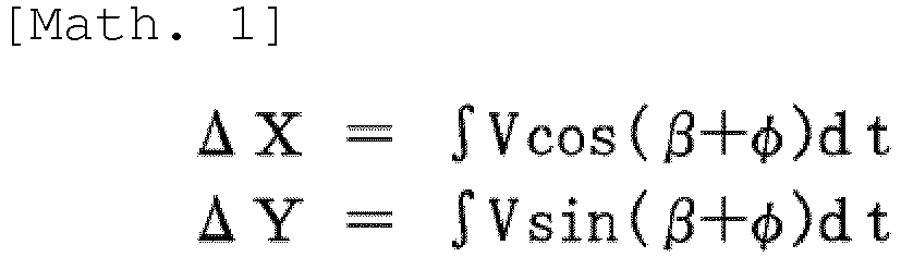


-
Embodiment 1 makes it possible to identify the traveling direction of thevehicle 4 by providing, for somemagnetic markers 5, the aforementioned azimuth identification section laid with amagnetic marker 5 and amagnetic marker 5p placed at a comparatively narrow spacing as shown inFIG. 8 . - As noted above, in the marker coordinate table of
FIG. 5 , themagnetic marker 5 configuring the azimuth identification section is distinguished by means of flag data corresponding to an open circle (o). For thismagnetic marker 5, section information on the azimuth identification section is recorded in addition to the laying position coordinates (Xn, Xy). The section information is information on a reference distance (span SL), i.e. a spacing between themagnetic marker 5 and themagnetic marker 5p, and a reference azimuth representing the direction of a line segment on which themagnetic marker 5 and themagnetic marker 5p are located. It should be noted thatFIG. 5 represents the reference azimuth clockwise based on true north. For example, as for the azimuth identification section of the marker m, the reference distance is 2000 mm and the reference azimuth is an azimuth of 235° clockwise based on true north. - During passage of the
vehicle 4 through the azimuth identification section, as shown inFIG. 8 , measuring a variation Δ in lateral shift amount during passage over the first and secondmagnetic markers vehicle 4 with respect to the reference azimuth according to the following equation. θ0 is an angle formed by the traveling direction of thevehicle 4 and the reference azimuth of the azimuth identification section. For example, in the case of the azimuth identification section of the marker m, an angle obtained by adding θ0 to the reference azimuth of 235° is the absolute azimuth of the traveling direction of thevehicle 4 based on true north.
- The following describes operation of the
navigation system 1 with reference to a flow chart ofFIG. 9 . Thenavigation unit 11 reads out surrounding map information with reference to themap database 113 by using the own vehicle position thus captured and displays the surrounding map information on theonboard display 131. When amagnetic marker 5 is detected upon entry into a road or the like laid withmagnetic markers 5, thenavigation system 1 according toEmbodiment 1 is brought into an operation mode in which to perform position capture by usingmagnetic markers 5. After that, when the distance moved since detection of themagnetic marker 5 has exceeded a predetermined distance after movement away from the road or the like laid withmagnetic markers 5, a switch is made to an operation mode in which nomagnetic markers 5 are used. In a road or section laid with nomagnetic markers 5, thenavigation system 1 operates in a manner which is similar to a manner of operation of a well-known navigation system including a positioning unit using satellite radio waves. - When the
vehicle 4 is traveling on a road or section laid withmagnetic markers 5, thenavigation unit 11 performs different operations depending on whether it has received a marker detection signal from the marker detection unit 15 (S101). - Upon receiving a marker detection signal (S101: YES), the
navigation unit 11 acquires, by computation, positioning position coordinates (GX, GY) serving as an actual measured position measured by positioning based on satellite radio waves (S102). Then, the positioning position coordinates (GX, GY) are used to select the nearest laying position coordinates (Xn, Yn) with reference to the marker coordinate table (FIG. 5 ) (S103). - Note here that in
Embodiment 1, as shown inFIG. 10 , the spacings at which themagnetic markers 5 are laid are 50 m, while the positioning accuracy based on satellite radio waves is 10 m. Therefore, there is less fear that the laying positions of two or moremagnetic markers 5 may fall within anerror circle 58 with a radius of 10 m of accuracy centered at an actual measured position based on satellite radio waves upon detection of any of themagnetic markers 5, and any of the nearest laying position coordinates (Xn, Xy) (seeFIG. 5 ) can be selected with high reliability. - The
navigation unit 11 finds a corrected position (PXn, PYn) obtained by correcting the laying position coordinates (Xn, Yn) with the lateral shift amount (Xof, Yof) received together with the marker detection signal (S104), and captures this corrected position (PXn, PYn) as the own vehicle position (PosX, PosY) (S105). - Having thus successfully captured the own vehicle position (PosX, PosY) by using a
magnetic marker 5, thenavigation unit 11 sets this own vehicle position (PosX, PosY) as a reference position (PXs, PYs) of inertial direction in a new own vehicle position estimation section (seeFIG. 7 ) until detection of the next magnetic marker 5 (S106). Further, in preparation for a new own vehicle position estimation section, thenavigation unit 11 resets the relative position coordinates (ΔX, ΔY), computed by inertial navigation, to zero for initialization (S107). - When the
vehicle 4 passes over amagnetic marker 5 and enters a new own vehicle position estimation section, no marker detection signal is to be received (S101: NO). Accordingly, thenavigation unit 11 computes, by inertial navigation, relative position coordinates (ΔX, ΔY) representing a displacement from the reference position (S112). Then, thenavigation unit 11 estimates the own vehicle position (PosX, PosY) by adding the relative position coordinates (ΔX, ΔY) to the reference position (PXs, PYs) (S113). In the own vehicle position estimation section (FIG. 7 ) until thevehicle 4 reaches the nextmagnetic marker 5, thenavigation unit 11 repeatedly executes a process of estimating the own vehicle position by inertial navigation. - As noted above, the
navigation system 1 according toEmbodiment 1 is characterized in a method for capturing the own vehicle position in a road or section laid withmagnetic markers 5. In a road laid withmagnetic markers 5, the actual measured position measured by theGPS positioning circuit 11A is hardly treated directly as the own vehicle position. When themagnetic marker 5 has been detected, the laying position located nearest to the actual measured position measured by theGPS positioning circuit 11A is selected from among the laying positions of a plurality ofmagnetic markers 5, and the own vehicle position is captured on the basis of this laying position. - Further, in the own vehicle position estimation section falling in a gap between adjacent
magnetic markers 5, the own vehicle position is estimated by inertial navigation in a state where the own vehicle position captured upon detection of themagnetic marker 5 is set as a reference position. A spacing between themagnetic markers 5 is as comparatively short as 50 m, so that there is little accumulation of estimation errors caused by inertial navigation. Therefore, the estimation accuracy by inertial navigation in the own vehicle position estimation section is with high accuracy that exceeds the ±10 m positioning accuracy by theGPS positioning circuit 11A. - In the
GPS positioning circuit 11A, error in the actual measured position becomes larger as radio wave conditions become worse due to an external environment such as a forest of buildings. The position capture method involving the use ofmagnetic markers 5 according toEmbodiment 1 is less susceptible to errors caused by theGPS positioning circuit 11A, as the actual measured position measured by theGPS positioning circuit 11A does not directly serve as the own vehicle position. Accordingly, the position capture method according toEmbodiment 1 makes it possible to capture the own vehicle position with high accuracy regardless of magnitude of a positioning error caused by theGPS positioning circuit 11A. - Thus, the
navigation system 1, which configures an example of a system according to the present invention, is an excellent system that can capture the own vehicle position with high accuracy by usingmagnetic markers 5. In a road or section laid withmagnetic markers 5, the own vehicle position can be captured with much higher accuracy than by a common navigation system that captures the own vehicle position by GPS positioning. Being able to capture the own vehicle position with high accuracy makes it possible to execute routing assistance such as a left turn, a right turn, diverging, or merging with high accuracy. Furthermore, the high-accuracy own vehicle position that thenavigation system 1 captures can be widely utilized in vehicle control systems such as automatic braking before a stop line of an intersection, lane-following steering, and automatic driving. - Instead of or in addition to the configuration of
Embodiment 1, the following configurations may be employed. Alternatively, a proper combination of the following configurations may be employed. -
Embodiment 1 illustrates thenavigation system 1 as an example of a system that executes the position capture method usingmagnetic markers 5. The system may be a system such as a lane departure warning system, an automatic steering system that enables lane-following traveling, an automatic vehicle-driving system, or an automatic bus operation system. In the case of these systems, high-accuracy automatic steering, automatic driving, and the like can be achieved by capturing the own vehicle position with high accuracy in a road or section laid withmagnetic markers 5. - In an automatic steering system, an automatic vehicle-driving system, an automatic bus operation system, and the like, it is necessary to incorporate, into a vehicle-side system, a control part that controls a vehicle so that the vehicle moves along a route laid with magnetic markers. Examples of the control part include a unit that controls a steering actuator that changes the steering angle of a steering wheel, a unit that controls a prime mover such as an engine or a motor in order to control the vehicle speed so that the vehicle can safely negotiate a curve on a route.
- There may also be such a configuration that the polarities of
magnetic markers 5 may be used to provide road information or the like to thevehicle 4 side. As noted above, in each of themagnetic sensors 170 of thesensor unit 17, an amorphous wire serving as a magneto-sensitive body is disposed along the vehicle width direction. Therefore, each of themagnetic sensors 170 outputs a positive or negative sensor signal depending on whether it is located on the right or left side of amagnetic marker 5. For example, in a case where amagnetic marker 5 relatively passes through the space between the eighthmagnetic sensor 170 and the ninthmagnetic sensor 170, the eighthmagnetic sensor 170 and the ninthmagnetic sensor 170 detect magnetic strengths that are opposite in polarity to each other as shown inFIG. 6 . For example, it is possible to determine the polarity of amagnetic marker 5 according to whether a magnetic strength represented by a sensor signal from amagnetic sensor 170 located on the left side of themagnetic marker 5 takes on a positive or negative value. - For example, the polarity of a
magnetic marker 5 may be changed according to the type of a lane. For example, N-polemagnetic markers 5N may be arranged in a first lane of a road with two lanes on each side and S-polemagnetic markers 5S may be arranged in a second lane; furthermore, as shown inFIG. 11 ,magnetic markers magnetic markers 5 makes it possible to acquire type information of a lane by determining the polarities ofmagnetic markers 5 detected. It is difficult to identify a lane with a width of approximately 4 m by using theGPS positioning circuit 11A whose positioning accuracy is ±10 m. Therefore, the method for identifying the type of a lane throughmagnetic markers 5 is effective. - In the case of the
navigation system 1 according toEmbodiment 1, eachvehicle 4 includes amarker database 114. This configuration may be replaced by connecting to an access point of an internet line by means of radio communication or providing, with a marker database, a server apparatus (not illustrated) that is accessible from a vehicle side by means of road/automobile communication or the like. The configuration may be such that laying position coordinates (Xn, Yn) are received in response to transmission to the server apparatus of positioning position coordinates (GX, GY) upon detection of amagnetic marker 5. - Although a configuration has been illustrated in which
magnetic markers 5 are laid along a lane,magnetic markers 5 may be laid along a particular route without being laid along a lane. Layingmagnetic markers 5 along a route that a vehicle should travel enables vehicle control such as automatic driving or automatic steering that, for example, causes thevehicle 4 to move along the route. For example, in the case of an automatic operation system or the like that causes buses or the like to automatically travel, there emerges a need for a traveling pattern that does not extend along a road direction or a lane direction, such as an action of entering a station or a terminal. Layingmagnetic markers 5 along a route of entry into a station or a terminal makes it possible to achieve automatic entry into the station, the terminal, or the like with high accuracy. - Further, a plurality of
magnetic markers 5 may be dispersedly placed without being laid along a route that a vehicle travels. When the vehicle has passed over any of themagnetic markers 5, the laying position of themagnetic marker 5 can be used to capture the own vehicle position. Themagnetic markers 5 need only be placed such that a spacing between adjacentmagnetic markers 5 is wider than the positioning accuracy by theGPS positioning circuit 11A. InEmbodiment 1, a spacing that is wider than an error circle of the actual measured position is set as the spacing betweenmagnetic markers 5. Instead of this, by using as a reference a value obtained by multiplying, by a coefficient, a maximum error anticipated in the actual measured position, a spacing that is wider than this value may be set as the spacing between magnetic markers. - While the specific examples of the present invention have been described above in detail as in the above embodiments, these specific examples merely describe examples of technologies included in the claims. Needless to say, the claims should not be restrictively construed by the configurations, numerical values, and so forth of the specific examples. The claims include technologies obtained by variously modifying, changing, and combining the specific examples as appropriate by using known technologies, knowledge, and so forth by people skilled in the art.
-
- 1
- navigation system (system)
- 11
- navigation unit
- 11A
- GPS positioning circuit (positioning part)
- 11B
- inertial navigation circuit (positioning part)
- 11C
- position capture circuit
- 11D
- information display circuit
- 112
- hard disk drive
- 113
- map database
- 114
- marker database
- 15
- marker detection unit (detection unit)
- 15A
- marker detection circuit
- 15B
- lateral shift amount computation circuit
- 17
- sensor unit (detection unit)
- 4
- vehicle
- 5
- magnetic marker
Claims (7)
- A position capture method for capturing an own vehicle position by using a positioning part that measures a position of a vehicle and a plurality of magnetic markers laid on a traveling path of the vehicle with their laying positions specified, comprising:upon detection of any of the plurality of magnetic markers, selecting, from among the laying positions of the plurality of magnetic markers, the laying position located nearest to an actual measured position measured by the positioning part; andcapturing, as the own vehicle position, the laying position or a corrected position based on the laying position.
- The position capture method according to claim 1, wherein the corrected position is captured as the own vehicle position, the corrected position being obtained by correcting the nearest laying position with a lateral shift amount, the lateral shift amount being a deviation of the vehicle in a vehicle width direction with respect to the magnetic marker thus detected.
- The position capture method according to claim 1 or 2, wherein a spacing between magnetic markers laid on the traveling path in order to capture the own vehicle position is set to be wider than a radius of an error circle within which the actual measured position measured by the positioning part falls with a predetermined probability or higher.
- The position capture method according to any one of claims 1 to 3, wherein during a period from capture of the own vehicle position upon detection of the magnetic marker to detection of another one of the magnetic markers, the own vehicle position is estimated by inertial navigation by which to find a displacement of the vehicle on the basis of information representing a motion of the vehicle.
- The position capture method according to claim 4, wherein an azimuth identification section is provided in which at least two magnetic markers are installed along a line segment whose azimuth and spacing are known, and a traveling direction of the vehicle with respect to the line segment is identified in the azimuth identification section.
- A system comprising:a positioning part that measures a position of a vehicle;a detection unit that detects magnetic markers laid on a traveling path of the vehicle; anda storage device in which to store position information representing positions in which the magnetic markers are laid,the system being configured to be able to capture an own vehicle position by using the position capture method according to any one of claims 1 to 5.
- The system according to claim 6, wherein the magnetic markers are laid along a predetermined route where the vehicle moves,
the system further comprising a control part that controls the vehicle so that the vehicle moves along the route.
Applications Claiming Priority (2)
| Application Number | Priority Date | Filing Date | Title |
|---|---|---|---|
| JP2016111996 | 2016-06-03 | ||
| PCT/JP2017/020048 WO2017209112A1 (en) | 2016-06-03 | 2017-05-30 | Position capture method and system |
Publications (3)
| Publication Number | Publication Date |
|---|---|
| EP3467437A1 true EP3467437A1 (en) | 2019-04-10 |
| EP3467437A4 EP3467437A4 (en) | 2019-06-05 |
| EP3467437B1 EP3467437B1 (en) | 2022-03-02 |
Family
ID=60478713
Family Applications (1)
| Application Number | Title | Priority Date | Filing Date |
|---|---|---|---|
| EP17806665.0A Active EP3467437B1 (en) | 2016-06-03 | 2017-05-30 | Position capture method and system |
Country Status (6)
| Country | Link |
|---|---|
| US (1) | US11049392B2 (en) |
| EP (1) | EP3467437B1 (en) |
| JP (1) | JP6916784B2 (en) |
| CN (1) | CN109661563B (en) |
| SG (1) | SG11201810744UA (en) |
| WO (1) | WO2017209112A1 (en) |
Cited By (4)
| Publication number | Priority date | Publication date | Assignee | Title |
|---|---|---|---|---|
| EP3637384A4 (en) * | 2017-06-06 | 2021-01-06 | Aichi Steel Corporation | MARKER SYSTEM AND METHOD OF USE |
| EP3683547A4 (en) * | 2017-09-12 | 2021-05-26 | Aichi Steel Corporation | POSITION CAPTURE SYSTEM AND POSITION CAPTURE METHOD |
| CN114730524A (en) * | 2019-11-22 | 2022-07-08 | 爱知制钢株式会社 | Position estimation method and position estimation system |
| EP4318436A4 (en) * | 2021-04-01 | 2025-03-26 | Aichi Steel Corporation | METHOD AND SYSTEM FOR DETECTING MAGNETIC MARKER |
Families Citing this family (29)
| Publication number | Priority date | Publication date | Assignee | Title |
|---|---|---|---|---|
| JP6365601B2 (en) * | 2016-07-11 | 2018-08-01 | 愛知製鋼株式会社 | Magnetic marker detection system and magnetic marker detection method |
| EP3605487A4 (en) * | 2017-03-28 | 2020-10-07 | Aichi Steel Corporation | Marker system |
| JP6920975B2 (en) * | 2017-12-12 | 2021-08-18 | 愛知製鋼株式会社 | Construction equipment, construction method, and construction system |
| CN111629944B (en) | 2018-02-01 | 2023-05-02 | 本田技研工业株式会社 | Vehicle control device, vehicle, and vehicle control method |
| WO2019156914A1 (en) * | 2018-02-07 | 2019-08-15 | 3M Innovative Properties Company | Validating vehicle operation using pathway articles |
| DE112018007180T5 (en) | 2018-02-28 | 2020-12-10 | Honda Motor Co., Ltd. | LOCATION ESTIMATION DEVICE, MOVING OBJECT, LOCATION ESTIMATION METHOD AND PROGRAM |
| JP7147275B2 (en) * | 2018-06-04 | 2022-10-05 | 愛知製鋼株式会社 | How to calibrate the gyro sensor |
| KR102122747B1 (en) * | 2018-08-02 | 2020-06-16 | 주식회사 정석케미칼 | Method for generating magnetic field and method for detecting lane using magnetic field, vehcle using the same |
| JP7255127B2 (en) * | 2018-10-04 | 2023-04-11 | 愛知製鋼株式会社 | magnetic marker system |
| US11604476B1 (en) * | 2018-10-05 | 2023-03-14 | Glydways Inc. | Road-based vehicle guidance system |
| DE102018222643A1 (en) * | 2018-12-20 | 2020-06-25 | Robert Bosch Gmbh | 5Procedure for determining a UERE, method for determining a UERE, computer-implemented data structure, use, device and computer-implemented program |
| WO2020138467A1 (en) * | 2018-12-28 | 2020-07-02 | 愛知製鋼株式会社 | Travel path diagnostic system |
| EP3904187B1 (en) * | 2018-12-28 | 2024-12-25 | Aichi Steel Corporation | Correction method for gyro sensor |
| WO2020138465A1 (en) * | 2018-12-28 | 2020-07-02 | 愛知製鋼株式会社 | Vehicle and vehicle diagnostic system |
| EP3989199A4 (en) * | 2019-06-21 | 2023-07-19 | Aichi Steel Corporation | CONTROL METHOD AND CONTROL SYSTEM FOR VEHICLE |
| CN114761758A (en) * | 2019-11-04 | 2022-07-15 | 动态清晰公司 | Multi-lane road characterization and tracking algorithm |
| JP7537170B2 (en) * | 2020-08-07 | 2024-08-21 | 株式会社ジェイテクト | Driving support device and magnetic marker installation method |
| CN111815964B (en) * | 2020-09-02 | 2020-12-29 | 四川九通智路科技有限公司 | Traffic flow detection system and method based on geomagnetic sensing type spike |
| WO2022154103A1 (en) * | 2021-01-18 | 2022-07-21 | 愛知製鋼株式会社 | Control method and control system |
| WO2022210194A1 (en) * | 2021-04-01 | 2022-10-06 | 愛知製鋼株式会社 | System |
| JP7817594B2 (en) * | 2021-06-25 | 2026-02-19 | 愛知製鋼株式会社 | Vehicle Systems |
| JP7787432B2 (en) * | 2021-06-25 | 2025-12-17 | 愛知製鋼株式会社 | Magnetic marker detection method and detection system |
| JP2025535195A (en) * | 2022-10-17 | 2025-10-22 | インベンセンス・インコーポレーテッド | Terminal device, magnetic anchor system and positioning method |
| JP2024122563A (en) * | 2023-02-28 | 2024-09-09 | トヨタ自動車株式会社 | Control device |
| CN116793339B (en) * | 2023-08-29 | 2023-11-07 | 深圳智荟物联技术有限公司 | Vehicle positioning method, device, equipment and storage medium |
| CN117468389B (en) * | 2023-09-13 | 2026-07-14 | 南京航空航天大学 | Track laying method and unmanned vehicle magnetic nail navigation method |
| US20250182620A1 (en) * | 2023-10-19 | 2025-06-05 | The Board Of Trustees Of The University Of Illinois | Passive In-Vehicle Sensing of Pavement Signage Coded on Roadways |
| CN117240347B (en) * | 2023-11-15 | 2024-02-20 | 江苏领创星通卫星通信科技有限公司 | Testing assembly of satellite communication terminal |
| US12479469B2 (en) * | 2023-11-22 | 2025-11-25 | Automotive Research & Testing Center | Deciding system for moving vehicle on virtual rail and method thereof |
Family Cites Families (51)
| Publication number | Priority date | Publication date | Assignee | Title |
|---|---|---|---|---|
| US4817000A (en) * | 1986-03-10 | 1989-03-28 | Si Handling Systems, Inc. | Automatic guided vehicle system |
| FR2610427B1 (en) * | 1987-02-04 | 1995-09-29 | Protee | SYSTEM AND METHOD FOR MONITORING THE RUNNING OF A SELF-CONTAINED VEHICLE |
| JPH07120194B2 (en) * | 1988-03-31 | 1995-12-20 | 株式会社椿本チエイン | Driving control method and apparatus for automatic guided vehicle |
| US5191528A (en) | 1990-06-28 | 1993-03-02 | Eaton-Kenway, Inc. | Update marker system for naviagtion of an automatic guided vehicle |
| US5347456A (en) * | 1991-05-22 | 1994-09-13 | The Regents Of The University Of California | Intelligent roadway reference system for vehicle lateral guidance and control |
| US5357437A (en) * | 1992-07-01 | 1994-10-18 | Westinghouse Electric Corporation | Magnetic marker position fixing system for underwater vehicles |
| JPH0634743A (en) * | 1992-07-20 | 1994-02-10 | Railway Technical Res Inst | Mobile object position detector |
| JPH08136273A (en) * | 1994-11-08 | 1996-05-31 | Oki Electric Ind Co Ltd | Car navigation system |
| US6012013A (en) * | 1995-03-31 | 2000-01-04 | Trimble Navigation Limited | Vehicle position reporting in user defined uni-dimensional coordinate system |
| US6938829B2 (en) * | 1996-06-07 | 2005-09-06 | John A. Doherty | Apparatus and system for synchronized application of one or more materials to a surface from a vehicle and control of a vehicle mounted variable position snow removal device |
| US5913376A (en) * | 1995-10-31 | 1999-06-22 | Honda Giken Kogyo Kabushiki Kaisha | Automatic steering control apparatus |
| JPH1047983A (en) | 1996-08-05 | 1998-02-20 | Sumitomo Electric Ind Ltd | Vehicle position detection device |
| JP3689993B2 (en) * | 1996-09-10 | 2005-08-31 | マツダ株式会社 | Vehicle position and direction angle detection device |
| JP3773218B2 (en) * | 1996-09-26 | 2006-05-10 | 本田技研工業株式会社 | Automatic running path and automatic running magnet generator |
| EP1439371B1 (en) * | 1996-11-25 | 2015-01-28 | Toyota Jidosha Kabushiki Kaisha | Road shape data preparation method |
| US6092010A (en) * | 1997-09-03 | 2000-07-18 | Jervis B. Webb Company | Method and system for describing, generating and checking non-wire guidepaths for automatic guided vehicles |
| US5926126A (en) * | 1997-09-08 | 1999-07-20 | Ford Global Technologies, Inc. | Method and system for detecting an in-path target obstacle in front of a vehicle |
| CN1117965C (en) * | 1997-09-29 | 2003-08-13 | 爱知制钢株式会社 | Magnetic apparatus for detecting position of vehicle |
| JP3262051B2 (en) * | 1997-10-22 | 2002-03-04 | 日本電気株式会社 | Vehicle position detecting device and position detecting method |
| US7298289B1 (en) * | 1998-01-27 | 2007-11-20 | Hoffberg Steven M | Mobile communication device |
| US7268700B1 (en) * | 1998-01-27 | 2007-09-11 | Hoffberg Steven M | Mobile communication device |
| JP2000322691A (en) * | 1999-05-12 | 2000-11-24 | Sumitomo Electric Ind Ltd | Position adjustment device for magnetic sensor |
| JP2001101588A (en) * | 1999-09-30 | 2001-04-13 | Toshiba Corp | Route bus operation management system |
| JP3174832B2 (en) * | 1999-10-27 | 2001-06-11 | 建設省土木研究所長 | Crossing pedestrian collision prevention system |
| JP2002063682A (en) * | 2000-08-21 | 2002-02-28 | Nec Corp | Travel position detector |
| US6728629B2 (en) * | 2000-11-24 | 2004-04-27 | National Institute For Land And Infrastructure Management, Ministry Of Land, Infrastructure And Transport | On-road reference point positional data delivery device |
| US6377211B1 (en) * | 2000-12-13 | 2002-04-23 | Lockheed Martin Corporation | Apparatus and method for pointing a directional device from a moving vehicle toward a spacecraft |
| JP3839678B2 (en) * | 2001-03-27 | 2006-11-01 | 三菱電機株式会社 | Vehicle position recognition device |
| JP2002286456A (en) * | 2001-03-27 | 2002-10-03 | Mitsubishi Electric Corp | Vehicle position recognition device |
| JP2002334400A (en) * | 2001-05-10 | 2002-11-22 | Mitsubishi Motors Corp | Driving support device |
| US6772062B2 (en) * | 2001-05-31 | 2004-08-03 | The Regents Of The University Of California | Intelligent ultra high speed distributed sensing system and method for sensing roadway markers for intelligent vehicle guidance and control |
| DE10210546A1 (en) * | 2002-03-09 | 2003-09-18 | Bosch Gmbh Robert | Automatic vehicle control method and system |
| JP3772838B2 (en) * | 2003-02-12 | 2006-05-10 | トヨタ自動車株式会社 | VEHICLE DRIVE SUPPORT DEVICE AND VEHICLE CONTROL DEVICE |
| JP2004342083A (en) * | 2003-04-22 | 2004-12-02 | Toshiba Corp | VEHICLE DRIVING MANAGEMENT SYSTEM, ON-BOARD DEVICE USED FOR THE VEHICLE DRIVING MANAGEMENT SYSTEM, AND VEHICLE DRIVING MANAGEMENT METHOD |
| JP2005226670A (en) * | 2004-02-10 | 2005-08-25 | Toyota Motor Corp | Vehicle deceleration control device |
| JP2005297611A (en) * | 2004-04-06 | 2005-10-27 | Toyota Motor Corp | Vehicle deceleration control device |
| JP4822099B2 (en) * | 2005-07-11 | 2011-11-24 | アイシン・エィ・ダブリュ株式会社 | Navigation device and navigation method |
| US8311730B2 (en) * | 2006-11-29 | 2012-11-13 | Neff Ryan A | Vehicle position determination system |
| US8532862B2 (en) * | 2006-11-29 | 2013-09-10 | Ryan A. Neff | Driverless vehicle |
| JP4586795B2 (en) * | 2006-12-07 | 2010-11-24 | トヨタ自動車株式会社 | Vehicle control device |
| US20090128139A1 (en) | 2007-11-20 | 2009-05-21 | Drenth Joseph B | Magnet position locator |
| CN102027519B (en) * | 2008-07-10 | 2013-12-18 | 三菱电机株式会社 | Train-of-vehicle travel support device |
| WO2012074935A2 (en) * | 2010-11-29 | 2012-06-07 | Washington State University Research Foundation | Alertness monitoring systems and associated methods |
| US8880273B1 (en) * | 2013-01-16 | 2014-11-04 | Google Inc. | System and method for determining position and distance of objects using road fiducials |
| US20150045986A1 (en) * | 2013-08-09 | 2015-02-12 | Pulsar Informatics, Inc. | Systems and Methods for Determining Driver Fatigue Level from Lane Variability and Geographic Location |
| CN103499351A (en) * | 2013-09-03 | 2014-01-08 | 北京工业大学 | Vehicles assisted positioning method based on magnetic landmarks and magnetic sensors |
| WO2015052865A1 (en) * | 2013-10-11 | 2015-04-16 | 日産自動車株式会社 | Travel control device and travel control method |
| US20150294566A1 (en) * | 2014-04-15 | 2015-10-15 | Tomorrow's Transportation Today | Trip planning and management methods for an intelligent transit system with electronic guided buses |
| US20150294430A1 (en) * | 2014-04-15 | 2015-10-15 | Tomorrow's Transportation Today | Dynamic dispatching and schedule management methods for an intelligent transit system with electronic guided buses |
| CN104460665A (en) * | 2014-10-13 | 2015-03-25 | 上海交通大学 | Magnetic navigation unmanned vehicle based on road curvature map and road curvature map establishment method |
| US9892296B2 (en) * | 2014-11-12 | 2018-02-13 | Joseph E. Kovarik | Method and system for autonomous vehicles |
-
2017
- 2017-05-30 WO PCT/JP2017/020048 patent/WO2017209112A1/en not_active Ceased
- 2017-05-30 SG SG11201810744UA patent/SG11201810744UA/en unknown
- 2017-05-30 US US16/305,883 patent/US11049392B2/en active Active
- 2017-05-30 CN CN201780032509.6A patent/CN109661563B/en active Active
- 2017-05-30 EP EP17806665.0A patent/EP3467437B1/en active Active
- 2017-05-30 JP JP2018520921A patent/JP6916784B2/en active Active
Cited By (9)
| Publication number | Priority date | Publication date | Assignee | Title |
|---|---|---|---|---|
| EP3637384A4 (en) * | 2017-06-06 | 2021-01-06 | Aichi Steel Corporation | MARKER SYSTEM AND METHOD OF USE |
| US11231721B2 (en) | 2017-06-06 | 2022-01-25 | Aichi Steel Corporation | Marker system and operation method |
| EP3683547A4 (en) * | 2017-09-12 | 2021-05-26 | Aichi Steel Corporation | POSITION CAPTURE SYSTEM AND POSITION CAPTURE METHOD |
| US11287263B2 (en) | 2017-09-12 | 2022-03-29 | Aichi Steel Corporation | Position capturing system and position capturing method |
| CN114730524A (en) * | 2019-11-22 | 2022-07-08 | 爱知制钢株式会社 | Position estimation method and position estimation system |
| EP4064251A4 (en) * | 2019-11-22 | 2023-12-13 | Aichi Steel Corporation | Location estimation method and location estimation system |
| US12236781B2 (en) | 2019-11-22 | 2025-02-25 | Aichi Steel Corporation | Position estimation method and position estimation system |
| EP4318436A4 (en) * | 2021-04-01 | 2025-03-26 | Aichi Steel Corporation | METHOD AND SYSTEM FOR DETECTING MAGNETIC MARKER |
| US12516958B2 (en) | 2021-04-01 | 2026-01-06 | Aichi Steel Corporation | Magnetic marker detection method and system |
Also Published As
| Publication number | Publication date |
|---|---|
| CN109661563A (en) | 2019-04-19 |
| JP6916784B2 (en) | 2021-08-11 |
| EP3467437B1 (en) | 2022-03-02 |
| EP3467437A4 (en) | 2019-06-05 |
| CN109661563B (en) | 2023-09-01 |
| US20200320870A1 (en) | 2020-10-08 |
| JPWO2017209112A1 (en) | 2019-03-28 |
| US11049392B2 (en) | 2021-06-29 |
| WO2017209112A1 (en) | 2017-12-07 |
| SG11201810744UA (en) | 2019-01-30 |
Similar Documents
| Publication | Publication Date | Title |
|---|---|---|
| EP3467437B1 (en) | Position capture method and system | |
| CN110709906B (en) | Marker system and application method | |
| EP3509048B1 (en) | Vehicle system and path estimation method | |
| CN110402311B (en) | Construction method and operating system of magnetic marker | |
| EP3683547B1 (en) | Position capturing system and position capturing method | |
| JP2019045379A (en) | Vehicle position estimation device | |
| WO1999017079A1 (en) | Magnetic apparatus for detecting position of vehicle | |
| JP6451857B2 (en) | Method for controlling travel control device and travel control device | |
| US11608059B2 (en) | Method and apparatus for method for real time lateral control and steering actuation assessment | |
| CN110419067A (en) | Concentrator marker system | |
| KR20000053026A (en) | Position location system for vehicle fitted with a satellite signal receiver | |
| CN108340922A (en) | The method and apparatus for determining road surface road conditions | |
| WO2019046504A1 (en) | Lane marker signal improvement through mapped geo-referenced boundaries | |
| JP3743071B2 (en) | Lane departure warning device | |
| JP2015072636A (en) | Information processing device | |
| JP3755217B2 (en) | Vehicle position calculation device | |
| JP7817594B2 (en) | Vehicle Systems | |
| JP7151747B2 (en) | Vehicle system and route estimation method | |
| JPH10100821A (en) | Forward vehicle recognition device | |
| KR20090049500A (en) | Location Estimation Device and Method Using Driving Record Data of Vehicle | |
| JPH08194535A (en) | Position detection system | |
| JPH049711A (en) | Detecting apparatus for position of vehicle |
Legal Events
| Date | Code | Title | Description |
|---|---|---|---|
| STAA | Information on the status of an ep patent application or granted ep patent |
Free format text: STATUS: THE INTERNATIONAL PUBLICATION HAS BEEN MADE |
|
| PUAI | Public reference made under article 153(3) epc to a published international application that has entered the european phase |
Free format text: ORIGINAL CODE: 0009012 |
|
| STAA | Information on the status of an ep patent application or granted ep patent |
Free format text: STATUS: REQUEST FOR EXAMINATION WAS MADE |
|
| 17P | Request for examination filed |
Effective date: 20181127 |
|
| AK | Designated contracting states |
Kind code of ref document: A1 Designated state(s): AL AT BE BG CH CY CZ DE DK EE ES FI FR GB GR HR HU IE IS IT LI LT LU LV MC MK MT NL NO PL PT RO RS SE SI SK SM TR |
|
| AX | Request for extension of the european patent |
Extension state: BA ME |
|
| A4 | Supplementary search report drawn up and despatched |
Effective date: 20190506 |
|
| RIC1 | Information provided on ipc code assigned before grant |
Ipc: G01C 21/28 20060101AFI20190429BHEP Ipc: G05D 1/02 20060101ALI20190429BHEP Ipc: G08G 1/00 20060101ALI20190429BHEP |
|
| DAV | Request for validation of the european patent (deleted) | ||
| DAX | Request for extension of the european patent (deleted) | ||
| STAA | Information on the status of an ep patent application or granted ep patent |
Free format text: STATUS: EXAMINATION IS IN PROGRESS |
|
| 17Q | First examination report despatched |
Effective date: 20200824 |
|
| REG | Reference to a national code |
Ref country code: DE Ref legal event code: R079 Ref document number: 602017054118 Country of ref document: DE Free format text: PREVIOUS MAIN CLASS: G01C0021280000 Ipc: G01C0021160000 |
|
| RAP3 | Party data changed (applicant data changed or rights of an application transferred) |
Owner name: ADVANCED SMART MOBILITY CO., LTD. Owner name: AICHI STEEL CORPORATION |
|
| RIC1 | Information provided on ipc code assigned before grant |
Ipc: G05D 1/02 20200101ALI20210629BHEP Ipc: G01C 21/28 20060101ALI20210629BHEP Ipc: G01C 21/04 20060101ALI20210629BHEP Ipc: G08G 1/056 20060101ALI20210629BHEP Ipc: G08G 1/042 20060101ALI20210629BHEP Ipc: G01S 19/50 20100101ALI20210629BHEP Ipc: G01S 19/48 20100101ALI20210629BHEP Ipc: G01S 19/14 20100101ALI20210629BHEP Ipc: G01C 21/16 20060101AFI20210629BHEP |
|
| GRAP | Despatch of communication of intention to grant a patent |
Free format text: ORIGINAL CODE: EPIDOSNIGR1 |
|
| STAA | Information on the status of an ep patent application or granted ep patent |
Free format text: STATUS: GRANT OF PATENT IS INTENDED |
|
| INTG | Intention to grant announced |
Effective date: 20210920 |
|
| RIN1 | Information on inventor provided before grant (corrected) |
Inventor name: AOKI KEIJI Inventor name: AOYAMA, HITOSHI Inventor name: NAGAO, TOMOHIKO Inventor name: YAMAMOTO, MICHIHARU |
|
| GRAS | Grant fee paid |
Free format text: ORIGINAL CODE: EPIDOSNIGR3 |
|
| GRAA | (expected) grant |
Free format text: ORIGINAL CODE: 0009210 |
|
| STAA | Information on the status of an ep patent application or granted ep patent |
Free format text: STATUS: THE PATENT HAS BEEN GRANTED |
|
| REG | Reference to a national code |
Ref country code: DE Ref legal event code: R081 Ref document number: 602017054118 Country of ref document: DE Owner name: AICHI STEEL CORPORATION, TOKAI-SHI, JP Free format text: FORMER OWNERS: ADVANCED SMART MOBILITY CO., LTD., TSUKUBA-SHI, IBARAKI, JP; AICHI STEEL CORPORATION, TOKAI-SHI, AICHI, JP Ref country code: DE Ref legal event code: R081 Ref document number: 602017054118 Country of ref document: DE Owner name: ADVANCED SMART MOBILITY CO., LTD., TSUKUBA-SHI, JP Free format text: FORMER OWNERS: ADVANCED SMART MOBILITY CO., LTD., TSUKUBA-SHI, IBARAKI, JP; AICHI STEEL CORPORATION, TOKAI-SHI, AICHI, JP |
|
| AK | Designated contracting states |
Kind code of ref document: B1 Designated state(s): AL AT BE BG CH CY CZ DE DK EE ES FI FR GB GR HR HU IE IS IT LI LT LU LV MC MK MT NL NO PL PT RO RS SE SI SK SM TR |
|
| REG | Reference to a national code |
Ref country code: GB Ref legal event code: FG4D |
|
| REG | Reference to a national code |
Ref country code: CH Ref legal event code: EP Ref country code: AT Ref legal event code: REF Ref document number: 1472594 Country of ref document: AT Kind code of ref document: T Effective date: 20220315 |
|
| REG | Reference to a national code |
Ref country code: DE Ref legal event code: R096 Ref document number: 602017054118 Country of ref document: DE |
|
| REG | Reference to a national code |
Ref country code: IE Ref legal event code: FG4D |
|
| REG | Reference to a national code |
Ref country code: NL Ref legal event code: FP |
|
| REG | Reference to a national code |
Ref country code: SE Ref legal event code: TRGR |
|
| REG | Reference to a national code |
Ref country code: LT Ref legal event code: MG9D |
|
| PG25 | Lapsed in a contracting state [announced via postgrant information from national office to epo] |
Ref country code: RS Free format text: LAPSE BECAUSE OF FAILURE TO SUBMIT A TRANSLATION OF THE DESCRIPTION OR TO PAY THE FEE WITHIN THE PRESCRIBED TIME-LIMIT Effective date: 20220302 Ref country code: NO Free format text: LAPSE BECAUSE OF FAILURE TO SUBMIT A TRANSLATION OF THE DESCRIPTION OR TO PAY THE FEE WITHIN THE PRESCRIBED TIME-LIMIT Effective date: 20220602 Ref country code: LT Free format text: LAPSE BECAUSE OF FAILURE TO SUBMIT A TRANSLATION OF THE DESCRIPTION OR TO PAY THE FEE WITHIN THE PRESCRIBED TIME-LIMIT Effective date: 20220302 Ref country code: HR Free format text: LAPSE BECAUSE OF FAILURE TO SUBMIT A TRANSLATION OF THE DESCRIPTION OR TO PAY THE FEE WITHIN THE PRESCRIBED TIME-LIMIT Effective date: 20220302 Ref country code: ES Free format text: LAPSE BECAUSE OF FAILURE TO SUBMIT A TRANSLATION OF THE DESCRIPTION OR TO PAY THE FEE WITHIN THE PRESCRIBED TIME-LIMIT Effective date: 20220302 Ref country code: BG Free format text: LAPSE BECAUSE OF FAILURE TO SUBMIT A TRANSLATION OF THE DESCRIPTION OR TO PAY THE FEE WITHIN THE PRESCRIBED TIME-LIMIT Effective date: 20220602 |
|
| REG | Reference to a national code |
Ref country code: AT Ref legal event code: MK05 Ref document number: 1472594 Country of ref document: AT Kind code of ref document: T Effective date: 20220302 |
|
| PG25 | Lapsed in a contracting state [announced via postgrant information from national office to epo] |
Ref country code: PL Free format text: LAPSE BECAUSE OF FAILURE TO SUBMIT A TRANSLATION OF THE DESCRIPTION OR TO PAY THE FEE WITHIN THE PRESCRIBED TIME-LIMIT Effective date: 20220302 Ref country code: LV Free format text: LAPSE BECAUSE OF FAILURE TO SUBMIT A TRANSLATION OF THE DESCRIPTION OR TO PAY THE FEE WITHIN THE PRESCRIBED TIME-LIMIT Effective date: 20220302 Ref country code: GR Free format text: LAPSE BECAUSE OF FAILURE TO SUBMIT A TRANSLATION OF THE DESCRIPTION OR TO PAY THE FEE WITHIN THE PRESCRIBED TIME-LIMIT Effective date: 20220603 Ref country code: FI Free format text: LAPSE BECAUSE OF FAILURE TO SUBMIT A TRANSLATION OF THE DESCRIPTION OR TO PAY THE FEE WITHIN THE PRESCRIBED TIME-LIMIT Effective date: 20220302 |
|
| PG25 | Lapsed in a contracting state [announced via postgrant information from national office to epo] |
Ref country code: SM Free format text: LAPSE BECAUSE OF FAILURE TO SUBMIT A TRANSLATION OF THE DESCRIPTION OR TO PAY THE FEE WITHIN THE PRESCRIBED TIME-LIMIT Effective date: 20220302 Ref country code: SK Free format text: LAPSE BECAUSE OF FAILURE TO SUBMIT A TRANSLATION OF THE DESCRIPTION OR TO PAY THE FEE WITHIN THE PRESCRIBED TIME-LIMIT Effective date: 20220302 Ref country code: RO Free format text: LAPSE BECAUSE OF FAILURE TO SUBMIT A TRANSLATION OF THE DESCRIPTION OR TO PAY THE FEE WITHIN THE PRESCRIBED TIME-LIMIT Effective date: 20220302 Ref country code: PT Free format text: LAPSE BECAUSE OF FAILURE TO SUBMIT A TRANSLATION OF THE DESCRIPTION OR TO PAY THE FEE WITHIN THE PRESCRIBED TIME-LIMIT Effective date: 20220704 Ref country code: EE Free format text: LAPSE BECAUSE OF FAILURE TO SUBMIT A TRANSLATION OF THE DESCRIPTION OR TO PAY THE FEE WITHIN THE PRESCRIBED TIME-LIMIT Effective date: 20220302 Ref country code: CZ Free format text: LAPSE BECAUSE OF FAILURE TO SUBMIT A TRANSLATION OF THE DESCRIPTION OR TO PAY THE FEE WITHIN THE PRESCRIBED TIME-LIMIT Effective date: 20220302 Ref country code: AT Free format text: LAPSE BECAUSE OF FAILURE TO SUBMIT A TRANSLATION OF THE DESCRIPTION OR TO PAY THE FEE WITHIN THE PRESCRIBED TIME-LIMIT Effective date: 20220302 |
|
| PG25 | Lapsed in a contracting state [announced via postgrant information from national office to epo] |
Ref country code: IS Free format text: LAPSE BECAUSE OF FAILURE TO SUBMIT A TRANSLATION OF THE DESCRIPTION OR TO PAY THE FEE WITHIN THE PRESCRIBED TIME-LIMIT Effective date: 20220702 Ref country code: AL Free format text: LAPSE BECAUSE OF FAILURE TO SUBMIT A TRANSLATION OF THE DESCRIPTION OR TO PAY THE FEE WITHIN THE PRESCRIBED TIME-LIMIT Effective date: 20220302 |
|
| REG | Reference to a national code |
Ref country code: DE Ref legal event code: R097 Ref document number: 602017054118 Country of ref document: DE |
|
| REG | Reference to a national code |
Ref country code: CH Ref legal event code: PL |
|
| PLBE | No opposition filed within time limit |
Free format text: ORIGINAL CODE: 0009261 |
|
| STAA | Information on the status of an ep patent application or granted ep patent |
Free format text: STATUS: NO OPPOSITION FILED WITHIN TIME LIMIT |
|
| REG | Reference to a national code |
Ref country code: BE Ref legal event code: MM Effective date: 20220531 |
|
| PG25 | Lapsed in a contracting state [announced via postgrant information from national office to epo] |
Ref country code: MC Free format text: LAPSE BECAUSE OF FAILURE TO SUBMIT A TRANSLATION OF THE DESCRIPTION OR TO PAY THE FEE WITHIN THE PRESCRIBED TIME-LIMIT Effective date: 20220302 Ref country code: LU Free format text: LAPSE BECAUSE OF NON-PAYMENT OF DUE FEES Effective date: 20220530 Ref country code: LI Free format text: LAPSE BECAUSE OF NON-PAYMENT OF DUE FEES Effective date: 20220531 Ref country code: DK Free format text: LAPSE BECAUSE OF FAILURE TO SUBMIT A TRANSLATION OF THE DESCRIPTION OR TO PAY THE FEE WITHIN THE PRESCRIBED TIME-LIMIT Effective date: 20220302 Ref country code: CH Free format text: LAPSE BECAUSE OF NON-PAYMENT OF DUE FEES Effective date: 20220531 |
|
| 26N | No opposition filed |
Effective date: 20221205 |
|
| PG25 | Lapsed in a contracting state [announced via postgrant information from national office to epo] |
Ref country code: SI Free format text: LAPSE BECAUSE OF FAILURE TO SUBMIT A TRANSLATION OF THE DESCRIPTION OR TO PAY THE FEE WITHIN THE PRESCRIBED TIME-LIMIT Effective date: 20220302 |
|
| PG25 | Lapsed in a contracting state [announced via postgrant information from national office to epo] |
Ref country code: IE Free format text: LAPSE BECAUSE OF NON-PAYMENT OF DUE FEES Effective date: 20220530 |
|
| PG25 | Lapsed in a contracting state [announced via postgrant information from national office to epo] |
Ref country code: BE Free format text: LAPSE BECAUSE OF NON-PAYMENT OF DUE FEES Effective date: 20220531 |
|
| P01 | Opt-out of the competence of the unified patent court (upc) registered |
Effective date: 20230413 |
|
| PG25 | Lapsed in a contracting state [announced via postgrant information from national office to epo] |
Ref country code: HU Free format text: LAPSE BECAUSE OF FAILURE TO SUBMIT A TRANSLATION OF THE DESCRIPTION OR TO PAY THE FEE WITHIN THE PRESCRIBED TIME-LIMIT; INVALID AB INITIO Effective date: 20170530 |
|
| PG25 | Lapsed in a contracting state [announced via postgrant information from national office to epo] |
Ref country code: MK Free format text: LAPSE BECAUSE OF FAILURE TO SUBMIT A TRANSLATION OF THE DESCRIPTION OR TO PAY THE FEE WITHIN THE PRESCRIBED TIME-LIMIT Effective date: 20220302 Ref country code: CY Free format text: LAPSE BECAUSE OF FAILURE TO SUBMIT A TRANSLATION OF THE DESCRIPTION OR TO PAY THE FEE WITHIN THE PRESCRIBED TIME-LIMIT Effective date: 20220302 |
|
| PG25 | Lapsed in a contracting state [announced via postgrant information from national office to epo] |
Ref country code: TR Free format text: LAPSE BECAUSE OF FAILURE TO SUBMIT A TRANSLATION OF THE DESCRIPTION OR TO PAY THE FEE WITHIN THE PRESCRIBED TIME-LIMIT Effective date: 20220302 |
|
| PG25 | Lapsed in a contracting state [announced via postgrant information from national office to epo] |
Ref country code: MT Free format text: LAPSE BECAUSE OF FAILURE TO SUBMIT A TRANSLATION OF THE DESCRIPTION OR TO PAY THE FEE WITHIN THE PRESCRIBED TIME-LIMIT Effective date: 20220302 |
|
| PGFP | Annual fee paid to national office [announced via postgrant information from national office to epo] |
Ref country code: NL Payment date: 20250521 Year of fee payment: 9 |
|
| PGFP | Annual fee paid to national office [announced via postgrant information from national office to epo] |
Ref country code: DE Payment date: 20250521 Year of fee payment: 9 |
|
| PGFP | Annual fee paid to national office [announced via postgrant information from national office to epo] |
Ref country code: GB Payment date: 20250527 Year of fee payment: 9 |
|
| PGFP | Annual fee paid to national office [announced via postgrant information from national office to epo] |
Ref country code: IT Payment date: 20250527 Year of fee payment: 9 |
|
| PGFP | Annual fee paid to national office [announced via postgrant information from national office to epo] |
Ref country code: FR Payment date: 20250528 Year of fee payment: 9 |
|
| PGFP | Annual fee paid to national office [announced via postgrant information from national office to epo] |
Ref country code: SE Payment date: 20250521 Year of fee payment: 9 |