EP3467396B1 - Wassererhitzer mit verbesserter erdungseigenschaft - Google Patents
Wassererhitzer mit verbesserter erdungseigenschaft Download PDFInfo
- Publication number
- EP3467396B1 EP3467396B1 EP18197188.8A EP18197188A EP3467396B1 EP 3467396 B1 EP3467396 B1 EP 3467396B1 EP 18197188 A EP18197188 A EP 18197188A EP 3467396 B1 EP3467396 B1 EP 3467396B1
- Authority
- EP
- European Patent Office
- Prior art keywords
- water heater
- cable
- phase
- heater according
- earth
- Prior art date
- Legal status (The legal status is an assumption and is not a legal conclusion. Google has not performed a legal analysis and makes no representation as to the accuracy of the status listed.)
- Active
Links
Images
Classifications
-
- F—MECHANICAL ENGINEERING; LIGHTING; HEATING; WEAPONS; BLASTING
- F24—HEATING; RANGES; VENTILATING
- F24H—FLUID HEATERS, e.g. WATER OR AIR HEATERS, HAVING HEAT-GENERATING MEANS, e.g. HEAT PUMPS, IN GENERAL
- F24H9/00—Details
- F24H9/20—Arrangement or mounting of control or safety devices
- F24H9/2007—Arrangement or mounting of control or safety devices for water heaters
- F24H9/2014—Arrangement or mounting of control or safety devices for water heaters using electrical energy supply
-
- F—MECHANICAL ENGINEERING; LIGHTING; HEATING; WEAPONS; BLASTING
- F24—HEATING; RANGES; VENTILATING
- F24H—FLUID HEATERS, e.g. WATER OR AIR HEATERS, HAVING HEAT-GENERATING MEANS, e.g. HEAT PUMPS, IN GENERAL
- F24H9/00—Details
- F24H9/02—Casings; Cover lids; Ornamental panels
Definitions
- the invention relates to water heaters and in particular to water heaters according to the preamble of claim 1.
- AC power lines consist of 3 main components, phase, neutral and earth conductors. Due to various reasons, neutral and ground lines can sometimes cause a short circuit. In this case, current flows through the neutral line, which is normally not allowed to flow. As a result, the electrical components connected to the grid can be damaged. If such a situation occurs, for example, in power networks to which water heaters such as combi boilers are connected, the control unit of the device can be damaged due to the high temperature.
- the purpose of the invention is to eliminate these problems.
- a purpose of the invention is to prevent the electrical components from being damaged when current flows through the neutral line.
- the invention relates to a water heater, in particular a combination heater, which comprises a metal housing, at least one earthing point which is conductively connected to said metal housing, a temperature-sensitive part and a main electrical component which has an electrical part which is connected to a supply cable consisting of a phase line, a neutral line and an earth line, is connected to the mains power supply to achieve the purposes stated above and set forth in the detailed description below.
- Said earth line is separated from the phase and neutral lines before it reaches said main electrical component and is connected to said earth point.
- a separator block separates the ground wire from the live and neutral wires.
- Said separator block is fixed to the metal case.
- the separator block includes a cable guide and a ground wire guide, and the ground wire guide extends vertically to the cable guide.
- the separation block consists of two parts which, when connected together, define the relevant cable route and ground wire route.
- the feeder cable which enters at one end of the separator block and carries the phase, neutral, and ground lines, exits the other end as a pigtail cable, which carries only the phase and neutral lines.
- the ground wire extends along a path on the metal housing in the vicinity of which there are no temperature-sensitive elements.
- a connection cable transports the phase and earth lines to the main electrical component.
- said separator block comprises a cable duct configured to receive the power and service cable and a ground wire duct configured to receive the severed ground wire.
- the separating block consists of non-combustible plastic.
- the main electrical component is a control unit.
- Another possible embodiment of the invention comprises an auxiliary connection cable which carries only the phase and neutral line and which extends between the main electrical component and an auxiliary electrical component.
- the additional electrical component mentioned is grounded by means of an additional grounding line which is connected to an additional grounding point which is in conductive contact with the grounding point.
- the additional electrical component mentioned is a blower, an igniter or a pump.
- the temperature-sensitive parts mentioned are made of plastic.
- the combi boiler which is the subject of the invention, has a metal housing (10).
- the metal case (10) in question was closed with an outer case and a cover (not shown in the figure).
- a control unit is located as the main electrical component (110) on the metal housing (10), which assumes a support function. Additional electrical components (120) such as fans, igniters or pumps are attached to the output of the control unit. In this way, the control unit controls these components.
- the combination heater draws the energy it needs for its operation from the power grid (130), which provides alternating current.
- the alternating current reaches the main electrical component (110) via a feeder cable (20) which carries the live, neutral and earth lines (30, 40, 50).
- a feeder cable (20) which carries the live, neutral and earth lines (30, 40, 50).
- a separating block (70) According to the invention between the electrical Main component (110) and the power supply (130) arranged a separating block (70).
- the ground line (50) is separated from the phase and neutral lines (30, 40) at the relevant separating block (70).
- the energy reaches the main electrical component (110) via a connection cable (80) which only carries the phase and neutral lines (30, 40).
- the ground line (50) is connected to a grounding point (1) via the metal housing (10).
- the ground wire (50) reaches the relevant grounding point (11) along a route in the vicinity of which there is no element sensitive to high temperatures.
- the power connection of the main electrical component (110), which is preferably a control unit, and the additional electrical components (120) is ensured with additional connection cables (90), which also only transport the phase and neutral lines.
- the additional electrical components (120) have additional grounding lines (100) which are connected to the additional grounding points (12) on the metal housing (10) and extend separately from the additional connecting cable (90).
- the additional grounding points (12) are conductively connected to the grounding point (11) via the metal housing (10).
- the routes of the additional earth lines (100) are also configured in such a way that there is no element sensitive to high temperatures in their vicinity.
- the separating block (70) As in Figure 3 and 4 can be seen, there is a cable guide (71) and a ground wire guide (72) in the separating block (70) which is the subject of the invention. According to the invention, the ground wire guide (72) extends vertically to the cable guide (71).
- the separating block (70) consists of two parts. When these two parts are joined together, the cable guide (71) and ground wire guide (72) concerned is defined.
- the sheath of the feeder cable (20) is first partially cut open from a certain point and the grounding wire (50) is brought out via the cut (60) that has arisen here.
- the subsequent section of the feeder cable (20) turns into a connecting cable (80) carrying only the phase and neutral lines (30, 40).
- the cable is inserted into the first part of the separator block (70) and then the second part of the separator block (70) is attached to the first part.
- the feeder cable (20) and the connection cable (80) are arranged to extend along the guide cable (71) and the ground wire (50) is arranged to extend along of the ground wire guide (72).
- the separating block (70) is fixed to the metal housing (10) with a metal connection element (73).
- the power cord (20) entering at one end of the separator block (70) enters and carrying the phase, neutral and ground lines (30, 40, 50), at the other end as a connecting cable (80) carrying only the phase and neutral lines (30, 40).
- the ground wire (50) exits the separator block (70) in a different direction, perpendicular to the wire routing
- the separating block (70) consists of plastic which is resistant to high temperatures and accordingly has the fire class V0. In addition, it has a waterproof structure and a tensile strength of 100 N, which meets the requirements of the EN 60335-1 standard.
Landscapes
- Engineering & Computer Science (AREA)
- Physics & Mathematics (AREA)
- Thermal Sciences (AREA)
- Chemical & Material Sciences (AREA)
- Combustion & Propulsion (AREA)
- Mechanical Engineering (AREA)
- General Engineering & Computer Science (AREA)
- Details Of Connecting Devices For Male And Female Coupling (AREA)
- Resistance Heating (AREA)
Description
- Die Erfindung betrifft Wassererhitzer und insbesondere Wassererhitzer nach dem Oberbegriff von Anspruch 1.
- Wie bekannt ist, bestehen Wechselstromleitungen aus den 3 Hauptkomponenten Phasen-, Neutral- und Erdleiter. Aus verschiedenen Gründen können Neutral- und Erdleitung manchmal einen Kurzschluss verursachen. In diesem Fall fließt Strom durch die Neutralleitung, in der normalerweise kein Strom fließen darf. Infolgedessen können die mit dem Netz verbundenen elektrischen Komponenten beschädigt werden. Wenn solch eine Situation beispielsweise in Stromnetzen eintritt, an die Wassererhitzer wie Kombithermen angeschlossen sind, kann die Steuereinheit des Geräts aufgrund der hohen Temperatur beschädigt werden.
- Um dem vorzubeugen, werden nach dem Stand der Technik die Erdleitung und Neutralleitung voneinander getrennt. In der Patentanmeldung Nummer
CN102340065A wird ein Stecker beschrieben, der einen Verteiler besitzt, der die Erd-, Phasen- und Neutralleitungen voneinander trennt. In der Gebrauchsrechtanmeldung NummerCN203826665U wird ein Stecker beschrieben, der mit Y-förmigen verstärkten Federn die Erd-, Phasen- und Neutralleitungen voneinander trennt. DieKR 20130074890 A JP 2003052540 A US 9234678 B1 CN 2483657 Y offenbaren einen Wassererhitzer gemäß dem Oberbegriff von Anspruch 1. - Im Hinblick auf die oben dargestellten Probleme in Bezug auf den Stand der Technik hat die Erfindung den Zweck, diese Probleme zu beseitigen.
- Dementsprechend ist ein Zweck der Erfindung zu verhindern, dass die elektrischen Komponenten beschädigt werden, wenn Strom durch die Neutralleitung fließt.
- Die Erfindung betrifft einen Wassererhitzer, insbesondere eine Kombitherme, die ein Metallgehäuse, mindestens einen Erdungspunkt, der mit dem genannten Metallgehäuse leitfähig verbunden ist, einen temperaturempfindlichen Teil und eine elektrische Hauptkomponente umfasst, die einen elektrischen Teil besitzt, der mit einem Zuleitungskabel, das aus einer Phasenleitung, einer Neutralleitung und einer Erdleitung besteht, mit dem Stromnetz verbunden ist, um die Zwecke zu erfüllen, die oben genannt und unten in der detaillierten Beschreibung dargestellt werden.
- Die genannte Erdleitung ist von den Phasen- und Neutralleitungen getrennt, bevor sie die genannte elektrische Hauptkomponente erreicht, und mit dem genannten Erdungspunkt verbunden ist.
- Ein Trennblock trennt die Erdleitung von den Phasen- und Neutralleitungen.
- Der genannte Trennblock wird an dem Metallgehäuse befestigt.
- Der Trennblock umfasst eine Kabelführung und eine Erdleitungsführung, und die Erdleitungsführung erstreckt sich vertikal zur Kabelführung.
- Der Trennblock besteht aus zwei Teilen, die miteinander verbunden die betreffende Kabelführung und Erdleitungsführung definieren.
- Das Zuleitungskabel, das an einem Ende des Trennblocks eintritt und die Phasen-, Neutral- und Erdleitungen transportiert, tritt am anderen Ende als Anschlusskabel, das nur die Phasen- und Neutralleitungen transportiert, aus.
- Die Erdleitung tritt in einer anderen Richtung, senkrecht zur Kabelführung, aus dem Trennblock (70) aus.
- Bei einer möglichen Ausführung der Erfindung erstreckt sich die Erdleitung entlang einer Strecke, in deren Umgebung es keine temperaturempfindlichen Elemente gibt, auf dem Metallgehäuse. Bei einer anderen möglichen Ausführung der Erfindung transportiert ein Anschlusskabel die Phasen- und Erdleitung zur elektrischen Hauptkomponente.
- Bei einer anderen möglichen Ausführung der Erfindung umfasst der genannte Trennblock eine Kabelführung, die so konfiguriert wurde, dass sie das Zuleitungs- und Anschlusskabel aufnimmt, und eine Erdleitungsführung, die so konfiguriert wurde, dass sie die getrennte Erdleitung aufnimmt.
- Bei einer anderen möglichen Ausführung der Erfindung besteht der Trennblock aus nicht brennbarem Kunststoff.
- Bei einer anderen möglichen Ausführung der Erfindung ist die elektrische Hauptkomponente eine Steuereinheit.
- Eine andere mögliche Ausführung der Erfindung umfasst ein Zusatzanschlusskabel, das nur die Phasen- und Neutralleitung transportiert und das sich zwischen der elektrischen Hauptkomponente und einer elektrischen Zusatzkomponente erstreckt.
- Bei einer anderen möglichen Ausführung der Erfindung wird die genannte elektrische Zusatzkomponente mithilfe einer Zusatzerdungsleitung geerdet, die mit einem Zusatzerdungspunkt verbunden ist, der leitfähig mit dem Erdungspunkt in Kontakt steht.
- Bei einer anderen möglichen Ausführung der Erfindung ist die genannte elektrische Zusatzkomponente ein Gebläse, ein Zünder oder eine Pumpe.
- Bei einer anderen möglichen Ausführung der Erfindung bestehen die genannten temperaturempfindlichen Teile aus Kunststoff.
-
-
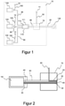
Figur 1 zeigt ein Blockschema stellvertretend für ein zentrales Heizsystem, das unter anderem das erfindungsgegenständliche Kombigerät enthält. -
Figur 2 zeigt einen Ausschnitt des Blockschemas im Querschnitt von vorne. -
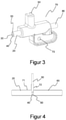
Figur 3 zeigt die perspektivische Ansicht des Trennblocks, der bei der Erfindung verwendet wird. -
Figur 4 zeigt einen Ausschnitt des Trennblocks im Querschnitt von vorne. - In dieser detaillierten Beschreibung wird das erfindungsgegenständliche Kombigerät zum besseren Verständnis anhand von Beispielen, die keine einschränkende Wirkung haben, beschrieben.
- Wie in
Figur 1 zu sehen ist, besitzt die erfindungsgegenständliche Kombitherme ein Metallgehäuse (10). Das betreffende Metallgehäuse (10) wurde mit einem Außengehäuse und einer Abdeckung (in der Figur nicht dargestellt) verschlossen. An dem Metallgehäuse (10), das eine Trägerfunktion übernimmt, befindet sich eine Steuereinheit als elektrische Hauptkomponente (110). Am Ausgang der Steuereinheit sind elektrische Zusatzkomponenten (120) wie Gebläse, Zünder oder Pumpe befestigt. Auf diese Weise steuert die Steuereinheit diese Komponenten. - Die Kombitherme bezieht die Energie, die sie für ihren Betrieb benötigt, aus dem Stromnetz (130), das Wechselstrom bereitstellt. Der Wechselstrom erreicht über ein Zuleitungskabel (20), das die Phasen-, Neutral- und Erdleitung (30, 40, 50) transportiert, die elektrische Hauptkomponente (110). Erfindungsgemäß ist zwischen der elektrischen Hauptkomponente (110) und dem Stromnetz (130) ein Trennblock (70) angeordnet.
- In
Figur 1 und 2 wird am betreffenden Trennblock (70) die Erdleitung (50) von den Phasen- und Neutralleitungen (30, 40) getrennt. Somit erreicht die Energie die elektrische Hauptkomponente (110) über ein Anschlusskabel (80), das nur die Phasen- und Neutralleitungen (30, 40) transportiert. Andererseits wird die Erdleitung (50) über das Metallgehäuse (10) mit einem Erdungspunkt (1) verbunden. - Die Erdleitung (50) erreicht den betreffenden Erdungspunkt (11) entlang einer Strecke, in deren Umgebung es kein Element gibt, das gegenüber hohen Temperaturen empfindlich ist.
- Der Stromanschluss der elektrischen Hauptkomponente (110), die vorzugsweise eine Steuereinheit ist, und der elektrischen Zusatzkomponenten (120) wird mit Zusatzanschlusskabeln (90) gewährleistet, die ebenso nur die Phasen- und Neutralleitungen transportieren. Die elektrischen Zusatzkomponenten (120) besitzen Zusatzerdleitungen (100), die mit den Zusatzerdungspunkten (12) am Metallgehäuse (10) verbunden sind und sich getrennt vom Zusatzanschlusskabel (90) erstrecken. In diesem Zusammenhang sind die Zusatzerdungspunkte (12) mit dem Erdungspunkt (11) über das Metallgehäuse (10) leitfähig verbunden. Andererseits werden auch die Strecken der Zusatzerdleitungen (100) so konfiguriert, dass es in ihrer näheren Umgebung kein Element gibt, das gegenüber hohen Temperaturen empfindlich ist.
- Wie in
Figur 3 und 4 zu sehen ist, befindet sich im erfindungsgegenständlichen Trennblock (70) eine Kabelführung (71) und eine Erdleitungsführung (72). Erfindungsgemäß erstreckt sich die Erdleitungsführung (72) vertikal zur Kabelführung (71). Andererseits besteht der Trennblock (70) aus zwei Teilen. Wenn diese beiden Teile miteinander verbunden werden, ist die betreffende Kabelführung (71) und Erdleitungsführung (72) definiert. - Dementsprechend wird bei dem Montageprozess zuerst der Mantel des Zuleitungskabels (20) ab einem bestimmten Punkt teilweise aufgeschnitten und die Erdungsleitung (50) über den Schnitt (60), der hier entstanden ist, herausgeholt. Auf diese Weise verwandelt sich der anschließende Abschnitt des Zuleitungskabels (20) in ein Anschlusskabel (80), das nur die Phasen- und Neutralleitungen (30, 40) transportiert. Das Kabel wird in dieser Form in den ersten Teil des Trennblocks (70) eingeführt und anschließend wird der zweite Teil des Trennblocks (70) an dem ersten Teil befestigt. Wenn das Kabel in den ersten Teil eingeführt wird, werden das Zuleitungskabel (20) und das Anschlusskabel (80) so angeordnet, dass sie sich entlang des Führungskabels (71) erstrecken, und die Erdleitung (50) wird so angeordnet, dass sie sich entlang der Erdleitungsführung (72) erstreckt.
- Zum Schluss wird der Trennblock (70) mit einem Metallanschlusselement (73) am Metallgehäuse (10) fixiert. Somit tritt das Zuleitungskabel (20), das an einem Ende des Trennblocks (70) eintritt und die Phasen-, Neutral- und Erdleitungen (30, 40, 50) transportiert, am anderen Ende als Anschlusskabel (80), das nur die Phasen- und Neutralleitungen (30, 40) transportiert, aus. Die Erdleitung (50) tritt in einer anderen Richtung, senkrecht zur Kabelführung, aus dem Trennblock (70) aus
- Bei einer vorzugsweisen Ausführung der Erfindung besteht der Trennblock (70) aus Kunststoff, der gegenüber hohen Temperaturen beständig ist, und besitzt dementsprechend die Brandklasse V0. Außerdem besitzt er eine wasserundurchlässige Struktur und eine Zugkraft von 100 N, was den Anforderungen der Norm EN 60335-1 entspricht.
- Somit stellen selbst hohe Temperaturen, die im Trennblock (70) insbesondere infolge eines Kurzschlusses der Erd- und Neutralleitung auftreten können, kein Risiko dar. Darüber hinaus wird verhindert, dass Flüssigkeit in den Trennblock (70) eindringt und zu Problemen wie Kurzschluss führt. Somit wird der Bereich, der die Erdleitung (50) von den anderen Leitungen trennt, dank des Trennblocks (70) vollkommen sicher verschlossen.
- Dank dieser Lösung erstrecken sich alle Erdleitungen im Metallgehäuse (10) der Kombitherme getrennt von den Phasen- und Neutralleitungen und verlaufen in ausreichender Entfernung zu allen Komponenten, die empfindlich gegenüber hohen Temperaturen sind. Außerdem kann auch über das Metallgehäuse eine effektive Erdung gewährleistet werden. Somit wurden alle Risiken eliminiert, die auftreten können, wenn in der Netzleitung die Neutral- oder Erdleitungen einen Kurzschluss verursachen.
-
- 10
- Metallgehäuse
- 11
- Erdungspunkt
- 12
- Zusatzerdungspunkt
- 20
- Zuleitungskabel
- 30
- Phasenleitung
- 40
- Neutralleitung
- 50
- Erdleitung
- 60
- Schnitt
- 70
- Trennblock
- 71
- Kabelführung
- 72
- Erdleitungsführung
- 73
- Anschlusselement
- 80
- Anschlusskabel
- 90
- Zusatzanschlusskabel
- 100
- Zusatzerdleitung
- 110
- Elektrische Hauptkomponente
- 111
- Temperaturempfindliches Teil
- 112
- Elektrisches Teil
- 120
- Elektrische Zusatzkomponente
- 130
- Stadtnetz
Claims (10)
- Wassererhitzer, insbesondere eine Kombitherme, der ein Metallgehäuse (10), mindestens einen Erdungspunkt (11), der leitfähig mit dem genannten Metallgehäuse (10) verbunden ist, ein Zuleitungskabel und eine elektrische Hauptkomponente (110) umfasst, die einen temperaturempfindlichen Teil (111) und einen elektrischen Teil (112) besitzt, der ausgelegt ist mithilfe des Zuleitungskabels (20), das eine Phasenleitung (30), eine Neutralleitung (40) und eine Erdleitung (50) transportiert, mit einem Stromnetz (130) verbunden zu werden, wobei die genannte Erdleitung (50) von den Phasen- und Neutralleitungen (30, 40) getrennt wurde, bevor sie die genannte elektrische Hauptkomponente (110) erreicht, und die mit dem genannten Erdungspunkt (11) verbunden ist, wobei ein Trennblock (70) die Erdleitung (50) von den Phasen- und Neutralleitungen (30, 40) trennt, wobei der genannte Trennblock (70) an dem Metallgehäuse befestigt wird,dadurch gekennzeichnet, dass der Trennblock (70) eine Kabelführung (71) und eine Erdleitungsführung umfasst, und sich die Erdleitungsführung (72) vertikal zur Kabelführung (71) erstreckt,wobei der Trennblock (70) aus zwei Teilen besteht, die miteinander verbunden die betreffende Kabelführung (71) und Erdleitungsführung (72) definieren,wobei das Zuleitungskabel (20), das an einem Ende des Trennblocks (70) eintritt und die Phasen-, Neutral- und Erdleitungen (30, 40, 50) transportiert, am anderen Ende als Anschlusskabel (80), das nur die Phasen- und Neutralleitungen (30, 40) transportiert, austritt,wobei die Erdleitung (50) in einer anderen Richtung aus dem Trennblock (70) austritt.
- Wassererhitzer nach Anspruch 1, bei welchem sich die Erdleitung (50) entlang einer Strecke, in deren Umgebung es keine temperaturempfindlichen Elemente gibt, auf dem Metallgehäuse (10) erstreckt.
- Wassererhitzer nach Anspruch 1, bei welchem ein Anschlusskabel (80) die Phasen- und Neutralleitungen (30, 40) zur elektrischen Hauptkomponente (110) transportiert.
- Wassererhitzer nach Anspruch 1, bei welchem die Kabelführung (71) so konfiguriert wurde, dass sie das Zuleitungs- und Anschlusskabel (20, 80) aufnimmt, und die Erdleitungsführung (72)so konfiguriert wurde, dass sie die getrennte Erdleitung (50) aufnimmt.
- Wassererhitzer nach Anspruch 1, bei welchem der Trennblock (70) aus nicht brennbarem Kunststoff besteht.
- Wassererhitzer nach einem der vorhergehenden Ansprüche, bei welchem die elektrische Hauptkomponente (110) eine Steuereinheit ist.
- Wassererhitzer nach einem der vorhergehenden Ansprüche, bei welchem ein Zusatzanschlusskabel (90) nur die Phasen- und Neutralleitungen (30, 40) transportiert und sich zwischen der elektrischen Hauptkomponente (110) und einer elektrischen Zusatzkomponente (120) erstreckt.
- Wassererhitzer nach Anspruch 7, bei welchem die genannte elektrische Zusatzkomponente (120) mithilfe einer Zusatzerdungsleitung (110) geerdet wird, die mit einem Zusatzerdungspunkt (12) verbunden ist, der leitfähig mit dem Erdungspunkt (11) in Kontakt steht.
- Wassererhitzer nach Anspruch 8, bei welchem die elektrische Zusatzkomponente (120) ein Gebläse, ein Zünder oder eine Pumpe ist.
- Wassererhitzer nach einem der vorhergehenden Ansprüche, bei welchem die genannten temperaturempfindlichen Teile (111) aus Kunststoff bestehen.
Applications Claiming Priority (1)
| Application Number | Priority Date | Filing Date | Title |
|---|---|---|---|
| TR2017/15030A TR201715030A2 (tr) | 2017-10-05 | 2017-10-05 | İyi̇leşti̇ri̇lmi̇ş topraklama özelli̇ği̇ne sahi̇p bi̇r su isitici |
Publications (2)
| Publication Number | Publication Date |
|---|---|
| EP3467396A1 EP3467396A1 (de) | 2019-04-10 |
| EP3467396B1 true EP3467396B1 (de) | 2022-03-16 |
Family
ID=63685877
Family Applications (1)
| Application Number | Title | Priority Date | Filing Date |
|---|---|---|---|
| EP18197188.8A Active EP3467396B1 (de) | 2017-10-05 | 2018-09-27 | Wassererhitzer mit verbesserter erdungseigenschaft |
Country Status (4)
| Country | Link |
|---|---|
| EP (1) | EP3467396B1 (de) |
| PL (1) | PL3467396T3 (de) |
| PT (1) | PT3467396T (de) |
| TR (1) | TR201715030A2 (de) |
Citations (1)
| Publication number | Priority date | Publication date | Assignee | Title |
|---|---|---|---|---|
| CN2483657Y (zh) * | 2001-02-19 | 2002-03-27 | 钟知勉 | 一种贮水式电热水器 |
Family Cites Families (5)
| Publication number | Priority date | Publication date | Assignee | Title |
|---|---|---|---|---|
| JP2003052540A (ja) * | 2001-08-08 | 2003-02-25 | Matsushita Electric Ind Co Ltd | 電気湯沸かし器 |
| CN102340065B (zh) | 2010-07-16 | 2014-07-02 | 富士康(昆山)电脑接插件有限公司 | 插头连接器组件 |
| US9234678B1 (en) * | 2011-09-27 | 2016-01-12 | Rheem Manufacturing Company | Stackable water heater apparatus |
| KR20130074890A (ko) * | 2011-12-27 | 2013-07-05 | 황보기만 | 도전성호스관발열체와 이를 이용한 축열탱크보일러 냉온수통 |
| CN203826665U (zh) | 2014-04-03 | 2014-09-10 | 广东华声电器股份有限公司 | 一种加强型插头内架 |
-
2017
- 2017-10-05 TR TR2017/15030A patent/TR201715030A2/tr unknown
-
2018
- 2018-09-27 PT PT181971888T patent/PT3467396T/pt unknown
- 2018-09-27 EP EP18197188.8A patent/EP3467396B1/de active Active
- 2018-09-27 PL PL18197188.8T patent/PL3467396T3/pl unknown
Patent Citations (1)
| Publication number | Priority date | Publication date | Assignee | Title |
|---|---|---|---|---|
| CN2483657Y (zh) * | 2001-02-19 | 2002-03-27 | 钟知勉 | 一种贮水式电热水器 |
Also Published As
| Publication number | Publication date |
|---|---|
| EP3467396A1 (de) | 2019-04-10 |
| TR201715030A2 (tr) | 2019-04-22 |
| PL3467396T3 (pl) | 2022-08-01 |
| PT3467396T (pt) | 2022-04-06 |
Similar Documents
| Publication | Publication Date | Title |
|---|---|---|
| DE10245808B4 (de) | Verfahren zum Herstellen einer elektromagnetischen Abschirmungsstruktur und elektromagnetische Abschirmungsstruktur für elektrische Drähte | |
| DE19740224B4 (de) | Drehbare Verbindungsvorrichtung zur Verbindung von Kabeln | |
| DE1130052B (de) | Selbsttaetige Sicherung zum Schutz elektrischer Verbraucher | |
| WO2010091445A1 (de) | Halterung für einen wechselrichter und verfahren zur montage eines wechselrichters | |
| EP3073176B1 (de) | Elektrische anschlussanordnung für leuchten | |
| EP3176878B1 (de) | Kabelanschlusskasten und überspannungsschutzmodul für einen kabelanschlusskasten | |
| DE102013016099A1 (de) | Mehrfachanschlusskabel zur Verbindung von Hochspannungsvorrichtungen eines Kraftfahrzeugs und Kraftfahrzeug | |
| DE602005005147T2 (de) | Heizkabel | |
| EP0024022A1 (de) | Installationssystem | |
| EP3467396A1 (de) | Wassererhitzer mit verbesserter erdungseigenschaft | |
| EP0397063A2 (de) | Einrichtung zum Schutz elektrischer Anlagen | |
| EP2982013B1 (de) | Schaltschrankanordnung mit verbundenen schutzbereichen | |
| DE102011121990B4 (de) | Photovoltaikanlage und Verbindungsleitung zum Anschluss eines Photvoltaikmoduls | |
| DE20315440U1 (de) | Thermopaar für Elektroventile von Gasbrennern | |
| CH712682B1 (de) | System von elektrischen Installationsgeräten. | |
| DE102015001890B4 (de) | Notleuchte | |
| DE4338699C1 (de) | Heizband-Steckverbinder | |
| EP0896409A2 (de) | Abzweigmuffe für Energiekabel | |
| DE9418646U1 (de) | Heizleitungseinrichtung, insbesondere zum Einsatz in explosionsgefährdeter Umgebung | |
| DE102004017336B4 (de) | Steckdosenleiste | |
| DE456697C (de) | Sicherheitsschaltung fuer Stromverteilungsanlagen | |
| DE102016117397A1 (de) | Sicherungsanordnung zur absicherung von aussenleitern einer elektrischen sicherungseinheit zur bildung eines gebäudeanschlusses | |
| WO2022167493A1 (de) | Leitungsanordnung für ein gleichspannungs-bordnetz eines kraftfahrzeuges | |
| DE416300C (de) | Elektrischer Fliegenfaenger | |
| DE4307355C2 (de) | Elektrisch beheizter Wassererhitzer, insbesondere Durchlauferhitzer |
Legal Events
| Date | Code | Title | Description |
|---|---|---|---|
| PUAI | Public reference made under article 153(3) epc to a published international application that has entered the european phase |
Free format text: ORIGINAL CODE: 0009012 |
|
| STAA | Information on the status of an ep patent application or granted ep patent |
Free format text: STATUS: THE APPLICATION HAS BEEN PUBLISHED |
|
| AK | Designated contracting states |
Kind code of ref document: A1 Designated state(s): AL AT BE BG CH CY CZ DE DK EE ES FI FR GB GR HR HU IE IS IT LI LT LU LV MC MK MT NL NO PL PT RO RS SE SI SK SM TR |
|
| AX | Request for extension of the european patent |
Extension state: BA ME |
|
| STAA | Information on the status of an ep patent application or granted ep patent |
Free format text: STATUS: REQUEST FOR EXAMINATION WAS MADE |
|
| 17P | Request for examination filed |
Effective date: 20191010 |
|
| RBV | Designated contracting states (corrected) |
Designated state(s): AL AT BE BG CH CY CZ DE DK EE ES FI FR GB GR HR HU IE IS IT LI LT LU LV MC MK MT NL NO PL PT RO RS SE SI SK SM TR |
|
| STAA | Information on the status of an ep patent application or granted ep patent |
Free format text: STATUS: EXAMINATION IS IN PROGRESS |
|
| 17Q | First examination report despatched |
Effective date: 20200124 |
|
| REG | Reference to a national code |
Ref country code: DE Ref legal event code: R079 Ref document number: 502018009094 Country of ref document: DE Free format text: PREVIOUS MAIN CLASS: F24H0001000000 Ipc: F24H0009200000 |
|
| RIC1 | Information provided on ipc code assigned before grant |
Ipc: F24H 9/02 20060101ALI20210810BHEP Ipc: F24H 9/20 20060101AFI20210810BHEP |
|
| GRAP | Despatch of communication of intention to grant a patent |
Free format text: ORIGINAL CODE: EPIDOSNIGR1 |
|
| STAA | Information on the status of an ep patent application or granted ep patent |
Free format text: STATUS: GRANT OF PATENT IS INTENDED |
|
| INTG | Intention to grant announced |
Effective date: 20211004 |
|
| RAP3 | Party data changed (applicant data changed or rights of an application transferred) |
Owner name: BOSCH TERMOTEKNIK ISITMA VE KLIMA SANAYI TICARET ANONIM SIRKETI |
|
| GRAS | Grant fee paid |
Free format text: ORIGINAL CODE: EPIDOSNIGR3 |
|
| GRAA | (expected) grant |
Free format text: ORIGINAL CODE: 0009210 |
|
| STAA | Information on the status of an ep patent application or granted ep patent |
Free format text: STATUS: THE PATENT HAS BEEN GRANTED |
|
| AK | Designated contracting states |
Kind code of ref document: B1 Designated state(s): AL AT BE BG CH CY CZ DE DK EE ES FI FR GB GR HR HU IE IS IT LI LT LU LV MC MK MT NL NO PL PT RO RS SE SI SK SM TR |
|
| REG | Reference to a national code |
Ref country code: GB Ref legal event code: FG4D Free format text: NOT ENGLISH |
|
| REG | Reference to a national code |
Ref country code: CH Ref legal event code: EP |
|
| REG | Reference to a national code |
Ref country code: PT Ref legal event code: SC4A Ref document number: 3467396 Country of ref document: PT Date of ref document: 20220406 Kind code of ref document: T Free format text: AVAILABILITY OF NATIONAL TRANSLATION Effective date: 20220331 |
|
| REG | Reference to a national code |
Ref country code: DE Ref legal event code: R096 Ref document number: 502018009094 Country of ref document: DE |
|
| REG | Reference to a national code |
Ref country code: IE Ref legal event code: FG4D Free format text: LANGUAGE OF EP DOCUMENT: GERMAN |
|
| REG | Reference to a national code |
Ref country code: AT Ref legal event code: REF Ref document number: 1476160 Country of ref document: AT Kind code of ref document: T Effective date: 20220415 |
|
| REG | Reference to a national code |
Ref country code: LT Ref legal event code: MG9D |
|
| REG | Reference to a national code |
Ref country code: NL Ref legal event code: MP Effective date: 20220316 |
|
| PG25 | Lapsed in a contracting state [announced via postgrant information from national office to epo] |
Ref country code: SE Free format text: LAPSE BECAUSE OF FAILURE TO SUBMIT A TRANSLATION OF THE DESCRIPTION OR TO PAY THE FEE WITHIN THE PRESCRIBED TIME-LIMIT Effective date: 20220316 Ref country code: RS Free format text: LAPSE BECAUSE OF FAILURE TO SUBMIT A TRANSLATION OF THE DESCRIPTION OR TO PAY THE FEE WITHIN THE PRESCRIBED TIME-LIMIT Effective date: 20220316 Ref country code: NO Free format text: LAPSE BECAUSE OF FAILURE TO SUBMIT A TRANSLATION OF THE DESCRIPTION OR TO PAY THE FEE WITHIN THE PRESCRIBED TIME-LIMIT Effective date: 20220616 Ref country code: LT Free format text: LAPSE BECAUSE OF FAILURE TO SUBMIT A TRANSLATION OF THE DESCRIPTION OR TO PAY THE FEE WITHIN THE PRESCRIBED TIME-LIMIT Effective date: 20220316 Ref country code: HR Free format text: LAPSE BECAUSE OF FAILURE TO SUBMIT A TRANSLATION OF THE DESCRIPTION OR TO PAY THE FEE WITHIN THE PRESCRIBED TIME-LIMIT Effective date: 20220316 Ref country code: BG Free format text: LAPSE BECAUSE OF FAILURE TO SUBMIT A TRANSLATION OF THE DESCRIPTION OR TO PAY THE FEE WITHIN THE PRESCRIBED TIME-LIMIT Effective date: 20220616 |
|
| PG25 | Lapsed in a contracting state [announced via postgrant information from national office to epo] |
Ref country code: LV Free format text: LAPSE BECAUSE OF FAILURE TO SUBMIT A TRANSLATION OF THE DESCRIPTION OR TO PAY THE FEE WITHIN THE PRESCRIBED TIME-LIMIT Effective date: 20220316 Ref country code: GR Free format text: LAPSE BECAUSE OF FAILURE TO SUBMIT A TRANSLATION OF THE DESCRIPTION OR TO PAY THE FEE WITHIN THE PRESCRIBED TIME-LIMIT Effective date: 20220617 Ref country code: FI Free format text: LAPSE BECAUSE OF FAILURE TO SUBMIT A TRANSLATION OF THE DESCRIPTION OR TO PAY THE FEE WITHIN THE PRESCRIBED TIME-LIMIT Effective date: 20220316 |
|
| PG25 | Lapsed in a contracting state [announced via postgrant information from national office to epo] |
Ref country code: NL Free format text: LAPSE BECAUSE OF FAILURE TO SUBMIT A TRANSLATION OF THE DESCRIPTION OR TO PAY THE FEE WITHIN THE PRESCRIBED TIME-LIMIT Effective date: 20220316 |
|
| PG25 | Lapsed in a contracting state [announced via postgrant information from national office to epo] |
Ref country code: SM Free format text: LAPSE BECAUSE OF FAILURE TO SUBMIT A TRANSLATION OF THE DESCRIPTION OR TO PAY THE FEE WITHIN THE PRESCRIBED TIME-LIMIT Effective date: 20220316 Ref country code: SK Free format text: LAPSE BECAUSE OF FAILURE TO SUBMIT A TRANSLATION OF THE DESCRIPTION OR TO PAY THE FEE WITHIN THE PRESCRIBED TIME-LIMIT Effective date: 20220316 Ref country code: RO Free format text: LAPSE BECAUSE OF FAILURE TO SUBMIT A TRANSLATION OF THE DESCRIPTION OR TO PAY THE FEE WITHIN THE PRESCRIBED TIME-LIMIT Effective date: 20220316 Ref country code: ES Free format text: LAPSE BECAUSE OF FAILURE TO SUBMIT A TRANSLATION OF THE DESCRIPTION OR TO PAY THE FEE WITHIN THE PRESCRIBED TIME-LIMIT Effective date: 20220316 Ref country code: EE Free format text: LAPSE BECAUSE OF FAILURE TO SUBMIT A TRANSLATION OF THE DESCRIPTION OR TO PAY THE FEE WITHIN THE PRESCRIBED TIME-LIMIT Effective date: 20220316 Ref country code: CZ Free format text: LAPSE BECAUSE OF FAILURE TO SUBMIT A TRANSLATION OF THE DESCRIPTION OR TO PAY THE FEE WITHIN THE PRESCRIBED TIME-LIMIT Effective date: 20220316 |
|
| PG25 | Lapsed in a contracting state [announced via postgrant information from national office to epo] |
Ref country code: IS Free format text: LAPSE BECAUSE OF FAILURE TO SUBMIT A TRANSLATION OF THE DESCRIPTION OR TO PAY THE FEE WITHIN THE PRESCRIBED TIME-LIMIT Effective date: 20220716 Ref country code: AL Free format text: LAPSE BECAUSE OF FAILURE TO SUBMIT A TRANSLATION OF THE DESCRIPTION OR TO PAY THE FEE WITHIN THE PRESCRIBED TIME-LIMIT Effective date: 20220316 |
|
| REG | Reference to a national code |
Ref country code: DE Ref legal event code: R097 Ref document number: 502018009094 Country of ref document: DE |
|
| PLBE | No opposition filed within time limit |
Free format text: ORIGINAL CODE: 0009261 |
|
| STAA | Information on the status of an ep patent application or granted ep patent |
Free format text: STATUS: NO OPPOSITION FILED WITHIN TIME LIMIT |
|
| PG25 | Lapsed in a contracting state [announced via postgrant information from national office to epo] |
Ref country code: DK Free format text: LAPSE BECAUSE OF FAILURE TO SUBMIT A TRANSLATION OF THE DESCRIPTION OR TO PAY THE FEE WITHIN THE PRESCRIBED TIME-LIMIT Effective date: 20220316 |
|
| 26N | No opposition filed |
Effective date: 20221219 |
|
| PG25 | Lapsed in a contracting state [announced via postgrant information from national office to epo] |
Ref country code: SI Free format text: LAPSE BECAUSE OF FAILURE TO SUBMIT A TRANSLATION OF THE DESCRIPTION OR TO PAY THE FEE WITHIN THE PRESCRIBED TIME-LIMIT Effective date: 20220316 |
|
| PG25 | Lapsed in a contracting state [announced via postgrant information from national office to epo] |
Ref country code: MC Free format text: LAPSE BECAUSE OF FAILURE TO SUBMIT A TRANSLATION OF THE DESCRIPTION OR TO PAY THE FEE WITHIN THE PRESCRIBED TIME-LIMIT Effective date: 20220316 |
|
| REG | Reference to a national code |
Ref country code: CH Ref legal event code: PL |
|
| REG | Reference to a national code |
Ref country code: BE Ref legal event code: MM Effective date: 20220930 |
|
| PG25 | Lapsed in a contracting state [announced via postgrant information from national office to epo] |
Ref country code: LU Free format text: LAPSE BECAUSE OF NON-PAYMENT OF DUE FEES Effective date: 20220927 |
|
| PG25 | Lapsed in a contracting state [announced via postgrant information from national office to epo] |
Ref country code: LI Free format text: LAPSE BECAUSE OF NON-PAYMENT OF DUE FEES Effective date: 20220930 Ref country code: IE Free format text: LAPSE BECAUSE OF NON-PAYMENT OF DUE FEES Effective date: 20220927 Ref country code: FR Free format text: LAPSE BECAUSE OF NON-PAYMENT OF DUE FEES Effective date: 20220930 Ref country code: CH Free format text: LAPSE BECAUSE OF NON-PAYMENT OF DUE FEES Effective date: 20220930 |
|
| PG25 | Lapsed in a contracting state [announced via postgrant information from national office to epo] |
Ref country code: BE Free format text: LAPSE BECAUSE OF NON-PAYMENT OF DUE FEES Effective date: 20220930 |
|
| PG25 | Lapsed in a contracting state [announced via postgrant information from national office to epo] |
Ref country code: HU Free format text: LAPSE BECAUSE OF FAILURE TO SUBMIT A TRANSLATION OF THE DESCRIPTION OR TO PAY THE FEE WITHIN THE PRESCRIBED TIME-LIMIT; INVALID AB INITIO Effective date: 20180927 |
|
| PG25 | Lapsed in a contracting state [announced via postgrant information from national office to epo] |
Ref country code: CY Free format text: LAPSE BECAUSE OF FAILURE TO SUBMIT A TRANSLATION OF THE DESCRIPTION OR TO PAY THE FEE WITHIN THE PRESCRIBED TIME-LIMIT Effective date: 20220316 |
|
| PG25 | Lapsed in a contracting state [announced via postgrant information from national office to epo] |
Ref country code: MK Free format text: LAPSE BECAUSE OF FAILURE TO SUBMIT A TRANSLATION OF THE DESCRIPTION OR TO PAY THE FEE WITHIN THE PRESCRIBED TIME-LIMIT Effective date: 20220316 |
|
| PG25 | Lapsed in a contracting state [announced via postgrant information from national office to epo] |
Ref country code: MT Free format text: LAPSE BECAUSE OF FAILURE TO SUBMIT A TRANSLATION OF THE DESCRIPTION OR TO PAY THE FEE WITHIN THE PRESCRIBED TIME-LIMIT Effective date: 20220316 |
|
| REG | Reference to a national code |
Ref country code: AT Ref legal event code: MM01 Ref document number: 1476160 Country of ref document: AT Kind code of ref document: T Effective date: 20230927 |
|
| PG25 | Lapsed in a contracting state [announced via postgrant information from national office to epo] |
Ref country code: AT Free format text: LAPSE BECAUSE OF NON-PAYMENT OF DUE FEES Effective date: 20230927 |
|
| PG25 | Lapsed in a contracting state [announced via postgrant information from national office to epo] |
Ref country code: AT Free format text: LAPSE BECAUSE OF NON-PAYMENT OF DUE FEES Effective date: 20230927 |
|
| PGFP | Annual fee paid to national office [announced via postgrant information from national office to epo] |
Ref country code: PT Payment date: 20250912 Year of fee payment: 8 |
|
| PGFP | Annual fee paid to national office [announced via postgrant information from national office to epo] |
Ref country code: PL Payment date: 20250915 Year of fee payment: 8 Ref country code: TR Payment date: 20250918 Year of fee payment: 8 |
|
| PGFP | Annual fee paid to national office [announced via postgrant information from national office to epo] |
Ref country code: GB Payment date: 20250923 Year of fee payment: 8 |
|
| PGFP | Annual fee paid to national office [announced via postgrant information from national office to epo] |
Ref country code: DE Payment date: 20251121 Year of fee payment: 8 |
|
| PGFP | Annual fee paid to national office [announced via postgrant information from national office to epo] |
Ref country code: IT Payment date: 20250930 Year of fee payment: 8 |
|
| PGFP | Annual fee paid to national office [announced via postgrant information from national office to epo] |
Ref country code: AT Payment date: 20260410 Year of fee payment: 5 |