EP3467287B1 - Cylinder liner assembly for engine - Google Patents
Cylinder liner assembly for engine Download PDFInfo
- Publication number
- EP3467287B1 EP3467287B1 EP18197805.7A EP18197805A EP3467287B1 EP 3467287 B1 EP3467287 B1 EP 3467287B1 EP 18197805 A EP18197805 A EP 18197805A EP 3467287 B1 EP3467287 B1 EP 3467287B1
- Authority
- EP
- European Patent Office
- Prior art keywords
- cylinder liner
- engine
- cylinder
- liners
- support plate
- Prior art date
- Legal status (The legal status is an assumption and is not a legal conclusion. Google has not performed a legal analysis and makes no representation as to the accuracy of the status listed.)
- Active
Links
Images




Classifications
-
- F—MECHANICAL ENGINEERING; LIGHTING; HEATING; WEAPONS; BLASTING
- F02—COMBUSTION ENGINES; HOT-GAS OR COMBUSTION-PRODUCT ENGINE PLANTS
- F02F—CYLINDERS, PISTONS OR CASINGS, FOR COMBUSTION ENGINES; ARRANGEMENTS OF SEALINGS IN COMBUSTION ENGINES
- F02F1/00—Cylinders; Cylinder heads
- F02F1/004—Cylinder liners
-
- F—MECHANICAL ENGINEERING; LIGHTING; HEATING; WEAPONS; BLASTING
- F02—COMBUSTION ENGINES; HOT-GAS OR COMBUSTION-PRODUCT ENGINE PLANTS
- F02F—CYLINDERS, PISTONS OR CASINGS, FOR COMBUSTION ENGINES; ARRANGEMENTS OF SEALINGS IN COMBUSTION ENGINES
- F02F1/00—Cylinders; Cylinder heads
- F02F1/02—Cylinders; Cylinder heads having cooling means
- F02F1/10—Cylinders; Cylinder heads having cooling means for liquid cooling
- F02F1/102—Attachment of cylinders to crankcase
-
- F—MECHANICAL ENGINEERING; LIGHTING; HEATING; WEAPONS; BLASTING
- F02—COMBUSTION ENGINES; HOT-GAS OR COMBUSTION-PRODUCT ENGINE PLANTS
- F02B—INTERNAL-COMBUSTION PISTON ENGINES; COMBUSTION ENGINES IN GENERAL
- F02B75/00—Other engines
- F02B75/16—Engines characterised by number of cylinders, e.g. single-cylinder engines
- F02B75/18—Multi-cylinder engines
- F02B75/22—Multi-cylinder engines with cylinders in V, fan, or star arrangement
-
- F—MECHANICAL ENGINEERING; LIGHTING; HEATING; WEAPONS; BLASTING
- F02—COMBUSTION ENGINES; HOT-GAS OR COMBUSTION-PRODUCT ENGINE PLANTS
- F02F—CYLINDERS, PISTONS OR CASINGS, FOR COMBUSTION ENGINES; ARRANGEMENTS OF SEALINGS IN COMBUSTION ENGINES
- F02F1/00—Cylinders; Cylinder heads
- F02F1/02—Cylinders; Cylinder heads having cooling means
- F02F1/10—Cylinders; Cylinder heads having cooling means for liquid cooling
- F02F1/16—Cylinder liners of wet type
-
- F—MECHANICAL ENGINEERING; LIGHTING; HEATING; WEAPONS; BLASTING
- F02—COMBUSTION ENGINES; HOT-GAS OR COMBUSTION-PRODUCT ENGINE PLANTS
- F02F—CYLINDERS, PISTONS OR CASINGS, FOR COMBUSTION ENGINES; ARRANGEMENTS OF SEALINGS IN COMBUSTION ENGINES
- F02F7/00—Casings, e.g. crankcases
- F02F7/0002—Cylinder arrangements
- F02F7/0012—Crankcases of V-engines
-
- F—MECHANICAL ENGINEERING; LIGHTING; HEATING; WEAPONS; BLASTING
- F02—COMBUSTION ENGINES; HOT-GAS OR COMBUSTION-PRODUCT ENGINE PLANTS
- F02B—INTERNAL-COMBUSTION PISTON ENGINES; COMBUSTION ENGINES IN GENERAL
- F02B75/00—Other engines
- F02B75/16—Engines characterised by number of cylinders, e.g. single-cylinder engines
- F02B75/18—Multi-cylinder engines
- F02B2075/1804—Number of cylinders
- F02B2075/1832—Number of cylinders eight
-
- F—MECHANICAL ENGINEERING; LIGHTING; HEATING; WEAPONS; BLASTING
- F02—COMBUSTION ENGINES; HOT-GAS OR COMBUSTION-PRODUCT ENGINE PLANTS
- F02B—INTERNAL-COMBUSTION PISTON ENGINES; COMBUSTION ENGINES IN GENERAL
- F02B75/00—Other engines
- F02B75/16—Engines characterised by number of cylinders, e.g. single-cylinder engines
- F02B75/18—Multi-cylinder engines
- F02B2075/1804—Number of cylinders
- F02B2075/184—Number of cylinders ten
-
- F—MECHANICAL ENGINEERING; LIGHTING; HEATING; WEAPONS; BLASTING
- F02—COMBUSTION ENGINES; HOT-GAS OR COMBUSTION-PRODUCT ENGINE PLANTS
- F02B—INTERNAL-COMBUSTION PISTON ENGINES; COMBUSTION ENGINES IN GENERAL
- F02B75/00—Other engines
- F02B75/16—Engines characterised by number of cylinders, e.g. single-cylinder engines
- F02B75/18—Multi-cylinder engines
- F02B2075/1804—Number of cylinders
- F02B2075/1848—Number of cylinders twelve
-
- F—MECHANICAL ENGINEERING; LIGHTING; HEATING; WEAPONS; BLASTING
- F02—COMBUSTION ENGINES; HOT-GAS OR COMBUSTION-PRODUCT ENGINE PLANTS
- F02B—INTERNAL-COMBUSTION PISTON ENGINES; COMBUSTION ENGINES IN GENERAL
- F02B75/00—Other engines
- F02B75/16—Engines characterised by number of cylinders, e.g. single-cylinder engines
- F02B75/18—Multi-cylinder engines
- F02B2075/1804—Number of cylinders
- F02B2075/1864—Number of cylinders sixteen
-
- F—MECHANICAL ENGINEERING; LIGHTING; HEATING; WEAPONS; BLASTING
- F02—COMBUSTION ENGINES; HOT-GAS OR COMBUSTION-PRODUCT ENGINE PLANTS
- F02B—INTERNAL-COMBUSTION PISTON ENGINES; COMBUSTION ENGINES IN GENERAL
- F02B75/00—Other engines
- F02B75/16—Engines characterised by number of cylinders, e.g. single-cylinder engines
- F02B75/18—Multi-cylinder engines
- F02B2075/1804—Number of cylinders
- F02B2075/1868—Number of cylinders twenty
Definitions
- the present disclosure relates to an engine, and more particularly to a cylinder liner assembly of the engine.
- Engines such as multi-cylinder engines, are generally subjected to stresses during an operation of the engine. Such stresses may cause corrosion, and eventually, failure of engine components, such as an engine block, cylinder liners, cylinder liner support, and the like.
- engine components such as an engine block, cylinder liners, cylinder liner support, and the like.
- some engines include individual cylinder liner support that have ribs or web to interconnect adjacent cylinder liners. The ribs or webs are subjected to non-uniform stresses distribution (stiffness). This non-uniform stress distribution may cause corrosion of the cylinder liner support, which is not desirable.
- U.S. Patent Number 2,817,327 describes an engine block construction utilizing wet cylinder liners, which simplifies the cylinder block casting.
- the casting can be made merely in a box-like form so that when the liners with their top plate are in position, a coolant space is provided between the liners and the side and end walls of the block casting.
- the construction requires a minimum of space between the respective cylinders since no part of the cylinder block is located between the liners.
- the liner assembly comprising the plate and the liners is replaceable as a single unit and because of its rigidity the effect of the stresses resulting from securing the cylinder head to the block is minimized.
- the construction also provides wide choice for the location of the studs for securing the head to the block and the plate provides a metal coolant seal.
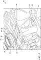
- FIG. 1 is a perspective view of an exemplary engine 100.
- the engine 100 is embodied as an internal combustion engine, and more particularly a reciprocating piston engine. Further, the engine 100 may include any one of a spark ignition engine or a compression ignition engine, such as a diesel engine, a natural gas engine, a homogeneous charge compression ignition engine, a reactivity controlled compression ignition engine, or any other engine known in the art.
- the engine 100 may be fueled by one or a combination of gasoline, diesel fuel, biodiesel, dimethyl ether, alcohol, natural gas, propane, or any other combustion fuel known in the art.
- the concepts of the present disclosure may be suitably applicable to any type and configuration of the engine 100.
- the engine 100 may be mounted on a machine (not shown).
- the engine 100 and/or the machine may be used for applications including, but not limited to, power generation, transportation, construction, agriculture, forestry, aviation, marine, material handling, and waste management.
- the engine 100 is according to the invention in the form of a multi-cylinder engine.
- the engine 100 includes an engine block 102.
- the engine 100 also includes a cylinder head 104 mounted on the engine block 102.
- the cylinder head 104 may house one or more components and/or systems (not shown) of the engine 100 such as a valve train, an intake manifold, an exhaust manifold, sensors, and so on.
- the engine 100 may include various other components and/or systems (not shown) such as a crankcase, a fuel system, an air system, a cooling system, a turbocharger, an exhaust gas recirculation system, an exhaust gas aftertreatment system, and so on.
- a number of cylinders 106 are disposed within the engine block 102.
- the engine 100 further includes a piston (not shown) movably disposed within each of the cylinders 106.
- Each of the pistons may be coupled to a crankshaft (not shown) of the engine 100. Energy generated from combustion of the fuel inside the cylinders 106 may be converted to rotational energy of the crankshaft by the pistons.
- the cylinders 106 may be arranged in any configuration such as inline, radial, "V", and so on.
- the engine 100 includes a first bank of cylinders 108 provided at a first side 109 of the engine 100. Further, the engine 100 includes a second bank of cylinders 110 provided at a second side 111 of the engine 100. As shown, the first and second bank of cylinders 108, 110 include the cylinders 106. The first bank of cylinders 108 includes six cylinders 106. Similarly, the second bank of cylinders 110 includes six cylinders 106.
- the engine 100 may alternatively include 8 cylinders, 10 cylinders, 16 cylinders, or 20 cylinders, based on system requirements.
- the engine block 102 includes a block 112.
- the block 112 has a generally rectangular box shaped structure having side walls 114 and end walls 116.
- the present disclosure will now be explained in relation to components provided at the first side 109 of the engine 100. However, it should be noted that the details provided below are equally applicable to components provided at the second side 111 of the engine 100.
- a cylinder liner assembly 118 is disposed in the block 112.
- the cylinder liner assembly 118 includes a number of cylinder liners 120 that are received within the engine block 102 and the cylinder head 104 (see FIG. 1 ) closes off an upper end 122 (shown in FIG. 3 ) of the cylinder liners 120.
- the cylinder liners 120 define an inner wall of the cylinders 106. Further, the cylinder liners 120 extend along an axis X-X' (shown in FIG. 4 ). Further, a cylinder liner room 124 (shown in FIG. 4 ) is defined between the respective cylinder liners 120 and the engine block 102.
- the cylinder liner assembly 118 is secured at a top portion of the engine block 102 by being clamped between the block 112 and the cylinder head 104.
- the cylinder head 104 may be secured to the block 112 in the usual manner, that is, by the use of studs threaded into the block 112.
- the cylinder liner assembly 118 also includes a mounting structure 126 attached to the engine block 102.
- the mounting structure 126 is integrally formed with the engine block 102.
- the mounting structure 126 couples the number of cylinder liners 120 to the engine block 102.
- the cylinder liners 120 rest on the mounting structure 126 and are secured thereto.
- the mounting structure 126 includes a first cylinder liner support plate 128.
- the first cylinder liner support plate 128 defines a number of equally spaced apart first cylinder liner receiving openings 130, only one of which is shown in the accompanying figure.
- the first cylinder liner support plate 128 extends along a length "L" (shown in FIG. 2 ) of the engine block 102.
- a second cylinder liner support plate 132 defines a number of equally spaced apart second cylinder liner receiving openings 134.
- the second cylinder liner support plate 132 extends along the length "L" of the engine block 102. It should be noted that the cylinder liners 120 are received within the respective first and second cylinder liner receiving openings 130, 134.
- the mounting structure 126 includes a number of first cylinder liner radial guides 138 and a number of second cylinder liner radial guides 140.
- the first cylinder liner radial guides 138 are defined in the first cylinder liner support plate 128.
- the second cylinder liner radial guides 140 are defined in the second cylinder liner support plate 132.
- the first and second cylinder liner radial guides 138, 140 support the cylinder liners 120 within the engine block 102.
- the first and second cylinder liner radial guides 138, 140 are spaced apart from each other along the axis X-X' (see FIG. 4 ).
- each cylinder liner 120 includes a flange portion 142.
- the flange portion 142 includes a surface 144 that rests on the first cylinder liner support plate 128. Further, the flange portion 142 extends above the first cylinder liner support plate 128 along the axis X-X' defined by the cylinder liners 120, when the cylinder liner 120 is received within the engine block 102. It should be noted that the cylinder liners 120 at their upper and lower ends 122, 136 are rigidly secured to the first and second cylinder liner support plates 128, 132, respectively.
- Any suitable means may be provided for securing the cylinder liner 120 to the first and second cylinder liner support plates 128, 132, respectively, such as threading or by welding, brazing, and/or soldering the cylinder liners 120 to the mounting structure 126.
- the mounting structure 126 also defines an opening 146 (shown in FIG. 5 ) between two adjacent cylinder liners 120 (see FIGS. 2 to 4 ).
- the opening 146 is a hollow space or an air duct that is defined between the two adjacent cylinder liners 120.
- the mounting structure 126 defines a number of openings 146 that are defined between each of the adjacent cylinder liners 120. It should be noted that the number of openings 146 are equally spaced apart from each other along the length "L" of the engine block 102.
- the number of openings 146 may vary based on the number of cylinder liners 120 associated with the engine 100.
- the engine block 102 includes five openings 146 at the first side 109 and five openings (not shown) at the second side 111.
- the openings 146 are provided based on the number of cylinders 106 associated with the engine 100, dimensions of the first and second cylinder liner support plate 128, 132, and dimensions of the cylinder liners 120, without limiting the scope of the present disclosure.
- teachings of the present disclosure in not restricted to the engine 100 shown in FIG. 1 , and the teachings can be extended to different types of engines 100, without limiting the scope of the present disclosure.
- the present disclosure relates to the cylinder liner assembly 118 having the mounting structure 126.
- the mounting structure 126 couples the cylinder liners 120 to the engine block 102 and defines the one or more openings 146 between the adjacent cylinder liners 120 of the cylinder liner assembly 118.
- the one or more openings 146 provide uniform stress distribution in the engine block 102, during an operation of the engine 100.
- the openings 146 allow uniform stress distribution in the mounting structure 126, and more particularly, in the first cylinder liner support plate 128.
- the uniform stress distribution in turn eliminates any damage of the first cylinder liner support plate 128.
- the one or more openings 146 also optimize and improve pressure compensation in the engine block 102, during the operation of the engine 100. More particularly, the adjacent cylinder liners 120 are connected such that the gas pulsations within the cylinders 106 can be transferred to the first and second cylinder liner support plates 128, 132, safely. Further, the openings 146 eliminate oxidation of the cylinder liner room 124 by optimizing gas pulsations during the operation of the engine 100. The optimized gas pulsations in turn eliminate corrosion of the mounting structure 126 of the cylinder liner assembly 118 and also eliminate corrosion at an interface of the cylinder liners 120 and the engine block 102.
Landscapes
- Engineering & Computer Science (AREA)
- Chemical & Material Sciences (AREA)
- Combustion & Propulsion (AREA)
- Mechanical Engineering (AREA)
- General Engineering & Computer Science (AREA)
- Cylinder Crankcases Of Internal Combustion Engines (AREA)
Description
- The present disclosure relates to an engine, and more particularly to a cylinder liner assembly of the engine.
- Engines, such as multi-cylinder engines, are generally subjected to stresses during an operation of the engine. Such stresses may cause corrosion, and eventually, failure of engine components, such as an engine block, cylinder liners, cylinder liner support, and the like. For example, some engines include individual cylinder liner support that have ribs or web to interconnect adjacent cylinder liners. The ribs or webs are subjected to non-uniform stresses distribution (stiffness). This non-uniform stress distribution may cause corrosion of the cylinder liner support, which is not desirable.
-
U.S. Patent Number 2,817,327 describes an engine block construction utilizing wet cylinder liners, which simplifies the cylinder block casting. Thus, the casting can be made merely in a box-like form so that when the liners with their top plate are in position, a coolant space is provided between the liners and the side and end walls of the block casting. The construction requires a minimum of space between the respective cylinders since no part of the cylinder block is located between the liners. The liner assembly comprising the plate and the liners is replaceable as a single unit and because of its rigidity the effect of the stresses resulting from securing the cylinder head to the block is minimized. The construction also provides wide choice for the location of the studs for securing the head to the block and the plate provides a metal coolant seal. - Engines with different support structure for their cylinder liners are known from
JP2008232079A EP1288477A2 ,WO2012137873A1 ,GB2044852A DE19849912A1 ,DE202016104878U1 orJPS5888440A1 - The main aspect of the invention is defined by claim 1.
- Other features and aspects of this disclosure will be apparent from the following description and the accompanying drawings.
-
-
FIG. 1 is a perspective view of an exemplary engine; -
FIG. 2 is a perspective view of an engine block of the engine ofFIG. 1 , according to one embodiment of the present disclosure; -
FIG. 3 is a cut-away view of the engine block shown inFIG. 2 ; -
FIG. 4 is a cut-away view of the engine block shown inFIG. 2 ; and -
FIG. 5 is a perspective view of the engine block showing openings in a mounting structure of a cylinder liner assembly. - Wherever possible, the same reference numbers will be used throughout the drawings to refer to the same or the like parts. Also, corresponding or similar reference numbers will be used throughout the drawings to refer to the same or corresponding parts.
-
FIG. 1 is a perspective view of anexemplary engine 100. Theengine 100 is embodied as an internal combustion engine, and more particularly a reciprocating piston engine. Further, theengine 100 may include any one of a spark ignition engine or a compression ignition engine, such as a diesel engine, a natural gas engine, a homogeneous charge compression ignition engine, a reactivity controlled compression ignition engine, or any other engine known in the art. Theengine 100 may be fueled by one or a combination of gasoline, diesel fuel, biodiesel, dimethyl ether, alcohol, natural gas, propane, or any other combustion fuel known in the art. - It should be recognized that the concepts of the present disclosure may be suitably applicable to any type and configuration of the
engine 100. In one embodiment, theengine 100 may be mounted on a machine (not shown). Theengine 100 and/or the machine may be used for applications including, but not limited to, power generation, transportation, construction, agriculture, forestry, aviation, marine, material handling, and waste management. Moreover, as shown in the embodiment ofFIG. 1 , theengine 100 is according to the invention in the form of a multi-cylinder engine. - The
engine 100 includes anengine block 102. Theengine 100 also includes acylinder head 104 mounted on theengine block 102. Thecylinder head 104 may house one or more components and/or systems (not shown) of theengine 100 such as a valve train, an intake manifold, an exhaust manifold, sensors, and so on. Additionally, theengine 100 may include various other components and/or systems (not shown) such as a crankcase, a fuel system, an air system, a cooling system, a turbocharger, an exhaust gas recirculation system, an exhaust gas aftertreatment system, and so on. - Referring to
FIG. 2 , a number ofcylinders 106 are disposed within theengine block 102. Theengine 100 further includes a piston (not shown) movably disposed within each of thecylinders 106. Each of the pistons may be coupled to a crankshaft (not shown) of theengine 100. Energy generated from combustion of the fuel inside thecylinders 106 may be converted to rotational energy of the crankshaft by the pistons. - Further, the
cylinders 106 may be arranged in any configuration such as inline, radial, "V", and so on. Theengine 100 includes a first bank ofcylinders 108 provided at afirst side 109 of theengine 100. Further, theengine 100 includes a second bank ofcylinders 110 provided at asecond side 111 of theengine 100. As shown, the first and second bank ofcylinders cylinders 106. The first bank ofcylinders 108 includes sixcylinders 106. Similarly, the second bank ofcylinders 110 includes sixcylinders 106. Theengine 100 may alternatively include 8 cylinders, 10 cylinders, 16 cylinders, or 20 cylinders, based on system requirements. - Further, the
engine block 102 includes ablock 112. Theblock 112 has a generally rectangular box shaped structure havingside walls 114 andend walls 116. For explanatory purposes, the present disclosure will now be explained in relation to components provided at thefirst side 109 of theengine 100. However, it should be noted that the details provided below are equally applicable to components provided at thesecond side 111 of theengine 100. - As shown in the accompanying figure, a
cylinder liner assembly 118 is disposed in theblock 112. Thecylinder liner assembly 118 includes a number ofcylinder liners 120 that are received within theengine block 102 and the cylinder head 104 (seeFIG. 1 ) closes off an upper end 122 (shown inFIG. 3 ) of thecylinder liners 120. Thecylinder liners 120 define an inner wall of thecylinders 106. Further, thecylinder liners 120 extend along an axis X-X' (shown inFIG. 4 ). Further, a cylinder liner room 124 (shown inFIG. 4 ) is defined between therespective cylinder liners 120 and theengine block 102. - The
cylinder liner assembly 118 is secured at a top portion of theengine block 102 by being clamped between theblock 112 and thecylinder head 104. Thecylinder head 104 may be secured to theblock 112 in the usual manner, that is, by the use of studs threaded into theblock 112. Thecylinder liner assembly 118 also includes amounting structure 126 attached to theengine block 102. Themounting structure 126 is integrally formed with theengine block 102. Themounting structure 126 couples the number ofcylinder liners 120 to theengine block 102. Thecylinder liners 120 rest on themounting structure 126 and are secured thereto. - As shown in
FIG. 3 , themounting structure 126 includes a first cylinderliner support plate 128. The first cylinderliner support plate 128 defines a number of equally spaced apart first cylinderliner receiving openings 130, only one of which is shown in the accompanying figure. The first cylinderliner support plate 128 extends along a length "L" (shown inFIG. 2 ) of theengine block 102. Further, a second cylinderliner support plate 132 defines a number of equally spaced apart second cylinderliner receiving openings 134. The second cylinderliner support plate 132 extends along the length "L" of theengine block 102. It should be noted that thecylinder liners 120 are received within the respective first and second cylinderliner receiving openings - The mounting
structure 126 includes a number of first cylinder liner radial guides 138 and a number of second cylinder liner radial guides 140. The first cylinder liner radial guides 138 are defined in the first cylinderliner support plate 128. Further, the second cylinder liner radial guides 140 are defined in the second cylinderliner support plate 132. The first and second cylinder liner radial guides 138, 140 support thecylinder liners 120 within theengine block 102. Also, the first and second cylinder liner radial guides 138, 140 are spaced apart from each other along the axis X-X' (seeFIG. 4 ). - Referring now specifically to
FIG. 4 , eachcylinder liner 120 includes aflange portion 142. Theflange portion 142 includes asurface 144 that rests on the first cylinderliner support plate 128. Further, theflange portion 142 extends above the first cylinderliner support plate 128 along the axis X-X' defined by thecylinder liners 120, when thecylinder liner 120 is received within theengine block 102. It should be noted that thecylinder liners 120 at their upper and lower ends 122, 136 are rigidly secured to the first and second cylinderliner support plates cylinder liner 120 to the first and second cylinderliner support plates cylinder liners 120 to the mountingstructure 126. - As shown in
FIGS. 3 ,4 , and5 , the mountingstructure 126 also defines an opening 146 (shown inFIG. 5 ) between two adjacent cylinder liners 120 (seeFIGS. 2 to 4 ). Theopening 146 is a hollow space or an air duct that is defined between the twoadjacent cylinder liners 120. In the illustrated embodiment, the mountingstructure 126 defines a number ofopenings 146 that are defined between each of theadjacent cylinder liners 120. It should be noted that the number ofopenings 146 are equally spaced apart from each other along the length "L" of theengine block 102. - Further, the number of
openings 146 may vary based on the number ofcylinder liners 120 associated with theengine 100. In the illustrated embodiment, theengine block 102 includes fiveopenings 146 at thefirst side 109 and five openings (not shown) at thesecond side 111. In one example, theopenings 146 are provided based on the number ofcylinders 106 associated with theengine 100, dimensions of the first and second cylinderliner support plate cylinder liners 120, without limiting the scope of the present disclosure. - It should be noted that teachings of the present disclosure in not restricted to the
engine 100 shown inFIG. 1 , and the teachings can be extended to different types ofengines 100, without limiting the scope of the present disclosure. - The present disclosure relates to the
cylinder liner assembly 118 having the mountingstructure 126. The mountingstructure 126 couples thecylinder liners 120 to theengine block 102 and defines the one ormore openings 146 between theadjacent cylinder liners 120 of thecylinder liner assembly 118. The one ormore openings 146 provide uniform stress distribution in theengine block 102, during an operation of theengine 100. For example, theopenings 146 allow uniform stress distribution in the mountingstructure 126, and more particularly, in the first cylinderliner support plate 128. The uniform stress distribution in turn eliminates any damage of the first cylinderliner support plate 128. - Further, the one or
more openings 146 also optimize and improve pressure compensation in theengine block 102, during the operation of theengine 100. More particularly, theadjacent cylinder liners 120 are connected such that the gas pulsations within thecylinders 106 can be transferred to the first and second cylinderliner support plates openings 146 eliminate oxidation of thecylinder liner room 124 by optimizing gas pulsations during the operation of theengine 100. The optimized gas pulsations in turn eliminate corrosion of the mountingstructure 126 of thecylinder liner assembly 118 and also eliminate corrosion at an interface of thecylinder liners 120 and theengine block 102.
Claims (2)
- An engine (100) comprising a cylinder liner assembly (118), the cylinder liner assembly (118) comprising:an engine block (102);a plurality of cylinder liners (120); anda mounting structure (126) integrally formed with the engine block, the mounting structure (126) being adapted to couple the plurality of cylinder liners (120) to the engine block (102);wherein the mounting structure (126) includes a first cylinder liner support plate (128) and a second cylinder liner support plate (132);the first cylinder liner support plate (128) being adapted to support an upper end (122) of the plurality of cylinder liners (120);the second cylinder liner support plate (132) being spaced apart from the first cylinder liner support plate (128) along an axis (X-X') defined by the plurality of cylinder liners (120), wherein the second cylinder liner support plate (132) is adapted to support a lower end (136) of the plurality of cylinder liners (120);wherein a cylinder liner room (124) is defined between the respective cylinder liners (120) and the engine block (102), andthe mounting structure (126) defines a respective opening (146) between each of the cylinder liners (120) and a respective adjacent one of the cylinder liners (120) to provide uniform stress distribution and optimize pressure compensation in the engine block (102) during operation of the engine (100);the cylinder liner room (124) and the opening (146) being located axially in-between the first cylinder liner support plate (128) and the second cylinder liner support plate (132);characterised in that the opening (146) is configured as an air duct to eliminate oxidation of the cylinder liner room (124) by optimizing gas pulsations during operation of the engine (100).
- The cylinder liner assembly (118) of claim 1, wherein the respective openings (146) are equally spaced apart from each other along a length (L) of the engine block (102).
Applications Claiming Priority (1)
| Application Number | Priority Date | Filing Date | Title |
|---|---|---|---|
| GB1716367.6A GB2567208A (en) | 2017-10-06 | 2017-10-06 | Cylinder liner assembly for engine |
Publications (2)
| Publication Number | Publication Date |
|---|---|
| EP3467287A1 EP3467287A1 (en) | 2019-04-10 |
| EP3467287B1 true EP3467287B1 (en) | 2022-04-20 |
Family
ID=60326870
Family Applications (1)
| Application Number | Title | Priority Date | Filing Date |
|---|---|---|---|
| EP18197805.7A Active EP3467287B1 (en) | 2017-10-06 | 2018-09-28 | Cylinder liner assembly for engine |
Country Status (2)
| Country | Link |
|---|---|
| EP (1) | EP3467287B1 (en) |
| GB (1) | GB2567208A (en) |
Family Cites Families (14)
| Publication number | Priority date | Publication date | Assignee | Title |
|---|---|---|---|---|
| GB419056A (en) * | 1933-08-15 | 1934-11-06 | Joseph Lambert Jameson | Improvements in or relating to the cylinders of two stroke internal combustion engines |
| US2817327A (en) * | 1955-07-07 | 1957-12-24 | Perfect Circle Corp | Engine block construction |
| NL277009A (en) * | 1961-04-11 | |||
| US4237847A (en) * | 1979-03-21 | 1980-12-09 | Cummins Engine Company, Inc. | Composite engine block having high strength to weight ratio |
| JPS5888440A (en) * | 1981-11-19 | 1983-05-26 | Toyota Motor Corp | Lightweight cylinder block with sheet metal part |
| GB2140502B (en) * | 1983-05-25 | 1987-03-18 | Atomic Energy Authority Uk | An engine including fibre reinforced plastics |
| JPS6094230A (en) * | 1983-10-31 | 1985-05-27 | Toyota Motor Corp | Method of manufacturing cylinder block |
| DE19849912A1 (en) * | 1998-10-29 | 2000-03-09 | Daimler Chrysler Ag | Liquid-cooled IC engine of open-deck construction has plate with cooling fluid chamber between crankcase and cylinder head around cylinder liners |
| JP2003074408A (en) * | 2001-08-31 | 2003-03-12 | Honda Motor Co Ltd | Cylinder block for multi-cylinder engine |
| JP2005155600A (en) * | 2003-10-31 | 2005-06-16 | Toyota Motor Corp | Water-cooled engine and its cylinder block |
| JP4367288B2 (en) * | 2004-08-17 | 2009-11-18 | トヨタ自動車株式会社 | Engine cylinder block |
| JP4586035B2 (en) * | 2007-03-22 | 2010-11-24 | 愛知機械工業株式会社 | Cylinder block of internal combustion engine and manufacturing method thereof |
| JP5713769B2 (en) * | 2011-04-07 | 2015-05-07 | 三菱重工業株式会社 | Cylinder jacket |
| EP3310509B1 (en) * | 2015-06-19 | 2019-09-18 | Neue Halberg-Guss GmbH | Reciprocating internal combustion engine, and method for producing a reciprocating internal combustion engine |
-
2017
- 2017-10-06 GB GB1716367.6A patent/GB2567208A/en not_active Withdrawn
-
2018
- 2018-09-28 EP EP18197805.7A patent/EP3467287B1/en active Active
Also Published As
| Publication number | Publication date |
|---|---|
| EP3467287A1 (en) | 2019-04-10 |
| GB2567208A (en) | 2019-04-10 |
| GB201716367D0 (en) | 2017-11-22 |
Similar Documents
| Publication | Publication Date | Title |
|---|---|---|
| US8826660B2 (en) | Exhaust gas system | |
| US3948052A (en) | Installation of an exhaust gas turbo-charger at an internal combustion engine | |
| US6009706A (en) | Exhaust manifold assembly in an internal combustion engine | |
| CN116529467B (en) | Exhaust manifold with turbine connector and turbine support feet | |
| US20100037847A1 (en) | Internal combustion engine comprising several combustion chambers | |
| EP3467287A1 (en) | Cylinder liner assembly for engine | |
| JP2011169272A (en) | Cylinder head structure in multi-cylinder internal combustion engine | |
| CN113653564B (en) | Single-cylinder air-cooled diesel engine | |
| US20120006019A1 (en) | Internal combustion engine with horizontally arranged cylinder banks and exhaust-gas turbocharger | |
| JP6080131B2 (en) | Exhaust gas cooler, water collection adapter, exhaust gas cooling system, and method for manufacturing an exhaust gas cooling system for cooling combustion exhaust gas of an internal combustion engine | |
| RU2642707C2 (en) | Set of cylinder head and engine block | |
| US9719402B2 (en) | Exhaust runner collar | |
| US7966986B2 (en) | Cylinder head | |
| JP4176788B2 (en) | Exhaust gas receiver for large two-cycle diesel engines | |
| JP5837241B2 (en) | Exhaust receiver for large 2-stroke internal combustion engines and large 2-stroke internal combustion engines | |
| KR20150084687A (en) | Gaseous fuel feeding system | |
| JP2016084766A (en) | Cylinder head | |
| US20260002489A1 (en) | Power assembly crab plate for engine | |
| US12345188B2 (en) | Exhaust structure having rib | |
| US11274640B2 (en) | Fluid pipe arrangement | |
| US10415498B2 (en) | Coolant outlet system | |
| US6978606B2 (en) | Equal length crossover pipe exhaust system | |
| US10309339B2 (en) | Internal combustion engine | |
| GB2554922B (en) | Exhaust duct for internal combustion engine | |
| US9759155B2 (en) | Enhanced performance poppet valves for internal combustion engines |
Legal Events
| Date | Code | Title | Description |
|---|---|---|---|
| PUAI | Public reference made under article 153(3) epc to a published international application that has entered the european phase |
Free format text: ORIGINAL CODE: 0009012 |
|
| STAA | Information on the status of an ep patent application or granted ep patent |
Free format text: STATUS: THE APPLICATION HAS BEEN PUBLISHED |
|
| AK | Designated contracting states |
Kind code of ref document: A1 Designated state(s): AL AT BE BG CH CY CZ DE DK EE ES FI FR GB GR HR HU IE IS IT LI LT LU LV MC MK MT NL NO PL PT RO RS SE SI SK SM TR |
|
| AX | Request for extension of the european patent |
Extension state: BA ME |
|
| STAA | Information on the status of an ep patent application or granted ep patent |
Free format text: STATUS: REQUEST FOR EXAMINATION WAS MADE |
|
| 17P | Request for examination filed |
Effective date: 20191010 |
|
| RBV | Designated contracting states (corrected) |
Designated state(s): AL AT BE BG CH CY CZ DE DK EE ES FI FR GB GR HR HU IE IS IT LI LT LU LV MC MK MT NL NO PL PT RO RS SE SI SK SM TR |
|
| GRAP | Despatch of communication of intention to grant a patent |
Free format text: ORIGINAL CODE: EPIDOSNIGR1 |
|
| STAA | Information on the status of an ep patent application or granted ep patent |
Free format text: STATUS: GRANT OF PATENT IS INTENDED |
|
| INTG | Intention to grant announced |
Effective date: 20211110 |
|
| GRAS | Grant fee paid |
Free format text: ORIGINAL CODE: EPIDOSNIGR3 |
|
| GRAA | (expected) grant |
Free format text: ORIGINAL CODE: 0009210 |
|
| STAA | Information on the status of an ep patent application or granted ep patent |
Free format text: STATUS: THE PATENT HAS BEEN GRANTED |
|
| AK | Designated contracting states |
Kind code of ref document: B1 Designated state(s): AL AT BE BG CH CY CZ DE DK EE ES FI FR GB GR HR HU IE IS IT LI LT LU LV MC MK MT NL NO PL PT RO RS SE SI SK SM TR |
|
| REG | Reference to a national code |
Ref country code: GB Ref legal event code: FG4D |
|
| REG | Reference to a national code |
Ref country code: FI Ref legal event code: FGE |
|
| REG | Reference to a national code |
Ref country code: CH Ref legal event code: EP |
|
| REG | Reference to a national code |
Ref country code: DE Ref legal event code: R096 Ref document number: 602018034058 Country of ref document: DE |
|
| REG | Reference to a national code |
Ref country code: IE Ref legal event code: FG4D |
|
| REG | Reference to a national code |
Ref country code: AT Ref legal event code: REF Ref document number: 1485325 Country of ref document: AT Kind code of ref document: T Effective date: 20220515 |
|
| REG | Reference to a national code |
Ref country code: LT Ref legal event code: MG9D |
|
| REG | Reference to a national code |
Ref country code: NL Ref legal event code: MP Effective date: 20220420 |
|
| REG | Reference to a national code |
Ref country code: NO Ref legal event code: T2 Effective date: 20220420 |
|
| REG | Reference to a national code |
Ref country code: AT Ref legal event code: MK05 Ref document number: 1485325 Country of ref document: AT Kind code of ref document: T Effective date: 20220420 |
|
| PG25 | Lapsed in a contracting state [announced via postgrant information from national office to epo] |
Ref country code: NL Free format text: LAPSE BECAUSE OF FAILURE TO SUBMIT A TRANSLATION OF THE DESCRIPTION OR TO PAY THE FEE WITHIN THE PRESCRIBED TIME-LIMIT Effective date: 20220420 |
|
| PG25 | Lapsed in a contracting state [announced via postgrant information from national office to epo] |
Ref country code: SE Free format text: LAPSE BECAUSE OF FAILURE TO SUBMIT A TRANSLATION OF THE DESCRIPTION OR TO PAY THE FEE WITHIN THE PRESCRIBED TIME-LIMIT Effective date: 20220420 Ref country code: PT Free format text: LAPSE BECAUSE OF FAILURE TO SUBMIT A TRANSLATION OF THE DESCRIPTION OR TO PAY THE FEE WITHIN THE PRESCRIBED TIME-LIMIT Effective date: 20220822 Ref country code: LT Free format text: LAPSE BECAUSE OF FAILURE TO SUBMIT A TRANSLATION OF THE DESCRIPTION OR TO PAY THE FEE WITHIN THE PRESCRIBED TIME-LIMIT Effective date: 20220420 Ref country code: HR Free format text: LAPSE BECAUSE OF FAILURE TO SUBMIT A TRANSLATION OF THE DESCRIPTION OR TO PAY THE FEE WITHIN THE PRESCRIBED TIME-LIMIT Effective date: 20220420 Ref country code: GR Free format text: LAPSE BECAUSE OF FAILURE TO SUBMIT A TRANSLATION OF THE DESCRIPTION OR TO PAY THE FEE WITHIN THE PRESCRIBED TIME-LIMIT Effective date: 20220721 Ref country code: ES Free format text: LAPSE BECAUSE OF FAILURE TO SUBMIT A TRANSLATION OF THE DESCRIPTION OR TO PAY THE FEE WITHIN THE PRESCRIBED TIME-LIMIT Effective date: 20220420 Ref country code: BG Free format text: LAPSE BECAUSE OF FAILURE TO SUBMIT A TRANSLATION OF THE DESCRIPTION OR TO PAY THE FEE WITHIN THE PRESCRIBED TIME-LIMIT Effective date: 20220720 Ref country code: AT Free format text: LAPSE BECAUSE OF FAILURE TO SUBMIT A TRANSLATION OF THE DESCRIPTION OR TO PAY THE FEE WITHIN THE PRESCRIBED TIME-LIMIT Effective date: 20220420 |
|
| PG25 | Lapsed in a contracting state [announced via postgrant information from national office to epo] |
Ref country code: RS Free format text: LAPSE BECAUSE OF FAILURE TO SUBMIT A TRANSLATION OF THE DESCRIPTION OR TO PAY THE FEE WITHIN THE PRESCRIBED TIME-LIMIT Effective date: 20220420 Ref country code: PL Free format text: LAPSE BECAUSE OF FAILURE TO SUBMIT A TRANSLATION OF THE DESCRIPTION OR TO PAY THE FEE WITHIN THE PRESCRIBED TIME-LIMIT Effective date: 20220420 Ref country code: LV Free format text: LAPSE BECAUSE OF FAILURE TO SUBMIT A TRANSLATION OF THE DESCRIPTION OR TO PAY THE FEE WITHIN THE PRESCRIBED TIME-LIMIT Effective date: 20220420 Ref country code: IS Free format text: LAPSE BECAUSE OF FAILURE TO SUBMIT A TRANSLATION OF THE DESCRIPTION OR TO PAY THE FEE WITHIN THE PRESCRIBED TIME-LIMIT Effective date: 20220820 |
|
| REG | Reference to a national code |
Ref country code: DE Ref legal event code: R097 Ref document number: 602018034058 Country of ref document: DE |
|
| PG25 | Lapsed in a contracting state [announced via postgrant information from national office to epo] |
Ref country code: SM Free format text: LAPSE BECAUSE OF FAILURE TO SUBMIT A TRANSLATION OF THE DESCRIPTION OR TO PAY THE FEE WITHIN THE PRESCRIBED TIME-LIMIT Effective date: 20220420 Ref country code: SK Free format text: LAPSE BECAUSE OF FAILURE TO SUBMIT A TRANSLATION OF THE DESCRIPTION OR TO PAY THE FEE WITHIN THE PRESCRIBED TIME-LIMIT Effective date: 20220420 Ref country code: RO Free format text: LAPSE BECAUSE OF FAILURE TO SUBMIT A TRANSLATION OF THE DESCRIPTION OR TO PAY THE FEE WITHIN THE PRESCRIBED TIME-LIMIT Effective date: 20220420 Ref country code: EE Free format text: LAPSE BECAUSE OF FAILURE TO SUBMIT A TRANSLATION OF THE DESCRIPTION OR TO PAY THE FEE WITHIN THE PRESCRIBED TIME-LIMIT Effective date: 20220420 Ref country code: DK Free format text: LAPSE BECAUSE OF FAILURE TO SUBMIT A TRANSLATION OF THE DESCRIPTION OR TO PAY THE FEE WITHIN THE PRESCRIBED TIME-LIMIT Effective date: 20220420 Ref country code: CZ Free format text: LAPSE BECAUSE OF FAILURE TO SUBMIT A TRANSLATION OF THE DESCRIPTION OR TO PAY THE FEE WITHIN THE PRESCRIBED TIME-LIMIT Effective date: 20220420 |
|
| PLBE | No opposition filed within time limit |
Free format text: ORIGINAL CODE: 0009261 |
|
| STAA | Information on the status of an ep patent application or granted ep patent |
Free format text: STATUS: NO OPPOSITION FILED WITHIN TIME LIMIT |
|
| 26N | No opposition filed |
Effective date: 20230123 |
|
| PG25 | Lapsed in a contracting state [announced via postgrant information from national office to epo] |
Ref country code: AL Free format text: LAPSE BECAUSE OF FAILURE TO SUBMIT A TRANSLATION OF THE DESCRIPTION OR TO PAY THE FEE WITHIN THE PRESCRIBED TIME-LIMIT Effective date: 20220420 |
|
| PG25 | Lapsed in a contracting state [announced via postgrant information from national office to epo] |
Ref country code: MC Free format text: LAPSE BECAUSE OF FAILURE TO SUBMIT A TRANSLATION OF THE DESCRIPTION OR TO PAY THE FEE WITHIN THE PRESCRIBED TIME-LIMIT Effective date: 20220420 |
|
| REG | Reference to a national code |
Ref country code: CH Ref legal event code: PL |
|
| GBPC | Gb: european patent ceased through non-payment of renewal fee |
Effective date: 20220928 |
|
| PG25 | Lapsed in a contracting state [announced via postgrant information from national office to epo] |
Ref country code: SI Free format text: LAPSE BECAUSE OF FAILURE TO SUBMIT A TRANSLATION OF THE DESCRIPTION OR TO PAY THE FEE WITHIN THE PRESCRIBED TIME-LIMIT Effective date: 20220420 |
|
| P01 | Opt-out of the competence of the unified patent court (upc) registered |
Effective date: 20230517 |
|
| PG25 | Lapsed in a contracting state [announced via postgrant information from national office to epo] |
Ref country code: LU Free format text: LAPSE BECAUSE OF NON-PAYMENT OF DUE FEES Effective date: 20220928 |
|
| PG25 | Lapsed in a contracting state [announced via postgrant information from national office to epo] |
Ref country code: LI Free format text: LAPSE BECAUSE OF NON-PAYMENT OF DUE FEES Effective date: 20220930 Ref country code: IE Free format text: LAPSE BECAUSE OF NON-PAYMENT OF DUE FEES Effective date: 20220928 Ref country code: CH Free format text: LAPSE BECAUSE OF NON-PAYMENT OF DUE FEES Effective date: 20220930 |
|
| PG25 | Lapsed in a contracting state [announced via postgrant information from national office to epo] |
Ref country code: GB Free format text: LAPSE BECAUSE OF NON-PAYMENT OF DUE FEES Effective date: 20220928 |
|
| PG25 | Lapsed in a contracting state [announced via postgrant information from national office to epo] |
Ref country code: HU Free format text: LAPSE BECAUSE OF FAILURE TO SUBMIT A TRANSLATION OF THE DESCRIPTION OR TO PAY THE FEE WITHIN THE PRESCRIBED TIME-LIMIT; INVALID AB INITIO Effective date: 20180928 |
|
| PG25 | Lapsed in a contracting state [announced via postgrant information from national office to epo] |
Ref country code: CY Free format text: LAPSE BECAUSE OF FAILURE TO SUBMIT A TRANSLATION OF THE DESCRIPTION OR TO PAY THE FEE WITHIN THE PRESCRIBED TIME-LIMIT Effective date: 20220420 |
|
| PG25 | Lapsed in a contracting state [announced via postgrant information from national office to epo] |
Ref country code: MK Free format text: LAPSE BECAUSE OF FAILURE TO SUBMIT A TRANSLATION OF THE DESCRIPTION OR TO PAY THE FEE WITHIN THE PRESCRIBED TIME-LIMIT Effective date: 20220420 |
|
| PG25 | Lapsed in a contracting state [announced via postgrant information from national office to epo] |
Ref country code: TR Free format text: LAPSE BECAUSE OF FAILURE TO SUBMIT A TRANSLATION OF THE DESCRIPTION OR TO PAY THE FEE WITHIN THE PRESCRIBED TIME-LIMIT Effective date: 20220420 |
|
| PG25 | Lapsed in a contracting state [announced via postgrant information from national office to epo] |
Ref country code: MT Free format text: LAPSE BECAUSE OF FAILURE TO SUBMIT A TRANSLATION OF THE DESCRIPTION OR TO PAY THE FEE WITHIN THE PRESCRIBED TIME-LIMIT Effective date: 20220420 |
|
| PG25 | Lapsed in a contracting state [announced via postgrant information from national office to epo] |
Ref country code: BG Free format text: LAPSE BECAUSE OF FAILURE TO SUBMIT A TRANSLATION OF THE DESCRIPTION OR TO PAY THE FEE WITHIN THE PRESCRIBED TIME-LIMIT Effective date: 20220420 |
|
| PG25 | Lapsed in a contracting state [announced via postgrant information from national office to epo] |
Ref country code: BG Free format text: LAPSE BECAUSE OF FAILURE TO SUBMIT A TRANSLATION OF THE DESCRIPTION OR TO PAY THE FEE WITHIN THE PRESCRIBED TIME-LIMIT Effective date: 20220420 |
|
| PGFP | Annual fee paid to national office [announced via postgrant information from national office to epo] |
Ref country code: FI Payment date: 20250820 Year of fee payment: 8 |
|
| PGFP | Annual fee paid to national office [announced via postgrant information from national office to epo] |
Ref country code: DE Payment date: 20250820 Year of fee payment: 8 |
|
| PGFP | Annual fee paid to national office [announced via postgrant information from national office to epo] |
Ref country code: NO Payment date: 20250825 Year of fee payment: 8 |
|
| PGFP | Annual fee paid to national office [announced via postgrant information from national office to epo] |
Ref country code: IT Payment date: 20250820 Year of fee payment: 8 |
|
| PGFP | Annual fee paid to national office [announced via postgrant information from national office to epo] |
Ref country code: BE Payment date: 20250820 Year of fee payment: 8 |
|
| PGFP | Annual fee paid to national office [announced via postgrant information from national office to epo] |
Ref country code: FR Payment date: 20250821 Year of fee payment: 8 |