EP3467208B1 - Genoppte sicherheitfolie für deponien - Google Patents
Genoppte sicherheitfolie für deponien Download PDFInfo
- Publication number
- EP3467208B1 EP3467208B1 EP18020485.1A EP18020485A EP3467208B1 EP 3467208 B1 EP3467208 B1 EP 3467208B1 EP 18020485 A EP18020485 A EP 18020485A EP 3467208 B1 EP3467208 B1 EP 3467208B1
- Authority
- EP
- European Patent Office
- Prior art keywords
- thickness
- membrane
- bosses
- bossed
- base
- Prior art date
- Legal status (The legal status is an assumption and is not a legal conclusion. Google has not performed a legal analysis and makes no representation as to the accuracy of the status listed.)
- Active
Links
Images


Classifications
-
- E—FIXED CONSTRUCTIONS
- E02—HYDRAULIC ENGINEERING; FOUNDATIONS; SOIL SHIFTING
- E02D—FOUNDATIONS; EXCAVATIONS; EMBANKMENTS; UNDERGROUND OR UNDERWATER STRUCTURES
- E02D31/00—Protective arrangements for foundations or foundation structures; Ground foundation measures for protecting the soil or the subsoil water, e.g. preventing or counteracting oil pollution
- E02D31/02—Protective arrangements for foundations or foundation structures; Ground foundation measures for protecting the soil or the subsoil water, e.g. preventing or counteracting oil pollution against ground humidity or ground water
-
- E—FIXED CONSTRUCTIONS
- E01—CONSTRUCTION OF ROADS, RAILWAYS, OR BRIDGES
- E01C—CONSTRUCTION OF, OR SURFACES FOR, ROADS, SPORTS GROUNDS, OR THE LIKE; MACHINES OR AUXILIARY TOOLS FOR CONSTRUCTION OR REPAIR
- E01C3/00—Foundations for pavings
- E01C3/006—Foundations for pavings made of prefabricated single units
-
- E—FIXED CONSTRUCTIONS
- E01—CONSTRUCTION OF ROADS, RAILWAYS, OR BRIDGES
- E01C—CONSTRUCTION OF, OR SURFACES FOR, ROADS, SPORTS GROUNDS, OR THE LIKE; MACHINES OR AUXILIARY TOOLS FOR CONSTRUCTION OR REPAIR
- E01C3/00—Foundations for pavings
- E01C3/06—Methods or arrangements for protecting foundations from destructive influences of moisture, frost or vibration
-
- Y—GENERAL TAGGING OF NEW TECHNOLOGICAL DEVELOPMENTS; GENERAL TAGGING OF CROSS-SECTIONAL TECHNOLOGIES SPANNING OVER SEVERAL SECTIONS OF THE IPC; TECHNICAL SUBJECTS COVERED BY FORMER USPC CROSS-REFERENCE ART COLLECTIONS [XRACs] AND DIGESTS
- Y02—TECHNOLOGIES OR APPLICATIONS FOR MITIGATION OR ADAPTATION AGAINST CLIMATE CHANGE
- Y02A—TECHNOLOGIES FOR ADAPTATION TO CLIMATE CHANGE
- Y02A30/00—Adapting or protecting infrastructure or their operation
- Y02A30/60—Planning or developing urban green infrastructure
Definitions
- the present invention relates to a safety draining membrane, of the bossed type, for landfills, mines or tunnels; said membrane, of plastic material, enables drainage and waterproofing under heavy loads, it being provided with high-resistance hollow protrusions, which are intended to limit the mechanical stresses on the interface layers; an embodiment variant is also provided, which is particularly suitable for the application with steep slopes.
- the invention finds specific application in the building industry and particularly in the sector of semi-finished components for civil or environmental engineering works, as for example the thin membranes intended for the waterproofing and drainage of landfills, mines or tunnels; in particular, the draining membrane according to the invention finds preferred, but not exclusive, application on the bottom of landfills, acting as a waterproofing barrier and layer for the collection of leaks, thus ensuring high resistance to compression and also protecting the interface layers. More broadly speaking, the membrane according to the invention is intended for the waterproofing of underground sites or buildings, separating them from the adjacent layers, also in association with other materials.
- the thin membranes of the bossed type which are also known as honeycomb membranes, and which are generally waterproof, are widely used in civil and environmental engineering works; they consist of a thin layer of plastic material provided with hollow protrusions obtained in superficial continuity, like cylindrical or frustoconical bosses or bosses shaped as a truncated pyramid arranged in a regular pattern, in such a way as to increase the distance between the lower layer and the upper layer, that is to say, acting as spacers.
- a bossed membrane of the above-discussed type can be industrially obtained by extruding a sheet of plastic material, then forming it on a roller whose surface is provided with protruding bosses, which is also called bossed forming roller.
- a gravimetric feeding system that automatically measures out the raw materials directly into the hopper, through which they enter the extruder where the melting takes place, to be then uniformly distributed around said forming roller.
- the so melted plastic material by means of a depression drips and adheres temporarily to the bossed surface of the roller, in such a way as to take the same bossed shape and also to reproduce the same smooth surface in the zones between one boss and the other.
- said non-woven fabric can be advantageously coupled during the manufacturing process of the sheet, for example by conveying it already stretched on the just formed product, in such a way as to exploit the remaining heat of the sheet and create multiple hot melt points in correspondence of the head of the bosses; as an alternative, it is possible to stick the cold fabric by means of adhesives applied in beads or in drops.
- the most suitable raw materials for this type of processing are the resins of the type called olefins, and in particular polyethylene, which can be low-density, medium-density or even high-density, being respectively called LDPE, MDPE and HDPE, generally HDPE for high-resistance membranes; as an alternative, polypropylene, also known by the acronym PP, or thermoplastic polyolefins, also known by the acronym TPO are also suitable. In some cases polystyrene is also used, which is known by the acronym PS.
- Such raw materials can be new or reclaimed, the latter being derived from the reclaim of products in the post-production or post-consumption phase.
- geocomposites aimed at improving the insulation of some underground venues, such as landfills, mines and tunnels, where waterproofing and draining operations are delicate and expensive.
- said new solutions aim at increasing drainage and/or at limiting the thickness of the layer and/or at reducing damage for any leak or damage to the layers; furthermore, said new solutions aim at increasing the safe duration of the application and at limiting the overall costs of the application.
- underground draining solutions one provides a draining mat of plastic filaments or a three-dimensionally shaped net or still improved solutions of bossed membranes, which are generally interposed between a filtering layer and a waterproof layer or between two filtering layers.
- Said geocomposites for underground drainage are sometimes called geospacers and comprise a three-dimensional core, which is intended to obtain a gap that lets the fluids drain.
- draining geospacer called Leakdrain S by the English company ABG Limited www.abgltd.com, which consists of a cusp-shaped sheet of HDPE having a high compressive strength where the bosses are close to each other and are small-sized to ensure a high compressive strength with a small thickness, for example of 3.5 or 6 mm and available in various weights, or the membrane called Pozidrain by the same English company where on the head of the bosses of said geospacer a filtering PP layer is coupled; furthermore, for such safety applications also known and widespread are the draining membranes respectively called Hi Drain, by the South African company Acquatan Pty Ltd www.aquatan.com, or Protexia,
- the present invention aims at proposing an improved solution of a safety bossed membrane, of the draining and waterproofing type, flexible, having a small overall weight and thickness, which in particular withstands very heavy loads and simultaneously prevents localised tears on the interface layers, with a deformable head, like a damper - shock absorber; said draining and protective membrane being inexpensive, easy to produce and easy to lay.
- D1 describes a protective waterproof membranous sheeting, which is intended to prevent the passage of water and corrosive salt solutions into structures; it comprises a bituminous adhesive waterproof layer, which has, adhered to the upper face, a protection layer consisting of a flexible polymeric grid.
- Said grid includes a plurality of continuous and protruding strands that extend in two directions, transverse to each other, in such a way as to strengthen said waterproof layer and to protect it from localised loads, forming drainage channels.
- D2 proposes a composite membrane for foundations, which is intended to protect from moisture and to drain water, which has an outer surface contacting the ground that is waterproof, smooth and continuous, and an inner surface that remains adherent to the foundation;
- the invention consists of a honeycomb sheet provided with protrusions in the form of frustoconical bosses or bosses shaped as a truncated pyramid with a flat head and a central recess, with an outer waterproof sheet covering the cavities of said protrusions and a double-sided adhesive sheet applied on the opposite side on the flat heads of the bosses in such a way as to adhere to the foundation wall in case of land subsidence.
- the invention also provides continuous stiffening, having a minimum height and shaped as half-tubes, arranged in parallel in correspondence of said bosses on the base wall that supports said waterproof sheet.
- D3 proposes a high-resistance bossed membrane, obtained by thermoforming a sheet, with high protrusions having a circular base of the ogival type, with concave walls in such a way as to taper in correspondence of the head, which is rounded in the form of a cap; alternative shapes of said bosses are also provided, with the head flattened at the end and holed.
- D4 proposes a multi-layer product for use in waterproofing or containment of liquids, gases or solids, which is particularly suitable for sealing landfills and tunnels; there is provided a waterproof or semipermeable membrane of the bossed type, with optional geotextile layers coupled above and below said membrane, which enables the drainage of fluids through the space obtained between the protrusions.
- the bosses are hollow protrusions with a circular base and tapered at the head, also in the form of a rounded cusp, in such a way as to facilitate the joining between portions of membrane by means of partial overlapping, to form a continuous welded barrier as well.
- one of the main causes of said tears is the geometric shape of said bosses, rigid and with a substantially flat head little rounded on the edges, since it is the upper end of a cylinder, a parallelepiped or a truncated cone, designed to facilitate support and/or coupling.
- the aim of the present invention is also to solve the described drawbacks.
- a safety draining membrane for landfills, mines or tunnels of the cost-effective type easy to be produced industrially, having a small overall thickness, flexible, simple to be made and laid, superimposable along the edges with no need for sealing to form a continuous draining and waterproof layer, which membrane ensures a very high localised compressive strength and that, at the same time, is progressively yielding starting from the head of the boss, like a damper or shock absorber, in such a way as to prevent the known phenomenon of point tears on the interface layers.
- a safety bossed membrane (10a, 10b) for landfills, mines or tunnels which enables drainage and waterproofing under heavy loads, consisting of a plastic sheet with small-sized hollow bosses (100), arranged in a regular pattern with a density higher than 25000 bosses/m 2 ; they have a combined shape, with a body (101) shaped as a truncated pyramid and a head (102) in the form of a deformable spherical cap, interlocked and connected to each other in such a way as to be progressively yielding, to uniformly redistribute the loads, to facilitate drainage and to prevent cracks on the interface layers.
- the head (102) has on the inside a progressive reduction in the thickness of the material, like a neck (111), that makes it yielding in a uniform and progressive way, while the base (103) is stiffened.
- the lower surface is provided with aligned non-slip projections (116) between the openings (108).
- a first aim consists in realizing a safety bossed membrane of the draining and waterproofing type, for landfills, mines or tunnels, which is intended to be installed under heavy loads although it has an overall thickness and weight that are considerably smaller than all the currently used known and conventional solutions; the proposed membrane, thanks to the particular shape and arrangement of the bosses, provides an extremely high compressive strength although it is lightweight and flexible, with remarkable advantages in the purchase, transport and installation thereof.
- a second aim linked to the first one, consists in making said safety bossed membrane with progressively yielding bosses starting from the head, and in the end collapsing at the base, in such a way as to uniformly redistribute concentrated loads and prevent localised obstructions, which limit the draining function.
- a third aim consists in making said safety bossed membrane in such a way as to reduce the mechanical stresses on the interface layers, thanks to the particular configuration of the head of the bosses, progressively yielding like a damper or shock absorber, in such a way as to prevent the known phenomenon of localised tears on the main waterproofing layer above or on the other layers.
- a fourth aim consists in industrially obtaining the above-mentioned advantages, with large production volumes and low costs.
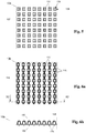
- FIGS 1a, 1b and 1c schematically show, in an axonometric projection, portions of three different bossed membranes (M1, M2, M3) of plastic sheet for underground and landfill applications, according to the prior art; respectively, as a non-exhaustive example, please consider said membrane Platon by the company Isola AS - Porsgrunn, said membrane Tefond by the company TeMa Technologies and Materials Srl, and said membrane Leakdrain by the English company ABG Limited.
- the membranes of Figures 1a and 1b are provided with frustoconical bosses arranged with a regular pitch, wherein in the first one (M1) the overall thickness (H1) is of about 7.5 mm with a pitch P1 of 26 mm for a distribution density of about 1600 bosses/m 2 , while in the second one (M2) the overall thickness (H2) is of about 20 mm with a pitch P2 of 20 mm for a density of about 2500 bosses/m 2 .
- the bosses are shaped as a truncated pyramid and the overall thickness (H3) is of about 5 mm with a pitch P3 of about 7.4 mm for a distribution density of about 19000 bosses/m 2 ;
- Figure 1d is a cross-section of the previous portion of membrane (M3), in correspondence of the bosses.
- the views are schematic; in order to facilitate understanding, said portions of membrane have the same size, conventionally being square with a unitary side (U) of 52 mm.
- Figure 2a shows, in an axonometric projection, a portion of bossed membrane of plastic sheet according to the present invention; the bosses are frustoconical with a head in the form of a spherical and deformable cap, for an overall thickness (H4) of less than 7 mm, for example 5 mm, and a pitch (P4) at most of 6.8 mm, that is to say, with about 64 bosses per said square portion of unitary side (U) of 52 mm, for a distribution density higher than 25000 bosses/m 2 .
- Figure 2b is an enlarged detail of the previous Figure 2a .
- Figure 3a is an orthogonal top view of a portion of the bossed membrane provided by the invention;
- Figure 3b refers to the section plane X1-X1 as in the previous view.
- Figure 3c is an enlarged detail of the single boss, as in the hatched circle in the previous view.
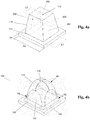
- Figure 4a is a schematic axonometric view, with sharp edges, of the geometries that generate the boss provided by the invention, where internally the overall dimensions of the punch shaped as a truncated pyramid that forms the inner surface are shown with a hatched line;
- Figure 4b shows the boss shaped as a finished product.
- Figure 5 is an orthogonal view from the bottom of the portion of bossed membrane as in said Figure 2 .
- Figures 6a and 6b refer to an embodiment variant of the invention, with non-slip projections that protrude from the lower surface;
- Figure 6a refers to the section plane X2-X2 as in the following view from the bottom, that is to say, Figure 6b .
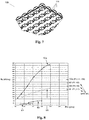
- Figure 7 shows an axonometric detail, seen from the bottom, of said embodiment variant with non-slip projections as in the previous Figures 6a and 6b .
- Figure 8 is a Cartesian two-dimensional diagram that represents experimental values of compressive strength (Rc), depending on the weight (Pm) of the membrane, relating to tests performed according to the ASTM D1621-16 standard on the bossed membrane according to the invention (10a, 10b), which are also compared with the corresponding tests performed on said conventional prior art membranes (M1, M2, M3).
- the present invention relates to a safety draining and waterproofing bossed membrane (10a, 10b) for landfills, mines or tunnels, which enables efficient drainage and waterproofing under heavy loads, with high compressive strength, and which at the same time limits the mechanical stresses on the interface layers, preventing cracking thereof.
- the proposed membrane includes hollow protrusions shaped as a truncated pyramid and particularly configured for protection purposes and for progressive yielding, as described hereinafter.
- Said protrusions which are conventionally called bosses (100), are small-sized, identical to each other, and are arranged in a regular pattern with a reduced pitch (P4) with respect to the conventional solutions in such a way as to obtain a very high distribution density, i.e. higher than 25000 bosses/m 2 ; the overall thickness (H4) of the finished membrane is between 3 mm and 7 mm, with a weight between 400 g/m 2 and 1500 g/m 2 .
- Said membrane is made of a plastic sheet (104) having a thickness (S1) between 0.45 mm and 1.6 mm, of HDPE, PP or a mixture thereof.
- a body shaped as a truncated pyramid (101) is provided on which a cap (110) rests whose bending radius is about half the size of the side of the lower base of the truncated pyramid itself, as described in detail hereinafter ( Figs. 3c , 4a, 4b ).
- the bossed membrane is laid in contact with layers of bentonite or GCL, or also HDPE sheets having a thickness of about 2 mm used as waterproofing elements.
- GCL bentonite
- HDPE sheets having a thickness of about 2 mm used as waterproofing elements.
- the cap shape of the boss prevents said damage and also allows the fluids to move better.
- the cap provides the capability to absorb a compressive stress more effectively with respect to a pointed or flat-headed protrusion, like a shock-absorbing effect.
- the boss (100) has the head (102) in the form of a spherical cap (110), that is to say, externally rounded like a semi-spherical dome resting on a truncated pyramid in such a way as to be externally joined in correspondence of the rounded side edges, tangent to them, that is to say, in rounding continuity ( Figs. 2b, 4b ); basically, said head on the outside appears like a ribbed vaulted dome on a square plan, being laterally cut by the flat walls of a truncated pyramid.
- the bottom (109) of the cavity (107) is flat and is such as to create on the sides a reduction in the thickness (S1) of the plastic material like a neck (111) that results in the progressive deformation of the boss (100) under load.
- the particular combination of shape, size, material, thickness and distribution of the bosses (100) allows the proposed membrane (10a, 10b) to uniformly redistribute the loads among the bosses, with the following combined effects: anti-collapse, that is to say, anti-crushing of the bosses, anti-obstruction for the purpose of drainage continuity and anti-crack of the interface layers.
- the membrane according to the invention (10a, 10b) ( Figs. 2-7 ) particularly provides a higher compressive strength than the conventionally used membranes, as in the most used prior art examples ( Figs. 1a, 1b, 1c, 1d ); such an advantage allows, for example, to ensure greater protection and safety and also allows to considerably reduce the weight and the cost of the membrane, facilitating its transport and laying.
- Experimental tests ( Fig.
- the third sample (M3) ( Figs. 1c, 1d ) has bosses shaped as a truncated pyramid having an overall thickness (H3) of about 5 mm and a pitch (P3) of about 7.4 mm, for a density of about 19000 bosses/m 2 .
- the sample of the draining and protective membrane according to the invention (10a, 10b) has said bosses (100) shaped as a truncated pyramid with a rectangular base and rounded edges, with the head (110) externally shaped as a deformable cap (102), according to the described modes and aims, having an overall thickness (H4) of about 5 mm and a pitch (P4) of about 6.5 mm, for a density higher than the conventional solutions, and namely of about 25600 bosses/m 2 .
- said spherical cap distributes the load in a more uniform way with respect to the conventional flat-headed protrusions, thus increasing compressive strength thanks to the initial squeezing of the spherical surface, followed by that of the base shaped as a truncated pyramid, obtaining an effective shock-absorbing and protective effect.
- said boss (100) has the inner surface of the cavity (106, 107) entirely shaped as a regular truncated pyramid since it is obtained by forming said sheet (104, S1) around a punch (200) shaped as a truncated pyramid with a rectangular base, having the greater base (201) that corresponds to the opening (108) of the cavity (107) and the smaller base (202) that forms the flat bottom (109) of said cavity, while on the opposite face of the head (102, 105) the outer surface is a spherical cap (110) in such a way as to form on the inside (102, 106, 107) a progressive reduction in the thickness of the material like a neck (111) that makes it yielding in a uniform and progressive way.
- the thickness of the head (102) is at most equal to the thickness of the sheet (S1) in the centre near the upper support (112) and, laterally, where it is joined to the body (101, 115).
- the outer edges (114) At the base (103) of said boss (100) the outer edges (114) have a radius (R2) that is greater with respect to the natural shrinkage of the material (R3) in such a way as to stiffen the base (103) with respect to the body (101).
- said truncated pyramid corresponding to the inner surface of the cavity (200, 106, 107), has the larger base (201, 108) with the sides (L1) having a length of 3.4 mm with a tolerance of ⁇ 1 mm, while the smaller base (202, 109) has the sides (L2) having a length of 2 mm with a tolerance of ⁇ 0,5 mm, wherein the distance (H5) between said bases (201, 202) is of 4.5 mm with a tolerance of ⁇ 1.5 mm, with the edges (203) rounded according to the natural shrinkage of the material.
- Said spherical cap (110) has a radius (R1) equal to half said larger side (L1), with a tolerance of ⁇ 10%, and is joined on the side edges (115) of said body (101) shaped as a truncated pyramid, they (115) being preferably rounded according to the natural shrinkage of the material (R3), that is to say, of about 0.5 mm considering a medium thickness of the sheet.
- a cap (110, R1) that correctly surmounts said punch (200) shaped as a truncated pyramid, joining in a tangent way said rounded side edges (R3), that is to say, in superficial continuity outside said body (101), like a ribbed vault on a square-based drum.
- the outer edges (114) have a radius (R2) equal to about half said side (L1) of the larger base (201) of the punch shaped as a truncated pyramid, with a tolerance of ⁇ 0,5 mm, or preferably of about 1.7 mm.
- the above-described membrane (Figs. 2-4 ) is not completely smooth ( Fig. 5 ) in the back surface (106) but has, in correspondence of the supporting plane, that is to say, excluding said cavities (107) ( Fig. 6a ), multiple non-slip projections (116), which are preferably shaped as small protrusions with a toroidal portion ( Figs. 6b, 7 ) like protruding fins aligned along a centreline axis of said boss (100), wherein said projections are parallel to each other and discontinuous since they are interrupted by said openings (107, 108).
- Said non-slip projections (116) have dimensions in thickness and width, considered in cross-section ( Fig. 6b ) in the point of maximum protrusion, that is to say, in the centre of each projection (116), having a value between once and twice the thickness (S1) of said sheet (104), in such a way as to improve the adhesion of the membrane to the underlying layers, facilitating laying on walls or very steep slopes, as for example occurs on the side flanks in landfills. It was observed in practice that such a solution, during laying, allows to increase the friction of said bossed membrane on the interface layers, such as the bentonite layers or the HDPE sheets, preventing sliding and ensuring continuous protection.
- the process for industrially obtaining the above-described bossed membrane (10a, 10b, 100) includes the following operating steps: first of all, extruding said plastic material in such a way as to form a thin sheet (104), according to the thickness (S1) corresponding to the weight (Pm) of the finished membrane, and namely the planned grammage; then forming said sheet around a forming roller provided with protrusions acting as forming punches (200), which are shaped as a regular truncated pyramid and are arranged in a pattern with a constant pitch (P4), with a height (H4) between said bases (201, 202) that is such as to obtain the desired overall thickness (H5), according to the desired weight.
- a thickening is provided on said punch shaped as a truncated pyramid (200, H5), which is centrally equal to 0.73 mm with a tolerance of +/- 0.25 mm.
- the variation in thickness of the head (102, 109, 110) for the purpose of said deformation (113) and of said progressive yielding, as provided by the invention can be industrially obtained by employing vacuum rotary rollers and stretching the extruded material around the smaller base (202, 109) of said punch (200) during the rotation, deforming it and thinning it in such a way as to obtain a rounded outer surface in the form of a spherical cap while the upper end, of support (112) for the external interface, has the greater thickness (S1), that is to say, it is substantially equal to the thickness of the sheet (104).
- the thickness of the material is substantially constant since they are substantially obtained by flat forming of a hot sheet, for example on a plate with protrusions on which a die for the counter-forming of the sheet, like moulding, is lowered.
- the safety draining and waterproofing membrane (10a, 10b) according to the invention achieves the planned aims, considerably improving the insulation and the protection of underground works such as, in particular, landfills, mines or tunnels.
- the proposed solution is particularly suitable for forming a draining and protective layer on the bottom and on the flanks of landfills for the collection of leachate and/or of groundwater, as well as intended to form a draining layer between the topsoil and the membranes or covering layers of said landfills.
Landscapes
- Engineering & Computer Science (AREA)
- Civil Engineering (AREA)
- Structural Engineering (AREA)
- Architecture (AREA)
- Life Sciences & Earth Sciences (AREA)
- Hydrology & Water Resources (AREA)
- Environmental & Geological Engineering (AREA)
- General Life Sciences & Earth Sciences (AREA)
- Mining & Mineral Resources (AREA)
- Paleontology (AREA)
- General Engineering & Computer Science (AREA)
- Lining And Supports For Tunnels (AREA)
- Processing Of Solid Wastes (AREA)
Claims (6)
- Genoppte Sicherheitsentleerungs- und Abdichtungsmembran (10a, 10b) für Deponien, Minen oder Tunnel mit einem Gewicht zwischen 400 g/m2 und 1500 g/m2 einer Kunststofffolie (104) mit einer Dicke (S1) zwischen 0,45 mm und 1,6 mm HDPE, PP oder Gemischen der beiden Materialien, versehen mit kleinen Noppen (100), die als Pyramidenstumpf geformt sind, miteinander identisch sind und in einer regelmäßigen Matrix mit hoher Verteilungsdichte angeordnet sind; wobei die genannte genoppte Membran (10a, 10b) eine Gesamtdicke (H4) zwischen 3 mm und 7 mm aufweist; wobei die genannte genoppte Membran (10a, 10b) dadurch gekennzeichnet ist, dass sie eine Verteilungsdichte der genannten Noppen (100) aufweist, die höher als 25000 Noppen/m2 ist, mit einem Abstand (P4) zwischen 6 mm und 6,8 mm, wobei der einzelne Noppe (100) eine Form des kombinierten Typs aufweist, die aus einem Körper (101) besteht, der als Pyramidenstumpf geformt ist, der als starre tragende Struktur wirkt, und aus einem Kopf (102) mit einer verformbaren Kugelkappe (110), die (101, 102, 110) miteinander verriegelt und verbunden sind, so dass sie bei konzentrierter Belastung zunehmend nachgeben; wobei der genannte Noppe (100) zuerst in Übereinstimmung mit dem genannten Kopf (102) nachgibt und erst am Ende an der Basis (103) des genannten Körpers (101) zusammengedrückt wird, wie ein Absorber - Stoßdämpfer, so dass die Belastungen gleichmäßig auf die Noppen (100) verteilt werden und ein Zusammenfallen verhindert wird, auch mit einer Anti-Verstopfungs-Wirkung zum Zwecke der Entwässerung und einer Anti-Riss-Wirkung in Richtung der Grenzflächenschichten; der genannte Noppe (100), wobei die Innenfläche des Hohlraums (106, 107) vollständig als regelmäßiger Pyramidenstumpf geformt ist, wird erhalten, indem die genannte Folie (104, S1) um einen Stempel herum geformt wird, der als Pyramidenstumpf (200) mit einer rechteckigen Basis geformt ist, wobei die größere Basis (201) der Öffnung (108) des Hohlraums (107) entspricht und die kleinere Basis (202) den flachen Boden (106, 109) des genannten Hohlraums bildet, während auf der gegenüberliegenden Fläche des Kopfes (102, 105) die Außenfläche eine Kugelkappe (110) ist, so dass auf der Innenfläche (102, 106, 107) eine fortschreitende Verringerung der Dicke des Materials (111) entsteht, wie bei einer Einschnürung, die es auf gleichmäßige und progressive Weise nachgiebig macht; wobei die Dicke des Kopfes (102) höchstens gleich der Dicke der Folie (S1) in Übereinstimmung mit der oberen Stütze (112) ist und seitlich, wo es mit dem Körper (115) verbunden ist, und wobei an der Basis (103) der genannten Noppen (100) die Außenkanten (114) einen Radius (R2) aufweisen, der in Bezug auf die natürliche Schrumpfung des Materials (R3) größer ist, so dass die Basis (103) in Bezug auf den Körper (101) versteift wird.
- Genoppte Membran (10a, 10b) nach Anspruch 1, dadurch gekennzeichnet, dass der genannte Pyramidenstumpf, der der Innenfläche des Hohlraums (200, 106, 107) entspricht, die größere Basis (201, 108) hat, mit den Seiten (L1) mit einer Länge von 3,4 mm mit einer Toleranz von ± 1 mm, während es die kleinere Basis (202, 109) hat, wobei die Seiten (L2) eine Länge von 2 mm mit einer Toleranz von ± 0,5 mm haben, wobei der Abstand (H5) zwischen den genannten Basen (201, 202) 4,5 mm mit einer Toleranz von ± 1,5 mm beträgt, mit abgerundeten Kanten (203) entsprechend der natürlichen Schrumpfung des Materials; und wobei die genannte Kugelkappe (110) einen Radius (R1) hat, der gleich der Hälfte der genannten größeren Seite (L1) ist, mit einer Toleranz von ± 10%, und an den Seitenkanten (115) des genannten Körpers (101) verbunden ist, der als Pyramidenstumpf geformt ist, die entsprechend der natürlichen Schrumpfung des Materials gerundet sind (R3); und wobei an der Basis (103) der genannten Noppe (100), die genannten Außenkanten (114) den Radius (R2) haben, der gleich der Hälfte der Seite (L1) der größeren Basis (201) mit einer Toleranz von ± 0,5 mm ist; und wobei der genannte Abstand (P4) zwischen den genannten Noppen (100) 6,5 mm beträgt, mit einer Verteilungsdichte von 25600 Noppen/m2 und derart, dass 64 Noppen in einem quadratischen Abschnitt der Membran mit einer Seite von 52 mm erhalten werden; wobei die genannten Werte mit einer Toleranz von ± 5% berücksichtigt werden.
- Genoppte Membran (10a, 10b) nach den Ansprüchen 1 und 2, dadurch gekennzeichnet, dass sie eine Druckfestigkeit (Rc) gemäß der Norm ASTM D1621-16 aufweist, die zwischen 800 kN/m2 und 4800 kN/m2 liegt, abhängig von der Dicke (S1) der Kunststofffolie (Fig. 8), wobei der erste Wert mit einer Dicke (S1) von 0,45 mm und der zweite Wert mit einer Dicke (S1) von 1,2 mm erhalten wird, wobei die Zwischenwerte mit einer Toleranz von ± 15% direkt proportional zur Dickenänderung sind.
- Genoppte Membran (10b) nach Anspruch 1 oder 2 oder 3, dadurch gekennzeichnet, dass sie die untere Fläche (106) in einem Lagerzustand aufweist, die mit mehreren rutschfesten Erhebungen (116) versehen ist, die entlang einer Mittellinienachse der genannten Noppen (100) ausgerichtet sind, die parallel zueinander und diskontinuierlich sind, da sie durch die genannten Öffnungen (107, 108) unterbrochen werden.
- Genoppte Membran (10b) gemäß dem vorherigen Anspruch, dadurch gekennzeichnet, dass die genannten rutschfesten Erhebungen (116) als kleine Vorsprünge mit einem Ringabschnitt (Fig. 6b, 7) oder als abgerundeten und hervorstehenden Rippen sowohl quer als auch in Längsrichtung geformt sind; wobei die genannten rutschfesten Erhebungen (116) eine variable Dicke und Breite aufweisen, die im Querschnitt am Punkt des maximalen Vorsprungs in der Mitte jeder Erhebung (116) zwischen ein- und zweimal der Dicke (S1) der genannten Folie (104) liegen.
- Genoppte Membran (10a, 10b) nach mindestens einem der vorherigen Ansprüche, dadurch gekennzeichnet, dass sie industriell durch ein Verfahren erhalten wird, das die folgenden Betriebsschritte umfasst: ein erstes Extrudieren des genannten Kunststoffmaterials, so dass eine dünne Folie (104) entsprechend der Dicke (S1) gebildet wird, die dem Gewicht (Pm) der fertigen Membran entspricht, und dann Formen der genannten Folie um eine Formwalze, die mit Vorsprüngen versehen ist, die als Formstempel (200) wirken, die als regelmäßige Pyramidenstümpfe geformt sind und in einer Matrix mit einer konstanten Teilung (P4) angeordnet sind, wobei zwischen den genannten Basen (201, 202) eine Höhe (H4) besteht, die so ist, dass die gewünschte Gesamtdicke (H5) entsprechend dem gewünschten Gewicht erhalten wird; und wobei die Änderung der Dicke des Kopfes (102, 109, 110) zum Zweck der Verformung (113) und der fortschreitenden Nachgiebigkeit mit einer Vakuumrotationswalze und durch Strecken des Materials erhalten wird, das während der Drehung um die kleinere Basis (202, 109) des genannten Stempels (200) extrudiert wird, Verformen und Ausdünnen mit Einschnüren (111), so dass eine als Kugelkappe (110) abgerundete Außenfläche erhalten wird während das obere Ende die größere Dicke (S1, 112) aufweist oder im Wesentlichen gleich der Dicke der Folie (104) ist.
Priority Applications (1)
| Application Number | Priority Date | Filing Date | Title |
|---|---|---|---|
| PL18020485T PL3467208T3 (pl) | 2017-10-09 | 2018-10-04 | Zabezpieczająca membrana z wypukłościami dla wysypisk |
Applications Claiming Priority (1)
| Application Number | Priority Date | Filing Date | Title |
|---|---|---|---|
| IT102017000112845A IT201700112845A1 (it) | 2017-10-09 | 2017-10-09 | "membrana bugnata di sicurezza per discariche" |
Publications (2)
| Publication Number | Publication Date |
|---|---|
| EP3467208A1 EP3467208A1 (de) | 2019-04-10 |
| EP3467208B1 true EP3467208B1 (de) | 2020-08-19 |
Family
ID=61148397
Family Applications (1)
| Application Number | Title | Priority Date | Filing Date |
|---|---|---|---|
| EP18020485.1A Active EP3467208B1 (de) | 2017-10-09 | 2018-10-04 | Genoppte sicherheitfolie für deponien |
Country Status (6)
| Country | Link |
|---|---|
| EP (1) | EP3467208B1 (de) |
| ES (1) | ES2829401T3 (de) |
| HU (1) | HUE051768T2 (de) |
| IT (1) | IT201700112845A1 (de) |
| PL (1) | PL3467208T3 (de) |
| ZA (1) | ZA201806499B (de) |
Families Citing this family (2)
| Publication number | Priority date | Publication date | Assignee | Title |
|---|---|---|---|---|
| EP3889359A1 (de) * | 2020-03-31 | 2021-10-06 | Recyplast Holding AG | Verfahren zum herstellen einer folie aus polyethylen; folie aus polyethylen |
| EP4200497A1 (de) * | 2020-08-19 | 2023-06-28 | IWIS Insulation Waterproofing Industrial Systems S.R.L. | Mehrschichtplatte für den baubereich und verfahren zum verlegen derselben |
Family Cites Families (7)
| Publication number | Priority date | Publication date | Assignee | Title |
|---|---|---|---|---|
| GB8611941D0 (en) | 1986-05-16 | 1986-06-25 | Schlegel Uk Holdings | Protection membrane |
| DK9500492U3 (da) * | 1995-12-27 | 1996-02-23 | Oldroyd Systemer As | Membran |
| US6691472B2 (en) * | 2002-02-15 | 2004-02-17 | Theodore G. Hubert | Foundation wall protector |
| GB0422333D0 (en) * | 2004-10-08 | 2004-11-10 | Abg Ltd | Drained barrier |
| DE202006001699U1 (de) * | 2006-02-01 | 2006-06-01 | Gutta-Werke Gmbh | Abdeckelement zum Schutz von Bauwerksteilen und Walze zu dessen Herstellung |
| DE102009053633A1 (de) * | 2009-11-17 | 2011-05-19 | Droog, Stephan M. | Noppenelement |
| WO2013150459A1 (en) * | 2012-04-03 | 2013-10-10 | Biosafe - Indústria De Reciclagens, S.A. | High performance shock pad, method of manufacture thereof and its use |
-
2017
- 2017-10-09 IT IT102017000112845A patent/IT201700112845A1/it unknown
-
2018
- 2018-10-01 ZA ZA2018/06499A patent/ZA201806499B/en unknown
- 2018-10-04 EP EP18020485.1A patent/EP3467208B1/de active Active
- 2018-10-04 HU HUE18020485A patent/HUE051768T2/hu unknown
- 2018-10-04 PL PL18020485T patent/PL3467208T3/pl unknown
- 2018-10-04 ES ES18020485T patent/ES2829401T3/es active Active
Non-Patent Citations (1)
| Title |
|---|
| None * |
Also Published As
| Publication number | Publication date |
|---|---|
| IT201700112845A1 (it) | 2019-04-09 |
| ES2829401T3 (es) | 2021-05-31 |
| EP3467208A1 (de) | 2019-04-10 |
| HUE051768T2 (hu) | 2021-03-29 |
| PL3467208T4 (pl) | 2021-06-14 |
| ZA201806499B (en) | 2019-06-26 |
| PL3467208T3 (pl) | 2021-06-14 |
Similar Documents
| Publication | Publication Date | Title |
|---|---|---|
| US8440289B2 (en) | Composite for geotechnics, building and the like, with impermeable layer | |
| US5258217A (en) | Landfill liner | |
| EP3467208B1 (de) | Genoppte sicherheitfolie für deponien | |
| EP0890002B1 (de) | Geo-verbundmembran | |
| CN205475357U (zh) | 一种用于渗流量大的生活垃圾填埋场的双层hdpe膜复合衬里防渗结构 | |
| EP1807573B1 (de) | Drainagesperre | |
| WO2004074589A2 (en) | High friction scrims, geonets, laminates and methods for using and making them | |
| EP3283286B1 (de) | SELBSTDICHTENDE, SELBSTREPARIERENDE
 WASSERSPERRENDE MEMBRAN ZUR ISOLIERUNG VON GEBÄUDESTRUKTUREN, DIE HYDROSTATISCHEM DRUCK AUSGESETZT SIND | |
| US3343370A (en) | Earth embankment with internal water barrier | |
| CN214401902U (zh) | 一种用于刚性危废填埋场可回取单元的防渗机构 | |
| EP2616593B1 (de) | Verbundmaterial | |
| KR102810806B1 (ko) | 폐기물 매립장의 침출수 차단용 차수시트 | |
| CN206844170U (zh) | 用于垃圾填埋场的竖向扩容结构 | |
| US20070183852A1 (en) | High-friction geo-textiles for increasing the stability of landfill drainage layers and other high-friction angle installations, and related methods | |
| RU210625U1 (ru) | Дренажно-армирующий геокомпозит рулонного типа | |
| US11141952B2 (en) | Sludge covers, sludge management systems, and related methods | |
| KR20190025132A (ko) | 방수층 보호판 | |
| CN121228742A (zh) | 一种填埋场防渗膜与穿膜管连接结构及其施工方法 | |
| JP7490491B2 (ja) | 遮水シートの水中接合構造 | |
| RU2707214C2 (ru) | Защитно-дренажная мембрана с высокопрочными шипами, обеспечивающая эффект избежания повреждения | |
| GB2322098A (en) | Apparatus for gas and water drainage | |
| WO1997036059A1 (en) | Geotextile | |
| KR20240161361A (ko) | 폐기물 매립장 화재시 고온으로 부터 차수시트를 보호하는 폐기물 매립장의 침출수 차단용 차수시트 | |
| KR100328358B1 (ko) | 폐기물매립장의 경사면보호층 성형재 및 그 설치방법 | |
| EP2616592B1 (de) | Verbundmaterial, komponente für ein verbundmaterial und herstellungsverfahren |
Legal Events
| Date | Code | Title | Description |
|---|---|---|---|
| PUAI | Public reference made under article 153(3) epc to a published international application that has entered the european phase |
Free format text: ORIGINAL CODE: 0009012 |
|
| STAA | Information on the status of an ep patent application or granted ep patent |
Free format text: STATUS: THE APPLICATION HAS BEEN PUBLISHED |
|
| AK | Designated contracting states |
Kind code of ref document: A1 Designated state(s): AL AT BE BG CH CY CZ DE DK EE ES FI FR GB GR HR HU IE IS IT LI LT LU LV MC MK MT NL NO PL PT RO RS SE SI SK SM TR |
|
| AX | Request for extension of the european patent |
Extension state: BA ME |
|
| STAA | Information on the status of an ep patent application or granted ep patent |
Free format text: STATUS: REQUEST FOR EXAMINATION WAS MADE |
|
| 17P | Request for examination filed |
Effective date: 20190918 |
|
| GRAP | Despatch of communication of intention to grant a patent |
Free format text: ORIGINAL CODE: EPIDOSNIGR1 |
|
| STAA | Information on the status of an ep patent application or granted ep patent |
Free format text: STATUS: GRANT OF PATENT IS INTENDED |
|
| RIC1 | Information provided on ipc code assigned before grant |
Ipc: E01C 3/06 20060101ALI20200221BHEP Ipc: E01C 3/00 20060101ALI20200221BHEP Ipc: E02D 31/02 20060101AFI20200221BHEP Ipc: E01C 13/02 20060101ALI20200221BHEP |
|
| INTG | Intention to grant announced |
Effective date: 20200320 |
|
| GRAS | Grant fee paid |
Free format text: ORIGINAL CODE: EPIDOSNIGR3 |
|
| GRAA | (expected) grant |
Free format text: ORIGINAL CODE: 0009210 |
|
| STAA | Information on the status of an ep patent application or granted ep patent |
Free format text: STATUS: THE PATENT HAS BEEN GRANTED |
|
| AK | Designated contracting states |
Kind code of ref document: B1 Designated state(s): AL AT BE BG CH CY CZ DE DK EE ES FI FR GB GR HR HU IE IS IT LI LT LU LV MC MK MT NL NO PL PT RO RS SE SI SK SM TR |
|
| REG | Reference to a national code |
Ref country code: CH Ref legal event code: EP |
|
| REG | Reference to a national code |
Ref country code: DE Ref legal event code: R096 Ref document number: 602018006924 Country of ref document: DE |
|
| REG | Reference to a national code |
Ref country code: AT Ref legal event code: REF Ref document number: 1304073 Country of ref document: AT Kind code of ref document: T Effective date: 20200915 |
|
| REG | Reference to a national code |
Ref country code: IE Ref legal event code: FG4D |
|
| REG | Reference to a national code |
Ref country code: FI Ref legal event code: FGE |
|
| REG | Reference to a national code |
Ref country code: RO Ref legal event code: EPE |
|
| REG | Reference to a national code |
Ref country code: SE Ref legal event code: TRGR |
|
| REG | Reference to a national code |
Ref country code: LT Ref legal event code: MG4D |
|
| REG | Reference to a national code |
Ref country code: GR Ref legal event code: EP Ref document number: 20200403099 Country of ref document: GR Effective date: 20201215 |
|
| REG | Reference to a national code |
Ref country code: NO Ref legal event code: T2 Effective date: 20200819 |
|
| REG | Reference to a national code |
Ref country code: NL Ref legal event code: MP Effective date: 20200819 |
|
| PG25 | Lapsed in a contracting state [announced via postgrant information from national office to epo] |
Ref country code: PT Free format text: LAPSE BECAUSE OF FAILURE TO SUBMIT A TRANSLATION OF THE DESCRIPTION OR TO PAY THE FEE WITHIN THE PRESCRIBED TIME-LIMIT Effective date: 20201221 Ref country code: LT Free format text: LAPSE BECAUSE OF FAILURE TO SUBMIT A TRANSLATION OF THE DESCRIPTION OR TO PAY THE FEE WITHIN THE PRESCRIBED TIME-LIMIT Effective date: 20200819 Ref country code: BG Free format text: LAPSE BECAUSE OF FAILURE TO SUBMIT A TRANSLATION OF THE DESCRIPTION OR TO PAY THE FEE WITHIN THE PRESCRIBED TIME-LIMIT Effective date: 20201119 Ref country code: HR Free format text: LAPSE BECAUSE OF FAILURE TO SUBMIT A TRANSLATION OF THE DESCRIPTION OR TO PAY THE FEE WITHIN THE PRESCRIBED TIME-LIMIT Effective date: 20200819 |
|
| PG25 | Lapsed in a contracting state [announced via postgrant information from national office to epo] |
Ref country code: NL Free format text: LAPSE BECAUSE OF FAILURE TO SUBMIT A TRANSLATION OF THE DESCRIPTION OR TO PAY THE FEE WITHIN THE PRESCRIBED TIME-LIMIT Effective date: 20200819 Ref country code: LV Free format text: LAPSE BECAUSE OF FAILURE TO SUBMIT A TRANSLATION OF THE DESCRIPTION OR TO PAY THE FEE WITHIN THE PRESCRIBED TIME-LIMIT Effective date: 20200819 Ref country code: RS Free format text: LAPSE BECAUSE OF FAILURE TO SUBMIT A TRANSLATION OF THE DESCRIPTION OR TO PAY THE FEE WITHIN THE PRESCRIBED TIME-LIMIT Effective date: 20200819 Ref country code: IS Free format text: LAPSE BECAUSE OF FAILURE TO SUBMIT A TRANSLATION OF THE DESCRIPTION OR TO PAY THE FEE WITHIN THE PRESCRIBED TIME-LIMIT Effective date: 20201219 |
|
| REG | Reference to a national code |
Ref country code: HU Ref legal event code: AG4A Ref document number: E051768 Country of ref document: HU |
|
| PG25 | Lapsed in a contracting state [announced via postgrant information from national office to epo] |
Ref country code: SM Free format text: LAPSE BECAUSE OF FAILURE TO SUBMIT A TRANSLATION OF THE DESCRIPTION OR TO PAY THE FEE WITHIN THE PRESCRIBED TIME-LIMIT Effective date: 20200819 Ref country code: DK Free format text: LAPSE BECAUSE OF FAILURE TO SUBMIT A TRANSLATION OF THE DESCRIPTION OR TO PAY THE FEE WITHIN THE PRESCRIBED TIME-LIMIT Effective date: 20200819 Ref country code: CZ Free format text: LAPSE BECAUSE OF FAILURE TO SUBMIT A TRANSLATION OF THE DESCRIPTION OR TO PAY THE FEE WITHIN THE PRESCRIBED TIME-LIMIT Effective date: 20200819 Ref country code: EE Free format text: LAPSE BECAUSE OF FAILURE TO SUBMIT A TRANSLATION OF THE DESCRIPTION OR TO PAY THE FEE WITHIN THE PRESCRIBED TIME-LIMIT Effective date: 20200819 |
|
| REG | Reference to a national code |
Ref country code: DE Ref legal event code: R097 Ref document number: 602018006924 Country of ref document: DE |
|
| PG25 | Lapsed in a contracting state [announced via postgrant information from national office to epo] |
Ref country code: AL Free format text: LAPSE BECAUSE OF FAILURE TO SUBMIT A TRANSLATION OF THE DESCRIPTION OR TO PAY THE FEE WITHIN THE PRESCRIBED TIME-LIMIT Effective date: 20200819 |
|
| REG | Reference to a national code |
Ref country code: ES Ref legal event code: FG2A Ref document number: 2829401 Country of ref document: ES Kind code of ref document: T3 Effective date: 20210531 |
|
| PLBE | No opposition filed within time limit |
Free format text: ORIGINAL CODE: 0009261 |
|
| STAA | Information on the status of an ep patent application or granted ep patent |
Free format text: STATUS: NO OPPOSITION FILED WITHIN TIME LIMIT |
|
| PG25 | Lapsed in a contracting state [announced via postgrant information from national office to epo] |
Ref country code: LU Free format text: LAPSE BECAUSE OF NON-PAYMENT OF DUE FEES Effective date: 20201004 Ref country code: SK Free format text: LAPSE BECAUSE OF FAILURE TO SUBMIT A TRANSLATION OF THE DESCRIPTION OR TO PAY THE FEE WITHIN THE PRESCRIBED TIME-LIMIT Effective date: 20200819 Ref country code: MC Free format text: LAPSE BECAUSE OF FAILURE TO SUBMIT A TRANSLATION OF THE DESCRIPTION OR TO PAY THE FEE WITHIN THE PRESCRIBED TIME-LIMIT Effective date: 20200819 |
|
| REG | Reference to a national code |
Ref country code: BE Ref legal event code: MM Effective date: 20201031 |
|
| 26N | No opposition filed |
Effective date: 20210520 |
|
| PG25 | Lapsed in a contracting state [announced via postgrant information from national office to epo] |
Ref country code: IT Free format text: LAPSE BECAUSE OF FAILURE TO SUBMIT A TRANSLATION OF THE DESCRIPTION OR TO PAY THE FEE WITHIN THE PRESCRIBED TIME-LIMIT Effective date: 20200819 |
|
| PG25 | Lapsed in a contracting state [announced via postgrant information from national office to epo] |
Ref country code: BE Free format text: LAPSE BECAUSE OF NON-PAYMENT OF DUE FEES Effective date: 20201031 Ref country code: SI Free format text: LAPSE BECAUSE OF FAILURE TO SUBMIT A TRANSLATION OF THE DESCRIPTION OR TO PAY THE FEE WITHIN THE PRESCRIBED TIME-LIMIT Effective date: 20200819 |
|
| PG25 | Lapsed in a contracting state [announced via postgrant information from national office to epo] |
Ref country code: IE Free format text: LAPSE BECAUSE OF NON-PAYMENT OF DUE FEES Effective date: 20201004 |
|
| REG | Reference to a national code |
Ref country code: CH Ref legal event code: PL |
|
| PG25 | Lapsed in a contracting state [announced via postgrant information from national office to epo] |
Ref country code: MT Free format text: LAPSE BECAUSE OF FAILURE TO SUBMIT A TRANSLATION OF THE DESCRIPTION OR TO PAY THE FEE WITHIN THE PRESCRIBED TIME-LIMIT Effective date: 20200819 Ref country code: CY Free format text: LAPSE BECAUSE OF FAILURE TO SUBMIT A TRANSLATION OF THE DESCRIPTION OR TO PAY THE FEE WITHIN THE PRESCRIBED TIME-LIMIT Effective date: 20200819 |
|
| PG25 | Lapsed in a contracting state [announced via postgrant information from national office to epo] |
Ref country code: MK Free format text: LAPSE BECAUSE OF FAILURE TO SUBMIT A TRANSLATION OF THE DESCRIPTION OR TO PAY THE FEE WITHIN THE PRESCRIBED TIME-LIMIT Effective date: 20200819 |
|
| PG25 | Lapsed in a contracting state [announced via postgrant information from national office to epo] |
Ref country code: LI Free format text: LAPSE BECAUSE OF NON-PAYMENT OF DUE FEES Effective date: 20211031 Ref country code: CH Free format text: LAPSE BECAUSE OF NON-PAYMENT OF DUE FEES Effective date: 20211031 |
|
| P01 | Opt-out of the competence of the unified patent court (upc) registered |
Free format text: CASE NUMBER: APP_42434/2024 Effective date: 20240718 |
|
| REG | Reference to a national code |
Ref country code: AT Ref legal event code: UEP Ref document number: 1304073 Country of ref document: AT Kind code of ref document: T Effective date: 20200819 |
|
| PGFP | Annual fee paid to national office [announced via postgrant information from national office to epo] |
Ref country code: RO Payment date: 20250930 Year of fee payment: 8 |
|
| PGFP | Annual fee paid to national office [announced via postgrant information from national office to epo] |
Ref country code: HU Payment date: 20251007 Year of fee payment: 8 |
|
| PGFP | Annual fee paid to national office [announced via postgrant information from national office to epo] |
Ref country code: DE Payment date: 20251001 Year of fee payment: 8 |
|
| PGFP | Annual fee paid to national office [announced via postgrant information from national office to epo] |
Ref country code: GB Payment date: 20251007 Year of fee payment: 8 |
|
| PGFP | Annual fee paid to national office [announced via postgrant information from national office to epo] |
Ref country code: NO Payment date: 20250930 Year of fee payment: 8 |
|
| PGFP | Annual fee paid to national office [announced via postgrant information from national office to epo] |
Ref country code: AT Payment date: 20251029 Year of fee payment: 8 |
|
| PGFP | Annual fee paid to national office [announced via postgrant information from national office to epo] |
Ref country code: FI Payment date: 20251021 Year of fee payment: 8 |
|
| PGFP | Annual fee paid to national office [announced via postgrant information from national office to epo] |
Ref country code: FR Payment date: 20251029 Year of fee payment: 8 |
|
| PGFP | Annual fee paid to national office [announced via postgrant information from national office to epo] |
Ref country code: GR Payment date: 20251003 Year of fee payment: 8 Ref country code: TR Payment date: 20251003 Year of fee payment: 8 |
|
| PGFP | Annual fee paid to national office [announced via postgrant information from national office to epo] |
Ref country code: SE Payment date: 20251003 Year of fee payment: 8 |
|
| PGFP | Annual fee paid to national office [announced via postgrant information from national office to epo] |
Ref country code: PL Payment date: 20251001 Year of fee payment: 8 |
|
| PGFP | Annual fee paid to national office [announced via postgrant information from national office to epo] |
Ref country code: ES Payment date: 20251106 Year of fee payment: 8 |