EP3465861B1 - Procede d'alimentation electrique d'un equipement par une station autonome hybride - Google Patents
Procede d'alimentation electrique d'un equipement par une station autonome hybride Download PDFInfo
- Publication number
- EP3465861B1 EP3465861B1 EP17732511.5A EP17732511A EP3465861B1 EP 3465861 B1 EP3465861 B1 EP 3465861B1 EP 17732511 A EP17732511 A EP 17732511A EP 3465861 B1 EP3465861 B1 EP 3465861B1
- Authority
- EP
- European Patent Office
- Prior art keywords
- power balance
- power
- threshold
- fuel cell
- electrochemical unit
- Prior art date
- Legal status (The legal status is an assumption and is not a legal conclusion. Google has not performed a legal analysis and makes no representation as to the accuracy of the status listed.)
- Active
Links
Images

Classifications
-
- H—ELECTRICITY
- H02—GENERATION; CONVERSION OR DISTRIBUTION OF ELECTRIC POWER
- H02J—CIRCUIT ARRANGEMENTS OR SYSTEMS FOR SUPPLYING OR DISTRIBUTING ELECTRIC POWER; SYSTEMS FOR STORING ELECTRIC ENERGY
- H02J3/00—Circuit arrangements for AC mains or AC distribution networks
- H02J3/28—Arrangements for balancing of the load in a network by storage of energy
-
- H—ELECTRICITY
- H01—ELECTRIC ELEMENTS
- H01M—PROCESSES OR MEANS, e.g. BATTERIES, FOR THE DIRECT CONVERSION OF CHEMICAL ENERGY INTO ELECTRICAL ENERGY
- H01M16/00—Structural combinations of different types of electrochemical generators
- H01M16/003—Structural combinations of different types of electrochemical generators of fuel cells with other electrochemical devices, e.g. capacitors, electrolysers
- H01M16/006—Structural combinations of different types of electrochemical generators of fuel cells with other electrochemical devices, e.g. capacitors, electrolysers of fuel cells with rechargeable batteries
-
- H—ELECTRICITY
- H01—ELECTRIC ELEMENTS
- H01M—PROCESSES OR MEANS, e.g. BATTERIES, FOR THE DIRECT CONVERSION OF CHEMICAL ENERGY INTO ELECTRICAL ENERGY
- H01M8/00—Fuel cells; Manufacture thereof
- H01M8/04—Auxiliary arrangements, e.g. for control of pressure or for circulation of fluids
- H01M8/04298—Processes for controlling fuel cells or fuel cell systems
- H01M8/04313—Processes for controlling fuel cells or fuel cell systems characterised by the detection or assessment of variables; characterised by the detection or assessment of failure or abnormal function
- H01M8/04537—Electric variables
- H01M8/04604—Power, energy, capacity or load
-
- H—ELECTRICITY
- H01—ELECTRIC ELEMENTS
- H01M—PROCESSES OR MEANS, e.g. BATTERIES, FOR THE DIRECT CONVERSION OF CHEMICAL ENERGY INTO ELECTRICAL ENERGY
- H01M8/00—Fuel cells; Manufacture thereof
- H01M8/04—Auxiliary arrangements, e.g. for control of pressure or for circulation of fluids
- H01M8/04298—Processes for controlling fuel cells or fuel cell systems
- H01M8/04694—Processes for controlling fuel cells or fuel cell systems characterised by variables to be controlled
- H01M8/04955—Shut-off or shut-down of fuel cells
-
- H—ELECTRICITY
- H02—GENERATION; CONVERSION OR DISTRIBUTION OF ELECTRIC POWER
- H02J—CIRCUIT ARRANGEMENTS OR SYSTEMS FOR SUPPLYING OR DISTRIBUTING ELECTRIC POWER; SYSTEMS FOR STORING ELECTRIC ENERGY
- H02J15/00—Systems for storing electric energy
- H02J15/007—Systems for storing electric energy involving storage in the form of mechanical energy, e.g. fly-wheels
-
- H—ELECTRICITY
- H02—GENERATION; CONVERSION OR DISTRIBUTION OF ELECTRIC POWER
- H02J—CIRCUIT ARRANGEMENTS OR SYSTEMS FOR SUPPLYING OR DISTRIBUTING ELECTRIC POWER; SYSTEMS FOR STORING ELECTRIC ENERGY
- H02J3/00—Circuit arrangements for AC mains or AC distribution networks
- H02J3/28—Arrangements for balancing of the load in a network by storage of energy
- H02J3/32—Arrangements for balancing of the load in a network by storage of energy using batteries with converting means
-
- H—ELECTRICITY
- H02—GENERATION; CONVERSION OR DISTRIBUTION OF ELECTRIC POWER
- H02J—CIRCUIT ARRANGEMENTS OR SYSTEMS FOR SUPPLYING OR DISTRIBUTING ELECTRIC POWER; SYSTEMS FOR STORING ELECTRIC ENERGY
- H02J3/00—Circuit arrangements for AC mains or AC distribution networks
- H02J3/38—Arrangements for parallely feeding a single network by two or more generators, converters or transformers
- H02J3/381—Dispersed generators
-
- H—ELECTRICITY
- H01—ELECTRIC ELEMENTS
- H01M—PROCESSES OR MEANS, e.g. BATTERIES, FOR THE DIRECT CONVERSION OF CHEMICAL ENERGY INTO ELECTRICAL ENERGY
- H01M8/00—Fuel cells; Manufacture thereof
- H01M8/04—Auxiliary arrangements, e.g. for control of pressure or for circulation of fluids
- H01M8/04298—Processes for controlling fuel cells or fuel cell systems
- H01M8/04313—Processes for controlling fuel cells or fuel cell systems characterised by the detection or assessment of variables; characterised by the detection or assessment of failure or abnormal function
- H01M8/04537—Electric variables
-
- H—ELECTRICITY
- H02—GENERATION; CONVERSION OR DISTRIBUTION OF ELECTRIC POWER
- H02J—CIRCUIT ARRANGEMENTS OR SYSTEMS FOR SUPPLYING OR DISTRIBUTING ELECTRIC POWER; SYSTEMS FOR STORING ELECTRIC ENERGY
- H02J1/00—Circuit arrangements for DC mains or DC distribution networks
- H02J1/10—Parallel operation of DC sources
-
- H—ELECTRICITY
- H02—GENERATION; CONVERSION OR DISTRIBUTION OF ELECTRIC POWER
- H02J—CIRCUIT ARRANGEMENTS OR SYSTEMS FOR SUPPLYING OR DISTRIBUTING ELECTRIC POWER; SYSTEMS FOR STORING ELECTRIC ENERGY
- H02J15/00—Systems for storing electric energy
- H02J15/008—Systems for storing electric energy using hydrogen as energy vector
-
- H—ELECTRICITY
- H02—GENERATION; CONVERSION OR DISTRIBUTION OF ELECTRIC POWER
- H02J—CIRCUIT ARRANGEMENTS OR SYSTEMS FOR SUPPLYING OR DISTRIBUTING ELECTRIC POWER; SYSTEMS FOR STORING ELECTRIC ENERGY
- H02J2300/00—Systems for supplying or distributing electric power characterised by decentralized, dispersed, or local generation
- H02J2300/20—The dispersed energy generation being of renewable origin
- H02J2300/22—The renewable source being solar energy
- H02J2300/24—The renewable source being solar energy of photovoltaic origin
-
- H—ELECTRICITY
- H02—GENERATION; CONVERSION OR DISTRIBUTION OF ELECTRIC POWER
- H02J—CIRCUIT ARRANGEMENTS OR SYSTEMS FOR SUPPLYING OR DISTRIBUTING ELECTRIC POWER; SYSTEMS FOR STORING ELECTRIC ENERGY
- H02J2300/00—Systems for supplying or distributing electric power characterised by decentralized, dispersed, or local generation
- H02J2300/20—The dispersed energy generation being of renewable origin
- H02J2300/28—The renewable source being wind energy
-
- H—ELECTRICITY
- H02—GENERATION; CONVERSION OR DISTRIBUTION OF ELECTRIC POWER
- H02J—CIRCUIT ARRANGEMENTS OR SYSTEMS FOR SUPPLYING OR DISTRIBUTING ELECTRIC POWER; SYSTEMS FOR STORING ELECTRIC ENERGY
- H02J2300/00—Systems for supplying or distributing electric power characterised by decentralized, dispersed, or local generation
- H02J2300/30—The power source being a fuel cell
-
- Y—GENERAL TAGGING OF NEW TECHNOLOGICAL DEVELOPMENTS; GENERAL TAGGING OF CROSS-SECTIONAL TECHNOLOGIES SPANNING OVER SEVERAL SECTIONS OF THE IPC; TECHNICAL SUBJECTS COVERED BY FORMER USPC CROSS-REFERENCE ART COLLECTIONS [XRACs] AND DIGESTS
- Y02—TECHNOLOGIES OR APPLICATIONS FOR MITIGATION OR ADAPTATION AGAINST CLIMATE CHANGE
- Y02E—REDUCTION OF GREENHOUSE GAS [GHG] EMISSIONS, RELATED TO ENERGY GENERATION, TRANSMISSION OR DISTRIBUTION
- Y02E10/00—Energy generation through renewable energy sources
- Y02E10/50—Photovoltaic [PV] energy
- Y02E10/56—Power conversion systems, e.g. maximum power point trackers
-
- Y—GENERAL TAGGING OF NEW TECHNOLOGICAL DEVELOPMENTS; GENERAL TAGGING OF CROSS-SECTIONAL TECHNOLOGIES SPANNING OVER SEVERAL SECTIONS OF THE IPC; TECHNICAL SUBJECTS COVERED BY FORMER USPC CROSS-REFERENCE ART COLLECTIONS [XRACs] AND DIGESTS
- Y02—TECHNOLOGIES OR APPLICATIONS FOR MITIGATION OR ADAPTATION AGAINST CLIMATE CHANGE
- Y02E—REDUCTION OF GREENHOUSE GAS [GHG] EMISSIONS, RELATED TO ENERGY GENERATION, TRANSMISSION OR DISTRIBUTION
- Y02E60/00—Enabling technologies; Technologies with a potential or indirect contribution to GHG emissions mitigation
- Y02E60/10—Energy storage using batteries
-
- Y—GENERAL TAGGING OF NEW TECHNOLOGICAL DEVELOPMENTS; GENERAL TAGGING OF CROSS-SECTIONAL TECHNOLOGIES SPANNING OVER SEVERAL SECTIONS OF THE IPC; TECHNICAL SUBJECTS COVERED BY FORMER USPC CROSS-REFERENCE ART COLLECTIONS [XRACs] AND DIGESTS
- Y02—TECHNOLOGIES OR APPLICATIONS FOR MITIGATION OR ADAPTATION AGAINST CLIMATE CHANGE
- Y02E—REDUCTION OF GREENHOUSE GAS [GHG] EMISSIONS, RELATED TO ENERGY GENERATION, TRANSMISSION OR DISTRIBUTION
- Y02E60/00—Enabling technologies; Technologies with a potential or indirect contribution to GHG emissions mitigation
- Y02E60/30—Hydrogen technology
- Y02E60/50—Fuel cells
Definitions
- the present invention relates to the field of so-called hybrid autonomous stations combining at least one intermittent electrical source, at least one electrochemical unit for generating chemical fuel, at least one fuel cell and electrical storage means.
- the invention relates to a method for controlling such an autonomous station.
- These systems form autonomous stations, sometimes adapted to be easily transportable (for example mounted on wheels), which can be deployed, for example, so as to reliably supply remote areas.
- a fuel cell is an electric generator in which is carried out the oxidation on one electrode of a reducing fuel (for example dihydrogen) coupled with the reduction on the other electrode of an oxidant (such as oxygen the air).
- a reducing fuel for example dihydrogen
- an oxidant such as oxygen the air
- the flow of electrons produced at the anode can thus supply an electrical charge before being redirected to the cathode.
- the associated chemical unit generating the fuel is typically an electrolyser which "forces" the redox reactions under the effect of a current.
- the principle of electrolysis can be summarized by the following equation: 2 H2O + electricity ⁇ 2 H2 + O2. It should be noted that there are, moreover, “reversible” fuel cells which are capable of consuming or producing current (and therefore respectively producing or consuming dihydrogen) as desired.
- dihydrogen or another chemical fuel
- dihydrogen can be used as a means of chemical storage of electrical energy. It is produced or consumed to adapt the station's electrical production to the needs and power levels of the intermittent source and the battery.
- Requirement FR2972867 proposes as such an energy management process in such an autonomous station where hydrogen is generated only if the battery is charged, with priority given to the use of the battery in case of demand, the fuel cell only used if the battery reaches its depth of discharge threshold.
- the battery is used as soon as its available power is between a high threshold and a low threshold, the electrolyser or the fuel cell being used only if the battery is respectively above the high threshold, or below the low threshold.
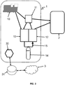
- the figure 2 represents a preferred embodiment of a system 1 for implementing the present method of supplying equipment 2.
- the equipment 2 can be any device or set of device consuming electricity. At any time, the equipment 2 consumes a consumed power P c (t) which can be variable, zero at certain times.
- System 1 is an autonomous station as mentioned above, made up of two main assemblies: an “electrical” assembly and a “chemical” assembly.
- the electrical assembly includes an intermittent electrical source 10, electrical storage means 11, as well as any additional electrical components (transformers, electrical protection systems, etc.).
- the intermittent electric source 10 is advantageously supplied by one or more sources of energy from renewable sources, i.e. the electric source advantageously consists of one or more electric generators supplied by renewable energies.
- the intermittent electrical source 10 thus comprises one or more photovoltaic panels and / or one or more wind turbines.
- the source 10 provides a variable power P F (t) , dependent on external physical phenomena (sun, wind, temperature, etc.) and thus not controllable. In other words, the source 10 consumes no fuel, and it will be understood that equipment of the type of the fuel cell 12 which will be described later (which consumes a chemical fuel) is not an intermittent electrical source 10 within the meaning of the present invention.
- the electrical storage means 11 generally serve as a “buffer” between the system 1 and the equipment 2. More specifically, they store and destock electricity so as to smooth the variations in power of the intermittent source 10. They are electrically connected to each of the other components 10, 12, 13 of the system 1.
- the electrical storage means 11 advantageously consist of at least one battery and / or at least one supercapacitor and / or at least one flywheel.
- the chemical assembly comprises at least one fuel cell 12 and at least one electrochemical unit for generating said fuel 13. These two elements are respectively capable of producing electricity by consuming a chemical fuel, and of produce said chemical fuel by consuming electricity.
- Each fuel cell 12 and each electrochemical unit 13 can comprise several cells implementing the chemical reaction.
- said chemical fuel is gaseous dihydrogen, but a person skilled in the art will know how to use other fuels for which compatible fuel cells exist, such as methanol, formic acid or boron hydride, etc.
- the fuel cell 12 is an electric generator in which said chemical fuel is oxidized on one electrode while an oxidant, oxidizing agent, in particular atmospheric oxygen, is reduced on the other electrode.
- an oxidant, oxidizing agent in particular atmospheric oxygen
- the product of the reaction is water.
- a fuel cell does not use combustion, which allows it to obtain very high yields.
- PEM proton exchange membrane
- the electrochemical unit for generating said fuel 13 is the component having the opposite role of the fuel cell 12: it consumes electricity to generate said chemical fuel.
- unit 13 produces it from water, which is naturally found in large quantities, typically by electrolysis, that is to say the implementation of chemical reactions thanks to a difference of electrical potential.
- At least one electrolyser it can be of different technologies, in particular with a proton exchange membrane.
- Such technology advantageously allows the electrochemical unit 13 and the fuel cell 12 to be a single reversible item of equipment.
- this reversible equipment produces dihydrogen if it is supplied with current, and produces current if it is supplied with dihydrogen. This greatly simplifies the structure of system 1, and greatly limits its size.
- the “chemical” assembly also includes “auxiliaries”, that is to say means for storing dihydrogen 14 (high pressure cylinders), if necessary a compressor, and a dihydrogen circuit 15 (to transfer the latter from unit 13 to battery 12 and / or to storage means 14).
- the circuit 15 connects this equipment 12, 13, and the bottles 15, the dihydrogen going back and forth).
- the system 1 also includes a control module 30 which controls each of the elements of the system 1. More specifically, the module 30 manages the electrical supply of the equipment 2 by controlling the activation / deactivation of each element and the routing of the 'electricity. For example, the module 30 checks whether the storage means 11 are charging or discharging.
- the module 30 is capable of knowing at any time the parameters of these elements (power supplied by the source 10, power consumed by the equipment 2, charge level of the storage means 11, quantity of gaseous dihydrogen available, etc.), so as to carry out the present method in the manner which will now be described.
- the control module 30 is typically an electronic card or a processor, advantageously connected to a communication network 3 as will be seen.
- the present method begins with a step (a) of determining a power balance of the system 1, denoted ⁇ P (t) as a function of the power consumed by the equipment 2, denoted P C (t), and the power supplied by the intermittent electric source 10, denoted P F (t).
- a step (b) the method sees the reception by the control module 30 of data representative of the stability of said power balance ⁇ P (t) during a safety period t SEC .
- the module 30 will, as will be seen, manage the components of the system 1 in an optimized manner and respectful of their integrity.
- control module 30 acts as a module for preprocessing data representative of the stability of said power balance.
- the present method mainly uses variations in the power balance as a reference quantity. As we will see, this allows an equally optimal energy management while improving the lifetime of these electrochemical cells.
- data representative of the stability of said power balance ⁇ P (t) is meant forecast data relating to the power P C (t) consumed by the equipment 2, and / or to the power P F (t) supplied by the intermittent power source 10.
- control module 30 can determine that the power balance ⁇ P (t) is not stable and will decrease.
- the “future” value (ie at the end of the safety period) of the power balance can possibly be estimated, but this is not imperative, only the stability assessment is required.
- Said safety period t SEC advantageously corresponds to a minimum recommended duration of continuous operation of the fuel cell 12 or of the electrochemical unit 13 to avoid its damage, hence its name “of security ". More precisely, it is a period before the expiration of which it is not desirable to change state again (activate / deactivate) the fuel cell 12 or the electrochemical unit 13 under penalty of causing premature aging.
- said safety period is typically between one and ten minutes.
- This data can be generic data obtained locally, for example of meteorological origin, which can indicate to what extent the means of production of renewable energy will be productive, but preferably it is more complex data provided from a communication network 3 (typically the internet network) in particular via a box 31, in particular in real time.
- a communication network 3 typically the internet network
- the forecast data may be data estimated by models, or simply the data from the previous day, or even an operating schedule for the equipment 2 if it is available.
- the box 31 is Internet access equipment of the “box” type from an Internet access provider (for example a 4G modem for autonomous operation), connected to the control module 30 by network connection means such as Wi-Fi, Ethernet or USB link, etc.
- the data may possibly simply be data preprocessed on servers of an electricity supplier operating system 1.
- the present invention is neither limited to a particular type of data representative of the stability of said power balance, nor to a way of providing these data.
- the module 30 controls the fuel cell 12 and the electrochemical unit 13 (and the other elements of the system 1) according to the power balance and its estimated stability, so as to supply the equipment 2 optimally.
- the electrochemical unit 13 is activated if (and advantageously only if) said power balance is greater than a first threshold and said data are not characteristic of an upcoming decrease in said power balance.
- the first threshold advantageously corresponds substantially to the power necessary for the operation of the electrochemical unit 13 (ie the power of the electrochemical unit 13 as well as that of its auxiliaries), denoted P H2 .
- the generation of hydrogen is only ordered if ⁇ P > P H2 , ie P F > P C + P H2 , that is to say if the source 10 provides sufficient power to supply both the equipment 2 and the electrochemical unit 13, but in a sustainable manner.
- the electrochemical unit 13 is not activated. This prevents it from being deactivated a few minutes later and the damage associated with this cut-off too soon after its activation (before the end of the safety period).
- the excess power (not used by the equipment 2) is used if possible to charge the storage means 11 (and in the worst case lost, but insofar as this does not may not last more than a few minutes, this is negligible).
- the fuel cell 12 is activated if (and advantageously only if, with a possible single exception which will be described later) said power balance is less than a second threshold less than the first threshold and said data does not are not characteristic of an imminent increase in said power balance.
- the second threshold is advantageously substantially zero.
- the consumption of hydrogen is only ordered if 0 ⁇ ⁇ P ie P F ⁇ P C , that is to say if the source 10 does not provide sufficient power to supply at least the equipment 2, but in a sustainable manner.
- the fuel cell 12 is not activated. This prevents it from being deactivated a few minutes later and the damage associated with this cut-off too soon after its activation (before the end of the safety period).
- the equipment 2 discharges the storage means 11 to recover the residual power P C - P F. Since this situation should not last more than a few minutes, the battery charge is normally largely sufficient.
- an emergency activation of the fuel cell 12 can still be provided even if said power balance is less than a second threshold less than the first threshold and said data are characteristic of an upcoming increase in said balance power ; if an amount of energy stored by the electrical storage means 11 is insufficient to supply the equipment 2 during said safety period.
- the fuel cell 12 is preferably deactivated (in the case of a previously active state) if (and advantageously only if) said power balance is greater than the second threshold and said data are not characteristic of an imminent drop in said power balance, that is to say if the source 10 provides sufficient power to supply at least the equipment 2, but in a sustainable manner.
- the electrochemical unit 13 is preferably deactivated (in the case of a previously active state) if (and advantageously only if, apart from a possible exception which will be described later) said power balance is less than the first threshold and said data are not characteristic of an imminent increase in said power balance, that is to say if the source 10 does not provide sufficient power to supply both equipment 2 and l electrochemical unit 13, but in a sustainable manner.
- the electrochemical unit 13 is not deactivated, ie remains activated. This prevents reactivation a few minutes later and the damage associated with this ignition too soon after deactivation (before the end of the safety period)
- the equipment 2 uses the energy of the intermittent source 10 while the electrochemical unit 13 discharges the storage means 11 to recover the remaining power P C + P H2 -P F. Since this situation should not last more than a few minutes, the battery charge is normally largely sufficient.
- an emergency deactivation of the electrochemical unit 13 can still be provided even if said power balance is less than the first threshold and said data are not characteristic of an upcoming increase in said power balance; if an amount of energy stored by the electrical storage means 11 is insufficient to supply the electrochemical unit 13 during said safety period.
- the invention relates to the system 1 implementing the method according to the first aspect of the invention.
- This system 1 comprises an intermittent electrical source 10, electrical storage means 11, a fuel cell 12, an electrochemical unit for generating said fuel 13 and a control module 30 (and where appropriate electrical or chemical auxiliaries).
Landscapes
- Engineering & Computer Science (AREA)
- Power Engineering (AREA)
- Sustainable Development (AREA)
- Life Sciences & Earth Sciences (AREA)
- Sustainable Energy (AREA)
- Chemical & Material Sciences (AREA)
- Chemical Kinetics & Catalysis (AREA)
- Electrochemistry (AREA)
- General Chemical & Material Sciences (AREA)
- Manufacturing & Machinery (AREA)
- Fuel Cell (AREA)
- Supply And Distribution Of Alternating Current (AREA)
- Charge And Discharge Circuits For Batteries Or The Like (AREA)
Applications Claiming Priority (2)
| Application Number | Priority Date | Filing Date | Title |
|---|---|---|---|
| FR1654835A FR3051987B1 (fr) | 2016-05-30 | 2016-05-30 | Procede d'alimentation electrique d'un equipement par une station autonome hybride |
| PCT/FR2017/051338 WO2017207910A1 (fr) | 2016-05-30 | 2017-05-30 | Procede d'alimentation electrique d'un equipement par une station autonome hybride |
Publications (2)
| Publication Number | Publication Date |
|---|---|
| EP3465861A1 EP3465861A1 (fr) | 2019-04-10 |
| EP3465861B1 true EP3465861B1 (fr) | 2020-05-13 |
Family
ID=57485567
Family Applications (1)
| Application Number | Title | Priority Date | Filing Date |
|---|---|---|---|
| EP17732511.5A Active EP3465861B1 (fr) | 2016-05-30 | 2017-05-30 | Procede d'alimentation electrique d'un equipement par une station autonome hybride |
Country Status (6)
| Country | Link |
|---|---|
| US (1) | US11271230B2 (enExample) |
| EP (1) | EP3465861B1 (enExample) |
| JP (1) | JP7046010B2 (enExample) |
| CN (1) | CN109196748B (enExample) |
| FR (1) | FR3051987B1 (enExample) |
| WO (1) | WO2017207910A1 (enExample) |
Families Citing this family (3)
| Publication number | Priority date | Publication date | Assignee | Title |
|---|---|---|---|---|
| JP7120055B2 (ja) * | 2019-01-30 | 2022-08-17 | トヨタ自動車株式会社 | 燃料電池システム |
| KR102228132B1 (ko) * | 2020-11-02 | 2021-03-17 | (주)시그넷이브이 | 수소연료전지차량 및 전기차량 충전을 위한 ess 시스템 |
| FR3134545A1 (fr) * | 2022-04-15 | 2023-10-20 | Powidian | Utilisation spécifique d’un véhicule à pile à combustible |
Family Cites Families (25)
| Publication number | Priority date | Publication date | Assignee | Title |
|---|---|---|---|---|
| EP0136187A3 (en) * | 1983-09-29 | 1986-10-22 | Engelhard Corporation | Fuel cell/battery hybrid system having battery charge-level control |
| JPH1146460A (ja) * | 1997-03-14 | 1999-02-16 | Toshiba Corp | 電力貯蔵システム |
| JP2004129314A (ja) * | 2000-03-17 | 2004-04-22 | Soichi Sato | 蓄電装置を備えた熱電併給システム |
| JP2002075388A (ja) * | 2000-08-25 | 2002-03-15 | Sekisui Chem Co Ltd | 給電システムの稼動方法および給電システム |
| JP4128792B2 (ja) * | 2002-03-28 | 2008-07-30 | 荏原バラード株式会社 | 燃料処理装置 |
| JP4594631B2 (ja) * | 2004-02-27 | 2010-12-08 | 株式会社東芝 | 燃料電池ユニットおよび燃料電池ユニットの制御方法 |
| JP2006345649A (ja) * | 2005-06-09 | 2006-12-21 | Hitachi Zosen Corp | 風力発電を利用した水電解水素発生装置およびその運転方法 |
| JP2008011614A (ja) * | 2006-06-28 | 2008-01-17 | Honda Motor Co Ltd | 水素生成システム |
| FR2907114B1 (fr) * | 2006-10-11 | 2009-07-10 | Electricite De France | Dispositif electrochimique comprenant un electrolyte ceramique conducteur de protons |
| KR20100061453A (ko) * | 2007-07-25 | 2010-06-07 | 트루라이트 인크. | 하이브리드 전력의 생성 및 사용을 관리하는 장치, 시스템 및 방법 |
| EP2048759A1 (fr) | 2007-10-09 | 2009-04-15 | EM Microelectronic-Marin SA | Installation de production et de stockage d'énergie renouvelable |
| US9231267B2 (en) * | 2009-02-17 | 2016-01-05 | Mcalister Technologies, Llc | Systems and methods for sustainable economic development through integrated full spectrum production of renewable energy |
| EP2639922B1 (en) * | 2010-11-10 | 2017-12-06 | Panasonic Intellectual Property Management Co., Ltd. | Operation planning method and operation planning device |
| FR2972867B1 (fr) | 2011-03-17 | 2014-02-07 | Cassidian Sas | Systeme d'alimentation electrique hybride autonome d'un equipement electrique et unite et procede de gestion du systeme |
| FI125987B (fi) * | 2011-06-30 | 2016-05-13 | Convion Oy | Menetelmä ja järjestely suojakaasujen tarpeen minimoimiseksi |
| DE102011055250A1 (de) * | 2011-11-10 | 2013-05-16 | Evonik Degussa Gmbh | Verfahren zur Erbringung von Regelleistung unter Verwendung von Energiespeichern |
| CN103219791B (zh) * | 2012-01-21 | 2015-07-01 | 电联运通股份有限公司 | 能源切换装置及方法 |
| FR2989225A1 (fr) * | 2012-04-10 | 2013-10-11 | Univ Rennes | Dispositif de pile a combustible a electrolytes circulants, par percolation a travers d'electrodes de structure tridimensionnelle poreuse |
| JP6005503B2 (ja) * | 2012-12-21 | 2016-10-12 | 株式会社東芝 | 水素電力供給システム |
| EP2953198B1 (en) * | 2013-01-31 | 2020-04-22 | Panasonic Intellectual Property Management Co., Ltd. | Fuel cell activation device, fuel cell activation method, and fuel cell activation system |
| JP2014216062A (ja) * | 2013-04-22 | 2014-11-17 | コニカミノルタ株式会社 | 2次電池型燃料電池システム及びそれを備えた給電システム |
| CN104734168B (zh) * | 2015-03-13 | 2017-01-25 | 山东大学 | 一种基于电热联合调度的微电网运行优化系统及方法 |
| CN105305506B (zh) * | 2015-09-29 | 2017-08-11 | 四川师范大学 | 一种多源复合型超导微电网系统及其能量管理方法 |
| CN105429173B (zh) * | 2015-11-23 | 2018-04-10 | 华北电力大学 | 一种基于燃料电池与风能的分布式能源系统 |
| DK3381102T3 (da) * | 2015-11-25 | 2021-08-09 | Hps Home Power Solutions Gmbh | Husenergianlæg og driftsfremgangsmåde til drift af et husenergianlæg |
-
2016
- 2016-05-30 FR FR1654835A patent/FR3051987B1/fr not_active Expired - Fee Related
-
2017
- 2017-05-30 WO PCT/FR2017/051338 patent/WO2017207910A1/fr not_active Ceased
- 2017-05-30 US US16/305,666 patent/US11271230B2/en active Active
- 2017-05-30 JP JP2018562642A patent/JP7046010B2/ja active Active
- 2017-05-30 CN CN201780033005.6A patent/CN109196748B/zh not_active Expired - Fee Related
- 2017-05-30 EP EP17732511.5A patent/EP3465861B1/fr active Active
Non-Patent Citations (1)
| Title |
|---|
| None * |
Also Published As
| Publication number | Publication date |
|---|---|
| EP3465861A1 (fr) | 2019-04-10 |
| JP7046010B2 (ja) | 2022-04-01 |
| FR3051987B1 (fr) | 2018-05-18 |
| WO2017207910A1 (fr) | 2017-12-07 |
| CN109196748A (zh) | 2019-01-11 |
| JP2019518407A (ja) | 2019-06-27 |
| CN109196748B (zh) | 2022-04-15 |
| US11271230B2 (en) | 2022-03-08 |
| US20200328440A1 (en) | 2020-10-15 |
| FR3051987A1 (fr) | 2017-12-01 |
Similar Documents
| Publication | Publication Date | Title |
|---|---|---|
| EP2686934B1 (fr) | Système d'alimentation électrique hybride autonome d'un équipement électrique et unité et procédé de gestion du système | |
| EP2206209B1 (fr) | Installation de production et de stockage d'énergie renouvelable | |
| EP2535996B1 (fr) | Mécanisme de commande sécurisé pour système photovoltaïque distribué | |
| FR2998719A1 (fr) | Batterie metal-air avec dispositif de controle du potentiel de l'electrode negative | |
| EP3465861B1 (fr) | Procede d'alimentation electrique d'un equipement par une station autonome hybride | |
| FR2998718A1 (fr) | Procede de charge d'une batterie zinc-air a potentiel limite | |
| EP2774210B1 (fr) | Procede de gestion du fonctionnement d'un systeme hybride | |
| EP2494672A2 (fr) | Gestion de la recharge d'un parc de batteries | |
| EP3009531A1 (fr) | Procede de pilotage d'un systeme d'electrolyse prenant en compte la temperature des modules electrolyseurs dudit systeme d'electrolyse | |
| EP2530780A1 (fr) | Procédé de gestion du fonctionnement d'un système hybride | |
| EP3005453A1 (fr) | Procédé de maintien des performances d'un système à pile à combustible, et circuit gaz d'une pile à combustible | |
| FR2964265A1 (fr) | Procede de charge d'une batterie electrique | |
| EP3637582B1 (fr) | Installation de stockage de l'énergie électrique issue du freinage d'un ou plusieurs véhicules ferroviaires et système de stockage associé | |
| EP2772983B1 (fr) | Dispositif de stockage d'énergie et procédé de gestion associé | |
| WO2008068440A1 (fr) | Dispositif d'alimentation pour une machine electrique de vehicule electrique a deux sources d'energie complementaires l'une de l'autre | |
| EP2560261A1 (fr) | Procede de gestion d'une installation de production et de stockage d'energie renouvelable | |
| EP1829152B1 (fr) | Procede pour maintenir un accumulateur au plomb charge | |
| WO2019011898A1 (fr) | Procédé de gestion de l'énergie électrique transitant dans une batterie métal-air et cellule associée | |
| FR3144718A1 (fr) | Installation électrique |
Legal Events
| Date | Code | Title | Description |
|---|---|---|---|
| STAA | Information on the status of an ep patent application or granted ep patent |
Free format text: STATUS: UNKNOWN |
|
| STAA | Information on the status of an ep patent application or granted ep patent |
Free format text: STATUS: THE INTERNATIONAL PUBLICATION HAS BEEN MADE |
|
| PUAI | Public reference made under article 153(3) epc to a published international application that has entered the european phase |
Free format text: ORIGINAL CODE: 0009012 |
|
| STAA | Information on the status of an ep patent application or granted ep patent |
Free format text: STATUS: REQUEST FOR EXAMINATION WAS MADE |
|
| 17P | Request for examination filed |
Effective date: 20181220 |
|
| AK | Designated contracting states |
Kind code of ref document: A1 Designated state(s): AL AT BE BG CH CY CZ DE DK EE ES FI FR GB GR HR HU IE IS IT LI LT LU LV MC MK MT NL NO PL PT RO RS SE SI SK SM TR |
|
| AX | Request for extension of the european patent |
Extension state: BA ME |
|
| DAV | Request for validation of the european patent (deleted) | ||
| DAX | Request for extension of the european patent (deleted) | ||
| REG | Reference to a national code |
Ref country code: DE Ref legal event code: R079 Ref document number: 602017016573 Country of ref document: DE Free format text: PREVIOUS MAIN CLASS: H02J0001100000 Ipc: H02J0003320000 |
|
| GRAP | Despatch of communication of intention to grant a patent |
Free format text: ORIGINAL CODE: EPIDOSNIGR1 |
|
| STAA | Information on the status of an ep patent application or granted ep patent |
Free format text: STATUS: GRANT OF PATENT IS INTENDED |
|
| RIC1 | Information provided on ipc code assigned before grant |
Ipc: H01M 16/00 20060101ALI20191122BHEP Ipc: H02J 1/10 20060101ALI20191122BHEP Ipc: H02J 3/38 20060101ALI20191122BHEP Ipc: H02J 3/32 20060101AFI20191122BHEP Ipc: H02J 3/28 20060101ALI20191122BHEP Ipc: H02J 15/00 20060101ALI20191122BHEP Ipc: H01M 8/04537 20160101ALI20191122BHEP Ipc: H02J 1/00 20060101ALI20191122BHEP |
|
| INTG | Intention to grant announced |
Effective date: 20191210 |
|
| GRAS | Grant fee paid |
Free format text: ORIGINAL CODE: EPIDOSNIGR3 |
|
| GRAA | (expected) grant |
Free format text: ORIGINAL CODE: 0009210 |
|
| STAA | Information on the status of an ep patent application or granted ep patent |
Free format text: STATUS: THE PATENT HAS BEEN GRANTED |
|
| AK | Designated contracting states |
Kind code of ref document: B1 Designated state(s): AL AT BE BG CH CY CZ DE DK EE ES FI FR GB GR HR HU IE IS IT LI LT LU LV MC MK MT NL NO PL PT RO RS SE SI SK SM TR |
|
| REG | Reference to a national code |
Ref country code: GB Ref legal event code: FG4D Free format text: NOT ENGLISH |
|
| REG | Reference to a national code |
Ref country code: CH Ref legal event code: EP |
|
| REG | Reference to a national code |
Ref country code: DE Ref legal event code: R096 Ref document number: 602017016573 Country of ref document: DE |
|
| REG | Reference to a national code |
Ref country code: AT Ref legal event code: REF Ref document number: 1271513 Country of ref document: AT Kind code of ref document: T Effective date: 20200615 |
|
| REG | Reference to a national code |
Ref country code: LT Ref legal event code: MG4D |
|
| REG | Reference to a national code |
Ref country code: NL Ref legal event code: MP Effective date: 20200513 |
|
| PG25 | Lapsed in a contracting state [announced via postgrant information from national office to epo] |
Ref country code: LT Free format text: LAPSE BECAUSE OF FAILURE TO SUBMIT A TRANSLATION OF THE DESCRIPTION OR TO PAY THE FEE WITHIN THE PRESCRIBED TIME-LIMIT Effective date: 20200513 Ref country code: FI Free format text: LAPSE BECAUSE OF FAILURE TO SUBMIT A TRANSLATION OF THE DESCRIPTION OR TO PAY THE FEE WITHIN THE PRESCRIBED TIME-LIMIT Effective date: 20200513 Ref country code: GR Free format text: LAPSE BECAUSE OF FAILURE TO SUBMIT A TRANSLATION OF THE DESCRIPTION OR TO PAY THE FEE WITHIN THE PRESCRIBED TIME-LIMIT Effective date: 20200814 Ref country code: NO Free format text: LAPSE BECAUSE OF FAILURE TO SUBMIT A TRANSLATION OF THE DESCRIPTION OR TO PAY THE FEE WITHIN THE PRESCRIBED TIME-LIMIT Effective date: 20200813 Ref country code: SE Free format text: LAPSE BECAUSE OF FAILURE TO SUBMIT A TRANSLATION OF THE DESCRIPTION OR TO PAY THE FEE WITHIN THE PRESCRIBED TIME-LIMIT Effective date: 20200513 Ref country code: PT Free format text: LAPSE BECAUSE OF FAILURE TO SUBMIT A TRANSLATION OF THE DESCRIPTION OR TO PAY THE FEE WITHIN THE PRESCRIBED TIME-LIMIT Effective date: 20200914 Ref country code: IS Free format text: LAPSE BECAUSE OF FAILURE TO SUBMIT A TRANSLATION OF THE DESCRIPTION OR TO PAY THE FEE WITHIN THE PRESCRIBED TIME-LIMIT Effective date: 20200913 |
|
| PG25 | Lapsed in a contracting state [announced via postgrant information from national office to epo] |
Ref country code: LV Free format text: LAPSE BECAUSE OF FAILURE TO SUBMIT A TRANSLATION OF THE DESCRIPTION OR TO PAY THE FEE WITHIN THE PRESCRIBED TIME-LIMIT Effective date: 20200513 Ref country code: HR Free format text: LAPSE BECAUSE OF FAILURE TO SUBMIT A TRANSLATION OF THE DESCRIPTION OR TO PAY THE FEE WITHIN THE PRESCRIBED TIME-LIMIT Effective date: 20200513 Ref country code: BG Free format text: LAPSE BECAUSE OF FAILURE TO SUBMIT A TRANSLATION OF THE DESCRIPTION OR TO PAY THE FEE WITHIN THE PRESCRIBED TIME-LIMIT Effective date: 20200813 Ref country code: RS Free format text: LAPSE BECAUSE OF FAILURE TO SUBMIT A TRANSLATION OF THE DESCRIPTION OR TO PAY THE FEE WITHIN THE PRESCRIBED TIME-LIMIT Effective date: 20200513 |
|
| REG | Reference to a national code |
Ref country code: DE Ref legal event code: R082 Ref document number: 602017016573 Country of ref document: DE Representative=s name: MAIWALD PATENTANWALTS- UND RECHTSANWALTSGESELL, DE Ref country code: DE Ref legal event code: R081 Ref document number: 602017016573 Country of ref document: DE Owner name: UNIVERSITE D'ORLEANS, FR Free format text: FORMER OWNERS: CENTRE NATIONAL DE LA RECHERCHE SCIENTIFIQUE (CNRS), PARIS, FR; CRESITT INDUSTRIE, OLIVET CEDEX, FR; UNIVERSITE D'ORLEANS, ORLEANS, FR Ref country code: DE Ref legal event code: R081 Ref document number: 602017016573 Country of ref document: DE Owner name: CENTRE NATIONAL DE LA RECHERCHE SCIENTIFIQUE (, FR Free format text: FORMER OWNERS: CENTRE NATIONAL DE LA RECHERCHE SCIENTIFIQUE (CNRS), PARIS, FR; CRESITT INDUSTRIE, OLIVET CEDEX, FR; UNIVERSITE D'ORLEANS, ORLEANS, FR |
|
| REG | Reference to a national code |
Ref country code: AT Ref legal event code: MK05 Ref document number: 1271513 Country of ref document: AT Kind code of ref document: T Effective date: 20200513 |
|
| RAP2 | Party data changed (patent owner data changed or rights of a patent transferred) |
Owner name: UNIVERSITE D'ORLEANS Owner name: CENTRE NATIONAL DE LA RECHERCHE SCIENTIFIQUE (CNRS) |
|
| PG25 | Lapsed in a contracting state [announced via postgrant information from national office to epo] |
Ref country code: NL Free format text: LAPSE BECAUSE OF FAILURE TO SUBMIT A TRANSLATION OF THE DESCRIPTION OR TO PAY THE FEE WITHIN THE PRESCRIBED TIME-LIMIT Effective date: 20200513 Ref country code: AL Free format text: LAPSE BECAUSE OF FAILURE TO SUBMIT A TRANSLATION OF THE DESCRIPTION OR TO PAY THE FEE WITHIN THE PRESCRIBED TIME-LIMIT Effective date: 20200513 |
|
| RAP2 | Party data changed (patent owner data changed or rights of a patent transferred) |
Owner name: UNIVERSITE D'ORLEANS Owner name: CENTRE NATIONAL DE LA RECHERCHE SCIENTIFIQUE (CNRS) Owner name: CRESITT INDUSTRIE |
|
| PG25 | Lapsed in a contracting state [announced via postgrant information from national office to epo] |
Ref country code: CZ Free format text: LAPSE BECAUSE OF FAILURE TO SUBMIT A TRANSLATION OF THE DESCRIPTION OR TO PAY THE FEE WITHIN THE PRESCRIBED TIME-LIMIT Effective date: 20200513 Ref country code: RO Free format text: LAPSE BECAUSE OF FAILURE TO SUBMIT A TRANSLATION OF THE DESCRIPTION OR TO PAY THE FEE WITHIN THE PRESCRIBED TIME-LIMIT Effective date: 20200513 Ref country code: DK Free format text: LAPSE BECAUSE OF FAILURE TO SUBMIT A TRANSLATION OF THE DESCRIPTION OR TO PAY THE FEE WITHIN THE PRESCRIBED TIME-LIMIT Effective date: 20200513 Ref country code: EE Free format text: LAPSE BECAUSE OF FAILURE TO SUBMIT A TRANSLATION OF THE DESCRIPTION OR TO PAY THE FEE WITHIN THE PRESCRIBED TIME-LIMIT Effective date: 20200513 Ref country code: CH Free format text: LAPSE BECAUSE OF NON-PAYMENT OF DUE FEES Effective date: 20200531 Ref country code: SM Free format text: LAPSE BECAUSE OF FAILURE TO SUBMIT A TRANSLATION OF THE DESCRIPTION OR TO PAY THE FEE WITHIN THE PRESCRIBED TIME-LIMIT Effective date: 20200513 Ref country code: AT Free format text: LAPSE BECAUSE OF FAILURE TO SUBMIT A TRANSLATION OF THE DESCRIPTION OR TO PAY THE FEE WITHIN THE PRESCRIBED TIME-LIMIT Effective date: 20200513 Ref country code: LI Free format text: LAPSE BECAUSE OF NON-PAYMENT OF DUE FEES Effective date: 20200531 Ref country code: ES Free format text: LAPSE BECAUSE OF FAILURE TO SUBMIT A TRANSLATION OF THE DESCRIPTION OR TO PAY THE FEE WITHIN THE PRESCRIBED TIME-LIMIT Effective date: 20200513 |
|
| REG | Reference to a national code |
Ref country code: GB Ref legal event code: 732E Free format text: REGISTERED BETWEEN 20210107 AND 20210113 |
|
| REG | Reference to a national code |
Ref country code: DE Ref legal event code: R097 Ref document number: 602017016573 Country of ref document: DE |
|
| PG25 | Lapsed in a contracting state [announced via postgrant information from national office to epo] |
Ref country code: SK Free format text: LAPSE BECAUSE OF FAILURE TO SUBMIT A TRANSLATION OF THE DESCRIPTION OR TO PAY THE FEE WITHIN THE PRESCRIBED TIME-LIMIT Effective date: 20200513 Ref country code: MC Free format text: LAPSE BECAUSE OF FAILURE TO SUBMIT A TRANSLATION OF THE DESCRIPTION OR TO PAY THE FEE WITHIN THE PRESCRIBED TIME-LIMIT Effective date: 20200513 Ref country code: PL Free format text: LAPSE BECAUSE OF FAILURE TO SUBMIT A TRANSLATION OF THE DESCRIPTION OR TO PAY THE FEE WITHIN THE PRESCRIBED TIME-LIMIT Effective date: 20200513 |
|
| PLBE | No opposition filed within time limit |
Free format text: ORIGINAL CODE: 0009261 |
|
| REG | Reference to a national code |
Ref country code: BE Ref legal event code: MM Effective date: 20200531 |
|
| STAA | Information on the status of an ep patent application or granted ep patent |
Free format text: STATUS: NO OPPOSITION FILED WITHIN TIME LIMIT |
|
| PG25 | Lapsed in a contracting state [announced via postgrant information from national office to epo] |
Ref country code: LU Free format text: LAPSE BECAUSE OF NON-PAYMENT OF DUE FEES Effective date: 20200530 |
|
| 26N | No opposition filed |
Effective date: 20210216 |
|
| PG25 | Lapsed in a contracting state [announced via postgrant information from national office to epo] |
Ref country code: IE Free format text: LAPSE BECAUSE OF NON-PAYMENT OF DUE FEES Effective date: 20200530 |
|
| PG25 | Lapsed in a contracting state [announced via postgrant information from national office to epo] |
Ref country code: BE Free format text: LAPSE BECAUSE OF NON-PAYMENT OF DUE FEES Effective date: 20200531 Ref country code: SI Free format text: LAPSE BECAUSE OF FAILURE TO SUBMIT A TRANSLATION OF THE DESCRIPTION OR TO PAY THE FEE WITHIN THE PRESCRIBED TIME-LIMIT Effective date: 20200513 |
|
| PG25 | Lapsed in a contracting state [announced via postgrant information from national office to epo] |
Ref country code: TR Free format text: LAPSE BECAUSE OF FAILURE TO SUBMIT A TRANSLATION OF THE DESCRIPTION OR TO PAY THE FEE WITHIN THE PRESCRIBED TIME-LIMIT Effective date: 20200513 Ref country code: MT Free format text: LAPSE BECAUSE OF FAILURE TO SUBMIT A TRANSLATION OF THE DESCRIPTION OR TO PAY THE FEE WITHIN THE PRESCRIBED TIME-LIMIT Effective date: 20200513 Ref country code: CY Free format text: LAPSE BECAUSE OF FAILURE TO SUBMIT A TRANSLATION OF THE DESCRIPTION OR TO PAY THE FEE WITHIN THE PRESCRIBED TIME-LIMIT Effective date: 20200513 |
|
| PG25 | Lapsed in a contracting state [announced via postgrant information from national office to epo] |
Ref country code: MK Free format text: LAPSE BECAUSE OF FAILURE TO SUBMIT A TRANSLATION OF THE DESCRIPTION OR TO PAY THE FEE WITHIN THE PRESCRIBED TIME-LIMIT Effective date: 20200513 |
|
| PGFP | Annual fee paid to national office [announced via postgrant information from national office to epo] |
Ref country code: DE Payment date: 20250626 Year of fee payment: 9 |
|
| PGFP | Annual fee paid to national office [announced via postgrant information from national office to epo] |
Ref country code: GB Payment date: 20250528 Year of fee payment: 9 |
|
| PGFP | Annual fee paid to national office [announced via postgrant information from national office to epo] |
Ref country code: IT Payment date: 20250528 Year of fee payment: 9 |
|
| PGFP | Annual fee paid to national office [announced via postgrant information from national office to epo] |
Ref country code: FR Payment date: 20250528 Year of fee payment: 9 |