EP3465612B1 - Verfahren und vorrichtung zur erkennung von schaum in probenbehältern - Google Patents
Verfahren und vorrichtung zur erkennung von schaum in probenbehältern Download PDFInfo
- Publication number
- EP3465612B1 EP3465612B1 EP17803689.3A EP17803689A EP3465612B1 EP 3465612 B1 EP3465612 B1 EP 3465612B1 EP 17803689 A EP17803689 A EP 17803689A EP 3465612 B1 EP3465612 B1 EP 3465612B1
- Authority
- EP
- European Patent Office
- Prior art keywords
- container
- specimen container
- specimen
- imaging
- automated
- Prior art date
- Legal status (The legal status is an assumption and is not a legal conclusion. Google has not performed a legal analysis and makes no representation as to the accuracy of the status listed.)
- Active
Links
Images














Classifications
-
- G—PHYSICS
- G06—COMPUTING OR CALCULATING; COUNTING
- G06T—IMAGE DATA PROCESSING OR GENERATION, IN GENERAL
- G06T7/00—Image analysis
- G06T7/0002—Inspection of images, e.g. flaw detection
- G06T7/0004—Industrial image inspection
-
- G—PHYSICS
- G01—MEASURING; TESTING
- G01F—MEASURING VOLUME, VOLUME FLOW, MASS FLOW OR LIQUID LEVEL; METERING BY VOLUME
- G01F23/00—Indicating or measuring liquid level or level of fluent solid material, e.g. indicating in terms of volume or indicating by means of an alarm
- G01F23/80—Arrangements for signal processing
- G01F23/802—Particular electronic circuits for digital processing equipment
-
- G—PHYSICS
- G01—MEASURING; TESTING
- G01N—INVESTIGATING OR ANALYSING MATERIALS BY DETERMINING THEIR CHEMICAL OR PHYSICAL PROPERTIES
- G01N21/00—Investigating or analysing materials by the use of optical means, i.e. using sub-millimetre waves, infrared, visible or ultraviolet light
- G01N21/84—Systems specially adapted for particular applications
- G01N21/88—Investigating the presence of flaws or contamination
- G01N21/90—Investigating the presence of flaws or contamination in a container or its contents
-
- G—PHYSICS
- G01—MEASURING; TESTING
- G01N—INVESTIGATING OR ANALYSING MATERIALS BY DETERMINING THEIR CHEMICAL OR PHYSICAL PROPERTIES
- G01N21/00—Investigating or analysing materials by the use of optical means, i.e. using sub-millimetre waves, infrared, visible or ultraviolet light
- G01N21/84—Systems specially adapted for particular applications
- G01N21/88—Investigating the presence of flaws or contamination
- G01N21/90—Investigating the presence of flaws or contamination in a container or its contents
- G01N21/9018—Dirt detection in containers
- G01N21/9027—Dirt detection in containers in containers after filling
-
- G—PHYSICS
- G01—MEASURING; TESTING
- G01N—INVESTIGATING OR ANALYSING MATERIALS BY DETERMINING THEIR CHEMICAL OR PHYSICAL PROPERTIES
- G01N35/00—Automatic analysis not limited to methods or materials provided for in any single one of groups G01N1/00 - G01N33/00; Handling materials therefor
- G01N35/10—Devices for transferring samples or any liquids to, in, or from, the analysis apparatus, e.g. suction devices, injection devices
- G01N35/1009—Characterised by arrangements for controlling the aspiration or dispense of liquids
- G01N35/1016—Control of the volume dispensed or introduced
-
- G—PHYSICS
- G01—MEASURING; TESTING
- G01N—INVESTIGATING OR ANALYSING MATERIALS BY DETERMINING THEIR CHEMICAL OR PHYSICAL PROPERTIES
- G01N35/00—Automatic analysis not limited to methods or materials provided for in any single one of groups G01N1/00 - G01N33/00; Handling materials therefor
- G01N35/10—Devices for transferring samples or any liquids to, in, or from, the analysis apparatus, e.g. suction devices, injection devices
- G01N35/1009—Characterised by arrangements for controlling the aspiration or dispense of liquids
- G01N35/1016—Control of the volume dispensed or introduced
- G01N2035/1018—Detecting inhomogeneities, e.g. foam, bubbles, clots
-
- G—PHYSICS
- G06—COMPUTING OR CALCULATING; COUNTING
- G06T—IMAGE DATA PROCESSING OR GENERATION, IN GENERAL
- G06T2207/00—Indexing scheme for image analysis or image enhancement
- G06T2207/10—Image acquisition modality
- G06T2207/10024—Color image
Definitions
- the present invention is directed to an automated method and apparatus for detecting foam in a specimen container, which will be tested for the presence of a microbial agent or microorganism. Moreover, the automated system builds upon and improves existing detection systems for processing specimen containers, such as culture bottles.
- the detection of pathogenic microorganisms in biological fluids should be performed in the shortest possible time, in particular in the case of septicemia for which the mortality remains high in spite of the broad range of antibiotics which are available to doctors.
- the presence of biologically active agents such as a microorganism in a patient's body fluid, especially blood is generally determined using blood culture bottles. A small quantity of blood is injected through an enclosing rubber septum into a sterile bottle containing a culture medium, and the bottle is then incubated at 37° C and monitored for microorganism growth.
- One such instrument is the BacT/ALERT ® 3D instrument of the present assignee bioMérieux, Inc.
- the instrument receives a blood culture bottle containing a blood sample, e.g., from a human patient.
- the instrument incubates the bottle and periodically during incubation an optical detection unit in the incubator analyzes a colorimetric sensor incorporated into the bottle to detect whether microbial growth has occurred within the bottle.
- the optical detection unit, bottles and sensors are described in the patent literature, see U.S.
- Non-clinical samples that may be tested include, but not limited to, foodstuffs, beverages, pharmaceuticals, cosmetics, water (e.g., drinking water, non-potable water, and waste water), seawater ballasts, air, soil, sewage, plant material (e.g., seeds, leaves, stems, roots, flowers, fruit), blood products (e.g., platelets, serum, plasma, white blood cell fractions, etc.), donor organ or tissue samples, biowarfare samples, and the like.
- the biological sample tested is a blood sample.
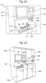
- the lower section 170 may have a larger profile or footprint than the upper section 160.
- the housing of the larger lower section 170 forms a shelf 180 on a top surface of the lower section 170 and adjacent to or in front of the upper section 160.
- This shelf 180 may provide a user workstation and/or workflow access points to the detection system 100.
- the shelf 180 may comprise an automated loading means or mechanism 200.
- the shelf 180 may further provide access locations for the first port or container entrance location 110, the second port or misread/error location 120, and the third port or positive container exit location 130.
- the automated detection system 100 may contain one or more work-flow stations 404 for obtaining one or more measurements, readings, scans and/or images of a specimen container, thereby providing information, such as, container type, container lot number, container expiration date, patient information, sample type, test type, fill level, weight measurement, etc.
- the one or more work-flow stations 404 may comprise one or more container management stations, such as, a container pick-up station or a container transfer station.
- the automated detection system may contain one or more of the following work-flow stations: (1) a bar code reading station; (2) a container scanning stations; (3) a container imaging station; (4) a container weighing station; (5) container pick-up station; and/or (6) a container transfer station.
- the detection system 100 may further have a container management means or container locator device 400, as shown, for example, in FIGS. 13-15 , 18 and 24 .
- the container management device or locator device 400 operates to move or otherwise locate a specimen container 500 to one or more work-flow stations 404.
- one or more of the work-flow stations are included within the housing 102 of the detection system 100. In one embodiment, as best shown in FIGS.
- the drum or drum-like loading device 308 and vertically orientated chute 332 of automated loading mechanism 300 can be operated to deposit or place a specimen container into a locator well 402, as described elsewhere herein.
- the transport mechanism 204, or conveyor belt 206, of automated loading mechanism 200 can operate to deposit or place a specimen container into a locator well 402, as described elsewhere herein.
- the detection system 100 may further comprise one or more guide rails (not shown) to guide the specimen container into the locator well 402.
- the container management device or locating device 400 can then rotate to move or locate the specimen container among various work-flow stations 404 within the system, such as for example, a bar code reading station, a container scanning stations, a container imaging station, a container weighing station, container pick-up station, and/or a container transfer station.
- various work-flow stations 404 such as for example, a bar code reading station, a container scanning stations, a container imaging station, a container weighing station, container pick-up station, and/or a container transfer station.
- the container management device or locator device 400 is described in greater detail herein.
- the detection system 100 may also comprise an automated transfer means or mechanism 650 for transferring the specimen containers 500 within the housing 102 of the detection system 100.
- the transfer mechanism 650 may transfer the specimen container 500 from an entrance location or port 110 (see, e.g., FIGS. 1-3 ), into the interior chamber 620 of the detection system 100, and place the container 500 into one of the receiving structures or wells 602 contained in one of a plurality of holding structures or racks 600.
- the transfer mechanism 650 may also be used to rearrange, transfer or otherwise manage specimen containers 500 within the system.
- the transfer mechanism 650 can be used to transfer a specimen container 500, detected as positive for microbial growth (referred to herein as a "positive" container), from the holding structure or rack 600 to a positive container location, such as a positive container exit location or port 130 (see, e.g., FIG. 1 ) where a user or technician can easily remove the positive container 500 from the detection system 100.
- the transfer mechanism 650 can be used to transfer a container 500 determined as negative for microbial growth after a designated time has passed (referred to herein as a "negative" container), from the holding structure or rack 600 to a negative container location within the system (e.g., a negative container waste bin 146 (see, e.g., FIG.
- the detection system 100 will also include a means for detecting growth (e.g., a detection unit) in the specimen containers 500 (see, e.g., Figure 27 ).
- a means for detecting growth e.g., a detection unit
- each holding station or rack 600 may contain a linear scanning optical system that has the capability of non-invasive monitoring of microorganism growth in each specimen container 500.
- the optical system can interrogate a sensor (e.g., a Liquid Emulsion Sensor (LES) sensor) 514 (see, e.g., FIG. 4 ) in the containers 500, thereby detecting for microorganism growth within the container.
- LES Liquid Emulsion Sensor
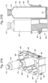
- the specimen container 500 shown for example in FIGS. 4 and 27B , and other figures, is shown in the form of a standard culture bottle (e.g., a blood culture bottle). However, the description of a culture bottle (e.g., a blood culture bottle) is offered by way of example and not limitation.
- the specimen container 500 comprises a top portion 502, a body 504, and a base 506.
- the container 500 may include a bar code label 508 for automated reading of the container 500 within either the detection system or off-line equipment.
- the top portion 502 of the container 500 typically comprises a narrow portion or neck 510 through which an opening 516 extends to provide communication with the interior chamber 518 of the container.
- the container also includes a closure device 512 (e.g., a stopper), optionally having a pierceable septum and may also have a sensor 514 (e.g., an LES sensor) formed or placed in the bottom of the container 500 for purposes of colorimetric detection of the presence of microbial growth in the container 500.
- a closure device 512 e.g., a stopper
- a sensor 514 e.g., an LES sensor
- the configuration of the container 500 is not particular important and the inventive system and methods can be adapted to a variety of containers designed for culturing a test sample (e.g., a biological test sample).
- Containers 500 of the type shown in FIGS. 4 and 27B are well known in the art and described in the patent literature cited in the Background section of this document.
- the specimen containers 500 are inoculated with a test sample (e.g., a clinical or non-clinical biological sample) and are loaded/unloaded into/out of the detection system 100.
- the container 500 may further comprise a growth or culture medium (not shown) for promoting and/or enhancing microbial or microorganism growth.
- a growth or culture media or medium for the cultivation of microorganisms is well known.
- a suitable growth or culture medium provides the proper nutritional and environmental conditions for growth of microorganisms and should contain all the nutrients required by the microorganism which is to be cultivated in the specimen container 500.
- the container 500 is tested within the detection system 100 for the presence of microbial or microorganism growth.
- the testing may occur continuously or on a periodic basis so that the container can be determined as positive for microorganism growth as soon as possible.
- the detection system 100 may include a means or mechanism for automated loading of a specimen container 500 into the detection system 100.
- the automated loading mechanism 200 may comprise a container loading station or area 202, a transport mechanism 204 and an entrance location or port 110.
- the automated loading mechanism can take on many different configurations.
- another design configuration of an automated loading mechanism 300 is described herein in conjunction with FIGS. 13-16 .
- the various design configurations described herein are by way of illustration and not limitation.
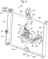
- the automated loading mechanisms shown herein (e.g., FIGS. 1-3 , 5A-5B and 13-16 ) are shown schematically and the parts are not to scale.
- a user or technician can transport one or more specimen containers 500 to the detection system 100 by any means and place the containers 500 at a container loading station or area 202.
- a user or technician can use a carrier designed to transport a plurality of specimen containers to the loading station or area 202 of the detection system 100.
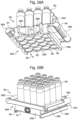
- the carrier 350 comprises a body 351 having top and bottom surfaces 352A and 352B, respectively, front and back surfaces 354A and 354B, respectively, opposing side surfaces 356A and 356B (e.g., a right side surface and left side surface), respectively, and a pair of opposing user handles 358A and 358B, attached to said opposing side surfaces 356A, 356B.
- the body further comprises a plurality of through holes 360, each configured to hold a single specimen container 500 therein.
- the body 351 may also comprise a slide plate 362 operable within a slide joint 364 to slide back-and-forth (see, e.g., arrow 366 in FIG. 28A ) between a "closed” position, to retain the specimen containers 500 loaded within the carrier 350, and an "open” position, to release the specimen containers 500 from the carrier 350, and deposit them onto or into an automated loading mechanism.
- the slide joint 364 may further comprise a spring, or like means, for locking the slide plate 362 in the "closed” position during transport by a user to a detection system.
- the carrier 350 may further comprise a pair of alignment arms 368A and 368B and a release tab 370 operable with a release mechanism 372 for releasing the specimen containers 500 at an automated loading mechanism 200 of a detection system 100.
- the release mechanism 372 comprises a pair of slots 374 that correspond to the pair of alignment arms 368A and 368B, to ensure the carrier 350 is properly aligned at the loading station or area 202 for depositing the specimen containers 500, and a release bar 376.
- a technician transports a carrier 350, containing one or more specimen containers 500, to the automated loading mechanism 200 and presses the carrier 350 against the release bar 376, with the alignment arms 368A and 368B aligned with the corresponding slots 374 of the release mechanism 372.
- the release tab 370 is pushed in or depressed, thereby moving the slide plate 362 to the "open" position and allowing the specimen containers 500 to fall out of the through holes 360 and onto the loading station or area 202.
- the technician can then lift the carrier 350 upward until the carrier body 351 and plurality of through holes 360 clear the specimen containers 500, thereby depositing the containers at the automated loading mechanism 200 for automated loading into the detection system 100.
- the carrier 350 containing one or more specimen containers 500
- the loading station or area 202 is typically an easily accessible location or area of the automated loading mechanism 200 where a user or technician can place one or more specimen containers 500 for loading into the detection system 100.
- the containers 500 will be transported, using a transport mechanism 204, from the loading station or area 202 to an entrance location or port 110, and subsequently through the entrance location or port 110 and into the detection system 100.
- a user or technician can simply place one or more specimen containers 500 at the loading station or area 202 and walk away, while the containers 500 are automatically loaded into the detection system 100.
- the specimen containers 500 Once the specimen containers 500 have been transported into the system, they can be moved to one or more work-flow stations using a container management device or locator device, and/or transferred to a holding structure or rack, as described elsewhere herein.
- the transport mechanism 204 is a conveyor belt 206 operable to transport (e.g., convey) the containers 500 to an entrance location or port 110 and subsequently through the entrance location or port 110 and into the detection system 100.
- transport e.g., convey
- other means or mechanisms for transporting the specimen containers 500 from the loading station or area 202 to the entrance location or port 110 are envisioned, and may include, but are not limited to, feed screws, timing belts having grooves or molded plates, and the like.
- the process of automated loading of a specimen container 500 into the detection system 100 may further comprise transferring the container to a holding structure or rack using a transfer mechanism 650 or moving the container to one or more work-flow stations using a container locator device (see, e.g., FIG. 24 , 400A), as described below.
- the loading station or area 202 and transport mechanism 204 comprise a conveyor belt 206.
- the user or technician can place one or more specimen containers 500 at a specific location or area (i.e., the loading station or area 202) of the conveyor belt 206 for automated loading of the containers 500 into the detection system 100.
- the conveyor belt 206 may run continuously, or may be activated by the physical presence of the container 500 at the loading station or area 202.
- a system controller can be used to operate the conveyor belt 206 (i.e., turn it on or off) based on a signal (e.g., a light sensor) indicating the presence, or absence, of one or more specimen containers at the loading station 202.
- a signal e.g., a light sensor
- one or more sensors can be used at the entrance location or port 110 to indicate if a container is improperly loaded and/or has fallen over and may cause jamming.
- the conveyor belt 206 operates to move or transport the containers 500 from the loading station or area 202 (e.g., the left portion of the conveyor belt 206, as shown in FIG. 1 ) to the entrance location or port 110, thereby accumulating one or more containers 500 at the entrance location or port 110 to be loaded into the detection system 100.
- the loading station or area 202, transport mechanism 204 or conveyor belt 206, and entrance location or port 110 are located outside, or on the housing 102 of the detection system 100.
- the automated loading mechanism 200 is located on a shelf 180 located on top of the lower section 170 and adjacent to the upper section 160 of the system 100.
- the transport mechanism or conveyor belt 206 typically operates in a horizontal plane, so as to maintain the specimen containers 500 in a vertical or up-right orientation (i.e., such that the top portion 506 of the container 500 is up) for loading into the detection system 100 (see, e.g., FIGS. 1-3 and 5A-5B ).
- the transport mechanism or conveyor belt 206 moves, for example, from left-to-right, or from the loading station or area 202 towards the entrance location or port 110, to transport one or more free standing containers 500 (see, e.g., FIG. 2 , arrow 208).
- the automated loading mechanism 200 will further comprise one or more guide rails 210 located juxtaposed to one or both sides of the transport mechanism or conveyor belt 206.
- the one or more guide rails 210 function to guide or direct the specimen containers 500 to the entrance location or port 110 during operation of the transport mechanism or conveyor belt 206.
- the guide rails operate to funnel or guide the specimen containers into a single file line at the back of the automated loading mechanism 200, where they await their turn to be loaded, one container at a time, into the detection system 100.
- the detection system 100 may further comprise a locator device cover 460 that covers a locator device (described elsewhere herein) and encloses an interior locator device chamber (not shown) therein.
- the locator device cover 460 may comprise one or more container guide rails 462 for guiding a specimen container 500, as it is transported from the automated loading mechanism 200 to the entrance location or port 110, and subsequently into the interior chamber, thereby automatically loading the specimen contain into the system.
- the interior locator device chamber (not shown) is considered to be a part of the interior chamber, which is described elsewhere herein.
- the entrance location or port 110 may also include a means or device (e.g., a container rotator or rotating turntable, as described elsewhere herein) for rotating the container within the entrance location or port 110 to enable reading of the bar code label 508.
- the transfer mechanism (see, e.g., FIG. 5B , 650) may rotate the container 500 to enable reading of the bar code label 508. Once the bar code has been read, the transfer mechanism will typically transfer the container 500 from the entrance location or port 110 to one of a plurality of receiving structures or wells 602 in one of a plurality of holding structures or racks 600.
- the detection system controller can direct the container 500 to a misread/error location or port 120 for user access to the unreadable or misread container 500.
- the user can re-load the container using the automated loading mechanism 200 and/or at the user's discretion, may optionally manually load the container 500 and hand enter container 500 information into the system controller (e.g., using the user interface 150).
- the detection system 100 may contain a high priority (or STAT) loading location (not shown) for the loading of high priority containers and/or for manual loading of containers where the label has been misread or a reading error has occurred.
- the automated loading mechanism 200 comprises a loading station or area 202, a first conveyor belt 206, and an entrance location or port 110.
- the conveyor belt 206 operates to transport the specimen containers 500 from the left edge of the system 100 (i.e., the location of the loading station 202) to the entrance location or port 110.
- the movement is from left-to-right and is represented by arrow 220 in FIG. 10 .
- the automated loading mechanism 200 may further comprise a guide rail 210 and a second conveyor belt 212, which operates around a set of gears or wheels 214, 216.
- the second conveyor belt 212 is orientated and operable in a vertical plane above the first horizontal conveyor belt 206, and can operate in a clockwise or counter-clockwise manner (i.e., to move the belt from left-to-right or from right-to-left).
- the clockwise or counter-clockwise operation of the second vertically orientated conveyor belt 212 can provide the specimen container 500 with a counter-clockwise or clockwise rotation, respectively, about a vertical axis of the container.
- Applicants have found that providing a specimen container 500 with clockwise or counter-clockwise rotation can prevent and/or reduce jamming or clogging of the automated loading mechanism 200 as a plurality of specimen containers 500 accumulate at the entrance location or port 110. Once the containers 500 have arrived at the entrance location or port 110 they can be moved into the detection system 100.
- the automated loading mechanism 200 may also contain a backer board (not shown) located in a horizontal plane underneath the first conveyor belt 206.
- the conveyor belt 206 may have some give, flexibility, or may otherwise be considered “springy”. This springy nature of the conveyor belt 206 may lead to instability of the specimen container 500 as the container is transported across the conveyor belt 206 from the loading station or area 202 to the first port or entrance location 110 and may result in specimen containers 500 tipping or falling over.
- the backer board can be a rigid or semi-rigid board made of plastic, wood, or metal.
- the automated loading mechanism 200 may comprise a loading station or area 202, a conveyor belt 206, and an entrance location or port 110.
- the conveyor belt 206 can operate to transport the specimen containers 500 from the front edge of the system 100 (i.e., the loading station 202) to the entrance location or port 110.
- the movement of the loading mechanism 200 is from front-to-back (i.e., from the front edge of the instrument to the loading port 110) and is represented by arrow 240 in FIG. 11 .
- the automated loading mechanism 200 may further comprise one or more guide rails 210 to guide the one or more specimen containers 500 to the entrance location or port 110, as they are transported by the conveyor belt 206.
- the automated loading mechanism 200 may include a second transport mechanism 230.
- the second transport mechanism 230 may comprise a second conveyor belt 232 located in, and operable in, a vertical plan above the first conveyor belt 206.
- the second transport mechanism 230 may further comprise a plurality of paddles or plates 236 attached to the second conveyor belt 232.
- the first conveyor belt 206 operates to move or transport one or more specimen containers 500 from the loading station or area 202 to the second transport mechanism 230, where the containers 500 are individually moved or transported into a well or space 234 between the paddles or plates 236.
- the second conveyor belt 232 operates around a set of gears or drive wheels (not shown), and runs or moves, for example, from left-to-right across the back edge of the automated loading mechanism 200, thereby transporting the containers 500 from left-to-right along the back of the loading mechanism 200 and to the entrance location or port 110 (see, e.g., arrow 250). Once the containers 500 have arrived at the entrance location or port 110 they can be moved into the detection system 100.
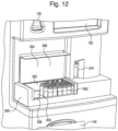
- the automated loading mechanism 200 can be enclosed or encased in a protective housing or casing 260, as shown for example in FIG. 12 .
- the automated loading mechanism 200 or one or more components thereof (i.e., one or more of the loading area, transport means (e.g., conveyor belt 206) and/or entrance location or port (not shown)), can be housed or encased in a protective housing or casing 260.
- the protective housing or casing 260 will have an opening 262 providing access to, and for loading specimen container 500 into/onto the automated loading mechanism 200 housed therein.
- the drum-like loading device 308 is capable of rotating (either in a clock-wise direction, or counter-clock wise direction) about a horizontal axis, and is capable of picking-up and loading individual specimen container 500 into the detection system 100.
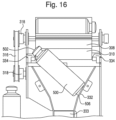
- the rotation of the drum or drum-like loading device 308 picks up a horizontally orientated specimen container 500 in one of a plurality of horizontally orientated slots 310, and moves the container 500, by rotation of the drum or drum-like loading device to a tumbler device 330 (see, e.g., FIG. 16 ).
- Any means in the art can be used for rotation of the drum or drum-like loading device 308.
- the system may employ the use of a motor (not shown) and drive belt 316 for rotation of the drum-like loading device 308.
- the drum or drum-like loading device 308 rotates in a vertical plane (i.e., around or about a horizontal axis) to move the specimen container 500 from the entrance location 306 to a tumbler device 330.
- the tumbler device comprises an open slot at the top of a vertically orientated chute 332.
- the specimen containers are up-righted (i.e., the specimen containers are re-positioned from a horizontal container orientation to an up-right vertical container orientation) by a cam mechanism and vertically orientated chute 332.
- the container 500 will be up-right by the tumbler device 330 regardless of whether the cap end 502 of the container is on the right or left side (see, e.g., FIG. 16 ) of the drum-like loading device 308, as the corresponding ledges 334 will function to hold the cap or top 502 of the container as the bottom 506 falls through the vertical chute 332.
- the vertical cute 332 may further comprise a narrower section 333 that helps direct the falling container 500 into the container locating device 400.
- specimen containers 500 are loaded into, and/or transported within, the detection system 100 using an automated loading mechanism 200 ( FIGS. 1-3 ) or 300 ( FIGS. 13-15 ).
- the containers 500 are typically loaded into the detection system 100 in a vertical orientation (i.e., such that the top or cap portion 502 of the container 500 is up-right).
- the containers 500 are placed or held in a plurality of holding structures or racks 600, and optionally agitated to enhance microorganism growth therein.
- the receiving structures or wells 602 of the holding structures or racks 600 can be orientated in a horizontal axis.
- an automated transfer mechanism (see, e.g., FIG. 5B , 650) must re-orientate the container 500, from a vertical orientation to a horizontal orientation, during the transfer of the container 500 from the automated loading mechanism 200, 300 to the receiving structures or wells 602.
- the transfer mechanism can operate to remove or unload "positive” and “negative” containers from the holding structures or racks 600.
- This automated unloading mechanism can operate to ensure that once a "positive” or “negative” reading has been made for each specimen container 500, the container 500 is removed from the container receiving structures or well 602, making room for another container to be loaded into the detection system 100, thereby increasing system through-put.
- the robotic transfer arm is a 2-, or 3-axis robotic arm and will be capable of transferring the container 500 in one or more horizontal axes (for example, the x- and/or z-axes) and optionally a vertical axis (y-axis) to a specific location, such as the container receiving structures or wells 602 described herein.
- a 2-axis robotic arm will allow movement in 2-axes (for example, the x-, and z-axes)
- a 3-axis robotic arm will allow movement in 3-axes (for example, the x-, y-, and z-axes).
- the 2-, or 3-axis, robotic arm may further employ one or more rotational movements, capable of transferring or moving the specimen container 500 rotationally about one or more axes.
- This rotational movement may allow the robotic transfer arm to transfer a specimen container 500 from a vertical loading orientation to a horizontal orientation.
- the robotic transfer arm may employ a rotational movement to move the specimen container rotationally about or around a horizontal axis.
- This type of robotic transfer arm would be defined as a 3-, or 4- axis robotic arm.
- a robotic arm that allows movement in one horizontal axis (the x-axis), one vertical axis (e.g., the y-axis) and one rotational axis would be considered a 3-axis robotic arm.
- the robotic transfer arm 700 can be a 4-, 5-, or 6-axis robotic arm, thereby allowing movement in the x-, y-, and z-axes, as well as rotational movement about, or around, one-axis (i.e., a 5-axis robot), two axes (i.e., a 5-axis robotic arm), or all three horizontal (x-, and z-axes) and vertical axes (y-axes) (i.e., a 6-axis robotic arm).
- one-axis i.e., a 5-axis robot
- two axes i.e., a 5-axis robotic arm
- y-axes vertical axes
- an upper horizontal support structure (not shown), or other similar means can be used to further support or guide the vertical support structure.
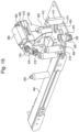
- any means in the art can be used to move the robotic head 710 up and down the vertical support rail 704 (as represented by arrow 726 (see FIG. 18 )), and move the vertical support rail 704 back-and-forth along the horizontal support structure(s) 702B (as represented by arrow 736 (see FIG. 20 )). For example, as shown in FIG.
- the robotic transfer arm 700 may further comprises a vertical drive motor 720 and vertical drive belt 722 that will operate to transfer or move the robotic head 710 up and down (arrow 726) the vertical support rail 704 to transfer or move a container 500 along (i.e., up and down) a vertical axis (i.e., the y-axis).
- the vertical support structure 704 may further comprise a vertical guide rail 728 and a robotic head support block 708, as shown in FIG. 20 . Accordingly, the vertical support structure 704, vertical guide rail 728, vertical drive motor 720 and vertical drive belt 722 allow the robotic transfer arm 700 to move or transfer the robotic head support block 708, and thus, the robotic head 710 and a specimen container 500 along the y-axis.
- the automated transfer mechanism or robotic transfer arm 700 may further comprise a linear or horizontal slide 706 and pivot plate 750.
- the linear or horizontal slide 706 supports the robotic head 710 and gripper mechanism 712.
- the linear or horizontal slide 706 and robotic head 710 may be supported by, coupled to, and/or attached to, a robotic head support block 708 and vertical guide rail 728 (previously described).
- the linear or horizontal slide 706 can be moved up and down (see FIG.
- the pivot slot 754 and pivot slot cam follower 756 rotate the pivot carriage 758 about or around a horizontal axis (i.e., the z-axis), and thus, rotates the robotic head 710 from a horizontal orientation (as shown in FIG. 21A ) to a vertical orientation (as shown in FIG. 21B ), or vice versa.
- the transfer of a container 500 from a vertical entry orientation to a horizontal orientation may be necessary for depositing or placing the container in a horizontally orientated receiving structure or well 602 of the holding structure or rack 600.
- the robotic transfer arm 700 may further comprise a gripping mechanism 712 to pick-up, grip or otherwise hold a specimen container 500.
- the gripping mechanism may comprise two or more gripping fingers 714.
- the gripping mechanism 712 may further comprise a linear actuator 716 and a linear actuator motor 718 which can operate to move the linear actuator to open and close the gripper fingers 714.
- the actuator motor 718 can be used to move the linear actuator 716 of the gripper mechanism 712 thereby moving the gripper fingers 714.
- the linear actuator can be moved in a first direction (e.g., toward the motor) to close the fingers and grip the container 500.
- the linear actuator can be moved in a second direction (e.g., away from the motor) to open the gripper fingers and release the container 500.
- a second direction e.g., away from the motor
- the gripping mechanism 712 allows the gripping mechanism 712 to accommodate (i.e., pick-up and/or hold) a large variety of different specimen containers 500.
- the gripper fingers 714 that extend from about one-quarter (1/4) to about one-half (1/2) the length of the specimen container 500, the gripper fingers will accommodate (i.e., pick-up and/or hold) a number of well known containers (e.g., long neck blood culture bottles) in the art.
- the automated transfer mechanism or robotic transfer arm 700 can be placed under the control of a system controller (not shown) and programmed for specimen container 500 management (e.g., pick-up, transfer, placement and/or container removal) within the detection system 100.
- specimen container 500 management e.g., pick-up, transfer, placement and/or container removal
- the transfer mechanism 700 can be used for automated unloading of "positive” and "negative” specimen containers 500.
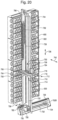
- the holding means or structure of the detection system 100 can take a variety of physical configurations for handling a plurality of individual specimen containers 500 so that a large number of containers (e.g., 200 or 400 containers, depending on the specific holding structures used) can be processed simultaneously.
- the holding means or structure can be used for storage, agitation and/or incubation of the specimen containers 500.
- FIGS. 5A-5B One possible configuration is shown in FIGS. 5A-5B
- FIGS. 9A and 9B are provided by way of illustration and not limitation. As one of skill in the art will appreciate, other designs are possible and contemplated.
- one possible configuration uses a plurality of vertically stacked container holding structures or racks 600 each having a multitude of specimen container receiving structures or wells 602 each for holding individual specimen containers 500.
- two or more vertically stacked holding structures or racks 600 can be used.
- from about 2 to about 40, from about 2 to about 30, from about 2 to about 20, or from about 2 to about 15 vertically stacked holding structures or racks can be used. Referring to FIGS.
- the detection system 100 includes a climate controlled interior chamber 620, comprising an upper interior chamber 622 and a lower interior chamber 624, and a plurality of vertically disposed holding structures or racks 600 (e.g., as shown in FIGS. 5A-5B , 15 vertically stacked holding structures or racks 600) each having a plurality of individual container receiving structures or wells 602 therein.
- Each individual holding structure or rack 600 can comprise two or more container receiving structures of wells 602.
- each holding structure or rack 600 can comprise from about 2 to about 40, from about 2 to about 30, or from about 2 to about 20 receiving structures of wells 602 therein.
- the receiving structures or wells 602 can comprise 2 rows of vertically aligned receiving structures or wells 602.
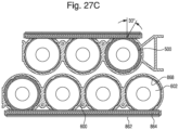
- the receiving structures or wells 602 can be staggered, thus reducing the vertical height of each individual holding structure or rack 600 (see, e.g., FIG. 20 ), and thereby allowing for an increased number of total holding structures or racks 600 in a given vertical distance within the incubation chamber 620.
- the detection system comprises 15 holding structures or racks 600 each comprising two rows of 10 individual container receiving structures or wells 602, thereby giving the system exemplified in FIGS. 5A-5B a total container capacity of 300.
- the detection apparatus may comprise 16 vertically stacked racks, each containing 25 receiving structures or wells, thereby giving a total container capacity of 400.
- each of the individual container receiving structures or wells 602 has a specific X and Y coordinate position or address, where X is the horizontal location and Y is the vertical location of each container receiving structure or well 602.
- the individual wells 602 are accessed by a transfer mechanism, such as a robotic transfer arm, for example, as described hereinabove in conjunction with FIGS. 17-21 ).
- the automated transfer mechanism 700 can operate to move the robotic head 710, and thus, the specimen container 500, to a specific of the X, Y positions in the rack 600 and deposit the container 500 therein.
- the automated transfer mechanism 700 can operate to pick-up a specimen container 500 at the entrance station 110 or the pick-up station 418 of the container locator device 400, move a container 500 determined positive for microbial growth therein to a positive container or exit location 130, and/or to move a container 500 determined negative for microbial growth to a negative container location or waste bin 146.
- the entire holding structure or rack 600 can be agitated by an agitation assembly (not shown) to promote or enhance microorganism growth.
- the agitation assembly can be any known means or mechanism for providing agitation (e.g., a back-and-forth rocking motion) to the holding structures or racks 600.
- the holding structures or racks 600 can be rocked in a back-and-forth motion for agitation of the fluid contained within the containers.
- the holding structures or racks 600 can be rocked back-and-forth from a substantially vertical position to a substantially horizontal position, and repeated to provide agitation of the fluid contained within the container.
- the holding structures or racks 600 can be rocked back-and-forth from a substantially horizontal position to a vertical position 10 degrees, 15 degrees, 30 degrees, 45 degrees or 60 degrees from horizontal, and repeated to provide fluid agitation within the containers.
- a racking motion from a substantially horizontal position to a vertical position from about 10 degrees to about 15 degrees from horizontal may be preferred.
- the holding structure or racks 600 can be rocked back-and-forth in a linear or horizontal motion to provide agitation of the fluid contained within the containers.
- the holding structures or racks 600 and receiving structures or wells 602 can be orientated in a vertical, or alternatively in a horizontal position.
- a linear or horizontal agitation motion with the holding structures 600, and thus the receiving structures or wells 602 and specimen containers 500, in a horizontal orientation can provide substantial agitation with a relatively minimum energy input. Accordingly, in some embodiments, a horizontal holding structure or rack 600 orientation and a linear or horizontal agitation motion, may be preferred. Other means of agitating the holding structures or racks 600, and thus, the fluid within specimen containers 500 are contemplated and would be well understood by one skilled in the art. These back-and-forth, liner and/or horizontal rocking motions can be repeated as desired (e.g., at various cycles and/or speeds) to provide agitation of the fluid within the containers.
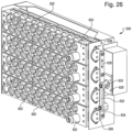
- the agitation assembly 626 comprises one or more holding structures 600 comprising a plurality of holding wells 602 for holding a plurality of specimen containers 500.
- the agitation assembly 626 further comprises an agitation motor 628, an eccentric coupling 630, a first rotation arm 632, a second rotation arm or linkage arm 634 and a rack agitation bearing assembly 636.
- the agitation motor 628 rotates the eccentric coupling 630 in an off-center motion thereby moving a first rotation arm 632 in an off-center circular or off-center rotational motion.
- the off-center rotational movement of the first rotation arm 632 moves a second rotation arm or linkage arm 634 in a linear motion (as represented by arrow 635).
- the linear motion of the second rotation arm or linkage arm 634 rocks the rack agitation bearing assembly 636 in a back-and-forth rocking motion, thereby providing a back-and-forth rocking agitation motion (represented by arrow 638 of FIG. 26 ) to the holding structures 600.
- the detection system 100 may includes upper and lower holding structures 800A and 800B in the form of cylindrical or drum structures containing a multitude of individual specimen container receiving structures or wells 802 for receiving one of the containers 500.
- the cylindrical or drum holding structures 800A, 800B each rotate about a horizontal axis to thereby provide agitation of the containers 500.
- each drum holding structure can comprise from about 8 to about 20 rows (e.g., from about 8 to about 20, from about 8 to about 18, or from about 10 to 1 about 6 rows), each comprising from about 8 to about 20 container receiving structures or wells 802 (e.g., from about 8 to about 20, from about 8 to about 18, or from about 10 to about 16 receiving structures of wells 802).
- rows e.g., from about 8 to about 20, from about 8 to about 18, or from about 10 to about 16 receiving structures of wells 802).
- an automated transfer mechanism 820 is incorporated into the detection system 100 of FIGS. 9A-9B in order to grasp or pick-up a container 500 from the entrance location or port 110, and move or transfer the container 500 to a give receiving structure or well 802, of either the upper or lower drum holding structure 800, and deposit the container 500 therein.
- the automated transfer mechanism 820 in this embodiment can further operate to move a negative container 500 to a waste bin 146, or can operate to move a positive container to the positive container location 130, shown for example, in FIG. 1 .
- the fence is resilient because it is supported on one or more springs that may be expanded or compressed to bias the fence in a direction towards the center of the imaging work-station.
- the fence is made of resilient material, such as foam or rubber, that compresses and then expands to bias the fence in the direction towards the center of the imaging work-station.
- the specimen container may be rotated at a speed that is dependent upon the capabilities of the imaging device to capture images of the specimen container.
- the illumination, exposure of the imaging device, and size of the specimen container can be determined and the system can alter the rate of rotation accordingly, e.g., the rate of rotation can be slowed down when the illumination is determined to be less.
- the method includes imaging the specimen container during the rotation.
- the specimen container is imaged with one or more video or still cameras, sensors, scanners, and/or bar code readers.
- the video camera, sensor, scanner and/or bar code reader may aid in container location, reading of container labels (e.g., bar codes), container scanning, remote field servicing of the system, and/or detecting for any possible container leaks within the system.
- the imaging work-station includes a well into which the specimen container is placed.
- the well is defined by the concave wall or walls that surround at least a portion of the specimen container.
- the well serves as a backdrop to the specimen container when the imaging device is imaging the specimen container.
- the well comprises a surface configured to enhance contrast with the fluid in the specimen container.
- the surface of the well may have a matte finish to reduce reflections.
- the surface of the well may have a color selected to contrast with the fluid in the specimen container, e.g., a white background.
- the method includes illuminating the specimen bottle with a light bar during imaging of the specimen container.
- the light bar produces colored light that is designed to contrast with the fluid in the specimen container.
- the light bar produces blue light to enhance contrast between a cultured blood sample in the specimen bottle and a background of the locator well.
- the light bar is made of or covered with matte or non-reflective materials / finishes to reduce reflections at the imaging work-station.
- the light bar 940 and imaging device 950 is depicted.
- the light bar is positioned adjacent to the specimen container 500, which is centered in in the imaging work-station.
- the light bar 940 includes light sources 942 positioned along its length.
- the light sources 942 are positioned in a pattern to enhance illumination of the specimen container 500.
- the imaging device 950 in this embodiment, is positioned adjacent to the light bar and images the specimen container 500 at a right angle from the vertical axis of the specimen container 500.
- the dimensions and arrangement provided in FIG. 34 are for example purposes and it should be understood that both may change to account for specimen container size, light bar output, ambient light, etc.
- the imaging device is a digital camera.
- the imaging device may be a video camera or similar imaging device.
- the method includes performing dynamic exposure of the imaging device to compensate for different illumination board output levels from the light bar during imaging.
- the system controller controls the dynamic exposure of the imaging device to compensate for different illumination board output levels at time of installation and/or over the lifetime of the illumination board (LED lifetime degradation).
- the dynamic exposure is performed for every image or every specimen container. In other embodiments, the dynamic exposure is performed intermittently, upon user-request, or at pre-determined intervals.
- the system controller performs automatic exposure compensation to adjust image contrast in the presence of ambient illumination variation.
- the goal is to maintain the appropriate contrast for bar code decoding and liquid level processing. This includes keeping the image bright enough without oversaturating the image.
- the exposure compensation is performed such that the maximum exposure does not exceed the value at which motion effects degrade bar code performance. In some embodiments, this value is determined to be 80 (actual exposure register value). In one embodiment, exposure compensation is performed at calibration and periodically during normal bottle processing.
- the method includes positioning the light bar at an angle relative to the vertical axis to optimize the illumination for the detection of foam.
- an exemplary angle is about 18° from horizontal.
- the angle of the light bar permits the light to enter the specimen container so that fluid and any potential foam is illuminated, as well as light the exterior of the specimen container so that the bar code may be read and the fill level determined.
- the angle also reduces reflections on the specimen container because the light is oblique to the imaging device.
- the method includes analyzing an image of the specimen container captured during the rotation.
- an image taken at a single point during the specimen container's rotation is analyzed.
- every image taken of the specimen container during the rotation e.g., 60 images, is analyzed.
- each image is analyzed to determine whether it is a shot of the specimen container that provides a certain type of information, such as fill level, foam presence, identification information, or the like.
- one or more images are aggregated together and a composite image is analyzed.
- the method determines that an indicator, such as a bar code, is present on a specific image and determines, based on the indicator, that this image is to be used for identifying patient information, detecting foam, and/or determining fill level.
- analyzing the image includes decoding one or more codes, e.g., bar codes, on the specimen container.
- decoding a code includes identifying a symbol printed on the side of the specimen container or on a label attached to the side of the specimen container and accessing data relating to the symbol from a database.
- a specimen container may include a bar code that indicates the patient from whom the sample in the specimen container was taken.
- the method may include scanning the bar code and determining the patient associated with the specimen container by accessing a database.
- the label includes one or more codes 924 that can be interpreted by the system controller in association with the imaging device.
- the label includes different codes or indicators associated with different functions. For example, one code may indicate the patient and another code may be used to determine fill level.
- the code may be a 1D or 2D code including, for example, the bottle ID, the lot number, the expiration date, and an authentication code.
- the label is designed in a machine readable format that permits the system controller to gather information on the specimen container when it is imaged.
- the label includes various defined zones which are used for different purposes.
- the label may include a first zone 926 that must be kept clear of user-applied labels in order for the system to correctly detect foam.
- the label includes a second zone 928 defined by a gap that allows the imaging device to image any fluid in the specimen container.
- the label includes a third zone 930 that include a fill-to mark for determining the fill level in the specimen container.
- the fill-to mark is a narrow line within a contrasting block, e.g., a narrow white line in a black block, in order to assist the imaging device in identifying the fill-to mark.
- the label includes a contrasting fourth zone 932, e.g., a white edge, that contrasts with the fluid in the specimen container during foam detection and fill level processes.
- the label includes a zone 934 that permits printed text such as manufacturing date, lot number, and the like.
- the label will include a fill-to label indicator, indicating the level of fluid that should be in the specimen container if correct procedures were followed.
- this fill-to indicator is designed to provide a contrast in the imaging device.
- the fill-to indicator may be a black region surrounded by white on the label.
- the label is designed so that there is a gap in the label on the side of the specimen container.
- the specimen container is transparent and the imaging device is able to detect fluid in the specimen container by imaging the gap.
- This gap may have a range of widths.
- the gap is at least 6.8 mm wide and no more than 8 mm wide. It should be understood that the width of the gap will vary based on the size of the specimen container and the resolution of the imaging device. Wider gaps may cause excessive light and contrast variation.
- a region is positioned adjacent the gap to provide contrast with the image of the gap. For example, a white vertical band may be adjacent to the gap to increase contrast with the dark fluid imaged through the transparent gap.
- the method includes detecting foam in the specimen container based on the analysis of the image.
- the method evaluates the contrast between different portions of a single image in order to detect foam.
- the fluid in the specimen container may be depicted as a first color in the image
- the foam may be depicted as a second color in the image
- the headspace in the specimen container may be depicted as a third color in the image.
- the method may include detecting the presence of foam based on identifying the contrast between the first, second, and third colors.
- foam is detected based on identifying a pattern in the image as well. For example, the edges of bubbles in the foam may create a web-shaped pattern that is discernible in the image.
- detection of foam is binary, e.g., foam is either present or not present; in other embodiments, detection of foam includes determining a volume, height, or amount of foam in the headspace of the specimen container.
- the method when foam is detected the method includes reducing foam in the specimen container before proceeding to determine fill level.
- the specimen container may be loaded into a well in the device and permitted to settle for a period of time before re-testing for the presence of foam.
- the specimen container is agitated while in the well in order to reduce foam.
- the method includes determining the fill level in the specimen container. In one embodiment, the fill level is determined only when the system does not detect foam in the specimen container. In another embodiment, the fill level is determined even if foam has been detected previously if a predetermined time period has elapsed from the foam detection. In further embodiments, a user may override the system and instruct the system to determine the fill level in the specimen container.
- determining the fill level includes comparing the contrast depicted between the fluid level and the header of the specimen container. For example, a specimen container filled with a blood sample and culture medium will appear dark in an image because of the blue light used by the camera. In contrast, the headspace in the specimen container will appear lighter because of the white background of the well in which the specimen container is rotating. This dark fluid level and white headspace can be identified in an image and the fluid level in the container determined.
- the fluid level is determined based on the meniscus of the fluid.
- the fluid level may be the average of the fluid height at the edges of the specimen container and the fluid height at the midpoint of the specimen container. In this way, an average fluid height is determined that accounts for the meniscus effect in the specimen container.
- the fluid height may be determined only from the edges of the specimen container or only from the center of the specimen container.
- determining the fill level includes determining a first distance between a bottom of the specimen container and a marker on a side of the specimen container; determining a second distance between the bottom of the specimen container and a fluid level in the specimen container; and determining a difference between the first distance and the second distance.
- This method controls for instruments that may be installed in a tilted position. For example, the entire instrument may be mounted on a non-level floor. This results in specimen containers, which may be corrected positioned in the imaging work-station, to be at an angle as well. The angle results in the meniscus of the top of the fluid being at an angle, and therefore the fill level determination may be incorrect.
- this method controls for situations where the specimen container is seated at a higher or lower height in the imaging work-station. For example, one specimen container may be depressed in the cup in the imaging work-station and a second specimen container may be raised on the lip of the cup in the imaging work-station. Controlling for the position of the base of the specimen container can resolve issues with improper positioning of the specimen container.
- the method includes stitching a plurality of images captured during the rotation into a single image.
- the system may identify the images based on comparison of features depicted in each image in order to align the images for stitching or merging. For example, in some embodiments the images have overlapping portions that can be matched up to align the images into a single digital image.
- the single image is generated from a video of the specimen container that is recorded as the specimen container is rotated.
- the method includes displaying the single image of the specimen container to a user.
- the stitched image may be displayed on a screen for the user to confirm that the name on the label matches the name identified via the bar code.
- the method includes creating a stitched image that will show the entire label in a single image that allows laser engraved and hand written text on the label to be human readable.
- the label is annotated by the system. For example, if foam is present the foam may be highlighted in the image, or the fill level may be highlighted. In one embodiment, the fill level is highlighted so that a user may compare the determined fill level to the fill level depicted on the single stitched image.
- the inoculation of a specimen container with a test sample, especially a blood sample can lead to foaming within the bottle. Additional foaming can be introduced into the inoculated container by mixing or shaking of the container, by transport of the container to a laboratory, and/or generally by rough handling of the container by a phlebotomist or laboratory technician.
- the total foam contained in the specimen container may comprise a total foam volume of from about 0.1 to about 10 ml, from about 0.5 to about 8 ml, or from about 1 to about 5 ml.
- the liquid level detected may be perceived as a lower liquid level or volume than actually present in the container.
- an inoculated 10 ml test sample may only be perceived as less than 9 ml, less than 8 ml, less than 7 ml, less than 6 ml, or less than 5 ml.
- the presence of this foam within the specimen container is persistent, typically lasting for several hours, and can interfere with accurate determination of the liquid level and/or fluid volume within the container, especially when an imaging system, ultrasonic reflectometry system, or other similar system is used.
- the present invention is directed to a method for dissipating foam for the accurate determination of the fill level within a blood culture bottle using an imaging system.
- This method results in a substantial reduction of the foam in a specimen container in less than 120, 90, 60, 30 or 15 minutes thereby allowing for accurate determination of the liquid fill level and/or fluid volume in the container using an imaging system, or other similar fill level determination means, as described above.
- the foam is "substantially reduced" when the initial foam volume is reduced by more than 50%, more than 60%, more than 70%, more than 80%, or more than 90%.
- the method provides for dissipating or substantially reducing the foam in a specimen container and subsequently determining the liquid fill level in the bottle using an imaging system, ultrasonic reflectometry system, or other similar system, and image processing software.
- the method includes the steps of: inoculating a sealable specimen container (e.g., a BacT/ALERT ® bottle) with a test sample (e.g., a blood sample) the specimen container having an internal chamber with a culture medium disposed therein for culturing any microorganisms that may be present in the test; optionally acquiring an image or measuring the liquid level of said inoculated specimen container using an imaging system, ultrasonic reflectometry system, or other similar system; transferring said inoculated specimen container to a holding structure and agitating the holding structure and inoculated container thereby substantially dissipating any foam that may be present in said specimen container; and subsequently transferring said container to said imaging system, wherein said fill level in said container is determined by first acquiring an image with
Landscapes
- Physics & Mathematics (AREA)
- General Physics & Mathematics (AREA)
- Engineering & Computer Science (AREA)
- Biochemistry (AREA)
- Analytical Chemistry (AREA)
- Chemical & Material Sciences (AREA)
- General Health & Medical Sciences (AREA)
- Life Sciences & Earth Sciences (AREA)
- Immunology (AREA)
- Pathology (AREA)
- Health & Medical Sciences (AREA)
- Theoretical Computer Science (AREA)
- Computer Vision & Pattern Recognition (AREA)
- Quality & Reliability (AREA)
- Signal Processing (AREA)
- Fluid Mechanics (AREA)
- Apparatus Associated With Microorganisms And Enzymes (AREA)
- Automatic Analysis And Handling Materials Therefor (AREA)
- Measuring Or Testing Involving Enzymes Or Micro-Organisms (AREA)
- Investigating Or Analyzing Non-Biological Materials By The Use Of Chemical Means (AREA)
Claims (13)
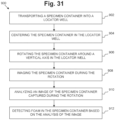
- Ein Verfahren zum Erkennen von Schaum (900) in einem Probenbehälter (500), wobei das Verfahren Folgendes beinhaltet:Transportieren (902) eines Probenbehälters in eine Lokatoraufnahme (402) einer Behälterlokatoreinrichtung (400);Rotieren der Behälterlokatoreinrichtung (400) zu einer Bilderfassungsarbeitsstation (914), wo der Probenbehälter bildlich erfasst werden kann;Zentrieren (904) des Probenbehälters in der Lokatoraufnahme, wobei das Zentrieren das Bereitstellen einer Begrenzung (920) benachbart zu dem Probenbehälter an der Bilderfassungsarbeitsstation beinhaltet, wobei die Begrenzung so positioniert ist, dass sie den Probenbehälter in Ausrichtung mit einer vertikalen Mittellinie einer Rotationsachse drückt, wenn der Probenbehälter sich aus der Ausrichtung mit der vertikalen Mittellinie der Rotationsachse bewegt, wobei optional die Begrenzung elastisch ist, sodass die Begrenzung, wenn der Probenbehälter gegen die Begrenzung drückt, zurückfedert, um den Probenbehälter in Richtung der Mitte der Bilderfassungsarbeitsstation zurückzudrücken;Rotieren (906) des Probenbehälters um eine vertikale Achse in der Lokatoraufnahme;bildliches Erfassen (908) einer Reihe überlappender Bilder, die einen Umfang des Probenbehälters abdecken, während der Rotation, Beleuchten des Probenbehälters mit blauem Licht von einem Lichtbalken (940) während des bildlichen Erfassens des Probenbehälters, um den Kontrast zwischen einem Fluid in dem Probenbehälter und einem Hintergrund der Lokatoraufnahme zu verstärken, wobei der Lichtbalken in einem Winkel relativ zu der vertikalen Achse positioniert ist, um die Beleuchtung für die Erkennung von Schaum zu optimieren;Analysieren (910) der Reihe überlappender Bilder des Probenbehälters, die während der Rotation erfasst wurden; undErkennen (912) von Schaum in dem Probenbehälter, basierend auf der Analyse der Reihe überlappender Bilder;wobei das Analysieren und Erkennen durch Verwendung eines Servers ausgeführt wird, der einen Prozessor und Speicher beinhaltet, wobei der Speicher computerlesbaren Programmcode aufweist und der Prozessor zum bildlichen Erfassen, Analysieren und Erkennen programmiert ist.
- Verfahren gemäß Anspruch 1, das ferner Folgendes beinhaltet:Zusammenfügen einer Vielzahl von während der Rotation erfassten Bildern zu einem Einzelbild undDarstellen des Einzelbildes des Probenbehälters für einen Benutzer.
- Verfahren gemäß Anspruch 1 oder Anspruch 2, das ferner das Rotieren des Probenbehälters mit einer nominellen Rotationsdauer von ungefähr 1,8 Sek./Rotation beinhaltet.
- Verfahren gemäß einem der Ansprüche 1 bis 3, das ferner Folgendes beinhaltet:Bestimmen eines ersten Abstands zwischen einem Boden des Probenbehälters und einer Markierung auf einer Seite des Probenbehälters;Bestimmen eines zweiten Abstands zwischen dem Boden des Probenbehälters und einem Flüssigkeitsniveau in dem Probenbehälter; undBestimmen einer Differenz zwischen dem ersten Abstand und dem zweiten Abstand.
- Verfahren gemäß einem der Ansprüche 1 bis 4, wobei das Zentrieren das Transportieren des Probenbehälters in einen Napf (916) in der Mitte der Lokatoraufnahme und das Positionieren des Probenbehälters innerhalb von 1 mm von einer vertikalen Mittellinie der Rotationsachse beinhaltet.
- Verfahren gemäß einem der Ansprüche 1 bis 5, das ferner das Durchführen dynamischer Exposition einer Bilderfassungseinrichtung gegenüber dem Lichtbalken beinhaltet, um unterschiedliche Ausgabeniveaus der Beleuchtungsleiste während der Bilderfassung auszugleichen.
- Eine Vorrichtung zum Erkennen von Schaum in einem Probenbehälter (500); wobei die Vorrichtung Folgendes beinhaltet:einen automatisierten Lademechanismus (200) zum Transportieren eines Probenbehälters (500), der ein Fluid enthält, in eine Lokatoraufnahme (402);eine Behälterlokatoreinrichtung (400), die eine rotierbare Scheibe beinhaltet, die eine oder mehrere Lokatoraufnahmen enthält, wobei jede Lokatoraufnahme in der Lage ist, einen einzigen Probenbehälter (500) zu halten, wobei die rotierbare Scheibe in einer horizontalen Ebene um eine vertikale Achse rotierbar ist, um den Probenbehälter zu einer oder mehreren Behälterarbeitsablaufstationen zu bewegen;einen rotierbaren Drehteller (406) an einer Bilderfassungsstation (914) von einer der Behälterarbeitsablaufstationen (404), wobei der rotierbare Drehteller dazu konfiguriert ist, den Probenbehälter in einer horizontalen Ebene um eine vertikale Achse in der Lokatoraufnahme zu rotieren;wobei die Vorrichtung ferner Folgendes beinhaltet:mindestens eine Zentriereinrichtung (916), die dazu konfiguriert ist, den Probenbehälter in der Lokatoraufnahme an der Bilderfassungsstation (914) zu zentrieren, wobei die Zentriereinrichtung eine Begrenzung (920) benachbart zu dem Probenbehälter an der Bilderfassungsarbeitsstation (914) beinhaltet, wobei die Begrenzung so positioniert ist, dass sie den Probenbehälter in Ausrichtung mit einer vertikalen Mittellinie einer Rotationsachse drückt, wenn der Probenbehälter sich aus der Ausrichtung mit der vertikalen Mittellinie der Rotationsachse bewegt, wobei optional die Begrenzung elastisch ist, sodass die Begrenzung, wenn der Probenbehälter gegen die Begrenzung drückt, zurückfedert, um den Probenbehälter in Richtung der Mitte der Bilderfassungsarbeitsstation zurückzudrücken;einen blauen Lichtbalken (940), der positioniert ist, um den Probenbehälter während der bildlichen Erfassung des Probenbehälters zu beleuchten, um den Kontrast zwischen dem Fluid in dem Probenbehälter und einem Hintergrund der Lokatoraufnahme zu verstärken, wobei der blaue Lichtbalken in einem Winkel relativ zu der vertikalen Achse positioniert ist, um die Beleuchtung zur Erkennung von Schaum zu optimieren;eine Bilderfassungseinrichtung (950), die nahe der Bilderfassungsstation (914) positioniert ist; undeinen Server, der einen Prozessor und Speicher beinhaltet, wobei der Speicher computerlesbaren Programmcode aufweist und der Prozessor zu Folgendem programmiert ist:bildliches Erfassen einer Reihe überlappender Bilder, die einen Umfang des Probenbehälters abdecken, während der Rotation,Analysieren der Reihe überlappender Bilder des Probenbehälters, die während der Rotation erfasst wurden; undErkennen von Schaum in dem Probenbehälter, basierend auf der Analyse der Reihe überlappender Bilder.
- Vorrichtung gemäß Anspruch 7, wobei die Zentriereinrichtung (916) ferner einen Napf beinhaltet, der in einer Mitte der Lokatoraufnahme an der Bilderfassungsstation positioniert ist.
- Vorrichtung gemäß Anspruch 7 oder Anspruch 8, die ferner einen Motor beinhaltet, der dazu konfiguriert ist, den Probenbehälter mit einer nominellen Rotationsdauer von ungefähr 1,8 Sek./Rotation zu rotieren.
- Vorrichtung gemäß einem der Ansprüche 7 bis 9, wobei der Prozessor ferner dazu programmiert ist, dynamische Exposition der Bilderfassungseinrichtung gegenüber dem Lichtbalken durchzuführen, um unterschiedliche Ausgabeniveaus der Beleuchtungsleiste während der Bilderfassung auszugleichen.
- Vorrichtung gemäß einem der Ansprüche 7 bis 10, wobei die Aufnahme eine Oberfläche beinhaltet, die dazu konfiguriert ist, Kontrast mit dem Fluid in dem Probenbehälter zu verstärken.
- Vorrichtung gemäß einem der Ansprüche 7 bis 11, wobei der Prozessor ferner zu Folgendem programmiert ist:Zusammenfügen einer Vielzahl von während der Rotation erfassten Bildern zu einem Einzelbild undDarstellen des Einzelbildes des Probenbehälters für einen Benutzer.
- Vorrichtung gemäß einem der Ansprüche 7 bis 12, wobei der Prozessor ferner zu Folgendem programmiert ist:Bestimmen eines ersten Abstands zwischen einem Boden des Probenbehälters und einer Markierung auf einer Seite des Probenbehälters;Bestimmen eines zweiten Abstands zwischen dem Boden des Probenbehälters und einem Flüssigkeitsniveau in dem Probenbehälter; undBestimmen einer Differenz zwischen dem ersten Abstand und dem zweiten Abstand.
Priority Applications (1)
| Application Number | Priority Date | Filing Date | Title |
|---|---|---|---|
| EP25176481.7A EP4579592A3 (de) | 2016-05-27 | 2017-05-26 | Verfahren und vorrichtung zur detektion von schaum in probenbehältern |
Applications Claiming Priority (2)
| Application Number | Priority Date | Filing Date | Title |
|---|---|---|---|
| US201662342502P | 2016-05-27 | 2016-05-27 | |
| PCT/US2017/034741 WO2017205778A1 (en) | 2016-05-27 | 2017-05-26 | Method and apparatus for detection of foam in specimen containers |
Related Child Applications (2)
| Application Number | Title | Priority Date | Filing Date |
|---|---|---|---|
| EP25176481.7A Division EP4579592A3 (de) | 2016-05-27 | 2017-05-26 | Verfahren und vorrichtung zur detektion von schaum in probenbehältern |
| EP25176481.7A Division-Into EP4579592A3 (de) | 2016-05-27 | 2017-05-26 | Verfahren und vorrichtung zur detektion von schaum in probenbehältern |
Publications (3)
| Publication Number | Publication Date |
|---|---|
| EP3465612A1 EP3465612A1 (de) | 2019-04-10 |
| EP3465612A4 EP3465612A4 (de) | 2020-02-26 |
| EP3465612B1 true EP3465612B1 (de) | 2025-07-02 |
Family
ID=60411543
Family Applications (2)
| Application Number | Title | Priority Date | Filing Date |
|---|---|---|---|
| EP17803689.3A Active EP3465612B1 (de) | 2016-05-27 | 2017-05-26 | Verfahren und vorrichtung zur erkennung von schaum in probenbehältern |
| EP25176481.7A Pending EP4579592A3 (de) | 2016-05-27 | 2017-05-26 | Verfahren und vorrichtung zur detektion von schaum in probenbehältern |
Family Applications After (1)
| Application Number | Title | Priority Date | Filing Date |
|---|---|---|---|
| EP25176481.7A Pending EP4579592A3 (de) | 2016-05-27 | 2017-05-26 | Verfahren und vorrichtung zur detektion von schaum in probenbehältern |
Country Status (8)
| Country | Link |
|---|---|
| US (2) | US10395357B2 (de) |
| EP (2) | EP3465612B1 (de) |
| JP (2) | JP6937325B2 (de) |
| CN (1) | CN109564681A (de) |
| AU (2) | AU2017269412B2 (de) |
| CA (1) | CA3025641A1 (de) |
| ES (1) | ES3037008T3 (de) |
| WO (1) | WO2017205778A1 (de) |
Families Citing this family (22)
| Publication number | Priority date | Publication date | Assignee | Title |
|---|---|---|---|---|
| WO2017205778A1 (en) * | 2016-05-27 | 2017-11-30 | Biomerieux, Inc. | Method and apparatus for detection of foam in specimen containers |
| DE102016114190A1 (de) * | 2016-08-01 | 2018-02-01 | Schott Schweiz Ag | Verfahren und Vorrichtung zur optischen Untersuchung transparenter Körper |
| JP6800223B2 (ja) | 2016-10-28 | 2020-12-16 | ベックマン コールター, インコーポレイテッド | 物質調製評価システム |
| EP3594638A1 (de) * | 2018-07-13 | 2020-01-15 | Tecan Trading Ag | Vorrichtungen und verfahren zur kapazitiven schaumdetektion in flüssigkeitsbehältern |
| IL279322B2 (en) * | 2018-07-31 | 2025-11-01 | Amgen Inc | A robotic system for inspecting pharmaceutical containers based on pattern recognition |
| US11406981B2 (en) | 2018-08-22 | 2022-08-09 | Biomerieux, Inc. | Detection instruments with automated cell location selection for newly intaken specimen containers and related methods |
| EP3620984B1 (de) | 2018-09-06 | 2024-04-10 | Accenture Global Solutions Limited | Digitale qualitätskontrolle mit computervisionierung und deep learning |
| US20230048936A1 (en) * | 2018-11-22 | 2023-02-16 | Kaya17 Inc. | System and method for detecting presence of a target bioparticle in a sample via a vertical flow assay |
| TWI695968B (zh) * | 2019-08-12 | 2020-06-11 | 建國科技大學 | 具自動偵測容器高度與容量的自動注入裝置 |
| CN110389131A (zh) * | 2019-08-21 | 2019-10-29 | 汕头市结核病防治所(汕头市呼吸系疾病防治所) | 一种痰液合格验视装置 |
| CN114586106A (zh) | 2019-11-05 | 2022-06-03 | 美国西门子医学诊断股份有限公司 | 分析样本的系统、装置和方法 |
| CN111103238A (zh) * | 2020-01-21 | 2020-05-05 | 深圳橙子自动化有限公司 | 一种检测装置 |
| GB2592590B (en) * | 2020-03-02 | 2024-02-14 | Agilent Technologies Inc | Sample processing with information detection during transfer of a sample container |
| JP7436270B2 (ja) | 2020-04-09 | 2024-02-21 | 株式会社日立ハイテク | 生体検体解析装置 |
| EP4139692A1 (de) * | 2020-04-24 | 2023-03-01 | Gen-Probe Incorporated | System und verfahren zur differentiellen messung eines flüssigkeitsstands in einem probenbehälter |
| EP3922205A1 (de) * | 2020-06-12 | 2021-12-15 | Gibotech A/S | System zum anordnen von behältern und behälterdeckeln auf einem gestell in einer sterilen verarbeitungsabteiliung |
| US20220145228A1 (en) * | 2020-11-10 | 2022-05-12 | GlassWRX, LLC | Method for high durability engineered cellular magmatic microbial habitat and articles thereof |
| CN116964456A (zh) * | 2021-03-10 | 2023-10-27 | Bd科斯特公司 | 用于对容器进行成像的系统和方法 |
| CA3214213A1 (en) * | 2021-03-31 | 2022-10-06 | Michael Allen MOTYKA | Laser marked calibration standards for on-line inspection camera qualification and methods of use |
| US12170849B2 (en) * | 2022-02-04 | 2024-12-17 | Applied Materials, Inc. | Pulsed illumination for fluid inspection |
| NL2032976B1 (en) * | 2022-09-07 | 2024-03-21 | Luo Automation B V | Container inspection device |
| TW202436190A (zh) * | 2022-12-30 | 2024-09-16 | 加拿大商辛波提克加拿大公司 | 裝箱貨物檢驗及其方法 |
Family Cites Families (56)
| Publication number | Priority date | Publication date | Assignee | Title |
|---|---|---|---|---|
| US5164796A (en) | 1988-03-15 | 1992-11-17 | Akzo N.V. | Apparatus and method for detection of microorganisms |
| US5518895A (en) | 1990-02-15 | 1996-05-21 | Akzo N.V. | Device for detecting microorganisms using piezoelectric means |
| US5094955A (en) | 1988-03-15 | 1992-03-10 | Akzo N.V. | Device and method for detecting microorganisms |
| US5162229A (en) | 1988-03-15 | 1992-11-10 | Akzo N.V. | Device and method for enhanced recovery and detection of microbial growth in the presence of antimicrobial substances |
| US4945060A (en) | 1988-03-15 | 1990-07-31 | Akzo N. V. | Device for detecting microorganisms |
| US5217876A (en) | 1988-03-15 | 1993-06-08 | Akzo N.V. | Method for detecting microorganisms |
| US5542004A (en) * | 1991-11-25 | 1996-07-30 | Miller Brewing Company | Foam analyzing method and apparatus |
| US5432061A (en) | 1992-09-01 | 1995-07-11 | Becton Dickinson And Company | Method and apparatus for detecting microorganisms |
| US5344417A (en) | 1992-09-11 | 1994-09-06 | Becton, Dickinson And Company | Universal fitting for inoculation receptacles |
| US5371016A (en) | 1993-04-26 | 1994-12-06 | Becton, Dickinson And Company | Detecting biological activities in culture vials |
| US5397709A (en) | 1993-08-27 | 1995-03-14 | Becton Dickinson And Company | System for detecting bacterial growth in a plurality of culture vials |
| US5536935A (en) * | 1994-02-17 | 1996-07-16 | Thermedics Detection, Inc. | Detection of foaming contaminants in containers using image processing |
| US5498543A (en) | 1994-06-07 | 1996-03-12 | Becton Dickinson And Company | Sub-compact blood culture apparatus |
| JP4066200B2 (ja) | 1995-06-05 | 2008-03-26 | アクゾ・ノベル・エヌ・ベー | 微生物を検出するデバイスおよび方法 |
| US5518923A (en) | 1995-06-06 | 1996-05-21 | Becton Dickinson And Company | Compact blood culture apparatus |
| US5770394A (en) | 1996-05-22 | 1998-06-23 | Becton Dickinson And Company | Method and apparatus for detecting bacteria using a blood culture froth |
| US6467362B2 (en) | 1997-04-17 | 2002-10-22 | Kerk Motion Products, Inc. | Reinforced lead screw with spring biased anti-backlash nut |
| DE19919305A1 (de) * | 1999-04-28 | 2000-11-02 | Roche Diagnostics Gmbh | Verfahren und Vorrichtung zum Flüssigkeitstransfer mit einem Analysegerät |
| US6408679B1 (en) * | 2000-02-04 | 2002-06-25 | The United States Of America As Represented By The Administrator Of The National Aeronautics And Space Administration | Bubble measuring instrument and method |
| US6642019B1 (en) * | 2000-11-22 | 2003-11-04 | Synthecan, Inc. | Vessel, preferably spherical or oblate spherical for growing or culturing cells, cellular aggregates, tissues and organoids and methods for using same |
| CA2442282A1 (en) * | 2001-03-29 | 2002-10-10 | Cellect Technologies Corp. | Methods devices and systems for sorting and separating particles |
| GB0112392D0 (en) * | 2001-05-22 | 2001-07-11 | Medical Res Council | Optical imaging appartus and associated specimen support means |
| US6709857B2 (en) | 2001-06-26 | 2004-03-23 | Becton, Dickinson And Company | System and method for optically monitoring the concentration of a gas in a sample vial using photothermal spectroscopy to detect sample growth |
| US7211430B2 (en) | 2001-08-03 | 2007-05-01 | Becton, Dickinson And Company | System for stirring growth medium |
| WO2004077008A2 (en) * | 2003-02-28 | 2004-09-10 | Imperial Chemical Industries Plc | Foam assessment |
| US8195328B2 (en) * | 2003-09-19 | 2012-06-05 | Vesta Medical, Llc | Combination disposal and dispensing apparatus and method |
| JP2005283527A (ja) * | 2004-03-31 | 2005-10-13 | Hitachi High-Technologies Corp | 異物検出装置 |
| JP4500617B2 (ja) * | 2004-07-22 | 2010-07-14 | テルモ株式会社 | 気泡除去装置 |
| EP1630550A1 (de) * | 2004-08-27 | 2006-03-01 | Moller & Devicon A/S | Verfahren und Vorrichtungen zum Nachweis von Fremdkörpern oder Fehlern in einer Menge gefüllter Behälter |
| EP1934585B1 (de) * | 2005-10-15 | 2010-04-28 | Udviklingsselskabet Innoscan K/S | Verfahren und system zur bestrahlung und inspektion flüssigkeitstragender behälter |
| US7876935B2 (en) * | 2006-01-30 | 2011-01-25 | Protedyne Corporation | Sample processing apparatus with a vision system |
| WO2008021990A2 (en) * | 2006-08-10 | 2008-02-21 | Barnes Allen C | Portable biological testing device and method |
| US9002096B2 (en) | 2009-01-06 | 2015-04-07 | Siemens Healthcare Diagnostics Inc. | Method and apparatus for determining a liquid level in a container using imaging |
| WO2010132749A2 (en) * | 2009-05-15 | 2010-11-18 | Biomerieux, Inc. | Automated transfer mechanism for microbial. detection apparatus |
| EP3974838B1 (de) * | 2009-08-13 | 2026-04-22 | Siemens Healthcare Diagnostics Inc. | Verfahren zur ermittlung physikalischer dimensionen in flüssigproben und durch klinische analysegeräte zu analysierenden behältern |
| JP2011092104A (ja) * | 2009-10-30 | 2011-05-12 | Hitachi Engineering & Services Co Ltd | 微生物などの検査方法及び検査装置 |
| US8319823B2 (en) * | 2009-11-03 | 2012-11-27 | Jadak, Llc | System and method for panoramic image stitching |
| US8865630B2 (en) * | 2010-02-26 | 2014-10-21 | Massachusetts Institute Of Technology | High-throughput platform for in-vivo sub-cellular screens on vertebrate larvae |
| DE102010012570B4 (de) * | 2010-03-23 | 2024-08-14 | Krones Aktiengesellschaft | Vorrichtung und Verfahren zum Untersuchen von befüllten Behältnissen auf Fremdkörper |
| US8867803B2 (en) | 2010-04-20 | 2014-10-21 | Eric J. Seibel | Optical projection tomography microscopy (OPTM) for large specimen sizes |
| US20120021452A1 (en) * | 2010-07-22 | 2012-01-26 | Biomerieux, Inc. | Belt Agitation System For Culture Bottles |
| EP2453233A1 (de) | 2010-11-16 | 2012-05-16 | Roche Diagnostics GmbH | Verfahren und Vorrichtung zum Erkennen von Schaum auf einer Flüssigkeitsoberfläche in einem Schiff |
| MX349288B (es) * | 2011-01-21 | 2017-07-21 | Theranos Inc | Sistemas y metodos para maximizacion de uso de muestras. |
| JP2014518394A (ja) * | 2011-06-30 | 2014-07-28 | スリーエム イノベイティブ プロパティズ カンパニー | 微細構造化表面を使用して、サンプル内の目的の検体を検出するためのシステム及び方法 |
| AU2012284097B2 (en) * | 2011-07-18 | 2017-08-03 | President And Fellows Of Harvard College | Engineered microbe-targeting molecules and uses thereof |
| TWI582408B (zh) * | 2011-08-29 | 2017-05-11 | 安美基公司 | 用於非破壞性檢測-流體中未溶解粒子之方法及裝置 |
| US20160069919A1 (en) * | 2011-09-25 | 2016-03-10 | Theranos, Inc. | Systems and methods for multi-analysis |
| JP5879085B2 (ja) * | 2011-10-13 | 2016-03-08 | 株式会社日立ハイテクノロジーズ | 液面状態検出装置、自動分析装置および液面状態検出方法 |
| WO2014099644A1 (en) * | 2012-12-20 | 2014-06-26 | 3M Innovative Properties Company | Method of detecting gas-producing microbial colonies |
| JP2014145621A (ja) * | 2013-01-28 | 2014-08-14 | Hitachi High-Technologies Corp | 自動分析装置 |
| EP3083055A1 (de) * | 2013-12-20 | 2016-10-26 | 3M Innovative Properties Company | Systeme und verfahren zur probenkonzentration und -erkennung mittels flüssigkeitstrennung |
| EP3101428B1 (de) * | 2014-01-27 | 2021-07-07 | Hitachi High-Tech Corporation | Automatische analytische vorrichtung |
| EP3252476B1 (de) * | 2015-01-28 | 2024-10-30 | Hitachi High-Tech Corporation | Flüssige oberflächeninspektionsvorrichtung, automatisierten analysevorrichtung und verarbeitungsvorrichtung |
| US10719691B2 (en) * | 2015-04-21 | 2020-07-21 | Purdue Research Foundation | Culture imaging system |
| JP6976257B2 (ja) * | 2016-01-28 | 2021-12-08 | シーメンス・ヘルスケア・ダイアグノスティックス・インコーポレーテッドSiemens Healthcare Diagnostics Inc. | マルチビューの特徴付けのための方法及び装置 |
| WO2017205778A1 (en) * | 2016-05-27 | 2017-11-30 | Biomerieux, Inc. | Method and apparatus for detection of foam in specimen containers |
-
2017
- 2017-05-26 WO PCT/US2017/034741 patent/WO2017205778A1/en not_active Ceased
- 2017-05-26 CA CA3025641A patent/CA3025641A1/en active Pending
- 2017-05-26 EP EP17803689.3A patent/EP3465612B1/de active Active
- 2017-05-26 JP JP2018560626A patent/JP6937325B2/ja active Active
- 2017-05-26 EP EP25176481.7A patent/EP4579592A3/de active Pending
- 2017-05-26 CN CN201780046616.4A patent/CN109564681A/zh active Pending
- 2017-05-26 ES ES17803689T patent/ES3037008T3/es active Active
- 2017-05-26 US US15/606,157 patent/US10395357B2/en active Active
- 2017-05-26 AU AU2017269412A patent/AU2017269412B2/en active Active
-
2019
- 2019-08-23 US US16/549,360 patent/US11334980B2/en active Active
-
2021
- 2021-08-30 JP JP2021139665A patent/JP7389772B2/ja active Active
-
2022
- 2022-04-08 AU AU2022202374A patent/AU2022202374B2/en active Active
Non-Patent Citations (1)
| Title |
|---|
| DARYL MARTIN: "A Practical Guide to Machine Vision Lighting A Practical Guide to Machine Vision Lighting", 1 October 2007 (2007-10-01), pages 1 - 18, XP055286048, Retrieved from the Internet <URL:https://www.advancedillumination.com/wp-content/uploads/> [retrieved on 20160705] * |
Also Published As
| Publication number | Publication date |
|---|---|
| JP6937325B2 (ja) | 2021-09-22 |
| CN109564681A (zh) | 2019-04-02 |
| EP4579592A2 (de) | 2025-07-02 |
| JP7389772B2 (ja) | 2023-11-30 |
| AU2017269412B2 (en) | 2022-01-20 |
| US11334980B2 (en) | 2022-05-17 |
| US10395357B2 (en) | 2019-08-27 |
| US20190378265A1 (en) | 2019-12-12 |
| AU2022202374B2 (en) | 2023-11-16 |
| JP2019518449A (ja) | 2019-07-04 |
| WO2017205778A1 (en) | 2017-11-30 |
| AU2022202374A1 (en) | 2022-04-28 |
| AU2017269412A1 (en) | 2018-12-06 |
| ES3037008T3 (en) | 2025-09-26 |
| EP3465612A1 (de) | 2019-04-10 |
| JP2022002510A (ja) | 2022-01-11 |
| EP4579592A3 (de) | 2025-08-06 |
| US20170345141A1 (en) | 2017-11-30 |
| CA3025641A1 (en) | 2017-11-30 |
| EP3465612A4 (de) | 2020-02-26 |
Similar Documents
| Publication | Publication Date | Title |
|---|---|---|
| AU2022202374B2 (en) | Method and apparatus for detection of foam in specimen containers | |
| US11104931B2 (en) | Automated microbial detection apparatus | |
| US10760042B2 (en) | Automated transfer mechanism for microbial detection apparatus |
Legal Events
| Date | Code | Title | Description |
|---|---|---|---|
| STAA | Information on the status of an ep patent application or granted ep patent |
Free format text: STATUS: THE INTERNATIONAL PUBLICATION HAS BEEN MADE |
|
| PUAI | Public reference made under article 153(3) epc to a published international application that has entered the european phase |
Free format text: ORIGINAL CODE: 0009012 |
|
| STAA | Information on the status of an ep patent application or granted ep patent |
Free format text: STATUS: REQUEST FOR EXAMINATION WAS MADE |
|
| 17P | Request for examination filed |
Effective date: 20181221 |
|
| AK | Designated contracting states |
Kind code of ref document: A1 Designated state(s): AL AT BE BG CH CY CZ DE DK EE ES FI FR GB GR HR HU IE IS IT LI LT LU LV MC MK MT NL NO PL PT RO RS SE SI SK SM TR |
|
| AX | Request for extension of the european patent |
Extension state: BA ME |
|
| DAV | Request for validation of the european patent (deleted) | ||
| DAX | Request for extension of the european patent (deleted) | ||
| A4 | Supplementary search report drawn up and despatched |
Effective date: 20200124 |
|
| RIC1 | Information provided on ipc code assigned before grant |
Ipc: G06T 7/00 20170101AFI20200120BHEP |
|
| STAA | Information on the status of an ep patent application or granted ep patent |
Free format text: STATUS: EXAMINATION IS IN PROGRESS |
|
| 17Q | First examination report despatched |
Effective date: 20201015 |
|
| GRAP | Despatch of communication of intention to grant a patent |
Free format text: ORIGINAL CODE: EPIDOSNIGR1 |
|
| STAA | Information on the status of an ep patent application or granted ep patent |
Free format text: STATUS: GRANT OF PATENT IS INTENDED |
|
| INTG | Intention to grant announced |
Effective date: 20241220 |
|
| GRAS | Grant fee paid |
Free format text: ORIGINAL CODE: EPIDOSNIGR3 |
|
| P01 | Opt-out of the competence of the unified patent court (upc) registered |
Free format text: CASE NUMBER: APP_19347/2025 Effective date: 20250423 |
|
| RAP3 | Party data changed (applicant data changed or rights of an application transferred) |
Owner name: BIOMERIEUX, INC. |
|
| GRAA | (expected) grant |
Free format text: ORIGINAL CODE: 0009210 |
|
| STAA | Information on the status of an ep patent application or granted ep patent |
Free format text: STATUS: THE PATENT HAS BEEN GRANTED |
|
| AK | Designated contracting states |
Kind code of ref document: B1 Designated state(s): AL AT BE BG CH CY CZ DE DK EE ES FI FR GB GR HR HU IE IS IT LI LT LU LV MC MK MT NL NO PL PT RO RS SE SI SK SM TR |
|
| REG | Reference to a national code |
Ref country code: GB Ref legal event code: FG4D |
|
| REG | Reference to a national code |
Ref country code: CH Ref legal event code: EP |
|
| REG | Reference to a national code |
Ref country code: DE Ref legal event code: R096 Ref document number: 602017090324 Country of ref document: DE |
|
| REG | Reference to a national code |
Ref country code: IE Ref legal event code: FG4D |
|
| REG | Reference to a national code |
Ref country code: ES Ref legal event code: FG2A Ref document number: 3037008 Country of ref document: ES Kind code of ref document: T3 Effective date: 20250926 |
|
| REG | Reference to a national code |
Ref country code: NL Ref legal event code: MP Effective date: 20250702 |
|
| PG25 | Lapsed in a contracting state [announced via postgrant information from national office to epo] |
Ref country code: PT Free format text: LAPSE BECAUSE OF FAILURE TO SUBMIT A TRANSLATION OF THE DESCRIPTION OR TO PAY THE FEE WITHIN THE PRESCRIBED TIME-LIMIT Effective date: 20251103 |
|
| PG25 | Lapsed in a contracting state [announced via postgrant information from national office to epo] |
Ref country code: NL Free format text: LAPSE BECAUSE OF FAILURE TO SUBMIT A TRANSLATION OF THE DESCRIPTION OR TO PAY THE FEE WITHIN THE PRESCRIBED TIME-LIMIT Effective date: 20250702 |
|
| REG | Reference to a national code |
Ref country code: AT Ref legal event code: MK05 Ref document number: 1810121 Country of ref document: AT Kind code of ref document: T Effective date: 20250702 |
|
| PG25 | Lapsed in a contracting state [announced via postgrant information from national office to epo] |
Ref country code: IS Free format text: LAPSE BECAUSE OF FAILURE TO SUBMIT A TRANSLATION OF THE DESCRIPTION OR TO PAY THE FEE WITHIN THE PRESCRIBED TIME-LIMIT Effective date: 20251102 |
|
| PG25 | Lapsed in a contracting state [announced via postgrant information from national office to epo] |
Ref country code: NO Free format text: LAPSE BECAUSE OF FAILURE TO SUBMIT A TRANSLATION OF THE DESCRIPTION OR TO PAY THE FEE WITHIN THE PRESCRIBED TIME-LIMIT Effective date: 20251002 |
|
| REG | Reference to a national code |
Ref country code: LT Ref legal event code: MG9D |
|
| PG25 | Lapsed in a contracting state [announced via postgrant information from national office to epo] |
Ref country code: AT Free format text: LAPSE BECAUSE OF FAILURE TO SUBMIT A TRANSLATION OF THE DESCRIPTION OR TO PAY THE FEE WITHIN THE PRESCRIBED TIME-LIMIT Effective date: 20250702 |
|
| PG25 | Lapsed in a contracting state [announced via postgrant information from national office to epo] |
Ref country code: FI Free format text: LAPSE BECAUSE OF FAILURE TO SUBMIT A TRANSLATION OF THE DESCRIPTION OR TO PAY THE FEE WITHIN THE PRESCRIBED TIME-LIMIT Effective date: 20250702 |
|
| PG25 | Lapsed in a contracting state [announced via postgrant information from national office to epo] |
Ref country code: HR Free format text: LAPSE BECAUSE OF FAILURE TO SUBMIT A TRANSLATION OF THE DESCRIPTION OR TO PAY THE FEE WITHIN THE PRESCRIBED TIME-LIMIT Effective date: 20250702 |
|
| PG25 | Lapsed in a contracting state [announced via postgrant information from national office to epo] |
Ref country code: GR Free format text: LAPSE BECAUSE OF FAILURE TO SUBMIT A TRANSLATION OF THE DESCRIPTION OR TO PAY THE FEE WITHIN THE PRESCRIBED TIME-LIMIT Effective date: 20251003 |
|
| PG25 | Lapsed in a contracting state [announced via postgrant information from national office to epo] |
Ref country code: CZ Free format text: LAPSE BECAUSE OF FAILURE TO SUBMIT A TRANSLATION OF THE DESCRIPTION OR TO PAY THE FEE WITHIN THE PRESCRIBED TIME-LIMIT Effective date: 20250702 Ref country code: SE Free format text: LAPSE BECAUSE OF FAILURE TO SUBMIT A TRANSLATION OF THE DESCRIPTION OR TO PAY THE FEE WITHIN THE PRESCRIBED TIME-LIMIT Effective date: 20250702 |
|
| PG25 | Lapsed in a contracting state [announced via postgrant information from national office to epo] |
Ref country code: LV Free format text: LAPSE BECAUSE OF FAILURE TO SUBMIT A TRANSLATION OF THE DESCRIPTION OR TO PAY THE FEE WITHIN THE PRESCRIBED TIME-LIMIT Effective date: 20250702 |
|
| PG25 | Lapsed in a contracting state [announced via postgrant information from national office to epo] |
Ref country code: PL Free format text: LAPSE BECAUSE OF FAILURE TO SUBMIT A TRANSLATION OF THE DESCRIPTION OR TO PAY THE FEE WITHIN THE PRESCRIBED TIME-LIMIT Effective date: 20250702 Ref country code: BG Free format text: LAPSE BECAUSE OF FAILURE TO SUBMIT A TRANSLATION OF THE DESCRIPTION OR TO PAY THE FEE WITHIN THE PRESCRIBED TIME-LIMIT Effective date: 20250702 |
|
| PG25 | Lapsed in a contracting state [announced via postgrant information from national office to epo] |
Ref country code: RS Free format text: LAPSE BECAUSE OF FAILURE TO SUBMIT A TRANSLATION OF THE DESCRIPTION OR TO PAY THE FEE WITHIN THE PRESCRIBED TIME-LIMIT Effective date: 20251002 |
|
| PG25 | Lapsed in a contracting state [announced via postgrant information from national office to epo] |
Ref country code: SM Free format text: LAPSE BECAUSE OF FAILURE TO SUBMIT A TRANSLATION OF THE DESCRIPTION OR TO PAY THE FEE WITHIN THE PRESCRIBED TIME-LIMIT Effective date: 20250702 |
|
| PG25 | Lapsed in a contracting state [announced via postgrant information from national office to epo] |
Ref country code: DK Free format text: LAPSE BECAUSE OF FAILURE TO SUBMIT A TRANSLATION OF THE DESCRIPTION OR TO PAY THE FEE WITHIN THE PRESCRIBED TIME-LIMIT Effective date: 20250702 |
|
| PG25 | Lapsed in a contracting state [announced via postgrant information from national office to epo] |
Ref country code: SK Free format text: LAPSE BECAUSE OF FAILURE TO SUBMIT A TRANSLATION OF THE DESCRIPTION OR TO PAY THE FEE WITHIN THE PRESCRIBED TIME-LIMIT Effective date: 20250702 Ref country code: EE Free format text: LAPSE BECAUSE OF FAILURE TO SUBMIT A TRANSLATION OF THE DESCRIPTION OR TO PAY THE FEE WITHIN THE PRESCRIBED TIME-LIMIT Effective date: 20250702 |