EP3464822B1 - Turbine engine with a swirler - Google Patents
Turbine engine with a swirler Download PDFInfo
- Publication number
- EP3464822B1 EP3464822B1 EP17822062.0A EP17822062A EP3464822B1 EP 3464822 B1 EP3464822 B1 EP 3464822B1 EP 17822062 A EP17822062 A EP 17822062A EP 3464822 B1 EP3464822 B1 EP 3464822B1
- Authority
- EP
- European Patent Office
- Prior art keywords
- swirler
- turbine
- engine
- airflow
- turbine engine
- Prior art date
- Legal status (The legal status is an assumption and is not a legal conclusion. Google has not performed a legal analysis and makes no representation as to the accuracy of the status listed.)
- Active
Links
- 239000012530 fluid Substances 0.000 claims description 22
- 238000000034 method Methods 0.000 claims description 8
- 230000003068 static effect Effects 0.000 claims description 8
- 238000004891 communication Methods 0.000 claims description 5
- 230000001939 inductive effect Effects 0.000 claims description 2
- 239000003570 air Substances 0.000 description 16
- 239000007789 gas Substances 0.000 description 13
- 238000002485 combustion reaction Methods 0.000 description 7
- 238000001816 cooling Methods 0.000 description 6
- 238000011144 upstream manufacturing Methods 0.000 description 4
- 239000012080 ambient air Substances 0.000 description 3
- 239000000567 combustion gas Substances 0.000 description 3
- 239000000411 inducer Substances 0.000 description 3
- 238000010586 diagram Methods 0.000 description 2
- 230000005284 excitation Effects 0.000 description 2
- 239000000284 extract Substances 0.000 description 2
- 238000005266 casting Methods 0.000 description 1
- 230000000295 complement effect Effects 0.000 description 1
- 239000012809 cooling fluid Substances 0.000 description 1
- 230000008878 coupling Effects 0.000 description 1
- 238000010168 coupling process Methods 0.000 description 1
- 238000005859 coupling reaction Methods 0.000 description 1
- 230000037406 food intake Effects 0.000 description 1
- 239000000446 fuel Substances 0.000 description 1
- 230000003993 interaction Effects 0.000 description 1
- 238000012423 maintenance Methods 0.000 description 1
- 230000002265 prevention Effects 0.000 description 1
- 238000007789 sealing Methods 0.000 description 1
- 238000001228 spectrum Methods 0.000 description 1
- 238000003466 welding Methods 0.000 description 1
Images


Classifications
-
- F—MECHANICAL ENGINEERING; LIGHTING; HEATING; WEAPONS; BLASTING
- F01—MACHINES OR ENGINES IN GENERAL; ENGINE PLANTS IN GENERAL; STEAM ENGINES
- F01D—NON-POSITIVE DISPLACEMENT MACHINES OR ENGINES, e.g. STEAM TURBINES
- F01D5/00—Blades; Blade-carrying members; Heating, heat-insulating, cooling or antivibration means on the blades or the members
- F01D5/12—Blades
- F01D5/14—Form or construction
-
- F—MECHANICAL ENGINEERING; LIGHTING; HEATING; WEAPONS; BLASTING
- F01—MACHINES OR ENGINES IN GENERAL; ENGINE PLANTS IN GENERAL; STEAM ENGINES
- F01D—NON-POSITIVE DISPLACEMENT MACHINES OR ENGINES, e.g. STEAM TURBINES
- F01D5/00—Blades; Blade-carrying members; Heating, heat-insulating, cooling or antivibration means on the blades or the members
- F01D5/02—Blade-carrying members, e.g. rotors
- F01D5/08—Heating, heat-insulating or cooling means
- F01D5/081—Cooling fluid being directed on the side of the rotor disc or at the roots of the blades
-
- F—MECHANICAL ENGINEERING; LIGHTING; HEATING; WEAPONS; BLASTING
- F05—INDEXING SCHEMES RELATING TO ENGINES OR PUMPS IN VARIOUS SUBCLASSES OF CLASSES F01-F04
- F05D—INDEXING SCHEME FOR ASPECTS RELATING TO NON-POSITIVE-DISPLACEMENT MACHINES OR ENGINES, GAS-TURBINES OR JET-PROPULSION PLANTS
- F05D2220/00—Application
- F05D2220/30—Application in turbines
-
- F—MECHANICAL ENGINEERING; LIGHTING; HEATING; WEAPONS; BLASTING
- F05—INDEXING SCHEMES RELATING TO ENGINES OR PUMPS IN VARIOUS SUBCLASSES OF CLASSES F01-F04
- F05D—INDEXING SCHEME FOR ASPECTS RELATING TO NON-POSITIVE-DISPLACEMENT MACHINES OR ENGINES, GAS-TURBINES OR JET-PROPULSION PLANTS
- F05D2240/00—Components
- F05D2240/10—Stators
- F05D2240/12—Fluid guiding means, e.g. vanes
- F05D2240/127—Vortex generators, turbulators, or the like, for mixing
-
- F—MECHANICAL ENGINEERING; LIGHTING; HEATING; WEAPONS; BLASTING
- F05—INDEXING SCHEMES RELATING TO ENGINES OR PUMPS IN VARIOUS SUBCLASSES OF CLASSES F01-F04
- F05D—INDEXING SCHEME FOR ASPECTS RELATING TO NON-POSITIVE-DISPLACEMENT MACHINES OR ENGINES, GAS-TURBINES OR JET-PROPULSION PLANTS
- F05D2240/00—Components
- F05D2240/10—Stators
- F05D2240/12—Fluid guiding means, e.g. vanes
- F05D2240/129—Cascades, i.e. assemblies of similar profiles acting in parallel
-
- F—MECHANICAL ENGINEERING; LIGHTING; HEATING; WEAPONS; BLASTING
- F05—INDEXING SCHEMES RELATING TO ENGINES OR PUMPS IN VARIOUS SUBCLASSES OF CLASSES F01-F04
- F05D—INDEXING SCHEME FOR ASPECTS RELATING TO NON-POSITIVE-DISPLACEMENT MACHINES OR ENGINES, GAS-TURBINES OR JET-PROPULSION PLANTS
- F05D2260/00—Function
- F05D2260/14—Preswirling
-
- F—MECHANICAL ENGINEERING; LIGHTING; HEATING; WEAPONS; BLASTING
- F05—INDEXING SCHEMES RELATING TO ENGINES OR PUMPS IN VARIOUS SUBCLASSES OF CLASSES F01-F04
- F05D—INDEXING SCHEME FOR ASPECTS RELATING TO NON-POSITIVE-DISPLACEMENT MACHINES OR ENGINES, GAS-TURBINES OR JET-PROPULSION PLANTS
- F05D2260/00—Function
- F05D2260/96—Preventing, counteracting or reducing vibration or noise
-
- Y—GENERAL TAGGING OF NEW TECHNOLOGICAL DEVELOPMENTS; GENERAL TAGGING OF CROSS-SECTIONAL TECHNOLOGIES SPANNING OVER SEVERAL SECTIONS OF THE IPC; TECHNICAL SUBJECTS COVERED BY FORMER USPC CROSS-REFERENCE ART COLLECTIONS [XRACs] AND DIGESTS
- Y02—TECHNOLOGIES OR APPLICATIONS FOR MITIGATION OR ADAPTATION AGAINST CLIMATE CHANGE
- Y02T—CLIMATE CHANGE MITIGATION TECHNOLOGIES RELATED TO TRANSPORTATION
- Y02T50/00—Aeronautics or air transport
- Y02T50/60—Efficient propulsion technologies, e.g. for aircraft
Landscapes
- Engineering & Computer Science (AREA)
- Mechanical Engineering (AREA)
- General Engineering & Computer Science (AREA)
- Structures Of Non-Positive Displacement Pumps (AREA)
- Turbine Rotor Nozzle Sealing (AREA)
Description
- Turbine engines, and particularly gas or combustion turbine engines, are rotary engines that extract energy from a flow of combusted gases passing through the engine onto a multitude of rotating turbine blades.
- Gas turbine engines utilize mainstream flow to drive the rotating turbine blades to generate thrust. The mainstream flow is propelled by combustion of gas to increase the thrust generated by the engine. The combustion of gas generates excessive temperatures within the engine which require cooling. Such cooling can be accomplished by providing air from the mainstream flow and bypassing the combustor.
- Air bypassing the combustor moves in a substantially axial flow. In order to minimize losses from the substantially axial flow as it comes into contact with a rotating rotor, a swirler, such as an inducer, can turn the bypass flow to have a tangential component. The tangentially moving airflow reduces the losses associated with the rotating rotor, however, can generate harmonic vibration within the engine that can resonate. Such harmonic excitation has been linked to high pressure turbine problems.
- In one aspect, the present invention relates to a turbine engine according to
claim 1 which comprises amongst others an engine core having a compressor section, a combustor section, and a turbine section in axial arrangement and defining an engine centerline, and which are operably separated into a stator fixed about the centerline and a rotor rotatable about the centerline. The turbine engine further includes a first swirler provided on the stator for inducing rotating of an airflow passing through the engine core, and a second swirler disposed on the rotor, downstream of and in fluid communication with the swirler, for reducing the rotational speed of the airflow from the swirler. - In another aspect, the present invention relates to a method according to claim 11 of swirling a fluid within a turbine engine, the method comprising amongst others swirling the fluid from a static portion of the turbine engine into a rotor potion of the turbine engine at a speed greater than the rotation of the rotor to define a swirled flow, and deswirling the swirled flow within an interior of the rotor to maintain a predetermined tangential Mach number at a first stage of a high pressure turbine.
- In the drawings:
-
FIG. 1 is a schematic cross-sectional diagram of a gas turbine engine for an aircraft. -
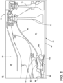
FIG. 2 is an enlarged view of a portion of the turbine engine ofFIG. 1 illustrating a first swirler in a stator of the gas turbine engine and a second swirler in a rotor of the gas turbine engine. -
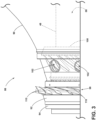
FIG. 3 is a view of the first and second swirlers ofFIG. 2 having a case with a plurality of apertures disposed between the first and second swirlers. -
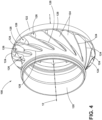
FIG. 4 is a perspective view of the second swirler ofFIG. 2 . -
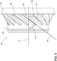
FIG. 5 is a side view of the second swirler ofFIG. 2 . -
FIG. 6 is a side view of a swirler section illustrating the airflow passing from the second swirler. -
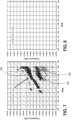
FIG. 7 is a plot illustrating acoustic vibrations generated by a turbine engine without the second swirler ofFIG. 2 . -
FIG. 8 is a plot illustrating the removed acoustic vibrations utilizing the second swirler ofFIG. 3 downstream of the first swirler. - The described embodiments of the present invention are directed to a swirler mounted to a rotor of a turbine engine forward of a turbine section of the engine to reduce rotational speed of fluid provided to the first stage of the turbine section. For purposes of illustration, the present invention will be described with respect to the turbine for an aircraft gas turbine engine. It will be understood, however, that the invention is not so limited and may have general applicability within an engine, including compressors, as well as in non-aircraft applications, such as other mobile applications and non-mobile industrial, commercial, and residential applications.
- As used herein, the term "forward" or "upstream" refers to moving in a direction toward the engine inlet, or a component being relatively closer to the engine inlet as compared to another component. The term "aft" or "downstream" used in conjunction with "forward" or "upstream" refers to a direction toward the rear or outlet of the engine relative to the engine centerline.
- Additionally, as used herein, the terms "radial" or "radially" refer to a dimension extending between a center longitudinal axis of the engine and an outer engine circumference.
- All directional references (e.g., radial, axial, proximal, distal, upper, lower, upward, downward, left, right, lateral, front, back, top, bottom, above, below, vertical, horizontal, clockwise, counterclockwise, upstream, downstream, aft, etc.) are only used for identification purposes to aid the reader's understanding of the present invention, and do not create limitations, particularly as to the position, orientation, or use of the invention. Connection references (e.g., attached, coupled, connected, and joined) are to be construed broadly and can include intermediate members between a collection of elements and relative movement between elements unless otherwise indicated. As such, connection references do not necessarily infer that two elements are directly connected and in fixed relation to one another. The exemplary drawings are for purposes of illustration only and the dimensions, positions, order and relative sizes reflected in the drawings attached hereto can vary.
-
FIG. 1 is a schematic cross-sectional diagram of agas turbine engine 10 for an aircraft. Theengine 10 has a generally longitudinally extending axis orcenterline 12 extending forward 14 toaft 16. Theengine 10 includes, in downstream serial flow relationship, afan section 18 including afan 20, acompressor section 22 including a booster or low pressure (LP)compressor 24 and a high pressure (HP)compressor 26, acombustion section 28 including acombustor 30, aturbine section 32 including a HPturbine 34, and aLP turbine 36, and anexhaust section 38. - The
fan section 18 includes a fan casing 40 surrounding thefan 20. Thefan 20 includes a plurality offan blades 42 disposed radially about thecenterline 12. The HPcompressor 26, thecombustor 30, and the HPturbine 34 form acore 44 of theengine 10, which generates combustion gases. Thecore 44 is surrounded bycore casing 46, which can be coupled with the fan casing 40. - A HP shaft or
spool 48 disposed coaxially about thecenterline 12 of theengine 10 drivingly connects the HPturbine 34 to the HPcompressor 26. A LP shaft orspool 50, which is disposed coaxially about thecenterline 12 of theengine 10 within the larger diameter annular HPspool 48, drivingly connects theLP turbine 36 to theLP compressor 24 andfan 20. - The
LP compressor 24 and the HPcompressor 26 respectively include a plurality ofcompressor stages compressor blades static compressor vanes 60, 62 (also called a nozzle) to compress or pressurize the stream of fluid passing through the stage. In asingle compressor stage multiple compressor blades centerline 12, from a blade platform to a blade tip, while the corresponding static compressor vanes 60, 62 are positioned upstream of and adjacent to therotating blades FIG. 1 were selected for illustrative purposes only, and that other numbers are possible. - The
blades disk 59, which is mounted to the corresponding one of the HP andLP spools own disk vanes core casing 46 in a circumferential arrangement. - The HP
turbine 34 and theLP turbine 36 respectively include a plurality ofturbine stages turbine blades static turbine vanes 72, 74 (also called a nozzle) to extract energy from the stream of fluid passing through the stage. In asingle turbine stage multiple turbine vanes centerline 12, while the correspondingrotating blades static turbine vanes centerline 12, from a blade platform to a blade tip. It is noted that the number of blades, vanes, and turbine stages shown inFIG. 1 were selected for illustrative purposes only, and that other numbers are possible. - The
blades disk 71, which is mounted to the corresponding one of the HP andLP spools own disk vanes core casing 46 in a circumferential arrangement. - The portions of the
engine 10 mounted to and rotating with either or both of thespools rotor 88. The stationary portions of theengine 10 including portions mounted to thecore casing 46 are also referred to individually or collectively as astator 92. - In operation, the airflow exiting the
fan section 18 is split such that a portion of the airflow is channeled into theLP compressor 24, which then supplies pressurizedambient air 76 to the HPcompressor 26, which further pressurizes the ambient air. The pressurizedair 76 from the HPcompressor 26 is mixed with fuel in thecombustor 30 and ignited, thereby generating combustion gases. Some work is extracted from these gases by the HPturbine 34, which drives the HPcompressor 26. The combustion gases are discharged into theLP turbine 36, which extracts additional work to drive theLP compressor 24, and the exhaust gas is ultimately discharged from theengine 10 via theexhaust section 38. The driving of theLP turbine 36 drives theLP spool 50 to rotate thefan 20 and theLP compressor 24. - A remaining portion of the
airflow 78 bypasses theLP compressor 24 andengine core 44 and exits theengine assembly 10 through a stationary vane row, and more particularly an outletguide vane assembly 80, comprising a plurality ofairfoil guide vanes 82, at thefan exhaust side 84. More specifically, a circumferential row of radially extendingairfoil guide vanes 82 are utilized adj acent thefan section 18 to exert some directional control of theairflow 78. - Some of the ambient air supplied by the
fan 20 can bypass theengine core 44 and be used for cooling of portions, especially hot portions, of theengine 10, and/or used to cool or power other aspects of the aircraft. In the context of a turbine engine, the hot portions of the engine are normally thecombustor 30 and components downstream of thecombustor 30, especially theturbine section 32, with the HPturbine 34 being the hottest portion as it is directly downstream of thecombustion section 28. Other sources of cooling fluid can be, but is not limited to, fluid discharged from theLP compressor 24 or theHP compressor 26. This fluid can be bleedair 77 which can include air drawn from the LP orHP compressors combustor 30 as cooling sources for theturbine section 32. This is a common engine configuration, not meant to be limiting. - The
rotor 88 includes all of the elements of theengine core 44 that rotate, such as theHP spool 48,disks 71,blades rotating blades 68 for moving a volume of air through theengine 10. - The
stator 92 includes elements of theengine core 44 that do not rotate, such assupport vanes 62, mounts, and other non-rotating elements in non-limiting examples. - It should be understood that some elements of the
compressor section 22, thecombustion section 28, and theturbine section 32 form therotor 88 and other elements of thecompressor section 22,combustion section 28, and theturbine section 32 form the stator. Thestator 92 can be complementary to therotor 88, positioning the non-rotating elements adjacent the rotating elements of therotor 88 in order to efficiently provide a flow of air driven by theengine core 44. - The
engine 10 further includes aswirler section 86. Theswirler section 86 can be disposed between thecompressor section 22 and theturbine section 32, being fed with a flow of fluid bypassing thecombustor 30. Theswirler section 86 induces a swirl on the flow of fluid. -
FIG. 2 illustrates an enlarged view of theswirler section 86. Arotatable shaft 90, which can be the high pressure turbine shaft couples to theforward-most disk 71 and can rotate with thedisk 71 during engine operation. Theshaft 90 defines a bypass chamber 91 adjacent to thedisks 71. Theswirler section 86 includes afirst seal 94 and asecond seal 96. Thestator 92 meets therotor 88 at thefirst seal 94 and thesecond seal 96. - A
first swirler 98 is disposed between the first andsecond seals first swirler 98 mounts to thestator 92 and is non-rotating. Thefirst swirler 98 induces rotation of an airflow passing through thefirst swirler 98, such as a bypass airflow. A first example for thefirst swirler 98 can be a ring having a plurality of fixed vanes to turn the airflow from being substantially axial to including a tangential component. Another example of thefirst swirler 98 can be an inducer, having a plurality of dedicated flow paths to turn the airflow passing through the inducer. - It should be understood that the swirling airflow generated by the
first swirler 98 is both a circumferential and axial airflow, passing circumferentially around theengine 10 while moving axial in the aft direction. The swirling airflow can be represented by the component of the airflow, which is tangential to the rotation direction, which is referred to as a tangential airflow can be quantified in terms of a Tangential Mach Number indicating the rotational speed of the airflow generated by thefirst swirler 98. Such a Mach number is a function of the speed of sound in the swirling air. Additionally, the Tangential Mach Number can be a function of the radial distance the flow is from the engine centerline. - A
second swirler 100 is disposed downstream from and in fluid communication with thefirst swirler 98. Thesecond swirler 100 is mounted to therotor 88 and is a rotating element. More specifically, thesecond swirler 100 can mount to theHP spool 48 to rotate about theengine centerline 12. Thesecond swirler 100 is separated from thefirst swirler 98 by theshaft 90. A plurality ofapertures 102 is disposed in theshaft 90 between thefirst swirler 98 and thesecond swirler 100. Thefirst swirler 98 is in fluid communication with thesecond swirler 100 through theapertures 102. Thesecond swirler 100 reduces the Tangential Mach Number, or rotational speed of the airflow from thefirst swirler 98 as it enters the bypass chamber 91. - In one particular example, the
second swirler 100 can be a deswirler, as the deswirler reduces the Tangential Mach Number, or rotational speed of the airflow passing through thesecond swirler 100. Alternatively, thesecond swirler 100 can be a swirler similar to thefirst swirler 98, increasing the Tangential Mach Number or rotational speed of the airflow moving through thesecond swirler 100. - Referring to
FIG. 3 , thefirst swirler 98 includes a plurality of circumferentially spacedstatic vanes 110. Thevanes 110 turn an airflow from having an axial direction to having both an axial and a tangential component to the airflow. Downstream from thefirst swirler 98 is theshaft 90, having theapertures 102 circumferentially arranged on theshaft 90 fluidly coupling thefirst swirler 98 to thesecond swirler 100. The cross-sectional area of theapertures 102 as well as the number ofapertures 102 can be used to selectively control the airflow rate provided to thesecond swirler 100 from thefirst swirler 98. Thefirst seal 94 is disposed under thefirst swirler 98, sealing the airflow at the junction between therotating shaft 90 and thefirst swirler 98. - Referring now to
FIG. 4 , thesecond swirler 100 includes aninner band 120 and anouter band 122. Theinner band 120 can mount to theHP spool 48 to rotate thesecond swirler 100, while theouter band 122 can provide a radially exterior terminal surface for thesecond swirler 100. A plurality of circumferentially spacedblades 124 mount between the inner andouter bands blades 124 can be mounted to thebands bands - The
blades 124 are linear and can be plate-like, being flat, defining a plurality oflinear passages 126 between eachadjacent blade 124. Theblades 124 can further include a radiused corner, such as afillet 128, at the junction between the blades and the inner andouter bands blades 124 are disposed at an angle such that rotation of thesecond swirler 100 imparts a tangential speed on the airflow passing through thesecond swirler 100. By varying the number ofblades 124 and the disposition of the same, the Tangential Mach Number of the airflow provided by theblades 124 can be controlled. - According to an example not falling within the scope of the claimed invention, the
blades 124 can be non-linear.Such blades 124 can be arcuate or curved to reduce the rotational speed of the airflow passing through thesecond swirler 100. Such an orientation may be advantageous based upon the rotational speed of thesecond swirler 100, where a linear blade may be less efficient. In another example, theblades 124 need not be flat or plate-like, and can be airfoil-shaped in one non-limiting example, further improving efficiency. - Referring now to
FIG. 5 , using the flat,linear blades 124 as an example, theblades 124 are disposed at an angle to determine the Tangential speed component of the airflow passing through thesecond swirler 100. Ablade axis 140 is defined longitudinally along thelinear blades 124. Ablade angle 142 is defined by theblade axis 140 relative to theengine centerline 12. Theblade angle 142 is between 30 degrees and 75 degrees and can be 60 degrees, while in examples not falling within the scope of the claimed invention, a greater range of angles is contemplated. - It should be understood that the
blade angle 142 can orient theblades 124 to deswirl a flow of air passing through thesecond swirler 100, with thesecond swirler 100 functioning as the deswirler. Deswirling the flow of air reduces the tangential speed of the air passing through thesecond swirler 100. Theblade angle 142 can be adapted to achieve a particular tangential speed for the air passing through thesecond swirler 100. For example, angling theblades 124 at about 30 degrees can significantly reduce the tangential speed of the air passing through thesecond swirler 100 to operate as the deswirler. In another example, angling the blades at about 60 degrees can only slightly reduce the tangential speed of the air moving through thesecond swirler 100 to also function as a deswirler. It is also contemplated that thesecond swirler 100 can increase the tangential speed of the airflow. For example, angling theblades 124 at ablade angle 142 of about 75 degrees can increase the tangential speed component of the airflow passing through thesecond swirler 100, operating as a swirler downstream of thefirst swirler 98. As such, it should be understood that it is contemplated that thesecond swirler 100 can increase or decrease the tangential speed of the airflow passing through thesecond swirler 100 as a function of theblade angle 142. - The operation of the
turbine engine 10, especially thefirst swirler 98 andsecond swirler 100, will be described with respect toFIG. 6 , which illustrates a flow of air bypassing thecombustor 30 can be provided to thefirst swirler 98 as abypass airflow 150. Thebypass airflow 150 can be moving in a substantially axial direction. Thebypass airflow 150 passes through thefirst swirler 98 and turns, having both a circumferential and axial component as swirlingairflow 152. The swirlingairflow 152 can swirl circumferentially around theengine centerline 12 defining a Tangential Mach Number. The Tangential Mach Number for the swirlingairflow 152 is function of the speed of sound in air, defined tangentially to the rotational direction of the airflow. In one example, the tangential speed of the swirlingairflow 152 can be about two times higher than therotor 88 circumferential speed. Similarly, the tangential speed induced by thefirst swirler 98 can be between 80-300% of the rotational speed of therotor 88, for example. - The swirling
airflow 152 can be separated into two airflows by theshaft 90, as aHP turbine airflow 154 and arotor airflow 156. TheHP turbine airflow 154 remains radially outside of theshaft 90, being provided to the first stage of the HP turbine 34 (FIG. 1 ) such as for preventing hot gas ingestion or utilized for engine component cooling. Such rotational speed of theHP turbine airflow 154 requires a higher Tangential Mach Number to maintain proper engine efficiency for interacting with or being provided to the mainstream airflow passing through the engine core 44 (FIG. 1 ). - The remaining portion of the swirling
airflow 152 as therotor airflow 156 passes through theapertures 102 in theshaft 90 and is provided to thesecond swirler 100. Thesecond swirler 100 reduces rotational speed of the swirlingrotor airflow 156 as adeswirled airflow 158. Alternatively, it should be appreciated that thesecond swirler 100 can further increase the rotational speed of the swirlingrotor airflow 156. Theblades 124 are oriented at aparticular blade angle 142 to turn the swirlingairflow 152, to reduce or control the Tangential Mach Number of the swirlingairflow 152 as thedeswirled airflow 158. Thedeswirled airflow 158 includes a swirling airflow tangential speed component to be closer to rotational speed of therotor 88. In one example, thedeswirled airflow 158 can have a Tangential Mach Number less than 0.40. In alternate examples, the Tangential Mach Number for thedeswirled airflow 158 can be less than a predetermined threshold Tangential Mach Number. The threshold Tangential Mach Number is a known value based upon the engine geometry and is independent of the rotational speed of therotor 88 or theparticular engine core 44. Such a threshold can be 0.40 in one non-limiting example and the Tangential Mach Number for thedeswirled airflow 158 is reduced to less than 0.40 by thesecond swirler 100. Such a reduction in the rotational speed of thedeswirled airflow 158 can retard vortex whistle under the disk 71 (FIG. 1 ) of the first stage of theturbine section 32 and minimize acoustic vibration. The retarded vortex whistle energy can be maintained below the threshold Tangential Mach Number necessary to induce interaction with theengine core 44. - In another example, the
blades 124 can be angled at ahigher blade angle 142, such as 75 degrees, and can increase the tangential speed of thedeswirled airflow 158, effectively becoming a swirledairflow 158. For example, if the swirledairflow 152 is moving at twice the speed of therotor 88, thesecond swirler 100, having blades angled at about 75 degrees can increase the tangential speed of the deswirled airflow to about 2.5 times the rotational speed of therotor 88 as the swirledairflow 158. - The swirling
airflow 152 provided by thefirst swirler 98 minimizes losses associated with providing the swirlingairflow 152 first stage of theturbine section 32. Thesecond swirler 100 reduces the rotational speed of the swirledairflow 152 as thedeswirled airflow 158 provided to therotating disk 71 of the highpressure turbine section 34. Without deswirling the swirledairflow 152, the swirlingairflow 152 can generate an airflow instability under thedisk 71 as acoustic vibrations. Referring now toFIGS. 7 and 8 , two plots illustrate suchacoustic vibrations 170. The plots show measured frequencies within theswirler section 86 at a given rotational speed of therotor 88. Such a frequency can be measured between about 2.5k Hertz (Hz) and 3.7k Hz at a rotational speed between about 7k rpm and 9.5k rpm, for example. -
FIG. 7 is representative of anengine core 44 without asecond swirler 100. As the swirledairflow 152 contacts thedisk 71 of the first stage of theturbine section 34, a high frequencyacoustic vibration 170 is generated from thedisk 71. Such an acoustic vibration170 can result in reduced efficiency of the bypass flow or can reduce lifetime of engine parts affected by the airflow instabilities. Thus, it is desirable to reduce or eliminate such an airflow instability. Turning toFIG. 8 , illustrating the acoustic spectrum of anengine core 44 using thesecond swirler 100, it can be appreciated that excitation is removed in the exemplary plot. Thus, utilizing thesecond swirler 100 can increase the efficiency of the bypass flow at thedisk 71 and nearby component lifetime. - It should be understood that reducing the Tangential Mach Number with the
second swirler 100 reduces the tangential speed of thedeswirled airflow 158 while maintaining the heightened rotational speed of the swirlingairflow 152 provided from thefirst swirler 98 to theHP turbine 34. Such a reduction of the speed of thedeswirled airflow 158 reduces airflow instability leading to harmonic vibration and potential resonance generated by the swirlingairflow 152 otherwise contacting interior engine components, such as the disk 71 (FIG. 2 ), while continuing to providing an appropriate Tangential Mach Number to maintain the feed pressures necessary to provide a cooling airflow to downstream components, such as the rotating blades. In one specific example, maintaining the Tangential Mach Number below the threshold can minimize or eliminate acoustic vibration, harmonic vibration, or resonance occurring at natural system frequencies, such as a vortex whistle created at the first stage highpressure turbine disk 71. - A method of swirling fluid within the
turbine engine 10 includes swirling the fluid or airflow from a static portion of theturbine engine 10, such as thestator 92, into a rotor portion, such as therotor 88, of theturbine engine 10 at a speed greater than the rotation of the rotor portion. The fluid is swirled at thefirst swirler 98 as the swirlingairflow 152 provided to the rotor portion. The method can further include deswirling the fluid into the interior of the rotor portion sufficient to maintain a predetermined Tangential Mach Number at thehigh pressure turbine 34. The deswirling can be accomplished with thesecond swirler 100 to reduce the Tangential Mach Number of the fluid provided from the first swirler 98.The method can include reducing the rotational speed of the fluid to prevent acoustic vibration, such as harmonic vibration, that can excite resonance of the rotor portion. Such a prevention can eliminate the incidence of vortex whistling of the rotor portion. - It should be appreciated that an excessive Tangential Mach Number can result in harmonic vibration or resonance, such as vortex whistle within the rotating parts of the
high pressure turbine 34. Such resonance, for example, can occur at the high pressure turbinefirst stage disk 71. Utilizing asecond swirler 100 to minimize the Tangential Mach Number provided to thehigh pressure turbine 34 can reduce or eliminate the incidence of vortex whistle, as well as any other harmonic vibration caused by excessive tangential Mach numbers within therotor 88. Minimizing or eliminating vortex whistle or harmonic vibration can extendhigh pressure turbine 34 androtor 88 lifetime while reducing overall maintenance. - It should be appreciated that application of the disclosed design is not limited to turbine engines with fan and booster sections, but is applicable to turbojets and turbo engines as well, or other engines utilizing swirling airflows.
- This written description uses examples to disclose the invention, including the best mode, and also to enable any person skilled in the art to practice the invention, including making and using any devices or systems and performing any incorporated methods. The patentable scope of the invention is defined by the claims, and may include other examples that occur to those skilled in the art.
Claims (11)
- A turbine engine (10) comprising:an engine core (44) having a compressor section (22), a combustor section (28), and a turbine section (32) in axial arrangement and defining an engine centerline (12), and which are operationally separated into a stator (92) fixed about the centerline and a rotor (88) rotatable about the centerline, wherein the compressor section (22) comprises a compressor (24, 26) and the turbine section (32) comprises a turbine (34, 36);a first swirler (98) provided on the stator for inducing rotation of an airflow passing through the engine core;a second swirler (100) provided on the rotor downstream of and in fluid communication with the first swirler for reducing a rotational speed of the airflow from the first swirler; anda shaft (48, 90) having a plurality of apertures (102) with the shaft (48, 90) disposed between the first swirler (98) and the second swirler (100) and the first swirler (98) being in fluid communication with the second swirler (100) through the apertures (102);whereinthe turbine (34, 36) comprises a turbine disk (71) and a turbine blade (68, 70) mounted to the turbine disk (71); the shaft (48, 90) drivingly connects the turbine (34, 36) to the compressor (24, 26); and the second swirler (100) is mounted to the shaft (48, 90), characterized in thatthe second swirler includes a plurality of circumferentially spaced blades, wherein the circumferentially spaced blades are linear, and wherein at least some of the blades are angled between 30 and 75 degrees relative to the engine centreline.
- The turbine engine (10) of claim 1, wherein at least some of the blades are angled at 60 degrees relative to the engine centerline.
- The turbine engine (10) of claim 1, wherein the blades have an airfoil shape.
- The turbine engine (10) of claim 1, wherein the first swirler includes a plurality of circumferentially spaced vanes to induce circumferential rotation of the airflow.
- The turbine engine (10) of claim 1, wherein the first swirler induces rotation of the airflow to between 80 - 300% of the rotational speed of the rotor.
- The turbine engine (10) of claim 5, wherein the second swirler is a deswirler to reduce the rotational speed of the airflow from the first swirler.
- The turbine engine (10) of claim 1, wherein reduced rotational speed minimizes harmonic vibration at the turbine section.
- The turbine engine (10) of claim 1, wherein the second swirler is a deswirler.
- The turbine engine (10) of claim 8, wherein the deswirler retards vortex whistle of a disk at the turbine section.
- The turbine engine (10) of claim 1, wherein the second swirler reduces the rotational speed of the airflow below a predetermined threshold tangential Mach number.
- A method of swirling a fluid within a turbine engine (10) according to claim 1, the method comprising:swirling, by the first swirler (98), the fluid from a static portion of the turbine engine into a rotor portion of the turbine engine at a speed greater than the rotor portion to define a first swirled flow; andswirling, by the second swirler (100), the first swirled flow within an interior of the rotor portion to maintain a predetermined Tangential Mach Number at a high pressure turbine.
Applications Claiming Priority (2)
| Application Number | Priority Date | Filing Date | Title |
|---|---|---|---|
| PL417315A PL417315A1 (en) | 2016-05-25 | 2016-05-25 | Turbine engine with swirl vane |
| PCT/US2017/033237 WO2018026413A2 (en) | 2016-05-25 | 2017-05-18 | Turbine engine with a swirler |
Publications (2)
| Publication Number | Publication Date |
|---|---|
| EP3464822A2 EP3464822A2 (en) | 2019-04-10 |
| EP3464822B1 true EP3464822B1 (en) | 2023-09-06 |
Family
ID=60473160
Family Applications (1)
| Application Number | Title | Priority Date | Filing Date |
|---|---|---|---|
| EP17822062.0A Active EP3464822B1 (en) | 2016-05-25 | 2017-05-18 | Turbine engine with a swirler |
Country Status (6)
| Country | Link |
|---|---|
| US (1) | US11060405B2 (en) |
| EP (1) | EP3464822B1 (en) |
| CN (1) | CN109477388B (en) |
| CA (1) | CA3025324C (en) |
| PL (1) | PL417315A1 (en) |
| WO (1) | WO2018026413A2 (en) |
Families Citing this family (3)
| Publication number | Priority date | Publication date | Assignee | Title |
|---|---|---|---|---|
| US11802693B2 (en) * | 2021-04-16 | 2023-10-31 | General Electric Company | Combustor swirl vane apparatus |
| CN113834094B (en) * | 2021-09-15 | 2022-11-01 | 中国船舶重工集团公司第七0三研究所 | Nozzle with tangential rotational flow structure |
| US11959401B1 (en) | 2023-03-24 | 2024-04-16 | Honeywell International Inc. | Deswirl system for gas turbine engine |
Family Cites Families (17)
| Publication number | Priority date | Publication date | Assignee | Title |
|---|---|---|---|---|
| US3565545A (en) * | 1969-01-29 | 1971-02-23 | Melvin Bobo | Cooling of turbine rotors in gas turbine engines |
| US4541774A (en) * | 1980-05-01 | 1985-09-17 | General Electric Company | Turbine cooling air deswirler |
| GB2075123B (en) * | 1980-05-01 | 1983-11-16 | Gen Electric | Turbine cooling air deswirler |
| US4807433A (en) * | 1983-05-05 | 1989-02-28 | General Electric Company | Turbine cooling air modulation |
| US4541744A (en) * | 1984-11-15 | 1985-09-17 | General Motors Coporation | Unitized bearing assembly with moldable race members and labryinth seal |
| US4882902A (en) * | 1986-04-30 | 1989-11-28 | General Electric Company | Turbine cooling air transferring apparatus |
| US5140819A (en) | 1989-09-28 | 1992-08-25 | Sundstrand Corporation | Turbine inlet silencer |
| US5373691A (en) | 1993-06-23 | 1994-12-20 | Allied-Signal Inc. | Inlet guide vane dewhistler |
| US6398487B1 (en) | 2000-07-14 | 2002-06-04 | General Electric Company | Methods and apparatus for supplying cooling airflow in turbine engines |
| IT1319552B1 (en) | 2000-12-15 | 2003-10-20 | Nuovo Pignone Spa | SYSTEM FOR ADDUCTION OF COOLING AIR IN A GAS TURBINE |
| US6468032B2 (en) * | 2000-12-18 | 2002-10-22 | Pratt & Whitney Canada Corp. | Further cooling of pre-swirl flow entering cooled rotor aerofoils |
| US6540477B2 (en) * | 2001-05-21 | 2003-04-01 | General Electric Company | Turbine cooling circuit |
| US7442006B2 (en) | 2005-08-15 | 2008-10-28 | Honeywell International Inc. | Integral diffuser and deswirler with continuous flow path deflected at assembly |
| US8172506B2 (en) * | 2008-11-26 | 2012-05-08 | General Electric Company | Method and system for cooling engine components |
| US8584469B2 (en) | 2010-04-12 | 2013-11-19 | Siemens Energy, Inc. | Cooling fluid pre-swirl assembly for a gas turbine engine |
| KR101509382B1 (en) * | 2014-01-15 | 2015-04-07 | 두산중공업 주식회사 | Gas turbine having damping clamp |
| EP2942483B2 (en) * | 2014-04-01 | 2022-09-28 | Raytheon Technologies Corporation | Vented tangential on-board injector for a gas turbine engine |
-
2016
- 2016-05-25 PL PL417315A patent/PL417315A1/en unknown
-
2017
- 2017-05-18 US US16/098,515 patent/US11060405B2/en active Active
- 2017-05-18 CN CN201780031939.6A patent/CN109477388B/en active Active
- 2017-05-18 CA CA3025324A patent/CA3025324C/en active Active
- 2017-05-18 WO PCT/US2017/033237 patent/WO2018026413A2/en unknown
- 2017-05-18 EP EP17822062.0A patent/EP3464822B1/en active Active
Also Published As
| Publication number | Publication date |
|---|---|
| PL417315A1 (en) | 2017-12-04 |
| CA3025324A1 (en) | 2018-02-08 |
| CN109477388A (en) | 2019-03-15 |
| EP3464822A2 (en) | 2019-04-10 |
| CA3025324C (en) | 2021-06-15 |
| CN109477388B (en) | 2021-09-17 |
| WO2018026413A2 (en) | 2018-02-08 |
| US20200157940A1 (en) | 2020-05-21 |
| WO2018026413A3 (en) | 2018-05-11 |
| US11060405B2 (en) | 2021-07-13 |
Similar Documents
| Publication | Publication Date | Title |
|---|---|---|
| US20200277862A1 (en) | Airfoil for a turbine engine | |
| US20170248155A1 (en) | Centrifugal compressor diffuser passage boundary layer control | |
| CN107084004B (en) | Impingement hole for a turbine engine component | |
| US20180230839A1 (en) | Turbine engine shroud assembly | |
| US20190003323A1 (en) | Airfoil assembly with a scalloped flow surface | |
| CN109838281A (en) | Shield for gas-turbine unit | |
| JP2012233475A (en) | Centrifugal compressor assembly with stator vane row | |
| RU2619327C2 (en) | Turbomachine unit | |
| EP3255248A1 (en) | Engine component for a turbine engine | |
| JP2017089624A (en) | Gas turbine engine having flow control surface with cooling conduit | |
| EP3464822B1 (en) | Turbine engine with a swirler | |
| US20220106884A1 (en) | Turbine engine component with deflector | |
| US10450874B2 (en) | Airfoil for a gas turbine engine | |
| EP3190261A1 (en) | Stator rim structure for a turbine engine | |
| US10408075B2 (en) | Turbine engine with a rim seal between the rotor and stator | |
| US9291071B2 (en) | Turbine nozzle baffle | |
| US20220220854A1 (en) | Turbine engine with an airfoil having a set of dimples | |
| US20180230812A1 (en) | Film hole arrangement for a turbine engine | |
| US10626797B2 (en) | Turbine engine compressor with a cooling circuit | |
| US10774661B2 (en) | Shroud for a turbine engine | |
| US11939880B1 (en) | Airfoil assembly with flow surface | |
| US11401835B2 (en) | Turbine center frame |
Legal Events
| Date | Code | Title | Description |
|---|---|---|---|
| STAA | Information on the status of an ep patent application or granted ep patent |
Free format text: STATUS: UNKNOWN |
|
| STAA | Information on the status of an ep patent application or granted ep patent |
Free format text: STATUS: THE INTERNATIONAL PUBLICATION HAS BEEN MADE |
|
| PUAI | Public reference made under article 153(3) epc to a published international application that has entered the european phase |
Free format text: ORIGINAL CODE: 0009012 |
|
| STAA | Information on the status of an ep patent application or granted ep patent |
Free format text: STATUS: REQUEST FOR EXAMINATION WAS MADE |
|
| 17P | Request for examination filed |
Effective date: 20190102 |
|
| AK | Designated contracting states |
Kind code of ref document: A2 Designated state(s): AL AT BE BG CH CY CZ DE DK EE ES FI FR GB GR HR HU IE IS IT LI LT LU LV MC MK MT NL NO PL PT RO RS SE SI SK SM TR |
|
| AX | Request for extension of the european patent |
Extension state: BA ME |
|
| STAA | Information on the status of an ep patent application or granted ep patent |
Free format text: STATUS: REQUEST FOR EXAMINATION WAS MADE |
|
| DAV | Request for validation of the european patent (deleted) | ||
| DAX | Request for extension of the european patent (deleted) | ||
| STAA | Information on the status of an ep patent application or granted ep patent |
Free format text: STATUS: EXAMINATION IS IN PROGRESS |
|
| 17Q | First examination report despatched |
Effective date: 20210504 |
|
| STAA | Information on the status of an ep patent application or granted ep patent |
Free format text: STATUS: EXAMINATION IS IN PROGRESS |
|
| GRAP | Despatch of communication of intention to grant a patent |
Free format text: ORIGINAL CODE: EPIDOSNIGR1 |
|
| STAA | Information on the status of an ep patent application or granted ep patent |
Free format text: STATUS: GRANT OF PATENT IS INTENDED |
|
| INTG | Intention to grant announced |
Effective date: 20230404 |
|
| GRAS | Grant fee paid |
Free format text: ORIGINAL CODE: EPIDOSNIGR3 |
|
| GRAA | (expected) grant |
Free format text: ORIGINAL CODE: 0009210 |
|
| STAA | Information on the status of an ep patent application or granted ep patent |
Free format text: STATUS: THE PATENT HAS BEEN GRANTED |
|
| P01 | Opt-out of the competence of the unified patent court (upc) registered |
Effective date: 20230724 |
|
| AK | Designated contracting states |
Kind code of ref document: B1 Designated state(s): AL AT BE BG CH CY CZ DE DK EE ES FI FR GB GR HR HU IE IS IT LI LT LU LV MC MK MT NL NO PL PT RO RS SE SI SK SM TR |
|
| REG | Reference to a national code |
Ref country code: GB Ref legal event code: FG4D |
|
| REG | Reference to a national code |
Ref country code: CH Ref legal event code: EP |
|
| REG | Reference to a national code |
Ref country code: IE Ref legal event code: FG4D |
|
| REG | Reference to a national code |
Ref country code: DE Ref legal event code: R096 Ref document number: 602017073873 Country of ref document: DE |
|
| REG | Reference to a national code |
Ref country code: LT Ref legal event code: MG9D |
|
| REG | Reference to a national code |
Ref country code: NL Ref legal event code: MP Effective date: 20230906 |
|
| PG25 | Lapsed in a contracting state [announced via postgrant information from national office to epo] |
Ref country code: GR Free format text: LAPSE BECAUSE OF FAILURE TO SUBMIT A TRANSLATION OF THE DESCRIPTION OR TO PAY THE FEE WITHIN THE PRESCRIBED TIME-LIMIT Effective date: 20231207 |
|
| PG25 | Lapsed in a contracting state [announced via postgrant information from national office to epo] |
Ref country code: SE Free format text: LAPSE BECAUSE OF FAILURE TO SUBMIT A TRANSLATION OF THE DESCRIPTION OR TO PAY THE FEE WITHIN THE PRESCRIBED TIME-LIMIT Effective date: 20230906 Ref country code: RS Free format text: LAPSE BECAUSE OF FAILURE TO SUBMIT A TRANSLATION OF THE DESCRIPTION OR TO PAY THE FEE WITHIN THE PRESCRIBED TIME-LIMIT Effective date: 20230906 Ref country code: NO Free format text: LAPSE BECAUSE OF FAILURE TO SUBMIT A TRANSLATION OF THE DESCRIPTION OR TO PAY THE FEE WITHIN THE PRESCRIBED TIME-LIMIT Effective date: 20231206 Ref country code: LV Free format text: LAPSE BECAUSE OF FAILURE TO SUBMIT A TRANSLATION OF THE DESCRIPTION OR TO PAY THE FEE WITHIN THE PRESCRIBED TIME-LIMIT Effective date: 20230906 Ref country code: LT Free format text: LAPSE BECAUSE OF FAILURE TO SUBMIT A TRANSLATION OF THE DESCRIPTION OR TO PAY THE FEE WITHIN THE PRESCRIBED TIME-LIMIT Effective date: 20230906 Ref country code: HR Free format text: LAPSE BECAUSE OF FAILURE TO SUBMIT A TRANSLATION OF THE DESCRIPTION OR TO PAY THE FEE WITHIN THE PRESCRIBED TIME-LIMIT Effective date: 20230906 Ref country code: GR Free format text: LAPSE BECAUSE OF FAILURE TO SUBMIT A TRANSLATION OF THE DESCRIPTION OR TO PAY THE FEE WITHIN THE PRESCRIBED TIME-LIMIT Effective date: 20231207 Ref country code: FI Free format text: LAPSE BECAUSE OF FAILURE TO SUBMIT A TRANSLATION OF THE DESCRIPTION OR TO PAY THE FEE WITHIN THE PRESCRIBED TIME-LIMIT Effective date: 20230906 |
|
| REG | Reference to a national code |
Ref country code: AT Ref legal event code: MK05 Ref document number: 1608811 Country of ref document: AT Kind code of ref document: T Effective date: 20230906 |
|
| PG25 | Lapsed in a contracting state [announced via postgrant information from national office to epo] |
Ref country code: NL Free format text: LAPSE BECAUSE OF FAILURE TO SUBMIT A TRANSLATION OF THE DESCRIPTION OR TO PAY THE FEE WITHIN THE PRESCRIBED TIME-LIMIT Effective date: 20230906 |
|
| PG25 | Lapsed in a contracting state [announced via postgrant information from national office to epo] |
Ref country code: IS Free format text: LAPSE BECAUSE OF FAILURE TO SUBMIT A TRANSLATION OF THE DESCRIPTION OR TO PAY THE FEE WITHIN THE PRESCRIBED TIME-LIMIT Effective date: 20240106 |
|
| PG25 | Lapsed in a contracting state [announced via postgrant information from national office to epo] |
Ref country code: AT Free format text: LAPSE BECAUSE OF FAILURE TO SUBMIT A TRANSLATION OF THE DESCRIPTION OR TO PAY THE FEE WITHIN THE PRESCRIBED TIME-LIMIT Effective date: 20230906 |
|
| PG25 | Lapsed in a contracting state [announced via postgrant information from national office to epo] |
Ref country code: ES Free format text: LAPSE BECAUSE OF FAILURE TO SUBMIT A TRANSLATION OF THE DESCRIPTION OR TO PAY THE FEE WITHIN THE PRESCRIBED TIME-LIMIT Effective date: 20230906 |
|
| PG25 | Lapsed in a contracting state [announced via postgrant information from national office to epo] |
Ref country code: SM Free format text: LAPSE BECAUSE OF FAILURE TO SUBMIT A TRANSLATION OF THE DESCRIPTION OR TO PAY THE FEE WITHIN THE PRESCRIBED TIME-LIMIT Effective date: 20230906 Ref country code: RO Free format text: LAPSE BECAUSE OF FAILURE TO SUBMIT A TRANSLATION OF THE DESCRIPTION OR TO PAY THE FEE WITHIN THE PRESCRIBED TIME-LIMIT Effective date: 20230906 Ref country code: IS Free format text: LAPSE BECAUSE OF FAILURE TO SUBMIT A TRANSLATION OF THE DESCRIPTION OR TO PAY THE FEE WITHIN THE PRESCRIBED TIME-LIMIT Effective date: 20240106 Ref country code: ES Free format text: LAPSE BECAUSE OF FAILURE TO SUBMIT A TRANSLATION OF THE DESCRIPTION OR TO PAY THE FEE WITHIN THE PRESCRIBED TIME-LIMIT Effective date: 20230906 Ref country code: EE Free format text: LAPSE BECAUSE OF FAILURE TO SUBMIT A TRANSLATION OF THE DESCRIPTION OR TO PAY THE FEE WITHIN THE PRESCRIBED TIME-LIMIT Effective date: 20230906 Ref country code: CZ Free format text: LAPSE BECAUSE OF FAILURE TO SUBMIT A TRANSLATION OF THE DESCRIPTION OR TO PAY THE FEE WITHIN THE PRESCRIBED TIME-LIMIT Effective date: 20230906 Ref country code: AT Free format text: LAPSE BECAUSE OF FAILURE TO SUBMIT A TRANSLATION OF THE DESCRIPTION OR TO PAY THE FEE WITHIN THE PRESCRIBED TIME-LIMIT Effective date: 20230906 Ref country code: SK Free format text: LAPSE BECAUSE OF FAILURE TO SUBMIT A TRANSLATION OF THE DESCRIPTION OR TO PAY THE FEE WITHIN THE PRESCRIBED TIME-LIMIT Effective date: 20230906 Ref country code: PT Free format text: LAPSE BECAUSE OF FAILURE TO SUBMIT A TRANSLATION OF THE DESCRIPTION OR TO PAY THE FEE WITHIN THE PRESCRIBED TIME-LIMIT Effective date: 20240108 |