EP3464822B1 - Turbinenmotor mit verwirbler - Google Patents
Turbinenmotor mit verwirbler Download PDFInfo
- Publication number
- EP3464822B1 EP3464822B1 EP17822062.0A EP17822062A EP3464822B1 EP 3464822 B1 EP3464822 B1 EP 3464822B1 EP 17822062 A EP17822062 A EP 17822062A EP 3464822 B1 EP3464822 B1 EP 3464822B1
- Authority
- EP
- European Patent Office
- Prior art keywords
- swirler
- turbine
- engine
- airflow
- turbine engine
- Prior art date
- Legal status (The legal status is an assumption and is not a legal conclusion. Google has not performed a legal analysis and makes no representation as to the accuracy of the status listed.)
- Active
Links
- 239000012530 fluid Substances 0.000 claims description 22
- 238000000034 method Methods 0.000 claims description 8
- 230000003068 static effect Effects 0.000 claims description 8
- 238000004891 communication Methods 0.000 claims description 5
- 230000001939 inductive effect Effects 0.000 claims description 2
- 239000003570 air Substances 0.000 description 16
- 239000007789 gas Substances 0.000 description 13
- 238000002485 combustion reaction Methods 0.000 description 7
- 238000001816 cooling Methods 0.000 description 6
- 238000011144 upstream manufacturing Methods 0.000 description 4
- 239000012080 ambient air Substances 0.000 description 3
- 239000000567 combustion gas Substances 0.000 description 3
- 239000000411 inducer Substances 0.000 description 3
- 238000010586 diagram Methods 0.000 description 2
- 230000005284 excitation Effects 0.000 description 2
- 239000000284 extract Substances 0.000 description 2
- 238000005266 casting Methods 0.000 description 1
- 230000000295 complement effect Effects 0.000 description 1
- 239000012809 cooling fluid Substances 0.000 description 1
- 230000008878 coupling Effects 0.000 description 1
- 238000010168 coupling process Methods 0.000 description 1
- 238000005859 coupling reaction Methods 0.000 description 1
- 230000037406 food intake Effects 0.000 description 1
- 239000000446 fuel Substances 0.000 description 1
- 230000003993 interaction Effects 0.000 description 1
- 238000012423 maintenance Methods 0.000 description 1
- 230000002265 prevention Effects 0.000 description 1
- 238000007789 sealing Methods 0.000 description 1
- 238000001228 spectrum Methods 0.000 description 1
- 238000003466 welding Methods 0.000 description 1
Images


Classifications
-
- F—MECHANICAL ENGINEERING; LIGHTING; HEATING; WEAPONS; BLASTING
- F01—MACHINES OR ENGINES IN GENERAL; ENGINE PLANTS IN GENERAL; STEAM ENGINES
- F01D—NON-POSITIVE DISPLACEMENT MACHINES OR ENGINES, e.g. STEAM TURBINES
- F01D5/00—Blades; Blade-carrying members; Heating, heat-insulating, cooling or antivibration means on the blades or the members
- F01D5/12—Blades
- F01D5/14—Form or construction
-
- F—MECHANICAL ENGINEERING; LIGHTING; HEATING; WEAPONS; BLASTING
- F01—MACHINES OR ENGINES IN GENERAL; ENGINE PLANTS IN GENERAL; STEAM ENGINES
- F01D—NON-POSITIVE DISPLACEMENT MACHINES OR ENGINES, e.g. STEAM TURBINES
- F01D5/00—Blades; Blade-carrying members; Heating, heat-insulating, cooling or antivibration means on the blades or the members
- F01D5/02—Blade-carrying members, e.g. rotors
- F01D5/08—Heating, heat-insulating or cooling means
- F01D5/081—Cooling fluid being directed on the side of the rotor disc or at the roots of the blades
-
- F—MECHANICAL ENGINEERING; LIGHTING; HEATING; WEAPONS; BLASTING
- F05—INDEXING SCHEMES RELATING TO ENGINES OR PUMPS IN VARIOUS SUBCLASSES OF CLASSES F01-F04
- F05D—INDEXING SCHEME FOR ASPECTS RELATING TO NON-POSITIVE-DISPLACEMENT MACHINES OR ENGINES, GAS-TURBINES OR JET-PROPULSION PLANTS
- F05D2220/00—Application
- F05D2220/30—Application in turbines
-
- F—MECHANICAL ENGINEERING; LIGHTING; HEATING; WEAPONS; BLASTING
- F05—INDEXING SCHEMES RELATING TO ENGINES OR PUMPS IN VARIOUS SUBCLASSES OF CLASSES F01-F04
- F05D—INDEXING SCHEME FOR ASPECTS RELATING TO NON-POSITIVE-DISPLACEMENT MACHINES OR ENGINES, GAS-TURBINES OR JET-PROPULSION PLANTS
- F05D2240/00—Components
- F05D2240/10—Stators
- F05D2240/12—Fluid guiding means, e.g. vanes
- F05D2240/127—Vortex generators, turbulators, or the like, for mixing
-
- F—MECHANICAL ENGINEERING; LIGHTING; HEATING; WEAPONS; BLASTING
- F05—INDEXING SCHEMES RELATING TO ENGINES OR PUMPS IN VARIOUS SUBCLASSES OF CLASSES F01-F04
- F05D—INDEXING SCHEME FOR ASPECTS RELATING TO NON-POSITIVE-DISPLACEMENT MACHINES OR ENGINES, GAS-TURBINES OR JET-PROPULSION PLANTS
- F05D2240/00—Components
- F05D2240/10—Stators
- F05D2240/12—Fluid guiding means, e.g. vanes
- F05D2240/129—Cascades, i.e. assemblies of similar profiles acting in parallel
-
- F—MECHANICAL ENGINEERING; LIGHTING; HEATING; WEAPONS; BLASTING
- F05—INDEXING SCHEMES RELATING TO ENGINES OR PUMPS IN VARIOUS SUBCLASSES OF CLASSES F01-F04
- F05D—INDEXING SCHEME FOR ASPECTS RELATING TO NON-POSITIVE-DISPLACEMENT MACHINES OR ENGINES, GAS-TURBINES OR JET-PROPULSION PLANTS
- F05D2260/00—Function
- F05D2260/14—Preswirling
-
- F—MECHANICAL ENGINEERING; LIGHTING; HEATING; WEAPONS; BLASTING
- F05—INDEXING SCHEMES RELATING TO ENGINES OR PUMPS IN VARIOUS SUBCLASSES OF CLASSES F01-F04
- F05D—INDEXING SCHEME FOR ASPECTS RELATING TO NON-POSITIVE-DISPLACEMENT MACHINES OR ENGINES, GAS-TURBINES OR JET-PROPULSION PLANTS
- F05D2260/00—Function
- F05D2260/96—Preventing, counteracting or reducing vibration or noise
-
- Y—GENERAL TAGGING OF NEW TECHNOLOGICAL DEVELOPMENTS; GENERAL TAGGING OF CROSS-SECTIONAL TECHNOLOGIES SPANNING OVER SEVERAL SECTIONS OF THE IPC; TECHNICAL SUBJECTS COVERED BY FORMER USPC CROSS-REFERENCE ART COLLECTIONS [XRACs] AND DIGESTS
- Y02—TECHNOLOGIES OR APPLICATIONS FOR MITIGATION OR ADAPTATION AGAINST CLIMATE CHANGE
- Y02T—CLIMATE CHANGE MITIGATION TECHNOLOGIES RELATED TO TRANSPORTATION
- Y02T50/00—Aeronautics or air transport
- Y02T50/60—Efficient propulsion technologies, e.g. for aircraft
Definitions
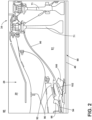
- stator 92 can be complementary to the rotor 88, positioning the non-rotating elements adjacent the rotating elements of the rotor 88 in order to efficiently provide a flow of air driven by the engine core 44.
- the engine 10 further includes a swirler section 86.
- the swirler section 86 can be disposed between the compressor section 22 and the turbine section 32, being fed with a flow of fluid bypassing the combustor 30.
- the swirler section 86 induces a swirl on the flow of fluid.
- FIG. 2 illustrates an enlarged view of the swirler section 86.
- a rotatable shaft 90 which can be the high pressure turbine shaft couples to the forward-most disk 71 and can rotate with the disk 71 during engine operation.
- the shaft 90 defines a bypass chamber 91 adjacent to the disks 71.
- the swirler section 86 includes a first seal 94 and a second seal 96.
- the stator 92 meets the rotor 88 at the first seal 94 and the second seal 96.
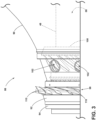
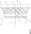
- the first swirler 98 includes a plurality of circumferentially spaced static vanes 110.
- the vanes 110 turn an airflow from having an axial direction to having both an axial and a tangential component to the airflow.
- Downstream from the first swirler 98 is the shaft 90, having the apertures 102 circumferentially arranged on the shaft 90 fluidly coupling the first swirler 98 to the second swirler 100.
- the cross-sectional area of the apertures 102 as well as the number of apertures 102 can be used to selectively control the airflow rate provided to the second swirler 100 from the first swirler 98.
- the first seal 94 is disposed under the first swirler 98, sealing the airflow at the junction between the rotating shaft 90 and the first swirler 98.
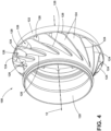
- the second swirler 100 can increase the tangential speed of the airflow. For example, angling the blades 124 at a blade angle 142 of about 75 degrees can increase the tangential speed component of the airflow passing through the second swirler 100, operating as a swirler downstream of the first swirler 98. As such, it should be understood that it is contemplated that the second swirler 100 can increase or decrease the tangential speed of the airflow passing through the second swirler 100 as a function of the blade angle 142.
- the swirling airflow 152 can be separated into two airflows by the shaft 90, as a HP turbine airflow 154 and a rotor airflow 156.
- the HP turbine airflow 154 remains radially outside of the shaft 90, being provided to the first stage of the HP turbine 34 ( FIG. 1 ) such as for preventing hot gas ingestion or utilized for engine component cooling.
- Such rotational speed of the HP turbine airflow 154 requires a higher Tangential Mach Number to maintain proper engine efficiency for interacting with or being provided to the mainstream airflow passing through the engine core 44 ( FIG. 1 ).
- Such a reduction in the rotational speed of the deswirled airflow 158 can retard vortex whistle under the disk 71 ( FIG. 1 ) of the first stage of the turbine section 32 and minimize acoustic vibration.
- the retarded vortex whistle energy can be maintained below the threshold Tangential Mach Number necessary to induce interaction with the engine core 44.
- the blades 124 can be angled at a higher blade angle 142, such as 75 degrees, and can increase the tangential speed of the deswirled airflow 158, effectively becoming a swirled airflow 158.
- the second swirler 100 having blades angled at about 75 degrees can increase the tangential speed of the deswirled airflow to about 2.5 times the rotational speed of the rotor 88 as the swirled airflow 158.
- the swirling airflow 152 provided by the first swirler 98 minimizes losses associated with providing the swirling airflow 152 first stage of the turbine section 32.
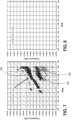
- the second swirler 100 reduces the rotational speed of the swirled airflow 152 as the deswirled airflow 158 provided to the rotating disk 71 of the high pressure turbine section 34. Without deswirling the swirled airflow 152, the swirling airflow 152 can generate an airflow instability under the disk 71 as acoustic vibrations. Referring now to FIGS. 7 and 8 , two plots illustrate such acoustic vibrations 170.
- the plots show measured frequencies within the swirler section 86 at a given rotational speed of the rotor 88. Such a frequency can be measured between about 2.5k Hertz (Hz) and 3.7k Hz at a rotational speed between about 7k rpm and 9.5k rpm, for example.
- FIG. 7 is representative of an engine core 44 without a second swirler 100.
- a high frequency acoustic vibration 170 is generated from the disk 71.
- Such an acoustic vibration170 can result in reduced efficiency of the bypass flow or can reduce lifetime of engine parts affected by the airflow instabilities. Thus, it is desirable to reduce or eliminate such an airflow instability.
- FIG. 8 illustrating the acoustic spectrum of an engine core 44 using the second swirler 100, it can be appreciated that excitation is removed in the exemplary plot.
- utilizing the second swirler 100 can increase the efficiency of the bypass flow at the disk 71 and nearby component lifetime.
- reducing the Tangential Mach Number with the second swirler 100 reduces the tangential speed of the deswirled airflow 158 while maintaining the heightened rotational speed of the swirling airflow 152 provided from the first swirler 98 to the HP turbine 34.
- Such a reduction of the speed of the deswirled airflow 158 reduces airflow instability leading to harmonic vibration and potential resonance generated by the swirling airflow 152 otherwise contacting interior engine components, such as the disk 71 ( FIG. 2 ), while continuing to providing an appropriate Tangential Mach Number to maintain the feed pressures necessary to provide a cooling airflow to downstream components, such as the rotating blades.
- maintaining the Tangential Mach Number below the threshold can minimize or eliminate acoustic vibration, harmonic vibration, or resonance occurring at natural system frequencies, such as a vortex whistle created at the first stage high pressure turbine disk 71.
- a method of swirling fluid within the turbine engine 10 includes swirling the fluid or airflow from a static portion of the turbine engine 10, such as the stator 92, into a rotor portion, such as the rotor 88, of the turbine engine 10 at a speed greater than the rotation of the rotor portion.
- the fluid is swirled at the first swirler 98 as the swirling airflow 152 provided to the rotor portion.
- the method can further include deswirling the fluid into the interior of the rotor portion sufficient to maintain a predetermined Tangential Mach Number at the high pressure turbine 34.
- the deswirling can be accomplished with the second swirler 100 to reduce the Tangential Mach Number of the fluid provided from the first swirler 98.
- the method can include reducing the rotational speed of the fluid to prevent acoustic vibration, such as harmonic vibration, that can excite resonance of the rotor portion. Such a prevention can eliminate the incidence of vortex whistling of the rotor portion.
Landscapes
- Engineering & Computer Science (AREA)
- Mechanical Engineering (AREA)
- General Engineering & Computer Science (AREA)
- Structures Of Non-Positive Displacement Pumps (AREA)
- Turbine Rotor Nozzle Sealing (AREA)
Claims (11)
- Turbinentriebwerk (10), umfassend:einen Triebwerkskern (44), der einen Kompressorbereich (22), einen Brennkammerbereich (28) und einen Turbinenbereich (32) in axialer Anordnung aufweist und eine Triebswerksmittellinie (12) definiert, und die in einen Stator (92), der um die Mittellinie herum fixiert ist, und einen Rotor (88), der um die Mittellinie rotierbar ist, betriebsmäßig getrennt sind, wobei der Kompressorbereich (22) einen Kompressor (24, 26) umfasst und der Turbinenbereich (32) eine Turbine (34, 36) umfasst;ein erstes Wirbelblech (98), das an dem Stator bereitgestellt ist, zum Induzieren einer Rotation eines Luftstroms, der durch den Triebwerkskern hindurchgeht;ein zweites Wirbelblech (100), das an dem Rotor stromabwärts von und in Fluidkommunikation mit dem ersten Wirbelblech bereitgestellt ist, zum Reduzieren einer Rotationsgeschwindigkeit des Luftstroms von dem ersten Wirbelblech; undeine Welle (48, 90), die eine Vielzahl von Öffnungen (102) mit der Welle (48, 90) aufweist, die zwischen dem ersten Wirbelblech (98) und dem zweiten Wirbelblech (100) angeordnet ist, und wobei das erste Wirbelblech (98) mit dem zweiten Wirbelblech (100) durch die Öffnungen (102) in Fluidkommunikation ist;wobeidie Turbine (34, 36) eine Turbinenscheibe (71) und eine Turbinenschaufel (68, 70) umfasst, die an der Turbinenscheibe (71) montiert ist; die Welle (48, 90) die Turbine (34, 36) mit dem Kompressor (24, 26) antriebsmäßig verbindet; und das zweite Wirbelblech (100) an der Welle (48, 90) montiert ist, dadurch gekennzeichnet, dassdas zweite Wirbelblech eine Vielzahl von in Umfangsrichtung beabstandeten Schaufeln einschließt, wobei die in Umfangsrichtung beabstandeten Schaufeln linear sind, und wobei mindestens einige der Schaufeln zwischen 30 und 75 Grad relativ zu der Triebwerksmittellinie abgewinkelt sind.
- Turbinentriebwerk (10) nach Anspruch 1, wobei mindestens einige der Schaufeln um 60 Grad relativ zu der Triebwerksmittellinie abgewinkelt sind.
- Turbinentriebwerk (10) nach Anspruch 1, wobei die Schaufeln eine aerodynamische Form aufweisen.
- Turbinentriebwerk (10) nach Anspruch 1, wobei das erste Wirbelblech eine Vielzahl von in Umfangsrichtung beabstandeten Schaufeln einschließt, um eine Umfangsrotation des Luftstroms zu induzieren.
- Turbinentriebwerk (10) nach Anspruch 1, wobei das erste Wirbelblech eine Rotation des Luftstroms auf zwischen 80-300 % der Rotationsgeschwindigkeit des Rotors induziert.
- Turbinentriebwerk (10) nach Anspruch 5, wobei das zweite Wirbelblech ein Entwirbelungsblech ist, um die Rotationsgeschwindigkeit des Luftstroms von dem ersten Wirbelblech zu reduzieren.
- Turbinentriebwerk (10) nach Anspruch 1, wobei die reduzierte Rotationsgeschwindigkeit die harmonische Vibration an dem Turbinenbereich minimiert.
- Turbinentriebwerk (10) nach Anspruch 1, wobei das zweite Wirbelblech ein Entwirbelungsblech ist.
- Turbinentriebwerk (10) nach Anspruch 8, wobei das Entwirbelungsblech ein Vortex-Pfeifen einer Scheibe an dem Turbinenbereich zurückhält.
- Turbinentriebwerk (10) nach Anspruch 1, wobei das zweite Wirbelblech die Rotationsgeschwindigkeit des Luftstroms unter einer vorbestimmten Schwellenwert-Tangential-Machzahl reduziert.
- Verfahren zum Verwirbeln eines Fluids innerhalbs eines Gasturbinentriebwerks (10) nach Anspruch 1, das Verfahren umfassend:Verwirbeln, durch das erste Wirbelblech (98), des Fluids von einem statischen Abschnitt des Turbinentriebwerks in einen Rotorabschnitt des Turbinentriebwerks mit einer Geschwindigkeit, die größer als der Rotorabschnitt ist, um einen ersten Wirbelstrom zu definieren; undVerwirbeln, durch das zweite Wirbelblech (100), des ersten Wirbelstroms innerhalb eines Innenraums des Rotorabschnitts, um eine vorbestimmte Tangential-Machzahl an einer Hochdruckturbine aufrechtzuerhalten.
Applications Claiming Priority (2)
| Application Number | Priority Date | Filing Date | Title |
|---|---|---|---|
| PL417315A PL417315A1 (pl) | 2016-05-25 | 2016-05-25 | Silnik turbinowy z zawirowywaczem |
| PCT/US2017/033237 WO2018026413A2 (en) | 2016-05-25 | 2017-05-18 | Turbine engine with a swirler |
Publications (2)
| Publication Number | Publication Date |
|---|---|
| EP3464822A2 EP3464822A2 (de) | 2019-04-10 |
| EP3464822B1 true EP3464822B1 (de) | 2023-09-06 |
Family
ID=60473160
Family Applications (1)
| Application Number | Title | Priority Date | Filing Date |
|---|---|---|---|
| EP17822062.0A Active EP3464822B1 (de) | 2016-05-25 | 2017-05-18 | Turbinenmotor mit verwirbler |
Country Status (6)
| Country | Link |
|---|---|
| US (1) | US11060405B2 (de) |
| EP (1) | EP3464822B1 (de) |
| CN (1) | CN109477388B (de) |
| CA (1) | CA3025324C (de) |
| PL (1) | PL417315A1 (de) |
| WO (1) | WO2018026413A2 (de) |
Families Citing this family (3)
| Publication number | Priority date | Publication date | Assignee | Title |
|---|---|---|---|---|
| US11802693B2 (en) * | 2021-04-16 | 2023-10-31 | General Electric Company | Combustor swirl vane apparatus |
| CN113834094B (zh) * | 2021-09-15 | 2022-11-01 | 中国船舶重工集团公司第七0三研究所 | 一种带有切向旋流结构的喷嘴 |
| US11959401B1 (en) | 2023-03-24 | 2024-04-16 | Honeywell International Inc. | Deswirl system for gas turbine engine |
Family Cites Families (17)
| Publication number | Priority date | Publication date | Assignee | Title |
|---|---|---|---|---|
| US3565545A (en) * | 1969-01-29 | 1971-02-23 | Melvin Bobo | Cooling of turbine rotors in gas turbine engines |
| US4541774A (en) * | 1980-05-01 | 1985-09-17 | General Electric Company | Turbine cooling air deswirler |
| GB2075123B (en) | 1980-05-01 | 1983-11-16 | Gen Electric | Turbine cooling air deswirler |
| US4807433A (en) * | 1983-05-05 | 1989-02-28 | General Electric Company | Turbine cooling air modulation |
| US4541744A (en) * | 1984-11-15 | 1985-09-17 | General Motors Coporation | Unitized bearing assembly with moldable race members and labryinth seal |
| US4882902A (en) * | 1986-04-30 | 1989-11-28 | General Electric Company | Turbine cooling air transferring apparatus |
| US5140819A (en) | 1989-09-28 | 1992-08-25 | Sundstrand Corporation | Turbine inlet silencer |
| US5373691A (en) | 1993-06-23 | 1994-12-20 | Allied-Signal Inc. | Inlet guide vane dewhistler |
| US6398487B1 (en) | 2000-07-14 | 2002-06-04 | General Electric Company | Methods and apparatus for supplying cooling airflow in turbine engines |
| IT1319552B1 (it) | 2000-12-15 | 2003-10-20 | Nuovo Pignone Spa | Sistema per adduzione di aria di raffreddamento in una turbina a gas |
| US6468032B2 (en) * | 2000-12-18 | 2002-10-22 | Pratt & Whitney Canada Corp. | Further cooling of pre-swirl flow entering cooled rotor aerofoils |
| US6540477B2 (en) * | 2001-05-21 | 2003-04-01 | General Electric Company | Turbine cooling circuit |
| US7442006B2 (en) | 2005-08-15 | 2008-10-28 | Honeywell International Inc. | Integral diffuser and deswirler with continuous flow path deflected at assembly |
| US8172506B2 (en) * | 2008-11-26 | 2012-05-08 | General Electric Company | Method and system for cooling engine components |
| US8584469B2 (en) * | 2010-04-12 | 2013-11-19 | Siemens Energy, Inc. | Cooling fluid pre-swirl assembly for a gas turbine engine |
| KR101509382B1 (ko) * | 2014-01-15 | 2015-04-07 | 두산중공업 주식회사 | 댐핑 클램프를 구비한 가스 터빈 |
| US9945248B2 (en) * | 2014-04-01 | 2018-04-17 | United Technologies Corporation | Vented tangential on-board injector for a gas turbine engine |
-
2016
- 2016-05-25 PL PL417315A patent/PL417315A1/pl unknown
-
2017
- 2017-05-18 US US16/098,515 patent/US11060405B2/en active Active
- 2017-05-18 EP EP17822062.0A patent/EP3464822B1/de active Active
- 2017-05-18 CA CA3025324A patent/CA3025324C/en active Active
- 2017-05-18 CN CN201780031939.6A patent/CN109477388B/zh active Active
- 2017-05-18 WO PCT/US2017/033237 patent/WO2018026413A2/en unknown
Also Published As
| Publication number | Publication date |
|---|---|
| PL417315A1 (pl) | 2017-12-04 |
| CA3025324C (en) | 2021-06-15 |
| CA3025324A1 (en) | 2018-02-08 |
| US20200157940A1 (en) | 2020-05-21 |
| CN109477388B (zh) | 2021-09-17 |
| WO2018026413A3 (en) | 2018-05-11 |
| US11060405B2 (en) | 2021-07-13 |
| CN109477388A (zh) | 2019-03-15 |
| WO2018026413A2 (en) | 2018-02-08 |
| EP3464822A2 (de) | 2019-04-10 |
Similar Documents
| Publication | Publication Date | Title |
|---|---|---|
| US20200277862A1 (en) | Airfoil for a turbine engine | |
| US20170248155A1 (en) | Centrifugal compressor diffuser passage boundary layer control | |
| CN107084004B (zh) | 用于涡轮发动机部件的冲击孔 | |
| CN109838281A (zh) | 用于燃气涡轮发动机的护罩 | |
| US20180230839A1 (en) | Turbine engine shroud assembly | |
| US20190003323A1 (en) | Airfoil assembly with a scalloped flow surface | |
| JP2012233475A (ja) | ステータベーン列を備えた遠心圧縮機組立体 | |
| JP2017089624A (ja) | 冷却導管を備えた流れ制御面を有するガスタービンエンジン | |
| EP3255248A1 (de) | Bauteil für ein turbinentriebwerk | |
| EP3464822B1 (de) | Turbinenmotor mit verwirbler | |
| US9863271B2 (en) | Arrangement for a turbomachine | |
| US20220106884A1 (en) | Turbine engine component with deflector | |
| US11933193B2 (en) | Turbine engine with an airfoil having a set of dimples | |
| US10450874B2 (en) | Airfoil for a gas turbine engine | |
| US9291071B2 (en) | Turbine nozzle baffle | |
| EP3190261A1 (de) | Statorkranzstruktur für einen gasturbinenmotor | |
| US10408075B2 (en) | Turbine engine with a rim seal between the rotor and stator | |
| US10626797B2 (en) | Turbine engine compressor with a cooling circuit | |
| US20180230812A1 (en) | Film hole arrangement for a turbine engine | |
| US11401835B2 (en) | Turbine center frame | |
| US10774661B2 (en) | Shroud for a turbine engine | |
| US11939880B1 (en) | Airfoil assembly with flow surface |
Legal Events
| Date | Code | Title | Description |
|---|---|---|---|
| STAA | Information on the status of an ep patent application or granted ep patent |
Free format text: STATUS: UNKNOWN |
|
| STAA | Information on the status of an ep patent application or granted ep patent |
Free format text: STATUS: THE INTERNATIONAL PUBLICATION HAS BEEN MADE |
|
| PUAI | Public reference made under article 153(3) epc to a published international application that has entered the european phase |
Free format text: ORIGINAL CODE: 0009012 |
|
| STAA | Information on the status of an ep patent application or granted ep patent |
Free format text: STATUS: REQUEST FOR EXAMINATION WAS MADE |
|
| 17P | Request for examination filed |
Effective date: 20190102 |
|
| AK | Designated contracting states |
Kind code of ref document: A2 Designated state(s): AL AT BE BG CH CY CZ DE DK EE ES FI FR GB GR HR HU IE IS IT LI LT LU LV MC MK MT NL NO PL PT RO RS SE SI SK SM TR |
|
| AX | Request for extension of the european patent |
Extension state: BA ME |
|
| STAA | Information on the status of an ep patent application or granted ep patent |
Free format text: STATUS: REQUEST FOR EXAMINATION WAS MADE |
|
| DAV | Request for validation of the european patent (deleted) | ||
| DAX | Request for extension of the european patent (deleted) | ||
| STAA | Information on the status of an ep patent application or granted ep patent |
Free format text: STATUS: EXAMINATION IS IN PROGRESS |
|
| 17Q | First examination report despatched |
Effective date: 20210504 |
|
| STAA | Information on the status of an ep patent application or granted ep patent |
Free format text: STATUS: EXAMINATION IS IN PROGRESS |
|
| GRAP | Despatch of communication of intention to grant a patent |
Free format text: ORIGINAL CODE: EPIDOSNIGR1 |
|
| STAA | Information on the status of an ep patent application or granted ep patent |
Free format text: STATUS: GRANT OF PATENT IS INTENDED |
|
| INTG | Intention to grant announced |
Effective date: 20230404 |
|
| GRAS | Grant fee paid |
Free format text: ORIGINAL CODE: EPIDOSNIGR3 |
|
| GRAA | (expected) grant |
Free format text: ORIGINAL CODE: 0009210 |
|
| STAA | Information on the status of an ep patent application or granted ep patent |
Free format text: STATUS: THE PATENT HAS BEEN GRANTED |
|
| P01 | Opt-out of the competence of the unified patent court (upc) registered |
Effective date: 20230724 |
|
| AK | Designated contracting states |
Kind code of ref document: B1 Designated state(s): AL AT BE BG CH CY CZ DE DK EE ES FI FR GB GR HR HU IE IS IT LI LT LU LV MC MK MT NL NO PL PT RO RS SE SI SK SM TR |
|
| REG | Reference to a national code |
Ref country code: GB Ref legal event code: FG4D |
|
| REG | Reference to a national code |
Ref country code: CH Ref legal event code: EP |
|
| REG | Reference to a national code |
Ref country code: IE Ref legal event code: FG4D |
|
| REG | Reference to a national code |
Ref country code: DE Ref legal event code: R096 Ref document number: 602017073873 Country of ref document: DE |
|
| REG | Reference to a national code |
Ref country code: LT Ref legal event code: MG9D |
|
| REG | Reference to a national code |
Ref country code: NL Ref legal event code: MP Effective date: 20230906 |
|
| PG25 | Lapsed in a contracting state [announced via postgrant information from national office to epo] |
Ref country code: GR Free format text: LAPSE BECAUSE OF FAILURE TO SUBMIT A TRANSLATION OF THE DESCRIPTION OR TO PAY THE FEE WITHIN THE PRESCRIBED TIME-LIMIT Effective date: 20231207 |
|
| PG25 | Lapsed in a contracting state [announced via postgrant information from national office to epo] |
Ref country code: SE Free format text: LAPSE BECAUSE OF FAILURE TO SUBMIT A TRANSLATION OF THE DESCRIPTION OR TO PAY THE FEE WITHIN THE PRESCRIBED TIME-LIMIT Effective date: 20230906 Ref country code: RS Free format text: LAPSE BECAUSE OF FAILURE TO SUBMIT A TRANSLATION OF THE DESCRIPTION OR TO PAY THE FEE WITHIN THE PRESCRIBED TIME-LIMIT Effective date: 20230906 Ref country code: NO Free format text: LAPSE BECAUSE OF FAILURE TO SUBMIT A TRANSLATION OF THE DESCRIPTION OR TO PAY THE FEE WITHIN THE PRESCRIBED TIME-LIMIT Effective date: 20231206 Ref country code: LV Free format text: LAPSE BECAUSE OF FAILURE TO SUBMIT A TRANSLATION OF THE DESCRIPTION OR TO PAY THE FEE WITHIN THE PRESCRIBED TIME-LIMIT Effective date: 20230906 Ref country code: LT Free format text: LAPSE BECAUSE OF FAILURE TO SUBMIT A TRANSLATION OF THE DESCRIPTION OR TO PAY THE FEE WITHIN THE PRESCRIBED TIME-LIMIT Effective date: 20230906 Ref country code: HR Free format text: LAPSE BECAUSE OF FAILURE TO SUBMIT A TRANSLATION OF THE DESCRIPTION OR TO PAY THE FEE WITHIN THE PRESCRIBED TIME-LIMIT Effective date: 20230906 Ref country code: GR Free format text: LAPSE BECAUSE OF FAILURE TO SUBMIT A TRANSLATION OF THE DESCRIPTION OR TO PAY THE FEE WITHIN THE PRESCRIBED TIME-LIMIT Effective date: 20231207 Ref country code: FI Free format text: LAPSE BECAUSE OF FAILURE TO SUBMIT A TRANSLATION OF THE DESCRIPTION OR TO PAY THE FEE WITHIN THE PRESCRIBED TIME-LIMIT Effective date: 20230906 |
|
| REG | Reference to a national code |
Ref country code: AT Ref legal event code: MK05 Ref document number: 1608811 Country of ref document: AT Kind code of ref document: T Effective date: 20230906 |
|
| PG25 | Lapsed in a contracting state [announced via postgrant information from national office to epo] |
Ref country code: NL Free format text: LAPSE BECAUSE OF FAILURE TO SUBMIT A TRANSLATION OF THE DESCRIPTION OR TO PAY THE FEE WITHIN THE PRESCRIBED TIME-LIMIT Effective date: 20230906 |
|
| PG25 | Lapsed in a contracting state [announced via postgrant information from national office to epo] |
Ref country code: IS Free format text: LAPSE BECAUSE OF FAILURE TO SUBMIT A TRANSLATION OF THE DESCRIPTION OR TO PAY THE FEE WITHIN THE PRESCRIBED TIME-LIMIT Effective date: 20240106 |
|
| PG25 | Lapsed in a contracting state [announced via postgrant information from national office to epo] |
Ref country code: AT Free format text: LAPSE BECAUSE OF FAILURE TO SUBMIT A TRANSLATION OF THE DESCRIPTION OR TO PAY THE FEE WITHIN THE PRESCRIBED TIME-LIMIT Effective date: 20230906 |
|
| PG25 | Lapsed in a contracting state [announced via postgrant information from national office to epo] |
Ref country code: ES Free format text: LAPSE BECAUSE OF FAILURE TO SUBMIT A TRANSLATION OF THE DESCRIPTION OR TO PAY THE FEE WITHIN THE PRESCRIBED TIME-LIMIT Effective date: 20230906 |
|
| PG25 | Lapsed in a contracting state [announced via postgrant information from national office to epo] |
Ref country code: SM Free format text: LAPSE BECAUSE OF FAILURE TO SUBMIT A TRANSLATION OF THE DESCRIPTION OR TO PAY THE FEE WITHIN THE PRESCRIBED TIME-LIMIT Effective date: 20230906 Ref country code: RO Free format text: LAPSE BECAUSE OF FAILURE TO SUBMIT A TRANSLATION OF THE DESCRIPTION OR TO PAY THE FEE WITHIN THE PRESCRIBED TIME-LIMIT Effective date: 20230906 Ref country code: IS Free format text: LAPSE BECAUSE OF FAILURE TO SUBMIT A TRANSLATION OF THE DESCRIPTION OR TO PAY THE FEE WITHIN THE PRESCRIBED TIME-LIMIT Effective date: 20240106 Ref country code: ES Free format text: LAPSE BECAUSE OF FAILURE TO SUBMIT A TRANSLATION OF THE DESCRIPTION OR TO PAY THE FEE WITHIN THE PRESCRIBED TIME-LIMIT Effective date: 20230906 Ref country code: EE Free format text: LAPSE BECAUSE OF FAILURE TO SUBMIT A TRANSLATION OF THE DESCRIPTION OR TO PAY THE FEE WITHIN THE PRESCRIBED TIME-LIMIT Effective date: 20230906 Ref country code: CZ Free format text: LAPSE BECAUSE OF FAILURE TO SUBMIT A TRANSLATION OF THE DESCRIPTION OR TO PAY THE FEE WITHIN THE PRESCRIBED TIME-LIMIT Effective date: 20230906 Ref country code: AT Free format text: LAPSE BECAUSE OF FAILURE TO SUBMIT A TRANSLATION OF THE DESCRIPTION OR TO PAY THE FEE WITHIN THE PRESCRIBED TIME-LIMIT Effective date: 20230906 Ref country code: SK Free format text: LAPSE BECAUSE OF FAILURE TO SUBMIT A TRANSLATION OF THE DESCRIPTION OR TO PAY THE FEE WITHIN THE PRESCRIBED TIME-LIMIT Effective date: 20230906 Ref country code: PT Free format text: LAPSE BECAUSE OF FAILURE TO SUBMIT A TRANSLATION OF THE DESCRIPTION OR TO PAY THE FEE WITHIN THE PRESCRIBED TIME-LIMIT Effective date: 20240108 |
|
| PG25 | Lapsed in a contracting state [announced via postgrant information from national office to epo] |
Ref country code: PL Free format text: LAPSE BECAUSE OF FAILURE TO SUBMIT A TRANSLATION OF THE DESCRIPTION OR TO PAY THE FEE WITHIN THE PRESCRIBED TIME-LIMIT Effective date: 20230906 Ref country code: IT Free format text: LAPSE BECAUSE OF FAILURE TO SUBMIT A TRANSLATION OF THE DESCRIPTION OR TO PAY THE FEE WITHIN THE PRESCRIBED TIME-LIMIT Effective date: 20230906 |
|
| REG | Reference to a national code |
Ref country code: DE Ref legal event code: R097 Ref document number: 602017073873 Country of ref document: DE |
|
| PGFP | Annual fee paid to national office [announced via postgrant information from national office to epo] |
Ref country code: GB Payment date: 20240419 Year of fee payment: 8 |
|
| PGFP | Annual fee paid to national office [announced via postgrant information from national office to epo] |
Ref country code: DE Payment date: 20240418 Year of fee payment: 8 |
|
| PG25 | Lapsed in a contracting state [announced via postgrant information from national office to epo] |
Ref country code: DK Free format text: LAPSE BECAUSE OF FAILURE TO SUBMIT A TRANSLATION OF THE DESCRIPTION OR TO PAY THE FEE WITHIN THE PRESCRIBED TIME-LIMIT Effective date: 20230906 |
|
| PLBE | No opposition filed within time limit |
Free format text: ORIGINAL CODE: 0009261 |
|
| STAA | Information on the status of an ep patent application or granted ep patent |
Free format text: STATUS: NO OPPOSITION FILED WITHIN TIME LIMIT |
|
| PG25 | Lapsed in a contracting state [announced via postgrant information from national office to epo] |
Ref country code: DK Free format text: LAPSE BECAUSE OF FAILURE TO SUBMIT A TRANSLATION OF THE DESCRIPTION OR TO PAY THE FEE WITHIN THE PRESCRIBED TIME-LIMIT Effective date: 20230906 Ref country code: SI Free format text: LAPSE BECAUSE OF FAILURE TO SUBMIT A TRANSLATION OF THE DESCRIPTION OR TO PAY THE FEE WITHIN THE PRESCRIBED TIME-LIMIT Effective date: 20230906 |
|
| PGFP | Annual fee paid to national office [announced via postgrant information from national office to epo] |
Ref country code: FR Payment date: 20240418 Year of fee payment: 8 |
|
| 26N | No opposition filed |
Effective date: 20240607 |