EP2942483B2 - Vented tangential on-board injector for a gas turbine engine - Google Patents
Vented tangential on-board injector for a gas turbine engine Download PDFInfo
- Publication number
- EP2942483B2 EP2942483B2 EP15153368.4A EP15153368A EP2942483B2 EP 2942483 B2 EP2942483 B2 EP 2942483B2 EP 15153368 A EP15153368 A EP 15153368A EP 2942483 B2 EP2942483 B2 EP 2942483B2
- Authority
- EP
- European Patent Office
- Prior art keywords
- discharge air
- high pressure
- engine
- turbine
- section
- Prior art date
- Legal status (The legal status is an assumption and is not a legal conclusion. Google has not performed a legal analysis and makes no representation as to the accuracy of the status listed.)
- Active
Links
- 238000010926 purge Methods 0.000 claims description 29
- 238000000034 method Methods 0.000 claims description 3
- 238000001816 cooling Methods 0.000 description 32
- 239000007789 gas Substances 0.000 description 13
- 230000003068 static effect Effects 0.000 description 4
- 230000008901 benefit Effects 0.000 description 3
- 238000004891 communication Methods 0.000 description 3
- 238000009826 distribution Methods 0.000 description 3
- 238000007789 sealing Methods 0.000 description 3
- 230000000694 effects Effects 0.000 description 2
- 230000037406 food intake Effects 0.000 description 2
- 239000004215 Carbon black (E152) Substances 0.000 description 1
- 239000000654 additive Substances 0.000 description 1
- 230000000996 additive effect Effects 0.000 description 1
- 239000000567 combustion gas Substances 0.000 description 1
- 239000000446 fuel Substances 0.000 description 1
- 229930195733 hydrocarbon Natural products 0.000 description 1
- 150000002430 hydrocarbons Chemical class 0.000 description 1
- 230000006872 improvement Effects 0.000 description 1
- 238000004519 manufacturing process Methods 0.000 description 1
- 238000012986 modification Methods 0.000 description 1
- 230000004048 modification Effects 0.000 description 1
- 238000013021 overheating Methods 0.000 description 1
- 230000009467 reduction Effects 0.000 description 1
- 239000007787 solid Substances 0.000 description 1
- 238000012546 transfer Methods 0.000 description 1
Images


Classifications
-
- F—MECHANICAL ENGINEERING; LIGHTING; HEATING; WEAPONS; BLASTING
- F01—MACHINES OR ENGINES IN GENERAL; ENGINE PLANTS IN GENERAL; STEAM ENGINES
- F01D—NON-POSITIVE DISPLACEMENT MACHINES OR ENGINES, e.g. STEAM TURBINES
- F01D25/00—Component parts, details, or accessories, not provided for in, or of interest apart from, other groups
- F01D25/08—Cooling; Heating; Heat-insulation
- F01D25/12—Cooling
-
- F—MECHANICAL ENGINEERING; LIGHTING; HEATING; WEAPONS; BLASTING
- F01—MACHINES OR ENGINES IN GENERAL; ENGINE PLANTS IN GENERAL; STEAM ENGINES
- F01D—NON-POSITIVE DISPLACEMENT MACHINES OR ENGINES, e.g. STEAM TURBINES
- F01D1/00—Non-positive-displacement machines or engines, e.g. steam turbines
- F01D1/02—Non-positive-displacement machines or engines, e.g. steam turbines with stationary working-fluid guiding means and bladed or like rotor, e.g. multi-bladed impulse steam turbines
-
- F—MECHANICAL ENGINEERING; LIGHTING; HEATING; WEAPONS; BLASTING
- F01—MACHINES OR ENGINES IN GENERAL; ENGINE PLANTS IN GENERAL; STEAM ENGINES
- F01D—NON-POSITIVE DISPLACEMENT MACHINES OR ENGINES, e.g. STEAM TURBINES
- F01D11/00—Preventing or minimising internal leakage of working-fluid, e.g. between stages
- F01D11/001—Preventing or minimising internal leakage of working-fluid, e.g. between stages for sealing space between stator blade and rotor
-
- F—MECHANICAL ENGINEERING; LIGHTING; HEATING; WEAPONS; BLASTING
- F01—MACHINES OR ENGINES IN GENERAL; ENGINE PLANTS IN GENERAL; STEAM ENGINES
- F01D—NON-POSITIVE DISPLACEMENT MACHINES OR ENGINES, e.g. STEAM TURBINES
- F01D11/00—Preventing or minimising internal leakage of working-fluid, e.g. between stages
- F01D11/02—Preventing or minimising internal leakage of working-fluid, e.g. between stages by non-contact sealings, e.g. of labyrinth type
- F01D11/025—Seal clearance control; Floating assembly; Adaptation means to differential thermal dilatations
-
- F—MECHANICAL ENGINEERING; LIGHTING; HEATING; WEAPONS; BLASTING
- F01—MACHINES OR ENGINES IN GENERAL; ENGINE PLANTS IN GENERAL; STEAM ENGINES
- F01D—NON-POSITIVE DISPLACEMENT MACHINES OR ENGINES, e.g. STEAM TURBINES
- F01D5/00—Blades; Blade-carrying members; Heating, heat-insulating, cooling or antivibration means on the blades or the members
- F01D5/02—Blade-carrying members, e.g. rotors
- F01D5/08—Heating, heat-insulating or cooling means
- F01D5/081—Cooling fluid being directed on the side of the rotor disc or at the roots of the blades
-
- F—MECHANICAL ENGINEERING; LIGHTING; HEATING; WEAPONS; BLASTING
- F01—MACHINES OR ENGINES IN GENERAL; ENGINE PLANTS IN GENERAL; STEAM ENGINES
- F01D—NON-POSITIVE DISPLACEMENT MACHINES OR ENGINES, e.g. STEAM TURBINES
- F01D5/00—Blades; Blade-carrying members; Heating, heat-insulating, cooling or antivibration means on the blades or the members
- F01D5/02—Blade-carrying members, e.g. rotors
- F01D5/08—Heating, heat-insulating or cooling means
- F01D5/085—Heating, heat-insulating or cooling means cooling fluid circulating inside the rotor
- F01D5/087—Heating, heat-insulating or cooling means cooling fluid circulating inside the rotor in the radial passages of the rotor disc
-
- F—MECHANICAL ENGINEERING; LIGHTING; HEATING; WEAPONS; BLASTING
- F02—COMBUSTION ENGINES; HOT-GAS OR COMBUSTION-PRODUCT ENGINE PLANTS
- F02C—GAS-TURBINE PLANTS; AIR INTAKES FOR JET-PROPULSION PLANTS; CONTROLLING FUEL SUPPLY IN AIR-BREATHING JET-PROPULSION PLANTS
- F02C7/00—Features, components parts, details or accessories, not provided for in, or of interest apart form groups F02C1/00 - F02C6/00; Air intakes for jet-propulsion plants
- F02C7/12—Cooling of plants
- F02C7/16—Cooling of plants characterised by cooling medium
- F02C7/18—Cooling of plants characterised by cooling medium the medium being gaseous, e.g. air
-
- F—MECHANICAL ENGINEERING; LIGHTING; HEATING; WEAPONS; BLASTING
- F05—INDEXING SCHEMES RELATING TO ENGINES OR PUMPS IN VARIOUS SUBCLASSES OF CLASSES F01-F04
- F05D—INDEXING SCHEME FOR ASPECTS RELATING TO NON-POSITIVE-DISPLACEMENT MACHINES OR ENGINES, GAS-TURBINES OR JET-PROPULSION PLANTS
- F05D2260/00—Function
- F05D2260/14—Preswirling
-
- F—MECHANICAL ENGINEERING; LIGHTING; HEATING; WEAPONS; BLASTING
- F05—INDEXING SCHEMES RELATING TO ENGINES OR PUMPS IN VARIOUS SUBCLASSES OF CLASSES F01-F04
- F05D—INDEXING SCHEME FOR ASPECTS RELATING TO NON-POSITIVE-DISPLACEMENT MACHINES OR ENGINES, GAS-TURBINES OR JET-PROPULSION PLANTS
- F05D2260/00—Function
- F05D2260/60—Fluid transfer
- F05D2260/601—Fluid transfer using an ejector or a jet pump
-
- F—MECHANICAL ENGINEERING; LIGHTING; HEATING; WEAPONS; BLASTING
- F05—INDEXING SCHEMES RELATING TO ENGINES OR PUMPS IN VARIOUS SUBCLASSES OF CLASSES F01-F04
- F05D—INDEXING SCHEME FOR ASPECTS RELATING TO NON-POSITIVE-DISPLACEMENT MACHINES OR ENGINES, GAS-TURBINES OR JET-PROPULSION PLANTS
- F05D2260/00—Function
- F05D2260/60—Fluid transfer
- F05D2260/602—Drainage
- F05D2260/6022—Drainage of leakage having past a seal
-
- Y—GENERAL TAGGING OF NEW TECHNOLOGICAL DEVELOPMENTS; GENERAL TAGGING OF CROSS-SECTIONAL TECHNOLOGIES SPANNING OVER SEVERAL SECTIONS OF THE IPC; TECHNICAL SUBJECTS COVERED BY FORMER USPC CROSS-REFERENCE ART COLLECTIONS [XRACs] AND DIGESTS
- Y02—TECHNOLOGIES OR APPLICATIONS FOR MITIGATION OR ADAPTATION AGAINST CLIMATE CHANGE
- Y02T—CLIMATE CHANGE MITIGATION TECHNOLOGIES RELATED TO TRANSPORTATION
- Y02T50/00—Aeronautics or air transport
- Y02T50/60—Efficient propulsion technologies, e.g. for aircraft
Definitions
- the present disclosure relates to a gas turbine engine and, more particularly, to Tangential On-Board Injectors.
- Gas turbine engines such as those that power modem commercial and military aircraft, generally include a compressor section to pressurize an airflow, a combustor section to burn a hydrocarbon fuel in the presence of the pressurized air, and a turbine section to extract energy from the resultant combustion gases.
- the hot gases expanded within the turbine section produce a gas stream across alternating rows of stationary turbine stator vanes and rotating turbine rotor blades produce power.
- Internal secondary flow systems transfer cooling air that bypasses the combustor section to a turbine rotor assembly for subsequent distribution to the interior of the rotor blades through a tangential on-board injector (TOBI). Accelerating the cooling air through a nozzle, and swirling the air with the rotation of the turbine rotor, reduces the temperature of the cooling air as it is injected on board the turbine rotor.
- TOBI tangential on-board injector
- the volume and direction of the cooling air are features of the secondary flow system effectiveness and overall engine performance.
- the secondary flow system should provide a desired metered amount of cooling air as additional cooling air will penalize efficiency of the engine, while too little cooling air may result in overheating of the rotating turbine disks, blades, and seals Additionally, the secondary flow system directs purge air within the engine to prevent hot gas ingestion in the turbine rim cavities.
- rotating Knife Edge (K/E) seals in conjunction with honeycomb seal lands, are used to control the amount of purge mass flow needed to seal and purge cavities.
- the temperature of blade cooling air is negatively affected by the undesirable mixing of the cooling air with the purge air, which is air that flows past the various seals and cavities within the gas turbine engine towards the TOBI.
- the flow does not purely flow into the rotor/blade as rotor cavity purge air must flow across the TOBI discharge stream. The crossing flows mix, and pollutes the TOBI flow. The net result is the air flowing to the blade may be relatively hotter and thereby relatively less thermally efficient.
- WO 03/040524 , EP0785338 , EP1367221 , EP0789133 teach a gas turbine stator providing a flow of cooling air according to the preamble of claim 1.
- the invention provides a gas turbine engine as claimed in claim 1.
- a further embodiment of the present disclosure includes, wherein the multiple of airfoil shapes include a trailing edge arranged about 80 degrees to an engine axis.
- a further embodiment of any of the foregoing embodiments of the present disclosure includes, wherein the multiple of airfoil shapes include a trailing edge arranged about 10 degrees to circumferential.
- a further embodiment of any of the foregoing embodiments of the present disclosure includes, wherein the multiple of airfoil shapes define a cascade exit to segregate the discharge air.
- a further embodiment of any of the foregoing embodiments of the present disclosure includes, wherein each the multiple of airfoil shapes include a pressure side and a suction side, the pressure side in a rotational downstream position with respect to a coverplate about the engine axis.
- a further embodiment of any of the foregoing embodiments of the present disclosure includes, wherein the first wall includes a first wall portion with a multiple of apertures.
- a further embodiment of any of the foregoing embodiments of the present disclosure includes, an outer rim that extends from the portion.
- a further embodiment of any of the foregoing embodiments of the present disclosure includes, a static seal that extends radially inward from the outer rim that extends from the radial portion.
- a further embodiment of any of the foregoing embodiments of the present disclosure includes a knife edge that extends from the coverplate to seal with the static seal.
- a further embodiment of any of the foregoing embodiments of the present disclosure includes, wherein the outer rim, the radial first wall portion and the first wall define a generally U-shape in cross-section.
- a further embodiment of any of the foregoing embodiments of the present disclosure includes, wherein the coverplate includes a multiple of coverplate apertures to receive the discharge air.
- a further embodiment of any of the foregoing embodiments of the present disclosure includes, wherein the second wall includes an extended portion with a multiple of apertures.
- a further embodiment of any of the foregoing embodiments of the present disclosure includes, wherein the multiple of bypass apertures are circular.
- a further embodiment of any of the foregoing embodiments of the present disclosure includes, wherein the on-board injector is a radial on board injector.
- a further embodiment of any of the foregoing embodiments of the present disclosure includes, wherein the on-board injector is an angled on board injector.
- a further embodiment of any of the foregoing embodiments of the present disclosure includes, wherein the multiple of airfoil shapes define a cascade exit to segregate the discharge air.
- a method of managing purge air within the gas turbine engine is also provided as defined in claim 5.
- a further embodiment of any of the foregoing embodiments of the present disclosure includes, tangentially directing the discharge air.
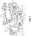
- Figure 1 schematically illustrates a portion of a gas turbine engine 10. Although depicted as a turbofan in the disclosed non-limiting embodiment, it should be appreciated that the concepts described herein are not limited to use with turbofans as the teachings may be applied to other types of turbo machines.
- the gas turbine engine 10 generally includes a compressor section 12 and a turbine section 19 mounted on a rotor shaft 15 to form a spool that rotates about an engine longitudinal axis A.
- the turbine 19 is a high pressure turbine.
- the compressor 12 includes a hub 14 mounted to the rotor shaft 15.
- a discharge outlet 16 expels discharge air D from the compressor 12 to a turbine inlet 20 via passages 18.
- a turbine rotor hub 22 that supports rotor blades 24 is mounted on the shaft 15. The blades 24 receive and expand the discharge air D from the turbine inlet 20.
- Purge air P flow is produced within the compressor section 12, and directed to the turbine section 19 through a series of passages.
- compressor seals 26 and 28 arranged between the hub 14 and engine housing may leak purge air P into cavities 30 and 31. The purge air P then leaks past seal 32 and reaches the turbine 19.
- An on-board injector 44 which, in this disclosed non-limiting embodiment, is a tangential on-board injector (TOBI) delivers discharge air D to a space 40 near the turbine 16 for cooling the turbine rotor hub 22.
- a baffle 43 may be arranged between the passage 18 and the on-board injector 44 to turn the air abruptly to separate debris before communication to the turbine 19.
- the on-board injector 44 is generally parallel to the engine longitudinal axis A.
- a coverplate 36 separates the on-board injector 44 and the turbine rotor hub 22.
- a multiple of coverplate apertures 38 are provided in the coverplate 36 to direct cooling air C from the on-board injector 44 to be directed into the turbine rotor hub 22.
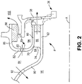
- the on-board injector 44 generally includes a first wall 60, a second wall 62 spaced from the first wall to define an annular inlet 64 about the engine longitudinal axis A, and a multiple of airfoil shapes 66 between the first wall 60 and the second wall 62 to segregate discharge air from the annular inlet 64 (also shown in Figure 3 ).
- the first and second wall 60, 62 are annular walls defined about the engine axis A. It should be appreciated that the on-board injector 44 may be manufactured of separate assembled components or integrally manufactured such as via an additive manufacturing process.
- Each of the multiple of airfoil shapes 66 include a respective bypass aperture 68 each along a radial axis B ( Figure 4 ) transverse to the engine longitudinal axis A and the respective first and second wall 60, 62.
- Each of the multiple of airfoil shapes 66 includes a first sidewall 70 that may be convex and defines a suction side, and a second sidewall 72 that may be concave and define a pressure side. Sidewalls 70, 72 are joined at a leading edge 74 and at an axially spaced trailing edge 76.
- each airfoil trailing edge 76 is spaced chordwise and downstream from the airfoil leading edge 74 to segregate the discharge air from the annular inlet 64 though a cascade exit 80 ( Figure 5 ). That is, the cascade exit 80 is defined by the sidewalls 70, 72 which separate the initially annular flow into the annular inlet 64 such that the pressure side is in a rotational downstream position with respect to the coverplate 36 about the engine longitudinal axis A.
- each trailing edge 76 is arranged about 80 degrees to axial. In another disclosed non-limiting embodiment, each trailing edge 76 is arranged about 10 degrees to circumferential.
- the first wall 60 further includes a radial first wall portion 82 with a multiple of apertures 83 in communication with a cooling air supply cavity 84.
- the radial first wall portion 82 extends into an outer rim portion 86 operable to support a static seal 88.
- the static seal 88 extends radially inward from the outer rim portion 86 to interface with a knife edge 89 that extends from the coverplate 36. That is, the outer rim portion 86, the radial first wall portion 82 and the first wall portion 60 defines a generally U-shape in cross-section.
- the second wall 62 includes an extended portion 90 with a multiple of apertures 92 in communication with the cooling air supply cavity 84.
- the apertures 83, 92 are optional and may facilitate, for example, mass flow distribution between the cooling air supply cavity 84, an outer rim sealing cavity 94, and an inner turbine rotor purge cavity 96.
- the mass flow through aperture 83 is preferably zero.
- the mass flow through aperture 92 is minimized with the combined flow from aperture 92 and the purge mass flow P substantially equal to the mass flow required for purging an outermost rim cavity 100.
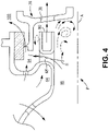
- bypass apertures 68 communicate, or bypass, airflow from the inner turbine rotor purge cavity 96 to the outer rim sealing cavity 94 such that the airflow does not cross the discharge air from the annular inlet 64 that is directed into the coverplate apertures 38.
- the bypass apertures 68 may be circular or otherwise shaped such as teardrop or oval to further accommodate and/or modify airflow therethrough.
- 20-40 bypass apertures 68 each of about 0.25 inches (6.25mm) in diameter are provided.
- This architecture minimizes or avoids the ejector effect of a conventional cascade exit.
- the cascade forms a nozzle that swirls and accelerates the cooling flow to match the rotational velocity of the rotor.
- the increase in momentum of this mass flow can entrain surrounding air, and pull it into the high velocity flow.
- the low momentum purge air P had to cross the plane of the cascade exit.
- the crossing purge flow P both inhibited the flow of the discharge air from the cascade exit and added to the mixing between the cooling flow C and purge flow P, which raised the temperature of the cooling air reaching the rotor, lowering the cooling air overall momentum, and thereby reducing cooling effectiveness.
- the bypass apertures 68 essentially operate as vents through the cascade such that the purge mass flow can pass through the "solid walls" created by the cascade flowpath on-board injector 44, and satisfy the K/E mass flow requirements.
- the crossing flow is greatly reduced, the on-board injector cooling flow is provided to the rotor with less pollution, and a lower overall temperature results.
- the temperature is operational reduced by 4-5%. Lower blade cooling air temperature allows the rotor cooling flow to be reduced for a cycle improvement, a reduction in TSFC, and improved turbine efficiency.
- the on-board injector 44 inlet mass flow at cavity 84 is about equal to the cooling flow C, the purge air P, the mass flow through the multiple of apertures 83 and the mass flow through aperture 92. Further, it may be desired that the mass flow through the multiple of apertures 83 is zero, while the purge air P and the mass flow through aperture 92 pass through the bypass apertures 68.
- the on-board injector 44A is an angled on-board injector (AOBI).
- AOBI angled on-board injector
- the on-board injector 44A is as described above but angled with respect to the engine longitudinal axis A (also shown in Figure 7 ).
- the on-board injector 44B is a radial on-board injector (ROBI).
- ROBI radial on-board injector
- the on-board injector 44B is as described above but generally perpendicular to the engine longitudinal axis A (also shown in Figure 9 ). It should be appreciated that other arrangements will benefit herefrom.
Description
- The present disclosure relates to a gas turbine engine and, more particularly, to Tangential On-Board Injectors.
- Gas turbine engines, such as those that power modem commercial and military aircraft, generally include a compressor section to pressurize an airflow, a combustor section to burn a hydrocarbon fuel in the presence of the pressurized air, and a turbine section to extract energy from the resultant combustion gases. The hot gases expanded within the turbine section produce a gas stream across alternating rows of stationary turbine stator vanes and rotating turbine rotor blades produce power.
Internal secondary flow systems transfer cooling air that bypasses the combustor section to a turbine rotor assembly for subsequent distribution to the interior of the rotor blades through a tangential on-board injector (TOBI). Accelerating the cooling air through a nozzle, and swirling the air with the rotation of the turbine rotor, reduces the temperature of the cooling air as it is injected on board the turbine rotor. - The volume and direction of the cooling air are features of the secondary flow system effectiveness and overall engine performance. The secondary flow system should provide a desired metered amount of cooling air as additional cooling air will penalize efficiency of the engine, while too little cooling air may result in overheating of the rotating turbine disks, blades, and seals Additionally, the secondary flow system directs purge air within the engine to prevent hot gas ingestion in the turbine rim cavities. Typically, rotating Knife Edge (K/E) seals, in conjunction with honeycomb seal lands, are used to control the amount of purge mass flow needed to seal and purge cavities. Other seals such as brush seals and contact seals can be used for this purpose with varying sealing effectiveness; however a certain amount of purge mass flow is required to properly protect the turbine rotor from hot-gas ingestion at the rim cavities. Heat pickup due to passage heat conduction/convection, rotor cooling, and windage losses due to the rotation effects of the disks and rotating seals, increases the temperature of the purge flow as it passes through the engine. It is desirable to use this heated purge air to satisfy the rim cavity mass flow requirement, as its cooling effectiveness has been greatly reduced and no longer has ability to do further rotor/blade cooling.
- The temperature of blade cooling air is negatively affected by the undesirable mixing of the cooling air with the purge air, which is air that flows past the various seals and cavities within the gas turbine engine towards the TOBI. When air exits the TOBI, the flow does not purely flow into the rotor/blade as rotor cavity purge air must flow across the TOBI discharge stream. The crossing flows mix, and pollutes the TOBI flow. The net result is the air flowing to the blade may be relatively hotter and thereby relatively less thermally efficient.
-
- The invention provides a gas turbine engine as claimed in claim 1.
- A further embodiment of the present disclosure includes, wherein the multiple of airfoil shapes include a trailing edge arranged about 80 degrees to an engine axis.
- A further embodiment of any of the foregoing embodiments of the present disclosure includes, wherein the multiple of airfoil shapes include a trailing edge arranged about 10 degrees to circumferential.
- A further embodiment of any of the foregoing embodiments of the present disclosure includes, wherein the multiple of airfoil shapes define a cascade exit to segregate the discharge air.
- A further embodiment of any of the foregoing embodiments of the present disclosure includes, wherein each the multiple of airfoil shapes include a pressure side and a suction side, the pressure side in a rotational downstream position with respect to a coverplate about the engine axis.
- A further embodiment of any of the foregoing embodiments of the present disclosure includes, wherein the first wall includes a first wall portion with a multiple of apertures.
- A further embodiment of any of the foregoing embodiments of the present disclosure includes, an outer rim that extends from the portion.
- A further embodiment of any of the foregoing embodiments of the present disclosure includes, a static seal that extends radially inward from the outer rim that extends from the radial portion.
- A further embodiment of any of the foregoing embodiments of the present disclosure includes a knife edge that extends from the coverplate to seal with the static seal.
- A further embodiment of any of the foregoing embodiments of the present disclosure includes, wherein the outer rim, the radial first wall portion and the first wall define a generally U-shape in cross-section.
- A further embodiment of any of the foregoing embodiments of the present disclosure includes, wherein the coverplate includes a multiple of coverplate apertures to receive the discharge air.
- A further embodiment of any of the foregoing embodiments of the present disclosure includes, wherein the second wall includes an extended portion with a multiple of apertures.
- A further embodiment of any of the foregoing embodiments of the present disclosure includes, wherein the multiple of bypass apertures are circular.
- A further embodiment of any of the foregoing embodiments of the present disclosure includes, wherein the on-board injector is a radial on board injector.
- A further embodiment of any of the foregoing embodiments of the present disclosure includes, wherein the on-board injector is an angled on board injector.
- A further embodiment of any of the foregoing embodiments of the present disclosure includes, wherein the multiple of airfoil shapes define a cascade exit to segregate the discharge air.
- A method of managing purge air within the gas turbine engine is also provided as defined in claim 5.
- A further embodiment of any of the foregoing embodiments of the present disclosure includes, tangentially directing the discharge air.
- The foregoing features and elements may be combined in various combinations without exclusivity, unless expressly indicated otherwise. These features and elements as well as the operation thereof will become more apparent in light of the following description and the accompanying drawings. It should be appreciated, however, the following description and drawings are intended to be exemplary in nature and non-limiting.
- Various features will become apparent to those skilled in the art from the following detailed description of the disclosed non-limiting embodiments. The drawings that accompany the detailed description can be briefly described as follows:
-
Figure 1 is a fragmentary axial cross section of a portion of the turbine section of a gas turbine engine showing a tangential on-board injector (TOBI) nozzle for the distribution of cooling air; -
Figure 2 is an enlarged axial cross section view of a tangential on-board injector (TOBI) used to distribute discharge air for cooling the turbine taken along line 2-2 inFigure 3 ; -
Figure 3 is a partially broken perspective view of the TOBI from an annular inlet perspective; -
Figure 4 is an enlarged axial cross section view of a tangential on-board injector (TOBI) used to distribute discharge air for cooling the turbine taken along line 4-4 inFigure 5 ; -
Figure 5 is a partially broken perspective view of the TOBI from a cascade exit perspective; -
Figure 6 is an enlarged axial cross section view of an angled on-board injector (AOBI) used to distribute discharge air for cooling the turbine; -
Figure 7 is a sectional view of the AOBI taken along line 7-7 inFigure 6 ; -
Figure 8 is an enlarged axial cross section view of a radial on-board injector (ROBI) used to distribute discharge air for cooling the turbine; and -
Figure 9 is a sectional view of the ROBI taken along line 9-9 inFigure 8 . -
Figure 1 schematically illustrates a portion of agas turbine engine 10. Although depicted as a turbofan in the disclosed non-limiting embodiment, it should be appreciated that the concepts described herein are not limited to use with turbofans as the teachings may be applied to other types of turbo machines. - The
gas turbine engine 10 generally includes acompressor section 12 and aturbine section 19 mounted on arotor shaft 15 to form a spool that rotates about an engine longitudinal axis A. In this disclosed non-limiting embodiment, theturbine 19 is a high pressure turbine. Thecompressor 12 includes ahub 14 mounted to therotor shaft 15. Adischarge outlet 16 expels discharge air D from thecompressor 12 to aturbine inlet 20 viapassages 18. Aturbine rotor hub 22 that supportsrotor blades 24 is mounted on theshaft 15. Theblades 24 receive and expand the discharge air D from theturbine inlet 20. - Purge air P flow is produced within the
compressor section 12, and directed to theturbine section 19 through a series of passages. For example,compressor seals hub 14 and engine housing may leak purge air P intocavities seal 32 and reaches theturbine 19. - An on-board injector 44 which, in this disclosed non-limiting embodiment, is a tangential on-board injector (TOBI) delivers discharge air D to a
space 40 near theturbine 16 for cooling theturbine rotor hub 22. A baffle 43 may be arranged between thepassage 18 and the on-board injector 44 to turn the air abruptly to separate debris before communication to theturbine 19. The on-board injector 44 is generally parallel to the engine longitudinal axis A. - A
coverplate 36 separates the on-board injector 44 and theturbine rotor hub 22. A multiple ofcoverplate apertures 38 are provided in thecoverplate 36 to direct cooling air C from the on-board injector 44 to be directed into theturbine rotor hub 22. - With reference to
Figure 2 , the on-board injector 44 generally includes afirst wall 60, asecond wall 62 spaced from the first wall to define anannular inlet 64 about the engine longitudinal axis A, and a multiple of airfoil shapes 66 between thefirst wall 60 and thesecond wall 62 to segregate discharge air from the annular inlet 64 (also shown inFigure 3 ). The first andsecond wall - Each of the multiple of airfoil shapes 66 include a
respective bypass aperture 68 each along a radial axis B (Figure 4 ) transverse to the engine longitudinal axis A and the respective first andsecond wall first sidewall 70 that may be convex and defines a suction side, and asecond sidewall 72 that may be concave and define a pressure side.Sidewalls leading edge 74 and at an axially spaced trailingedge 76. More specifically, eachairfoil trailing edge 76 is spaced chordwise and downstream from theairfoil leading edge 74 to segregate the discharge air from theannular inlet 64 though a cascade exit 80 (Figure 5 ). That is, thecascade exit 80 is defined by thesidewalls annular inlet 64 such that the pressure side is in a rotational downstream position with respect to thecoverplate 36 about the engine longitudinal axis A. - The
sidewalls second wall annular inlet 64 and turn the discharge air in a tangential direction coordinated with a rotational direction of thecoverplate 36 and theturbine rotor hub 22. In one disclosed non-limiting embodiment, each trailingedge 76 is arranged about 80 degrees to axial. In another disclosed non-limiting embodiment, each trailingedge 76 is arranged about 10 degrees to circumferential. - The
first wall 60 further includes a radialfirst wall portion 82 with a multiple ofapertures 83 in communication with a coolingair supply cavity 84. The radialfirst wall portion 82 extends into anouter rim portion 86 operable to support astatic seal 88. Thestatic seal 88 extends radially inward from theouter rim portion 86 to interface with aknife edge 89 that extends from thecoverplate 36. That is, theouter rim portion 86, the radialfirst wall portion 82 and thefirst wall portion 60 defines a generally U-shape in cross-section. - The
second wall 62 includes an extendedportion 90 with a multiple ofapertures 92 in communication with the coolingair supply cavity 84. Theapertures air supply cavity 84, an outerrim sealing cavity 94, and an inner turbinerotor purge cavity 96. The mass flow throughaperture 83 is preferably zero. The mass flow throughaperture 92 is minimized with the combined flow fromaperture 92 and the purge mass flow P substantially equal to the mass flow required for purging anoutermost rim cavity 100. - With reference to
Figure 4 , thebypass apertures 68 communicate, or bypass, airflow from the inner turbinerotor purge cavity 96 to the outerrim sealing cavity 94 such that the airflow does not cross the discharge air from theannular inlet 64 that is directed into thecoverplate apertures 38. The bypass apertures 68 may be circular or otherwise shaped such as teardrop or oval to further accommodate and/or modify airflow therethrough. In one example, 20-40bypass apertures 68 each of about 0.25 inches (6.25mm) in diameter are provided. - This architecture minimizes or avoids the ejector effect of a conventional cascade exit. The cascade forms a nozzle that swirls and accelerates the cooling flow to match the rotational velocity of the rotor. The increase in momentum of this mass flow can entrain surrounding air, and pull it into the high velocity flow. Previously, the low momentum purge air P had to cross the plane of the cascade exit. The crossing purge flow P both inhibited the flow of the discharge air from the cascade exit and added to the mixing between the cooling flow C and purge flow P, which raised the temperature of the cooling air reaching the rotor, lowering the cooling air overall momentum, and thereby reducing cooling effectiveness.
- The bypass apertures 68 essentially operate as vents through the cascade such that the purge mass flow can pass through the "solid walls" created by the cascade flowpath on-board injector 44, and satisfy the K/E mass flow requirements. Thus, the crossing flow is greatly reduced, the on-board injector cooling flow is provided to the rotor with less pollution, and a lower overall temperature results. In one example, the temperature is operational reduced by 4-5%. Lower blade cooling air temperature allows the rotor cooling flow to be reduced for a cycle improvement, a reduction in TSFC, and improved turbine efficiency.
- It should be appreciated that in some cases there will be a contribution from the on-board injector 44 discharge flow to form the purge air P. If the turbine rotor cavity is effectively sealed off from the HPC discharge air, then the on-board injector 44 inlet mass flow at
cavity 84 is about equal to the cooling flow C, the purge air P, the mass flow through the multiple ofapertures 83 and the mass flow throughaperture 92. Further, it may be desired that the mass flow through the multiple ofapertures 83 is zero, while the purge air P and the mass flow throughaperture 92 pass through thebypass apertures 68. - With reference to
Figure 6 , in another disclosed non-limiting embodiment, the on-board injector 44A is an angled on-board injector (AOBI). The on-board injector 44A is as described above but angled with respect to the engine longitudinal axis A (also shown inFigure 7 ). - With reference to
Figure 8 , in another disclosed non-limiting embodiment, the on-board injector 44B is a radial on-board injector (ROBI). The on-board injector 44B is as described above but generally perpendicular to the engine longitudinal axis A (also shown inFigure 9 ). It should be appreciated that other arrangements will benefit herefrom. - Although the different non-limiting embodiments have specific illustrated components, the embodiments of this invention are not limited to those particular combinations. It is possible to use some of the components or features from any of the non-limiting embodiments in combination with features or components from any of the other non-limiting embodiments.
- It should be appreciated that relative positional terms such as "forward," "aft," "upper," "lower," "above," "below," and the like are with reference to the normal operational attitude of the vehicle and should not be considered otherwise limiting.
- It should be appreciated that like reference numerals identify corresponding or similar elements throughout the several drawings. It should also be appreciated that although a particular component arrangement is disclosed in the illustrated embodiment, other arrangements will benefit herefrom.
- Although particular step sequences are shown, described, and claimed, it should be appreciated that steps may be performed in any order, separated or combined unless otherwise indicated and will still benefit from the present disclosure.
- The foregoing description is exemplary rather than defined by the limitations within. Various non-limiting embodiments are disclosed herein, however, one of ordinary skill in the art would recognize that various modifications and variations in light of the above teachings will fall within the scope of the appended claims. It is therefore to be appreciated that within the scope of the appended claims, the disclosure may be practiced other than as specifically described. For that reason the appended claims should be studied to determine true scope and content.
Claims (5)
- A gas turbine engine (10) comprising:a compressor section (12) and a high pressure turbine section (19), mounted on a rotor shaft (15) to form a spool that rotates about an engine longitudinal axis (A), the compressor section (12) including a hub (14) mounted on the rotor shaft (15);a discharge outlet (16) arranged to expel discharge air (D) from the compressor section (12) to a turbine inlet (20) via one or more passage (18);a turbine rotor hub (22) mounted on the shaft (15) in the turbine section (19) and supporting rotor blades (24) of a turbine rotor to receive and expand the discharge air (D) from the turbine inlet (20);the compressor section (12) producing a purge air (P) flow directed to the turbine section (19) through a series of passages;a seal (32) between the compressor section (12) and the turbine section (19) through which purge air (P) leaks;an on-board injector (44) arranged to deliver discharge air (D) from the compressor section (12) into the high pressure turbine section (19), wherein the on-board injector (44) extends into the high pressure turbine section (19) and terminates in the high pressure turbine section at a discharge air outlet (80) of the injector (44);a coverplate (36), in the high pressure turbine section (19), for the turbine rotor defined about the engine longitudinal axis (A), said coverplate (36) including a multiple of coverplate apertures (38); andthe on-board injector (44) having, within the turbine section (19), a multiple of airfoil shapes (66) between a first wall (60) and a second wall (62) to define an annular inlet (64) about the engine longitudinal axis (A), each of said multiple of airfoil shapes (66) including a trailing edge (76) to join said first wall (60) and said second wall (62), said multiple of airfoil shapes (66) operable to segregate and direct High Pressure Compressor HPC discharge air (D) from the annular inlet (64) through the discharge air outlet (80) toward said multiple of coverplate apertures (38), said on-board injector (44) including a multiple of bypass apertures (68) each along a radial axis (B) transverse to the engine longitudinal axis (A), each one of said bypass apertures (68) extending through a respective one of said multiple of airfoil shapes (66), said first wall (60), and said second wall (62) through which purge air (P) in the high pressure turbine section (19) is directed and thus prevented from crossing the flow of discharge air (D) at the discharge air outlet (80).
- The engine (10) as recited in claim 1, wherein said on-board injector (44) is:a radial on board injector; oran angled on board injector.
- The engine (10) as recited in claim 1 or 2, wherein each said multiple of airfoil shapes (66) include a pressure side and a suction side, said pressure side being in a rotational downstream position with respect to a coverplate (36) about said engine axis (A).
- The engine (10) as recited in claim 1, 2 or 3, wherein said multiple of airfoil shapes (66) define a cascade exit to segregate the HPC discharge air (D).
- A method of managing purge air (P) within a gas turbine engine as claimed in any preceding claim, the method comprising the steps of:segregating the High Pressure Compressor HPC discharge air (D) from the annular inlet (64) with the multiple of airfoil shapes (66), and directing said discharge air (D) from the annular inlet through the discharge air outlet (80) into the high pressure turbine section (19) and toward the multiple of coverplate apertures (38); anddirecting the leaked purge air (P) in the high pressure turbine section (19) through the multiple of bypass apertures (68), thus preventing the purge air (P) in the high pressure turbine section from crossing the flow of discharge air (D) at the discharge air outlet (80).
Applications Claiming Priority (1)
| Application Number | Priority Date | Filing Date | Title |
|---|---|---|---|
| US201461973338P | 2014-04-01 | 2014-04-01 |
Publications (3)
| Publication Number | Publication Date |
|---|---|
| EP2942483A1 EP2942483A1 (en) | 2015-11-11 |
| EP2942483B1 EP2942483B1 (en) | 2018-01-03 |
| EP2942483B2 true EP2942483B2 (en) | 2022-09-28 |
Family
ID=52423672
Family Applications (1)
| Application Number | Title | Priority Date | Filing Date |
|---|---|---|---|
| EP15153368.4A Active EP2942483B2 (en) | 2014-04-01 | 2015-01-30 | Vented tangential on-board injector for a gas turbine engine |
Country Status (2)
| Country | Link |
|---|---|
| US (3) | US9945248B2 (en) |
| EP (1) | EP2942483B2 (en) |
Families Citing this family (20)
| Publication number | Priority date | Publication date | Assignee | Title |
|---|---|---|---|---|
| US9435206B2 (en) * | 2012-09-11 | 2016-09-06 | General Electric Company | Flow inducer for a gas turbine system |
| EP2942483B2 (en) * | 2014-04-01 | 2022-09-28 | Raytheon Technologies Corporation | Vented tangential on-board injector for a gas turbine engine |
| US10233840B2 (en) | 2014-04-25 | 2019-03-19 | United Technologies Corporation | Compressor injector apparatus and system |
| EP2980361B1 (en) * | 2014-07-28 | 2018-02-14 | United Technologies Corporation | A cooling system of a stator assembly for a gas turbine engine having a variable cooling flow mechanism and method of operation |
| US20170089213A1 (en) | 2015-09-28 | 2017-03-30 | United Technologies Corporation | Duct with additive manufactured seal |
| US20170292393A1 (en) * | 2016-04-08 | 2017-10-12 | United Technologies Corporation | Tangential on-board injectors for gas turbine engines |
| PL417315A1 (en) * | 2016-05-25 | 2017-12-04 | General Electric Company | Turbine engine with swirl vane |
| US10823184B2 (en) | 2016-07-28 | 2020-11-03 | General Electric Company | Engine with face seal |
| US10787920B2 (en) | 2016-10-12 | 2020-09-29 | General Electric Company | Turbine engine inducer assembly |
| US11578668B2 (en) * | 2017-05-30 | 2023-02-14 | Raytheon Technologies Corporation | Gas turbine engine control based on characteristic of cooled air |
| CN109630209A (en) * | 2018-12-10 | 2019-04-16 | 中国航发四川燃气涡轮研究院 | A kind of band is prewhirled the turbine disk chamber seal structure of bleed |
| US11105212B2 (en) | 2019-01-29 | 2021-08-31 | Honeywell International Inc. | Gas turbine engines including tangential on-board injectors and methods for manufacturing the same |
| CN110206591A (en) * | 2019-06-04 | 2019-09-06 | 中国船舶重工集团公司第七0三研究所 | A kind of groove-type cooling air guiding device for turbine rotor blade gas supply |
| US11808178B2 (en) | 2019-08-05 | 2023-11-07 | Rtx Corporation | Tangential onboard injector inlet extender |
| US11421597B2 (en) | 2019-10-18 | 2022-08-23 | Pratt & Whitney Canada Corp. | Tangential on-board injector (TOBI) assembly |
| IT202000013609A1 (en) | 2020-06-08 | 2021-12-08 | Ge Avio Srl | COMPONENT OF A TURBINE ENGINE WITH AN ASSEMBLY OF DEFLECTORS |
| US11371700B2 (en) | 2020-07-15 | 2022-06-28 | Raytheon Technologies Corporation | Deflector for conduit inlet within a combustor section plenum |
| US11598265B2 (en) * | 2021-02-03 | 2023-03-07 | Pratt & Whitney Canada Corp. | Tangential on-board injector |
| US11859550B2 (en) * | 2021-04-01 | 2024-01-02 | General Electric Company | Compound angle accelerator |
| US20240026820A1 (en) * | 2022-07-22 | 2024-01-25 | General Electric Company | Sump arrangement for a gas turbine engine |
Citations (3)
| Publication number | Priority date | Publication date | Assignee | Title |
|---|---|---|---|---|
| US5245821A (en) † | 1991-10-21 | 1993-09-21 | General Electric Company | Stator to rotor flow inducer |
| US5402636A (en) † | 1993-12-06 | 1995-04-04 | United Technologies Corporation | Anti-contamination thrust balancing system for gas turbine engines |
| WO2003040524A1 (en) † | 2001-11-08 | 2003-05-15 | Snecma Moteurs | Gas turbine stator |
Family Cites Families (25)
| Publication number | Priority date | Publication date | Assignee | Title |
|---|---|---|---|---|
| US4526511A (en) | 1982-11-01 | 1985-07-02 | United Technologies Corporation | Attachment for TOBI |
| US4822244A (en) * | 1987-10-15 | 1989-04-18 | United Technologies Corporation | Tobi |
| US4872810A (en) | 1988-12-14 | 1989-10-10 | United Technologies Corporation | Turbine rotor retention system |
| DE4031936A1 (en) | 1990-10-09 | 1992-04-16 | Klein Schanzlin & Becker Ag | CONTROL DEVICE |
| FR2685936A1 (en) | 1992-01-08 | 1993-07-09 | Snecma | DEVICE FOR CONTROLLING THE GAMES OF A TURBOMACHINE COMPRESSOR HOUSING. |
| US5316437A (en) | 1993-02-19 | 1994-05-31 | General Electric Company | Gas turbine engine structural frame assembly having a thermally actuated valve for modulating a flow of hot gases through the frame hub |
| US5639210A (en) | 1995-10-23 | 1997-06-17 | United Technologies Corporation | Rotor blade outer tip seal apparatus |
| FR2743844B1 (en) * | 1996-01-18 | 1998-02-20 | Snecma | DEVICE FOR COOLING A TURBINE DISC |
| FR2744761B1 (en) | 1996-02-08 | 1998-03-13 | Snecma | LABYRINTH DISC WITH INCORPORATED STIFFENER FOR TURBOMACHINE ROTOR |
| US6227801B1 (en) | 1999-04-27 | 2001-05-08 | Pratt & Whitney Canada Corp. | Turbine engine having improved high pressure turbine cooling |
| US6183193B1 (en) | 1999-05-21 | 2001-02-06 | Pratt & Whitney Canada Corp. | Cast on-board injection nozzle with adjustable flow area |
| US6382905B1 (en) | 2000-04-28 | 2002-05-07 | General Electric Company | Fan casing liner support |
| US6722138B2 (en) | 2000-12-13 | 2004-04-20 | United Technologies Corporation | Vane platform trailing edge cooling |
| US6773225B2 (en) | 2002-05-30 | 2004-08-10 | Mitsubishi Heavy Industries, Ltd. | Gas turbine and method of bleeding gas therefrom |
| FR2840351B1 (en) * | 2002-05-30 | 2005-12-16 | Snecma Moteurs | COOLING THE FLASK BEFORE A HIGH PRESSURE TURBINE BY A DOUBLE INJECTOR SYSTEM BOTTOM BOTTOM |
| US6877952B2 (en) | 2002-09-09 | 2005-04-12 | Florida Turbine Technologies, Inc | Passive clearance control |
| US6837676B2 (en) | 2002-09-11 | 2005-01-04 | Mitsubishi Heavy Industries, Ltd. | Gas turbine |
| US7094029B2 (en) | 2003-05-06 | 2006-08-22 | General Electric Company | Methods and apparatus for controlling gas turbine engine rotor tip clearances |
| US8011883B2 (en) | 2004-12-29 | 2011-09-06 | United Technologies Corporation | Gas turbine engine blade tip clearance apparatus and method |
| FR2904038A1 (en) * | 2006-07-19 | 2008-01-25 | Snecma Sa | Centrifugal compressor impeller downstream face cooling system for aircraft turbomachine e.g. turbojet and jet prop engines, has cylindrical passage and sheet guiding drawn ventilating air till neighborhood of downstream face of impeller |
| US8381533B2 (en) | 2009-04-30 | 2013-02-26 | Honeywell International Inc. | Direct transfer axial tangential onboard injector system (TOBI) with self-supporting seal plate |
| US8342798B2 (en) | 2009-07-28 | 2013-01-01 | General Electric Company | System and method for clearance control in a rotary machine |
| US9228497B2 (en) * | 2010-12-30 | 2016-01-05 | Rolls-Royce Corporation | Gas turbine engine with secondary air flow circuit |
| US8790067B2 (en) | 2011-04-27 | 2014-07-29 | United Technologies Corporation | Blade clearance control using high-CTE and low-CTE ring members |
| EP2942483B2 (en) * | 2014-04-01 | 2022-09-28 | Raytheon Technologies Corporation | Vented tangential on-board injector for a gas turbine engine |
-
2015
- 2015-01-30 EP EP15153368.4A patent/EP2942483B2/en active Active
- 2015-01-30 US US14/609,926 patent/US9945248B2/en active Active
-
2018
- 2018-03-06 US US15/913,269 patent/US10697321B2/en active Active
-
2020
- 2020-06-10 US US16/897,433 patent/US10920611B2/en active Active
Patent Citations (3)
| Publication number | Priority date | Publication date | Assignee | Title |
|---|---|---|---|---|
| US5245821A (en) † | 1991-10-21 | 1993-09-21 | General Electric Company | Stator to rotor flow inducer |
| US5402636A (en) † | 1993-12-06 | 1995-04-04 | United Technologies Corporation | Anti-contamination thrust balancing system for gas turbine engines |
| WO2003040524A1 (en) † | 2001-11-08 | 2003-05-15 | Snecma Moteurs | Gas turbine stator |
Also Published As
| Publication number | Publication date |
|---|---|
| US10920611B2 (en) | 2021-02-16 |
| US10697321B2 (en) | 2020-06-30 |
| US20150275690A1 (en) | 2015-10-01 |
| US9945248B2 (en) | 2018-04-17 |
| US20200362726A1 (en) | 2020-11-19 |
| EP2942483B1 (en) | 2018-01-03 |
| EP2942483A1 (en) | 2015-11-11 |
| US20180195410A1 (en) | 2018-07-12 |
Similar Documents
| Publication | Publication Date | Title |
|---|---|---|
| US10920611B2 (en) | Vented tangential on-board injector for a gas turbine engine | |
| US20090110561A1 (en) | Turbine engine components, turbine engine assemblies, and methods of manufacturing turbine engine components | |
| US8920128B2 (en) | Gas turbine engine cooling systems having hub-bleed impellers and methods for the production thereof | |
| EP3090163B1 (en) | Compressor rim thermal management | |
| EP2325438B1 (en) | Seal plates for directing airflow through a turbine section of an engine and turbine sections | |
| CN110300838B (en) | Thermal structure for outer diameter mounted turbine blades | |
| EP2855884A1 (en) | High pressure turbine coolant supply system | |
| EP3640432B1 (en) | Turbine shroud assemblies for gas turbine engines | |
| CN108868898A (en) | The device and method of airfoil for cooling turbine engines | |
| EP3012405B1 (en) | Gas turbine engine with coolant flow redirection component | |
| EP2551458A2 (en) | Blade Cooling and Sealing System | |
| JP2017141832A (en) | Surface contouring | |
| JP2015092076A (en) | Method and system for providing cooling for turbine assembly | |
| EP2798175A2 (en) | Gas turbine engine and turbine blade | |
| CN108868897A (en) | The insertion piece of turbine engine airfoil part | |
| JP2006009797A (en) | Air foil insert having spline-machined end part | |
| EP3450692B1 (en) | Seal assembly for the interface between combustor and vane | |
| EP3190261A1 (en) | Stator rim structure for a turbine engine | |
| EP3450693B1 (en) | Seal assembly for the interface between combustor and vane | |
| CN107084002B (en) | Turbine assembly and method of manufacture | |
| EP3159503B1 (en) | Compressor bleeding arrangement for a gas turbine and method of manufacturing a compressor section for a gas turbine | |
| CN110242617B (en) | Compressor rotor cooling apparatus | |
| EP3290637B1 (en) | Tandem rotor blades with cooling features | |
| CN107762563A (en) | With polycolporate engine component | |
| CN114251132A (en) | Gas turbine engine rotor blade with metallic structural member and composite fairing |
Legal Events
| Date | Code | Title | Description |
|---|---|---|---|
| PUAI | Public reference made under article 153(3) epc to a published international application that has entered the european phase |
Free format text: ORIGINAL CODE: 0009012 |
|
| AK | Designated contracting states |
Kind code of ref document: A1 Designated state(s): AL AT BE BG CH CY CZ DE DK EE ES FI FR GB GR HR HU IE IS IT LI LT LU LV MC MK MT NL NO PL PT RO RS SE SI SK SM TR |
|
| AX | Request for extension of the european patent |
Extension state: BA ME |
|
| 17P | Request for examination filed |
Effective date: 20160510 |
|
| RBV | Designated contracting states (corrected) |
Designated state(s): AL AT BE BG CH CY CZ DE DK EE ES FI FR GB GR HR HU IE IS IT LI LT LU LV MC MK MT NL NO PL PT RO RS SE SI SK SM TR |
|
| RAP1 | Party data changed (applicant data changed or rights of an application transferred) |
Owner name: UNITED TECHNOLOGIES CORPORATION |
|
| REG | Reference to a national code |
Ref country code: DE Ref legal event code: R079 Ref document number: 602015007071 Country of ref document: DE Free format text: PREVIOUS MAIN CLASS: F01D0005080000 Ipc: F01D0001020000 |
|
| RIC1 | Information provided on ipc code assigned before grant |
Ipc: F01D 11/00 20060101ALI20170228BHEP Ipc: F02C 7/18 20060101ALI20170228BHEP Ipc: F01D 1/02 20060101AFI20170228BHEP Ipc: F01D 5/08 20060101ALI20170228BHEP Ipc: F01D 11/02 20060101ALI20170228BHEP Ipc: F01D 25/12 20060101ALI20170228BHEP |
|
| GRAP | Despatch of communication of intention to grant a patent |
Free format text: ORIGINAL CODE: EPIDOSNIGR1 |
|
| STAA | Information on the status of an ep patent application or granted ep patent |
Free format text: STATUS: GRANT OF PATENT IS INTENDED |
|
| INTG | Intention to grant announced |
Effective date: 20170717 |
|
| RIN1 | Information on inventor provided before grant (corrected) |
Inventor name: MCCAFFREY, MICHAEL G. |
|
| GRAS | Grant fee paid |
Free format text: ORIGINAL CODE: EPIDOSNIGR3 |
|
| GRAA | (expected) grant |
Free format text: ORIGINAL CODE: 0009210 |
|
| STAA | Information on the status of an ep patent application or granted ep patent |
Free format text: STATUS: THE PATENT HAS BEEN GRANTED |
|
| AK | Designated contracting states |
Kind code of ref document: B1 Designated state(s): AL AT BE BG CH CY CZ DE DK EE ES FI FR GB GR HR HU IE IS IT LI LT LU LV MC MK MT NL NO PL PT RO RS SE SI SK SM TR |
|
| REG | Reference to a national code |
Ref country code: GB Ref legal event code: FG4D |
|
| REG | Reference to a national code |
Ref country code: CH Ref legal event code: EP Ref country code: AT Ref legal event code: REF Ref document number: 960456 Country of ref document: AT Kind code of ref document: T Effective date: 20180115 |
|
| REG | Reference to a national code |
Ref country code: IE Ref legal event code: FG4D |
|
| REG | Reference to a national code |
Ref country code: DE Ref legal event code: R096 Ref document number: 602015007071 Country of ref document: DE |
|
| REG | Reference to a national code |
Ref country code: FR Ref legal event code: PLFP Year of fee payment: 4 |
|
| REG | Reference to a national code |
Ref country code: NL Ref legal event code: MP Effective date: 20180103 |
|
| REG | Reference to a national code |
Ref country code: LT Ref legal event code: MG4D |
|
| REG | Reference to a national code |
Ref country code: AT Ref legal event code: MK05 Ref document number: 960456 Country of ref document: AT Kind code of ref document: T Effective date: 20180103 |
|
| PG25 | Lapsed in a contracting state [announced via postgrant information from national office to epo] |
Ref country code: NL Free format text: LAPSE BECAUSE OF FAILURE TO SUBMIT A TRANSLATION OF THE DESCRIPTION OR TO PAY THE FEE WITHIN THE PRESCRIBED TIME-LIMIT Effective date: 20180103 |
|
| PG25 | Lapsed in a contracting state [announced via postgrant information from national office to epo] |
Ref country code: ES Free format text: LAPSE BECAUSE OF FAILURE TO SUBMIT A TRANSLATION OF THE DESCRIPTION OR TO PAY THE FEE WITHIN THE PRESCRIBED TIME-LIMIT Effective date: 20180103 Ref country code: CY Free format text: LAPSE BECAUSE OF FAILURE TO SUBMIT A TRANSLATION OF THE DESCRIPTION OR TO PAY THE FEE WITHIN THE PRESCRIBED TIME-LIMIT Effective date: 20180103 Ref country code: FI Free format text: LAPSE BECAUSE OF FAILURE TO SUBMIT A TRANSLATION OF THE DESCRIPTION OR TO PAY THE FEE WITHIN THE PRESCRIBED TIME-LIMIT Effective date: 20180103 Ref country code: LT Free format text: LAPSE BECAUSE OF FAILURE TO SUBMIT A TRANSLATION OF THE DESCRIPTION OR TO PAY THE FEE WITHIN THE PRESCRIBED TIME-LIMIT Effective date: 20180103 Ref country code: HR Free format text: LAPSE BECAUSE OF FAILURE TO SUBMIT A TRANSLATION OF THE DESCRIPTION OR TO PAY THE FEE WITHIN THE PRESCRIBED TIME-LIMIT Effective date: 20180103 Ref country code: NO Free format text: LAPSE BECAUSE OF FAILURE TO SUBMIT A TRANSLATION OF THE DESCRIPTION OR TO PAY THE FEE WITHIN THE PRESCRIBED TIME-LIMIT Effective date: 20180403 |
|
| PG25 | Lapsed in a contracting state [announced via postgrant information from national office to epo] |
Ref country code: AT Free format text: LAPSE BECAUSE OF FAILURE TO SUBMIT A TRANSLATION OF THE DESCRIPTION OR TO PAY THE FEE WITHIN THE PRESCRIBED TIME-LIMIT Effective date: 20180103 Ref country code: PL Free format text: LAPSE BECAUSE OF FAILURE TO SUBMIT A TRANSLATION OF THE DESCRIPTION OR TO PAY THE FEE WITHIN THE PRESCRIBED TIME-LIMIT Effective date: 20180103 Ref country code: RS Free format text: LAPSE BECAUSE OF FAILURE TO SUBMIT A TRANSLATION OF THE DESCRIPTION OR TO PAY THE FEE WITHIN THE PRESCRIBED TIME-LIMIT Effective date: 20180103 Ref country code: BG Free format text: LAPSE BECAUSE OF FAILURE TO SUBMIT A TRANSLATION OF THE DESCRIPTION OR TO PAY THE FEE WITHIN THE PRESCRIBED TIME-LIMIT Effective date: 20180403 Ref country code: LV Free format text: LAPSE BECAUSE OF FAILURE TO SUBMIT A TRANSLATION OF THE DESCRIPTION OR TO PAY THE FEE WITHIN THE PRESCRIBED TIME-LIMIT Effective date: 20180103 Ref country code: SE Free format text: LAPSE BECAUSE OF FAILURE TO SUBMIT A TRANSLATION OF THE DESCRIPTION OR TO PAY THE FEE WITHIN THE PRESCRIBED TIME-LIMIT Effective date: 20180103 Ref country code: GR Free format text: LAPSE BECAUSE OF FAILURE TO SUBMIT A TRANSLATION OF THE DESCRIPTION OR TO PAY THE FEE WITHIN THE PRESCRIBED TIME-LIMIT Effective date: 20180404 Ref country code: IS Free format text: LAPSE BECAUSE OF FAILURE TO SUBMIT A TRANSLATION OF THE DESCRIPTION OR TO PAY THE FEE WITHIN THE PRESCRIBED TIME-LIMIT Effective date: 20180503 |
|
| REG | Reference to a national code |
Ref country code: CH Ref legal event code: PL |
|
| REG | Reference to a national code |
Ref country code: DE Ref legal event code: R026 Ref document number: 602015007071 Country of ref document: DE |
|
| PLBI | Opposition filed |
Free format text: ORIGINAL CODE: 0009260 |
|
| PLAX | Notice of opposition and request to file observation + time limit sent |
Free format text: ORIGINAL CODE: EPIDOSNOBS2 |
|
| PG25 | Lapsed in a contracting state [announced via postgrant information from national office to epo] |
Ref country code: IT Free format text: LAPSE BECAUSE OF FAILURE TO SUBMIT A TRANSLATION OF THE DESCRIPTION OR TO PAY THE FEE WITHIN THE PRESCRIBED TIME-LIMIT Effective date: 20180103 Ref country code: RO Free format text: LAPSE BECAUSE OF FAILURE TO SUBMIT A TRANSLATION OF THE DESCRIPTION OR TO PAY THE FEE WITHIN THE PRESCRIBED TIME-LIMIT Effective date: 20180103 Ref country code: MC Free format text: LAPSE BECAUSE OF FAILURE TO SUBMIT A TRANSLATION OF THE DESCRIPTION OR TO PAY THE FEE WITHIN THE PRESCRIBED TIME-LIMIT Effective date: 20180103 Ref country code: AL Free format text: LAPSE BECAUSE OF FAILURE TO SUBMIT A TRANSLATION OF THE DESCRIPTION OR TO PAY THE FEE WITHIN THE PRESCRIBED TIME-LIMIT Effective date: 20180103 Ref country code: LU Free format text: LAPSE BECAUSE OF NON-PAYMENT OF DUE FEES Effective date: 20180130 Ref country code: EE Free format text: LAPSE BECAUSE OF FAILURE TO SUBMIT A TRANSLATION OF THE DESCRIPTION OR TO PAY THE FEE WITHIN THE PRESCRIBED TIME-LIMIT Effective date: 20180103 |
|
| REG | Reference to a national code |
Ref country code: IE Ref legal event code: MM4A |
|
| 26 | Opposition filed |
Opponent name: SAFRAN AIRCRAFT ENGINES Effective date: 20181002 |
|
| REG | Reference to a national code |
Ref country code: BE Ref legal event code: MM Effective date: 20180131 |
|
| PG25 | Lapsed in a contracting state [announced via postgrant information from national office to epo] |
Ref country code: DK Free format text: LAPSE BECAUSE OF FAILURE TO SUBMIT A TRANSLATION OF THE DESCRIPTION OR TO PAY THE FEE WITHIN THE PRESCRIBED TIME-LIMIT Effective date: 20180103 Ref country code: CH Free format text: LAPSE BECAUSE OF NON-PAYMENT OF DUE FEES Effective date: 20180131 Ref country code: BE Free format text: LAPSE BECAUSE OF NON-PAYMENT OF DUE FEES Effective date: 20180131 Ref country code: SM Free format text: LAPSE BECAUSE OF FAILURE TO SUBMIT A TRANSLATION OF THE DESCRIPTION OR TO PAY THE FEE WITHIN THE PRESCRIBED TIME-LIMIT Effective date: 20180103 Ref country code: LI Free format text: LAPSE BECAUSE OF NON-PAYMENT OF DUE FEES Effective date: 20180131 Ref country code: CZ Free format text: LAPSE BECAUSE OF FAILURE TO SUBMIT A TRANSLATION OF THE DESCRIPTION OR TO PAY THE FEE WITHIN THE PRESCRIBED TIME-LIMIT Effective date: 20180103 Ref country code: SK Free format text: LAPSE BECAUSE OF FAILURE TO SUBMIT A TRANSLATION OF THE DESCRIPTION OR TO PAY THE FEE WITHIN THE PRESCRIBED TIME-LIMIT Effective date: 20180103 |
|
| PG25 | Lapsed in a contracting state [announced via postgrant information from national office to epo] |
Ref country code: IE Free format text: LAPSE BECAUSE OF NON-PAYMENT OF DUE FEES Effective date: 20180130 |
|
| PG25 | Lapsed in a contracting state [announced via postgrant information from national office to epo] |
Ref country code: SI Free format text: LAPSE BECAUSE OF FAILURE TO SUBMIT A TRANSLATION OF THE DESCRIPTION OR TO PAY THE FEE WITHIN THE PRESCRIBED TIME-LIMIT Effective date: 20180103 |
|
| PLBB | Reply of patent proprietor to notice(s) of opposition received |
Free format text: ORIGINAL CODE: EPIDOSNOBS3 |
|
| PG25 | Lapsed in a contracting state [announced via postgrant information from national office to epo] |
Ref country code: MT Free format text: LAPSE BECAUSE OF NON-PAYMENT OF DUE FEES Effective date: 20180130 |
|
| PG25 | Lapsed in a contracting state [announced via postgrant information from national office to epo] |
Ref country code: TR Free format text: LAPSE BECAUSE OF FAILURE TO SUBMIT A TRANSLATION OF THE DESCRIPTION OR TO PAY THE FEE WITHIN THE PRESCRIBED TIME-LIMIT Effective date: 20180103 |
|
| PG25 | Lapsed in a contracting state [announced via postgrant information from national office to epo] |
Ref country code: PT Free format text: LAPSE BECAUSE OF FAILURE TO SUBMIT A TRANSLATION OF THE DESCRIPTION OR TO PAY THE FEE WITHIN THE PRESCRIBED TIME-LIMIT Effective date: 20180103 |
|
| PG25 | Lapsed in a contracting state [announced via postgrant information from national office to epo] |
Ref country code: HU Free format text: LAPSE BECAUSE OF FAILURE TO SUBMIT A TRANSLATION OF THE DESCRIPTION OR TO PAY THE FEE WITHIN THE PRESCRIBED TIME-LIMIT; INVALID AB INITIO Effective date: 20150130 Ref country code: MK Free format text: LAPSE BECAUSE OF NON-PAYMENT OF DUE FEES Effective date: 20180103 |
|
| RAP2 | Party data changed (patent owner data changed or rights of a patent transferred) |
Owner name: RAYTHEON TECHNOLOGIES CORPORATION |
|
| PUAH | Patent maintained in amended form |
Free format text: ORIGINAL CODE: 0009272 |
|
| STAA | Information on the status of an ep patent application or granted ep patent |
Free format text: STATUS: PATENT MAINTAINED AS AMENDED |
|
| REG | Reference to a national code |
Ref country code: DE Ref legal event code: R081 Ref document number: 602015007071 Country of ref document: DE Owner name: RAYTHEON TECHNOLOGIES CORPORATION (N.D.GES.D.S, US Free format text: FORMER OWNER: UNITED TECHNOLOGIES CORPORATION, FARMINGTON, CONN., US |
|
| 27A | Patent maintained in amended form |
Effective date: 20220928 |
|
| AK | Designated contracting states |
Kind code of ref document: B2 Designated state(s): AL AT BE BG CH CY CZ DE DK EE ES FI FR GB GR HR HU IE IS IT LI LT LU LV MC MK MT NL NO PL PT RO RS SE SI SK SM TR |
|
| REG | Reference to a national code |
Ref country code: DE Ref legal event code: R102 Ref document number: 602015007071 Country of ref document: DE |
|
| PGFP | Annual fee paid to national office [announced via postgrant information from national office to epo] |
Ref country code: DE Payment date: 20221220 Year of fee payment: 9 |
|
| P01 | Opt-out of the competence of the unified patent court (upc) registered |
Effective date: 20230520 |
|
| PGFP | Annual fee paid to national office [announced via postgrant information from national office to epo] |
Ref country code: GB Payment date: 20231219 Year of fee payment: 10 |
|
| PGFP | Annual fee paid to national office [announced via postgrant information from national office to epo] |
Ref country code: FR Payment date: 20231219 Year of fee payment: 10 |