EP3464738B1 - Sanitary insertion unit - Google Patents
Sanitary insertion unit Download PDFInfo
- Publication number
- EP3464738B1 EP3464738B1 EP17719483.4A EP17719483A EP3464738B1 EP 3464738 B1 EP3464738 B1 EP 3464738B1 EP 17719483 A EP17719483 A EP 17719483A EP 3464738 B1 EP3464738 B1 EP 3464738B1
- Authority
- EP
- European Patent Office
- Prior art keywords
- unit according
- damper
- piston
- insert unit
- housing
- Prior art date
- Legal status (The legal status is an assumption and is not a legal conclusion. Google has not performed a legal analysis and makes no representation as to the accuracy of the status listed.)
- Active
Links
Images


Classifications
-
- E—FIXED CONSTRUCTIONS
- E03—WATER SUPPLY; SEWERAGE
- E03C—DOMESTIC PLUMBING INSTALLATIONS FOR FRESH WATER OR WASTE WATER; SINKS
- E03C1/00—Domestic plumbing installations for fresh water or waste water; Sinks
- E03C1/02—Plumbing installations for fresh water
- E03C1/10—Devices for preventing contamination of drinking-water pipes, e.g. means for aerating self-closing flushing valves
- E03C1/104—Devices for preventing contamination of drinking-water pipes, e.g. means for aerating self-closing flushing valves using a single check valve
-
- E—FIXED CONSTRUCTIONS
- E03—WATER SUPPLY; SEWERAGE
- E03C—DOMESTIC PLUMBING INSTALLATIONS FOR FRESH WATER OR WASTE WATER; SINKS
- E03C1/00—Domestic plumbing installations for fresh water or waste water; Sinks
- E03C1/02—Plumbing installations for fresh water
- E03C1/08—Jet regulators or jet guides, e.g. anti-splash devices
- E03C1/084—Jet regulators with aerating means
-
- F—MECHANICAL ENGINEERING; LIGHTING; HEATING; WEAPONS; BLASTING
- F16—ENGINEERING ELEMENTS AND UNITS; GENERAL MEASURES FOR PRODUCING AND MAINTAINING EFFECTIVE FUNCTIONING OF MACHINES OR INSTALLATIONS; THERMAL INSULATION IN GENERAL
- F16K—VALVES; TAPS; COCKS; ACTUATING-FLOATS; DEVICES FOR VENTING OR AERATING
- F16K17/00—Safety valves; Equalising valves, e.g. pressure relief valves
- F16K17/02—Safety valves; Equalising valves, e.g. pressure relief valves opening on surplus pressure on one side; closing on insufficient pressure on one side
- F16K17/04—Safety valves; Equalising valves, e.g. pressure relief valves opening on surplus pressure on one side; closing on insufficient pressure on one side spring-loaded
- F16K17/0433—Safety valves; Equalising valves, e.g. pressure relief valves opening on surplus pressure on one side; closing on insufficient pressure on one side spring-loaded with vibration preventing means
-
- F—MECHANICAL ENGINEERING; LIGHTING; HEATING; WEAPONS; BLASTING
- F16—ENGINEERING ELEMENTS AND UNITS; GENERAL MEASURES FOR PRODUCING AND MAINTAINING EFFECTIVE FUNCTIONING OF MACHINES OR INSTALLATIONS; THERMAL INSULATION IN GENERAL
- F16K—VALVES; TAPS; COCKS; ACTUATING-FLOATS; DEVICES FOR VENTING OR AERATING
- F16K47/00—Means in valves for absorbing fluid energy
- F16K47/02—Means in valves for absorbing fluid energy for preventing water-hammer or noise
- F16K47/023—Means in valves for absorbing fluid energy for preventing water-hammer or noise for preventing water-hammer, e.g. damping of the valve movement
Landscapes
- Life Sciences & Earth Sciences (AREA)
- Engineering & Computer Science (AREA)
- Hydrology & Water Resources (AREA)
- Public Health (AREA)
- Water Supply & Treatment (AREA)
- Health & Medical Sciences (AREA)
- Fluid-Damping Devices (AREA)
- Details Of Valves (AREA)
- Bidet-Like Cleaning Device And Other Flush Toilet Accessories (AREA)
- Domestic Plumbing Installations (AREA)
- Lift Valve (AREA)
- Multiple-Way Valves (AREA)
- Vibration Prevention Devices (AREA)
- Check Valves (AREA)
Description
Die Erfindung betrifft eine sanitäre Einsetzeinheit mit einem Einsetzgehäuse, in welchem Einsetzgehäuse ein Ventil mit einem Ventilkolben vorgesehen ist, welcher Ventilkolben im Einsetzgehäuse verschieblich geführt und von einer Ruhestellung unter dem Druck des anströmenden Wassers gegen die Rückstellkraft wenigstens eines Rückstellelements bewegbar ist, wobei die Einsetzeinheit zumindest einen Bewegungsdämpfer aufweist, welcher die Bewegung des Ventilkolbens von der Ruhestellung in die Offenposition dämpft oder bremst.The invention relates to a sanitary insert unit with an insert housing, in which the insert housing a valve with a valve piston is provided, which valve piston is displaceably guided in the insert housing and can be moved from a rest position under the pressure of the incoming water against the restoring force of at least one restoring element, the insert unit at least has a movement damper which dampens or brakes the movement of the valve piston from the rest position to the open position.
Die Erfindung befasst sich auch mit der Verwendung einer solchen sanitären Einsetzeinheit.The invention is also concerned with the use of such a sanitary insert unit.
Sanitäre Einsetzeinheiten sind bereits in unterschiedlichen Ausführungen für verschiedene Anwendungen bekannt. So hat man bereits Einsetzeinheiten geschaffen, die als Rückflussverhinderer dienen, um einen entgegen der Durchströmrichtung rückfließenden, eventuell mit Schmutzstoffen kontaminierten Wasserfluss zurück ins Leitungsnetz zu verhindern. Diese als Rückflussverhinderer ausgebildeten Einsetzeinheiten weisen ein zwischen zwei Leitungsabschnitten montierbares Einsetzgehäuse auf, in dem ein Ventil mit einem Ventilkolben vorgesehen ist. Dieser Ventilkolben ist im Einsetzgehäuse verschieblich geführt und von einer Ruhestellung, während der kein Wasser durch das Leitungsnetz strömt, unter dem Druck des nach Öffnen der Armatur anströmenden Wassers gegen die Rückstellkraft wenigstens eines Rückstellelements derart bewegbar, dass das Wasser in der üblichen Durchströmrichtung hindurchfließen kann.
Aus der
From the
Viele Auslaufarmaturen sind als Einhebelarmaturen ausgebildet, bei denen ein Bedienungshebel zum Öffnen und Schließen des Wasserstromes verschwenkt und zum Mischen von Warm- und Kaltwasser gedreht werden kann. Insbesondere auch bei solchen Auslaufarmaturen besteht häufig das Problem, dass die Auslaufarmatur, vielleicht auch unbeabsichtigt, derart rasch geöffnet wird, dass ein starker Wasserschwall im Waschbecken hart auftrifft, der dort unkontrolliert verspritzt und auch den Anwender selbst treffen kann.Many outlet fittings are designed as single-lever fittings in which an operating lever can be pivoted to open and close the water flow and rotated to mix hot and cold water. In particular with such outlet fittings there is often the problem that the outlet fitting is opened, perhaps unintentionally, so quickly that a strong surge of water in the wash basin hits hard, which splashes uncontrollably and can also hit the user himself.
Es besteht daher insbesondere die Aufgabe, eine sanitäre Einsetzeinheit der eingangs erwähnten Art zu schaffen, die auch bei einem schlagartigen Öffnen der Wasserleitung einen sanft anschwellenden Wasserstrom erzeugt.There is therefore, in particular, the task of creating a sanitary insert unit of the type mentioned at the outset which generates a gently swelling water flow even when the water pipe is suddenly opened.
Die erfindungsgemäße Lösung dieser Aufgabe besteht bei der sanitären Einsetzeinheit der eingangs erwähnten Art darin, dass der zumindest eine Bewegungsdämpfer als hydraulischer Dämpfer ausgestaltet ist, der ein Dämpfergehäuse hat, in welchem Dämpfergehäuse ein Dämpferkolben verschieblich geführt ist, wobei der Dämpferkolben während einer Schiebebewegung von der Ruhestellung in die Offenposition Öl oder dergleichen zähflüssiges Fluid von der einen Seite des Dämpferkolbens durch zumindest einen Verbindungskanal auf die andere Seite des Dämpferkolbens verdrängt.The inventive solution to this problem consists in the sanitary insert unit of the type mentioned in that the at least one movement damper is designed as a hydraulic damper, which has a damper housing in which a damper piston is displaceably guided, the damper piston during a sliding movement from the rest position in the open position oil or similar viscous fluid is displaced from one side of the damper piston through at least one connecting channel to the other side of the damper piston.
Die erfindungsgemäße Einsetzeinheit weist ein Einsetzgehäuse auf, das im Wasserauslauf einer sanitären Auslaufarmatur montiert oder zwischen zwei Leitungsabschnitten einer Wasserleitung, beispielsweise in einem Eck- oder Anschlussventil, eingesetzt werden kann. Dabei soll die Einsetzeinheit bei einem schlagartigen Öffnen eines in der Wasserleitung vorgesehenen Auslaufventils einen sanft anschwellenden Wasserstrom erzeugen. Im Einsetzgehäuse der Einsetzeinheit ist dazu ein Ventil mit einem Ventilkolben vorgesehen, der von einer Ruhestellung unter dem Druck des gegen die Einsetzeinheit und dessen Ventilkolben anströmenden Wassers gegen die Rückstellkraft wenigstens eines Rückstellelements bewegbar ist. Dabei kann die Ruhestellung als Schließstellung des Ventils ausgestaltet oder als eine Durchflussposition ausgebildet sein, die gegenüber der Offenstellung einen reduzierten Durchflussquerschnitt bietet. Das Dämpfergehäuse, das im Einsetzgehäuse angeordnet ist und zumindest in der Offenstellung von dem durch das Einsetzgehäuse durchfließenden Wasser umspült wird, ist Bestandteil eines Bewegungsdämpfers der die Schiebebewegung des Ventilkolbens von der Ruhestellung in die Offenposition derart dämpft oder bremst, dass der Ventilkolben den Durchfluss des Wassers im Bereich der Einsetzeinheit nur langsam öffnet und der Wasserstrom selbst bei schlagartig geöffnetem Auslaufventil dementsprechend nur langsam anschwillt. Erfindungsgemäß ist dazu vorgesehen, dass der zumindest eine Bewegungsdämpfer als hydraulischer Dämpfer ausgestaltet ist, der ein Dämpfergehäuse hat, in welchem Dämpfergehäuse ein Dämpferkolben verschieblich geführt ist, wobei der Dämpferkolben während einer Schiebebewegung von der Ruhestellung in die Offenposition Öl oder dergleichen zähflüssiges Fluid von der einen Seite des Dämpferkolbens durch zumindest einen Verbindungskanal auf die andere Seite des Dämpferkolbens verdrängt. Eine solche Rückstelleinheit, die einen als hydraulischen Dämpfer ausgestalteten Bewegungsdämpfer aufweist, vermag die Schiebebewegung des Ventilkolbens von der Ruhestellung in die Offenposition besonders effektiv zu dämpfen beziehungsweise abzubremsen.The insert unit according to the invention has an insert housing which can be installed in the water outlet of a sanitary outlet fitting or between two line sections of a water line, for example in a corner valve or connection valve. The insertion unit is intended to generate a gently swelling flow of water when an outlet valve provided in the water line is suddenly opened. For this purpose, a valve with a valve piston is provided in the insert housing of the insert unit, which valve can be moved from a rest position under the pressure of the water flowing against the insert unit and its valve piston against the restoring force of at least one restoring element. The rest position can be configured as a closed position of the valve or configured as a flow position which offers a reduced flow cross-section compared to the open position. The damper housing, which is arranged in the insert housing and at least in the open position, is surrounded by the water flowing through the insert housing, is part of a movement damper that dampens or brakes the sliding movement of the valve piston from the rest position into the open position in such a way that the valve piston allows the water to flow through opens slowly in the area of the insert unit and the water flow accordingly only swells slowly even when the outlet valve is suddenly opened. According to the invention it is provided that the at least one motion damper is designed as a hydraulic damper which has a damper housing in which a damper piston is displaceably guided, the damper piston during a sliding movement from the rest position to the open position oil or similar viscous fluid from the one Side of the damper piston displaced through at least one connecting channel to the other side of the damper piston. Such a return unit, which has a movement damper configured as a hydraulic damper, is able to dampen or brake the sliding movement of the valve piston from the rest position into the open position particularly effectively.
Dabei kann das wenigstens eine Rückstellelement beispielsweise auch als gummielastisches Rückstellelement ausgebildet sein. Eine besonders einfache und langlebige Ausführungsform gemäß der Erfindung sieht jedoch vor, dass das wenigstens eine Rückstellelement als Rückstellfeder ausgebildet ist.The at least one restoring element can also be designed, for example, as a rubber-elastic restoring element. A particularly simple and durable embodiment according to the invention, however, provides that the at least one return element is designed as a return spring.
Dabei wird eine einfache Konstruktion und eine leichte Montage der erfindungsgemäßen Einsetzeinheit noch begünstigt, wenn das wenigstens eine Rückstellelement als Druckfeder ausgebildet ist.A simple construction and easy assembly of the insert unit according to the invention is still favored if the at least one return element is designed as a compression spring.
Damit der Bewegungsdämpfer diese Schiebebewegung des Ventilkolbens möglich einfach abbremsen kann, ist es vorteilhaft, wenn der Ventilkolben mit dem Dämpferkolben über eine Kolbenstange in Bewegungsverbindung steht. Dazu ist es zweckmäßig, wenn die Kolbenstange an ihrem entgegen der Strömungsrichtung orientierten ersten Stangenende mit dem Ventilkolben und ihrem in die Strömungsrichtung weisenden zweiten Stangenende mit dem Dämpferkolben verbunden ist.So that the movement damper can brake this sliding movement of the valve piston as easily as possible, it is advantageous if the valve piston is in movement connection with the damper piston via a piston rod. For this purpose, it is useful if the piston rod is connected to the valve piston at its first rod end, which is oriented counter to the flow direction, and to the damper piston, at its second rod end, which points in the flow direction.
Um den Dämpferkolben von der Offenposition aus wieder zurück in die Ruhestellung zu bewegen und um dabei erneut das Öl oder dergleichen zähflüssiges Fluid von der einen Seite des Dämpferkolbens durch den zumindest einen Verbindungskanal hindurch zu der anderen Seiten des Dämpferkolbens verdrängen zu können, ist es vorteilhaft, wenn das wenigstens eine Rückstellelement die der Durchströmrichtung der Einsetzeinheit abgewandte Stirnseite des Dämpferkolbens druckbeaufschlagt.In order to move the damper piston from the open position back into the rest position and to be able to again displace the oil or similar viscous fluid from one side of the damper piston through the at least one connecting channel to the other side of the damper piston, it is advantageous to when the at least one restoring element pressurizes the end face of the damper piston facing away from the direction of flow of the insert unit.
Dabei sieht eine besonders einfache Ausführungsform gemäß der Erfindung vor, dass das wenigstens eine Rückstellelement zwischen einem geschlossenen Gehäuseboden des Dämpfergehäuses und der der Durchströmrichtung abgewandten Stirnseite des Dämpferkolbens angeordnet ist.A particularly simple embodiment according to the invention provides that the at least one restoring element is arranged between a closed housing bottom of the damper housing and the end face of the damper piston facing away from the flow direction.
Um den Bewegungsdämpfer leicht montieren zu können, ist es zweckmäßig, wenn das Dämpfergehäuse eine stirnseitige Gehäuseöffnung hat, die mittels zumindest einer ringscheibenförmigen Abdeckung verschlossen ist, deren Ringscheibenöffnung die Kolbenstange durchsetzt.In order to be able to easily assemble the motion damper, it is useful if the damper housing has an end housing opening which is closed by means of at least one annular disk-shaped cover, the annular disk opening of which penetrates the piston rod.
Zusätzlich oder stattdessen kann es vorteilhaft sein, wenn das Dämpfergehäuse gegenüber dem Einsetzgehäuse mittels eines ringscheibenförmigen Stopfens abgedichtet ist, dessen Ringscheibenöffnung von der Kolbenstange durchsetzt ist.In addition or instead, it can be advantageous if the damper housing is sealed off from the insert housing by means of an annular disk-shaped stopper, the annular disk opening of which is penetrated by the piston rod.
Dieser Stopfen kann in das Dämpfergehäuse eingelegt und am Gehäuseinnenumfang des Dämpfergehäuses lösbar gehalten sein. Zusätzlich ist es möglich, dass der Stopfen mittels der ringscheibenförmigen Abdeckung im Dämpfergehäuse gehalten oder gesichert ist.This plug can be inserted into the damper housing and detachably held on the inner circumference of the damper housing. In addition, it is possible for the stopper to be held or secured in the damper housing by means of the annular disk-shaped cover.
Vorteilhaft ist es, wenn dieser Stopfen zwischen dem Gehäuseinnenumfang des Dämpfergehäuses und der dessen Ringscheibenöffnung durchsetzenden Kolbenstange abdichtet, so dass das Dämpfergehäuse, welches durch den Dämpferkolben in zwei Gehäuseabschnitte unterteilt ist, gegenüber dem außenliegenden Gehäuseinnenraum des Einsetzgehäuses dicht verschlossen ist.It is advantageous if this plug seals between the inner circumference of the damper housing and the piston rod penetrating its annular disk opening, so that the damper housing, which is divided into two housing sections by the damper piston, is tightly sealed against the outer housing interior of the insert housing.
Um das pro Zeiteinheit durchfließende Wasservolumen nach dem Öffnen des Auslaufventils möglichst langsam anschwellen zu lassen, ist es vorteilhaft, wenn der Ventilkolben des Ventils in der Ruhestellung an einem am Ventilsitz ausgebildeten und eine Durchflussöffnung umgrenzenden Umfangsrand im Einsetzgehäuse vorzugsweise partiell oder mit Spiel anliegt. Liegt der Ventilkolben des Ventils nur partiell oder auch nur mit Spiel am Ventilsitz an, kann auch in der Ruhestellung bereits eine geringe Wassermenge zwischen dem Ventilkolben und dessen Ventilsitz hindurchfließen und ein schlagartiges Trennen des Ventilkolbens vom Ventilsitz wird vermieden.In order to allow the volume of water flowing through per unit of time to swell as slowly as possible after the outlet valve has been opened, it is advantageous if the valve piston of the valve in the rest position rests against a peripheral edge formed on the valve seat and delimiting a flow opening in the insert housing, preferably partially or with play. If the valve piston is only partially in contact with the valve seat or only with play, even in the rest position a small amount of water can flow between the valve piston and its valve seat and a sudden separation of the valve piston from the valve seat is avoided.
Demgegenüber ist der Ventilkolben des Ventils in dessen Offenstellung von dem als Ventilsitz ausgebildeten Umfangsrand im Einsetzgehäuse beabstandet.In contrast, the valve piston of the valve in its open position is spaced apart from the peripheral edge in the insert housing, which is designed as a valve seat.
Möglich ist es, dass die sanitäre Einsetzeinheit als unbelüfteter Strahlformer oder als Strahlbelüfter ausgebildet ist, welcher Strahlbelüfter bei Gebrauch das durchströmende Wasser mit Umgebungsluft durchmischt.It is possible that the sanitary insert unit is designed as an unventilated jet shaper or as a jet aerator, which jet aerator mixes the water flowing through with ambient air when in use.
Ist die erfindungsgemäße Einsetzeinheit als Strahlbelüfter ausgebildet, ist es vorteilhaft, wenn dieser Strahlbelüfter einen Strahlzerleger hat, der das durchströmende Wasser bei Gebrauch in eine Vielzahl von Einzelstrahlen aufteilt. Ein solcher Strahlzerleger kann beispielsweise als Lochplatte ausgebildet sein, die eine Vielzahl von Einzelstrahlen bildender Durchflusslöcher hat.If the insert unit according to the invention is designed as a jet aerator, it is advantageous if this jet aerator has a jet splitter which divides the water flowing through into a plurality of individual jets during use. Such a jet splitter can be designed, for example, as a perforated plate which has a multiplicity of flow holes that form individual jets.
Damit in das Gehäuseinnere des Einsetzgehäuses einer als Strahlbelüfter ausgebildeten Einsetzeinheit Umgebungsluft eingesaugt werden kann, die dort anschließend in einer Mischzone mit dem durchströmenden Wasser vermischt werden soll, ist es zweckmäßig, wenn in der Umfangswandung des Einsetzgehäuses zumindest eine Belüftungsöffnung mündet, die in einer in Strömungsrichtung vorzugsweise unmittelbar unterhalb dem Strahlzerleger angeordneten Ringzone der Umfangswandung vorgesehen ist. Die im Strahlzerleger vorgesehenen Durchflusslöcher verengen nämlich den Durchflussquerschnitt der erfindungsgemäßen Einsetzeinheit in diesem Bereich derart, dass auf der Abströmseite des Strahlzerlegers gemäß der Bernoullischen Gleichung ein Unterdruck entsteht. Mit Hilfe dieses Unterdrucks kann über die zumindest eine Belüftungsöffnung Umgebungsluft in das Innere des Einsetzgehäuses eingesaugt werden, die anschließend in der auf der Abströmseite des Strahlzerlegers angeordneten Mischzone mit den im Strahlzerleger gebildeten Einzelstrahlen durchmischt wird.So that ambient air can be sucked into the interior of the insert housing of an insert unit designed as a jet ventilator, which air is then to be mixed there in a mixing zone with the water flowing through, it is useful if at least one ventilation opening opens into the peripheral wall of the insert housing, which opens in a flow direction is preferably provided immediately below the jet splitter arranged annular zone of the peripheral wall. The flow holes provided in the jet splitter narrow the flow cross section of the insert unit according to the invention in this area in such a way that a negative pressure is created on the outflow side of the jet splitter according to Bernoulli's equation. With the help of this negative pressure, ambient air can be sucked into the interior of the insert housing through the at least one ventilation opening, which air is then mixed with the individual jets formed in the jet splitter in the mixing zone arranged on the downstream side of the jet splitter.
Damit die im Inneren des Einsetzgehäuses mit Umgebungsluft vermischten Einzelstrahlen wieder zu einem homogen austretenden und möglichst nicht-spritzenden Auslaufstrahl geformt werden, ist es vorteilhaft, wenn der Strahlbelüfter einen abströmseitigen Strömungsgleichrichter mit einer Waben-, Gitter- oder Netzstruktur aufweist, welche Waben-, Gitter- oder Netzstruktur durch einander an Kreuzungsknoten kreuzende Stege gebildet ist.So that the individual jets mixed with ambient air inside the insert housing are formed again into a homogeneously exiting and, if possible, non-splashing outlet jet, it is advantageous if the jet aerator has a downstream flow straightener with a honeycomb, lattice or mesh structure, which is honeycomb, lattice - Or network structure is formed by webs crossing one another at intersection nodes.
Dabei wird die Funktion des erfindungsgemäßen Einsetzteiles gegen Vandalismus gesichert und ein Hochdrücken des Strömungsgleichrichters sowie der entgegen der Strömungsrichtung folgenden Einsetzteile wird vermieden, wenn die Waben-, Gitter- oder Netzstruktur des Strömungsgleichrichters einstückig an das Einsetzgehäuse angeformt ist.The function of the insert according to the invention is secured against vandalism and pushing up the flow straightener and the insert parts following opposite to the flow direction is avoided if the honeycomb, grid or mesh structure of the flow straightener is integrally formed on the insert housing.
Um die im Strahlzerleger erzeugten Einzelstrahlen auch anschließend noch zusätzlich zerteilen und gut mit der in das Einsetzgehäuse eingesaugten Umgebungsluft vermischen zu können, ist es vorteilhaft, wenn zwischen dem Strahlzerleger und dem Strömungsgleichrichter wenigstens ein Einsetzteil mit einer Gitter- oder Netzstruktur aus einander an Kreuzungsknoten kreuzenden Stegen vorgesehen ist.In order to be able to subsequently split the individual jets generated in the jet splitter and mix them well with the ambient air sucked into the insert housing, it is advantageous if at least one insert part with a grid or net structure made up of webs crossing one another at intersections between the jet splitter and the flow straightener is provided.
Die Gitter- oder Netzstrukturen der übereinanderliegenden Einsetzteile können in einem festgelegten Abstand zueinander positioniert werden, wenn das wenigstens eine Einsetzteil zumindest an seinem Außenumfang eine umlaufende Ringwandung hat, an welche Ringwandung die Gitter- oder Netzstruktur dieses Einsetzteiles einstückig angeformt ist. Dabei wird die Ringwandung eines jedes Einsetzteiles so bemessen, dass der Abstand der an diese Ringwände angeformten Gitter- oder Netzstrukturen festgelegt ist.The grid or net structures of the superimposed insert parts can be positioned at a fixed distance from one another if the at least one insert part has a circumferential ring wall at least on its outer circumference, on which ring wall the lattice or net structure of this insert part is integrally formed. The ring wall of each insert part is dimensioned in such a way that the distance between the lattice or network structures formed on these ring walls is fixed.
Eine besonders einfache und leicht herzustellende Ausführungsform gemäß der Erfindung sieht vor, dass das Dämpfergehäuse mit dem Strahlzerleger lösbar verbindbar oder einstückig verbunden ist.A particularly simple and easy to manufacture embodiment according to the invention provides that the damper housing is releasably connectable to the jet splitter or is connected in one piece.
Eine vorteilhafte Ausführungsform gemäß der Erfindung sieht vor, dass das Dämpfergehäuse in einer vorzugsweise zentralen Einsetzöffnung des Strahlzerlegers mittels einer Rastverbindung gehalten ist.An advantageous embodiment according to the invention provides that the damper housing is held in a preferably central insertion opening of the jet splitter by means of a latching connection.
Um die Bestandteile eines Bewegungsdämpfers in einem ausreichend groß bemessenen Dämpfergehäuse unterbringen zu können, ist es vorteilhaft, wenn der Strahlzerleger sowie vorzugsweise auch der Strömungsgleichrichter und gegebenenfalls auch das zumindest eine, zwischen Strahlzerleger und Strömungsgleichrichter vorgesehene Einsetzteil jeweils eine Einsetzöffnung aufweisen, welche Einsetzöffnung(en) von dem Dämpfergehäuse durchsetzt ist (sind).In order to be able to accommodate the components of a motion damper in a sufficiently large damper housing, it is advantageous if the jet splitter and preferably also the flow straightener and optionally also the at least one insert part provided between the jet splitter and flow straightener each have an insertion opening, which insertion opening (s) is penetrated by the damper housing (are).
Eine bevorzugte Weiterbildung gemäß der Erfindung sieht vor, dass der Dämpferkolben während einer Schiebebewegung bei Gebrauch Öl oder dergleichen zähflüssiges Fluid von der Ruhestellung in die Offenposition durch zumindest einen Verbindungskanal und von der Offenposition in die Ruhestellung durch wenigstens einen Rückströmkanal verdrängt. Bei einer solchen Ausführungsform lässt sich die Druckstufe des Bewegungsdämpfers einerseits und dessen Zugstufe andererseits auf einfache Weise auch unterschiedlich ausgestalten.A preferred development according to the invention provides that the damper piston displaces oil or the like viscous fluid from the rest position into the open position through at least one connecting channel and from the open position into the rest position through at least one return flow channel during a sliding movement. In such an embodiment, the compression stage of the motion damper on the one hand and its rebound stage on the other hand can also be configured differently in a simple manner.
Um ein vom Strahlzerleger lösbares Dämpfergehäuse in der Gebrauchsstellung des Einsetzteiles ausreichend fest am Strahlzerleger befestigen zu können, ist es vorteilhaft, wenn am Dämpfergehäuse außenumfangsseitig ein Einstetzanschlag vorgesehen ist und wenn das Dämpfergehäuse in die Einsetzöffnung im Strahlzerleger einsetzbar ist, bis der Einsteckanschlag an einem Gegenanschlag am Strahlzerleger anliegt.In order to be able to fasten a damper housing detachable from the jet splitter in the position of use of the insert part sufficiently firmly to the jet splitter, it is advantageous if on An insertion stop is provided on the outer circumference of the damper housing and when the damper housing can be inserted into the insertion opening in the jet splitter until the insertion stop rests against a counter-stop on the jet splitter.
Um das im Dämpfergehäuse befindliche Öl oder dergleichen zähflüssiges Fluid auf einfache Weise von der einen Seite des Dämpferkolbens zur anderen Seite des Dämpferkolbens verdrängen zu können, ist es zweckmäßig, wenn der Dämpferkolben an seinem Außenumfang wenigstens eine umfangsseitig offene Nut aufweist, die mit dem Gehäuseinnenumfang des Dämpfergehäuses den zumindest einen Rückströmkanal umgrenzt. Bei dieser Ausführungsform kann auf kleine und eventuell leicht verschmutzende Durchflussbohrungen beziehungsweise Rückströmkanäle im Dämpferkolben verzichtet werden.In order to be able to displace the oil or similar viscous fluid in the damper housing in a simple manner from one side of the damper piston to the other side of the damper piston, it is useful if the damper piston has at least one circumferentially open groove on its outer circumference, which is connected to the inner circumference of the housing Damper housing delimits the at least one return flow channel. In this embodiment, small and possibly easily contaminated flow bores or return flow channels in the damper piston can be dispensed with.
Vorteilhaft ist es, wenn der wenigstens eine Verbindungskanal zuströmseitig einen Kanaleinlass hat, der an dem Gehäuseboden des Dämpfergehäuses zugewandten Kolbenstirnseite des Dämpferkolbens angeordnet ist.It is advantageous if the at least one connecting channel on the inflow side has a channel inlet which is arranged on the piston end face of the damper piston facing the housing base of the damper housing.
Eine bevorzugte Ausführungsform gemäß der Erfindung sieht vor, dass der wenigstens eine Verbindungskanal abströmseitig einen Kanalabschnitt hat, der vorzugsweise in einer nutförmigen Einformung zwischen der Kolbenstange und einer Innenumfangswandung vorgesehen ist, welche Innenumfangswandung eine, das eine Stangenende der Kolbenstange in sich aufnehmende Einstecköffnung im Dämpferkolben umgrenzt.A preferred embodiment according to the invention provides that the at least one connecting channel has a channel section on the downstream side, which is preferably provided in a groove-shaped recess between the piston rod and an inner peripheral wall, which inner peripheral wall defines an insertion opening in the damper piston that accommodates one rod end of the piston rod .
Vorteilhaft ist es, wenn der Bewegungsdämpfer eine unter dem Druck des anströmenden Wassers wirksame Druckstufe, während der sich das Ventil von seiner Ruhestellung in die Offenstellung bewegt, und eine Zugstufe hat, während der eine Rückstellbewegung des Dämpferkolbens von der Offenstellung in die Ruhestellung des Ventils erfolgt.It is advantageous if the motion damper has a pressure stage effective under the pressure of the incoming water, during which the valve moves from its rest position into the open position, and a rebound stage, during which one Return movement of the damper piston from the open position to the rest position of the valve takes place.
Damit das austretende Wasservolumen bei Öffnen des Auslaufventils ausreichend langsam anschwillt, ist es vorteilhaft, wenn die Druckstufe des Bewegungsdämpfers härter als die Zugstufe ausgestaltet ist.So that the exiting water volume swells sufficiently slowly when the outlet valve is opened, it is advantageous if the compression stage of the motion damper is made harder than the rebound stage.
Dazu sieht eine bevorzugte Ausführung gemäß der Erfindung vor, dass auf der der Strömungsrichtung abgewandten Stirnseite des Dämpferkolbens eine Ringdichtung vorgesehen ist, welche während einer Schiebebewegung des Dämpferkolbens von der Ruhestellung in die Offenposition den zumindest einen Rückströmkanal verschließt. Auf diese Weise wird sichergestellt, dass während einer solchen Schiebebewegung das Fluid vom Dämpferkolben nur durch den wenigstens einen Verbindungskanal hindurch verdrängt werden kann und dass sich der Bewegungsdämpfer in dieser Druckstufe auf einfache Weise entsprechend ausgestalten lässt.For this purpose, a preferred embodiment according to the invention provides that an annular seal is provided on the end face of the damper piston facing away from the flow direction, which seals the at least one return flow channel during a sliding movement of the damper piston from the rest position to the open position. In this way it is ensured that during such a sliding movement the fluid can only be displaced from the damper piston through the at least one connecting channel and that the movement damper can be configured accordingly in a simple manner in this pressure stage.
Um während der Schiebebewegung des Dämpferkolbens für den Anwender hörbare Störgeräusche zu verhindern, ist es vorteilhaft, wenn der Ventilkolben zumindest in der, in der Ruhestellung am Ventilsitz anliegenden Ringzone eine Oberflächenschicht aus elastischem Material trägt.In order to prevent audible interfering noises for the user during the sliding movement of the damper piston, it is advantageous if the valve piston has a surface layer made of elastic material at least in the annular zone that is adjacent to the valve seat in the rest position.
Um den Ventilkolben mit einer solchen Oberflächenschicht aus elastischem Material zu versehen, ist es vorteilhaft, wenn der Ventilkolben an seiner dem Ventilsitz zugewandten Stirnseite eine Oberflächenschicht aus elastischem Material trägt, die am Ventilkolben in radialer Richtung verschieblich montiert ist. Da bei dieser weiterbildenden Ausführungsform die Oberflächenschicht am Ventilkolben in radialer Richtung verschieblich montiert ist, wird die aus elastischem, aber inkompressiblem Material bestehende Oberflächenschicht durch den Druck des anströmenden Wassers derart zusammengedrückt und in radialer Richtung nach außen zum Ventilsitz hin verdrängt, dass auch kurzzeitig hörbaren Störgeräuschen während der Schiebebewegung des Ventilkolbens von der Ruheposition in die Offenstellung entgegengewirkt wird.In order to provide the valve piston with such a surface layer made of elastic material, it is advantageous if the valve piston has a surface layer made of elastic material on its end face facing the valve seat, which is mounted on the valve piston so as to be displaceable in the radial direction. Since in this further developing embodiment, the surface layer on the valve piston is displaceable in the radial direction is mounted, the surface layer consisting of elastic, but incompressible material is compressed by the pressure of the incoming water and displaced in the radial direction outwards towards the valve seat that even briefly audible interfering noises during the sliding movement of the valve piston from the rest position to the open position are counteracted .
Dabei kann die Oberflächenschicht ringscheibenförmig ausgestaltet sein, wobei die Ringscheibenöffnung dieser Oberflächenschicht von einem am Ventilkolben vorstehenden Zapfen durchsetzt ist.The surface layer can be designed in the shape of an annular disk, the annular disk opening of this surface layer being penetrated by a pin protruding from the valve piston.
Demgegenüber ist es aber auch möglich und vorteilhaft, wenn an die dem Ventilkolben zugewandte Flachseite der Oberflächenschicht wenigstens ein Steckzapfen angeformt ist, welcher Steckzapfen in einer zugeordneten Zapfenöffnung des Ventilkolbens gehalten ist.In contrast, it is also possible and advantageous if at least one plug-in pin is formed on the flat side of the surface layer facing the valve piston, which plug-in pin is held in an associated pin opening of the valve piston.
Da eine solche elastische Oberflächenschicht in dem engen Bereich zwischen Ventilkolben, Oberflächenschicht, Ventilsitz sowie einem gegebenenfalls noch vorgeschalteten Vorsatz- oder Filtersieb zu einer übermäßigen und funktionsbeeinträchtigenden Abdichtung des Einsetzteiles führen kann, ist es zweckmäßig, wenn der als Ventilsitz ausgebildete Umfangsrand im Einsetzgehäuse zumindest eine randseitige Einformung hat, welche Einformung auch in der Ruhestellung des Ventils wasserdurchlässig ist.Since such an elastic surface layer in the narrow area between the valve piston, surface layer, valve seat and any upstream screen or filter screen can lead to an excessive and function-impairing sealing of the insert, it is useful if the peripheral edge designed as a valve seat in the insert housing has at least one edge Has indentation, which indentation is permeable to water even in the rest position of the valve.
Um hörbare Störgeräusche während der Schiebebewegung des Ventilkolbens zu verhindern, kann es zusätzlich oder stattdessen vorteilhaft sein, wenn der Ventilkolben an seinem dem Ventilsitz zugewandten Umfangsrand eine Fase trägt oder einen gerundeten Kolbenrand hat. Dieser gerundete Kolbenrand oder die Fase kann unmittelbar am Ventilkolben oder seiner von ihm getragenen Oberflächenschicht ausgebildet sein.In order to prevent audible interfering noises during the sliding movement of the valve piston, it can additionally or instead be advantageous if the valve piston has a bevel or a rounded one on its peripheral edge facing the valve seat Has piston rim. This rounded piston edge or the bevel can be formed directly on the valve piston or its surface layer carried by it.
Der Ventilkolben und seine elastische Oberflächenschicht können gegebenenfalls auch als Mehrkomponenten-Spritzgussteil hergestellt werden. Eine einfache und mit vergleichsweise geringem Herstellungsaufwand verbundene Ausführung gemäß der Erfindung sieht jedoch demgegenüber vor, dass der Ventilkolben und die elastische Oberflächenschicht als separate Bauteile hergestellt sind, die erst nach ihrer Herstellung aneinander montiert werden. Damit in montiertem Zustand die elastische Oberflächenschicht sicher und fest am Ventilkolben gehalten ist, sieht eine bevorzugte Ausführungsform gemäß der Erfindung vor, dass die Oberflächenschicht mit ihrem Umfangsrandbereich den Ventilkolben und insbesondere einen flanschartig überstehenden Teilbereich des Ventilkolbens hintergreift.The valve piston and its elastic surface layer can optionally also be produced as a multi-component injection-molded part. On the other hand, a simple embodiment according to the invention, which is associated with comparatively little manufacturing effort, provides that the valve piston and the elastic surface layer are manufactured as separate components that are only assembled on one another after their manufacture. So that the elastic surface layer is held securely and firmly on the valve piston in the assembled state, a preferred embodiment according to the invention provides that the surface layer with its peripheral edge area engages behind the valve piston and in particular a flange-like protruding portion of the valve piston.
Um den Ventilkolben während seiner Stell- oder Schiebebewegung mit möglichst geringem Reibungswiderstand zu führen und um unerwünschte Quietschgeräusche während der Schiebe- oder Stellbewegung des Ventilkolbens zu vermeiden, ist es vorteilhaft, wenn auf der Abströmseite des Ventilsitzes Führungsrippen vorgesehen sind, die während der Schiebebewegung des Ventilkolbens jeweils eine linienförmige Kolbenführung für den Ventilkolben bilden.In order to guide the valve piston during its actuating or sliding movement with the least possible frictional resistance and to avoid undesirable squeaking noises during the sliding or actuating movement of the valve piston, it is advantageous if guide ribs are provided on the outflow side of the valve seat, which during the sliding movement of the valve piston each form a linear piston guide for the valve piston.
Um dabei den Ventilkolben besonders gut führen zu können, ohne den Schiebewiderstand zu erhöhen, ist es vorteilhaft, wenn die Oberflächenschicht einen umfangsseitig überstehenden Ringflansch aufweist, und wenn die Führungsrippen diesen Ringflansch der Oberflächenschicht beaufschlagen.In order to be able to guide the valve piston particularly well without increasing the sliding resistance, it is advantageous if the surface layer has a circumferentially protruding annular flange, and if the guide ribs act on this annular flange of the surface layer.
Eine erfindungsgemäße Verwendung der oben beschriebenen sanitären Einsetzeinheit sieht vor, dass die sanitäre Einsetzeinheit in einem Eck- oder Anschlussventil einer sanitären Wasserleitung zwischengeschaltet ist.A use according to the invention of the sanitary insert unit described above provides that the sanitary insert unit is interposed in a corner valve or connection valve of a sanitary water pipe.
Demgegenüber sieht aber eine bevorzugte weitere erfindungsgemäße Verwendung der oben beschriebenen sanitären Einsetzeinheit vor, dass die sanitäre Einsetzeinheit im Wasserauslauf einer sanitären Auslaufarmatur montiert ist. Eine solche Einsetzeinheit lässt sich auch nachträglich noch gegen einen handelsüblichen Strahlregler austauschen, in dem statt dieses handelsüblichen Strahlreglers nun die erfindungsgemäße Einsetzeinheit in das Auslaufmundstück eingesetzt wird, welches Auslaufmundstück anschließend mit einem Innen- oder Außengewinde an einem komplementären Gegengewinde am Wasserauslauf der sanitären Auslaufarmatur montiert werden kann. Weiterbildungen gemäß der Erfindung ergeben sich aus den Ansprüchen in Verbindung mit der Beschreibung sowie den Zeichnungen. Nachstehend wird die Erfindung anhand bevorzugter Ausführungsbeispiele noch näher beschrieben. Es zeigt:
- Fig. 1
- eine als Strahlbelüfter ausgebildete und hier in einem Längsschnitt gezeigte Einsetzeinheit mit einem Einsetzgehäuse, in welchem Einsetzgehäuse ein Ventil vorgesehen ist, das einen im Einsetzgehäuse verschieblich geführten Ventilkolben hat, wobei die Schiebebewegung des Ventilkolbens von der hier gezeigten Ruhestellung des Ventils in eine Offenstellung mit Hilfe eines Bewegungsdämpfer abgebremst oder gedämpft ist,
- Fig. 2
- die hier ebenfalls in einem Längsschnitt gezeigte Einsetzeinheit in einer Zwischenstellung zwischen der Ruhestellung und einer Offenstellung des Ventils,
- Fig. 3
- die hier ebenfalls längsgeschnittene Einsetzeinheit in der Offenstellung des im Einsetzgehäuse befindlichen Ventils,
- Fig. 4
- die Einsetzeinheit
aus den Figuren 1 in einer auseinandergezogenen Perspektivdarstellung ihrer Bestandteile,bis 3 - Fig. 5
- eine hier ebenfalls als Strahlbeflüfter ausgebildete und am Wasserauslauf einer sanitären Auslaufarmatur montierbare Einsetzeinheit in einem Längsschnitt, wobei sich das im Einsetzgehäuse diese Einsetzeinheit vorgesehene Ventil in seiner Ruhestellung befindet und wobei im Einsetzgehäuse dieser Einsetzeinheit ein Durchflussmengenregler zwischengeschaltet ist, der das pro Zeiteinheit durchströmende Wasservolumen druckunabhängig auf einen festgelegten Maximalwert einregelt und begrenzt,
- Fig. 6
- die bereits in
Figur 5 - Fig. 7
- die Einsetzeinheit
aus den Figuren 5 und 6 in einer auseinandergezogenen Perspektivdarstellung ihrer Bestandteile, - Fig. 8
- eine hier ebenfalls als Strahlbelüfter ausgebildete und in einem Längsschnitt gezeigte Einsetzeinheit, welche Einsetzeinheit in ihrem Einsetzgehäuse ein Ventil mit einem Ventilkolben hat, der auf seiner einem Ventilsitz zugewandten Flachseite eine hier ringförmig ausgebildete Oberflächenschicht aus elastischem Material trägt, wobei das Ventil hier in seiner Ruheposition gezeigt ist,
- Fig. 9
- die Einsetzeinheit aus
Figur 8 in einer längsgeschnittenen Detaildarstellung im Bereich des in der Ruhestellung am Ventilsitz anliegenden Ventilkolbens, - Fig. 10
- die ebenfalls längsgeschnittene Einsetzeinheit aus
Figur 8 und 9 , wobei sich das Ventil hier in der Offenposition befindet, - Fig. 11
- die Einsetzeinheit aus den
Figuren 8 in einer auseinandergezogenen Perspektivdarstellung ihrer Bestandteile,bis 10 - Fig. 12
- eine im Längsschnitt gezeigte und als Strahlbelüfter ausgestaltete Einsetzeinheit in der Ruhestellung des Ventils, wobei der tellerförmige Ventilkolben an seinem in Ruhestellung am Ventilsitz anliegenden Tellerrand eine Rundung oder eine Fase trägt, die hörbaren Störgeräuschen während der Schiebebewegung des Ventilkolbens entgegenwirken soll,
- Fig. 13
- die
Einsetzeinheit aus Figur 12 in einem Längsschnitt in der Offenposition des Ventils, - Fig. 14
- die Einsetzeinheit
aus den Figuren 12 und 13 in einer auseinandergezogenen Perspektivdarstellung ihrer Bestandteile, - Fig. 15
- einen in den Strahlbelüftern
gemäß den Figuren 1 in zumindest ähnlicher Bauweise verwendeten Bewegungsdämpfer, der eine Rückstellfeder als Rückstellelement aufweist,bis 14 - Fig. 16
- die aus Bewegungsdämpfer und Rückstellfeder entstehende Einheit aus
Figur 15 in einer auseinandergezogenen Perspektivdarstellung ihrer Bestandteile, - Fig. 17a
- einen längsgeschnittenen Strahlzerleger für einen ansonsten hier nicht weiter gezeigten Strahlbelüfter, wobei der hier gezeigte Strahlzerleger mit dem Dämpfergehäuse eines Bewegungsdämpfers einstückig verbunden ist,
- Fig. 17b
- die aus dem Strahlzerleger sowie dem einstückig angeformten Dämpfergehäuse des Bewegungsdämpfers und dessen Bestandteilen bestehende Einheit aus
Figur 17a in einer auseinandergezogenen Einzelteildarstellung, - Fig. 18a
- einen längsgeschnittenen Strahlzerleger für einen ansonsten hier nicht weiter gezeigten Strahlbelüfter, wobei der hier gezeigte Strahlzerleger eine zentrale Einsetzöffnung hat, in die das Dämpfergehäuse eines Bewegungsdämpfers eingesetzt und mittels einer Rastoder Schnappverbindung sicher gehalten ist,
- Fig. 18b
- die aus dem Strahlzerleger, getrennten Dämpfergehäuse eines Bewegungsdämpfers und den weiteren Bestandteilen des Bewegungsdämpfers bestehende Einheit aus
Figur 18a in einer auseinandergezogenen Einzelteildarstellung, - Fig. 19
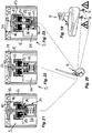
- eine oberhalb eines Waschbeckens vorstehende Auslaufarmatur, bei der das austretende Wasser nach dem Öffnen des Auslaufventils in einem langsam anschwellenden Wasserstrom austritt,
- Fig. 20
- eines der zur Auslaufarmatur gemäß
Figur 19 führenden Eck- oder Anschlussventile, in welchem Eck- oder Anschlussventil ebenfalls eine Einsetzeinheit integriert ist, - Fig. 21
- die in das Eck- oder Anschlussventil gemäß
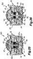
Figur 20 montierte Einsetzeinheit in einem Längsschnitt in der Ruhestellung ihres Ventils, - Fig. 22
- die
Einsetzeinheit aus Figur 21 in einer Zwischenstellung des Ventils, - Fig. 23
- die
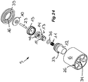
Einsetzeinheit aus Figur 21 und 22 in der Offenstellung des Ventils, - Fig. 24
- die Einsetzeinheit
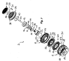
aus den Figuren 21 in einer auseinandergezogenen Perspektivdarstellung ihrer Einzelteile,bis 23 - Fig. 25
- eine ebenfalls als Strahlbelüfter ausgebildete und in einem Längsschnitt gezeigte Einsetzeinheit in einer bevorzugten, weil vereinfachten Ausführungsform in der Ruhestellung des im Einsetzgehäuse vorgesehenen Ventils,
- Fig. 26
- die hier ebenfalls längsgeschnittene Einsetzeinheit aus
Figur 25 in der Offenstellung des im Einsetzgehäuse befindlichen Ventils, - Fig. 27
- die Einsetzeinheit
aus den Figuren 25 und 26 in einer auseinandergezogenen Perspektivdarstellung ihrer Bestandteile in Draufsicht auf die Zuströmseite der Einsetzeinheit, - Fig. 28
- die Einsetzeinheit
aus den Figuren 25 in einer Perspektivdarstellung ihrer Bestandteile in einer Unteransicht auf die Abströmseite dieser Einsetzeinheit,bis 27 - Fig. 29
- eine beispielsweise gegenüber der Einsetzeinheit gemäß den
Figuren 8 geänderte Ausführung einer Einsetzeinheit in der Ruhe- oder Schließposition des im Einsetzgehäuse dieser Einsetzeinheit vorgesehenen Ventils,bis 11 - Fig. 30
- die
Einsetzeinheit aus Figur 29 in der Offenposition des Ventils, und - Fig. 31
- den Ventilsitz des in der Einsetzeinheit gemäß
den Figuren 29 und 30 vorgesehenen Ventils in einer Draufsicht auf die Abströmseite des Ventilsitzes.
- Fig. 1
- an insert unit designed as a jet aerator and shown here in a longitudinal section with an insert housing, in which insert housing a valve is provided which has a valve piston guided displaceably in the insert housing, the sliding movement of the valve piston from the rest position of the valve shown here into an open position with the aid of a Motion damper is slowed down or damped,
- Fig. 2
- the insert unit, also shown here in a longitudinal section, in an intermediate position between the rest position and an open position of the valve,
- Fig. 3
- the insert unit, also cut lengthways here, in the open position of the valve in the insert housing,
- Fig. 4
- the insertion unit from the
Figures 1 to 3 in an exploded perspective view of its components, - Fig. 5
- an insert unit, also designed here as a jet aerator and mountable on the water outlet of a sanitary outlet fitting, in a longitudinal section, the valve provided in the insert housing of this insert unit being in its rest position and a flow rate regulator being interposed in the insert housing of this insert unit, which regulates the volume of water flowing through per unit of time pressure-independent regulates and limits a specified maximum value,
- Fig. 6
- which are already in
Figure 5 Insertion unit shown in a longitudinal section, the insertion unit being here in the open position of the valve, - Fig. 7
- the insertion unit from the
Figures 5 and 6 in an exploded perspective view of its components, - Fig. 8
- an insert unit, also designed here as a jet aerator and shown in a longitudinal section, which insert unit has a valve with a valve piston in its insert housing, which on its flat side facing a valve seat has a ring-shaped surface layer made of elastic Material, the valve is shown here in its rest position,
- Fig. 9
- the insertion unit
Figure 8 in a longitudinally sectioned detailed representation in the area of the valve piston resting against the valve seat in the rest position, - Fig. 10
- the insert unit, which is also cut lengthways
Figures 8 and 9 with the valve in the open position here, - Fig. 11
- the insertion unit from the
Figures 8 to 10 in an exploded perspective view of its components, - Fig. 12
- an insertion unit, shown in longitudinal section and designed as a jet aerator, in the rest position of the valve, the plate-shaped valve piston bearing a rounding or a chamfer on its plate rim, which is in contact with the valve seat in the rest position, which is intended to counteract audible interference during the sliding movement of the valve piston,
- Fig. 13
- the insertion unit
Figure 12 in a longitudinal section in the open position of the valve, - Fig. 14
- the insertion unit from the
Figures 12 and 13 in an exploded perspective view of its components, - Fig. 15
- one in the jet aerators according to the
Figures 1 to 14 Motion damper used in at least a similar design, which has a return spring as a return element having, - Fig. 16
- the unit resulting from the motion damper and return spring
Figure 15 in an exploded perspective view of its components, - Figure 17a
- a longitudinally cut jet splitter for a jet aerator, which is otherwise not shown here, wherein the jet splitter shown here is integrally connected to the damper housing of a motion damper,
- Figure 17b
- the unit consisting of the jet splitter and the integrally molded damper housing of the motion damper and its components
Figure 17a in an exploded view of individual parts, - Figure 18a
- a longitudinally cut jet splitter for a jet aerator, which is otherwise not shown here, wherein the jet splitter shown here has a central insertion opening into which the damper housing of a movement damper is inserted and held securely by means of a latching or snap connection,
- Figure 18b
- the unit consisting of the jet splitter, separate damper housing of a movement damper and the other components of the movement damper
Figure 18a in an exploded view of individual parts, - Fig. 19
- an outlet fitting protruding above a wash basin, in which the escaping water swells slowly after opening the outlet valve Water flow exits,
- Fig. 20
- one of the for the outlet fitting according to
Figure 19 leading angle or connection valves, in which angle or connection valve an insert unit is also integrated, - Fig. 21
- in the angle or connection valve according to
Figure 20 assembled insert unit in a longitudinal section in the rest position of its valve, - Fig. 22
- the insertion unit
Figure 21 in an intermediate position of the valve, - Fig. 23
- the insertion unit
Figures 21 and 22 in the open position of the valve, - Fig. 24
- the insertion unit from the
Figures 21 to 23 in an exploded perspective view of their individual parts, - Fig. 25
- an insert unit, also designed as a jet aerator and shown in a longitudinal section, in a preferred, because simplified embodiment in the rest position of the valve provided in the insert housing,
- Fig. 26
- the insert unit, also cut lengthways here
Figure 25 in the open position of the valve in the insert housing, - Fig. 27
- the insertion unit from the
Figures 25 and 26 in an exploded perspective view of its components in plan view of the inflow side of the insert unit, - Fig. 28
- the insertion unit from the
Figures 25 to 27 in a perspective view of its components in a bottom view of the downstream side of this insert unit, - Fig. 29
- one for example compared to the insertion unit according to the
Figures 8 to 11 Modified design of an insert unit in the rest or closed position of the valve provided in the insert housing of this insert unit, - Fig. 30
- the insertion unit
Figure 29 in the open position of the valve, and - Fig. 31
- the valve seat of the in the insert unit according to the
Figures 29 and 30 provided valve in a plan view of the downstream side of the valve seat.
In den
Die Rückstelleinheit, die im Einsetzgehäuse 6 angeordnet ist und zumindest in der Offenstellung von dem durch das Einsetzgehäuse 6 durchfließenden Wasser umspült wird, weist über das mindestens eine Rückstellelement hinaus auch wenigstens einen Bewegungsdämpfer auf, welcher Bewegungsdämpfer die Bewegung des Ventilkolbens 10 von der Ruhestellung in die Offenposition derart dämpft oder bremst, dass der Ventilkolben 10 den Durchfluss des Wassers im Bereich der Einsetzeinheiten 1, 2, 3, 4, 5, 50, 60 nur langsam öffnet und der Wasserstrom selbst bei schlagartig geöffnetem Auslaufventil dementsprechend nur langsam anschwillt.The reset unit, which is arranged in the
Die in den
Der Dämpferkolben 13 weist an seinem Außenumfang wenigstens eine umfangsseitig offene Nut 14 auf, die mit dem Gehäuseinnenumfang des Dämpfergehäuses 12 den zumindest einen Rückströmkanal umgrenzt. Auf der der Durchströmrichtung der Einsetzeinheit 1, 2, 3, 4, 5, 50, 60 abgewandten Stirnseite des Dämpferkolbens 13 ist eine Ringdichtung 36 vorgesehen, welche Ringdichtung 36 während einer Schiebebewegung des Dämpferkolbens 13 von der Ruhestellung in die Offenposition den zumindest einen Rückströmkanal verschließt.The
Der Ventilkolben 10 steht mit dem Dämpferkolben 13 über eine Kolbenstange 23 in Bewegungsverbindung. Diese Kolbenstange 23 ist an ihrem entgegen der Strömungsrichtung orientierten ersten Stangenende mit dem Ventilkolben 10 und an ihrem, in die Strömungsrichtung weisenden zweiten Stangenende mit dem Dämpferkolben 13 verbunden. Die als Rückstellelement dienende Druckfeder 11 druckbeaufschlagt die der Durchströmrichtung der Einsetzeinheiten 1, 2, 3, 4, 5, 50, 60 abgewandte Stirnseite des Dämpferkolbens 13 und ist zwischen dieser Stirnseite und dem geschlossenen Gehäuseboden des hier hülsenförmigen Dämpfergehäuses 12 angeordnet. Auf der dem Gehäuseboden abgewandten Stirnseite weist das Dämpfergehäuse 12 eine zuströmseitige Gehäuseöffnung auf, die mittels einer Abdeckung 15 verschlossen ist. Die Abdeckung 15 ist ringscheibenförmig ausgebildet und weist eine Ringscheibenöffnung auf, welche die Kolbenstange 14 durchsetzt. Das Dämpfergehäuse 12 ist gegenüber dem Einsetzgehäuse 6 mittels eines ringscheibenförmigen Stopfens abgedichtet, dessen Ringscheibenöffnung ebenfalls von der Kolbenstange 23 durchsetzt wird. Dieser Stopfen 46 ist in das Dämpfergehäuse 12 eingelegt und am Gehäuseinnenumfang des Dämpfergehäuses 12 lösbar gehalten. Der Stopfen 46 wird im Dämpfergehäuse 12 mittels der ringscheibenförmigen Abdeckung 15 gesichert. Dabei dichtet der Stopfen 46 zwischen dem Gehäuseinnenumfang des Dämpfergehäuses 12 und der dessen Ringscheibenöffnung durchsetzenden Kolbenstange 23 ab, so dass das im Dämpfergehäuse 12 befindliche zähflüssige Fluid nicht unbeabsichtigt austreten und vom durchfließenden Wasserstrom mitgerissen werden kann.The
Die Abdeckung 15 ist hier kappenförmig ausgebildet und umschließt mit einer randseitigen Stulpzone den die stirnseitige Öffnung umgrenzenden Wandungsumfang der Gehäusewandung des Dämpfergehäuses 12.The
In der in den
Aus
Die in den
Im Einsetzgehäuse 6 der in den
Die in den
Zwischen dem Strahlzerleger 25 und dem Strömungsgleichrichter 18 ist zumindest ein Einsetzteil 19, 20 und vorzugsweise zwei oder auch mehr als zwei Einsetzteile 19, 20 eingelegt. Diese Einsetzteile 19, 20 weisen jeweils ebenfalls eine Gitter- oder Netzstruktur mit aus einander an Kreuzungsknoten kreuzenden Stegen auf, die zwischen sich ebenfalls Durchflussöffnungen 21 umgrenzen. Diese Einsetzteile sollen die im Strahlzerleger 25 erzeugten Einzelstrahlen noch zusätzlich aufteilen und die Durchmischung mit Umgebungsluft begünstigen. Jedes der Einsetzteile 19, 20 weist an seinem Außenumfang eine Ringwand 22 auf, die mit den Stegen der Gitter- oder Netzstruktur dieser Einsetzteile 19, 20 einstückig verbunden ist. Die übereinander gestapelten Ringwände 22 der einander benachbarten Einsetzteile 19, 20 liegen aufeinander auf und sind so bemessen, dass die Gitter- oder Netzstruktur in einem definierten Abstand zueinander angeordnet sind. Die Einsetzteile 19, 20 sind drehgesichert im Einsetzgehäuse 6 gehalten, wobei die Stege eines abströmseitigen Einsetzteiles 20 mit den Durchflussöffnungen 21 des dazu benachbarten zuströmseitigen Einsetzteiles 19 fluchten sollten.Between the
Zur Drehsicherung der Einsetzteile 19, 20 weisen diese am Außenumfang ihrer Ringwände 22 wenigstens einen Sicherungsvorsprung 27 oder mindestens eine Sicherungseinsenkung auf, welches Sicherungsmittel 27 mit einer komplementären Gegeneinsenkung 28 oder einem Gegenvorsprung am Gehäuseinnenumfang des Einsetzgehäuses 6 zusammenwirkt. Bei den hier gezeigten und als Strahlbelüfter ausgebildeten Einsetzeinheiten 1, 2, 3, 4, 50, 60 ist das Dämpfergehäuse 12 mit dem Strahlzerleger 25 lösbar verbindbar. Der Strahlzerleger 25 weist dazu eine zentrale Einsetzöffnung 29 auf. Das Dämpfergehäuse 12 hat außenumfangsseitig einen umlaufenden und hier als Ringabsatz ausgebildeten Einsetzanschlag 33. Dabei ist das Dämpfergehäuse 12 von der Zuströmseite aus in die Einsetzöffnung 29 einsetzbar, bis der Einsetzanschlag 33 an einem Gegenanschlag am Strahlzerleger 25 anliegt. Dieser Gegenanschlag wird hier durch den die Einsetzöffnung 29 umgrenzenden Umfangsrand des Strahlzerlegers 25 gebildet. Das Dämpfergehäuse 12 ist in der Einsetzöffnung 29 des Strahlzerlegers 25 mittels einer Schnapp- oder Rastverbindung gehalten.To prevent the
In den
Das Dämpfergehäuse 12 steht über die Abströmseite des Strahlzerlegers 25 vor. Dazu sind auch in den ringförmigen Einsetzteilen 19, 20 und gegebenenfalls auch im Strömungsgleichrichter zentrale Einsetzöffnungen 27, 28 vorgesehen, welche das Dämpfergehäuse 12 durchsetzt.The
Der Bewegungsdämpfer hat hier eine unter dem Druck des anströmenden Wassers wirksame Druckstufe, während der sich das Ventil von seiner Ruhestellung in die Offenstellung bewegt, und eine Zugstufe, während der eine Rückstellbewegung des Dämpferkolbens 13 von der Offenstellung in die Ruhestellung des Ventils erfolgt. Um den Wasserstrom nach dem Öffnen eines der Einsetzeinheit 1, 2, 3, 4, 5, 50, 60 vor- oder nachgeschalteten Auslaufventils ausreichend langsam anschwellen zu lassen, ist die Druckstufe des Bewegungsdämpfers härter als die Zugstufe ausgestaltet. Auf der der Strömungsrichtung abgewandten Stirnseite des Dämpferkolbens 13 ist dazu eine Ringdichtung 36 vorgesehen, welche sich während der Druckstufe des Bewegungsdämpfers derart an diese Stirnseite anlegt, dass die Ringdichtung 36 die Rückströmkanäle verschließt und das zähflüssige Fluid nur durch den zentral im Dämpferkolben 13 vorgesehenen Verbindungskanal hindurchfließen kann. Da somit der Durchflussquerschnitt für das Fluid während der Druckstufe reduziert ist, ist dieser Durchfluss des Fluids durch den zumindest einen Verbindungskanal im Vergleich zur Zugstufe erschwert.The motion damper has a pressure stage under the pressure of the incoming water, during which the valve moves from its rest position to the open position, and a rebound stage, during which a return movement of the
Die in den
Die in den
Bei den in den
Bei der in den
In den
Zu dem gleichen Zweck ist im Ventilkolben 10 der in den
Der ebenfalls tellerförmig ausgestaltete Ventilkolben 10 der in den
Die in den
Der Ventilkolben 10 der in den
Auch bei der Einsetzeinheit 60 ist ein Dämpfergehäuse 12 vorgesehen, das am Strahlzerleger 25 verrastbar und vorzugsweise lösbar verrastbar ist. Der Einsetzanschlag 33 ist dazu am zuströmseitigen Gehäuseumfang des Dämpfergehäuses 12 vorgesehen und wirkt hier mit einem Gegenanschlag zusammen, der als eine, die Einsetzöffnung 29 im Strahlzerleger 25 zuströmseitig umgrenzende Ringnut oder ein Ringabsatz ausgebildet ist. Am abströmseitigen, die Einsetzöffnung 29 umgrenzenden Randbereich des Strahlzerlegers 25 ist ein umlaufender Kragen 62 angeformt, der mit seinem freien Kragenrand einen Ringabsatz am Gehäuseumfang des Dämpfergehäuses 12 verrastend hintergreift und das Dämpfergehäuse 12 damit sicher am Strahlzerleger 25 hält. Dieser Ringabsatz ist hier durch einen umfangsseitig vorstehenden Ringflansch 63 gebildet, welcher Ringflansch 63 auf den die zentrale Einsetzöffnung 27 des abströmseitig nachgeschalteten Einsetzteiles 19 umgrenzenden Stegen der Gitter- oder Netzstruktur dieses Einsetzteiles 19 aufliegt.A
Der Ventilkolben 10 der Einsetzeinheit 60 ist hier stufenförmig ausgebildet, wobei die Stufen in Durchströmrichtung einen von Stufe zu Stufe reduzierten Stufendurchmesser haben. Dabei ist die die zuströmseitige Stirnfläche des Ventilkolbens 10 bildende Stufe teller- oder plattenförmig ausgebildet. Die elastische Oberflächenschicht 40 kann auch hier an ihrer zuströmseitigen Stirnfläche eine zentrale Öffnung aufweisen, um bei Bedarf einen Anspritzpunkt am Ventilkolben 10 aufzunehmen.The
Aus der in
- 11
-
Einsetzeinheit (gemäß den
Fig. 1 bis 4 )Insertion unit (according to theFigs. 1 to 4 ) - 22
-
Einsetzeinheit (gemäß den
Fig. 5 bis 7 )Insertion unit (according to theFigures 5 to 7 ) - 33
-
Einsetzeinheit (gemäß den
Fig. 8 bis 11 )Insertion unit (according to theFigs. 8-11 ) - 44th
-
Einsetzeinheit (gemäß den
Fig. 12 bis 14 )Insertion unit (according to theFigures 12-14 ) - 55
-
Einsetzeinheit (gemäß den
Fig. 21 bis 24 )Insertion unit (according to theFigures 21 to 24 ) - 66
- EinsetzgehäuseInsert housing
- 6a6a
- abströmseitiges GehäuseteilHousing part on the downstream side
- 6b6b
- zuströmseitiges GehäuseteilUpstream housing part
- 77th
- Eck- oder AnschlussventilAngle or connection valve
- 88th
- WasserauslaufWater outlet
- 99
- AuslaufarmaturOutlet fitting
- 1010
- VentilkolbenValve piston
- 1111
- DruckfederCompression spring
- 1212
- DämpfergehäuseDamper housing
- 1313
- DämpferkolbenDamper piston
- 1414th
- NutGroove
- 1515th
- Abdeckungcover
- 1616
- VentilsitzValve seat
- 1717th
- BelüftungsöffnungVentilation opening
- 1818th
-
Strömungsgleichrichter (gemäß den
Fig. 1 bis 14 )Flow straightener (according toFigs. 1 to 14 ) - 1919th
- EinsetzteilInsert part
- 2020th
- EinsetzteilInsert part
- 2121st
- DurchflussöffnungFlow opening
- 2222nd
- RingwandRing wall
- 2323
- KolbenstangePiston rod
- 2424
- DurchflusslöcherFlow holes
- 2525th
- StrahlzerlegerJet splitter
- 2626th
-
Strömungsgleichrichter (gemäß den
Fig. 21 bis 24 )Flow straightener (according toFigures 21 to 24 ) - 2727
- SicherungsvorsprungSafety tab
- 2828
- GegeneinsenkungCounter-sinking
- 2929
- EinsetzöffnungInsertion opening
- 3030th
- VorsatzsiebAttachment screen
- 3131
- DurchflussmengenreglerFlow regulator
- 3232
- DrosselkörperThrottle body
- 3333
- EinsetzanschlagInsertion stop
- 3434
- Einsetzöffnung (im Strömungsgleichrichter 18)Insertion opening (in flow straightener 18)
- 3535
-
Einsetzöffnung (in den Einsetzteilen 19, 20)Insertion opening (in the
insert parts 19, 20) - 3636
- RingdichtungRing seal
- 3737
- RegelkernRule core
- 3838
- UmfangswandungPerimeter wall
- 3939
- ZwischenstückIntermediate piece
- 4040
- OberflächenschichtSurface layer
- 4141
- EinformungMolding
- 4242
- Fasechamfer
- 4343
- VerbindungskanalConnection channel
- 4444
- EinformungMolding
- 4545
- EinstecköffnungInsertion opening
- 4646
- StopfenPlug
- 4747
- ZapfenCones
- 5050
-
Einsetzeinheit (gemäß den
Figuren 25 bis 28 )Insertion unit (according to theFigures 25 to 28 ) - 5151
- Bypass-KanalBypass channel
- 6060
-
Einsetzeinheit (gemäß den
Figuren 29 und 30 )Insertion unit (according to theFigures 29 and 30 ) - 6161
- RingnutRing groove
- 6262
- Kragencollar
- 6363
- RingflanschRing flange
- 6464
- FührungsstegeGuide bars
- 6565
-
Ringflansch an der Oberflächenschicht 40Annular flange on the
surface layer 40
Claims (44)
- Sanitary insert unit (1, 2, 3, 4, 5, 50, 60) having an insert housing (6), in which insert housing (6) a valve having a valve piston (10) is provided, which valve piston (10) is guided in a displaceable manner in the insert housing (6) and is movable from a rest position, under the pressure of the inflowing water, counter to the restoring force of at least one restoring element, wherein the insert unit (1, 2, 3, 4, 5, 50, 60) has at least one movement damper, which damps or brakes the movement of the valve piston (10) from the rest position into the open position, characterized in that the at least one movement damper is configured as a hydraulic damper which has a damper housing (12), in which damper housing (12) a damper piston (13) is guided in a displaceable manner, wherein, during a sliding movement from the rest position into the open position, the damper piston (13) displaces oil or similar viscous fluid from one side of the damper piston (13) to the other side of the damper piston (13) through at least one connecting duct.
- Sanitary insert unit according to Claim 1, characterized in that the at least one restoring element is in the form of a restoring spring.
- Sanitary insert unit according to Claim 1 or 2, characterized in that the at least one restoring element is in the form of a compression spring (11).
- Sanitary insert unit according to one of Claims 1 to 3, characterized in that the valve piston (10) is connected to the damper piston (13) in terms of movement via a piston rod (23).
- Sanitary insert unit according to Claim 4, characterized in that the piston rod (23) is connected to the valve piston (10) at its first rod end oriented counter to the direction of flow, and is connected to the damper piston (13) at its second rod end directed in the direction of flow.
- Sanitary insert unit according to one of Claims 1 to 5, characterized in that the at least one restoring element applies pressure to that end side of the damper piston (13) that faces away from the flow-through direction of the insert unit (1, 2, 3, 4, 5, 50, 60).
- Sanitary insert unit according to Claim 6, characterized in that the at least one restoring element is arranged between a closed housing bottom of the damper housing (12) and that end side of the damper piston (13) that faces away from the flow-through direction.
- Sanitary insert unit according to one of Claims 4 to 7, characterized in that the damper housing (12) has an end-side housing opening, which is closed by means of at least one cover (15) in the form of an annular disc, the annular-disc opening of which has the piston rod (23) passing through it.
- Sanitary insert unit according to Claim 8, characterized in that the damper housing (12) is sealed off from the insert housing (6) by means of a plug (46) in the form of an annular disc, the annular-disc opening of which has the piston rod (23) passing through it.
- Sanitary insert unit according to Claim 9, characterized in that the plug (46) is held preferably in a releasable manner on the housing inner circumference of the damper housing (12).
- Sanitary insert unit according to Claim 9 or 10, characterized in that the plug (46) provides sealing between the housing inner circumference of the damper housing (12) and the piston rod (43) passing through the annular-disc opening thereof.
- Sanitary insert unit according to one of Claims 1 to 11, characterized in that, in the rest position, the valve piston (10) of the valve butts preferably partially or with play against a circumferential rim in the insert housing (6), said circumferential rim being in the form of a valve seat (16) and bounding a flow-through opening.
- Sanitary insert unit according to Claim 12, characterized in that the valve piston (10) of the valve is spaced apart, in the open position, from the circumferential rim, in the form of a valve seat (16), in the insert housing (6).
- Sanitary insert unit according to one of Claims 1 to 13, characterized in that the sanitary insert unit (1, 2, 3, 4, 50, 60) is in the form of an unaerated jet former or of a jet aerator, which jet aerator mixes the water flowing through with ambient air when in use.
- Sanitary insert unit according to Claim 14, characterized in that the jet aerator has a jet splitter (25), which divides the water flowing through into a multiplicity of individual jets when in use.
- Sanitary insert unit according to Claim 15, characterized in that the jet splitter (25) is in the form of a perforated plate, which has a multiplicity of flow-through holes (24) that form individual jets.
- Sanitary insert unit according to Claim 15 or 16, characterized in that, in the circumferential wall of the insert housing (6), at least one aeration opening (17) is provided, which is provided in an annular zone of the housing circumferential wall of the insert housing (6), said annular zone being arranged preferably directly beneath the jet splitter (25) in the direction of flow.
- Sanitary insert unit according to one of Claims 15 to 17, characterized in that the jet aerator has an outflow-side flow straightener (18) having a honeycomb, lattice or mesh structure, which honeycomb, lattice or mesh structure is formed by webs that intersect at intersecting points.
- Sanitary insert unit according to Claim 18, characterized in that the honeycomb, lattice or mesh structure of the flow straightener (18) is integrally formed on the insert housing (6).
- Sanitary insert unit according to Claim 18 or 19, characterized in that, between the jet splitter (25) and the flow straightener (18), at least one insert part (19, 20) having a lattice or mesh structure made up of webs that intersect at intersecting points is provided.
- Sanitary insert unit according to Claim 20, characterized in that the at least one insert part (19, 20) has, at least on its outer circumference, an encircling annular wall (22), on which annular wall (22) the lattice or mesh structure of this insert part (19, 20) is integrally formed.
- Sanitary insert unit according to one of Claims 15 to 21, characterized in that the damper housing (12) is releasably connectable or integrally connected to the jet splitter (25).
- Sanitary insert unit according to Claim 22, characterized in that the damper housing (12) is held in a preferably central insertion opening (29) of the jet splitter (25), in particular by means of a latching or snap-fit connection.
- Sanitary insert unit according to one of Claims 15 to 23, characterized in that the jet splitter (25) and preferably also the flow straightener (26) and optionally also the at least one insert part (19, 20) provided between the jet splitter (25) and flow straightener (26) each have an insertion opening (29, 34, 35), which insertion opening(s) has/have the damper housing (12) passing through it/them.
- Sanitary insert unit according to one of Claims 1 to 24, characterized in that, during a sliding movement when in use, the damper piston (13) displaces oil or similar viscous fluid through at least one connecting duct from the rest position into the open position and through at least one return-flow duct from the open position into the rest position.
- Sanitary insert unit according to one of Claims 23 to 25, characterized in that an insertion stop (33) is provided on the outer circumference of the damper housing (12), and in that the damper housing (12) is insertable into the insertion opening (29) in the jet splitter (25) until the insertion stop (33) butts against a mating stop on the jet splitter (25).
- Sanitary insert unit according to Claim 25 or 26, characterized in that the damper piston (13) has, on its outer circumference, at least one circumferentially open groove (14), which bounds the at least one return-flow duct together with the housing inner circumference of the damper housing (12).
- Sanitary insert unit according to one of Claims 25 to 27, characterized in that the at least one connecting duct has, on the inflow side, a duct inlet, which is arranged on that piston end side of the damper piston (13) that faces the housing bottom of the damper housing (12).
- Sanitary insert unit according to Claim 28, characterized in that the at least one connecting duct has, on the outflow side, a duct portion which is provided preferably in a groove-like indentation (44) between the piston rod (23) and an inner circumferential wall, which inner circumferential wall bounds a plug-in opening (45) in the damper piston (13), said plug-in opening (45) accommodating one rod end of the piston rod (23).
- Sanitary insert unit according to one of Claims 1 to 29, characterized in that the movement damper has a pressure stage, which is active under the pressure of the inflowing water and during which the valve moves from its rest position into the open position, and a rebound stage, during which a restoring movement of the damper piston from the open position into the rest position of the valve takes place.
- Sanitary insert unit according to Claim 30, characterized in that the pressure stage of the movement damper is configured to be harder than the rebound stage.
- Sanitary insert unit according to one of Claims 25 to 31, characterized in that a ring seal (36) is provided on that end side of the damper piston (13) that faces away from the flow-through direction of the insert unit (1, 2, 3, 4, 5, 50, 60), said ring seal (36) closing the at least one return-flow duct during a sliding movement of the damper piston (13) from the rest position into the open position.
- Sanitary insert unit according to Claim 12 or according to one of Claims 13 to 32 where referring back to Claim 12, characterized in that the preferably plate-shaped valve piston (10) bears a surface layer (40) made of elastic material, at least in the annular zone of the inflow-side piston end side, said annular zone butting against the valve seat (16) in the rest position.
- Sanitary insert unit according to Claim 12 or according to one of Claims 13 to 33 where referring back to Claim 12, characterized in that the valve piston (10) bears a surface layer (40) made of elastic material on its end side facing the valve seat (16), said surface layer (40) being mounted on the valve piston (10) so as to be displaceable in a radial direction.
- Sanitary insert unit according to Claim 34, characterized in that the surface layer (40) is configured in the form of an annular disc, and in that the annular-disc opening in this surface layer (40) has a peg (47), protruding from the valve piston (10), passing through it.
- Sanitary insert unit according to Claim 34, characterized in that at least one plug-in peg is integrally formed on the flat side, facing the valve piston (10), of the surface layer (40), which plug-in peg is held in an associated peg opening in the valve piston (10).
- Sanitary insert unit according to Claim 13 or according to one of Claims 14 to 36 where referring back to Claim 13, characterized in that the circumferential rim, in the form of a valve seat (16), in the insert housing (6) has at least one peripheral indentation (41), which indentation (41) is water-permeable even in the rest position of the valve.
- Sanitary insert unit according to Claim 12 or according to one of Claims 13 to 37 where referring back to Claim 12, characterized in that an annular or sleeve-shaped intermediate piece (39) is provided on the inflow side of the insert housing (6), which intermediate piece (39) has the flow-through opening serving as a valve seat (16).
- Sanitary insert unit according to Claim 38, characterized in that a dome screen or filter screen (30) and preferably also a flow rate regulator (31) arranged therebetween are held on the inflow side of the intermediate piece (39).
- Sanitary insert unit according to one of Claims 34 to 39, characterized in that the surface layer (40) engages with its circumferential-rim region behind the valve piston (10) and in particular behind a subregion, protruding in a flange-like manner, of the valve piston (10).
- Sanitary insert unit according to Claim 12 or according to one of Claims 13 to 40 where referring back to Claim 12, characterized in that guide ribs or guide webs (64) are provided on the outflow side of the valve seat (16), said guide ribs or guide webs (64) each forming a linear piston guide for the valve piston (10) during the sliding movement of the valve piston (10).
- Sanitary insert unit according to Claim 41, characterized in that the surface layer (40) has a circumferentially protruding annular flange (65), and in that the guide ribs or guide webs (64) impinge on the annular flange (65) of the surface layer (40) .
- Use of a sanitary insert unit according to one of Claims 1 to 42, characterized in that the sanitary insert unit (5) is interposed in a corner valve or connection valve (7) of a sanitary water pipe.
- Use of a sanitary insert unit according to one of Claims 1 to 42, characterized in that the sanitary insert unit (1, 2, 3, 4, 50, 60) is mounted in the water outlet of a sanitary outlet fitting (9).
Applications Claiming Priority (2)
| Application Number | Priority Date | Filing Date | Title |
|---|---|---|---|
| DE202016003402.3U DE202016003402U1 (en) | 2016-05-28 | 2016-05-28 | Sanitary insert unit |
| PCT/EP2017/000503 WO2017207080A1 (en) | 2016-05-28 | 2017-04-24 | Sanitary insertion unit |
Publications (2)
| Publication Number | Publication Date |
|---|---|
| EP3464738A1 EP3464738A1 (en) | 2019-04-10 |
| EP3464738B1 true EP3464738B1 (en) | 2020-08-19 |
Family
ID=58632923
Family Applications (1)
| Application Number | Title | Priority Date | Filing Date |
|---|---|---|---|
| EP17719483.4A Active EP3464738B1 (en) | 2016-05-28 | 2017-04-24 | Sanitary insertion unit |
Country Status (6)
| Country | Link |
|---|---|
| US (1) | US11434629B2 (en) |
| EP (1) | EP3464738B1 (en) |
| JP (1) | JP6820348B2 (en) |
| CN (3) | CN107435358B (en) |
| DE (1) | DE202016003402U1 (en) |
| WO (1) | WO2017207080A1 (en) |
Families Citing this family (3)
| Publication number | Priority date | Publication date | Assignee | Title |
|---|---|---|---|---|
| DE202016003402U1 (en) * | 2016-05-28 | 2017-08-30 | Neoperl Gmbh | Sanitary insert unit |
| US11591780B2 (en) * | 2020-04-15 | 2023-02-28 | Yeuu Deng Sanitary Facilities Industrial Co., Ltd. | Faucet aerator |
| DE202020004716U1 (en) * | 2020-11-02 | 2020-12-18 | Dietmar Henschel | Jet regulator insert with integrated check valve |
Family Cites Families (27)
| Publication number | Priority date | Publication date | Assignee | Title |
|---|---|---|---|---|
| FR717041A (en) | 1931-05-13 | 1931-12-31 | Drain pipe for liquid dispenser | |
| US3848632A (en) * | 1973-10-09 | 1974-11-19 | Anderson Greenwood & Co | Valve |
| US4099536A (en) * | 1976-07-21 | 1978-07-11 | Warren Automatic Tool Co. | Method and apparatus for controlling a surging flow in a closed conduit |
| DE2650934A1 (en) * | 1976-11-08 | 1978-05-11 | Waletzko Alfred Apparatebau | Back flow preventer between drinking and washing water pipework - has guide rings fitted between valve and guide rod |
| FR2473670B1 (en) * | 1980-01-15 | 1985-06-28 | Electricite De France | SAFETY VALVE EQUIPPED WITH A HYDRAULIC BRAKE AND HYDRAULIC BRAKE LIKELY TO BE INSERTED IN AN EXISTING VALVE |
| JPS58139443A (en) | 1982-02-15 | 1983-08-18 | Toshiba Corp | Manufacture of semiconductor device |
| US4531542A (en) * | 1983-08-22 | 1985-07-30 | Baird Manufacturing Company | Fluid dampened back pressure regulator |
| DE3446425C2 (en) | 1984-12-20 | 1994-01-20 | Vortex Gmbh Dt | Backflow preventer for a fluid |
| US4867603A (en) * | 1989-02-01 | 1989-09-19 | Chang Shih Chih | Device for preventing flooding caused by sprinkler failure |
| US5071071A (en) * | 1990-06-05 | 1991-12-10 | Chao Tien Hsiung | Aerator structure for a water faucet |
| DE4436193A1 (en) | 1994-10-11 | 1996-04-18 | Grohe Armaturen Friedrich | Water tap jet control with perforated plate |
| DE29702063U1 (en) | 1997-02-06 | 1997-03-20 | Kwc Ag | Spout arrangement for a sanitary fitting |
| DE29703335U1 (en) | 1997-02-25 | 1997-04-10 | Wildfang Dieter Gmbh | Backflow preventer |
| DE19806451A1 (en) * | 1998-02-17 | 1999-08-19 | Huthmann | Flow regulator |
| DE29902906U1 (en) | 1999-02-18 | 1999-05-12 | Wildfang Dieter Gmbh | Installation part for a sanitary outlet fitting |
| DE10027987B4 (en) * | 2000-06-06 | 2005-12-22 | Neoperl Gmbh | aerator |
| CN1318704C (en) | 2001-11-09 | 2007-05-30 | 东陶机器株式会社 | Water discharge switching device |
| CN101070709A (en) * | 2006-05-10 | 2007-11-14 | 周华松 | Novel water-saving device |
| DE102006057795B3 (en) | 2006-12-06 | 2008-02-21 | Neoperl Gmbh | Sanitary installation unit for use as aerator, has filter sieve with dirt outlet opening, which has increased opening cross-section compared to sieve openings of filter sieve, where dirt outlet opening ends into bypass or cleaning channel |
| CN201420282Y (en) * | 2009-05-21 | 2010-03-10 | 泉州中宇卫浴科技实业有限公司 | Clear stream type constant-flow water saving bubbler |
| CN201620440U (en) * | 2009-12-31 | 2010-11-03 | 泉州中宇卫浴科技实业有限公司 | Novel water-drop-shaped bubble former |
| JP3182863U (en) | 2010-02-12 | 2013-04-18 | 浩瀚国際有限公司 | Water-saving valve |
| DE202014007070U1 (en) * | 2014-09-04 | 2015-12-08 | Neoperl Gmbh | shut-off valve |
| US9404596B2 (en) * | 2014-12-31 | 2016-08-02 | Bao-Tang Chen | Multifunctional check valve device |
| CN104631570A (en) * | 2015-01-09 | 2015-05-20 | 厦门绿延节水科技有限公司 | Bubbler |
| DE202015000856U1 (en) | 2015-02-03 | 2016-05-04 | Neoperl Gmbh | Sanitary outlet element |
| DE202016003402U1 (en) * | 2016-05-28 | 2017-08-30 | Neoperl Gmbh | Sanitary insert unit |
-
2016
- 2016-05-28 DE DE202016003402.3U patent/DE202016003402U1/en active Active
- 2016-12-21 CN CN201611185825.0A patent/CN107435358B/en active Active
- 2016-12-21 CN CN201621412754.9U patent/CN206418551U/en not_active Withdrawn - After Issue
-
2017
- 2017-04-24 JP JP2018550746A patent/JP6820348B2/en active Active
- 2017-04-24 US US16/085,643 patent/US11434629B2/en active Active
- 2017-04-24 CN CN201780013246.4A patent/CN108699821B/en active Active
- 2017-04-24 WO PCT/EP2017/000503 patent/WO2017207080A1/en active Search and Examination
- 2017-04-24 EP EP17719483.4A patent/EP3464738B1/en active Active
Non-Patent Citations (1)
| Title |
|---|
| None * |
Also Published As
| Publication number | Publication date |
|---|---|
| JP2019515159A (en) | 2019-06-06 |
| CN206418551U (en) | 2017-08-18 |
| US11434629B2 (en) | 2022-09-06 |
| US20200318329A1 (en) | 2020-10-08 |
| DE202016003402U1 (en) | 2017-08-30 |
| CN107435358A (en) | 2017-12-05 |
| EP3464738A1 (en) | 2019-04-10 |
| CN108699821B (en) | 2020-06-02 |
| CN107435358B (en) | 2020-03-20 |
| JP6820348B2 (en) | 2021-01-27 |
| WO2017207080A1 (en) | 2017-12-07 |
| CN108699821A (en) | 2018-10-23 |
Similar Documents
| Publication | Publication Date | Title |
|---|---|---|
| EP2710441B1 (en) | Flow rate regulator | |
| EP2753766B1 (en) | Throughflow controller | |
| EP3054058B1 (en) | Sanitary insert unit | |
| EP3199714B1 (en) | Sanitary outlet unit | |
| EP2384382B9 (en) | Flow quantity regulator | |
| DE202007003264U1 (en) | Sanitary installation element | |
| EP3268830B1 (en) | Flow-rate controller unit | |
| DE102010012326A1 (en) | aerator | |
| EP3464738B1 (en) | Sanitary insertion unit | |
| EP3220022B1 (en) | Flow quantity controller unit | |
| EP2087181A1 (en) | Sanitary installation element | |
| EP1604137A1 (en) | Insertable component which can be inserted into a gas or liquid line | |
| DE102007010618B4 (en) | Sanitary installation element | |
| WO2004083698A1 (en) | Insertion part for inserting into a gas or liquid line | |
| DE102016006498B4 (en) | Sanitary insert unit | |
| WO2005052421A1 (en) | Backflow preventer | |
| DE102016003010B4 (en) | aerator | |
| DE10201626A1 (en) | check valve | |
| EP1029989B1 (en) | Insert for an outlet of sanitary equipment | |
| DE102006036148A1 (en) | Mixer cartridge for insertion into sanitary fitting, has cartridge base closing cartridge housing in direction of retainer of sanitary fitting, where base is held opposite to cartridge housing in movable manner | |
| DE102017128758A1 (en) | Sanitary insert unit | |
| DE102015001383B4 (en) | Sanitary outlet element | |
| DE102016003011A1 (en) | Flow regulator unit | |
| DE10223789B4 (en) | Jet regulator for a sanitary outlet fitting | |
| DE102011122957B3 (en) | Sanitary installation part |
Legal Events
| Date | Code | Title | Description |
|---|---|---|---|
| STAA | Information on the status of an ep patent application or granted ep patent |
Free format text: STATUS: UNKNOWN |
|
| STAA | Information on the status of an ep patent application or granted ep patent |
Free format text: STATUS: THE INTERNATIONAL PUBLICATION HAS BEEN MADE |
|
| PUAI | Public reference made under article 153(3) epc to a published international application that has entered the european phase |
Free format text: ORIGINAL CODE: 0009012 |
|
| STAA | Information on the status of an ep patent application or granted ep patent |
Free format text: STATUS: REQUEST FOR EXAMINATION WAS MADE |
|
| 17P | Request for examination filed |
Effective date: 20190102 |
|
| AK | Designated contracting states |
Kind code of ref document: A1 Designated state(s): AL AT BE BG CH CY CZ DE DK EE ES FI FR GB GR HR HU IE IS IT LI LT LU LV MC MK MT NL NO PL PT RO RS SE SI SK SM TR |
|
| AX | Request for extension of the european patent |
Extension state: BA ME |
|
| DAV | Request for validation of the european patent (deleted) | ||
| DAX | Request for extension of the european patent (deleted) | ||
| GRAP | Despatch of communication of intention to grant a patent |
Free format text: ORIGINAL CODE: EPIDOSNIGR1 |
|
| STAA | Information on the status of an ep patent application or granted ep patent |
Free format text: STATUS: GRANT OF PATENT IS INTENDED |
|
| INTG | Intention to grant announced |
Effective date: 20200206 |
|
| GRAJ | Information related to disapproval of communication of intention to grant by the applicant or resumption of examination proceedings by the epo deleted |
Free format text: ORIGINAL CODE: EPIDOSDIGR1 |
|
| STAA | Information on the status of an ep patent application or granted ep patent |
Free format text: STATUS: REQUEST FOR EXAMINATION WAS MADE |
|
| GRAS | Grant fee paid |
Free format text: ORIGINAL CODE: EPIDOSNIGR3 |
|
| STAA | Information on the status of an ep patent application or granted ep patent |
Free format text: STATUS: GRANT OF PATENT IS INTENDED |
|
| GRAP | Despatch of communication of intention to grant a patent |
Free format text: ORIGINAL CODE: EPIDOSNIGR1 |
|
| INTC | Intention to grant announced (deleted) | ||
| INTG | Intention to grant announced |
Effective date: 20200617 |
|
| GRAA | (expected) grant |
Free format text: ORIGINAL CODE: 0009210 |
|
| STAA | Information on the status of an ep patent application or granted ep patent |
Free format text: STATUS: THE PATENT HAS BEEN GRANTED |
|
| AK | Designated contracting states |
Kind code of ref document: B1 Designated state(s): AL AT BE BG CH CY CZ DE DK EE ES FI FR GB GR HR HU IE IS IT LI LT LU LV MC MK MT NL NO PL PT RO RS SE SI SK SM TR |
|
| REG | Reference to a national code |
Ref country code: CH Ref legal event code: EP |
|
| REG | Reference to a national code |
Ref country code: DE Ref legal event code: R096 Ref document number: 502017006818 Country of ref document: DE |
|
| REG | Reference to a national code |
Ref country code: AT Ref legal event code: REF Ref document number: 1304080 Country of ref document: AT Kind code of ref document: T Effective date: 20200915 |
|
| REG | Reference to a national code |
Ref country code: IE Ref legal event code: FG4D Free format text: LANGUAGE OF EP DOCUMENT: GERMAN |
|
| REG | Reference to a national code |
Ref country code: CH Ref legal event code: NV Representative=s name: GACHNANG AG PATENTANWAELTE, CH |
|
| REG | Reference to a national code |
Ref country code: LT Ref legal event code: MG4D |
|
| REG | Reference to a national code |
Ref country code: NL Ref legal event code: MP Effective date: 20200819 |
|
| PG25 | Lapsed in a contracting state [announced via postgrant information from national office to epo] |
Ref country code: FI Free format text: LAPSE BECAUSE OF FAILURE TO SUBMIT A TRANSLATION OF THE DESCRIPTION OR TO PAY THE FEE WITHIN THE PRESCRIBED TIME-LIMIT Effective date: 20200819 Ref country code: GR Free format text: LAPSE BECAUSE OF FAILURE TO SUBMIT A TRANSLATION OF THE DESCRIPTION OR TO PAY THE FEE WITHIN THE PRESCRIBED TIME-LIMIT Effective date: 20201120 Ref country code: PT Free format text: LAPSE BECAUSE OF FAILURE TO SUBMIT A TRANSLATION OF THE DESCRIPTION OR TO PAY THE FEE WITHIN THE PRESCRIBED TIME-LIMIT Effective date: 20201221 Ref country code: LT Free format text: LAPSE BECAUSE OF FAILURE TO SUBMIT A TRANSLATION OF THE DESCRIPTION OR TO PAY THE FEE WITHIN THE PRESCRIBED TIME-LIMIT Effective date: 20200819 Ref country code: NO Free format text: LAPSE BECAUSE OF FAILURE TO SUBMIT A TRANSLATION OF THE DESCRIPTION OR TO PAY THE FEE WITHIN THE PRESCRIBED TIME-LIMIT Effective date: 20201119 Ref country code: BG Free format text: LAPSE BECAUSE OF FAILURE TO SUBMIT A TRANSLATION OF THE DESCRIPTION OR TO PAY THE FEE WITHIN THE PRESCRIBED TIME-LIMIT Effective date: 20201119 Ref country code: HR Free format text: LAPSE BECAUSE OF FAILURE TO SUBMIT A TRANSLATION OF THE DESCRIPTION OR TO PAY THE FEE WITHIN THE PRESCRIBED TIME-LIMIT Effective date: 20200819 Ref country code: SE Free format text: LAPSE BECAUSE OF FAILURE TO SUBMIT A TRANSLATION OF THE DESCRIPTION OR TO PAY THE FEE WITHIN THE PRESCRIBED TIME-LIMIT Effective date: 20200819 |
|
| PG25 | Lapsed in a contracting state [announced via postgrant information from national office to epo] |
Ref country code: PL Free format text: LAPSE BECAUSE OF FAILURE TO SUBMIT A TRANSLATION OF THE DESCRIPTION OR TO PAY THE FEE WITHIN THE PRESCRIBED TIME-LIMIT Effective date: 20200819 Ref country code: RS Free format text: LAPSE BECAUSE OF FAILURE TO SUBMIT A TRANSLATION OF THE DESCRIPTION OR TO PAY THE FEE WITHIN THE PRESCRIBED TIME-LIMIT Effective date: 20200819 Ref country code: LV Free format text: LAPSE BECAUSE OF FAILURE TO SUBMIT A TRANSLATION OF THE DESCRIPTION OR TO PAY THE FEE WITHIN THE PRESCRIBED TIME-LIMIT Effective date: 20200819 Ref country code: NL Free format text: LAPSE BECAUSE OF FAILURE TO SUBMIT A TRANSLATION OF THE DESCRIPTION OR TO PAY THE FEE WITHIN THE PRESCRIBED TIME-LIMIT Effective date: 20200819 Ref country code: IS Free format text: LAPSE BECAUSE OF FAILURE TO SUBMIT A TRANSLATION OF THE DESCRIPTION OR TO PAY THE FEE WITHIN THE PRESCRIBED TIME-LIMIT Effective date: 20201219 |
|
| PG25 | Lapsed in a contracting state [announced via postgrant information from national office to epo] |
Ref country code: CZ Free format text: LAPSE BECAUSE OF FAILURE TO SUBMIT A TRANSLATION OF THE DESCRIPTION OR TO PAY THE FEE WITHIN THE PRESCRIBED TIME-LIMIT Effective date: 20200819 Ref country code: DK Free format text: LAPSE BECAUSE OF FAILURE TO SUBMIT A TRANSLATION OF THE DESCRIPTION OR TO PAY THE FEE WITHIN THE PRESCRIBED TIME-LIMIT Effective date: 20200819 Ref country code: RO Free format text: LAPSE BECAUSE OF FAILURE TO SUBMIT A TRANSLATION OF THE DESCRIPTION OR TO PAY THE FEE WITHIN THE PRESCRIBED TIME-LIMIT Effective date: 20200819 Ref country code: SM Free format text: LAPSE BECAUSE OF FAILURE TO SUBMIT A TRANSLATION OF THE DESCRIPTION OR TO PAY THE FEE WITHIN THE PRESCRIBED TIME-LIMIT Effective date: 20200819 Ref country code: EE Free format text: LAPSE BECAUSE OF FAILURE TO SUBMIT A TRANSLATION OF THE DESCRIPTION OR TO PAY THE FEE WITHIN THE PRESCRIBED TIME-LIMIT Effective date: 20200819 |
|
| REG | Reference to a national code |
Ref country code: DE Ref legal event code: R097 Ref document number: 502017006818 Country of ref document: DE |
|
| PG25 | Lapsed in a contracting state [announced via postgrant information from national office to epo] |
Ref country code: AL Free format text: LAPSE BECAUSE OF FAILURE TO SUBMIT A TRANSLATION OF THE DESCRIPTION OR TO PAY THE FEE WITHIN THE PRESCRIBED TIME-LIMIT Effective date: 20200819 Ref country code: ES Free format text: LAPSE BECAUSE OF FAILURE TO SUBMIT A TRANSLATION OF THE DESCRIPTION OR TO PAY THE FEE WITHIN THE PRESCRIBED TIME-LIMIT Effective date: 20200819 |
|
| PLBE | No opposition filed within time limit |
Free format text: ORIGINAL CODE: 0009261 |
|
| STAA | Information on the status of an ep patent application or granted ep patent |
Free format text: STATUS: NO OPPOSITION FILED WITHIN TIME LIMIT |
|
| PG25 | Lapsed in a contracting state [announced via postgrant information from national office to epo] |
Ref country code: SK Free format text: LAPSE BECAUSE OF FAILURE TO SUBMIT A TRANSLATION OF THE DESCRIPTION OR TO PAY THE FEE WITHIN THE PRESCRIBED TIME-LIMIT Effective date: 20200819 |
|
| 26N | No opposition filed |
Effective date: 20210520 |
|
| PG25 | Lapsed in a contracting state [announced via postgrant information from national office to epo] |
Ref country code: SI Free format text: LAPSE BECAUSE OF FAILURE TO SUBMIT A TRANSLATION OF THE DESCRIPTION OR TO PAY THE FEE WITHIN THE PRESCRIBED TIME-LIMIT Effective date: 20200819 |
|
| PG25 | Lapsed in a contracting state [announced via postgrant information from national office to epo] |
Ref country code: MC Free format text: LAPSE BECAUSE OF FAILURE TO SUBMIT A TRANSLATION OF THE DESCRIPTION OR TO PAY THE FEE WITHIN THE PRESCRIBED TIME-LIMIT Effective date: 20200819 |
|
| GBPC | Gb: european patent ceased through non-payment of renewal fee |
Effective date: 20210424 |
|
| PG25 | Lapsed in a contracting state [announced via postgrant information from national office to epo] |
Ref country code: LU Free format text: LAPSE BECAUSE OF NON-PAYMENT OF DUE FEES Effective date: 20210424 |
|
| REG | Reference to a national code |
Ref country code: BE Ref legal event code: MM Effective date: 20210430 |
|
| PG25 | Lapsed in a contracting state [announced via postgrant information from national office to epo] |
Ref country code: GB Free format text: LAPSE BECAUSE OF NON-PAYMENT OF DUE FEES Effective date: 20210424 Ref country code: FR Free format text: LAPSE BECAUSE OF NON-PAYMENT OF DUE FEES Effective date: 20210430 |
|
| PG25 | Lapsed in a contracting state [announced via postgrant information from national office to epo] |
Ref country code: IE Free format text: LAPSE BECAUSE OF NON-PAYMENT OF DUE FEES Effective date: 20210424 |
|
| PG25 | Lapsed in a contracting state [announced via postgrant information from national office to epo] |
Ref country code: IS Free format text: LAPSE BECAUSE OF FAILURE TO SUBMIT A TRANSLATION OF THE DESCRIPTION OR TO PAY THE FEE WITHIN THE PRESCRIBED TIME-LIMIT Effective date: 20201219 |
|
| PG25 | Lapsed in a contracting state [announced via postgrant information from national office to epo] |
Ref country code: BE Free format text: LAPSE BECAUSE OF NON-PAYMENT OF DUE FEES Effective date: 20210430 |
|
| PG25 | Lapsed in a contracting state [announced via postgrant information from national office to epo] |
Ref country code: CY Free format text: LAPSE BECAUSE OF FAILURE TO SUBMIT A TRANSLATION OF THE DESCRIPTION OR TO PAY THE FEE WITHIN THE PRESCRIBED TIME-LIMIT Effective date: 20200819 |
|
| PG25 | Lapsed in a contracting state [announced via postgrant information from national office to epo] |
Ref country code: HU Free format text: LAPSE BECAUSE OF FAILURE TO SUBMIT A TRANSLATION OF THE DESCRIPTION OR TO PAY THE FEE WITHIN THE PRESCRIBED TIME-LIMIT; INVALID AB INITIO Effective date: 20170424 |
|
| PGFP | Annual fee paid to national office [announced via postgrant information from national office to epo] |
Ref country code: IT Payment date: 20230428 Year of fee payment: 7 Ref country code: DE Payment date: 20230515 Year of fee payment: 7 Ref country code: CH Payment date: 20230502 Year of fee payment: 7 |
|
| PGFP | Annual fee paid to national office [announced via postgrant information from national office to epo] |
Ref country code: TR Payment date: 20230424 Year of fee payment: 7 Ref country code: AT Payment date: 20230414 Year of fee payment: 7 |