EP3463982B1 - Vehicle display with selective image data display - Google Patents
Vehicle display with selective image data display Download PDFInfo
- Publication number
- EP3463982B1 EP3463982B1 EP17803498.9A EP17803498A EP3463982B1 EP 3463982 B1 EP3463982 B1 EP 3463982B1 EP 17803498 A EP17803498 A EP 17803498A EP 3463982 B1 EP3463982 B1 EP 3463982B1
- Authority
- EP
- European Patent Office
- Prior art keywords
- display
- image data
- vehicle
- controller
- speech
- Prior art date
- Legal status (The legal status is an assumption and is not a legal conclusion. Google has not performed a legal analysis and makes no representation as to the accuracy of the status listed.)
- Active
Links
Images



Classifications
-
- B—PERFORMING OPERATIONS; TRANSPORTING
- B60—VEHICLES IN GENERAL
- B60K—ARRANGEMENT OR MOUNTING OF PROPULSION UNITS OR OF TRANSMISSIONS IN VEHICLES; ARRANGEMENT OR MOUNTING OF PLURAL DIVERSE PRIME-MOVERS IN VEHICLES; AUXILIARY DRIVES FOR VEHICLES; INSTRUMENTATION OR DASHBOARDS FOR VEHICLES; ARRANGEMENTS IN CONNECTION WITH COOLING, AIR INTAKE, GAS EXHAUST OR FUEL SUPPLY OF PROPULSION UNITS IN VEHICLES
- B60K35/00—Instruments specially adapted for vehicles; Arrangement of instruments in or on vehicles
- B60K35/80—Arrangements for controlling instruments
- B60K35/81—Arrangements for controlling instruments for controlling displays
-
- H—ELECTRICITY
- H04—ELECTRIC COMMUNICATION TECHNIQUE
- H04N—PICTORIAL COMMUNICATION, e.g. TELEVISION
- H04N7/00—Television systems
- H04N7/18—Closed-circuit television [CCTV] systems, i.e. systems in which the video signal is not broadcast
- H04N7/181—Closed-circuit television [CCTV] systems, i.e. systems in which the video signal is not broadcast for receiving images from a plurality of remote sources
-
- B—PERFORMING OPERATIONS; TRANSPORTING
- B60—VEHICLES IN GENERAL
- B60K—ARRANGEMENT OR MOUNTING OF PROPULSION UNITS OR OF TRANSMISSIONS IN VEHICLES; ARRANGEMENT OR MOUNTING OF PLURAL DIVERSE PRIME-MOVERS IN VEHICLES; AUXILIARY DRIVES FOR VEHICLES; INSTRUMENTATION OR DASHBOARDS FOR VEHICLES; ARRANGEMENTS IN CONNECTION WITH COOLING, AIR INTAKE, GAS EXHAUST OR FUEL SUPPLY OF PROPULSION UNITS IN VEHICLES
- B60K35/00—Instruments specially adapted for vehicles; Arrangement of instruments in or on vehicles
- B60K35/10—Input arrangements, i.e. from user to vehicle, associated with vehicle functions or specially adapted therefor
-
- B—PERFORMING OPERATIONS; TRANSPORTING
- B60—VEHICLES IN GENERAL
- B60K—ARRANGEMENT OR MOUNTING OF PROPULSION UNITS OR OF TRANSMISSIONS IN VEHICLES; ARRANGEMENT OR MOUNTING OF PLURAL DIVERSE PRIME-MOVERS IN VEHICLES; AUXILIARY DRIVES FOR VEHICLES; INSTRUMENTATION OR DASHBOARDS FOR VEHICLES; ARRANGEMENTS IN CONNECTION WITH COOLING, AIR INTAKE, GAS EXHAUST OR FUEL SUPPLY OF PROPULSION UNITS IN VEHICLES
- B60K35/00—Instruments specially adapted for vehicles; Arrangement of instruments in or on vehicles
- B60K35/20—Output arrangements, i.e. from vehicle to user, associated with vehicle functions or specially adapted therefor
- B60K35/21—Output arrangements, i.e. from vehicle to user, associated with vehicle functions or specially adapted therefor using visual output, e.g. blinking lights or matrix displays
- B60K35/215—Output arrangements, i.e. from vehicle to user, associated with vehicle functions or specially adapted therefor using visual output, e.g. blinking lights or matrix displays characterised by the combination of multiple visual outputs, e.g. combined instruments with analogue meters and additional displays
-
- B—PERFORMING OPERATIONS; TRANSPORTING
- B60—VEHICLES IN GENERAL
- B60K—ARRANGEMENT OR MOUNTING OF PROPULSION UNITS OR OF TRANSMISSIONS IN VEHICLES; ARRANGEMENT OR MOUNTING OF PLURAL DIVERSE PRIME-MOVERS IN VEHICLES; AUXILIARY DRIVES FOR VEHICLES; INSTRUMENTATION OR DASHBOARDS FOR VEHICLES; ARRANGEMENTS IN CONNECTION WITH COOLING, AIR INTAKE, GAS EXHAUST OR FUEL SUPPLY OF PROPULSION UNITS IN VEHICLES
- B60K35/00—Instruments specially adapted for vehicles; Arrangement of instruments in or on vehicles
- B60K35/20—Output arrangements, i.e. from vehicle to user, associated with vehicle functions or specially adapted therefor
- B60K35/21—Output arrangements, i.e. from vehicle to user, associated with vehicle functions or specially adapted therefor using visual output, e.g. blinking lights or matrix displays
- B60K35/22—Display screens
-
- B—PERFORMING OPERATIONS; TRANSPORTING
- B60—VEHICLES IN GENERAL
- B60K—ARRANGEMENT OR MOUNTING OF PROPULSION UNITS OR OF TRANSMISSIONS IN VEHICLES; ARRANGEMENT OR MOUNTING OF PLURAL DIVERSE PRIME-MOVERS IN VEHICLES; AUXILIARY DRIVES FOR VEHICLES; INSTRUMENTATION OR DASHBOARDS FOR VEHICLES; ARRANGEMENTS IN CONNECTION WITH COOLING, AIR INTAKE, GAS EXHAUST OR FUEL SUPPLY OF PROPULSION UNITS IN VEHICLES
- B60K35/00—Instruments specially adapted for vehicles; Arrangement of instruments in or on vehicles
- B60K35/20—Output arrangements, i.e. from vehicle to user, associated with vehicle functions or specially adapted therefor
- B60K35/29—Instruments characterised by the way in which information is handled, e.g. showing information on plural displays or prioritising information according to driving conditions
-
- B—PERFORMING OPERATIONS; TRANSPORTING
- B60—VEHICLES IN GENERAL
- B60K—ARRANGEMENT OR MOUNTING OF PROPULSION UNITS OR OF TRANSMISSIONS IN VEHICLES; ARRANGEMENT OR MOUNTING OF PLURAL DIVERSE PRIME-MOVERS IN VEHICLES; AUXILIARY DRIVES FOR VEHICLES; INSTRUMENTATION OR DASHBOARDS FOR VEHICLES; ARRANGEMENTS IN CONNECTION WITH COOLING, AIR INTAKE, GAS EXHAUST OR FUEL SUPPLY OF PROPULSION UNITS IN VEHICLES
- B60K35/00—Instruments specially adapted for vehicles; Arrangement of instruments in or on vehicles
- B60K35/85—Arrangements for transferring vehicle- or driver-related data
-
- B—PERFORMING OPERATIONS; TRANSPORTING
- B60—VEHICLES IN GENERAL
- B60R—VEHICLES, VEHICLE FITTINGS, OR VEHICLE PARTS, NOT OTHERWISE PROVIDED FOR
- B60R1/00—Optical viewing arrangements; Real-time viewing arrangements for drivers or passengers using optical image capturing systems, e.g. cameras or video systems specially adapted for use in or on vehicles
- B60R1/12—Mirror assemblies combined with other articles, e.g. clocks
-
- G—PHYSICS
- G06—COMPUTING OR CALCULATING; COUNTING
- G06V—IMAGE OR VIDEO RECOGNITION OR UNDERSTANDING
- G06V20/00—Scenes; Scene-specific elements
- G06V20/50—Context or environment of the image
- G06V20/59—Context or environment of the image inside of a vehicle, e.g. relating to seat occupancy, driver state or inner lighting conditions
-
- G—PHYSICS
- G06—COMPUTING OR CALCULATING; COUNTING
- G06V—IMAGE OR VIDEO RECOGNITION OR UNDERSTANDING
- G06V40/00—Recognition of biometric, human-related or animal-related patterns in image or video data
- G06V40/10—Human or animal bodies, e.g. vehicle occupants or pedestrians; Body parts, e.g. hands
- G06V40/16—Human faces, e.g. facial parts, sketches or expressions
- G06V40/161—Detection; Localisation; Normalisation
- G06V40/166—Detection; Localisation; Normalisation using acquisition arrangements
-
- G—PHYSICS
- G10—MUSICAL INSTRUMENTS; ACOUSTICS
- G10L—SPEECH ANALYSIS TECHNIQUES OR SPEECH SYNTHESIS; SPEECH RECOGNITION; SPEECH OR VOICE PROCESSING TECHNIQUES; SPEECH OR AUDIO CODING OR DECODING
- G10L15/00—Speech recognition
- G10L15/22—Procedures used during a speech recognition process, e.g. man-machine dialogue
-
- H—ELECTRICITY
- H04—ELECTRIC COMMUNICATION TECHNIQUE
- H04N—PICTORIAL COMMUNICATION, e.g. TELEVISION
- H04N21/00—Selective content distribution, e.g. interactive television or video on demand [VOD]
- H04N21/40—Client devices specifically adapted for the reception of or interaction with content, e.g. set-top-box [STB]; Operations thereof
- H04N21/43—Processing of content or additional data, e.g. demultiplexing additional data from a digital video stream; Elementary client operations, e.g. monitoring of home network or synchronising decoder's clock; Client middleware
- H04N21/431—Generation of visual interfaces for content selection or interaction; Content or additional data rendering
- H04N21/4312—Generation of visual interfaces for content selection or interaction; Content or additional data rendering involving specific graphical features, e.g. screen layout, special fonts or colors, blinking icons, highlights or animations
- H04N21/4316—Generation of visual interfaces for content selection or interaction; Content or additional data rendering involving specific graphical features, e.g. screen layout, special fonts or colors, blinking icons, highlights or animations for displaying supplemental content in a region of the screen, e.g. an advertisement in a separate window
-
- H—ELECTRICITY
- H04—ELECTRIC COMMUNICATION TECHNIQUE
- H04N—PICTORIAL COMMUNICATION, e.g. TELEVISION
- H04N21/00—Selective content distribution, e.g. interactive television or video on demand [VOD]
- H04N21/40—Client devices specifically adapted for the reception of or interaction with content, e.g. set-top-box [STB]; Operations thereof
- H04N21/47—End-user applications
-
- H—ELECTRICITY
- H04—ELECTRIC COMMUNICATION TECHNIQUE
- H04N—PICTORIAL COMMUNICATION, e.g. TELEVISION
- H04N5/00—Details of television systems
- H04N5/222—Studio circuitry; Studio devices; Studio equipment
- H04N5/262—Studio circuits, e.g. for mixing, switching-over, change of character of image, other special effects ; Cameras specially adapted for the electronic generation of special effects
- H04N5/2628—Alteration of picture size, shape, position or orientation, e.g. zooming, rotation, rolling, perspective, translation
-
- H—ELECTRICITY
- H04—ELECTRIC COMMUNICATION TECHNIQUE
- H04N—PICTORIAL COMMUNICATION, e.g. TELEVISION
- H04N7/00—Television systems
- H04N7/18—Closed-circuit television [CCTV] systems, i.e. systems in which the video signal is not broadcast
- H04N7/188—Capturing isolated or intermittent images triggered by the occurrence of a predetermined event, e.g. an object reaching a predetermined position
-
- B—PERFORMING OPERATIONS; TRANSPORTING
- B60—VEHICLES IN GENERAL
- B60K—ARRANGEMENT OR MOUNTING OF PROPULSION UNITS OR OF TRANSMISSIONS IN VEHICLES; ARRANGEMENT OR MOUNTING OF PLURAL DIVERSE PRIME-MOVERS IN VEHICLES; AUXILIARY DRIVES FOR VEHICLES; INSTRUMENTATION OR DASHBOARDS FOR VEHICLES; ARRANGEMENTS IN CONNECTION WITH COOLING, AIR INTAKE, GAS EXHAUST OR FUEL SUPPLY OF PROPULSION UNITS IN VEHICLES
- B60K2360/00—Indexing scheme associated with groups B60K35/00 or B60K37/00 relating to details of instruments or dashboards
- B60K2360/146—Instrument input by gesture
-
- B—PERFORMING OPERATIONS; TRANSPORTING
- B60—VEHICLES IN GENERAL
- B60K—ARRANGEMENT OR MOUNTING OF PROPULSION UNITS OR OF TRANSMISSIONS IN VEHICLES; ARRANGEMENT OR MOUNTING OF PLURAL DIVERSE PRIME-MOVERS IN VEHICLES; AUXILIARY DRIVES FOR VEHICLES; INSTRUMENTATION OR DASHBOARDS FOR VEHICLES; ARRANGEMENTS IN CONNECTION WITH COOLING, AIR INTAKE, GAS EXHAUST OR FUEL SUPPLY OF PROPULSION UNITS IN VEHICLES
- B60K2360/00—Indexing scheme associated with groups B60K35/00 or B60K37/00 relating to details of instruments or dashboards
- B60K2360/148—Instrument input by voice
-
- B—PERFORMING OPERATIONS; TRANSPORTING
- B60—VEHICLES IN GENERAL
- B60K—ARRANGEMENT OR MOUNTING OF PROPULSION UNITS OR OF TRANSMISSIONS IN VEHICLES; ARRANGEMENT OR MOUNTING OF PLURAL DIVERSE PRIME-MOVERS IN VEHICLES; AUXILIARY DRIVES FOR VEHICLES; INSTRUMENTATION OR DASHBOARDS FOR VEHICLES; ARRANGEMENTS IN CONNECTION WITH COOLING, AIR INTAKE, GAS EXHAUST OR FUEL SUPPLY OF PROPULSION UNITS IN VEHICLES
- B60K2360/00—Indexing scheme associated with groups B60K35/00 or B60K37/00 relating to details of instruments or dashboards
- B60K2360/18—Information management
- B60K2360/184—Displaying the same information on different displays
-
- B—PERFORMING OPERATIONS; TRANSPORTING
- B60—VEHICLES IN GENERAL
- B60K—ARRANGEMENT OR MOUNTING OF PROPULSION UNITS OR OF TRANSMISSIONS IN VEHICLES; ARRANGEMENT OR MOUNTING OF PLURAL DIVERSE PRIME-MOVERS IN VEHICLES; AUXILIARY DRIVES FOR VEHICLES; INSTRUMENTATION OR DASHBOARDS FOR VEHICLES; ARRANGEMENTS IN CONNECTION WITH COOLING, AIR INTAKE, GAS EXHAUST OR FUEL SUPPLY OF PROPULSION UNITS IN VEHICLES
- B60K2360/00—Indexing scheme associated with groups B60K35/00 or B60K37/00 relating to details of instruments or dashboards
- B60K2360/20—Optical features of instruments
- B60K2360/21—Optical features of instruments using cameras
-
- B—PERFORMING OPERATIONS; TRANSPORTING
- B60—VEHICLES IN GENERAL
- B60K—ARRANGEMENT OR MOUNTING OF PROPULSION UNITS OR OF TRANSMISSIONS IN VEHICLES; ARRANGEMENT OR MOUNTING OF PLURAL DIVERSE PRIME-MOVERS IN VEHICLES; AUXILIARY DRIVES FOR VEHICLES; INSTRUMENTATION OR DASHBOARDS FOR VEHICLES; ARRANGEMENTS IN CONNECTION WITH COOLING, AIR INTAKE, GAS EXHAUST OR FUEL SUPPLY OF PROPULSION UNITS IN VEHICLES
- B60K2360/00—Indexing scheme associated with groups B60K35/00 or B60K37/00 relating to details of instruments or dashboards
- B60K2360/589—Wireless data transfers
-
- B—PERFORMING OPERATIONS; TRANSPORTING
- B60—VEHICLES IN GENERAL
- B60K—ARRANGEMENT OR MOUNTING OF PROPULSION UNITS OR OF TRANSMISSIONS IN VEHICLES; ARRANGEMENT OR MOUNTING OF PLURAL DIVERSE PRIME-MOVERS IN VEHICLES; AUXILIARY DRIVES FOR VEHICLES; INSTRUMENTATION OR DASHBOARDS FOR VEHICLES; ARRANGEMENTS IN CONNECTION WITH COOLING, AIR INTAKE, GAS EXHAUST OR FUEL SUPPLY OF PROPULSION UNITS IN VEHICLES
- B60K2360/00—Indexing scheme associated with groups B60K35/00 or B60K37/00 relating to details of instruments or dashboards
- B60K2360/77—Instrument locations other than the dashboard
- B60K2360/774—Instrument locations other than the dashboard on or in the centre console
-
- B—PERFORMING OPERATIONS; TRANSPORTING
- B60—VEHICLES IN GENERAL
- B60K—ARRANGEMENT OR MOUNTING OF PROPULSION UNITS OR OF TRANSMISSIONS IN VEHICLES; ARRANGEMENT OR MOUNTING OF PLURAL DIVERSE PRIME-MOVERS IN VEHICLES; AUXILIARY DRIVES FOR VEHICLES; INSTRUMENTATION OR DASHBOARDS FOR VEHICLES; ARRANGEMENTS IN CONNECTION WITH COOLING, AIR INTAKE, GAS EXHAUST OR FUEL SUPPLY OF PROPULSION UNITS IN VEHICLES
- B60K2360/00—Indexing scheme associated with groups B60K35/00 or B60K37/00 relating to details of instruments or dashboards
- B60K2360/77—Instrument locations other than the dashboard
- B60K2360/777—Instrument locations other than the dashboard on or in sun visors
-
- B—PERFORMING OPERATIONS; TRANSPORTING
- B60—VEHICLES IN GENERAL
- B60K—ARRANGEMENT OR MOUNTING OF PROPULSION UNITS OR OF TRANSMISSIONS IN VEHICLES; ARRANGEMENT OR MOUNTING OF PLURAL DIVERSE PRIME-MOVERS IN VEHICLES; AUXILIARY DRIVES FOR VEHICLES; INSTRUMENTATION OR DASHBOARDS FOR VEHICLES; ARRANGEMENTS IN CONNECTION WITH COOLING, AIR INTAKE, GAS EXHAUST OR FUEL SUPPLY OF PROPULSION UNITS IN VEHICLES
- B60K35/00—Instruments specially adapted for vehicles; Arrangement of instruments in or on vehicles
- B60K35/60—Instruments characterised by their location or relative disposition in or on vehicles
-
- B—PERFORMING OPERATIONS; TRANSPORTING
- B60—VEHICLES IN GENERAL
- B60R—VEHICLES, VEHICLE FITTINGS, OR VEHICLE PARTS, NOT OTHERWISE PROVIDED FOR
- B60R1/00—Optical viewing arrangements; Real-time viewing arrangements for drivers or passengers using optical image capturing systems, e.g. cameras or video systems specially adapted for use in or on vehicles
- B60R1/12—Mirror assemblies combined with other articles, e.g. clocks
- B60R2001/1253—Mirror assemblies combined with other articles, e.g. clocks with cameras, video cameras or video screens
-
- B—PERFORMING OPERATIONS; TRANSPORTING
- B60—VEHICLES IN GENERAL
- B60R—VEHICLES, VEHICLE FITTINGS, OR VEHICLE PARTS, NOT OTHERWISE PROVIDED FOR
- B60R2300/00—Details of viewing arrangements using cameras and displays, specially adapted for use in a vehicle
- B60R2300/10—Details of viewing arrangements using cameras and displays, specially adapted for use in a vehicle characterised by the type of camera system used
- B60R2300/105—Details of viewing arrangements using cameras and displays, specially adapted for use in a vehicle characterised by the type of camera system used using multiple cameras
-
- B—PERFORMING OPERATIONS; TRANSPORTING
- B60—VEHICLES IN GENERAL
- B60R—VEHICLES, VEHICLE FITTINGS, OR VEHICLE PARTS, NOT OTHERWISE PROVIDED FOR
- B60R2300/00—Details of viewing arrangements using cameras and displays, specially adapted for use in a vehicle
- B60R2300/20—Details of viewing arrangements using cameras and displays, specially adapted for use in a vehicle characterised by the type of display used
- B60R2300/207—Details of viewing arrangements using cameras and displays, specially adapted for use in a vehicle characterised by the type of display used using multi-purpose displays, e.g. camera image and navigation or video on same display
-
- B—PERFORMING OPERATIONS; TRANSPORTING
- B60—VEHICLES IN GENERAL
- B60R—VEHICLES, VEHICLE FITTINGS, OR VEHICLE PARTS, NOT OTHERWISE PROVIDED FOR
- B60R2300/00—Details of viewing arrangements using cameras and displays, specially adapted for use in a vehicle
- B60R2300/30—Details of viewing arrangements using cameras and displays, specially adapted for use in a vehicle characterised by the type of image processing
- B60R2300/303—Details of viewing arrangements using cameras and displays, specially adapted for use in a vehicle characterised by the type of image processing using joined images, e.g. multiple camera images
-
- B—PERFORMING OPERATIONS; TRANSPORTING
- B60—VEHICLES IN GENERAL
- B60R—VEHICLES, VEHICLE FITTINGS, OR VEHICLE PARTS, NOT OTHERWISE PROVIDED FOR
- B60R2300/00—Details of viewing arrangements using cameras and displays, specially adapted for use in a vehicle
- B60R2300/30—Details of viewing arrangements using cameras and displays, specially adapted for use in a vehicle characterised by the type of image processing
- B60R2300/306—Details of viewing arrangements using cameras and displays, specially adapted for use in a vehicle characterised by the type of image processing using a re-scaling of images
-
- B—PERFORMING OPERATIONS; TRANSPORTING
- B60—VEHICLES IN GENERAL
- B60R—VEHICLES, VEHICLE FITTINGS, OR VEHICLE PARTS, NOT OTHERWISE PROVIDED FOR
- B60R2300/00—Details of viewing arrangements using cameras and displays, specially adapted for use in a vehicle
- B60R2300/80—Details of viewing arrangements using cameras and displays, specially adapted for use in a vehicle characterised by the intended use of the viewing arrangement
- B60R2300/8006—Details of viewing arrangements using cameras and displays, specially adapted for use in a vehicle characterised by the intended use of the viewing arrangement for monitoring and displaying scenes of vehicle interior, e.g. for monitoring passengers or cargo
-
- B—PERFORMING OPERATIONS; TRANSPORTING
- B60—VEHICLES IN GENERAL
- B60R—VEHICLES, VEHICLE FITTINGS, OR VEHICLE PARTS, NOT OTHERWISE PROVIDED FOR
- B60R2300/00—Details of viewing arrangements using cameras and displays, specially adapted for use in a vehicle
- B60R2300/80—Details of viewing arrangements using cameras and displays, specially adapted for use in a vehicle characterised by the intended use of the viewing arrangement
- B60R2300/8066—Details of viewing arrangements using cameras and displays, specially adapted for use in a vehicle characterised by the intended use of the viewing arrangement for monitoring rearward traffic
-
- G—PHYSICS
- G10—MUSICAL INSTRUMENTS; ACOUSTICS
- G10L—SPEECH ANALYSIS TECHNIQUES OR SPEECH SYNTHESIS; SPEECH RECOGNITION; SPEECH OR VOICE PROCESSING TECHNIQUES; SPEECH OR AUDIO CODING OR DECODING
- G10L15/00—Speech recognition
Definitions
- the present disclosure generally relates to a display system for a vehicle and, more particularly, to a display system providing a rearward view from the vehicle that detects a display prompt based on detected speech to selectively display a particular region of a passenger compartment which the detected speech originated.
- Display systems for vehicles may provide various benefits. Current display technology may not provide for some features that may be beneficial for display in an automotive vehicle. The display system introduced herein provides various improvements.
- US 2015/085121 A1 provides for a rear-view mirror and modular monitor system.
- the system includes multiple cameras, some in the vehicle, bus and/or truck, as well as some cameras outside the vehicle, bus and/or truck.
- the system provides the driver with an opportunity to view what is happening, for example, in the back rows of the bus and/or cabin, while also using the mirror to look at objects in the bus and/or cabin that are visible using the mirror.
- the rear-view mirror and modular monitor system is configured to be easily assembled and/or disassembled when necessary for maintenance and/or to replace parts.
- WO 2015/174383 A1 provides for a display device including a passenger image capture unit configured to capture information of a passenger who is riding in a vehicle together with a driver of the vehicle.
- An image generator is configured to generate an image that shows a condition of the passenger based on the information that is captured by the passenger image capture unit.
- An image display unit configured to superimpose the image with a visual field of the driver, and configured to display the image in the visual field of the driver.
- US 2016/029111 A1 provides for a sound system of a vehicle that includes a plurality of microphones disposed in a cabin of the vehicle, a plurality of speakers disposed in the cabin of the vehicle, and a sound processor operable to process microphone output signals of the microphones to determine a voice signal of a speaking occupant in the vehicle at or near one of the microphones.
- the sound processor generates a processor output signal that is provided to at least some of the speakers. Responsive to the processor output signal, the at least some of the speakers generate sound representative of the voice signal of the speaking occupant to direct the sound towards other occupants in the vehicle, while one or more speakers at or near the seat occupied by the speaking occupant do not generate sound representative of the voice signal of the speaking occupant.
- US 2014/340516 A1 provides for a rearward viewing system for an automotive vehicle that comprises an image display mounted proximate to a front windshield of the vehicle.
- An exterior image sensor captures a first image directed externally of the vehicle with a first field of view.
- An internal image sensor captures a second image directed internally of the vehicle with a second field of view.
- An image integrator merges the first and second images according to a predetermined alignment of the first and second fields of view, wherein the second image is muted in the merged image so that the first image is emphasized when displayed on the image display.
- relational terms such as first and second, top and bottom, and the like, are used solely to distinguish one entity or action from another entity or action, without necessarily requiring or implying any actual such relationship or order between such entities or actions.
- the terms "comprises,” “comprising,” or any other variation thereof, are intended to cover a non-exclusive inclusion, such that a process, method, article, or apparatus that comprises a list of elements does not include only those elements but may include other elements not expressly listed or inherent to such process, method, article, or apparatus.
- a vehicle 10 is shown equipped with a display system 12.
- the display system 12 comprises at least one imager 14.
- the imager 14 corresponds to a plurality of imagers 14.
- the plurality of imagers 14 includes a first imager 14a configured to capture a first image data 16a corresponding to an interior field of view 17 of a passenger compartment 18 of the vehicle 10.
- the plurality of imagers 14 further comprises a second imager 14b configured to capture a second image data 16b corresponding to a scene directed to an exterior region 20 proximate the vehicle 10.
- exterior region 20 corresponds to a rearward directed field of view 21 relative to a forward direction 22 of the vehicle 10.
- the image data 16a and 16b captured by the imager 14 are displayed by the display system 12 on a display device 24.
- the display device 24 corresponds to a rearview display device 26 configured to demonstrate the second image data 16b of the rearward directed view 21.
- the display system 12 may be operable to display a series of images captured corresponding to scenes behind the vehicle 10.
- the scenes may include one or more objects, landscapes, road features, and any other visual information that may be captured by the second imager 14b.
- the imagers 14 as discussed herein are in communication with a controller and may comprise pixel arrays configured to capture the image data 16 in the form of pixel information.
- the display system 12 is configured to process the image data 16 captured by one or more of the imagers 14 and display a feature 28 or portion of one or more objects 30 identified in the image data 16.
- the display system 12 is configured to display the image data 16a on a first portion 32a of display screen 32 of the display device 24. Additionally, the display system 12 is configured to display the second image data 16b on a second portion 32b of a display screen 32.
- the first image data 16a may be superimposed over or divided in a separate display window over the second image data 16b similar to a picture-in-picture display.
- the first image data 16a corresponds to a scene inside the passenger compartment 18, and the second image data 16b corresponds to a scene of the exterior region 20.
- the second image data 16b is displayed on the second portion 32b to provide rearview operational information configured to assist an operator or passenger 34 of the vehicle 10 in viewing the rearward directed field of view 21.
- the first image data 16a and/or the second image data 16b is displayed selectively on the display screen 32 throughout operation of the vehicle 10. Additionally, in some embodiments, the first image data 16a and/or the second image data 16b may be selectively displayed on the display screen 32 in response to one or more of a detection of a feature or identification of an event in the image data 16. The image data 16a and/or 16b is selectively displayed in response to one or more input signals or operating conditions of the vehicle 10.
- the display system 12 may comprise a controller 40 configured to identify the feature or the event in the image data 16. Additionally, the controller 40 is configured to selectively display the image data 16a and/or 16b in response to the one or more input signals or operating conditions of the vehicle 10. In this configuration, the display system 12 may provide for a flexible solution that may be utilized to display image data 16 for a variety of diverse applications. The controller 40 is further discussed in reference to FIG. 5 .
- the controller 40 may comprise one or more processors and/or control circuits configured to process the image data 16 received from the first imager 14a and/or the second imager 14b. For example, in some embodiments, the controller 40 processes the first image data 16a from the first imager 14a to identify a display-prompt (e.g., a gesture, motion, speech, or other form of input or stimulus) of a passenger 34 of the vehicle 10. In response to detecting the display-prompt of the passenger 34, the controller 40 controls the display system 12 to display a portion of interest of the passenger 34 in a display window 42 on the display screen 32. The portion of interest corresponds to a facial region 44 of the passenger 34 that may be cropped and/or otherwise processed for display in the display window 42.
- a display-prompt e.g., a gesture, motion, speech, or other form of input or stimulus
- the display system 12 is configured to selectively display the portion of interest of the image data 16a in response to the controller 40 identifying the display-prompt. Though described as a gesture, motion, or speech, the display-prompt may correspond to various inputs or stimuli received by the controller 40. Accordingly, the display system 12 may be configured to provide a variety of display functions based on various inputs identified or received by the controller 40.
- the controller 40 may be operable to crop the image data 16a focusing on the region of interest.
- the region of interest may be identified by the controller 40 based on a facial recognition process applied to the image data 16a thereby identifying a facial region 44 of the passenger 34 or occupant.
- the identified facial region 44 may then be cropped by the controller 40 to generate cropped image data 16a focusing on the facial region 44 of the occupant.
- the controller 40 is operable to demonstrate the relevant information in the display window 42 and limit the display of additional information that may not relate to a communication from the passenger 34.
- a passenger 34 may correspond to a person (e.g., adults, children), an animal (e.g., a pet), and/or any object of interest in the passenger compartment 18.
- the imagers 14 discussed herein are demonstrated in fixed locations in connection with the vehicle 10. However, in some embodiments, the imagers 14 may be flexibly utilized in various portions of the vehicle 10. In such embodiments, one or more of the imagers 14 may be configured to communicate wirelessly (e.g., via Bluetooth TM , WiFi TM , ZigBee ® , etc.) with the controller 40. In this configuration, one or more of the imagers 14 may be selectively positioned in connection with the vehicle 10 such that the controller 40 may detect a display-prompt corresponding to motion of objects positioned in a field of view.
- the at least one imager 14 may comprise a third imager 14c. Though designated with the term, third, the third imager 14c may correspond to the at least one imager 14 or may be utilized in any combination with the first imager 14a and/or the second imager 14b.
- the third imager 14c may be configured to communicate wirelessly with the controller 40 and be selectively positioned to capture image data of a selectable field of view 45. The selectable field of view 45 may be selected to include one or more objects of interest 47.
- the controller 40 may be configured to detect motion of the one or more objects 30 of interest in image data received from the third imager 14c. The motion of the one or more objects 30 of interest in the image data may be detected by the controller 40 to identify the display-prompt. In response to the display-prompt, the controller 40 may selectively display one or more of the objects 30 of interest in the display window 42.
- An object of interest as described herein may refer to any object, scene, or region captured in a field of view of the imager 14.
- an object of interest may correspond to a trailer hitch 46a, a luggage compartment 46b, a fuel door 46c, an engine 46d, a wheel 46e, an underbody component 46f, a blind spot 46g, or any portion of the vehicle 10.
- the object of interest may correspond to a region of interest 47 that may be monitored for motion of an object that may enter the region 47.
- the third imager 14c may be configured to capture image data corresponding to a blind spot 46g of the vehicle 10.
- the controller 40 may selectively display an object (e.g., a nearby vehicle) entering the region of interest 47 in response to a detection of motion of the object in the region of interest 47.
- the third imager 14c may be located in a fixed position in connection with the vehicle 10. Additionally, the first imager 14a and/or the second imager 14b may be configured to communicate the image data 16 to the controller 40 wirelessly. Accordingly, the imager 14 may be utilized in a variety of applications to display information corresponding to various portions of the vehicle 10. Further details regarding the imagers 14 and controller 40 are discussed in reference to FIG. 5 .
- the controller 40 may be configured to identify the display-prompt as a motion of a facial feature 46 (e.g., a mouth, jaw, eye, etc.) that may correspond to speech of the passenger 34.
- a facial feature 46 e.g., a mouth, jaw, eye, etc.
- the controller 40 displays the facial region 44 of the passenger 34 on the display device 24.
- the controller 40 may continue to detect movement of the one or more facial features 46 and display the facial region 44 in the display window 42 until the motion of facial features 46 is not detected for a predetermined period of time.
- the controller 40 may terminate the display of the image data 16a of the facial region 44 of the passenger 34 on the display device 24 after a predetermined period of time elapses following the completion of the speech of the occupant. In this way, the controller 40 may selectively display the facial region 44 and the display window 42 during temporal periods during which the passenger 34 may be moving or speaking.
- the motion detected by the controller 40 corresponding to the display-prompt may correspond to a detected motion of one or more of the facial features 46 exceeding a motion threshold.
- the controller 40 may identify that the detected motion has exceeded the motion threshold by identifying motion of pixel data corresponding to the one or more facial features 46 moving in excess of a predetermined distance over a plurality of consecutive frames captured by the first imager 14a. Such an identification of the one or more facial features 46 may result in the controller 40 triggering the display-prompt and display the facial region 44 of the passenger 34 in the display window 42 for a predetermined period of time.
- the controller 40 may continue to process the first image data 16a to determine if the one or more facial features 46 continue to move in excess of the motion threshold.
- the controller 40 may continue to display the facial region 44 of the first image data 16a in the display window 42 for a predetermined period of time (e.g., 2 seconds, 5 seconds, etc.). If the controller 40 detects the motion of the one or more facial features 46 exceeding the motion threshold, the controller 40 may reset the predetermined period of time and continue to display the facial region 44 in the display window 42.
- the controller 40 may continue to display the facial region 44 until the predetermined period of time expires without the motion threshold being exceeded. In this way, the controller 40 may display the facial region 44 in the display window 42 while the passenger 34 is speaking.
- the controller 40 comprises microphones 52 that are configured to detect speech or noise corresponding to the passengers 34 of the vehicle 10. The detection of such speech is also utilized by the controller 40 as a display-prompt.
- the one or more microphones 52 correspond to a microphone array operable to detect a region in the passenger compartment 18 from which the noise or speech originated.
- the controller 40 is configured to receive an audio signal from the one or more microphones 52. Based on the audio signal, the controller 40 identifies whether a noise in the audio signal originated in one of a plurality of regions 54 of the passenger compartment 18.
- the controller 40 is operable to distinguish if the noise originated in a first region 54a, a second region 54b, or a third region 54c of the passenger compartment 18. The controller 40 then utilizes this information to activate the display of the facial region 44 in the display window 42.
- the audio signal is utilized in combination with the first image data 16a to identify the display-prompt.
- the one or more microphones 52 utilize various detection methods to distinguish the region 54 of the passenger compartment 18 from which the noise originated.
- the one or more processors 64 of the controller 40 may comprise a digital signal processor (DSP) in communication with the one or more microphones 52.
- the DSP may process the audio signals from the microphone 52 or microphone array via beam forming, and/or polar steering to determine a particular region of the plurality of regions 54 from which a noise originated. Further details regarding the detection of a region from which one or more noises may be detected are discussed in United States Patent No. 7,447,320 entitled, "Vehicle Accessory Microphone,".
- the controller 40 utilizes the indication of the region 54 from which a noise in the passenger compartment 18 originated to search the first image data 16a for a facial region 44 to display on the display device 24.
- the controller 40 may continue to display the facial region 44 throughout a detection of the motion or speech originating from the region 54.
- the controller 40 may continue to display the facial region 44 on the display device 24 for a predetermined time as previously discussed.
- the one or more microphones 52 may be disposed in a rearview assembly 56, which may correspond to the display device 24.
- the rearview assembly 56 may be configured to operate in a mirror mode as well as a display mode. In the display mode, the display device 24 may be configured to display the image data 16 on the display screen 32. Additionally, in some embodiments, the rearview assembly 56 may correspond to an electro-optic or electrochromic mirror assembly. Accordingly, the disclosure may incorporate a display screen 32 for use in an automotive vehicle that may correspond to a mirror-display as disclosed in U.S. Pat. Nos.
- the controller 40 is operable to detect and control one or more functions of the display device in response to a voice recognition received via the one or more microphones 52.
- display device 24 may be configured to enable hands-free operation.
- the DSP of the controller 40 may process one of more speech signals received by the one or more microphones in various speech situations.
- the DSP processes the speech from a desired or identified spatial location (i.e., the location in which the driver or other passengers are located). Arrival time differences of the speech signal to a plurality of microphones may be used to narrow and filter conflicting noises.
- the DSP's comprise stored information of human speech including fundamental frequencies that may be used to filter voice signals.
- the controller 40 is configured to process signals and frequencies that are likely to contain speech and identify one or more commands configured to control the operation of the display device 24 or one or more systems in communication with the controller 40.
- the one or more microphones 52 may be disposed in various portions of the vehicle 10.
- the one or more microphones 52 may be disposed in a headliner, a pillar, a seat, door panel, or various portions of the vehicle 10. Accordingly, the microphone 52 may be flexibly positioned in the vehicle 10 to suit a particular application.
- the disclosure provides for the controller 40 to utilize for example the detection of motion of the facial features 46, and at least an indication of a region 54 from which a noise in the passenger compartment 18 originated to identify a passenger 34 is speaking in the passenger compartment 18. Based on the detection, the controller 40 identifies a display-prompt and display the first image data 16a of the passenger compartment 18 in the display window 42. Additionally, the controller 40 may display the second image data 16b on the display screen 32 throughout operation of the vehicle 10 and/or in response to various vehicle operating conditions. Accordingly, the display system 12 may selectively display the first image data 16a and/or the second image data 16b to assist in operation of the vehicle 10.
- the imager 14 (e.g., the first imager 14a and/or the second imager 14b) is shown in communication with the controller 40.
- a pixel array of the imagers 14 may correspond to a complementary metal-oxide semiconductor (CMOS) image sensor, for example, a CMOS active-pixel sensor (APS) or a charge coupled device (CCD).
- CMOS complementary metal-oxide semiconductor
- APS CMOS active-pixel sensor
- CCD charge coupled device
- Each of the pixels of the pixel array may correspond to a photo-sensor, an array of photo-sensors, or any grouping of sensors configured to capture light.
- the controller 40 may comprise a processor 64 operable to process the image data as supplied in analog or digital form from the imager(s) 14.
- the processor 64 may be implemented as a plurality of processors, a multicore processor, or any combination of processors, circuits, and peripheral processing devices.
- one or more of the imagers 14 may correspond to infrared imaging devices. Such devices may comprise lighting modules configured to project infrared radiation.
- the second imager 14b may correspond to an infrared imaging device.
- the controller 40 may be configured to receive infrared image data corresponding to one or more of the passengers 34 of the vehicle 10. In this configuration, the controller 40 may utilize the infrared image data to identify the passenger 34 based on a retinal identification or various identification algorithms.
- the controller 40 may further comprise a memory 66.
- the memory 66 may comprise various forms of memory, for example, random access memory (RAM), dynamic RAM (DRAM), synchronous (SDRAM), and other forms of memory configured to store digital information.
- the memory 66 may be configured to store the image data 16 (e.g., the first image data 16a and/or the second image data 16b) for processing. Processing the image data 16 may comprise scaling and cropping the image data 16 to adjust a position and apparent size of the image data 16 as it is output to the display screen 32 of the display device 24.
- the memory 66 may further be configured to store additional programming information including method and processes for operation of the display system 12.
- the one or more imagers 14 may be configured to communicate with the controller 40 via a wired or wireless connection to suit a desired application.
- Some examples of wireless communication protocols may include Bluetooth TM , WiFi TM , ZigBee ® , and similar wireless communication protocols including those yet to be developed.
- the controller 40 may comprise a communication module 68 configured to communicate wirelessly with one or more of the imagers 14.
- the imagers 14 may correspond to a modular configuration comprising a battery 70 as exemplified by the third imager 14c.
- the modular configuration may further comprise a communication circuit 72 configured to communicate wirelessly with the communication module 68 of the controller 40.
- the controller 40 may further be in communication with a plurality of inputs - for example, a speed input 74, and a vehicle bus 76.
- the speed input 74 may provide a signal communicating a speed of the vehicle 10 via a speedometer or any device operable to measure and communicate data corresponding to the speed of a vehicle 10.
- the vehicle bus 76 may be implemented using any suitable standard communication bus, such as a Controller Area Network (CAN) bus, a Local Interconnect Network (LIN) bus, etc.
- the vehicle bus 76 may be configured to provide a variety of additional information to the controller 40. Such information may correspond to one or more vehicle states, for example, a gear selection, passenger occupancy, a headlight activation, etc., which may be utilized by the controller 40 to control the display of the image data.
- the controller 40 may selectively display the first image data 16a, the second image data 16b, and or a third image data 16c in response to one or more vehicle states.
- embodiments of the disclosure described herein may be comprised of one or more conventional processors and unique stored program instructions that control one or more processors to implement, in conjunction with certain non-processor circuits, some, most, or all of the functions of an image sensor system and method thereof, as described herein.
- the non-processor circuits may include, but are not limited to, signal drivers, clock circuits, power source circuits, and/or user input devices.
- some or all functions could be implemented by a state machine that has no stored program instructions, or in one or more application specific integrated circuits (ASICs), in which each function or some combinations of the functions are implemented as custom logic.
- ASICs application specific integrated circuits
Landscapes
- Engineering & Computer Science (AREA)
- Multimedia (AREA)
- Mechanical Engineering (AREA)
- Chemical & Material Sciences (AREA)
- Transportation (AREA)
- Combustion & Propulsion (AREA)
- Signal Processing (AREA)
- Physics & Mathematics (AREA)
- Theoretical Computer Science (AREA)
- General Physics & Mathematics (AREA)
- Human Computer Interaction (AREA)
- Health & Medical Sciences (AREA)
- Acoustics & Sound (AREA)
- Audiology, Speech & Language Pathology (AREA)
- Computational Linguistics (AREA)
- General Health & Medical Sciences (AREA)
- Oral & Maxillofacial Surgery (AREA)
- Business, Economics & Management (AREA)
- Marketing (AREA)
- User Interface Of Digital Computer (AREA)
- Liquid Crystal (AREA)
- Fittings On The Vehicle Exterior For Carrying Loads, And Devices For Holding Or Mounting Articles (AREA)
- Controls And Circuits For Display Device (AREA)
- Closed-Circuit Television Systems (AREA)
- Instrument Panels (AREA)
- Image Analysis (AREA)
Description
- The present disclosure generally relates to a display system for a vehicle and, more particularly, to a display system providing a rearward view from the vehicle that detects a display prompt based on detected speech to selectively display a particular region of a passenger compartment which the detected speech originated.
- Display systems for vehicles may provide various benefits. Current display technology may not provide for some features that may be beneficial for display in an automotive vehicle. The display system introduced herein provides various improvements.
-
US 2015/085121 A1 provides for a rear-view mirror and modular monitor system. The system includes multiple cameras, some in the vehicle, bus and/or truck, as well as some cameras outside the vehicle, bus and/or truck. The system provides the driver with an opportunity to view what is happening, for example, in the back rows of the bus and/or cabin, while also using the mirror to look at objects in the bus and/or cabin that are visible using the mirror. The rear-view mirror and modular monitor system is configured to be easily assembled and/or disassembled when necessary for maintenance and/or to replace parts. -
WO 2015/174383 A1 provides for a display device including a passenger image capture unit configured to capture information of a passenger who is riding in a vehicle together with a driver of the vehicle. An image generator is configured to generate an image that shows a condition of the passenger based on the information that is captured by the passenger image capture unit. An image display unit configured to superimpose the image with a visual field of the driver, and configured to display the image in the visual field of the driver. -
US 2016/029111 A1 provides for a sound system of a vehicle that includes a plurality of microphones disposed in a cabin of the vehicle, a plurality of speakers disposed in the cabin of the vehicle, and a sound processor operable to process microphone output signals of the microphones to determine a voice signal of a speaking occupant in the vehicle at or near one of the microphones. The sound processor generates a processor output signal that is provided to at least some of the speakers. Responsive to the processor output signal, the at least some of the speakers generate sound representative of the voice signal of the speaking occupant to direct the sound towards other occupants in the vehicle, while one or more speakers at or near the seat occupied by the speaking occupant do not generate sound representative of the voice signal of the speaking occupant. -
US 2014/340516 A1 provides for a rearward viewing system for an automotive vehicle that comprises an image display mounted proximate to a front windshield of the vehicle. An exterior image sensor captures a first image directed externally of the vehicle with a first field of view. An internal image sensor captures a second image directed internally of the vehicle with a second field of view. An image integrator merges the first and second images according to a predetermined alignment of the first and second fields of view, wherein the second image is muted in the merged image so that the first image is emphasized when displayed on the image display. - The invention is set out in the appended set of claims.
- These and other features, advantages, and objects of the present disclosure will be further understood and appreciated by those skilled in the art by reference to the following specification, claims, and appended drawings.
- The present disclosure will become more fully understood from the detailed description and the accompanying drawings, wherein:
-
FIG. 1 is a perspective view of a passenger compartment of a vehicle comprising a display system; -
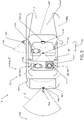
FIG. 2 is an elevational view of a vehicle comprising a display device configured to display image data including a feature of a passenger of the vehicle; -
FIG. 3 is a detailed view a display device configured to display image data including a feature of a passenger of the vehicle; -
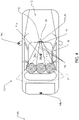
FIG. 4 is an elevational view of the display system ofFIG. 3 further demonstrating a sound detecting embodiment of the display device; and -
FIG. 5 is a block diagram of a display system in accordance with the disclosure. - The present illustrated embodiments reside primarily in combinations of method steps and apparatus components related to an image sensor system and method thereof. Accordingly, the apparatus components and method steps have been represented, where appropriate, by conventional symbols in the drawings, showing only those specific details that are pertinent to understanding the embodiments of the present disclosure so as not to obscure the disclosure with details that will be readily apparent to those of ordinary skill in the art having the benefit of the description herein. Further, like numerals in the description and drawings represent like elements.
- In this document, relational terms, such as first and second, top and bottom, and the like, are used solely to distinguish one entity or action from another entity or action, without necessarily requiring or implying any actual such relationship or order between such entities or actions. The terms "comprises," "comprising," or any other variation thereof, are intended to cover a non-exclusive inclusion, such that a process, method, article, or apparatus that comprises a list of elements does not include only those elements but may include other elements not expressly listed or inherent to such process, method, article, or apparatus.
- Referring to
FIGS. 1 ,2 , and3 , avehicle 10 is shown equipped with adisplay system 12. In various embodiments, thedisplay system 12 comprises at least oneimager 14. Theimager 14 corresponds to a plurality ofimagers 14. The plurality ofimagers 14 includes afirst imager 14a configured to capture afirst image data 16a corresponding to an interior field ofview 17 of apassenger compartment 18 of thevehicle 10. The plurality ofimagers 14 further comprises asecond imager 14b configured to capture asecond image data 16b corresponding to a scene directed to anexterior region 20 proximate thevehicle 10. In an exemplary embodiment,exterior region 20 corresponds to a rearward directed field ofview 21 relative to aforward direction 22 of thevehicle 10. - The
image data imager 14 are displayed by thedisplay system 12 on adisplay device 24. In some embodiments, thedisplay device 24 corresponds to arearview display device 26 configured to demonstrate thesecond image data 16b of the rearward directedview 21. In this configuration, thedisplay system 12 may be operable to display a series of images captured corresponding to scenes behind thevehicle 10. The scenes may include one or more objects, landscapes, road features, and any other visual information that may be captured by thesecond imager 14b. Theimagers 14 as discussed herein are in communication with a controller and may comprise pixel arrays configured to capture theimage data 16 in the form of pixel information. In the various implementations discussed herein, thedisplay system 12 is configured to process theimage data 16 captured by one or more of theimagers 14 and display afeature 28 or portion of one or more objects 30 identified in theimage data 16. - In an exemplary embodiment, the
display system 12 is configured to display theimage data 16a on afirst portion 32a of display screen 32 of thedisplay device 24. Additionally, thedisplay system 12 is configured to display thesecond image data 16b on a second portion 32b of a display screen 32. Thefirst image data 16a may be superimposed over or divided in a separate display window over thesecond image data 16b similar to a picture-in-picture display. As discussed previously, thefirst image data 16a corresponds to a scene inside thepassenger compartment 18, and thesecond image data 16b corresponds to a scene of theexterior region 20. During operation, thesecond image data 16b is displayed on the second portion 32b to provide rearview operational information configured to assist an operator orpassenger 34 of thevehicle 10 in viewing the rearward directed field ofview 21. - The
first image data 16a and/or thesecond image data 16b is displayed selectively on the display screen 32 throughout operation of thevehicle 10. Additionally, in some embodiments, thefirst image data 16a and/or thesecond image data 16b may be selectively displayed on the display screen 32 in response to one or more of a detection of a feature or identification of an event in theimage data 16. Theimage data 16a and/or 16b is selectively displayed in response to one or more input signals or operating conditions of thevehicle 10. Thedisplay system 12 may comprise acontroller 40 configured to identify the feature or the event in theimage data 16. Additionally, thecontroller 40 is configured to selectively display theimage data 16a and/or 16b in response to the one or more input signals or operating conditions of thevehicle 10. In this configuration, thedisplay system 12 may provide for a flexible solution that may be utilized to displayimage data 16 for a variety of diverse applications. Thecontroller 40 is further discussed in reference toFIG. 5 . - In some embodiments, the
controller 40 may comprise one or more processors and/or control circuits configured to process theimage data 16 received from thefirst imager 14a and/or thesecond imager 14b. For example, in some embodiments, thecontroller 40 processes thefirst image data 16a from thefirst imager 14a to identify a display-prompt (e.g., a gesture, motion, speech, or other form of input or stimulus) of apassenger 34 of thevehicle 10. In response to detecting the display-prompt of thepassenger 34, thecontroller 40 controls thedisplay system 12 to display a portion of interest of thepassenger 34 in adisplay window 42 on the display screen 32. The portion of interest corresponds to afacial region 44 of thepassenger 34 that may be cropped and/or otherwise processed for display in thedisplay window 42. In this configuration, thedisplay system 12 is configured to selectively display the portion of interest of theimage data 16a in response to thecontroller 40 identifying the display-prompt. Though described as a gesture, motion, or speech, the display-prompt may correspond to various inputs or stimuli received by thecontroller 40. Accordingly, thedisplay system 12 may be configured to provide a variety of display functions based on various inputs identified or received by thecontroller 40. - In some embodiments, the
controller 40 may be operable to crop theimage data 16a focusing on the region of interest. The region of interest may be identified by thecontroller 40 based on a facial recognition process applied to theimage data 16a thereby identifying afacial region 44 of thepassenger 34 or occupant. The identifiedfacial region 44 may then be cropped by thecontroller 40 to generate croppedimage data 16a focusing on thefacial region 44 of the occupant. In this way, thecontroller 40 is operable to demonstrate the relevant information in thedisplay window 42 and limit the display of additional information that may not relate to a communication from thepassenger 34. - As discussed herein, a
passenger 34 may correspond to a person (e.g., adults, children), an animal (e.g., a pet), and/or any object of interest in thepassenger compartment 18. Theimagers 14 discussed herein are demonstrated in fixed locations in connection with thevehicle 10. However, in some embodiments, theimagers 14 may be flexibly utilized in various portions of thevehicle 10. In such embodiments, one or more of theimagers 14 may be configured to communicate wirelessly (e.g., via Bluetooth™, WiFi™, ZigBee®, etc.) with thecontroller 40. In this configuration, one or more of theimagers 14 may be selectively positioned in connection with thevehicle 10 such that thecontroller 40 may detect a display-prompt corresponding to motion of objects positioned in a field of view. - In some embodiments, the at least one
imager 14 may comprise athird imager 14c. Though designated with the term, third, thethird imager 14c may correspond to the at least oneimager 14 or may be utilized in any combination with thefirst imager 14a and/or thesecond imager 14b. In an exemplary embodiment, thethird imager 14c may be configured to communicate wirelessly with thecontroller 40 and be selectively positioned to capture image data of a selectable field ofview 45. The selectable field ofview 45 may be selected to include one or more objects ofinterest 47. Thecontroller 40 may be configured to detect motion of the one or more objects 30 of interest in image data received from thethird imager 14c. The motion of the one or more objects 30 of interest in the image data may be detected by thecontroller 40 to identify the display-prompt. In response to the display-prompt, thecontroller 40 may selectively display one or more of the objects 30 of interest in thedisplay window 42. - An object of interest as described herein may refer to any object, scene, or region captured in a field of view of the
imager 14. For example, an object of interest may correspond to atrailer hitch 46a, aluggage compartment 46b, afuel door 46c, anengine 46d, awheel 46e, anunderbody component 46f, ablind spot 46g, or any portion of thevehicle 10. In some embodiments, the object of interest may correspond to a region ofinterest 47 that may be monitored for motion of an object that may enter theregion 47. For example, in some embodiments, thethird imager 14c may be configured to capture image data corresponding to ablind spot 46g of thevehicle 10. In this configuration, thecontroller 40 may selectively display an object (e.g., a nearby vehicle) entering the region ofinterest 47 in response to a detection of motion of the object in the region ofinterest 47. - Though discussed as having a modular or portable wireless design configured to be selectively located or positioned on the
vehicle 10, thethird imager 14c may be located in a fixed position in connection with thevehicle 10. Additionally, thefirst imager 14a and/or thesecond imager 14b may be configured to communicate theimage data 16 to thecontroller 40 wirelessly. Accordingly, theimager 14 may be utilized in a variety of applications to display information corresponding to various portions of thevehicle 10. Further details regarding theimagers 14 andcontroller 40 are discussed in reference toFIG. 5 . - Still referring to
FIGS. 2 and3 , thecontroller 40 may be configured to identify the display-prompt as a motion of a facial feature 46 (e.g., a mouth, jaw, eye, etc.) that may correspond to speech of thepassenger 34. In response to the detection of the display-prompt in theimage data 16a, thecontroller 40 displays thefacial region 44 of thepassenger 34 on thedisplay device 24. Thecontroller 40 may continue to detect movement of the one or morefacial features 46 and display thefacial region 44 in thedisplay window 42 until the motion offacial features 46 is not detected for a predetermined period of time. For example, thecontroller 40 may terminate the display of theimage data 16a of thefacial region 44 of thepassenger 34 on thedisplay device 24 after a predetermined period of time elapses following the completion of the speech of the occupant. In this way, thecontroller 40 may selectively display thefacial region 44 and thedisplay window 42 during temporal periods during which thepassenger 34 may be moving or speaking. - The motion detected by the
controller 40 corresponding to the display-prompt may correspond to a detected motion of one or more of thefacial features 46 exceeding a motion threshold. Thecontroller 40 may identify that the detected motion has exceeded the motion threshold by identifying motion of pixel data corresponding to the one or morefacial features 46 moving in excess of a predetermined distance over a plurality of consecutive frames captured by thefirst imager 14a. Such an identification of the one or morefacial features 46 may result in thecontroller 40 triggering the display-prompt and display thefacial region 44 of thepassenger 34 in thedisplay window 42 for a predetermined period of time. - Once the
facial region 44 is displayed on thedisplay device 24, thecontroller 40 may continue to process thefirst image data 16a to determine if the one or morefacial features 46 continue to move in excess of the motion threshold. Thecontroller 40 may continue to display thefacial region 44 of thefirst image data 16a in thedisplay window 42 for a predetermined period of time (e.g., 2 seconds, 5 seconds, etc.). If thecontroller 40 detects the motion of the one or morefacial features 46 exceeding the motion threshold, thecontroller 40 may reset the predetermined period of time and continue to display thefacial region 44 in thedisplay window 42. Thecontroller 40 may continue to display thefacial region 44 until the predetermined period of time expires without the motion threshold being exceeded. In this way, thecontroller 40 may display thefacial region 44 in thedisplay window 42 while thepassenger 34 is speaking. - Referring now to
FIG. 4 , in some embodiments, thecontroller 40 comprisesmicrophones 52 that are configured to detect speech or noise corresponding to thepassengers 34 of thevehicle 10. The detection of such speech is also utilized by thecontroller 40 as a display-prompt. The one ormore microphones 52 correspond to a microphone array operable to detect a region in thepassenger compartment 18 from which the noise or speech originated. For example, thecontroller 40 is configured to receive an audio signal from the one ormore microphones 52. Based on the audio signal, thecontroller 40 identifies whether a noise in the audio signal originated in one of a plurality ofregions 54 of thepassenger compartment 18. For example, thecontroller 40 is operable to distinguish if the noise originated in afirst region 54a, a second region 54b, or a third region 54c of thepassenger compartment 18. Thecontroller 40 then utilizes this information to activate the display of thefacial region 44 in thedisplay window 42. In some embodiments, the audio signal is utilized in combination with thefirst image data 16a to identify the display-prompt. - The one or
more microphones 52 utilize various detection methods to distinguish theregion 54 of thepassenger compartment 18 from which the noise originated. To enable such detection, the one ormore processors 64 of thecontroller 40 may comprise a digital signal processor (DSP) in communication with the one ormore microphones 52. The DSP may process the audio signals from themicrophone 52 or microphone array via beam forming, and/or polar steering to determine a particular region of the plurality ofregions 54 from which a noise originated. Further details regarding the detection of a region from which one or more noises may be detected are discussed inUnited States Patent No. 7,447,320 entitled, "Vehicle Accessory Microphone,". Accordingly, thecontroller 40 utilizes the indication of theregion 54 from which a noise in thepassenger compartment 18 originated to search thefirst image data 16a for afacial region 44 to display on thedisplay device 24. Thecontroller 40 may continue to display thefacial region 44 throughout a detection of the motion or speech originating from theregion 54. Thecontroller 40 may continue to display thefacial region 44 on thedisplay device 24 for a predetermined time as previously discussed. - The one or
more microphones 52 may be disposed in arearview assembly 56, which may correspond to thedisplay device 24. Therearview assembly 56 may be configured to operate in a mirror mode as well as a display mode. In the display mode, thedisplay device 24 may be configured to display theimage data 16 on the display screen 32. Additionally, in some embodiments, therearview assembly 56 may correspond to an electro-optic or electrochromic mirror assembly. Accordingly, the disclosure may incorporate a display screen 32 for use in an automotive vehicle that may correspond to a mirror-display as disclosed inU.S. Pat. Nos. 8,582,052 ;6,870,655 ;6,737,630 ;6,572,233 ;6,552,326 ;6,420,800 ;6,407,468 ;6,346,698 ;6,170,956 ;5,883,605 ; and5,825,527 ; andU.S. Pat. Application Publication No. 2009/0096937 A1 entitled "Vehicle Rearview Assembly Including a Display for Displaying Video Captured by a Camera and User Instructions," all commonly assigned to Gentex Corporation. - In operation, the
controller 40 is operable to detect and control one or more functions of the display device in response to a voice recognition received via the one ormore microphones 52. In this configuration,display device 24 may be configured to enable hands-free operation. The DSP of thecontroller 40 may process one of more speech signals received by the one or more microphones in various speech situations. The DSP processes the speech from a desired or identified spatial location (i.e., the location in which the driver or other passengers are located). Arrival time differences of the speech signal to a plurality of microphones may be used to narrow and filter conflicting noises. As provided by the claimed embodiment of the invention, the DSP's comprise stored information of human speech including fundamental frequencies that may be used to filter voice signals. As a result, thecontroller 40 is configured to process signals and frequencies that are likely to contain speech and identify one or more commands configured to control the operation of thedisplay device 24 or one or more systems in communication with thecontroller 40. - Though discussed in detail in reference to the
rearview assembly 56, the one ormore microphones 52 may be disposed in various portions of thevehicle 10. For example, the one ormore microphones 52 may be disposed in a headliner, a pillar, a seat, door panel, or various portions of thevehicle 10. Accordingly, themicrophone 52 may be flexibly positioned in thevehicle 10 to suit a particular application. - The disclosure provides for the
controller 40 to utilize for example the detection of motion of thefacial features 46, and at least an indication of aregion 54 from which a noise in thepassenger compartment 18 originated to identify apassenger 34 is speaking in thepassenger compartment 18. Based on the detection, thecontroller 40 identifies a display-prompt and display thefirst image data 16a of thepassenger compartment 18 in thedisplay window 42. Additionally, thecontroller 40 may display thesecond image data 16b on the display screen 32 throughout operation of thevehicle 10 and/or in response to various vehicle operating conditions. Accordingly, thedisplay system 12 may selectively display thefirst image data 16a and/or thesecond image data 16b to assist in operation of thevehicle 10. - Referring now to
FIG. 5 , a block diagram of thedisplay system 12 is shown. The imager 14 (e.g., thefirst imager 14a and/or thesecond imager 14b) is shown in communication with thecontroller 40. A pixel array of theimagers 14 may correspond to a complementary metal-oxide semiconductor (CMOS) image sensor, for example, a CMOS active-pixel sensor (APS) or a charge coupled device (CCD). Each of the pixels of the pixel array may correspond to a photo-sensor, an array of photo-sensors, or any grouping of sensors configured to capture light. Thecontroller 40 may comprise aprocessor 64 operable to process the image data as supplied in analog or digital form from the imager(s) 14. In various embodiments, theprocessor 64 may be implemented as a plurality of processors, a multicore processor, or any combination of processors, circuits, and peripheral processing devices. - In some embodiments, one or more of the
imagers 14 may correspond to infrared imaging devices. Such devices may comprise lighting modules configured to project infrared radiation. For example, thesecond imager 14b may correspond to an infrared imaging device. In such an embodiment, thecontroller 40 may be configured to receive infrared image data corresponding to one or more of thepassengers 34 of thevehicle 10. In this configuration, thecontroller 40 may utilize the infrared image data to identify thepassenger 34 based on a retinal identification or various identification algorithms. - The
controller 40 may further comprise amemory 66. Thememory 66 may comprise various forms of memory, for example, random access memory (RAM), dynamic RAM (DRAM), synchronous (SDRAM), and other forms of memory configured to store digital information. Thememory 66 may be configured to store the image data 16 (e.g., thefirst image data 16a and/or thesecond image data 16b) for processing. Processing theimage data 16 may comprise scaling and cropping theimage data 16 to adjust a position and apparent size of theimage data 16 as it is output to the display screen 32 of thedisplay device 24. In some embodiments, thememory 66 may further be configured to store additional programming information including method and processes for operation of thedisplay system 12. - The one or
more imagers 14 may be configured to communicate with thecontroller 40 via a wired or wireless connection to suit a desired application. Some examples of wireless communication protocols may include Bluetooth™, WiFi™, ZigBee®, and similar wireless communication protocols including those yet to be developed. Accordingly, thecontroller 40 may comprise acommunication module 68 configured to communicate wirelessly with one or more of theimagers 14. In a wireless configuration, theimagers 14 may correspond to a modular configuration comprising abattery 70 as exemplified by thethird imager 14c. The modular configuration may further comprise acommunication circuit 72 configured to communicate wirelessly with thecommunication module 68 of thecontroller 40. - The
controller 40 may further be in communication with a plurality of inputs - for example, aspeed input 74, and avehicle bus 76. Thespeed input 74 may provide a signal communicating a speed of thevehicle 10 via a speedometer or any device operable to measure and communicate data corresponding to the speed of avehicle 10. Thevehicle bus 76 may be implemented using any suitable standard communication bus, such as a Controller Area Network (CAN) bus, a Local Interconnect Network (LIN) bus, etc. Thevehicle bus 76 may be configured to provide a variety of additional information to thecontroller 40. Such information may correspond to one or more vehicle states, for example, a gear selection, passenger occupancy, a headlight activation, etc., which may be utilized by thecontroller 40 to control the display of the image data. For example, thecontroller 40 may selectively display thefirst image data 16a, thesecond image data 16b, and or a third image data 16c in response to one or more vehicle states. - It will be appreciated that embodiments of the disclosure described herein may be comprised of one or more conventional processors and unique stored program instructions that control one or more processors to implement, in conjunction with certain non-processor circuits, some, most, or all of the functions of an image sensor system and method thereof, as described herein. The non-processor circuits may include, but are not limited to, signal drivers, clock circuits, power source circuits, and/or user input devices. Alternatively, some or all functions could be implemented by a state machine that has no stored program instructions, or in one or more application specific integrated circuits (ASICs), in which each function or some combinations of the functions are implemented as custom logic. Of course, a combination of the two approaches could be used. Thus, the methods and means for these functions have been described herein. Further, it is expected that one of ordinary skill, notwithstanding possibly significant effort and many design choices motivated by, for example, available time, current technology, and economic considerations, when guided by the concepts and principles disclosed herein will be readily capable of generating such software instructions and programs and ICs with minimal experimentation.
- It should be appreciated by those skilled in the art that the above described components may be combined in additional or alternative ways not explicitly described herein. Modifications of the various implementations of the disclosure will occur to those skilled in the art and to those who apply the teachings of the disclosure. Therefore, it is understood that the embodiments shown in the drawings and described above are merely for illustrative purposes and not intended to limit the scope of the disclosure, which is defined by the following claims.
Claims (4)
- A display system (12) for a vehicle (10) comprising:a rearview display device (26) being an electrochromic mirror assembly disposed in a passenger compartment (18) of the vehicle (10), the display device (26) comprising a screen (32), wherein a microphone array is disposed in the rearview display device (26), wherein the microphone array is configured to detect speech from the passenger compartment and to identify a region (54a; 54b; 54c) of the passenger compartment from where the speech of an occupant originated;a first imager (14a) configured to capture a first image data (16a) corresponding to a field of view (17) of the passenger compartment (18) of the vehicle (10);a second imager (14b) configured to capture a second image data (16b) corresponding to a rearward directed field of view (21) from the vehicle (10); anda controller (40) configured to:display the second image data (16b) on a second portion (32b) of the screen (32); anddetect a display prompt based on detected speech, wherein the display prompt comprises the detected speech of an occupant in the passenger compartment;determine a particular region (54a; 54b; 54c) which the speech originated, wherein the speech is identified by processing frequencies likely to contain human speech; andselectively display a facial region (44) comprising a facial feature (46) from the first image data (16a) on a first portion (32a) of the screen (32) in response to a detection of the display prompt, the facial region being from the determined particular region.
- The display system (12) according to claim 1, wherein the controller is further configured to:
continue to display the facial region (44) on the first portion (32a) until the speech of the occupant is no longer detected for a predetermined period of time. - The display system (12) according to any one of claims 1-2, wherein the first portion (32a) of the screen (32) corresponds to a display window (42) superimposed over the second portion (32b).
- The display system (12) according to any one of claims 1-3, wherein the controller (40) is further configured to:
identify and crop the facial region (44) of the occupant in the first image data (16a).
Applications Claiming Priority (2)
| Application Number | Priority Date | Filing Date | Title |
|---|---|---|---|
| US201662340697P | 2016-05-24 | 2016-05-24 | |
| PCT/US2017/034228 WO2017205490A1 (en) | 2016-05-24 | 2017-05-24 | Vehicle display with selective image data display |
Publications (3)
| Publication Number | Publication Date |
|---|---|
| EP3463982A1 EP3463982A1 (en) | 2019-04-10 |
| EP3463982A4 EP3463982A4 (en) | 2019-05-15 |
| EP3463982B1 true EP3463982B1 (en) | 2022-09-14 |
Family
ID=60411848
Family Applications (1)
| Application Number | Title | Priority Date | Filing Date |
|---|---|---|---|
| EP17803498.9A Active EP3463982B1 (en) | 2016-05-24 | 2017-05-24 | Vehicle display with selective image data display |
Country Status (6)
| Country | Link |
|---|---|
| US (1) | US20170347067A1 (en) |
| EP (1) | EP3463982B1 (en) |
| JP (1) | JP6839722B2 (en) |
| KR (1) | KR20190009801A (en) |
| CN (1) | CN109153353B (en) |
| WO (1) | WO2017205490A1 (en) |
Families Citing this family (12)
| Publication number | Priority date | Publication date | Assignee | Title |
|---|---|---|---|---|
| JP6665819B2 (en) * | 2017-03-17 | 2020-03-13 | トヨタ自動車株式会社 | In-vehicle display device |
| US10609339B2 (en) * | 2017-03-22 | 2020-03-31 | GM Global Technology Operations LLC | System for and method of dynamically displaying images on a vehicle electronic display |
| US10596970B2 (en) * | 2017-08-25 | 2020-03-24 | Panasonic Automotive Systems Company Of America, Division Of Panasonic Corporation Of North America | Auto-switch display intelligent rearview mirror system |
| CN216331768U (en) * | 2019-10-23 | 2022-04-19 | 索尼公司 | Display system, display device, and mobile device |
| DE102020133448A1 (en) * | 2020-12-15 | 2022-06-15 | Dr. Ing. H.C. F. Porsche Aktiengesellschaft | vehicle |
| JP7683145B2 (en) * | 2021-08-03 | 2025-05-27 | アルプスアルパイン株式会社 | Display control device and display control method |
| US12250448B2 (en) * | 2021-09-30 | 2025-03-11 | Gentex Corporation | Intelligent video conference cropping based on audio and vision |
| US20230339366A1 (en) * | 2022-04-20 | 2023-10-26 | Aptiv Technologies Limited | In-Vehicle Occupant Monitoring and Calming System |
| DE102022116811A1 (en) * | 2022-07-06 | 2024-01-11 | Bayerische Motoren Werke Aktiengesellschaft | APPARATUS, MOBILE DEVICE AND METHOD FOR CREATING AND DISPLAYING A PICTURE-IN-PICTURE |
| JPWO2024090094A1 (en) * | 2022-10-27 | 2024-05-02 | ||
| JP2024112036A (en) * | 2023-02-07 | 2024-08-20 | 株式会社Jvcケンウッド | Digital mirror device, control program |
| US20240294124A1 (en) * | 2023-03-03 | 2024-09-05 | Kodiak Robotics, Inc. | Sensor pod with user interface |
Family Cites Families (33)
| Publication number | Priority date | Publication date | Assignee | Title |
|---|---|---|---|---|
| US5883605A (en) | 1992-02-25 | 1999-03-16 | Gentex Corporation | Automatic electrochromic control of light level of vacuum fluorescent display |
| US5825527A (en) | 1997-04-02 | 1998-10-20 | Gentex Corporation | Information display area on electrochromic mirrors having a third surface metal reflector |
| US6690268B2 (en) * | 2000-03-02 | 2004-02-10 | Donnelly Corporation | Video mirror systems incorporating an accessory module |
| US6170956B1 (en) | 1998-10-14 | 2001-01-09 | Gentex Corporation | Rearview mirror with display |
| US6346698B1 (en) | 1999-07-22 | 2002-02-12 | Gentex Corporation | Low EMI multiplexed dual display |
| US7447320B2 (en) | 2001-02-14 | 2008-11-04 | Gentex Corporation | Vehicle accessory microphone |
| US6420800B1 (en) | 2000-05-25 | 2002-07-16 | Gentex Corporation | Rearview mirror with buttons incorporating display |
| US6407468B1 (en) | 2000-05-25 | 2002-06-18 | Gentex Corporation | Rearview mirror with buttons incorporating display |
| US7039199B2 (en) * | 2002-08-26 | 2006-05-02 | Microsoft Corporation | System and process for locating a speaker using 360 degree sound source localization |
| US7253723B2 (en) * | 2003-05-19 | 2007-08-07 | Donnelly Corporation | Mirror assembly |
| JP4356663B2 (en) * | 2005-08-17 | 2009-11-04 | ソニー株式会社 | Camera control device and electronic conference system |
| JP2007168670A (en) * | 2005-12-22 | 2007-07-05 | Fujitsu Ten Ltd | On-vehicle display device |
| JP2008042390A (en) * | 2006-08-03 | 2008-02-21 | National Univ Corp Shizuoka Univ | In-car conversation support system |
| WO2009026223A2 (en) | 2007-08-16 | 2009-02-26 | Gentex Corporation | Vehicle rearview assembly including a display for displaying video captured by a camera and user instructions |
| JP2009083791A (en) * | 2007-10-02 | 2009-04-23 | Auto Network Gijutsu Kenkyusho:Kk | Image display method, in-vehicle image display system, and image processing apparatus |
| US8582052B2 (en) | 2008-08-22 | 2013-11-12 | Gentex Corporation | Discrete LED backlight control for a reduced power LCD display system |
| BRPI0902877B1 (en) * | 2009-08-14 | 2019-07-02 | Metagal Indústria E Comércio Ltda | INTERNAL REAR MIRROR SYSTEM FOR AUTOMOTIVE VEHICLES |
| JP2011116219A (en) * | 2009-12-02 | 2011-06-16 | Koito Mfg Co Ltd | In-vehicle monitoring system |
| CN102647578B (en) * | 2011-02-17 | 2014-08-13 | 鸿富锦精密工业(深圳)有限公司 | Video switching system and method |
| US8903130B1 (en) * | 2011-05-09 | 2014-12-02 | Google Inc. | Virtual camera operator |
| JP5820635B2 (en) * | 2011-06-27 | 2015-11-24 | オリンパス株式会社 | Imaging device and external device communicating with the imaging device, camera system including imaging device and external device, imaging control method and imaging control program for imaging device, imaging control method and imaging control program for external device |
| US9215429B2 (en) * | 2011-10-31 | 2015-12-15 | Rosco, Inc. | Mirror monitor using two levels of reflectivity |
| US9106789B1 (en) * | 2012-01-20 | 2015-08-11 | Tech Friends, Inc. | Videoconference and video visitation security |
| CN202608663U (en) * | 2012-03-04 | 2012-12-19 | 任晔 | Improved automobile rearview mirror |
| US9288435B2 (en) * | 2013-03-27 | 2016-03-15 | Google Inc. | Speaker switching delay for video conferencing |
| JP6364702B2 (en) * | 2013-03-29 | 2018-08-01 | アイシン精機株式会社 | Image display control device, image display system, and display unit |
| US10029621B2 (en) * | 2013-05-16 | 2018-07-24 | Ford Global Technologies, Llc | Rear view camera system using rear view mirror location |
| JP6201415B2 (en) * | 2013-05-17 | 2017-09-27 | 日産自動車株式会社 | Vehicle interior monitoring device |
| JP6497158B2 (en) * | 2014-05-16 | 2019-04-10 | 株式会社リコー | Display device, moving body |
| US9800983B2 (en) * | 2014-07-24 | 2017-10-24 | Magna Electronics Inc. | Vehicle in cabin sound processing system |
| JP2016030478A (en) * | 2014-07-28 | 2016-03-07 | ポップニート株式会社 | In-vehicle information processing device, in-vehicle information processing method, program, and camera |
| ITUB20153347A1 (en) * | 2015-09-02 | 2017-03-02 | Stefano Spattini | APPARATUS FOR VIDEOCOMMUNICATION |
| US10110851B2 (en) * | 2016-05-06 | 2018-10-23 | Avaya Inc. | System and method for dynamic light adjustment in video capture |
-
2017
- 2017-05-24 CN CN201780030550.XA patent/CN109153353B/en active Active
- 2017-05-24 EP EP17803498.9A patent/EP3463982B1/en active Active
- 2017-05-24 KR KR1020187037121A patent/KR20190009801A/en not_active Ceased
- 2017-05-24 US US15/603,509 patent/US20170347067A1/en not_active Abandoned
- 2017-05-24 WO PCT/US2017/034228 patent/WO2017205490A1/en not_active Ceased
- 2017-05-24 JP JP2018560472A patent/JP6839722B2/en active Active
Also Published As
| Publication number | Publication date |
|---|---|
| US20170347067A1 (en) | 2017-11-30 |
| CN109153353A (en) | 2019-01-04 |
| JP2019523726A (en) | 2019-08-29 |
| KR20190009801A (en) | 2019-01-29 |
| EP3463982A4 (en) | 2019-05-15 |
| JP6839722B2 (en) | 2021-03-10 |
| CN109153353B (en) | 2022-04-08 |
| EP3463982A1 (en) | 2019-04-10 |
| WO2017205490A1 (en) | 2017-11-30 |
Similar Documents
| Publication | Publication Date | Title |
|---|---|---|
| US20170347067A1 (en) | Vehicle display with selective image data display | |
| US12250448B2 (en) | Intelligent video conference cropping based on audio and vision | |
| US8823796B2 (en) | Adaptive surrounding view monitoring apparatus and method thereof | |
| US12134316B2 (en) | State detection device, state detection system, and state detection method | |
| US20100201507A1 (en) | Dual-mode vision system for vehicle safety | |
| US11710291B2 (en) | Image recognition device and image recognition method | |
| US20170334357A1 (en) | Vehicle occupant viewing systems and methods | |
| JP2008213649A (en) | Vehicle periphery monitoring device | |
| JP2006193057A (en) | Vehicle monitoring unit and room mirror apparatus | |
| US11375136B2 (en) | Imaging device for high-speed read out, method of driving the same, and electronic instrument | |
| JP2018078420A (en) | Vehicle image display device and vehicle image display program | |
| TWI842952B (en) | Camera | |
| WO2017175492A1 (en) | Image processing device, image processing method, computer program and electronic apparatus | |
| JP2018191248A (en) | Imaging device, imaging method, and program | |
| US20180270406A1 (en) | Dual display reverse camera system | |
| KR102632361B1 (en) | System for providing around view image | |
| JP2016030478A (en) | In-vehicle information processing device, in-vehicle information processing method, program, and camera | |
| US20190191119A1 (en) | Imaging device and control method | |
| US12088927B2 (en) | Imaging device and imaging method | |
| JP2010118767A (en) | Image processor and image processing method | |
| TWM479253U (en) | Vehicle image safety system | |
| CN116263987A (en) | Method for capturing images in a vehicle interior and vehicle interior camera system | |
| KR20170001984A (en) | Rear view monitoring system for vehicle |
Legal Events
| Date | Code | Title | Description |
|---|---|---|---|
| STAA | Information on the status of an ep patent application or granted ep patent |
Free format text: STATUS: THE INTERNATIONAL PUBLICATION HAS BEEN MADE |
|
| PUAI | Public reference made under article 153(3) epc to a published international application that has entered the european phase |
Free format text: ORIGINAL CODE: 0009012 |
|
| STAA | Information on the status of an ep patent application or granted ep patent |
Free format text: STATUS: REQUEST FOR EXAMINATION WAS MADE |
|
| 17P | Request for examination filed |
Effective date: 20181122 |
|
| AK | Designated contracting states |
Kind code of ref document: A1 Designated state(s): AL AT BE BG CH CY CZ DE DK EE ES FI FR GB GR HR HU IE IS IT LI LT LU LV MC MK MT NL NO PL PT RO RS SE SI SK SM TR |
|
| AX | Request for extension of the european patent |
Extension state: BA ME |
|
| REG | Reference to a national code |
Ref country code: DE Ref legal event code: R079 Ref document number: 602017061831 Country of ref document: DE Free format text: PREVIOUS MAIN CLASS: B60R0001040000 Ipc: H04N0007180000 |
|
| A4 | Supplementary search report drawn up and despatched |
Effective date: 20190416 |
|
| RIC1 | Information provided on ipc code assigned before grant |
Ipc: B60K 35/00 20060101ALI20190410BHEP Ipc: H04N 7/18 20060101AFI20190410BHEP |
|
| DAV | Request for validation of the european patent (deleted) | ||
| DAX | Request for extension of the european patent (deleted) | ||
| STAA | Information on the status of an ep patent application or granted ep patent |
Free format text: STATUS: EXAMINATION IS IN PROGRESS |
|
| 17Q | First examination report despatched |
Effective date: 20200529 |
|
| GRAP | Despatch of communication of intention to grant a patent |
Free format text: ORIGINAL CODE: EPIDOSNIGR1 |
|
| STAA | Information on the status of an ep patent application or granted ep patent |
Free format text: STATUS: GRANT OF PATENT IS INTENDED |
|
| GRAS | Grant fee paid |
Free format text: ORIGINAL CODE: EPIDOSNIGR3 |
|
| INTG | Intention to grant announced |
Effective date: 20220712 |
|
| GRAA | (expected) grant |
Free format text: ORIGINAL CODE: 0009210 |
|
| STAA | Information on the status of an ep patent application or granted ep patent |
Free format text: STATUS: THE PATENT HAS BEEN GRANTED |
|
| AK | Designated contracting states |
Kind code of ref document: B1 Designated state(s): AL AT BE BG CH CY CZ DE DK EE ES FI FR GB GR HR HU IE IS IT LI LT LU LV MC MK MT NL NO PL PT RO RS SE SI SK SM TR |
|
| REG | Reference to a national code |
Ref country code: GB Ref legal event code: FG4D |
|
| REG | Reference to a national code |
Ref country code: CH Ref legal event code: EP |
|
| REG | Reference to a national code |
Ref country code: DE Ref legal event code: R096 Ref document number: 602017061831 Country of ref document: DE |
|
| REG | Reference to a national code |
Ref country code: IE Ref legal event code: FG4D |
|
| REG | Reference to a national code |
Ref country code: AT Ref legal event code: REF Ref document number: 1519410 Country of ref document: AT Kind code of ref document: T Effective date: 20221015 |
|
| REG | Reference to a national code |
Ref country code: LT Ref legal event code: MG9D |
|
| REG | Reference to a national code |
Ref country code: NL Ref legal event code: MP Effective date: 20220914 |
|
| PG25 | Lapsed in a contracting state [announced via postgrant information from national office to epo] |
Ref country code: SE Free format text: LAPSE BECAUSE OF FAILURE TO SUBMIT A TRANSLATION OF THE DESCRIPTION OR TO PAY THE FEE WITHIN THE PRESCRIBED TIME-LIMIT Effective date: 20220914 Ref country code: RS Free format text: LAPSE BECAUSE OF FAILURE TO SUBMIT A TRANSLATION OF THE DESCRIPTION OR TO PAY THE FEE WITHIN THE PRESCRIBED TIME-LIMIT Effective date: 20220914 Ref country code: NO Free format text: LAPSE BECAUSE OF FAILURE TO SUBMIT A TRANSLATION OF THE DESCRIPTION OR TO PAY THE FEE WITHIN THE PRESCRIBED TIME-LIMIT Effective date: 20221214 Ref country code: LV Free format text: LAPSE BECAUSE OF FAILURE TO SUBMIT A TRANSLATION OF THE DESCRIPTION OR TO PAY THE FEE WITHIN THE PRESCRIBED TIME-LIMIT Effective date: 20220914 Ref country code: LT Free format text: LAPSE BECAUSE OF FAILURE TO SUBMIT A TRANSLATION OF THE DESCRIPTION OR TO PAY THE FEE WITHIN THE PRESCRIBED TIME-LIMIT Effective date: 20220914 Ref country code: FI Free format text: LAPSE BECAUSE OF FAILURE TO SUBMIT A TRANSLATION OF THE DESCRIPTION OR TO PAY THE FEE WITHIN THE PRESCRIBED TIME-LIMIT Effective date: 20220914 |
|
| REG | Reference to a national code |
Ref country code: AT Ref legal event code: MK05 Ref document number: 1519410 Country of ref document: AT Kind code of ref document: T Effective date: 20220914 |
|
| PG25 | Lapsed in a contracting state [announced via postgrant information from national office to epo] |
Ref country code: HR Free format text: LAPSE BECAUSE OF FAILURE TO SUBMIT A TRANSLATION OF THE DESCRIPTION OR TO PAY THE FEE WITHIN THE PRESCRIBED TIME-LIMIT Effective date: 20220914 Ref country code: GR Free format text: LAPSE BECAUSE OF FAILURE TO SUBMIT A TRANSLATION OF THE DESCRIPTION OR TO PAY THE FEE WITHIN THE PRESCRIBED TIME-LIMIT Effective date: 20221215 |
|
| PG25 | Lapsed in a contracting state [announced via postgrant information from national office to epo] |
Ref country code: SM Free format text: LAPSE BECAUSE OF FAILURE TO SUBMIT A TRANSLATION OF THE DESCRIPTION OR TO PAY THE FEE WITHIN THE PRESCRIBED TIME-LIMIT Effective date: 20220914 Ref country code: RO Free format text: LAPSE BECAUSE OF FAILURE TO SUBMIT A TRANSLATION OF THE DESCRIPTION OR TO PAY THE FEE WITHIN THE PRESCRIBED TIME-LIMIT Effective date: 20220914 Ref country code: PT Free format text: LAPSE BECAUSE OF FAILURE TO SUBMIT A TRANSLATION OF THE DESCRIPTION OR TO PAY THE FEE WITHIN THE PRESCRIBED TIME-LIMIT Effective date: 20230116 Ref country code: ES Free format text: LAPSE BECAUSE OF FAILURE TO SUBMIT A TRANSLATION OF THE DESCRIPTION OR TO PAY THE FEE WITHIN THE PRESCRIBED TIME-LIMIT Effective date: 20220914 Ref country code: CZ Free format text: LAPSE BECAUSE OF FAILURE TO SUBMIT A TRANSLATION OF THE DESCRIPTION OR TO PAY THE FEE WITHIN THE PRESCRIBED TIME-LIMIT Effective date: 20220914 Ref country code: AT Free format text: LAPSE BECAUSE OF FAILURE TO SUBMIT A TRANSLATION OF THE DESCRIPTION OR TO PAY THE FEE WITHIN THE PRESCRIBED TIME-LIMIT Effective date: 20220914 |
|
| PG25 | Lapsed in a contracting state [announced via postgrant information from national office to epo] |
Ref country code: SK Free format text: LAPSE BECAUSE OF FAILURE TO SUBMIT A TRANSLATION OF THE DESCRIPTION OR TO PAY THE FEE WITHIN THE PRESCRIBED TIME-LIMIT Effective date: 20220914 Ref country code: PL Free format text: LAPSE BECAUSE OF FAILURE TO SUBMIT A TRANSLATION OF THE DESCRIPTION OR TO PAY THE FEE WITHIN THE PRESCRIBED TIME-LIMIT Effective date: 20220914 Ref country code: IS Free format text: LAPSE BECAUSE OF FAILURE TO SUBMIT A TRANSLATION OF THE DESCRIPTION OR TO PAY THE FEE WITHIN THE PRESCRIBED TIME-LIMIT Effective date: 20230114 Ref country code: EE Free format text: LAPSE BECAUSE OF FAILURE TO SUBMIT A TRANSLATION OF THE DESCRIPTION OR TO PAY THE FEE WITHIN THE PRESCRIBED TIME-LIMIT Effective date: 20220914 |
|
| P01 | Opt-out of the competence of the unified patent court (upc) registered |
Effective date: 20230503 |
|
| REG | Reference to a national code |
Ref country code: DE Ref legal event code: R097 Ref document number: 602017061831 Country of ref document: DE |
|
| PG25 | Lapsed in a contracting state [announced via postgrant information from national office to epo] |
Ref country code: NL Free format text: LAPSE BECAUSE OF FAILURE TO SUBMIT A TRANSLATION OF THE DESCRIPTION OR TO PAY THE FEE WITHIN THE PRESCRIBED TIME-LIMIT Effective date: 20220914 Ref country code: AL Free format text: LAPSE BECAUSE OF FAILURE TO SUBMIT A TRANSLATION OF THE DESCRIPTION OR TO PAY THE FEE WITHIN THE PRESCRIBED TIME-LIMIT Effective date: 20220914 |
|
| PLBE | No opposition filed within time limit |
Free format text: ORIGINAL CODE: 0009261 |
|
| STAA | Information on the status of an ep patent application or granted ep patent |
Free format text: STATUS: NO OPPOSITION FILED WITHIN TIME LIMIT |
|
| PG25 | Lapsed in a contracting state [announced via postgrant information from national office to epo] |
Ref country code: DK Free format text: LAPSE BECAUSE OF FAILURE TO SUBMIT A TRANSLATION OF THE DESCRIPTION OR TO PAY THE FEE WITHIN THE PRESCRIBED TIME-LIMIT Effective date: 20220914 |
|
| 26N | No opposition filed |
Effective date: 20230615 |
|
| PG25 | Lapsed in a contracting state [announced via postgrant information from national office to epo] |
Ref country code: SI Free format text: LAPSE BECAUSE OF FAILURE TO SUBMIT A TRANSLATION OF THE DESCRIPTION OR TO PAY THE FEE WITHIN THE PRESCRIBED TIME-LIMIT Effective date: 20220914 |
|
| REG | Reference to a national code |
Ref country code: CH Ref legal event code: PL |
|
| PG25 | Lapsed in a contracting state [announced via postgrant information from national office to epo] |
Ref country code: MC Free format text: LAPSE BECAUSE OF FAILURE TO SUBMIT A TRANSLATION OF THE DESCRIPTION OR TO PAY THE FEE WITHIN THE PRESCRIBED TIME-LIMIT Effective date: 20220914 |
|
| REG | Reference to a national code |
Ref country code: BE Ref legal event code: MM Effective date: 20230531 |
|
| PG25 | Lapsed in a contracting state [announced via postgrant information from national office to epo] |
Ref country code: MC Free format text: LAPSE BECAUSE OF FAILURE TO SUBMIT A TRANSLATION OF THE DESCRIPTION OR TO PAY THE FEE WITHIN THE PRESCRIBED TIME-LIMIT Effective date: 20220914 Ref country code: LU Free format text: LAPSE BECAUSE OF NON-PAYMENT OF DUE FEES Effective date: 20230524 Ref country code: LI Free format text: LAPSE BECAUSE OF NON-PAYMENT OF DUE FEES Effective date: 20230531 Ref country code: CH Free format text: LAPSE BECAUSE OF NON-PAYMENT OF DUE FEES Effective date: 20230531 |
|
| REG | Reference to a national code |
Ref country code: IE Ref legal event code: MM4A |
|
| PG25 | Lapsed in a contracting state [announced via postgrant information from national office to epo] |
Ref country code: IE Free format text: LAPSE BECAUSE OF NON-PAYMENT OF DUE FEES Effective date: 20230524 |
|
| PG25 | Lapsed in a contracting state [announced via postgrant information from national office to epo] |
Ref country code: IE Free format text: LAPSE BECAUSE OF NON-PAYMENT OF DUE FEES Effective date: 20230524 |
|
| PG25 | Lapsed in a contracting state [announced via postgrant information from national office to epo] |
Ref country code: IT Free format text: LAPSE BECAUSE OF FAILURE TO SUBMIT A TRANSLATION OF THE DESCRIPTION OR TO PAY THE FEE WITHIN THE PRESCRIBED TIME-LIMIT Effective date: 20220914 Ref country code: BE Free format text: LAPSE BECAUSE OF NON-PAYMENT OF DUE FEES Effective date: 20230531 |
|
| PG25 | Lapsed in a contracting state [announced via postgrant information from national office to epo] |
Ref country code: BG Free format text: LAPSE BECAUSE OF FAILURE TO SUBMIT A TRANSLATION OF THE DESCRIPTION OR TO PAY THE FEE WITHIN THE PRESCRIBED TIME-LIMIT Effective date: 20220914 |
|
| PG25 | Lapsed in a contracting state [announced via postgrant information from national office to epo] |
Ref country code: BG Free format text: LAPSE BECAUSE OF FAILURE TO SUBMIT A TRANSLATION OF THE DESCRIPTION OR TO PAY THE FEE WITHIN THE PRESCRIBED TIME-LIMIT Effective date: 20220914 |
|
| PGFP | Annual fee paid to national office [announced via postgrant information from national office to epo] |
Ref country code: DE Payment date: 20250423 Year of fee payment: 9 |
|
| PGFP | Annual fee paid to national office [announced via postgrant information from national office to epo] |
Ref country code: GB Payment date: 20250423 Year of fee payment: 9 |
|
| PGFP | Annual fee paid to national office [announced via postgrant information from national office to epo] |
Ref country code: FR Payment date: 20250423 Year of fee payment: 9 |
|
| PG25 | Lapsed in a contracting state [announced via postgrant information from national office to epo] |
Ref country code: CY Free format text: LAPSE BECAUSE OF FAILURE TO SUBMIT A TRANSLATION OF THE DESCRIPTION OR TO PAY THE FEE WITHIN THE PRESCRIBED TIME-LIMIT; INVALID AB INITIO Effective date: 20170524 |
|
| PG25 | Lapsed in a contracting state [announced via postgrant information from national office to epo] |
Ref country code: HU Free format text: LAPSE BECAUSE OF FAILURE TO SUBMIT A TRANSLATION OF THE DESCRIPTION OR TO PAY THE FEE WITHIN THE PRESCRIBED TIME-LIMIT; INVALID AB INITIO Effective date: 20170524 |
|
| PG25 | Lapsed in a contracting state [announced via postgrant information from national office to epo] |
Ref country code: TR Free format text: LAPSE BECAUSE OF FAILURE TO SUBMIT A TRANSLATION OF THE DESCRIPTION OR TO PAY THE FEE WITHIN THE PRESCRIBED TIME-LIMIT Effective date: 20220914 |