EP3463976B1 - Selbstangetriebenes modul für übergrosse lasten - Google Patents
Selbstangetriebenes modul für übergrosse lasten Download PDFInfo
- Publication number
- EP3463976B1 EP3463976B1 EP17728792.7A EP17728792A EP3463976B1 EP 3463976 B1 EP3463976 B1 EP 3463976B1 EP 17728792 A EP17728792 A EP 17728792A EP 3463976 B1 EP3463976 B1 EP 3463976B1
- Authority
- EP
- European Patent Office
- Prior art keywords
- self
- oil
- module according
- load
- propelled module
- Prior art date
- Legal status (The legal status is an assumption and is not a legal conclusion. Google has not performed a legal analysis and makes no representation as to the accuracy of the status listed.)
- Active
Links
Images



Classifications
-
- B—PERFORMING OPERATIONS; TRANSPORTING
- B60—VEHICLES IN GENERAL
- B60P—VEHICLES ADAPTED FOR LOAD TRANSPORTATION OR TO TRANSPORT, TO CARRY, OR TO COMPRISE SPECIAL LOADS OR OBJECTS
- B60P3/00—Vehicles adapted to transport, to carry or to comprise special loads or objects
- B60P3/40—Vehicles adapted to transport, to carry or to comprise special loads or objects for carrying long loads, e.g. with separate wheeled load supporting elements
-
- B—PERFORMING OPERATIONS; TRANSPORTING
- B26—HAND CUTTING TOOLS; CUTTING; SEVERING
- B26D—CUTTING; DETAILS COMMON TO MACHINES FOR PERFORATING, PUNCHING, CUTTING-OUT, STAMPING-OUT OR SEVERING
- B26D1/00—Cutting through work characterised by the nature or movement of the cutting member or particular materials not otherwise provided for; Apparatus or machines therefor; Cutting members therefor
- B26D1/01—Cutting through work characterised by the nature or movement of the cutting member or particular materials not otherwise provided for; Apparatus or machines therefor; Cutting members therefor involving a cutting member which does not travel with the work
- B26D1/12—Cutting through work characterised by the nature or movement of the cutting member or particular materials not otherwise provided for; Apparatus or machines therefor; Cutting members therefor involving a cutting member which does not travel with the work having a cutting member moving about an axis
- B26D1/14—Cutting through work characterised by the nature or movement of the cutting member or particular materials not otherwise provided for; Apparatus or machines therefor; Cutting members therefor involving a cutting member which does not travel with the work having a cutting member moving about an axis with a circular cutting member, e.g. disc cutter
- B26D1/24—Cutting through work characterised by the nature or movement of the cutting member or particular materials not otherwise provided for; Apparatus or machines therefor; Cutting members therefor involving a cutting member which does not travel with the work having a cutting member moving about an axis with a circular cutting member, e.g. disc cutter coacting with another disc cutter
- B26D1/245—Cutting through work characterised by the nature or movement of the cutting member or particular materials not otherwise provided for; Apparatus or machines therefor; Cutting members therefor involving a cutting member which does not travel with the work having a cutting member moving about an axis with a circular cutting member, e.g. disc cutter coacting with another disc cutter for thin material, e.g. for sheets, strips or the like
-
- B—PERFORMING OPERATIONS; TRANSPORTING
- B32—LAYERED PRODUCTS
- B32B—LAYERED PRODUCTS, i.e. PRODUCTS BUILT-UP OF STRATA OF FLAT OR NON-FLAT, e.g. CELLULAR OR HONEYCOMB, FORM
- B32B37/00—Methods or apparatus for laminating, e.g. by curing or by ultrasonic bonding
- B32B37/12—Methods or apparatus for laminating, e.g. by curing or by ultrasonic bonding characterised by using adhesives
-
- B—PERFORMING OPERATIONS; TRANSPORTING
- B32—LAYERED PRODUCTS
- B32B—LAYERED PRODUCTS, i.e. PRODUCTS BUILT-UP OF STRATA OF FLAT OR NON-FLAT, e.g. CELLULAR OR HONEYCOMB, FORM
- B32B38/00—Ancillary operations in connection with laminating processes
- B32B38/14—Printing or colouring
- B32B38/145—Printing
-
- B—PERFORMING OPERATIONS; TRANSPORTING
- B32—LAYERED PRODUCTS
- B32B—LAYERED PRODUCTS, i.e. PRODUCTS BUILT-UP OF STRATA OF FLAT OR NON-FLAT, e.g. CELLULAR OR HONEYCOMB, FORM
- B32B39/00—Layout of apparatus or plants, e.g. modular laminating systems
-
- B—PERFORMING OPERATIONS; TRANSPORTING
- B41—PRINTING; LINING MACHINES; TYPEWRITERS; STAMPS
- B41F—PRINTING MACHINES OR PRESSES
- B41F19/00—Apparatus or machines for carrying out printing operations combined with other operations
- B41F19/002—Apparatus or machines for carrying out printing operations combined with other operations with means for applying specific material other than ink
- B41F19/004—Apparatus or machines for carrying out printing operations combined with other operations with means for applying specific material other than ink with means for applying adhesive
-
- B—PERFORMING OPERATIONS; TRANSPORTING
- B41—PRINTING; LINING MACHINES; TYPEWRITERS; STAMPS
- B41F—PRINTING MACHINES OR PRESSES
- B41F5/00—Rotary letterpress machines
- B41F5/24—Rotary letterpress machines for flexographic printing
-
- B—PERFORMING OPERATIONS; TRANSPORTING
- B60—VEHICLES IN GENERAL
- B60P—VEHICLES ADAPTED FOR LOAD TRANSPORTATION OR TO TRANSPORT, TO CARRY, OR TO COMPRISE SPECIAL LOADS OR OBJECTS
- B60P1/00—Vehicles predominantly for transporting loads and modified to facilitate loading, consolidating the load, or unloading
-
- B—PERFORMING OPERATIONS; TRANSPORTING
- B65—CONVEYING; PACKING; STORING; HANDLING THIN OR FILAMENTARY MATERIAL
- B65H—HANDLING THIN OR FILAMENTARY MATERIAL, e.g. SHEETS, WEBS, CABLES
- B65H35/00—Delivering articles from cutting or line-perforating machines; Article or web delivery apparatus incorporating cutting or line-perforating devices, e.g. adhesive tape dispensers
- B65H35/02—Delivering articles from cutting or line-perforating machines; Article or web delivery apparatus incorporating cutting or line-perforating devices, e.g. adhesive tape dispensers from or with longitudinal slitters or perforators
-
- B—PERFORMING OPERATIONS; TRANSPORTING
- B65—CONVEYING; PACKING; STORING; HANDLING THIN OR FILAMENTARY MATERIAL
- B65H—HANDLING THIN OR FILAMENTARY MATERIAL, e.g. SHEETS, WEBS, CABLES
- B65H35/00—Delivering articles from cutting or line-perforating machines; Article or web delivery apparatus incorporating cutting or line-perforating devices, e.g. adhesive tape dispensers
- B65H35/04—Delivering articles from cutting or line-perforating machines; Article or web delivery apparatus incorporating cutting or line-perforating devices, e.g. adhesive tape dispensers from or with transverse cutters or perforators
- B65H35/08—Delivering articles from cutting or line-perforating machines; Article or web delivery apparatus incorporating cutting or line-perforating devices, e.g. adhesive tape dispensers from or with transverse cutters or perforators from or with revolving, e.g. cylinder, cutters or perforators
-
- B—PERFORMING OPERATIONS; TRANSPORTING
- B32—LAYERED PRODUCTS
- B32B—LAYERED PRODUCTS, i.e. PRODUCTS BUILT-UP OF STRATA OF FLAT OR NON-FLAT, e.g. CELLULAR OR HONEYCOMB, FORM
- B32B37/00—Methods or apparatus for laminating, e.g. by curing or by ultrasonic bonding
- B32B37/12—Methods or apparatus for laminating, e.g. by curing or by ultrasonic bonding characterised by using adhesives
- B32B2037/1253—Methods or apparatus for laminating, e.g. by curing or by ultrasonic bonding characterised by using adhesives curable adhesive
-
- B—PERFORMING OPERATIONS; TRANSPORTING
- B32—LAYERED PRODUCTS
- B32B—LAYERED PRODUCTS, i.e. PRODUCTS BUILT-UP OF STRATA OF FLAT OR NON-FLAT, e.g. CELLULAR OR HONEYCOMB, FORM
- B32B2310/00—Treatment by energy or chemical effects
- B32B2310/08—Treatment by energy or chemical effects by wave energy or particle radiation
- B32B2310/0875—Treatment by energy or chemical effects by wave energy or particle radiation using particle radiation
- B32B2310/0887—Treatment by energy or chemical effects by wave energy or particle radiation using particle radiation using electron radiation, e.g. beta-rays
-
- B—PERFORMING OPERATIONS; TRANSPORTING
- B32—LAYERED PRODUCTS
- B32B—LAYERED PRODUCTS, i.e. PRODUCTS BUILT-UP OF STRATA OF FLAT OR NON-FLAT, e.g. CELLULAR OR HONEYCOMB, FORM
- B32B2439/00—Containers; Receptacles
- B32B2439/70—Food packaging
-
- B—PERFORMING OPERATIONS; TRANSPORTING
- B32—LAYERED PRODUCTS
- B32B—LAYERED PRODUCTS, i.e. PRODUCTS BUILT-UP OF STRATA OF FLAT OR NON-FLAT, e.g. CELLULAR OR HONEYCOMB, FORM
- B32B37/00—Methods or apparatus for laminating, e.g. by curing or by ultrasonic bonding
- B32B37/12—Methods or apparatus for laminating, e.g. by curing or by ultrasonic bonding characterised by using adhesives
- B32B37/1284—Application of adhesive
-
- B—PERFORMING OPERATIONS; TRANSPORTING
- B32—LAYERED PRODUCTS
- B32B—LAYERED PRODUCTS, i.e. PRODUCTS BUILT-UP OF STRATA OF FLAT OR NON-FLAT, e.g. CELLULAR OR HONEYCOMB, FORM
- B32B37/00—Methods or apparatus for laminating, e.g. by curing or by ultrasonic bonding
- B32B37/14—Methods or apparatus for laminating, e.g. by curing or by ultrasonic bonding characterised by the properties of the layers
- B32B37/16—Methods or apparatus for laminating, e.g. by curing or by ultrasonic bonding characterised by the properties of the layers with all layers existing as coherent layers before laminating
- B32B37/20—Methods or apparatus for laminating, e.g. by curing or by ultrasonic bonding characterised by the properties of the layers with all layers existing as coherent layers before laminating involving the assembly of continuous webs only
- B32B37/203—One or more of the layers being plastic
Definitions
- the present invention relates to a self-propelled module for oversize loads.
- US 5379842 A discloses such a module.
- Oversize loads are defined as such because they allow the transport of manufactured items and vehicles that are impossible to divide and therefore must be in any case transported in their entirety, having dimensions, weight and heights that exceed the maximum values set by the Traffic Code.
- a first type of known vehicle comprises transport carriages, with three or four ground resting points, which are wheeled not motorized or are motorized and radio controlled, both with wheels and with tracks.
- a second type of known vehicles is constituted by wheeled steerable industrial trailers towed by a tractor.
- steerable trailers are capable of bearing loads weighing tens of tons, they have a relatively low number of wheels, i.e., of ground resting points, on which the load stresses are concentrated, to the full disadvantage of the uniform distribution of the load on the entire structure; furthermore, since they have no engine, they must indeed be towed, with all the maneuvering problems which, despite being steerable, may arise from this.
- a third type of known vehicles is constituted by monolithic motorized steerable wheeled vehicles with a person on board (such as a truck), or monolithic radio-controlled wheeled vehicles (such as platform) without a person on board.
- a fourth type of known vehicles is constituted by motorized multi-axle and therefore wheeled modular systems, which are also particularly high and difficult to maneuver in relatively confined spaces.
- Systems which comprise a plurality of tracked modules, which are controlled in a coordinated and synchronized manner by a single central control unit.
- tracked module systems are ill-suited to keep the transported body resting on an overall resting surface that is stable, since any minimal hollow causes a difference in height between the resting surface of one module with respect to the resting surfaces of the other modules, with consequent unwanted stresses imposed on the body being transported and overall imbalances of the distributed masses.
- the aim of the present invention is to provide a self-propelled module for oversize loads that is capable of obviating the cited drawbacks of means of transport and modular systems of the known type.
- an object of the invention is to provide a compact self-propelled module the resting surface of which is low, i.e., close to the ground, and at the same time capable of supporting and moving tens of tons of load.
- Another object of the present invention is to provide a self-propelled module that is capable of better distributing on the ground the weight that it supports with respect to vehicles of the known type.
- a further object of the present invention is to provide a self-propelled module that is capable of a better steering angle than vehicles and modular systems of the known type.
- Another object of the present invention is to provide a self-propelled module which can be composed together with other identical modules so as to form a transportation system that can be adapted to the most disparate requirements of transport, both in terms of weights and in terms of dimensions of the bodies to be transported.
- a self-propelled module for oversize loads is designated generally by the reference numeral 10.
- the self-propelled module 10 comprises:
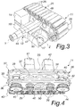
- the two ground movement assemblies 11 and 12 are each constituted by a tracked shoe, one of which, the movement assembly 11, is clearly visible in Figures 3, 4 , 5 , the other movement assembly 12 being understood to be identical and symmetrical.
- the movement assembly 11 comprises a track 25 that is constituted by a chain of flat elements 26 for resting on the ground, which are arranged side by side and are mutually coupled by means of perforated longitudinal brackets 28 and respective transverse pivots 29.
- Each flat element 26 comprises an innermost structural base 30, for example made of a metallic material such as steel and the like, and a resting covering 31, for example made of polymeric material, which is adapted to protect from damage the paving over which it travels.
- One or more friction reduction devices are fitted on the pivots 29, for example roller bearings 32 adapted to receive by resting one or more gliding plates, for example four gliding plates 33, 34, 35 and 36, as in Figures 4 and 5 .
- gliding plates 33, 34, 35 and 36 are thus arranged so that each one slides on a row of roller bearings 32.
- the track 25 is moved by two opposite pinions 37 and 38, which are visible in Figure 4 and each of which is constituted, in the present exemplary embodiment, by two pairs of laterally mutually adjacent sprockets 39 and 40, which are adapted to mesh with the pivots 29.
- the pinions 37 and 38 are actuated by corresponding oil-pressure controlled motors 41 and 42, which are mounted on a gliding plate, for example on the external gliding plate 33.
- the motion is transmitted to the pinions 37 and 38 by means of corresponding transmission devices 43 and 44, for example for example of the type with sprockets 45 and 46, by means of a chain or train of gears or other similar and equivalent devices.
- the transverse rocker 13 which is clearly visible in Figure 3 , comprises a central body 47, from which two opposite hubs 48 and 49 protrude which are intended for insertion in corresponding central coaxial holes 50 of the gliding plates 33, 34, 35 and 36; the two movement assemblies 11 and 12 can therefore oscillate freely independently about the axis Y of the hubs 48 and 49.
- the track 25 is closed so as to surround the gliding plates 33, 34, 35 and 36, and therefore each movement assembly 12 and 13 is rigid and cannot adapt to the underlying ground, compensating with rockers or rollers along the side that rests on the ground; these movement assemblies 12 and 13 are therefore particularly suitable for compact industrial paving, tarmac or concrete roads and less suitable for excessively uneven dirt roads or terrains.
- the rocker 13 acts as an articulation point in order to allow the load to be always equally divided between the two movement assemblies 11 and 12.
- the oil-pressure controlled suspension means 14 and 15 are constituted by two oil-pressure controlled cylinders, indeed 14 and 15, which act as an oil-pressure controlled suspension and as a lifting unit in order to be able to position vertically the movement assemblies 11 and 12 or compensate for the inclinations of the ground in order to be able to perform movements always with the center of gravity at right angles to the ground.
- the oscillating supports 16 and 17 are each constituted by a bracket; the oscillating supports 16 and 17 are coupled to the transverse rocker 13 by means of a longitudinal pivot 50, the axis Z of which is perpendicular to the axis Y of the hubs of the rocker 13 and to the rotation axis X of the rotary distribution unit 19 described hereinafter.
- the load-bearing frame 18 is mounted on the oil-pressure controlled cylinders 14 and 15 and only on them.
- the load-bearing frame 18, in the present exemplary embodiment, which is obviously non-limiting for the invention, has an H-like plan shape which is formed by a central body 54 and by two opposite side walls 55 and 56.
- the central body is provided with a seat 51 for fixing the first part 20 of the rotary distribution unit 19 and there are, between the side walls, two opposite recesses 52 and 53 in which the body of the oil-pressure controlled cylinders 14 and 15 is fixed.
- the oil-pressure controlled circuit adapted to serve the ground movement assemblies 11, 12 and the suspension means 14, 15 is constituted by a series of connected holes provided in the central body 54 and in the side walls 55 and 56 of the load-bearing frame 18; in this manner there are no external tubes for the transfer of the oil to the various user devices.
- Figure 7 shows schematically the oil-pressure controlled circuit of the load-bearing frame 18.
- the following ducts for connection to the rotary distribution unit 19 are provided in the load-bearing duct 18:
- Each pair of motors 41, 42 and 41a and 42a is connected to a corresponding manifold 63 and 64 for the distribution of oil to the connected motors.
- the rotary distribution unit 19 comprises, as mentioned, a first part 20 which is fixed to the load-bearing frame 18 and a second part 21 which can rotate freely about the vertical axis X with respect to the first part 20.
- the first part 20 is constituted by a tubular body, with a flange 65 for fixing to the bottom of the seat 51 of the load-bearing frame 18.
- the second part 19 has a cylindrical central body 66, which is contoured to arrange itself in the central hole of the first part 20, and a connection head 67 which is provided with radial holes for connection to an external oil-pressure controlled service system of the module 10.
- a number of annular ducts 68, 69, 70, 71, 72, 73 that matches the number of ducts formed on the load-bearing frame 18 is formed between the first part 20 and the cylindrical central body 66.
- Each one of the annular ducts 68, 69, 70, 71, 72, 73 is connected and interposed between a corresponding upper duct, which is provided in the second part 21 and is connected to the external oil-pressure controlled service system of the module 10, and a corresponding lower duct, which is provided in the first part 20.
- the upper ducts exit onto the lateral face 74 of the connection head 67, while the lower ducts exit onto the lower face 75 of the first part 20.
- Figure 8 shows schematically in dashes an upper duct 68a and a lower duct 68b for a first annular duct 68, an upper duct 69a and a lower duct 69b for a second annular duct 69, an upper duct 70a and a lower duct 70b for a third annular duct 70, and an upper duct 71a and a lower duct 71b for a fourth annular duct 71.
- connection head 67 is therefore connected to a corresponding user device by means of the rotary distribution unit 19 and the load-bearing frame 18.
- a first radial connection hole 80 is designed for the transit of oil of a first motor 41
- a second radial hole 81 is designed for the transit of oil of a second motor 42
- a third radial hole 82 is designed for the transit of oil of a third motor 41a
- a fourth radial hole 83 is designed for the transit of oil for a fourth motor 42a
- a fifth radial hole 84 is designed for the transit of oil for the lifting of the oil-pressure controlled cylinders 14 and
- a sixth radial hole 85 is designed for the transit of oil for the lowering of the oil-pressure controlled cylinders 14 and 15.
- Annular slots 86 for corresponding sealing rings are formed between two consecutive annular ducts 68, 69, 70, 71, 72, 73 and above the first duct and below the last duct.
- the cylindrical central body 66 of the second part 21 rests on two shoulders of the first part 20 by interposition of friction reduction rings 87 and 88.
- connection head 67 is fixed to the cylindrical central body 66 and rests on the first part 20 by means of a friction reduction ring 89, which is contoured also to prevent the extraction of the cylindrical central body 66 from its seat in the tubular body of the first part 20.
- the center bearing 23 is arranged so as to surround the first part 20 of the rotary distribution unit 19 and is supported by the first part 20, as clearly visible in Figure 8 .
- the center bearing 23 is free to rotate with respect to the first part 20 by interposition of a centering bearing with axial rollers 90 and by resting on a bearing with radial rollers 91, a first lower annular element 92 of which is fixed to the first part 20 while the second upper annular element of which 93 is fixed to the center bearing 23, which rests on it.
- the resting bed 22 is extended transversely so as to cover the movement assemblies 11 and 12 and in an anteroposterior direction so that below there is a technical space for fitting structural reinforcement elements and the relative rotation means 24, as described better hereinafter.
- the resting bed 22 is fixed to the center bearing 23 by means of a central contrast plate 94, clearly visible in the schematic sectional view of Figure 10 , which is provided centrally with a circular opening the edges 95 of which are fixed to the center bearing 23.
- the contrast plate 94 is fixed to the bed 22 by means of stiffening bars 96.
- An interspace 97 is formed between the bed 22 and the contrast plate 94 and is adapted to allow the positioning therein of the connection head 67 of the rotary distribution element 19 and the passage of the pipes for connection to the external oil-pressure controlled service system.
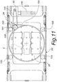
- the means 24 for relative rotation, with respect to said vertical axis X, of said resting bed 22 with respect to said load-bearing frame 18 comprise, in the constructive example described herein, a steering ring 98 with a rotation axis that coincides with the axis X, fixed to the load-bearing frame 18 and extended so as to lie above the movement assemblies 11 and 12.
- the steering ring 98 is turned by means of a gearmotor 99, driven by an electric motor 100, by virtue of the interposition of an intermediate gear 101 that is fitted on a floating tensioning assembly 102.
- the rotation is transmitted from the gearmotor 99 to the intermediate gear 101 by means of a first chain 103.
- the rotation is transmitted from the intermediate gear 101 to the steering ring 98 by means of a second chain 104 arranged so as to pass also in the floating tensioning assembly 102.
- the intermediate gear 101 is obviously constituted by a first upper pinion, which meshes with the first chain 103, and by a second lower pinion, which meshes with the second chain 104.
- the electric gearmotor 99 is provided with a positioning encoder which rotates the assembly to a fixed and determined position.
- These rotation means 24 allow the load-bearing frame 18 with the movement assemblies 11 and 12 to rotate without any constraint, being able to rotate continuously both in one direction and in the opposite direction, therefore through any angle, even greater than 360°.
- the self-propelled module 10 also comprises means for lifting from the ground.
- the means for lifting from the ground are constituted for example by four lifting cylinders 105 arranged at the corners of the frame in which the steering ring 98 is inscribed; said cylinders are intended for two purposes:
- a self-propelled module 10 according to the invention is designed to be connected structurally and hydraulically to at least two other identical self-propelled modules in order to provide a modular system for oversize loads.
- FIG. 1 An example of a modular system for oversize loads composed of self-propelled modules according to the invention is exemplified in Figure 1 and is generally designated therein by the reference numeral 110.
- the modular system 110 comprises four self-propelled modules 10, 10a, 10b, 10c, which are coupled structurally by means of longitudinal members 111 and cross-members 112.
- the system is preferably composed of three or four assemblies on which the load rests.
- a single self-propelled module as a traction system to be applied for example to a carriage with wheels.
- the three or four modules are mutually connected in order to provide a perpendicular and parallel arrangement thereof and to keep them upright.
- the system does not operate like a truck, which has a bed on which the load rests, but behaves like the trucks of a railcar, in which the railcar itself is rigid (it acts as the load) and the trucks with iron wheels that discharge the weight onto the rail are the two resting elements (self-propelled modules 10).
- the described system 110 is based on mutually connected modules, but it is to be understood that a modular system with self-propelled modules according to the invention can work also without rigid connections when multiple modules are fixed safely and stably to a same object to be transported.
- Each self-propelled module 10, 10a, 10b, 10c is connected by means of the hydraulic tubes and cables to a wheeled control unit 115, which is managed by means of an industrial PC 116, which is organized to control the module steering and lifting and lowering variables.
- the external service hydraulic system is to be understood as being contained within the wheeled control unit 115.
- the electrical system for supplying power to the gearmotor 99 and for the operation of the wheeled control unit 115 is supported by the wheeled control unit 115 itself.
- the wheeled control unit 115 is structurally connected to at least one self-propelled module 10c by means of an articulated towing arm 117.
- the articulated towing arm 117 also bears the cables and tubes for connection to the self-propelled modules.
- the electric motor 100 that manages steering is capable of varying the rotation rate, thus allowing a rotation at different angles but in the same times, which is fundamental for achieving the steering geometry of four self-propelled modules arranged in four different points.
- a modular system for oversize loads composed of self-propelled modules according to the invention is formed:
- a modular system with self-propelled modules according to the invention can be expanded at will to multiples of two modules, which in turn will be connected to others so as to always obtain three suspension points.
- a group of hydraulically interconnected modules defines a single suspension point; it is therefore possible to have three groups of "n" modules which form a modular transport system always with three suspension points.
- Steering management is electric at low voltage and is controlled by a motor that is managed by a drive with feedback which, by means of the encoder of the electric motor 100 of the gearmotor 99, knows exactly the spatial position of the axis of the self-propelled modules 10.
- the industrial computer 116 connected to the system manages the information that arrives from a radio control of the modular system 110.
- An operator uses the radio control to steer the self-propelled modules. Steering can be for example of five types and more precisely:
- An adapted user interface allows to choose a preset configuration from a set of "n" possibilities depending on the desired number of modules.
- the invention has provided a compact self-propelled module the resting surface of which is low, i.e., close to the ground, and at the same time capable of supporting and moving tens of tons of load; a self-propelled module 10 according to the invention in fact can be provided with such dimensions that the bed 22 is spaced from the ground by approximately 40 centimeters and the steering ring has a diameter of 1 meter; such a self-propelled module is capable of supporting approximately 40 tons.
- the invention provides a self-propelled module that is capable of better distributing the weight that is supported on the ground with respect to vehicles of the known type, by virtue of the movement assemblies constituted by tracked shoes as described above.
- the invention has provided a self-propelled module that is capable of a better steering angle than modular systems and vehicles of the known type.
- the invention has provided a self-propelled module that can be composed with other identical modules so as to form a modular transportation system that can be adapted to the most disparate requirements of transportation, both in terms of weights and in terms of dimensions of the bodies to be transported.
Landscapes
- Engineering & Computer Science (AREA)
- Mechanical Engineering (AREA)
- Transportation (AREA)
- Life Sciences & Earth Sciences (AREA)
- Forests & Forestry (AREA)
- Health & Medical Sciences (AREA)
- Public Health (AREA)
- Forklifts And Lifting Vehicles (AREA)
- Invalid Beds And Related Equipment (AREA)
- Portable Nailing Machines And Staplers (AREA)
- Control Of Motors That Do Not Use Commutators (AREA)
Claims (16)
- Selbstangetriebenes Modul (10) für übergroße Lasten, das aufweist:- zwei Bodenbewegungsanordnungen (11, 12) mit öldruckgesteuerter Betätigung,- eine Querschwinge (13), die zwischen den beiden Bewegungsanordnungen (11, 12), die unabhängig daran gekoppelt sind, angeordnet ist,dadurch gekennzeichnet, dass das Modul aufweist:- öldruckgesteuerte Aufhängungsmittel (14, 15), die an entsprechenden oszillierenden Stützen (16, 17) angeordnet sind, die mit der Querschwinge (13) verbunden sind,- einen lasttragenden Rahmen (18), der von den öldruckgesteuerten Aufhängungsmitteln (14, 15) gestützt wird und einen öldruckgesteuerten Kreislauf aufweist, der dazu ausgelegt ist, die Bodenbewegungsanordnungen (11, 12) und die Aufhängungsmittel (14, 15) zu versorgen,- eine drehende Verteilungseinheit (19), die eine vertikale Achse (X) hat und an dem lasttragenden Rahmen (18) angebracht ist, um die Bodenbewegungsanordnungen (11, 12) und die öldruckgesteuerten Aufhängungsmittel (14, 15) zu versorgen, wobei ein erster Teil (20) der drehenden Verteilungseinheit (19) an dem lasttragenden Rahmen (18) befestigt ist und ein zweiter Teil (21) sich bezüglich des ersten Teils (20) frei um die vertikale Achse (X) drehen kann,- ein Auflagebett (22), das von einem Mittellager (23) gestützt wird, das koaxial zu der drehenden Verteilungseinheit (19) ist,- wobei sich unter dem Auflagebett (22) Mittel zur relativen Drehung des Auflagebetts (22) bezüglich des lasttragenden Rahmens (18) um die vertikale Achse (X) befinden.
- Selbstangetriebenes Modul nach Anspruch 1, dadurch gekennzeichnet, dass die Bodenbewegungsanordnungen (11, 12) jeweils aus einem Kettenaufspannkörper bestehen, der einen Strang (25) aufweist, der aus einer Kette flacher Elemente (26) zur Auflage auf dem Boden besteht, die nebeneinander angeordnet und mittels perforierter länglicher Halterungen (28) und jeweiliger Querzapfen (29) miteinander verbunden sind.
- Selbstangetriebenes Modul nach Anspruch 2, dadurch gekennzeichnet, dass ein oder mehrere Reibungsreduzierungsvorrichtungen, zum Beispiel Rollenlager (32), an den Zapfen (29) angebracht und dazu ausgelegt sind, eine oder mehrere Gleitplatten (33, 34, 35, 36) durch Auflagekontakt aufzunehmen, die so angeordnet sind, dass jede auf einer Reihe von Rollenlagern (32) gleitet.
- Selbstangetriebenes Modul nach einem oder mehreren der vorhergehenden Ansprüche, dadurch gekennzeichnet, dass der Strang (25) von zwei gegenüberliegenden Antriebsrädern (37, 38) bewegt wird, die wiederum durch entsprechende öldruckgesteuerte Motoren (41, 42), welche auf einer Gleitplatte (33) angebracht sind, betätigt werden.
- Selbstangetriebenes Modul nach einem oder mehreren der vorhergehenden Ansprüche, dadurch gekennzeichnet, dass die Querschwinge (13) einen mittigen Körper (47) aufweist, von dem sich zwei gegenüberliegende Naben (48, 49) erstrecken, die dazu vorgesehen sind, in korrespondierende mittige koaxiale Löcher (50) der Gleitplatten (33, 34, 35, 36) eingeführt zu werden.
- Selbstangetriebenes Modul nach einem oder mehreren der vorhergehenden Ansprüche, dadurch gekennzeichnet, dass die öldruckgesteuerten Aufhängungsmittel (14, 15) aus zwei öldruckgesteuerten Zylindern (14, 15) bestehen.
- Selbstangetriebenes Modul nach einem oder mehreren der vorhergehenden Ansprüche, dadurch gekennzeichnet, dass der lasttragende Rahmen (18) eine H-artige plane Form hat, die aus einem mittigen Körper (54) und aus zwei gegenüberliegenden Seitenwänden (55, 56) gebildet wird, wobei der mittige Körper einen Sitz (51) zum Befestigen des ersten Teils (20) der drehenden Verteilungseinheit (19) hat, wobei zwei gegenüberliegende Ausnehmungen (52, 53) zwischen den Seitenwänden ausgebildet sind, in denen der Körper der öldruckgesteuerten Zylinder (14, 15) befestigt ist.
- Selbstangetriebenes Modul nach einem oder mehreren der vorhergehenden Ansprüche, dadurch gekennzeichnet, dass ein öldruckgesteuerter Kreislauf, der dazu ausgelegt ist, die Bodenbewegungsanordnungen (11, 12) und die Aufhängungsmittel (14, 15) zu versorgen, aus einer Reihe verbundener Löcher besteht, die in dem mittigen Körper (54) und in den Seitenwänden (55, 56) des lasttragenden Rahmens (18) vorgesehen sind.
- Selbstangetriebenes Modul nach einem oder mehreren der vorhergehenden Ansprüche, dadurch gekennzeichnet, dass die folgenden Leitungen zur Verbindung mit der drehenden Verteilungseinheit (19) in dem lasttragenden Rahmen (18) vorgesehen sind:- abgehende und rückführende Leitungen (57, 58) für das Öl in Richtung der öldruckgesteuerten Zylinder (14, 15),- eine Leitung (59) zur Verbindung mit einem ersten Motor (41) der ersten Bewegungsanordnung (11),- eine Leitung (60) zur Verbindung mit einem zweiten Motor (42) der ersten Bewegungsanordnung (11),- eine Leitung (61) zur Verbindung mit einem ersten Motor (41a) der zweiten Bewegungsanordnung (12),- eine Leitung (62) zur Verbindung mit einem zweiten Motor (42a) der zweiten Bewegungsanordnung (12).
- Selbstangetriebenes Modul nach einem oder mehreren der vorhergehenden Ansprüche, dadurch gekennzeichnet, dass der erste Teil (20) aus einem rohrförmigen Körper besteht, mit einem Flansch (65) zum Befestigen am Boden des Sitzes (51) des lasttragenden Rahmens (18).
- Selbstangetriebenes Modul nach einem oder mehreren der vorhergehenden Ansprüche, dadurch gekennzeichnet, dass der zweite Teil (19) einen zylindrischen mittigen Körper (66) hat, der dazu konturiert ist, sich in dem mittigen Loch des ersten Teils (20) anzuordnen, und einen Verbindungskopf (67), der mit radialen Löchern zur Verbindung mit einem externen Versorgungshydrauliksystem des Moduls (10) versehen ist.
- Selbstangetriebenes Modul nach einem oder mehreren der vorhergehenden Ansprüche, dadurch gekennzeichnet, dass zwischen dem ersten Teil (20) und dem zylindrischen mittigen Körper (66) so viele ringförmige Leitungen (68, 69, 70, 71, 72, 73) vorhanden sind wie Leitungen an dem lasttragenden Rahmen (18) ausgebildet sind, wobei jede der ringförmigen Leitungen (68, 69, 70, 71, 72, 73) geschaltet und eingefügt ist zwischen- eine korrespondierende obere Leitung, die in dem zweiten Teil (21) vorgesehen ist und mit dem externen Vesorgungshydrauliksystem des Moduls (10) verbunden ist,- und eine korrespondierende untere Leitung, die in dem ersten Teil (20) vorgesehen ist.
- Selbstangetriebenes Modul nach einem oder mehreren der vorhergehenden Ansprüche, dadurch gekennzeichnet, dass das Mittellager (23) so angeordnet ist, dass es den ersten Teil (20) der drehenden Verteilungseinheit (19) umgibt und von dem ersten Teil (20) gestützt wird, wobei sich das Mittellager (23) bezüglich des ersten Teils (20) aufgrund der Zwischenschaltung eines Zentrierlagers mit axialen Rollen (90) frei drehen kann, und auf einem Lager mit radialen Rollen (91) aufliegt, von denen ein erstes unteres ringförmiges Element (92) an dem ersten Teil (20) befestigt ist, während das zweite obere ringförmige Element (93) an dem Mittellager (23) befestigt ist, das darauf aufliegt.
- Selbstangetriebenes Modul nach einem oder mehreren der vorhergehenden Ansprüche, dadurch gekennzeichnet, dass das Auflagebett (22) an dem Mittellager (23) mittels einer mittigen Kontrastplatte (94) befestigt ist, die mittig mit einer kreisförmigen Öffnung versehen ist, deren Kanten (95) an dem Mittellager (23) befestigt sind.
- Selbstangetriebenes Modul nach einem oder mehreren der vorhergehenden Ansprüche, dadurch gekennzeichnet, dass sich zwischen dem Bett (22) und der Kontrastplatte (94) ein Zwischenraum (97) befindet, der dazu ausgelegt ist, das Platzieren des Verbindungskopfs (67) der drehenden Verteilungseinheit (19) darin und das Durchtreten der Rohre zur Verbindung mit dem externen Hydraulikversorgungssystem zu ermöglichen.
- Selbstangetriebenes Modul nach einem oder mehreren der vorhergehenden Ansprüche, dadurch gekennzeichnet, dass die Mittel (24) zur relativen Drehung bezüglich der vertikalen Achse (X) des Auflagebetts (22) bezüglich des lasttragenden Rahmens (18) einen Lenkring (98) mit einer Drehachse aufweisen, die mit der Achse (X) zusammenfällt, befestigt an dem lasttragenden Rahmen (18) und erweitert, um über den Bewegungseinheiten (11, 12) zu liegen, wobei der Lenkring (98) mittels eines Getriebemotors (99) gedreht wird, der von einem Elektromotor (100) betätigt wird, durch Zwischenschaltung eines Zwischengetriebes (101), das an einer schwimmenden Anordnung (102) angebracht ist, zum Spannen, wobei die Drehung von dem Getriebemotor (99) mittels einer ersten Kette (103) an das Zwischengetriebe (101) übertragen wird, wobei die Drehung von dem Zwischengetriebe (101) mittels einer zweiten Kette (104), die dazu ausgelegt ist, auch in die schwimmende Spannungsanordnung (102) durchzugehen, an den Lenkring (98) übertragen wird.
Priority Applications (3)
| Application Number | Priority Date | Filing Date | Title |
|---|---|---|---|
| PL17728792T PL3463976T3 (pl) | 2016-05-31 | 2017-05-30 | Moduł samobieżny do pojazdów nienormatywnych |
| HRP20201236TT HRP20201236T1 (hr) | 2016-05-31 | 2017-05-30 | Samohodni modul za terete velikih dimenzija |
| SI201730367T SI3463976T1 (sl) | 2016-05-31 | 2017-05-30 | Modul z lastnim pogonom za prevelike tovore |
Applications Claiming Priority (2)
| Application Number | Priority Date | Filing Date | Title |
|---|---|---|---|
| ITUB20163959 | 2016-05-31 | ||
| PCT/EP2017/063052 WO2017207578A1 (en) | 2016-05-31 | 2017-05-30 | Self-propelled module for oversize loads |
Publications (2)
| Publication Number | Publication Date |
|---|---|
| EP3463976A1 EP3463976A1 (de) | 2019-04-10 |
| EP3463976B1 true EP3463976B1 (de) | 2020-05-13 |
Family
ID=65562966
Family Applications (1)
| Application Number | Title | Priority Date | Filing Date |
|---|---|---|---|
| EP17728792.7A Active EP3463976B1 (de) | 2016-05-31 | 2017-05-30 | Selbstangetriebenes modul für übergrosse lasten |
Country Status (7)
| Country | Link |
|---|---|
| EP (1) | EP3463976B1 (de) |
| DK (1) | DK3463976T3 (de) |
| ES (1) | ES2810353T3 (de) |
| HR (1) | HRP20201236T1 (de) |
| HU (1) | HUE050039T2 (de) |
| PL (1) | PL3463976T3 (de) |
| SI (1) | SI3463976T1 (de) |
-
2017
- 2017-05-30 PL PL17728792T patent/PL3463976T3/pl unknown
- 2017-05-30 HR HRP20201236TT patent/HRP20201236T1/hr unknown
- 2017-05-30 HU HUE17728792A patent/HUE050039T2/hu unknown
- 2017-05-30 DK DK17728792.7T patent/DK3463976T3/da active
- 2017-05-30 SI SI201730367T patent/SI3463976T1/sl unknown
- 2017-05-30 ES ES17728792T patent/ES2810353T3/es active Active
- 2017-05-30 EP EP17728792.7A patent/EP3463976B1/de active Active
Non-Patent Citations (1)
| Title |
|---|
| None * |
Also Published As
| Publication number | Publication date |
|---|---|
| HUE050039T2 (hu) | 2020-11-30 |
| DK3463976T3 (da) | 2020-08-10 |
| HRP20201236T1 (hr) | 2020-11-13 |
| SI3463976T1 (sl) | 2020-11-30 |
| EP3463976A1 (de) | 2019-04-10 |
| ES2810353T3 (es) | 2021-03-08 |
| PL3463976T3 (pl) | 2020-11-16 |
Similar Documents
| Publication | Publication Date | Title |
|---|---|---|
| AU2017272612B2 (en) | Self-propelled module for oversize loads | |
| US4599030A (en) | Marginal terrain straddle-lift container handler | |
| US7950478B2 (en) | Heavy capacity transporter having multiple track-axles | |
| US20110094815A1 (en) | Stack axle assembly and transporters having the same | |
| GB2260127A (en) | Computer controlled conveying and storage system | |
| JP2009012089A (ja) | 昇降及び回転機能付き搬送台車並びにそれを用いた自動車組立ライン | |
| DE102012102648A1 (de) | Modulares Bodentransportsystem, insbesondere selbstfahrend und für schwere Montage- und Logistikprozesse | |
| JP7248218B2 (ja) | 無人搬送車または自律移動ロボット等の自律走行車 | |
| CN103303637A (zh) | 机动链辊 | |
| CA2235847C (en) | Vehicle for handling various materials or operating units in sheds, airports, markets and the like | |
| CA3025719C (en) | Self-propelled module for oversize loads | |
| US5335780A (en) | Multi-direction package movement device | |
| CN107839896A (zh) | 一种机场物资装卸平台底盘 | |
| EP3848324B1 (de) | Fahrerloses transportfahrzeug | |
| EP3463976A1 (de) | Selbstangetriebenes modul für übergrosse lasten | |
| US11597435B2 (en) | Drilling rig | |
| US8813890B2 (en) | Tricycle lifting suspension transporter | |
| US20140048343A1 (en) | Multi-axis articulating crawler | |
| EP2774812B1 (de) | Verfahren zur Herstellung eines Betonelements | |
| EP2692581B1 (de) | Fahrzeug für den Transport von Baggerfahrzeugen | |
| CN116750427B (zh) | 运输设备及其使用方法以及移动小车 | |
| JP2026043652A (ja) | 球形ガスホルダー又は球形タンクの搬送方法及びこれに用いる搬送設備 | |
| KR102348001B1 (ko) | 주행형 pc 거더 운반용 대차 | |
| US20160332846A1 (en) | Uniform footprint multi-wheel end truck for a crane | |
| JP2025094612A (ja) | 管運搬車 |
Legal Events
| Date | Code | Title | Description |
|---|---|---|---|
| STAA | Information on the status of an ep patent application or granted ep patent |
Free format text: STATUS: UNKNOWN |
|
| STAA | Information on the status of an ep patent application or granted ep patent |
Free format text: STATUS: THE INTERNATIONAL PUBLICATION HAS BEEN MADE |
|
| PUAI | Public reference made under article 153(3) epc to a published international application that has entered the european phase |
Free format text: ORIGINAL CODE: 0009012 |
|
| STAA | Information on the status of an ep patent application or granted ep patent |
Free format text: STATUS: REQUEST FOR EXAMINATION WAS MADE |
|
| 17P | Request for examination filed |
Effective date: 20181220 |
|
| AK | Designated contracting states |
Kind code of ref document: A1 Designated state(s): AL AT BE BG CH CY CZ DE DK EE ES FI FR GB GR HR HU IE IS IT LI LT LU LV MC MK MT NL NO PL PT RO RS SE SI SK SM TR |
|
| AX | Request for extension of the european patent |
Extension state: BA ME |
|
| DAV | Request for validation of the european patent (deleted) | ||
| DAX | Request for extension of the european patent (deleted) | ||
| GRAP | Despatch of communication of intention to grant a patent |
Free format text: ORIGINAL CODE: EPIDOSNIGR1 |
|
| STAA | Information on the status of an ep patent application or granted ep patent |
Free format text: STATUS: GRANT OF PATENT IS INTENDED |
|
| INTG | Intention to grant announced |
Effective date: 20191030 |
|
| GRAS | Grant fee paid |
Free format text: ORIGINAL CODE: EPIDOSNIGR3 |
|
| GRAA | (expected) grant |
Free format text: ORIGINAL CODE: 0009210 |
|
| STAA | Information on the status of an ep patent application or granted ep patent |
Free format text: STATUS: THE PATENT HAS BEEN GRANTED |
|
| AK | Designated contracting states |
Kind code of ref document: B1 Designated state(s): AL AT BE BG CH CY CZ DE DK EE ES FI FR GB GR HR HU IE IS IT LI LT LU LV MC MK MT NL NO PL PT RO RS SE SI SK SM TR |
|
| REG | Reference to a national code |
Ref country code: GB Ref legal event code: FG4D |
|
| REG | Reference to a national code |
Ref country code: CH Ref legal event code: EP |
|
| REG | Reference to a national code |
Ref country code: DE Ref legal event code: R096 Ref document number: 602017016551 Country of ref document: DE |
|
| REG | Reference to a national code |
Ref country code: AT Ref legal event code: REF Ref document number: 1269835 Country of ref document: AT Kind code of ref document: T Effective date: 20200615 |
|
| REG | Reference to a national code |
Ref country code: FI Ref legal event code: FGE |
|
| REG | Reference to a national code |
Ref country code: HR Ref legal event code: TUEP Ref document number: P20201236T Country of ref document: HR |
|
| REG | Reference to a national code |
Ref country code: DK Ref legal event code: T3 Effective date: 20200806 |
|
| REG | Reference to a national code |
Ref country code: CH Ref legal event code: NV Representative=s name: MODIANO AND PARTNERS S.A., CH |
|
| REG | Reference to a national code |
Ref country code: NL Ref legal event code: FP |
|
| REG | Reference to a national code |
Ref country code: SE Ref legal event code: TRGR |
|
| REG | Reference to a national code |
Ref country code: NO Ref legal event code: T2 Effective date: 20200513 |
|
| REG | Reference to a national code |
Ref country code: LT Ref legal event code: MG4D |
|
| PG25 | Lapsed in a contracting state [announced via postgrant information from national office to epo] |
Ref country code: PT Free format text: LAPSE BECAUSE OF FAILURE TO SUBMIT A TRANSLATION OF THE DESCRIPTION OR TO PAY THE FEE WITHIN THE PRESCRIBED TIME-LIMIT Effective date: 20200914 Ref country code: IS Free format text: LAPSE BECAUSE OF FAILURE TO SUBMIT A TRANSLATION OF THE DESCRIPTION OR TO PAY THE FEE WITHIN THE PRESCRIBED TIME-LIMIT Effective date: 20200913 Ref country code: GR Free format text: LAPSE BECAUSE OF FAILURE TO SUBMIT A TRANSLATION OF THE DESCRIPTION OR TO PAY THE FEE WITHIN THE PRESCRIBED TIME-LIMIT Effective date: 20200814 Ref country code: LT Free format text: LAPSE BECAUSE OF FAILURE TO SUBMIT A TRANSLATION OF THE DESCRIPTION OR TO PAY THE FEE WITHIN THE PRESCRIBED TIME-LIMIT Effective date: 20200513 |
|
| REG | Reference to a national code |
Ref country code: SK Ref legal event code: T3 Ref document number: E 35018 Country of ref document: SK |
|
| REG | Reference to a national code |
Ref country code: HR Ref legal event code: ODRP Ref document number: P20201236 Country of ref document: HR Payment date: 20201103 Year of fee payment: 4 Ref country code: HR Ref legal event code: T1PR Ref document number: P20201236 Country of ref document: HR |
|
| PG25 | Lapsed in a contracting state [announced via postgrant information from national office to epo] |
Ref country code: LV Free format text: LAPSE BECAUSE OF FAILURE TO SUBMIT A TRANSLATION OF THE DESCRIPTION OR TO PAY THE FEE WITHIN THE PRESCRIBED TIME-LIMIT Effective date: 20200513 Ref country code: RS Free format text: LAPSE BECAUSE OF FAILURE TO SUBMIT A TRANSLATION OF THE DESCRIPTION OR TO PAY THE FEE WITHIN THE PRESCRIBED TIME-LIMIT Effective date: 20200513 |
|
| REG | Reference to a national code |
Ref country code: HU Ref legal event code: AG4A Ref document number: E050039 Country of ref document: HU |
|
| PG25 | Lapsed in a contracting state [announced via postgrant information from national office to epo] |
Ref country code: AL Free format text: LAPSE BECAUSE OF FAILURE TO SUBMIT A TRANSLATION OF THE DESCRIPTION OR TO PAY THE FEE WITHIN THE PRESCRIBED TIME-LIMIT Effective date: 20200513 |
|
| PG25 | Lapsed in a contracting state [announced via postgrant information from national office to epo] |
Ref country code: EE Free format text: LAPSE BECAUSE OF FAILURE TO SUBMIT A TRANSLATION OF THE DESCRIPTION OR TO PAY THE FEE WITHIN THE PRESCRIBED TIME-LIMIT Effective date: 20200513 Ref country code: IT Free format text: LAPSE BECAUSE OF FAILURE TO SUBMIT A TRANSLATION OF THE DESCRIPTION OR TO PAY THE FEE WITHIN THE PRESCRIBED TIME-LIMIT Effective date: 20200513 Ref country code: SM Free format text: LAPSE BECAUSE OF FAILURE TO SUBMIT A TRANSLATION OF THE DESCRIPTION OR TO PAY THE FEE WITHIN THE PRESCRIBED TIME-LIMIT Effective date: 20200513 |
|
| REG | Reference to a national code |
Ref country code: AT Ref legal event code: UEP Ref document number: 1269835 Country of ref document: AT Kind code of ref document: T Effective date: 20200513 |
|
| REG | Reference to a national code |
Ref country code: DE Ref legal event code: R097 Ref document number: 602017016551 Country of ref document: DE |
|
| PG25 | Lapsed in a contracting state [announced via postgrant information from national office to epo] |
Ref country code: MC Free format text: LAPSE BECAUSE OF FAILURE TO SUBMIT A TRANSLATION OF THE DESCRIPTION OR TO PAY THE FEE WITHIN THE PRESCRIBED TIME-LIMIT Effective date: 20200513 |
|
| REG | Reference to a national code |
Ref country code: ES Ref legal event code: FG2A Ref document number: 2810353 Country of ref document: ES Kind code of ref document: T3 Effective date: 20210308 |
|
| PLBE | No opposition filed within time limit |
Free format text: ORIGINAL CODE: 0009261 |
|
| STAA | Information on the status of an ep patent application or granted ep patent |
Free format text: STATUS: NO OPPOSITION FILED WITHIN TIME LIMIT |
|
| PG25 | Lapsed in a contracting state [announced via postgrant information from national office to epo] |
Ref country code: LU Free format text: LAPSE BECAUSE OF NON-PAYMENT OF DUE FEES Effective date: 20200530 |
|
| 26N | No opposition filed |
Effective date: 20210216 |
|
| REG | Reference to a national code |
Ref country code: HR Ref legal event code: ODRP Ref document number: P20201236 Country of ref document: HR Payment date: 20210426 Year of fee payment: 5 |
|
| PG25 | Lapsed in a contracting state [announced via postgrant information from national office to epo] |
Ref country code: MT Free format text: LAPSE BECAUSE OF FAILURE TO SUBMIT A TRANSLATION OF THE DESCRIPTION OR TO PAY THE FEE WITHIN THE PRESCRIBED TIME-LIMIT Effective date: 20200513 Ref country code: CY Free format text: LAPSE BECAUSE OF FAILURE TO SUBMIT A TRANSLATION OF THE DESCRIPTION OR TO PAY THE FEE WITHIN THE PRESCRIBED TIME-LIMIT Effective date: 20200513 |
|
| REG | Reference to a national code |
Ref country code: HR Ref legal event code: ODRP Ref document number: P20201236 Country of ref document: HR Payment date: 20220421 Year of fee payment: 6 |
|
| PG25 | Lapsed in a contracting state [announced via postgrant information from national office to epo] |
Ref country code: MK Free format text: LAPSE BECAUSE OF FAILURE TO SUBMIT A TRANSLATION OF THE DESCRIPTION OR TO PAY THE FEE WITHIN THE PRESCRIBED TIME-LIMIT Effective date: 20200513 |
|
| REG | Reference to a national code |
Ref country code: HR Ref legal event code: ODRP Ref document number: P20201236 Country of ref document: HR Payment date: 20230427 Year of fee payment: 7 |
|
| REG | Reference to a national code |
Ref country code: HR Ref legal event code: ODRP Ref document number: P20201236 Country of ref document: HR Payment date: 20240423 Year of fee payment: 8 |
|
| PGFP | Annual fee paid to national office [announced via postgrant information from national office to epo] |
Ref country code: SE Payment date: 20250311 Year of fee payment: 9 |
|
| REG | Reference to a national code |
Ref country code: HR Ref legal event code: ODRP Ref document number: P20201236 Country of ref document: HR Payment date: 20250424 Year of fee payment: 9 |
|
| PGFP | Annual fee paid to national office [announced via postgrant information from national office to epo] |
Ref country code: NL Payment date: 20250523 Year of fee payment: 9 |
|
| PGFP | Annual fee paid to national office [announced via postgrant information from national office to epo] |
Ref country code: FI Payment date: 20250523 Year of fee payment: 9 |
|
| PGFP | Annual fee paid to national office [announced via postgrant information from national office to epo] |
Ref country code: PL Payment date: 20250428 Year of fee payment: 9 Ref country code: DE Payment date: 20250602 Year of fee payment: 9 |
|
| PGFP | Annual fee paid to national office [announced via postgrant information from national office to epo] |
Ref country code: ES Payment date: 20250602 Year of fee payment: 9 Ref country code: GB Payment date: 20250524 Year of fee payment: 9 Ref country code: DK Payment date: 20250520 Year of fee payment: 9 |
|
| PGFP | Annual fee paid to national office [announced via postgrant information from national office to epo] |
Ref country code: HU Payment date: 20250430 Year of fee payment: 9 Ref country code: NO Payment date: 20250527 Year of fee payment: 9 |
|
| PGFP | Annual fee paid to national office [announced via postgrant information from national office to epo] |
Ref country code: BE Payment date: 20250520 Year of fee payment: 9 |
|
| PGFP | Annual fee paid to national office [announced via postgrant information from national office to epo] |
Ref country code: HR Payment date: 20250424 Year of fee payment: 9 |
|
| PGFP | Annual fee paid to national office [announced via postgrant information from national office to epo] |
Ref country code: FR Payment date: 20250520 Year of fee payment: 9 |
|
| PGFP | Annual fee paid to national office [announced via postgrant information from national office to epo] |
Ref country code: BG Payment date: 20250529 Year of fee payment: 9 |
|
| PGFP | Annual fee paid to national office [announced via postgrant information from national office to epo] |
Ref country code: CH Payment date: 20250601 Year of fee payment: 9 |
|
| PGFP | Annual fee paid to national office [announced via postgrant information from national office to epo] |
Ref country code: AT Payment date: 20250526 Year of fee payment: 9 Ref country code: RO Payment date: 20250506 Year of fee payment: 9 |
|
| PGFP | Annual fee paid to national office [announced via postgrant information from national office to epo] |
Ref country code: TR Payment date: 20250521 Year of fee payment: 9 Ref country code: SK Payment date: 20250425 Year of fee payment: 9 |
|
| PGFP | Annual fee paid to national office [announced via postgrant information from national office to epo] |
Ref country code: CZ Payment date: 20250428 Year of fee payment: 9 |
|
| PGFP | Annual fee paid to national office [announced via postgrant information from national office to epo] |
Ref country code: IE Payment date: 20250521 Year of fee payment: 9 |
|
| PGFP | Annual fee paid to national office [announced via postgrant information from national office to epo] |
Ref country code: SI Payment date: 20250429 Year of fee payment: 9 |