EP3463952B1 - Dichtung für eine versenkbare fensterscheibe eines fahrzeugtürfensters - Google Patents
Dichtung für eine versenkbare fensterscheibe eines fahrzeugtürfensters Download PDFInfo
- Publication number
- EP3463952B1 EP3463952B1 EP17717078.4A EP17717078A EP3463952B1 EP 3463952 B1 EP3463952 B1 EP 3463952B1 EP 17717078 A EP17717078 A EP 17717078A EP 3463952 B1 EP3463952 B1 EP 3463952B1
- Authority
- EP
- European Patent Office
- Prior art keywords
- seal
- leg
- profile
- frame part
- seal according
- Prior art date
- Legal status (The legal status is an assumption and is not a legal conclusion. Google has not performed a legal analysis and makes no representation as to the accuracy of the status listed.)
- Active
Links
Images

Classifications
-
- B—PERFORMING OPERATIONS; TRANSPORTING
- B60—VEHICLES IN GENERAL
- B60J—WINDOWS, WINDSCREENS, NON-FIXED ROOFS, DOORS, OR SIMILAR DEVICES FOR VEHICLES; REMOVABLE EXTERNAL PROTECTIVE COVERINGS SPECIALLY ADAPTED FOR VEHICLES
- B60J10/00—Sealing arrangements
- B60J10/70—Sealing arrangements specially adapted for windows or windscreens
- B60J10/74—Sealing arrangements specially adapted for windows or windscreens for sliding window panes, e.g. sash guides
- B60J10/76—Sealing arrangements specially adapted for windows or windscreens for sliding window panes, e.g. sash guides for window sashes; for glass run channels
-
- B—PERFORMING OPERATIONS; TRANSPORTING
- B60—VEHICLES IN GENERAL
- B60J—WINDOWS, WINDSCREENS, NON-FIXED ROOFS, DOORS, OR SIMILAR DEVICES FOR VEHICLES; REMOVABLE EXTERNAL PROTECTIVE COVERINGS SPECIALLY ADAPTED FOR VEHICLES
- B60J10/00—Sealing arrangements
- B60J10/15—Sealing arrangements characterised by the material
-
- B—PERFORMING OPERATIONS; TRANSPORTING
- B60—VEHICLES IN GENERAL
- B60J—WINDOWS, WINDSCREENS, NON-FIXED ROOFS, DOORS, OR SIMILAR DEVICES FOR VEHICLES; REMOVABLE EXTERNAL PROTECTIVE COVERINGS SPECIALLY ADAPTED FOR VEHICLES
- B60J10/00—Sealing arrangements
- B60J10/15—Sealing arrangements characterised by the material
- B60J10/16—Sealing arrangements characterised by the material consisting of two or more plastic materials having different physical or chemical properties
-
- B—PERFORMING OPERATIONS; TRANSPORTING
- B60—VEHICLES IN GENERAL
- B60J—WINDOWS, WINDSCREENS, NON-FIXED ROOFS, DOORS, OR SIMILAR DEVICES FOR VEHICLES; REMOVABLE EXTERNAL PROTECTIVE COVERINGS SPECIALLY ADAPTED FOR VEHICLES
- B60J10/00—Sealing arrangements
- B60J10/20—Sealing arrangements characterised by the shape
- B60J10/24—Sealing arrangements characterised by the shape having tubular parts
-
- B—PERFORMING OPERATIONS; TRANSPORTING
- B60—VEHICLES IN GENERAL
- B60J—WINDOWS, WINDSCREENS, NON-FIXED ROOFS, DOORS, OR SIMILAR DEVICES FOR VEHICLES; REMOVABLE EXTERNAL PROTECTIVE COVERINGS SPECIALLY ADAPTED FOR VEHICLES
- B60J10/00—Sealing arrangements
- B60J10/20—Sealing arrangements characterised by the shape
- B60J10/24—Sealing arrangements characterised by the shape having tubular parts
- B60J10/246—Sealing arrangements characterised by the shape having tubular parts having projections, e.g. ribs, within the tubular parts
-
- B—PERFORMING OPERATIONS; TRANSPORTING
- B60—VEHICLES IN GENERAL
- B60J—WINDOWS, WINDSCREENS, NON-FIXED ROOFS, DOORS, OR SIMILAR DEVICES FOR VEHICLES; REMOVABLE EXTERNAL PROTECTIVE COVERINGS SPECIALLY ADAPTED FOR VEHICLES
- B60J10/00—Sealing arrangements
- B60J10/30—Sealing arrangements characterised by the fastening means
- B60J10/32—Sealing arrangements characterised by the fastening means using integral U-shaped retainers
Definitions
- the invention relates to a seal between a frame part of a vehicle door window and the upper edge of a retractable pane of the vehicle door window.
- Known seals of this type comprise a sealing profile 7' made of EPDM or TPE material with a Fig. 4
- the sealing profile 7' is placed on a flange 9', which is supported by an upper, Fig. 4
- the frame part 5' shown in cross-section protrudes perpendicularly to the plane of a retractable window pane 3'.
- the sealing profile 7' further has sealing lips 20', by means of which the upper frame part 5' can be sealed against an edge surface 21' of a door opening in a vehicle body 6'.
- the present invention provides a new seal of the type mentioned at the outset with a sealing profile which, with a simplified construction of the upper frame part of the vehicle door window receiving the sealing profile, can be securely mounted on the upper frame part with less effort than conventional EPDM or TPE sealing profiles and which, moreover, brings about significant savings in material costs and weight.
- the sealing profile of the seal according to the invention can be attached to the flange with little effort via a U-shaped fastening section A bend in the upper frame section and a bend in the sealing profile corresponding to the flange profile ensure a secure fit on the flange. This fit prevents the sealing profile from shifting in the longitudinal direction of the flange.
- the sealing profile can also form a door seal, for which a separate sealing profile is required according to the state of the art.
- an outer U-leg of the U-shaped fastening section forms an inner leg of a U-shaped channel section receiving the upper edge of the window pane, said U-leg keeping the upper edge of the window pane away from the vertically projecting flange of the upper frame part.
- the inner leg of the U-shaped fastening section is connected to the sealing section to form a seal between the upper frame part and an edge surface of a door opening in the vehicle body.
- a sealing section in particular a sealing lip, extends upwards from the upper end of the outer U-profile leg of the U-shaped channel section, which ensures further sealing of the upper frame part of the vehicle door window against the edge surface of the door opening in the body.
- This extension conveniently has a decorative strip section at its free end that engages under the frame part.
- the extension can also be fitted with
- devices for further connecting the sealing profile to the frame leg must be provided, in particular a stop projection.
- the outer U-leg of the gutter section comprises a further decorative strip section.
- the sealing profile is made of various thermoplastics.
- the fastening section is made of a particularly strong thermoplastic material that can perform the support and clamping functions required for this section.
- Sealing lips are made of a flexible thermoplastic material, and decorative strip sections are made of a thermoplastic material that creates a correspondingly attractive surface.
- the channel section is formed at least partially from the solid thermoplastic material of the fastening section so that it can absorb large forces transmitted through the upper edge of the window pane.
- the sealing profile is preferably manufactured by multiple extrusion and subsequent bending of the extrudate, so that sealing profiles are created that are bent to match the bend of the upper frame parts and can be installed without bending.
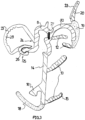
- FIG. 1 The front vehicle door 1 shown with a window 2 has a retractable window pane 3 which, when the window is closed, upper edge 4 is sealed against an upper frame part 5 of the window 2. A seal also exists between the upper frame part 5 and an edge surface of the door opening closed by the vehicle door 1 in a Fig. 1 vehicle body shown in detail 6.
- sealing lips 13 made of such a soft thermoplastic material protrude from an extension 14 of the outer U-leg of the U-shaped fastening section 8 or the inner U-leg of the U-shaped channel section 10.
- the sealing lips 12, 13 have, on their side facing the window pane 3, a sliding coating 15 made of a third thermoplastic material with suitable sliding properties.
- Adjoining the outer U-leg at the top is another sealing lip 20, which seals the upper frame part 5 against an edge surface 21 of the door opening in the vehicle body 6.
- the sealing lip 20 has, on its side facing the edge surface 21, a sliding coating 22 made of a sixth thermoplastic material with special sliding properties with respect to paint.
- the sealing lip 20 is otherwise made of the same material as the sealing lips 12, 13.
- the sliding coating 22 is a flocking layer.
- the inner U-leg of the U-shaped fastening section 8 is connected to a tubular sealing section 23, which serves to further seal the upper frame part 5 against the vehicle body 6 and rests against the edge surface 21 of the door opening.
- the sealing section 23 is made of a special thermoplastic material that withstands dynamic stresses to a particularly high degree.
- the sealing profile 7 described above which in the example shown has a curved shape in adaptation to the upper frame part 5, is produced by multiple extrusion and subsequent bending of the cooling extrudate, wherein the various profile sections consisting of different thermoplastic materials are joined together by extrusion.
- the wall of the tubular sealing section 23 is only integrally connected at 24 to the inner U-leg of the U-shaped fastening section 8, while at 25 a snap-in form-locking connection is established.
- the wall of the sealing section 23 is extruded onto the inner U-leg of the U-shaped fastening section 8 and onto an end piece 26, which is also made of the solid thermoplastic material of the U-shaped fastening section 8.
- the form-locking connection is necessary because an already closed extruded tubular sealing section could not be subjected to subsequent bending.
- the wall of the tubular sealing section 23 is designed with varying degrees of flexibility over the circumference of the hose by means of an area with notched grooves 28, such that a desired hose shape is achieved when the form-fitting connection 25 is produced.
- the fastening section 8, the channel section 10 and the end piece 26 can be made of the same hard thermoplastic material, e.g. PP ionomer, PP copolymer or glass fiber reinforced PP.
- soft thermoplastic material with a hardness between 55 and 75A can be considered, e.g. TPV or TPS.
- the extension 14 with the stop 16 is preferably made of a soft thermoplastic material with a hardness between 75 and 90A.
- thermoplastic material with a hardness between 35 and 50A can be considered.
- Both the extension 14 and the sealing section 23, like the sealing lips 12, 13, 20, can have TPV or TPS as base material.
- the decorative strip sections 18 and 19 consist of a material forming a decorative, scratch-resistant surface with a hardness between 55 and 90A, e.g. of TPV, TPS, PP, PA, an alloy of PA and PP or an ionomer.
- Reference numeral 27 denotes a metal insert, formed in the example in question as an aluminum strip, which is embedded in the hard material of the fastening section 8 or groove section 10.
- the metal insert 27 serves to limit the thermal expansion of the sealing profile 7 and, in the example shown, is arranged in a central region of the sealing strip section formed from the hard material.
Landscapes
- Engineering & Computer Science (AREA)
- Mechanical Engineering (AREA)
- Seal Device For Vehicle (AREA)
Description
- Die Erfindung betrifft eine Dichtung zwischen einem Rahmenteil eines Fahrzeugtürfensters und dem oberen Rand einer versenkbaren Scheibe des Fahrzeugtürfensters.
- Gemäß
Fig. 4 umfassen bekannte Dichtungen solcher Art ein Dichtungsprofil 7' aus EPDM- oder TPE-Material mit einer inFig. 4 gepunktet dargestellten Querschnittsfläche. Das Dichtungsprofil 7' ist auf einen Flansch 9' aufgesteckt, der von einem oberen, inFig. 4 im Querschnitt gezeigten Rahmenteil 5' senkrecht zur Ebene einer versenkbaren Fensterscheibe 3' vorsteht. Das Dichtungsprofil 7' weist ferner Dichtungslippen 20' auf, durch welche der obere Rahmenteil 5' gegen eine Randfläche 21' einer Türöffnung in einer Fahrzeugkarosserie 6' abdichtbar ist. - Aus
US 5,209,019 ist eine Dichtung bekannt, welche ein Dichtungsprofil aus Kunststoff umfasst, das auf einen von einem Türrahmen nach oben vorstehenden Flansch aufgesteckt ist. AusEP 0021069 A1 ,EP 1500542 A1 undWO 03/070501 A1 EP 0654371 A1 undDE 3512973 A1 sind Dichtungen zur Abdichtung eines Rahmenteils eines Fahrzeugtürfensters gegenüber dem oberen Rand einer versenkbaren Fensterscheibe des Fahrzeugtürfensters bekannt, wobei zusätzlich ein schlauchförmiges Dichtungsprofil zur Bildung einer Dichtung zwischen dem Rahmenteil und einer Randfläche einer Türöffnung in einer Fahrzeugkarosserie vorgesehen ist. - Gegenüber diesem Stand der Technik wird durch die vorliegende Erfindung eine neue Dichtung der eingangs genannten Art mit einem Dichtungsprofil geschaffen, das sich bei vereinfachter Konstruktion des das Dichtungsprofil aufnehmenden oberen Rahmenteils des Fahrzeugtürfensters mit geringerem Aufwand als herkömmliche EPDM- oder TPE-Dichtungsprofile positionssicher am oberen Rahmenteil montieren lässt und das darüber hinaus eine deutliche Materialkosten- und Gewichtsersparnis mit sich bringt.
- Diese Aufgabe wird durch eine Dichtung mit den Merkmalen des Anspruchs 1 gelöst.
- Vorteilhaft lässt sich das Dichtungsprofil der Dichtung nach der Erfindung mit geringem Aufwand über einen U-förmigen Befestigungsabschnitt auf den Flansch aufstecken, wobei eine Biegung des oberen Rahmenteils und eine dem Flanschverlauf entsprechende Biegung des Dichtungsprofils für dessen sicheren Sitz auf dem Flansch sorgen können. Der Sitz lässt keine Verschiebung des Dichtungsprofils in Flanschlängsrichtung zu. Vorteilhaft kann so das Dichtungsprofil auch noch eine Türdichtung bilden, für die nach dem Stand der Technik ein gesondertes Dichtungsprofil erforderlich ist.
- In einer bevorzugten Ausführungsform der Erfindung bildet ein äußerer U-Schenkel des U-förmigen Befestigungsabschnitts einen inneren Schenkel eines U-förmigen, den oberen Rand der Fensterscheibe aufnehmenden Rinnenabschnitts, wobei der genannte U-Schenkel den oberen Rand der Fensterscheibe von dem vertikal vorstehenden Flansch des oberen Rahmenteils fernhält.
- Erfindungsgemäß ist der innere Schenkel des U-förmigen Befestigungsabschnitts mit dem Dichtungsabschnitt zur Bildung einer Dichtung zwischen dem oberen Rahmenteil und einer Randfläche einer Türöffnung in der Fahrzeugkarosserie verbunden.
- Bei dem genannten Dichtungsabschnitt handelt es sich um einen schlauchförmigen Dichtungsabschnitt, der sich bei geschlossener Fahrzeugtür einer Türrahmenrandfläche anpasst und abdichtend gegen die Türrahmenrandfläche anliegt.
- In einer weiteren Ausführungsform der Erfindung erstreckt sich vom oberen Ende des äußeren U-Profilschenkels des U-förmigen Rinnenabschnitts nach oben ein Dichtungsabschnitt, insbesondere eine Dichtungslippe, die für eine weitere Abdichtung des oberen Rahmenteils des Fahrzeugtürfensters gegen die Randfläche der Türöffnung in der Karosserie sorgt.
- In einer besonders bevorzugten Ausführungsform der Erfindung, ist der den inneren U-Schenkel des Rinnenprofils bildende äußere U-Schenkel des Befestigungsabschnitts nach unten verlängert.
- Diese Verlängerung weist zweckmäßig an ihrem freien Ende einen den Rahmenteil untergreifenden Zierleistenabschnitt auf. Neben an der Fensterscheibe anliegenden Dichtungslippen können an der Verlängerung ferner auf der den Dichtungslippen abgewandten Seite Einrichtungen zur weiteren Verbindung des Dichtungsprofils mit dem Rahmenschenkel angebracht sein, insbesondere ein Anschlagvorsprung.
- In weiterer Ausgestaltung der Erfindung umfasst der äußere U-Schenkel des Rinnenabschnitts einen weiteren Zierleistenabschnitt.
- In einer weiteren besonders bevorzugten Ausführungsform der Erfindung ist das Dichtungsprofil aus verschiedenen Thermoplasten hergestellt. Es versteht sich, dass z.B. der Befestigungsabschnitt aus einem besonders festen Thermoplastmaterial hergestellt ist, das die für diesen Abschnitt erforderlichen Träger-und Klemmfunktionen übernehmen kann. Dichtungslippen sind dagegen aus einem flexiblen Thermoplastmaterial, Zierleistenabschnitte aus entsprechend attraktive Oberflächen bildendem Thermoplastmaterial hergestellt.
- In weiterer Ausgestaltung der Erfindung ist der Rinnenabschnitt wenigstens teilweise aus dem festen Thermoplastmaterial des Befestigungsabschnitts gebildet, so dass er große, durch den oberen Rand der Fensterscheibe übertragene Kräfte aufnehmen kann.
- Die Herstellung des Dichtungsprofils erfolgt vorzugweise durch Mehrfachextrusion und anschließende Biegebearbeitung des Extrudats, so dass der Biegung oberer Rahmenteile entsprechend gebogene, biegungsfrei montierbare Dichtungsprofile entstehen.
- Die Erfindung wird nachfolgend anhand eines Ausführungsbeispiels und der beiliegenden, sich auf dieses Ausführungsbeispiel beziehenden Zeichnungen weiter erläutert. Es zeigen:
- Fig. 1
- eine die Anordnung einer erfindungsgemäßen Dichtung an einem Fahrzeug erläuternde Darstellung,
- Fig. 2
- eine Dichtung nach der Erfindung in einer Querschnittsansicht,
- Fig. 3
- ein Dichtungsprofil der Dichtung von
Fig. 2 , und - Fig. 4
- eine gattungsgemäße Dichtung nach dem Stand der Technik.
- Eine in
Fig. 1 gezeigte vordere Fahrzeugtür 1 mit einem Fenster 2 weist eine versenkbare Fensterscheibe 3 auf, die im geschlossenen Zustand des Fensters mit ihrem oberen Rand 4 gegen einen oberen Rahmenteil 5 des Fensters 2 abgedichtet ist. Eine Abdichtung besteht ferner zwischen dem oberen Rahmenteil 5 und einer Randfläche der durch die Fahrzeugtür 1 verschlossenen Türöffnung in einer inFig. 1 ausschnittsweise gezeigten Fahrzeugkarosserie 6. - Wie aus
Fig. 2 hervorgeht, dient zur Abdichtung ein Dichtungsprofil 7, dass über einen U-förmigen Befestigungsabschnitt 8 auf einen Flansch 9 des inFig. 2 im Querschnitt gezeigten oberen Rahmenteils 5 aufgesteckt ist. Der Befestigungsabschnitt 8 besteht aus einem festen Thermoplastmaterial, dass eine Tragfunktion für weitere Profilabschnitte übernehmen sowie die zur Befestigung des Dichtungsprofils 7 an dem Flansch 9 erforderliche Klemmkraft aufbringen kann. - Wie die
Fig. 2 und3 zeigen, bildet das feste Thermoplastmaterial des U-förmigen Befestigungsabschnitts 8 einen wesentlichen Teil eines weiteren U-förmigen Profilabschnitts, nämlich eines Rinnenabschnitts 10, der eine Aufnahmerinne 11 für den oberen Rand 4 der Fensterscheibe 3 bildet. Der äußere U-Schenkel des U-förmigen Befestigungsabschnitts 8 ist sowohl Bestandteil des Befestigungsabschnitts 8 als auch des U-förmigen Rinnenabschnitts 10. Jeder der U-Schenkel des U-förmigen Rinnenabschnitts 10 weist eine Dichtungslippe 12 auf, wobei die Dichtungslippen 12 jeweils aus einem gegenüber dem festen Thermoplastmaterial des Befestigungsabschnitts 8 weicheren Thermoplastmaterial bestehen. - Weitere Dichtungslippen 13 aus solchem weichen Thermoplastmaterial stehen von einer Verlängerung 14 des äußeren U-Schenkels des U-förmigen Befestigungsabschnitts 8 bzw. inneren U-Schenkel des U-förmigen Rinnenabschnitts 10 vor. Die Dichtungslippen 12,13 weisen auf ihrer der Fensterscheibe 3 zugewandten Seite eine Gleitbeschichtung 15 aus einem dritten Thermoplastmaterial mit geeigneten Gleiteigenschaften auf.
- Die Verlängerung 14 selbst besteht in dem gezeigten Beispiel aus einem vierten Thermoplastmaterial, das gegenüber dem Thermoplastmaterial des Befestigungsabschnitts 8 geminderten Festigkeitsanforderungen genügt. Auf der den Dichtungslippen 13 abgewandten Seite der Verlängerung 14 steht ein Anschlag 16 vor, welcher der Befestigung des Dichtungsprofils 7 an dem oberen Rahmenteil 5 dient und über welchen das Dichtungsprofil 7 an einem weiteren Flansch des oberen Rahmenteils 5 anliegt.
- An das freie Ende der Verlängerung 14 schließt sich ein Zierleistenabschnitt 18 an, der den Flansch 17 des oberen Rahmenteils verdeckt und aus einem fünften Thermoplastmaterial besteht, das eine optisch attraktive Sichtfläche bildet. Ein weiterer aus solchem Thermoplastmaterial bestehender Zierleistenabschnitt 19 ist mit dem äußeren U-Schenkel des Rinnenabschnitts 10 verbunden und bildet zudem einen Endabschnitt dieses äußeren U-Schenkels.
- An den äußeren U-Schenkel schließt sich nach oben eine weitere Dichtungslippe 20 an, durch welche der obere Rahmenteil 5 gegen eine Randfläche 21 der Türöffnung in der Fahrzeugkarosserie 6 abgedichtet ist. Die Dichtungslippe 20 weist auf ihrer der Randfläche 21 zugewandten Seite eine Gleitbeschichtung 22 aus einem sechsten Thermoplastmaterial mit besonderen Gleiteigenschaften gegenüber Lack auf. Die Dichtungslippe 20 besteht im Übrigen aus dem gleichen Material wie die Dichtungslippen 12,13. Bei der Gleitbeschichtung 22 handelt es sich in dem gezeigten Beispiel um eine Beflockungsschicht.
- Der innere U-Schenkel des U-förmigen Befestigungsabschnitts 8 ist mit einem schlauchförmigen Dichtungsabschnitt 23 verbunden, welcher der weiteren Abdichtung des oberen Rahmenteils 5 gegen die Fahrzeugkarosserie 6 dient und gegen die Randfläche 21 der Türöffnung zur Anlage kommt. Der Dichtungsabschnitt 23 besteht aus einem siebenten Thermoplastmaterial, das in besondere, Maße dynamischen Beanspruchungen widersteht.
- Das vorangehend beschriebene Dichtungsprofil 7, das in dem gezeigten Beispiel in Anpassung an den oberen Rahmenteil 5 eine gebogene Form aufweist, ist durch Mehrfachextrusion und anschießende Biegebearbeitung des abkühlenden Extrudats hergestellt, wobei die verschiedenen, aus unterschiedlichen Thermoplastmaterialien bestehenden Profilabschnitte durch Aneinanderextrudieren stoffschlüssig miteinander verbunden werden.
- Die Wand des schlauchförmigen Dichtungsabschnitts 23 ist nur bei 24 stoffschlüssig mit dem inneren U-Schenkel des U-förmigen Befestigungsabschnitts 8 verbunden, bei 25 ist hingegen eine eingerastete Formschlussverbindung hergestellt. Die Wand des Dichtungsabschnitts 23 ist an den inneren U-Schenkel des U-förmigen Befestigungsabschnitts 8 sowie an ein Endstück 26 anextrudiert, das ebenfalls aus dem festen Thermoplastmaterial des U-förmigen Befestigungsabschnitts 8 besteht. Die Formschlussverbindung ist notwendig, weil sich ein bereits geschlossen extrudierter schlauchförmiger Dichtungsabschnitt keiner nachträglichen Biegebearbeitung unterziehen ließe. Die Wand des schlauchförmigen Dichtungsabschnitts 23 ist durch einen Bereich mit Einkerbungsrinnen 28 über den Schlauchumfang unterschiedlich flexibel derart ausgebildet, dass sich bei Herstellung der Formschlussverbindung 25 eine gewünschte Schlauchform einstellt.
- Der Befestigungsabschnitt 8, der Rinnenabschnitt 10 und das Endstück 26 können aus dem gleichen harten Thermoplastmaterial bestehen, z.B. PP-Ionomer, PP-Copolymer oder glasfaserverstärktem PP.
- Für die Dichtungslippen 12,13 und 20 kommt jeweils weiches Thermoplastmaterial mit einer Härte zwischen 55 und 75A in Betracht, z.B. TPV oder TPS.
- Die Verlängerung 14 mit dem Anschlag 16 besteht vorzugsweise aus einem weichen Thermoplastmaterial mit einer Härte zwischen 75 und 90A.
- Für den Dichtungsabschnitt 23 kommt ein sehr weiches Thermoplastmaterial mit einer Härte zwischen 35 und 50A in Betracht.
- Sowohl die Verlängerung 14 als auch der Dichtungsabschnitt 23 können wie die Dichtungslippen 12, 13, 20 als Basismaterial TPV oder TPS aufweisen.
- Die Zierleistenabschnitte 18 und 19 bestehen aus einem eine dekorative, kratzfeste Oberfläche bildenden Material mit einer Härte zwischen 55 und 90A, z.B. aus TPV, TPS, PP, PA, einer Legierung aus PA und PP oder einem lonomer.
- Mit 27 ist eine in dem betreffenden Beispiel als Aluminiumstreifen ausgebildete Metalleinlage bezeichnet, die in das harte Material des Befestigungsabschnitts 8 bzw. Rinnenabschnitts 10 eingebettet ist. Die Metalleinlage 27 dient zur Begrenzung der Wärmeausdehnung des Dichtungsprofils 7 und ist in dem gezeigten Beispiel in einem zentralen Bereich des aus dem harten Material gebildeten Dichtungsstrangabschnitts angeordnet.
- Der Herstellungsprozess des vorangehend beschriebenen Dichtungsstrangs erfordert zumindest fünf verschiedene Extrusionseinrichtungen, um die Dichtungsabschnitte aneinander zu extrudieren. Vorzugsweise werden sechs verschiedene Extruder eingesetzt.
Claims (11)
- Dichtung zwischen einem Rahmenteil (5) eines Fahrzeugtürfensters (2) und dem oberen Rand (4) einer versenkbaren Fensterscheibe (3) des Fahrzeugtürfensters (2), mit einem Dichtungsprofil (7) aus Kunststoff, das auf einen von dem Rahmenteil (5) des Fahrzeugtürfensters (2) nach oben vorstehenden Flansch (9) über einen U-förmigen Befestigungsabschnitt (8) aufgesteckt ist, wobei zusätzlich das Dichtungsprofil (7) mit einem schlauchförmigen Dichtungsabschnitt (23) zur Bildung einer Dichtung zwischen dem Rahmenteil (5) und einer Randfläche (21) einer Türöffnung in einer Fahrzeugkarosserie (6) vorgesehen ist,
dadurch gekennzeichnet,
dass der Dichtungsabschnitt (23) mit einem inneren Schenkel des U-förmigen Befestigungsabschnitts (8) verbunden ist, wobei eine Wand des schlauchförmigen Dichtungsabschnitts (23) im Querschnitt an einem ersten Ende an den inneren Schenkel anextrudiert ist und an einem entgegengesetzten Ende eine eingerastete Formschlussverbindung mit dem inneren U-Schenkel des U-förmigen Befestigungsabschnitts (8) hergestellt ist. - Dichtung nach Anspruch 1,
dadurch gekennzeichnet,
dass ein äußerer U-Schenkel des U-förmigen Befestigungsabschnitts (8) als innerer U-Schenkel eines U-förmigen, eine Aufnahmerinne (11) für den oberen Rand (4) der Fensterscheibe (3) bildenden Rinnenabschnitts (10) dient. - Dichtung nach Anspruch 1 oder 2,
dadurch gekennzeichnet,
dass das Dichtungsprofil (7) eine die Wärmeausdehnung begrenzende Metalleinlage (27) aufweist. - Dichtung nach Anspruch 2 oder 3,
dadurch gekennzeichnet,
dass von sich vom oberen Ende eines äußeren U-Profilschenkels des U-förmigen Rinnenabschnitts (10) nach oben ein Dichtungsabschnitt, insbesondere eine Dichtungslippe (20), erstreckt. - Dichtung nach einem der Ansprüche 2 bis 4,
dadurch gekennzeichnet,
dass den inneren U-Profilschenkel des Rinnenabschnitts (10) bildende äußere Schenkel des Befestigungsabschnitts (8) nach unten verlängert ist. - Dichtung nach Anspruch 4 oder 5,
dadurch gekennzeichnet,
dass die Verlängerung (14) an ihrem freien Ende mit einem den Rahmenteil (5) untergreifenden Zierleistenabschnitt (18) verbunden ist. - Dichtung nach Anspruch 6,
dadurch gekennzeichnet,
dass die Verlängerung (14) neben die Fensterscheibe (3) abdichtenden Dichtungslippen (13) Einrichtungen zur Verbindung mit dem Rahmenteil (5), insbesondere einen Anschlagvorsprung (16), aufweist. - Dichtung nach einem der Ansprüche 2 bis 7,
dadurch gekennzeichnet,
dass der äußere U-Schenkel des Rinnenabschnitts (10) einen Zierleistenabschnitt (19) umfasst. - Dichtung nach einem der Ansprüche 1 bis 8,
dadurch gekennzeichnet,
dass das Dichtungsprofil (7) aus verschiedenen Thermoplastmaterialien hergestellt ist. - Dichtung nach Anspruch 9,
dadurch gekennzeichnet,
dass der Rinnenabschnitt (10) wenigstens teilweise aus dem Thermoplastmaterial besteht, aus welchem der Befestigungsabschnitt (8) hergestellt ist. - Dichtung nach einem der Ansprüche 1 bis 10,
dadurch gekennzeichnet,
dass das Dichtungsprofil (7) durch Mehrfachextrusion und anschließende Biegebearbeitung des Extrudats gebildet ist.
Applications Claiming Priority (2)
| Application Number | Priority Date | Filing Date | Title |
|---|---|---|---|
| DE102016110276.8A DE102016110276A1 (de) | 2016-06-03 | 2016-06-03 | Dichtung für eine versenkbare Fensterscheibe eines Fahrzeugtürfensters |
| PCT/EP2017/000372 WO2017207076A1 (de) | 2016-06-03 | 2017-03-27 | Dichtung für eine versenkbare fensterscheibe eines fahrzeugtürfensters |
Publications (2)
| Publication Number | Publication Date |
|---|---|
| EP3463952A1 EP3463952A1 (de) | 2019-04-10 |
| EP3463952B1 true EP3463952B1 (de) | 2025-07-09 |
Family
ID=58544897
Family Applications (1)
| Application Number | Title | Priority Date | Filing Date |
|---|---|---|---|
| EP17717078.4A Active EP3463952B1 (de) | 2016-06-03 | 2017-03-27 | Dichtung für eine versenkbare fensterscheibe eines fahrzeugtürfensters |
Country Status (6)
| Country | Link |
|---|---|
| US (1) | US11117455B2 (de) |
| EP (1) | EP3463952B1 (de) |
| CN (1) | CN109070711B (de) |
| DE (1) | DE102016110276A1 (de) |
| ES (1) | ES3039435T3 (de) |
| WO (1) | WO2017207076A1 (de) |
Families Citing this family (6)
| Publication number | Priority date | Publication date | Assignee | Title |
|---|---|---|---|---|
| DE102017112720A1 (de) * | 2017-06-09 | 2018-12-13 | Cqlt Saargummi Technologies S.À.R.L. | Dichtungsanordnung |
| DE102018110218A1 (de) * | 2017-06-12 | 2018-12-13 | Cqlt Saargummi Technologies S.À.R.L. | Dichtungsanordnung zur Führung und Abdichtung einer vertikal bewegbaren Fahrzeugfensterscheibe |
| US11111003B2 (en) * | 2019-05-17 | 2021-09-07 | The Boeing Company | Aeroseal and method of forming the same |
| JP7188314B2 (ja) * | 2019-08-02 | 2022-12-13 | 豊田合成株式会社 | ガラスラン |
| US12358349B2 (en) | 2021-09-30 | 2025-07-15 | Magna Mirrors Of America, Inc. | Vehicle window assembly with bonded perimeter frame |
| DE102023103888A1 (de) * | 2023-02-16 | 2024-08-22 | Cqlt Saargummi Technologies S.À.R.L. | Dichtungsprofil für ein Kraftfahrzeug, Dichtungsanordnung und Verfahren zur Herstellung eines Dichtungsprofils |
Citations (2)
| Publication number | Priority date | Publication date | Assignee | Title |
|---|---|---|---|---|
| DE3512973A1 (de) * | 1984-05-08 | 1985-11-14 | Volkswagenwerk Ag, 3180 Wolfsburg | Fensterfuehrungsprofil |
| EP0654371A1 (de) * | 1993-11-15 | 1995-05-24 | METZELER Automotive Profiles GmbH | Anordnung zum gleichzeitigen Abdichten einer Türscheibe und der Türöffnung an einem Kraftfahrzeug |
Family Cites Families (25)
| Publication number | Priority date | Publication date | Assignee | Title |
|---|---|---|---|---|
| EP0021069B1 (de) * | 1979-06-15 | 1982-10-13 | AUDI NSU AUTO UNION Aktiengesellschaft | Scheibenführung in einem Fahrzeug |
| DE3210468A1 (de) * | 1982-03-22 | 1983-09-29 | Ymos-Metallwerke Wolf & Becker Gmbh & Co, 6053 Obertshausen | Tuer- und fensterrahmen |
| DE3227153A1 (de) * | 1982-07-21 | 1984-02-02 | Ford-Werke AG, 5000 Köln | Fahrzeugtuer, insbesondere fuer personenkraftwagen |
| IT8354039V0 (it) * | 1983-12-14 | 1983-12-14 | S I R P Societa Ind Realizzazi | Guarnizione per porta di autoveicoli |
| GB2223258B (en) * | 1988-09-30 | 1992-04-22 | Draftex Ind Ltd | Sealing and retaining strips |
| US5209019A (en) * | 1990-09-27 | 1993-05-11 | Tokai Kogyo Kabushiki Kaisha | Seal structure for automobile doors |
| US5317835A (en) * | 1992-09-10 | 1994-06-07 | Gencorp Inc. | Window enclosure for an automotive upper door frame |
| US5493814A (en) * | 1994-04-18 | 1996-02-27 | The Standard Products Company | Weatherstrip assembly including a glass run channel and belt weatherstrip with decorative cover |
| US5548929A (en) * | 1994-12-02 | 1996-08-27 | The Standard Products Company | Window sealing assembly |
| JPH0911813A (ja) * | 1995-06-28 | 1997-01-14 | Nishikawa Rubber Co Ltd | ドアの室内側外観向上構造 |
| GB2359320B (en) * | 2000-01-18 | 2003-11-19 | Draftex Ind Ltd | Sealing arrangements |
| DE20221602U1 (de) * | 2002-02-22 | 2006-07-20 | Metzeler Automotive Profile Systems Gmbh | Dichtungsanordnung, insbesondere zum Abdichten einer Tür gegenüber der Karosserie eines Kraftfahrzeugs |
| DE10207682C5 (de) | 2002-02-22 | 2008-08-28 | Metzeler Automotive Profile Systems Gmbh | Dichtungsanordnung zum Abdichten einer Tür gegenüber der Karosserie eines Kraftfahrzeugs |
| JP2004123007A (ja) * | 2002-10-04 | 2004-04-22 | Toyoda Gosei Co Ltd | 自動車のドアシール構造 |
| DE10313601B4 (de) * | 2003-03-26 | 2008-02-14 | Metzeler Automotive Profile Systems Gmbh | Dichtungsanordnung zum Abdichten und Führen einer bewegbaren Fensterscheibe, insbesondere eines Kraftfahrzeugs |
| DE10334065B4 (de) | 2003-07-25 | 2005-06-23 | Metzeler Automotive Profile Systems Gmbh | Dichtungsanordnung, insbesondere zum Abdichten einer feststehenden Fensterscheibe eines Kraftfahrzeugs |
| JP4809119B2 (ja) * | 2006-05-12 | 2011-11-09 | 西川ゴム工業株式会社 | ガラスランの取付構造 |
| US8166708B2 (en) | 2008-07-30 | 2012-05-01 | Ellis Peter J | Integrated glass run and upper reveal with film |
| DE102010056385A1 (de) * | 2010-12-28 | 2012-01-19 | Gm Global Technology Operations Llc, ( N.D. Ges. D. Staates Delaware) | Fahrzeugtür mit einer Säulenblende |
| US9114693B2 (en) * | 2012-05-04 | 2015-08-25 | Srg Global, Inc. | Daylight opening system |
| KR20150054358A (ko) * | 2013-11-12 | 2015-05-20 | 현대자동차주식회사 | 자동차용 바디 웨더스트립 |
| JP6585952B2 (ja) * | 2015-07-28 | 2019-10-02 | 西川ゴム工業株式会社 | 自動車ドア用モールの取付構造 |
| CN109641512B (zh) * | 2016-08-17 | 2022-10-11 | 库博标准汽车配件有限公司 | 用于嵌入式车门结构的一体式玻璃滑槽和亮条组件 |
| DE102017102755A1 (de) * | 2017-02-13 | 2018-08-16 | Cqlt Saargummi Technologies S.À.R.L. | Dichtungselement mit Verblendleiste |
| DE102017112720A1 (de) * | 2017-06-09 | 2018-12-13 | Cqlt Saargummi Technologies S.À.R.L. | Dichtungsanordnung |
-
2016
- 2016-06-03 DE DE102016110276.8A patent/DE102016110276A1/de active Pending
-
2017
- 2017-03-27 EP EP17717078.4A patent/EP3463952B1/de active Active
- 2017-03-27 ES ES17717078T patent/ES3039435T3/es active Active
- 2017-03-27 WO PCT/EP2017/000372 patent/WO2017207076A1/de not_active Ceased
- 2017-03-27 US US16/305,145 patent/US11117455B2/en active Active
- 2017-03-27 CN CN201780028384.XA patent/CN109070711B/zh active Active
Patent Citations (2)
| Publication number | Priority date | Publication date | Assignee | Title |
|---|---|---|---|---|
| DE3512973A1 (de) * | 1984-05-08 | 1985-11-14 | Volkswagenwerk Ag, 3180 Wolfsburg | Fensterfuehrungsprofil |
| EP0654371A1 (de) * | 1993-11-15 | 1995-05-24 | METZELER Automotive Profiles GmbH | Anordnung zum gleichzeitigen Abdichten einer Türscheibe und der Türöffnung an einem Kraftfahrzeug |
Also Published As
| Publication number | Publication date |
|---|---|
| US11117455B2 (en) | 2021-09-14 |
| EP3463952A1 (de) | 2019-04-10 |
| CN109070711B (zh) | 2022-03-04 |
| CN109070711A (zh) | 2018-12-21 |
| DE102016110276A1 (de) | 2017-12-07 |
| ES3039435T3 (en) | 2025-10-21 |
| US20200317036A1 (en) | 2020-10-08 |
| WO2017207076A1 (de) | 2017-12-07 |
Similar Documents
| Publication | Publication Date | Title |
|---|---|---|
| DE69403296T3 (de) | Dichtungselement für flachmontiertes Fenster | |
| WO2017207076A1 (de) | Dichtung für eine versenkbare fensterscheibe eines fahrzeugtürfensters | |
| EP0853556B1 (de) | Dichtungsanordnung für kraftfahrzeuge | |
| DE7001383U (de) | U-foermig profilierte fensterfuehrung. | |
| DE102010001468B4 (de) | Verfahren zur Herstellung einer Dichtung | |
| DE9006595U1 (de) | Abdicht- und Führungsvorrichtung für ein eine verschiebbare Fensterscheibe aufweisendes Fenster | |
| EP1534548B1 (de) | Dichtungsprofil | |
| DE202008014739U1 (de) | Dichtungsanordnung für den Fensterschacht einer Fahrzeugtüre | |
| DE202013000888U1 (de) | Vorrichtung zur Abdeckung eines in Längsrichtung eines Kraftfahrzeuges verlaufenden Dachkanals | |
| WO2009149905A1 (de) | Dichtungsprofil | |
| EP2792520B1 (de) | Dichtungsprofil und Türanordnung mit einem solchen Dichtungsprofil | |
| DE202007002233U1 (de) | Dekoratives Bauteil | |
| EP1603763A1 (de) | Dichtungsleiste für eine fahrzeugrahmenstruktur | |
| DE102008006545B4 (de) | Verfahren zur Herstellung einer Dichtung, insbesondere für ein Kraftfahrzeug und eine solche Dichtung | |
| EP1927493A2 (de) | Spriegelanordnung für ein Cabriolet-Fahrzeug | |
| DE102007059411B4 (de) | Dichtung zum Abdichten der Fensterscheibe eines Kraftfahrzeugs, Verstärkungsträger für eine solche Dichtung und Verfahren zum Herstellen der Dichtung | |
| EP3135962B1 (de) | Dichtelement | |
| DE102006027697B4 (de) | Dichtband | |
| DE69605125T2 (de) | Druckabdichtung | |
| DE102006009386A1 (de) | Dekorative Abdeckvorrichtung für eine spaltförmige Öffnung | |
| EP0170870B1 (de) | Verfahren zum Herstellen von Dichtungsprofilleisten | |
| DE69903209T2 (de) | Dichtungselement für Schiebefenster, insbesondere für eine Kraftfahrzeugtür und Verfahren zu deren Herstellung | |
| EP3652008B1 (de) | Halter für ein flächenelement einer sonnenschutz- oder verdunklungsvorrichtung und sonnenschutz- oder verdunklungsvorrichtung | |
| DE3239395A1 (de) | Profilleiste | |
| DE7803702U1 (de) | Spritz- oder Preßkörper |
Legal Events
| Date | Code | Title | Description |
|---|---|---|---|
| STAA | Information on the status of an ep patent application or granted ep patent |
Free format text: STATUS: UNKNOWN |
|
| STAA | Information on the status of an ep patent application or granted ep patent |
Free format text: STATUS: THE INTERNATIONAL PUBLICATION HAS BEEN MADE |
|
| PUAI | Public reference made under article 153(3) epc to a published international application that has entered the european phase |
Free format text: ORIGINAL CODE: 0009012 |
|
| STAA | Information on the status of an ep patent application or granted ep patent |
Free format text: STATUS: REQUEST FOR EXAMINATION WAS MADE |
|
| 17P | Request for examination filed |
Effective date: 20181119 |
|
| AK | Designated contracting states |
Kind code of ref document: A1 Designated state(s): AL AT BE BG CH CY CZ DE DK EE ES FI FR GB GR HR HU IE IS IT LI LT LU LV MC MK MT NL NO PL PT RO RS SE SI SK SM TR |
|
| AX | Request for extension of the european patent |
Extension state: BA ME |
|
| DAV | Request for validation of the european patent (deleted) | ||
| DAX | Request for extension of the european patent (deleted) | ||
| STAA | Information on the status of an ep patent application or granted ep patent |
Free format text: STATUS: EXAMINATION IS IN PROGRESS |
|
| 17Q | First examination report despatched |
Effective date: 20210129 |
|
| GRAP | Despatch of communication of intention to grant a patent |
Free format text: ORIGINAL CODE: EPIDOSNIGR1 |
|
| STAA | Information on the status of an ep patent application or granted ep patent |
Free format text: STATUS: GRANT OF PATENT IS INTENDED |
|
| INTG | Intention to grant announced |
Effective date: 20250225 |
|
| GRAS | Grant fee paid |
Free format text: ORIGINAL CODE: EPIDOSNIGR3 |
|
| GRAA | (expected) grant |
Free format text: ORIGINAL CODE: 0009210 |
|
| STAA | Information on the status of an ep patent application or granted ep patent |
Free format text: STATUS: THE PATENT HAS BEEN GRANTED |
|
| AK | Designated contracting states |
Kind code of ref document: B1 Designated state(s): AL AT BE BG CH CY CZ DE DK EE ES FI FR GB GR HR HU IE IS IT LI LT LU LV MC MK MT NL NO PL PT RO RS SE SI SK SM TR |
|
| REG | Reference to a national code |
Ref country code: GB Ref legal event code: FG4D Free format text: NOT ENGLISH |
|
| REG | Reference to a national code |
Ref country code: CH Ref legal event code: EP |
|
| REG | Reference to a national code |
Ref country code: IE Ref legal event code: FG4D Free format text: LANGUAGE OF EP DOCUMENT: GERMAN |
|
| REG | Reference to a national code |
Ref country code: DE Ref legal event code: R096 Ref document number: 502017016954 Country of ref document: DE |
|
| REG | Reference to a national code |
Ref country code: ES Ref legal event code: FG2A Ref document number: 3039435 Country of ref document: ES Kind code of ref document: T3 Effective date: 20251021 |
|
| REG | Reference to a national code |
Ref country code: NL Ref legal event code: MP Effective date: 20250709 |
|
| REG | Reference to a national code |
Ref country code: SK Ref legal event code: T3 Ref document number: E 47165 Country of ref document: SK |
|
| PG25 | Lapsed in a contracting state [announced via postgrant information from national office to epo] |
Ref country code: PT Free format text: LAPSE BECAUSE OF FAILURE TO SUBMIT A TRANSLATION OF THE DESCRIPTION OR TO PAY THE FEE WITHIN THE PRESCRIBED TIME-LIMIT Effective date: 20251110 |
|
| PG25 | Lapsed in a contracting state [announced via postgrant information from national office to epo] |
Ref country code: NL Free format text: LAPSE BECAUSE OF FAILURE TO SUBMIT A TRANSLATION OF THE DESCRIPTION OR TO PAY THE FEE WITHIN THE PRESCRIBED TIME-LIMIT Effective date: 20250709 |
|
| PG25 | Lapsed in a contracting state [announced via postgrant information from national office to epo] |
Ref country code: IS Free format text: LAPSE BECAUSE OF FAILURE TO SUBMIT A TRANSLATION OF THE DESCRIPTION OR TO PAY THE FEE WITHIN THE PRESCRIBED TIME-LIMIT Effective date: 20251109 |
|
| PG25 | Lapsed in a contracting state [announced via postgrant information from national office to epo] |
Ref country code: NO Free format text: LAPSE BECAUSE OF FAILURE TO SUBMIT A TRANSLATION OF THE DESCRIPTION OR TO PAY THE FEE WITHIN THE PRESCRIBED TIME-LIMIT Effective date: 20251009 |
|
| REG | Reference to a national code |
Ref country code: LT Ref legal event code: MG9D |
|
| PG25 | Lapsed in a contracting state [announced via postgrant information from national office to epo] |
Ref country code: FI Free format text: LAPSE BECAUSE OF FAILURE TO SUBMIT A TRANSLATION OF THE DESCRIPTION OR TO PAY THE FEE WITHIN THE PRESCRIBED TIME-LIMIT Effective date: 20250709 |
|
| PG25 | Lapsed in a contracting state [announced via postgrant information from national office to epo] |
Ref country code: HR Free format text: LAPSE BECAUSE OF FAILURE TO SUBMIT A TRANSLATION OF THE DESCRIPTION OR TO PAY THE FEE WITHIN THE PRESCRIBED TIME-LIMIT Effective date: 20250709 |
|
| PG25 | Lapsed in a contracting state [announced via postgrant information from national office to epo] |
Ref country code: GR Free format text: LAPSE BECAUSE OF FAILURE TO SUBMIT A TRANSLATION OF THE DESCRIPTION OR TO PAY THE FEE WITHIN THE PRESCRIBED TIME-LIMIT Effective date: 20251010 |
|
| PG25 | Lapsed in a contracting state [announced via postgrant information from national office to epo] |
Ref country code: SE Free format text: LAPSE BECAUSE OF FAILURE TO SUBMIT A TRANSLATION OF THE DESCRIPTION OR TO PAY THE FEE WITHIN THE PRESCRIBED TIME-LIMIT Effective date: 20250709 |
|
| PG25 | Lapsed in a contracting state [announced via postgrant information from national office to epo] |
Ref country code: LV Free format text: LAPSE BECAUSE OF FAILURE TO SUBMIT A TRANSLATION OF THE DESCRIPTION OR TO PAY THE FEE WITHIN THE PRESCRIBED TIME-LIMIT Effective date: 20250709 |
|
| PG25 | Lapsed in a contracting state [announced via postgrant information from national office to epo] |
Ref country code: PL Free format text: LAPSE BECAUSE OF FAILURE TO SUBMIT A TRANSLATION OF THE DESCRIPTION OR TO PAY THE FEE WITHIN THE PRESCRIBED TIME-LIMIT Effective date: 20250709 Ref country code: BG Free format text: LAPSE BECAUSE OF FAILURE TO SUBMIT A TRANSLATION OF THE DESCRIPTION OR TO PAY THE FEE WITHIN THE PRESCRIBED TIME-LIMIT Effective date: 20250709 |
|
| PG25 | Lapsed in a contracting state [announced via postgrant information from national office to epo] |
Ref country code: RS Free format text: LAPSE BECAUSE OF FAILURE TO SUBMIT A TRANSLATION OF THE DESCRIPTION OR TO PAY THE FEE WITHIN THE PRESCRIBED TIME-LIMIT Effective date: 20251009 |
|
| PG25 | Lapsed in a contracting state [announced via postgrant information from national office to epo] |
Ref country code: SM Free format text: LAPSE BECAUSE OF FAILURE TO SUBMIT A TRANSLATION OF THE DESCRIPTION OR TO PAY THE FEE WITHIN THE PRESCRIBED TIME-LIMIT Effective date: 20250709 |
|
| PG25 | Lapsed in a contracting state [announced via postgrant information from national office to epo] |
Ref country code: DK Free format text: LAPSE BECAUSE OF FAILURE TO SUBMIT A TRANSLATION OF THE DESCRIPTION OR TO PAY THE FEE WITHIN THE PRESCRIBED TIME-LIMIT Effective date: 20250709 |
|
| PGFP | Annual fee paid to national office [announced via postgrant information from national office to epo] |
Ref country code: DE Payment date: 20260319 Year of fee payment: 10 |
|
| PG25 | Lapsed in a contracting state [announced via postgrant information from national office to epo] |
Ref country code: IT Free format text: LAPSE BECAUSE OF FAILURE TO SUBMIT A TRANSLATION OF THE DESCRIPTION OR TO PAY THE FEE WITHIN THE PRESCRIBED TIME-LIMIT Effective date: 20250709 |
|
| PGFP | Annual fee paid to national office [announced via postgrant information from national office to epo] |
Ref country code: FR Payment date: 20260320 Year of fee payment: 10 |
|
| PGFP | Annual fee paid to national office [announced via postgrant information from national office to epo] |
Ref country code: CZ Payment date: 20260323 Year of fee payment: 10 |
|
| PG25 | Lapsed in a contracting state [announced via postgrant information from national office to epo] |
Ref country code: EE Free format text: LAPSE BECAUSE OF FAILURE TO SUBMIT A TRANSLATION OF THE DESCRIPTION OR TO PAY THE FEE WITHIN THE PRESCRIBED TIME-LIMIT Effective date: 20250709 |
|
| PGFP | Annual fee paid to national office [announced via postgrant information from national office to epo] |
Ref country code: SK Payment date: 20260324 Year of fee payment: 10 |
|
| PLBE | No opposition filed within time limit |
Free format text: ORIGINAL CODE: 0009261 |
|
| STAA | Information on the status of an ep patent application or granted ep patent |
Free format text: STATUS: NO OPPOSITION FILED WITHIN TIME LIMIT |