EP3462251A1 - Mécanisme de mise à l'heure pour mouvement horloger - Google Patents
Mécanisme de mise à l'heure pour mouvement horloger Download PDFInfo
- Publication number
- EP3462251A1 EP3462251A1 EP17193963.0A EP17193963A EP3462251A1 EP 3462251 A1 EP3462251 A1 EP 3462251A1 EP 17193963 A EP17193963 A EP 17193963A EP 3462251 A1 EP3462251 A1 EP 3462251A1
- Authority
- EP
- European Patent Office
- Prior art keywords
- locking
- wheel
- setting
- sliding pinion
- time
- Prior art date
- Legal status (The legal status is an assumption and is not a legal conclusion. Google has not performed a legal analysis and makes no representation as to the accuracy of the status listed.)
- Granted
Links
Images

Classifications
-
- G—PHYSICS
- G04—HOROLOGY
- G04B—MECHANICALLY-DRIVEN CLOCKS OR WATCHES; MECHANICAL PARTS OF CLOCKS OR WATCHES IN GENERAL; TIME PIECES USING THE POSITION OF THE SUN, MOON OR STARS
- G04B27/00—Mechanical devices for setting the time indicating means
- G04B27/02—Mechanical devices for setting the time indicating means by making use of the winding means
-
- G—PHYSICS
- G04—HOROLOGY
- G04B—MECHANICALLY-DRIVEN CLOCKS OR WATCHES; MECHANICAL PARTS OF CLOCKS OR WATCHES IN GENERAL; TIME PIECES USING THE POSITION OF THE SUN, MOON OR STARS
- G04B27/00—Mechanical devices for setting the time indicating means
-
- G—PHYSICS
- G04—HOROLOGY
- G04B—MECHANICALLY-DRIVEN CLOCKS OR WATCHES; MECHANICAL PARTS OF CLOCKS OR WATCHES IN GENERAL; TIME PIECES USING THE POSITION OF THE SUN, MOON OR STARS
- G04B27/00—Mechanical devices for setting the time indicating means
- G04B27/02—Mechanical devices for setting the time indicating means by making use of the winding means
- G04B27/04—Mechanical devices for setting the time indicating means by making use of the winding means with clutch wheel
- G04B27/045—Changing the winding position to the setting position and vice versa is done with an independant part of the winding or setting mechanism
-
- G—PHYSICS
- G04—HOROLOGY
- G04B—MECHANICALLY-DRIVEN CLOCKS OR WATCHES; MECHANICAL PARTS OF CLOCKS OR WATCHES IN GENERAL; TIME PIECES USING THE POSITION OF THE SUN, MOON OR STARS
- G04B13/00—Gearwork
-
- G—PHYSICS
- G04—HOROLOGY
- G04B—MECHANICALLY-DRIVEN CLOCKS OR WATCHES; MECHANICAL PARTS OF CLOCKS OR WATCHES IN GENERAL; TIME PIECES USING THE POSITION OF THE SUN, MOON OR STARS
- G04B27/00—Mechanical devices for setting the time indicating means
- G04B27/02—Mechanical devices for setting the time indicating means by making use of the winding means
- G04B27/04—Mechanical devices for setting the time indicating means by making use of the winding means with clutch wheel
-
- G—PHYSICS
- G04—HOROLOGY
- G04B—MECHANICALLY-DRIVEN CLOCKS OR WATCHES; MECHANICAL PARTS OF CLOCKS OR WATCHES IN GENERAL; TIME PIECES USING THE POSITION OF THE SUN, MOON OR STARS
- G04B3/00—Normal winding of clockworks by hand or mechanically; Winding up several mainsprings or driving weights simultaneously
- G04B3/04—Rigidly-mounted keys, knobs or crowns
-
- G—PHYSICS
- G04—HOROLOGY
- G04B—MECHANICALLY-DRIVEN CLOCKS OR WATCHES; MECHANICAL PARTS OF CLOCKS OR WATCHES IN GENERAL; TIME PIECES USING THE POSITION OF THE SUN, MOON OR STARS
- G04B37/00—Cases
- G04B37/06—Forming the passage for the winding stem through the case; Divided winding stems
- G04B37/062—Means for preventing the winding stem from being pulled out too far
- G04B37/064—Means for preventing the winding stem from being pulled out too far by a tirette
Definitions
- the present invention relates to a time-setting mechanism for a clockwork movement of a watch comprising a locking device of the time setting wheel in order to avoid a movement of the needles in the event of shocks.
- a friction system is generally provided for this purpose in order to guarantee an easy adjustment of the time while ensuring a reliable drive of the needles by the finishing gear during the running of the watch.
- a well-known friction system is the skylight which consists of adjusting the roadway on the center pinion shaft in order to obtain a "greasy friction" to allow time setting without causing the finishing gear.
- the thickness of the roadway is reduced in the middle and is pinched by means of a dedicated tool for this purpose so as to form a projection which press against a conical cut of the pinion shaft of the center.
- Lanterning is a delicate operation that requires careful control to ensure that the torque value generated by friction between the roadway and the center pinion shaft is optimal. Indeed, a low friction torque can cause, during shocks, a displacement of the needles due to their unbalance. By the way, a couple too strong may cause the deterioration of the time-setting train (idle-sprint-timer-gear) or the work train (center-medium-second-exhaust) during the time setting.
- the object of the present invention is to provide a time-setting mechanism in order, in particular, to overcome the disadvantages of the prior art mentioned above and to avoid any drift in the display of the time during shocks. important to the watch.
- the time setting mechanism further comprises a locking device of the time setting wheel.
- This locking device comprises a first and second locking arm and a locking wheel engaged with the time setting train.
- the first and second locking arms are arranged, on the one hand, to engage with the locking wheel in a so-called locked configuration in which the time setting gear is locked and, on the other hand, to be released from the locking wheel in a so-called unlocked configuration in which the sliding pinion is free to mesh with the time setting wheel.
- the blocking device comprises a latching / unlocking lever engaged with the sliding pinion and arranged to cooperate with the first and second locking arms in order to effect a transition from the locked configuration to the unlocked configuration and vice versa when the winding stem is brought from a running position to a setting position and vice versa.
- the locking wheel comprises a toothing whose apex of each tooth has a curved profile.
- the first and second locking arms each comprise a portion having a curved edge provided with a micro-tooth.
- the radius of curvature of the curved edge of the first and second locking arms substantially corresponds to the radius of the head circle of the locking wheel.
- These micro teeth are intended to come into contact with the toothing of the locking wheel in the locked configuration of the locking device.
- the particular profile of the toothing of the locking wheel and micro-teeth has the advantage of allowing an angular precision of locking of the wheel so that the deviation of the needles is negligible after correction of the time when the rod of winder is brought back into the walking position.
- the micro teeth of the first and second locking arms are symmetrical relative to each other so as to prevent rotation of the locking wheel in both directions.
- first and second locking arms are superposed and pivotally mounted relative to one another about a common axis.
- the curved edge of the lower or upper locking arm is respectively intended to come into contact with a lower or upper portion of the toothing of the locking wheel.
- one or both arms of blocking may include an extra thickness in the portion comprising the micro teeth arranged so as to provide support of the two arms of the same height on the locking wheel.
- the latching / unlocking latch is arranged to pivot about a pivot when the winding stem is brought from a running position to a setting position and vice versa.
- This latch / unlocking latch has two arms extending on either side of the pivot. One end of one of the two arms is engaged with the sliding pinion while the other of the two arms has a distal portion intended to cooperate with the upper locking arm and a proximal portion intended to cooperate with the lower locking arm.
- the distal portion bears against a straight flank of the upper locking arm.
- the proximal portion for its part, bears or is intended to bear against an actuating element, preferably a pin, of the lower locking arm in order to disengage the locking arms from the toothing of the locking wheel.
- an actuating element preferably a pin
- the locking wheel is the timer wheel of the time setting wheel.
- the locking wheel is mounted integral with the axis of a standard timer wheel of the time setting wheel.
- the time setting mechanism comprises, in a conventional manner, a pull tab 12 comprising a pin 12a housed in a recess of the winding stem 10, a rocker 14 arranged to cooperate with the pull tab 12, and a sliding pinion 16. It is fitted on a segment 17a of square cross section of a secondary rod 17 so as to be able to move along this segment 17a of a first axial position, in which the sliding pinion 16 is a socket with a pinion 18, at a second axial position, in which the sliding pinion 16 is engaged with a return 19 of the time-setting train as illustrated in FIG. figure 2b .
- the latch 14 has an end 14a arranged in a circular groove 16a of the sliding pinion 16.
- the pull tab 12 pivots and pushes back the rocker 14 which slides the sliding pinion 16 along the segment 17a of the secondary rod 17.
- the sliding pinion 16 thus disengages the pinion winding 18 to engage with the reference 19 of the time setting train for the control of the needles.
- the time setting mechanism further comprises a blocking device time setting.
- This device comprises a locking wheel 20 configured to cooperate on the one hand with the time setting train and secondly with a first and second locking arm 22, 30.
- the locking wheel 20 has a toothing whose apex of each tooth has a curved profile.
- This particular profile of the toothing of the blocking wheel 20 makes it possible, on the one hand, to maintain a toothing allowing meshing with the sliding pinion 16 via the returns for setting the time, in order to fulfill the function of a standard timer wheel, and on the other hand, to increase the angular accuracy of the locking by the first and second locking arms 22, 30.
- these latter each comprise a portion 28, 32 having a curved edge extending in an arc of an angle preferably between 30 ° and 40 °, whose radius of curvature essentially corresponds to the radius of the head circle of the locking wheel 20.
- the curved edges of the locking arms 22, 30 are provided with micro-teeth to increase the points of contact with the toothing of the locking wheel 20 when the curved edges are in contact with the latter. . This has the advantage of increasing the angular accuracy of the blockage.
- the first and second locking arms 22, 30 are also superimposed and pivotally mounted relative to each other around a post 36.
- the micro teeth of the upper locking arm 22 and the lower locking arm 30 are held against an upper portion, respectively lower of the toothing of the locking wheel 20 by a spring (220 and 300), when the locking device is in a locked configuration.
- These two micro-teeth have a symmetry with respect to an axis passing through the center of the locking wheel 20 and by the pivot axis of the two locking arms 22, 30. The two micro-teeth are therefore oriented in an opposite direction.
- the first locking arm 22 has a spout 26 provided with a straight blank 24 from the tip of the spout 26 to a corner 25 forming an obtuse angle.
- the second locking arm 30 comprises, meanwhile, a pin 34 extending vertically relative to the plane in which the second arm is arranged to pivot
- the blocking device of the time-setting train furthermore comprises a latch / unlocking latch 40 intended to lock and unlock the locking wheel 20.
- this latch / unlocking latch 40 is arranged to pivot around it.
- a post 46 and comprises two arms 42, 44 extending on either side of the post 46.
- One end of one of the two arms 42 is housed in the circular groove 16a of the sliding pinion 16 facing the end. 14a of the latch 14.
- the end of the arm 42 of the latch latch / unlocking 40 and the end 14a of the latch 14 are arranged on either side of a rod connecting the part sliding pinion 16 intended to mesh with the reference 19 and the part of the sliding pinion 16 intended to mesh with the winding pinion 18.
- the other of the two arms 44 of the latch / unlock latch 40 is similar to an angled arm having a distal portion 44a and a proximal portion 44b ( figure 2a ).
- the distal portion 44a has a pointed end located in the corner 45 of the first locking arm 22 when the locking device of the time-setting train is in a locked configuration.
- the proximal portion 44b is intended to abut against the pin 34 of the second locking arm 30 when the winding stem 10 is brought into a setting position.
- the blocking device of the time-setting train is in a locked configuration, that is to say the blocking wheel 20 is locked by the first and second locking arms 22, thus guaranteeing the blocking of the locking mechanism.
- clocking mechanism in case of big shocks on the watch and this during the normal running of the watch.
- the winding stem 10 When it is necessary to perform a time setting, the winding stem 10 is brought from a first axial position corresponding to a running position of the watch to a second axial position corresponding to a setting position. time of the watch.
- the axial displacement of the winding stem 10 actuates the pull rod 12 in rotation, which in turn actuates the rocker 14 so that its end 14a moves the sliding pinion 16 along the segment 17a of the secondary rod 17 of a first position axial, in which it is engaged with the winding pinion 18 at a second axial position, in which it is engaged with the reference 19 of the gear train time setting.
- the arms 42, 44 of the latch / unlock latch 40 pivot about the pin 46 counterclockwise under the action of the sliding pinion 16 on the end of the arm 42 when it moves from its position. first position at its second axial position.
- the pointed end of the distal portion 44a of the arm 44 will exert a stress on the rectilinear flank 24 of the first arm 22, while moving along this side 24 so that the first arm 22 pivots around the pin 36 so as to release the first micro gear of the locking wheel 20.
- the proximal portion 44b abuts against the pin 34 of the second locking arm 30 to release the second micro-teeth of the locking wheel 20.
- the locking device as illustrated in figure 2b is in an unlocked configuration and the time setting has the advantage of being able to be done without risk of damaging the finishing gear because, as mentioned above, the roadway is simply adjusted to the barrel of the minute wheel without any "Greasy friction".
- the winding stem 10 is returned to the first axial position, and the latch / unlocking lever 40 pivots around its peg 46 in a clockwise direction, which brings the arm 44 back into position. position illustrated in the figure 2a .
- the first and second coupling arms 22, 30 pivot about the pin 36 under the action of their respective return spring in order to bring and maintain their respective micro teeth against the toothing of the locking wheel 20 thus locking the locking device so that the watch is insensitive to any significant shocks.
- the locking wheel 20 could only perform the blocking function of the time setting wheel without fulfilling the function of the timer wheel. It could therefore have a locking wheel mounted to the axis of a standard timer wheel, and blocked by the two locking arms. The toothing of the locking wheel will then be solely dedicated to cooperate with the teeth of the locking arms and the number of teeth may be increased to improve the angular accuracy of the locking.
- the sliding pinion is adjusted to move on a segment of a secondary rod off-set relative to the winding stem.
- this construction is dictated by the constraints of a particular watchmaking movement.
Landscapes
- Physics & Mathematics (AREA)
- General Physics & Mathematics (AREA)
- Electromechanical Clocks (AREA)
- Measurement Of Predetermined Time Intervals (AREA)
- Transmission Devices (AREA)
- Mechanical Operated Clutches (AREA)
- Telephone Set Structure (AREA)
Abstract
Description
- La présente invention concerne un mécanisme de mise à l'heure pour un mouvement horloger d'une montre comportant un dispositif de blocage du rouage de la mise à l'heure afin d'éviter un déplacement des aiguilles en cas de chocs.
- Pendant la mise à l'heure, les aiguilles doivent pouvoir tourner facilement, sous l'action de la tige de remontoir, mais elles doivent aussi être entraînées sûrement, pendant la marche de la montre. Un système de friction est généralement prévu à cet effet afin de garantir un réglage facile de l'heure tout en assurant un entraînement fiable des aiguilles par le rouage de finissage au cours de la marche de la montre.
- Un système de friction bien connu est le lanternage qui consiste à ajuster la chaussée sur la tige du pignon du centre afin d'obtenir un « frottement gras » pour permettre la mise à l'heure sans entrainer le rouage de finissage. A cet effet, l'épaisseur de la chaussée est diminuée en son milieu et est pincée au moyen d'un outil dédié à cet effet de manière à former une saillie qui presse contre une entaille conique de la tige du pignon du centre.
- Le lanternage est toutefois une opération délicate qui demande un contrôle rigoureux pour s'assurer que la valeur du couple, engendré par la friction entre la chaussée et la tige du pignon du centre, est optimale. En effet, un couple de friction trop faible peut entraîner, lors de chocs, un déplacement des aiguilles dû à leur balourd. Par ailleurs, un couple trop fort peut engendrer la détérioration du rouage de mise à l'heure (pignon coulant-renvois-minuterie) ou du rouage de finissage (centre-moyenne-seconde-échappement) au cours de la mise à l'heure.
- Par conséquent, la présente invention a pour but de fournir un mécanisme de mise à l'heure afin notamment de pallier les inconvénients de l'état de la technique précités et d'éviter toute dérive de l'affichage de l'heure lors de chocs importants subis par la montre.
- A cet effet, le mécanisme de mise à l'heure pour mouvement horloger, comporte :
- un rouage de mise à l'heure,
- une tige de remontoir agencée pour être déplacée d'une première position axiale dite position de marche à une seconde position axiale dite position de mise à l'heure,
- un pignon coulant agencé pour être déplacé d'une première position axiale dans laquelle le pignon coulant est dégagé du rouage de mise à l'heure à une seconde position axiale dans laquelle le pignon coulant engrène avec le rouage de mise à l'heure, et
- une bascule en prise avec le pignon coulant et agencée pour pivoter, lorsque la tige de remontoir est amenée d'une position de marche à une position de mise à l'heure et inversement, afin d'amener le pignon coulant de la première à la seconde position axiale et inversement.
- Le mécanisme de mise à l'heure selon l'invention comporte en outre un dispositif de blocage du rouage de mise à l'heure. Ce dispositif de blocage comporte un premier et second bras de blocage et une roue de blocage en prise avec le rouage de mise à l'heure. Les premier et second bras de blocage sont agencés, d'une part, pour être en prise avec la roue de blocage dans une configuration dite verrouillée dans laquelle le rouage de mise à l'heure est bloqué et, d'autre part, pour être dégagés de la roue de blocage dans une configuration dite déverrouillée dans laquelle le pignon coulant est libre d'engrener avec le rouage de mise à l'heure. Le dispositif de blocage comporte à cet effet une bascule de verrouillage/déverrouillage en prise avec le pignon coulant et agencée pour coopérer avec les premier et second bras de blocage afin d'effectuer un passage de la configuration verrouillée à la configuration déverrouillée et inversement lorsque la tige de remontoir est amenée d'une position de marche à une position de mise à l'heure et inversement.
- Selon une forme de réalisation avantageuse, la roue de blocage comporte une denture dont le sommet de chaque dent présente un profil incurvé. Les premier et second bras de blocage comportent chacun une portion présentant un bord incurvé pourvu d'une micro denture. Le rayon de courbure du bord incurvé du premier et second bras de blocage correspond essentiellement au rayon du cercle de tête de la roue de blocage. Ces micro dentures sont destinées à venir au contact de la denture de la roue de blocage dans la configuration verrouillée du dispositif de blocage. Le profil particulier de la denture de la roue de blocage et des micro dentures à l'avantage de permettre une précision angulaire de blocage de la roue de manière à ce que la déviation des aiguilles est négligeable après correction de l'heure lorsque la tige de remontoir est ramenée dans la position de marche.
- Selon une forme de réalisation avantageuse, les micro dentures des premier et second bras de blocage sont symétriques l'une par rapport à l'autre de manière à empêcher toute rotation de la roue de blocage dans les deux sens.
- Selon une forme de réalisation avantageuse, les premier et second bras de blocage sont superposés et montés pivotants l'un par rapport à l'autre autour d'un axe commun. Le bord incurvé du bras de blocage inférieur, respectivement supérieur est destiné à venir au contact d'une portion inférieure, respectivement supérieure de la denture de la roue de blocage. Selon une autre variante d'exécution, l'un ou les deux bras de blocage peuvent comporter une surépaisseur dans la partie comportant les micro dentures agencée de manière à proposer un appui des deux bras de même hauteur sur la roue de blocage.
- Selon une forme de réalisation avantageuse, la bascule de verrouillage/déverrouillage est agencée pour pivoter autour d'un pivot lorsque la tige de remontoir est amenée d'une position de marche à une position de mise à l'heure et inversement. Cette bascule de verrouillage/déverrouillage comporte deux bras s'étendant de part et d'autre du pivot. Une extrémité d'un des deux bras est en prise avec le pignon coulant alors que l'autre des deux bras comporte une portion distale destinée à coopérer avec le bras de blocage supérieur et une portion proximale destinée à coopérer avec le bras de blocage inférieur.
- Selon une forme de réalisation avantageuse, la portion distale est en appui contre un flanc rectiligne du bras de blocage supérieur. La portion proximale, quant à elle, est en appui ou est destinée à venir en appui contre un élément d'actionnement, de préférence une goupille, du bras de blocage inférieur afin de dégager les bras de blocage de la denture de la roue de blocage lorsque la bascule de verrouillage/déverrouillage pivote sous l'effet du déplacement axial du pignon coulant.
- Selon une forme de réalisation avantageuse, la roue de blocage est la roue de minuterie du rouage de mise à l'heure.
- Selon une variante d'exécution, la roue de blocage est montée solidaire à l'axe d'une roue de minuterie standard du rouage de mise à l'heure.
- D'autres particularités et avantages ressortiront clairement de la description qui en est faite ci-après, à titre indicatif et nullement limitatif, en référence aux dessins annexés, dans lesquels :
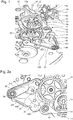
- la
figure 1 est une vue en perspective du mécanisme de mise à l'heure de l'invention lorsque le dispositif de blocage est dans une configuration verrouillée selon une forme de réalisation avantageuse; - la
figure 2a est une vue de dessus de lafigure 1 ; - la
figure 2b est une vue de dessus du mécanisme de mise à l'heure lorsque le dispositif de blocage est dans une configuration déverrouillée ; et - la
figure 3 est une vue détaillée des bras de blocage en prise avec la roue de blocage de lafigure 2a . - Faisant référence à la
figure 1 , le mécanisme de mise à l'heure comporte, de manière conventionnelle, une tirette 12 comprenant un tenon 12a logé dans une creusure de la tige de remontoir 10, une bascule 14 agencée pour coopérer avec la tirette 12, et un pignon coulant 16. Celui-ci est ajusté sur un segment 17a de section transversale carrée d'une tige secondaire 17 de manière à pouvoir se déplacer le long de ce segment 17a d'une première positon axiale, dans laquelle le pignon coulant 16 est un prise avec un pignon de remontoir 18, à une second position axiale, dans laquelle le pignon coulant 16 est en prise avec un renvoi 19 du rouage de mise à l'heure comme illustré à lafigure 2b . - La bascule 14 comporte une extrémité 14a agencée dans une gorge circulaire 16a du pignon coulant 16. Lorsque la tige de remontoir 10 est tirée pour se positionner dans la position axiale correspondant à la position de mise à l'heure, la tirette 12 pivote et repousse la bascule 14 qui fait glisser le pignon coulant 16 le long du segment 17a de la tige secondaire 17. Le pignon coulant 16 se dégage ainsi du pignon du remontoir 18 pour venir engrener avec le renvoi 19 du rouage de mise à l'heure pour la commande des aiguilles.
- Le mécanisme de mise à l'heure selon l'invention comporte en outre un dispositif de blocage de rouage de mise à l'heure. Ce dispositif comporte une roue de blocage 20 configurée pour coopérer d'une part avec le rouage de mise à l'heure et d'autre part avec un premier et second bras de blocage 22, 30. En référence en particulier à la
figure 3 , la roue de blocage 20 comporte une denture dont le sommet de chaque dent présente un profil incurvé. Ce profil particulier de la denture de la roue de blocage 20 permet, d'une part, de conserver une denture permettant l'engrènement avec le pignon coulant 16 via les renvois pour la mise à l'heure, afin de remplir la fonction d'une roue de minuterie standard, et d'autre part, d'augmenter la précision angulaire du blocage par le premier et second bras de blocage 22, 30. A cet effet, comme illustré à lafigure 3 , ces derniers comportent chacun une portion 28, 32 présentant un bord incurvé s'étendant selon un arc de cercle d'un angle compris de préférence entre 30° et 40°, dont le rayon de courbure correspond essentiellement au rayon du cercle de tête de la roue de blocage 20. Les bords incurvés des bras de blocage 22, 30 sont pourvus d'une micro denture afin d'augmenter les points de contact avec la denture de la roue de blocage 20 lorsque les bords incurvés sont en contact avec cette dernière. Ceci a l'avantage d'augmenter la précision angulaire du blocage. - Les premier et second bras de blocage 22, 30 sont par ailleurs superposés et montés pivotant l'un par rapport à l'autre autour d'un tenon 36. Les micro dentures du bras de blocage supérieur 22 et du bras de blocage inférieur 30 sont maintenues contre une portion supérieure, respectivement inférieure de la denture de la roue de blocage 20 par un ressort (220 et 300), lorsque le dispositif de blocage est dans une configuration verrouillée. Ces deux micro dentures présentent une symétrie par rapport à un axe passant par le centre de la roue de blocage 20 et par l'axe de pivotement des deux bras de blocages 22, 30. Les deux micro dentures sont donc orientées dans un sens opposé.
- Il existe donc un arc-boutement entre la denture de la roue de blocage 20 et la micro denture du premier, respectivement du second bras de blocage 22 lorsque la roue tend à vouloir pivoter respectivement dans le sens horaire et antihoraire. Les deux bras de blocage 22, 30 sont donc nécessaires pour empêcher toute rotation de la roue de blocage dans un sens comme dans l'autre. Cela permet de garantir le blocage du rouage de mise à l'heure en cas de chocs importants sur la montre contre lesquels un système de friction classique ne peut résister. Il convient de noter que, contrairement aux mécanismes de mise à l'heure classiques, la chaussée a l'avantage de pouvoir être simplement ajustée sur le canon de la roue des minutes sans aucun « frottement gras », ce qui permet de pallier les problèmes d'usure du rouage de mise à l'heure ou les risques d'endommager le rouage de finissage lorsque le « frottement gras » n'est pas optimal.
- En référence aux
figures 2a et3 , le premier bras de blocage 22 comporte un bec 26 pourvu d'un flan rectiligne 24 s'entendant de la pointe du bec 26 à un coin 25 formant un angle obtus. Le second bras de blocage 30 comporte, quant à lui, une goupille 34 s'étendant verticalement par rapport au plan dans lequel le second bras est agencé pour pivoter - Le dispositif de blocage du rouage de mise à l'heure comporte en outre une bascule de verrouillage/déverrouillage 40 destinée à verrouiller et déverrouiller la roue de blocage 20. A cet effet, cette bascule de verrouillage/déverrouillage 40 est agencée pour pivoter autour d'un tenon 46 et comporte deux bras 42, 44 s'étendant de part et d'autre du tenon 46. Une extrémité d'un des deux bras 42 est logée dans la gorge circulaire 16a du pignon coulant 16 en regard de l'extrémité 14a de la bascule 14. En d'autres termes, l'extrémité du bras 42 de la bascule de verrouillage/déverrouillage 40 et l'extrémité 14a de la bascule 14 sont agencées de part et d'autre d'une tige reliant la partie de pignon coulant 16 destinée à engrener avec le renvoi 19 et la partie du pignon coulant 16 destinée à engrener avec le pignon de remontage 18.
- L'autre des deux bras 44 de la bascule de verrouillage/déverrouillage 40 s'apparente à un bras coudé comportant une portion distale 44a et une portion proximale 44b (
figure 2a ). La portion distale 44a comporte une extrémité pointue logée dans le coin 45 du premier bras de blocage 22 lorsque le dispositif de blocage du rouage de mise à l'heure est dans une configuration verrouillée. La portion proximale 44b est destinée à venir en butée contre la goupille 34 du second bras de blocage 30 lorsque la tige de remontoir 10 est amenée dans une position de mise à l'heure. - Selon la
figure 2a , le dispositif de blocage du rouage de mise à l'heure est dans une configuration verrouillée, c'est-à-dire que la roue de blocage 20 est verrouillée par le premier et second bras de blocage 22, 30 garantissant ainsi le blocage du rouage de mise à l'heure en cas de gros chocs sur la montre et ceci au cours de la marche normale de la montre. - Lorsqu'il est nécessaire d'effectuer une mise à l'heure, la tige de remontoir 10 est amenée d'une première position axiale correspondant à une position de marche de la montre à une seconde position axiale correspondant à une position de mise à l'heure de la montre. Le déplacement axial de la tige de remontoir 10 actionne la tirette 12 en rotation, laquelle va actionner à son tour la bascule 14 afin que son extrémité 14a déplace le pignon coulant 16 le long du segment 17a de la tige secondaire 17 d'une première position axiale, dans laquelle il est en prise avec le pignon de remontoir 18 à une seconde position axiale, dans laquelle il est en prise avec le renvoi 19 du train de rouage de mise à l'heure.
- Au cours de cette séquence, les bras 42, 44 de la bascule de verrouillage/déverrouillage 40 pivotent autour du tenon 46 dans le sens antihoraire sous l'action du pignon coulant 16 sur l'extrémité du bras 42 lorsqu'il se déplace de sa première position à sa seconde position axiale. Au cours de cette séquence, l'extrémité pointue de la portion distale 44a du bras 44 va exercer une contrainte sur le flanc rectiligne 24 du premier bras de blocage 22, tout en se déplaçant le long de ce flanc 24 afin que le premier bras 22 pivote autour du tenon 36 de manière à dégager la première micro denture de la roue de blocage 20. Simultanément, la portion proximale 44b vient en appui contre la goupille 34 du second bras de blocage 30 afin de dégager la seconde micro-denture de la roue de blocage 20.
- Le dispositif de blocage tel qu'illustré à la
figure 2b est dans une configuration déverrouillée et la mise à l'heure a l'avantage de pouvoir se faire sans risque d'endommager le rouage de finissage puisque, comme évoqué précédemment, la chaussée est simplement ajustée sur le canon de la roue des minutes sans aucun « frottement gras ». - Une fois la mise à l'heure effectuée, la tige de remontoir 10 est ramenée dans la première position axiale, et la bascule de verrouillage/déverrouillage 40 pivote autour de son tenon 46 dans le sens horaire, ce qui ramène le bras 44 dans la position illustrée à la
figure 2a . Au même instant, les premier et second bras de couplage 22, 30 pivotent autour du tenon 36 sous l'action de leur ressort de rappel respectif afin de ramener et de maintenir leur micro denture respective contre la denture de la roue de blocage 20 verrouillant ainsi le dispositif de blocage de manière à ce que la montre soit insensible à d'éventuels chocs importants. - Naturellement, l'invention n'est pas limitée à la forme de réalisation qui vient d'être décrite en référence aux figures et des variantes pourraient être envisagées sans sortir du cadre de l'invention. Par exemple, la roue de blocage 20 pourrait remplir uniquement la fonction de blocage du rouage de mise à l'heure sans remplir la fonction de la roue de minuterie. On pourrait donc avoir une roue de blocage montée solidaire de l'axe d'une roue de minuterie standard, et bloquée par les deux bras de blocage. La denture de la roue de blocage sera alors uniquement dédiée à coopérer avec les dentures des bras de blocage et le nombre de dents pourra être augmenté pour améliorer la précision angulaire du blocage. Par ailleurs, selon la forme de réalisation décrite, le pignon coulant est ajusté pour se déplacer sur un segment d'une tige secondaire désaxée par rapport à la tige de remontoir. Or, cette construction est dictée par les contraintes d'un mouvement horloger particulier. On pourrait donc avoir un mécanisme de mise à l'heure selon l'invention dans lequel le segment 17a fait partie intégrante de la tige de remontoir.
Claims (10)
- Mécanisme de mise à l'heure pour mouvement horloger, comportant :un rouage de mise à l'heure,une tige de remontoir (10) agencée pour être déplacée d'une première position axiale dite position de marche à une seconde position axiale dite position de mise à l'heure,un pignon coulant (16) agencé pour être déplacé d'une première position axiale dans laquelle le pignon coulant est dégagé du rouage de mise à l'heure à une seconde position axiale dans laquelle le pignon coulant engrène avec le rouage de mise à l'heure,une bascule (14) en prise avec le pignon coulant (16) et agencée pour pivoter, lorsque la tige de remontoir (10) est amenée d'une position de marche à une position de mise à l'heure et inversement,afin d'amener le pignon coulant de la première à la seconde position axiale et inversement, etun dispositif de blocage du rouage de mise à l'heure,caractérisé en ce que le dispositif de blocage comporte un premier et second bras de blocage (22, 30) et une roue de blocage (20) en prise avec le rouage de mise à l'heure, les premier et second bras de blocage étant agencés, d'une part, pour être en prise avec la roue de blocage (20) dans une configuration dite verrouillée dans laquelle le rouage de mise à l'heure est bloqué et, d'autre part, pour être dégagés de la roue de blocage (20) dans une configuration dite déverrouillée dans laquelle le pignon coulant (16) est libre d'engrener avec le rouage de mise à l'heure, le dispositif de blocage comportant à cet effet une bascule de verrouillage/déverrouillage (40) en prise avec le pignon coulant (16) et agencée pour coopérer avec les premier et second bras de blocage (22, 30) afin d'effectuer un passage de la configuration verrouillée à la configuration déverrouillée et inversement lorsque la tige de remontoir (10) est amenée d'une position de marche à une position de mise à l'heure et inversement.
- Mécanisme selon la revendication 1, caractérisé en ce que la roue de blocage (20) comporte une denture dont le sommet de chaque dent présente un profil incurvé et en ce que les premier et second bras de blocage (22, 30) comportent chacun une portion (28, 32) présentant un bord incurvé pourvu d'une micro denture, le rayon de courbure du bord incurvé correspondant essentiellement au rayon du cercle de tête de la roue de blocage (20).
- Mécanisme selon la revendication 2, caractérisé en ce que les micro dentures des premier et second bras de blocage (22, 30) sont agencées contre la denture de la roue de blocage (20), dans la configuration verrouillée, et sont symétriques l'une par rapport à l'autre de manière à empêcher toute rotation de la roue de blocage dans les deux sens.
- Mécanisme selon l'une des revendications précédentes, caractérisé en ce que les premier et second bras de blocage (22, 30) sont superposés et montés pivotants l'un par rapport à l'autre autour d'un axe commun (36), le bord incurvé du bras de blocage inférieur (30), respectivement supérieur (22), étant destiné à venir au contact d'une portion inférieure, respectivement supérieure, de la denture de la roue de blocage (20).
- Mécanisme selon l'une des revendications précédentes, caractérisé en ce que la bascule de verrouillage/déverrouillage (40) est agencée pour pivoter autour d'un pivot (46) lorsque la tige de remontoir (10) est amenée d'une position de marche à une position de mise à l'heure et inversement, et comporte deux bras (42, 44) s'étendant de part et d'autre du pivot, une extrémité d'un des deux bras étant en prise avec le pignon coulant (16) alors que l'autre des deux bras (42, 44) comporte une portion distale (44a) destinée à coopérer avec le bras de blocage supérieur (22) et une portion proximale destinée à coopérer avec le bras de blocage inférieur (30).
- Mécanisme selon la revendication 5, caractérisé en ce que la portion distale (44a) est en appui contre un flanc rectiligne (24) du bras de blocage supérieur (30) et en ce que la portion proximale (44b) est en appui ou est destinée à venir en appui contre un élément d'actionnement, de préférence une goupille (34), du bras de blocage inférieur (30) afin de dégager les bras de blocage (22, 30) de la denture de la roue de blocage (20) lorsque la bascule de verrouillage/déverrouillage (40) pivote sous l'effet du déplacement axial du pignon coulant (16).
- Mécanisme selon l'une des revendications précédentes, caractérisé en ce que la roue de blocage (20) est la roue de minuterie du rouage de mise à l'heure.
- Mécanisme selon l'une des revendications 1 à 6, caractérisé en ce que la roue de blocage est montée solidaire à l'axe d'une roue de minuterie standard du rouage de mise à l'heure.
- Mouvement horloger comportant le mécanisme selon l'une des revendications précédentes.
- Pièce d'horlogerie comportant le mouvement horloger selon la revendication 9.
Priority Applications (4)
| Application Number | Priority Date | Filing Date | Title |
|---|---|---|---|
| EP17193963.0A EP3462251B1 (fr) | 2017-09-29 | 2017-09-29 | Mécanisme de mise à l'heure pour mouvement horloger |
| US16/104,180 US10955799B2 (en) | 2017-09-29 | 2018-08-17 | Setting mechanism for timepiece movement |
| JP2018173313A JP6547048B2 (ja) | 2017-09-29 | 2018-09-18 | 計時器用ムーブメントのためのセッティング機構 |
| CN201811139626.5A CN109581852B (zh) | 2017-09-29 | 2018-09-28 | 用于钟表机芯的拨针机构 |
Applications Claiming Priority (1)
| Application Number | Priority Date | Filing Date | Title |
|---|---|---|---|
| EP17193963.0A EP3462251B1 (fr) | 2017-09-29 | 2017-09-29 | Mécanisme de mise à l'heure pour mouvement horloger |
Publications (2)
| Publication Number | Publication Date |
|---|---|
| EP3462251A1 true EP3462251A1 (fr) | 2019-04-03 |
| EP3462251B1 EP3462251B1 (fr) | 2020-06-10 |
Family
ID=59997218
Family Applications (1)
| Application Number | Title | Priority Date | Filing Date |
|---|---|---|---|
| EP17193963.0A Active EP3462251B1 (fr) | 2017-09-29 | 2017-09-29 | Mécanisme de mise à l'heure pour mouvement horloger |
Country Status (4)
| Country | Link |
|---|---|
| US (1) | US10955799B2 (fr) |
| EP (1) | EP3462251B1 (fr) |
| JP (1) | JP6547048B2 (fr) |
| CN (1) | CN109581852B (fr) |
Cited By (1)
| Publication number | Priority date | Publication date | Assignee | Title |
|---|---|---|---|---|
| EP4538804A1 (fr) * | 2023-10-10 | 2025-04-16 | Montres Breguet S.A. | Composant d'un mouvement horloger comportant une articulation apte à être verrouillée |
Families Citing this family (2)
| Publication number | Priority date | Publication date | Assignee | Title |
|---|---|---|---|---|
| CN113653799B (zh) * | 2021-09-01 | 2022-08-12 | 西安轻工业钟表研究所有限公司 | 一种可自保险的解锁机构 |
| CN114488756B (zh) * | 2022-03-03 | 2025-06-20 | 天津精诚拓飞科技有限公司 | 一种机芯倒拨针脱开机构 |
Citations (7)
| Publication number | Priority date | Publication date | Assignee | Title |
|---|---|---|---|---|
| CH237215A (fr) * | 1943-12-20 | 1945-04-15 | Sa A Schild | Mouvement de montre à remontoir. |
| JPS4962457U (fr) * | 1972-09-13 | 1974-05-31 | ||
| GB2071364A (en) * | 1980-02-12 | 1981-09-16 | Citizen Watch Co Ltd | Correction system for electronic timepiece with both analog and digital displays |
| JPH02683U (fr) * | 1988-06-10 | 1990-01-05 | ||
| EP1367462A1 (fr) * | 2002-05-28 | 2003-12-03 | Ulysse Nardin S.A. | Echappement pour garde-temps |
| WO2007115984A2 (fr) * | 2006-04-07 | 2007-10-18 | Frederic Piguet S.A. | Piece d'horlogerie comprenant un mecanisme a deux fuseaux horaires |
| CH704331A1 (fr) * | 2011-01-13 | 2012-07-13 | Greubel Forsey S A | Pièce d'horlogerie. |
Family Cites Families (12)
| Publication number | Priority date | Publication date | Assignee | Title |
|---|---|---|---|---|
| CH640686B (fr) * | 1980-10-23 | Ebauchesfabrik Eta Ag | Dispositif de commande coulissant pour montre. | |
| FR2750513B1 (fr) * | 1996-06-26 | 1998-08-07 | Ebauchesfabrik Eta Ag | Piece d'horlogerie avec mecanisme de mise a l'heure par action directe de la tirette |
| CN2610371Y (zh) * | 2003-03-31 | 2004-04-07 | 陈毅力 | 一种钟表拨针机构 |
| DE602006001298D1 (de) * | 2006-05-31 | 2008-07-03 | Montres Breguet Sa | Uhr, die eine verbesserte Vorrichtung zur Zeiteinstellung umfasst |
| DE602007003075D1 (de) * | 2007-04-18 | 2009-12-17 | Eta Sa Mft Horlogere Suisse | Ankerhemmung, die zwei Hemmungszahnräder umfasst |
| DE602007003445D1 (de) * | 2007-04-18 | 2010-01-07 | Eta Sa Mft Horlogere Suisse | Hemmung, die zwei Hemmungsräder umfasst |
| CN102262390B (zh) * | 2010-05-28 | 2012-11-21 | 天津海鸥表业集团有限公司 | 一种手表上条拨针转换机构 |
| EP2487546B1 (fr) * | 2011-02-11 | 2021-06-30 | Montres Journe S.A. | Echappement bi-axial à haute performance, soit EBHP |
| EP2565728B1 (fr) * | 2011-08-29 | 2018-05-09 | ETA SA Manufacture Horlogère Suisse | Mécanisme autonome de commande pour pièce d'horlogerie |
| CN103048911B (zh) * | 2011-10-13 | 2014-12-17 | 天津海鸥表业集团有限公司 | 一种机械钟表的上条与拨针机构 |
| JP5961753B2 (ja) * | 2012-06-07 | 2016-08-02 | デトラ ソシエテ アノニム | 時計用脱進装置 |
| CN202995270U (zh) * | 2012-12-12 | 2013-06-12 | 天王电子(深圳)有限公司 | 一种机械手表及机械手表的上条拨针机构 |
-
2017
- 2017-09-29 EP EP17193963.0A patent/EP3462251B1/fr active Active
-
2018
- 2018-08-17 US US16/104,180 patent/US10955799B2/en active Active
- 2018-09-18 JP JP2018173313A patent/JP6547048B2/ja active Active
- 2018-09-28 CN CN201811139626.5A patent/CN109581852B/zh active Active
Patent Citations (7)
| Publication number | Priority date | Publication date | Assignee | Title |
|---|---|---|---|---|
| CH237215A (fr) * | 1943-12-20 | 1945-04-15 | Sa A Schild | Mouvement de montre à remontoir. |
| JPS4962457U (fr) * | 1972-09-13 | 1974-05-31 | ||
| GB2071364A (en) * | 1980-02-12 | 1981-09-16 | Citizen Watch Co Ltd | Correction system for electronic timepiece with both analog and digital displays |
| JPH02683U (fr) * | 1988-06-10 | 1990-01-05 | ||
| EP1367462A1 (fr) * | 2002-05-28 | 2003-12-03 | Ulysse Nardin S.A. | Echappement pour garde-temps |
| WO2007115984A2 (fr) * | 2006-04-07 | 2007-10-18 | Frederic Piguet S.A. | Piece d'horlogerie comprenant un mecanisme a deux fuseaux horaires |
| CH704331A1 (fr) * | 2011-01-13 | 2012-07-13 | Greubel Forsey S A | Pièce d'horlogerie. |
Cited By (1)
| Publication number | Priority date | Publication date | Assignee | Title |
|---|---|---|---|---|
| EP4538804A1 (fr) * | 2023-10-10 | 2025-04-16 | Montres Breguet S.A. | Composant d'un mouvement horloger comportant une articulation apte à être verrouillée |
Also Published As
| Publication number | Publication date |
|---|---|
| JP6547048B2 (ja) | 2019-07-17 |
| JP2019066469A (ja) | 2019-04-25 |
| US20190101867A1 (en) | 2019-04-04 |
| CN109581852B (zh) | 2020-12-11 |
| CN109581852A (zh) | 2019-04-05 |
| EP3462251B1 (fr) | 2020-06-10 |
| US10955799B2 (en) | 2021-03-23 |
Similar Documents
| Publication | Publication Date | Title |
|---|---|---|
| EP1983389B1 (fr) | Echappement comportant deux roues d'échappement | |
| EP3059643B1 (fr) | Mécanisme de chronographe | |
| EP1152303B1 (fr) | Montre à mécanisme de remontage et de correction d'au moins deux organes indicateurs | |
| EP3483663B1 (fr) | Dispositif d'entraînement pour système de calendrier horloger | |
| EP3462251B1 (fr) | Mécanisme de mise à l'heure pour mouvement horloger | |
| EP2503412B1 (fr) | Mouvement horloger comportant un dispositif à équation du temps marchante | |
| EP3070537A1 (fr) | Base de temps comportant un echappement a impulsion directe et a force constante | |
| EP3059642B1 (fr) | Mécanisme de chronographe | |
| EP3430481A1 (fr) | Mouvement de montre comportant un affichage rétrograde et un anneau des heures sautant | |
| EP3489766B1 (fr) | Mécanisme de correction d'une fonction d'un mouvement d'une pièce d'horlogerie | |
| EP3955066B1 (fr) | Montre comportant un mecanisme de commande a tige et tirette | |
| CH714199A2 (fr) | Mécanisme de mise à l'heure pour mouvement horloger. | |
| EP2884345B1 (fr) | Sautoir pour mouvement d'horlogerie | |
| EP1801671A1 (fr) | Montre à calendrier pourvu de moyens de blocage | |
| EP3206088A1 (fr) | Mécanisme d'échappement | |
| EP4053639B1 (fr) | Dispositif de sélection de fonctions horlogères | |
| EP2241945B1 (fr) | Mécanisme de chronographe et pièce d'horlogerie munie d'un tel mécanisme | |
| EP2339414B1 (fr) | Chronographe mono-poussoir | |
| EP3408712B1 (fr) | Mécanisme de quantième | |
| EP0871095B1 (fr) | Dispositif d'affichage à seconde foudroyante | |
| EP4053640B1 (fr) | Dispositif de selection de fonctions horlogeres | |
| EP3786724A1 (fr) | Mecanisme antichoc et/ou anti-double saut pour mouvement de piece d'horlogerie | |
| EP4312088B1 (fr) | Dispositif à doigt escamotable pour l'actionnement d'un mécanisme horloger | |
| EP4325303A1 (fr) | Mécanisme de quantième perpétuel à cames concentriques | |
| EP3800512B1 (fr) | Dispositif d'affichage à la demande pour pièce d'horlogerie |
Legal Events
| Date | Code | Title | Description |
|---|---|---|---|
| PUAI | Public reference made under article 153(3) epc to a published international application that has entered the european phase |
Free format text: ORIGINAL CODE: 0009012 |
|
| STAA | Information on the status of an ep patent application or granted ep patent |
Free format text: STATUS: THE APPLICATION HAS BEEN PUBLISHED |
|
| AK | Designated contracting states |
Kind code of ref document: A1 Designated state(s): AL AT BE BG CH CY CZ DE DK EE ES FI FR GB GR HR HU IE IS IT LI LT LU LV MC MK MT NL NO PL PT RO RS SE SI SK SM TR |
|
| AX | Request for extension of the european patent |
Extension state: BA ME |
|
| STAA | Information on the status of an ep patent application or granted ep patent |
Free format text: STATUS: REQUEST FOR EXAMINATION WAS MADE |
|
| 17P | Request for examination filed |
Effective date: 20191004 |
|
| RBV | Designated contracting states (corrected) |
Designated state(s): AL AT BE BG CH CY CZ DE DK EE ES FI FR GB GR HR HU IE IS IT LI LT LU LV MC MK MT NL NO PL PT RO RS SE SI SK SM TR |
|
| GRAP | Despatch of communication of intention to grant a patent |
Free format text: ORIGINAL CODE: EPIDOSNIGR1 |
|
| STAA | Information on the status of an ep patent application or granted ep patent |
Free format text: STATUS: GRANT OF PATENT IS INTENDED |
|
| INTG | Intention to grant announced |
Effective date: 20200114 |
|
| GRAS | Grant fee paid |
Free format text: ORIGINAL CODE: EPIDOSNIGR3 |
|
| GRAA | (expected) grant |
Free format text: ORIGINAL CODE: 0009210 |
|
| STAA | Information on the status of an ep patent application or granted ep patent |
Free format text: STATUS: THE PATENT HAS BEEN GRANTED |
|
| AK | Designated contracting states |
Kind code of ref document: B1 Designated state(s): AL AT BE BG CH CY CZ DE DK EE ES FI FR GB GR HR HU IE IS IT LI LT LU LV MC MK MT NL NO PL PT RO RS SE SI SK SM TR |
|
| REG | Reference to a national code |
Ref country code: GB Ref legal event code: FG4D Free format text: NOT ENGLISH |
|
| REG | Reference to a national code |
Ref country code: CH Ref legal event code: EP Ref country code: AT Ref legal event code: REF Ref document number: 1279677 Country of ref document: AT Kind code of ref document: T Effective date: 20200615 |
|
| REG | Reference to a national code |
Ref country code: DE Ref legal event code: R096 Ref document number: 602017017913 Country of ref document: DE |
|
| REG | Reference to a national code |
Ref country code: IE Ref legal event code: FG4D Free format text: LANGUAGE OF EP DOCUMENT: FRENCH |
|
| REG | Reference to a national code |
Ref country code: CH Ref legal event code: NV Representative=s name: ICB INGENIEURS CONSEILS EN BREVETS SA, CH |
|
| REG | Reference to a national code |
Ref country code: LT Ref legal event code: MG4D |
|
| PG25 | Lapsed in a contracting state [announced via postgrant information from national office to epo] |
Ref country code: LT Free format text: LAPSE BECAUSE OF FAILURE TO SUBMIT A TRANSLATION OF THE DESCRIPTION OR TO PAY THE FEE WITHIN THE PRESCRIBED TIME-LIMIT Effective date: 20200610 Ref country code: GR Free format text: LAPSE BECAUSE OF FAILURE TO SUBMIT A TRANSLATION OF THE DESCRIPTION OR TO PAY THE FEE WITHIN THE PRESCRIBED TIME-LIMIT Effective date: 20200911 Ref country code: NO Free format text: LAPSE BECAUSE OF FAILURE TO SUBMIT A TRANSLATION OF THE DESCRIPTION OR TO PAY THE FEE WITHIN THE PRESCRIBED TIME-LIMIT Effective date: 20200910 Ref country code: FI Free format text: LAPSE BECAUSE OF FAILURE TO SUBMIT A TRANSLATION OF THE DESCRIPTION OR TO PAY THE FEE WITHIN THE PRESCRIBED TIME-LIMIT Effective date: 20200610 Ref country code: SE Free format text: LAPSE BECAUSE OF FAILURE TO SUBMIT A TRANSLATION OF THE DESCRIPTION OR TO PAY THE FEE WITHIN THE PRESCRIBED TIME-LIMIT Effective date: 20200610 |
|
| REG | Reference to a national code |
Ref country code: NL Ref legal event code: MP Effective date: 20200610 |
|
| PG25 | Lapsed in a contracting state [announced via postgrant information from national office to epo] |
Ref country code: BG Free format text: LAPSE BECAUSE OF FAILURE TO SUBMIT A TRANSLATION OF THE DESCRIPTION OR TO PAY THE FEE WITHIN THE PRESCRIBED TIME-LIMIT Effective date: 20200910 Ref country code: LV Free format text: LAPSE BECAUSE OF FAILURE TO SUBMIT A TRANSLATION OF THE DESCRIPTION OR TO PAY THE FEE WITHIN THE PRESCRIBED TIME-LIMIT Effective date: 20200610 Ref country code: HR Free format text: LAPSE BECAUSE OF FAILURE TO SUBMIT A TRANSLATION OF THE DESCRIPTION OR TO PAY THE FEE WITHIN THE PRESCRIBED TIME-LIMIT Effective date: 20200610 Ref country code: RS Free format text: LAPSE BECAUSE OF FAILURE TO SUBMIT A TRANSLATION OF THE DESCRIPTION OR TO PAY THE FEE WITHIN THE PRESCRIBED TIME-LIMIT Effective date: 20200610 |
|
| REG | Reference to a national code |
Ref country code: AT Ref legal event code: MK05 Ref document number: 1279677 Country of ref document: AT Kind code of ref document: T Effective date: 20200610 |
|
| PG25 | Lapsed in a contracting state [announced via postgrant information from national office to epo] |
Ref country code: AL Free format text: LAPSE BECAUSE OF FAILURE TO SUBMIT A TRANSLATION OF THE DESCRIPTION OR TO PAY THE FEE WITHIN THE PRESCRIBED TIME-LIMIT Effective date: 20200610 Ref country code: NL Free format text: LAPSE BECAUSE OF FAILURE TO SUBMIT A TRANSLATION OF THE DESCRIPTION OR TO PAY THE FEE WITHIN THE PRESCRIBED TIME-LIMIT Effective date: 20200610 |
|
| PG25 | Lapsed in a contracting state [announced via postgrant information from national office to epo] |
Ref country code: EE Free format text: LAPSE BECAUSE OF FAILURE TO SUBMIT A TRANSLATION OF THE DESCRIPTION OR TO PAY THE FEE WITHIN THE PRESCRIBED TIME-LIMIT Effective date: 20200610 Ref country code: SM Free format text: LAPSE BECAUSE OF FAILURE TO SUBMIT A TRANSLATION OF THE DESCRIPTION OR TO PAY THE FEE WITHIN THE PRESCRIBED TIME-LIMIT Effective date: 20200610 Ref country code: AT Free format text: LAPSE BECAUSE OF FAILURE TO SUBMIT A TRANSLATION OF THE DESCRIPTION OR TO PAY THE FEE WITHIN THE PRESCRIBED TIME-LIMIT Effective date: 20200610 Ref country code: PT Free format text: LAPSE BECAUSE OF FAILURE TO SUBMIT A TRANSLATION OF THE DESCRIPTION OR TO PAY THE FEE WITHIN THE PRESCRIBED TIME-LIMIT Effective date: 20201012 Ref country code: ES Free format text: LAPSE BECAUSE OF FAILURE TO SUBMIT A TRANSLATION OF THE DESCRIPTION OR TO PAY THE FEE WITHIN THE PRESCRIBED TIME-LIMIT Effective date: 20200610 Ref country code: CZ Free format text: LAPSE BECAUSE OF FAILURE TO SUBMIT A TRANSLATION OF THE DESCRIPTION OR TO PAY THE FEE WITHIN THE PRESCRIBED TIME-LIMIT Effective date: 20200610 Ref country code: IT Free format text: LAPSE BECAUSE OF FAILURE TO SUBMIT A TRANSLATION OF THE DESCRIPTION OR TO PAY THE FEE WITHIN THE PRESCRIBED TIME-LIMIT Effective date: 20200610 Ref country code: RO Free format text: LAPSE BECAUSE OF FAILURE TO SUBMIT A TRANSLATION OF THE DESCRIPTION OR TO PAY THE FEE WITHIN THE PRESCRIBED TIME-LIMIT Effective date: 20200610 |
|
| PG25 | Lapsed in a contracting state [announced via postgrant information from national office to epo] |
Ref country code: SK Free format text: LAPSE BECAUSE OF FAILURE TO SUBMIT A TRANSLATION OF THE DESCRIPTION OR TO PAY THE FEE WITHIN THE PRESCRIBED TIME-LIMIT Effective date: 20200610 Ref country code: PL Free format text: LAPSE BECAUSE OF FAILURE TO SUBMIT A TRANSLATION OF THE DESCRIPTION OR TO PAY THE FEE WITHIN THE PRESCRIBED TIME-LIMIT Effective date: 20200610 Ref country code: IS Free format text: LAPSE BECAUSE OF FAILURE TO SUBMIT A TRANSLATION OF THE DESCRIPTION OR TO PAY THE FEE WITHIN THE PRESCRIBED TIME-LIMIT Effective date: 20201010 |
|
| REG | Reference to a national code |
Ref country code: DE Ref legal event code: R097 Ref document number: 602017017913 Country of ref document: DE |
|
| PLBE | No opposition filed within time limit |
Free format text: ORIGINAL CODE: 0009261 |
|
| STAA | Information on the status of an ep patent application or granted ep patent |
Free format text: STATUS: NO OPPOSITION FILED WITHIN TIME LIMIT |
|
| PG25 | Lapsed in a contracting state [announced via postgrant information from national office to epo] |
Ref country code: DK Free format text: LAPSE BECAUSE OF FAILURE TO SUBMIT A TRANSLATION OF THE DESCRIPTION OR TO PAY THE FEE WITHIN THE PRESCRIBED TIME-LIMIT Effective date: 20200610 |
|
| 26N | No opposition filed |
Effective date: 20210311 |
|
| PG25 | Lapsed in a contracting state [announced via postgrant information from national office to epo] |
Ref country code: SI Free format text: LAPSE BECAUSE OF FAILURE TO SUBMIT A TRANSLATION OF THE DESCRIPTION OR TO PAY THE FEE WITHIN THE PRESCRIBED TIME-LIMIT Effective date: 20200610 |
|
| REG | Reference to a national code |
Ref country code: BE Ref legal event code: MM Effective date: 20200930 |
|
| PG25 | Lapsed in a contracting state [announced via postgrant information from national office to epo] |
Ref country code: LU Free format text: LAPSE BECAUSE OF NON-PAYMENT OF DUE FEES Effective date: 20200929 |
|
| PG25 | Lapsed in a contracting state [announced via postgrant information from national office to epo] |
Ref country code: IE Free format text: LAPSE BECAUSE OF NON-PAYMENT OF DUE FEES Effective date: 20200929 Ref country code: BE Free format text: LAPSE BECAUSE OF NON-PAYMENT OF DUE FEES Effective date: 20200930 |
|
| PG25 | Lapsed in a contracting state [announced via postgrant information from national office to epo] |
Ref country code: TR Free format text: LAPSE BECAUSE OF FAILURE TO SUBMIT A TRANSLATION OF THE DESCRIPTION OR TO PAY THE FEE WITHIN THE PRESCRIBED TIME-LIMIT Effective date: 20200610 Ref country code: MT Free format text: LAPSE BECAUSE OF FAILURE TO SUBMIT A TRANSLATION OF THE DESCRIPTION OR TO PAY THE FEE WITHIN THE PRESCRIBED TIME-LIMIT Effective date: 20200610 Ref country code: CY Free format text: LAPSE BECAUSE OF FAILURE TO SUBMIT A TRANSLATION OF THE DESCRIPTION OR TO PAY THE FEE WITHIN THE PRESCRIBED TIME-LIMIT Effective date: 20200610 |
|
| PG25 | Lapsed in a contracting state [announced via postgrant information from national office to epo] |
Ref country code: MK Free format text: LAPSE BECAUSE OF FAILURE TO SUBMIT A TRANSLATION OF THE DESCRIPTION OR TO PAY THE FEE WITHIN THE PRESCRIBED TIME-LIMIT Effective date: 20200610 Ref country code: MC Free format text: LAPSE BECAUSE OF FAILURE TO SUBMIT A TRANSLATION OF THE DESCRIPTION OR TO PAY THE FEE WITHIN THE PRESCRIBED TIME-LIMIT Effective date: 20200610 |
|
| P01 | Opt-out of the competence of the unified patent court (upc) registered |
Effective date: 20230611 |
|
| REG | Reference to a national code |
Ref country code: CH Ref legal event code: U11 Free format text: ST27 STATUS EVENT CODE: U-0-0-U10-U11 (AS PROVIDED BY THE NATIONAL OFFICE) Effective date: 20251001 |
|
| PGFP | Annual fee paid to national office [announced via postgrant information from national office to epo] |
Ref country code: DE Payment date: 20250820 Year of fee payment: 9 |
|
| PGFP | Annual fee paid to national office [announced via postgrant information from national office to epo] |
Ref country code: GB Payment date: 20250827 Year of fee payment: 9 |
|
| PGFP | Annual fee paid to national office [announced via postgrant information from national office to epo] |
Ref country code: FR Payment date: 20250820 Year of fee payment: 9 |
|
| PGFP | Annual fee paid to national office [announced via postgrant information from national office to epo] |
Ref country code: CH Payment date: 20251001 Year of fee payment: 9 |