EP3462039B1 - Electric fan and vacuum cleaner having same - Google Patents
Electric fan and vacuum cleaner having same Download PDFInfo
- Publication number
- EP3462039B1 EP3462039B1 EP17900765.3A EP17900765A EP3462039B1 EP 3462039 B1 EP3462039 B1 EP 3462039B1 EP 17900765 A EP17900765 A EP 17900765A EP 3462039 B1 EP3462039 B1 EP 3462039B1
- Authority
- EP
- European Patent Office
- Prior art keywords
- flow passage
- refluxer
- diffuser
- impeller
- electric fan
- Prior art date
- Legal status (The legal status is an assumption and is not a legal conclusion. Google has not performed a legal analysis and makes no representation as to the accuracy of the status listed.)
- Active
Links
Images


Classifications
-
- F—MECHANICAL ENGINEERING; LIGHTING; HEATING; WEAPONS; BLASTING
- F04—POSITIVE - DISPLACEMENT MACHINES FOR LIQUIDS; PUMPS FOR LIQUIDS OR ELASTIC FLUIDS
- F04D—NON-POSITIVE-DISPLACEMENT PUMPS
- F04D25/00—Pumping installations or systems
- F04D25/02—Units comprising pumps and their driving means
- F04D25/08—Units comprising pumps and their driving means the working fluid being air, e.g. for ventilation
-
- A—HUMAN NECESSITIES
- A47—FURNITURE; DOMESTIC ARTICLES OR APPLIANCES; COFFEE MILLS; SPICE MILLS; SUCTION CLEANERS IN GENERAL
- A47L—DOMESTIC WASHING OR CLEANING; SUCTION CLEANERS IN GENERAL
- A47L5/00—Structural features of suction cleaners
- A47L5/12—Structural features of suction cleaners with power-driven air-pumps or air-compressors, e.g. driven by motor vehicle engine vacuum
- A47L5/22—Structural features of suction cleaners with power-driven air-pumps or air-compressors, e.g. driven by motor vehicle engine vacuum with rotary fans
-
- F—MECHANICAL ENGINEERING; LIGHTING; HEATING; WEAPONS; BLASTING
- F04—POSITIVE - DISPLACEMENT MACHINES FOR LIQUIDS; PUMPS FOR LIQUIDS OR ELASTIC FLUIDS
- F04D—NON-POSITIVE-DISPLACEMENT PUMPS
- F04D29/00—Details, component parts, or accessories
- F04D29/58—Cooling; Heating; Diminishing heat transfer
- F04D29/5806—Cooling the drive system
-
- A—HUMAN NECESSITIES
- A47—FURNITURE; DOMESTIC ARTICLES OR APPLIANCES; COFFEE MILLS; SPICE MILLS; SUCTION CLEANERS IN GENERAL
- A47L—DOMESTIC WASHING OR CLEANING; SUCTION CLEANERS IN GENERAL
- A47L9/00—Details or accessories of suction cleaners, e.g. mechanical means for controlling the suction or for effecting pulsating action; Storing devices specially adapted to suction cleaners or parts thereof; Carrying-vehicles specially adapted for suction cleaners
- A47L9/22—Mountings for motor fan assemblies
-
- A—HUMAN NECESSITIES
- A47—FURNITURE; DOMESTIC ARTICLES OR APPLIANCES; COFFEE MILLS; SPICE MILLS; SUCTION CLEANERS IN GENERAL
- A47L—DOMESTIC WASHING OR CLEANING; SUCTION CLEANERS IN GENERAL
- A47L9/00—Details or accessories of suction cleaners, e.g. mechanical means for controlling the suction or for effecting pulsating action; Storing devices specially adapted to suction cleaners or parts thereof; Carrying-vehicles specially adapted for suction cleaners
- A47L9/28—Installation of the electric equipment, e.g. adaptation or attachment to the suction cleaner; Controlling suction cleaners by electric means
- A47L9/2836—Installation of the electric equipment, e.g. adaptation or attachment to the suction cleaner; Controlling suction cleaners by electric means characterised by the parts which are controlled
- A47L9/2842—Suction motors or blowers
-
- F—MECHANICAL ENGINEERING; LIGHTING; HEATING; WEAPONS; BLASTING
- F04—POSITIVE - DISPLACEMENT MACHINES FOR LIQUIDS; PUMPS FOR LIQUIDS OR ELASTIC FLUIDS
- F04D—NON-POSITIVE-DISPLACEMENT PUMPS
- F04D17/00—Radial-flow pumps, e.g. centrifugal pumps; Helico-centrifugal pumps
- F04D17/08—Centrifugal pumps
- F04D17/16—Centrifugal pumps for displacing without appreciable compression
- F04D17/165—Axial entry and discharge
-
- F—MECHANICAL ENGINEERING; LIGHTING; HEATING; WEAPONS; BLASTING
- F04—POSITIVE - DISPLACEMENT MACHINES FOR LIQUIDS; PUMPS FOR LIQUIDS OR ELASTIC FLUIDS
- F04D—NON-POSITIVE-DISPLACEMENT PUMPS
- F04D25/00—Pumping installations or systems
- F04D25/02—Units comprising pumps and their driving means
- F04D25/08—Units comprising pumps and their driving means the working fluid being air, e.g. for ventilation
- F04D25/082—Units comprising pumps and their driving means the working fluid being air, e.g. for ventilation the unit having provision for cooling the motor
-
- F—MECHANICAL ENGINEERING; LIGHTING; HEATING; WEAPONS; BLASTING
- F04—POSITIVE - DISPLACEMENT MACHINES FOR LIQUIDS; PUMPS FOR LIQUIDS OR ELASTIC FLUIDS
- F04D—NON-POSITIVE-DISPLACEMENT PUMPS
- F04D29/00—Details, component parts, or accessories
- F04D29/18—Rotors
- F04D29/22—Rotors specially for centrifugal pumps
- F04D29/24—Vanes
-
- F—MECHANICAL ENGINEERING; LIGHTING; HEATING; WEAPONS; BLASTING
- F04—POSITIVE - DISPLACEMENT MACHINES FOR LIQUIDS; PUMPS FOR LIQUIDS OR ELASTIC FLUIDS
- F04D—NON-POSITIVE-DISPLACEMENT PUMPS
- F04D29/00—Details, component parts, or accessories
- F04D29/40—Casings; Connections of working fluid
- F04D29/42—Casings; Connections of working fluid for radial or helico-centrifugal pumps
- F04D29/4206—Casings; Connections of working fluid for radial or helico-centrifugal pumps especially adapted for elastic fluid pumps
- F04D29/4226—Fan casings
- F04D29/4253—Fan casings with axial entry and discharge
-
- F—MECHANICAL ENGINEERING; LIGHTING; HEATING; WEAPONS; BLASTING
- F04—POSITIVE - DISPLACEMENT MACHINES FOR LIQUIDS; PUMPS FOR LIQUIDS OR ELASTIC FLUIDS
- F04D—NON-POSITIVE-DISPLACEMENT PUMPS
- F04D29/00—Details, component parts, or accessories
- F04D29/40—Casings; Connections of working fluid
- F04D29/42—Casings; Connections of working fluid for radial or helico-centrifugal pumps
- F04D29/44—Fluid-guiding means, e.g. diffusers
- F04D29/441—Fluid-guiding means, e.g. diffusers especially adapted for elastic fluid pumps
- F04D29/444—Bladed diffusers
-
- F—MECHANICAL ENGINEERING; LIGHTING; HEATING; WEAPONS; BLASTING
- F04—POSITIVE - DISPLACEMENT MACHINES FOR LIQUIDS; PUMPS FOR LIQUIDS OR ELASTIC FLUIDS
- F04D—NON-POSITIVE-DISPLACEMENT PUMPS
- F04D29/00—Details, component parts, or accessories
- F04D29/66—Combating cavitation, whirls, noise, vibration or the like; Balancing
- F04D29/661—Combating cavitation, whirls, noise, vibration or the like; Balancing especially adapted for elastic fluid pumps
- F04D29/667—Combating cavitation, whirls, noise, vibration or the like; Balancing especially adapted for elastic fluid pumps by influencing the flow pattern, e.g. suppression of turbulence
-
- F—MECHANICAL ENGINEERING; LIGHTING; HEATING; WEAPONS; BLASTING
- F05—INDEXING SCHEMES RELATING TO ENGINES OR PUMPS IN VARIOUS SUBCLASSES OF CLASSES F01-F04
- F05D—INDEXING SCHEME FOR ASPECTS RELATING TO NON-POSITIVE-DISPLACEMENT MACHINES OR ENGINES, GAS-TURBINES OR JET-PROPULSION PLANTS
- F05D2250/00—Geometry
- F05D2250/50—Inlet or outlet
- F05D2250/52—Outlet
Definitions
- the present disclosure relates to a field of household appliances, more particularly to an electric fan and a vacuum cleaner having the same.
- the electric fan for the vacuum cleaner is a core functional component of the vacuum cleaner. Therefore, the rational aerodynamic design and structural design of the electric fan can effectively improve the performance of the vacuum cleaner, reduce the energy consumption, and improve the noise level and sound quality of the vacuum cleaner, thereby significantly improving user satisfaction and improving the selling point of vacuum cleaner products.
- the heat dissipation problem of an electric motor is also a technical problem of the electric fan for the vacuum cleaner. The good heat dissipation can solve the temperature rise problem of the electric fan and prolong the service life of the electric fan.
- the airflow velocity at outlet of an impeller of the electric fan is relatively high, and the flow velocity needs to be reduced by diffusing action of the diffuser, so as to reduce the flow losses.
- some electric fans for vacuum cleaners use a vaneless diffuser, because since the vaneless diffuser has insufficient control effect on the airflow, especially in the application scenario of the radial size of the electric fan for the vacuum cleaner and the steering distance of the airflow being relatively small, this is easy to cause the airflow to be turbulent, which reduces the aerodynamic performance of the electric fan.
- Some other vacuum cleaners use a conventional vaned diffuser, which has a relatively large tangential velocity of the airflow at the outlet of the vane of the conventional vaned diffuser. Therefore, the tangential velocity is not utilized and is mostly wasted, and the flow velocity of the airflow is high, and the flow losses in the flow passage of the above conventional vaned diffuser are large, such that the efficiency of the electric fan is low.
- US 2017/051755 A1 concerns vacuum cleaners, and in particular to a fan of a vacuum cleaner and a diffuser for the fan.
- WO 2016/144126 A1 concerns a vacuum suction unit.
- WO 97/19629 A1 concerns a blower for a vacuum cleaner.
- US 6 425 739 B1 concerns in-line fans, and more particularly to redirecting vanes within the housing of in-line fans of the centrifugal impeller type.
- CN 1 108 138 C concerns an electric vacuum cleaner, and more particularly an electric blower for providing the suction force.
- the present disclosure seeks to solve at least one of the problems existing in the related art. To this end, the present disclosure proposes an electric fan, which has high efficiency.
- the present disclosure also proposes a vacuum cleaner having the above-described electric fan.
- the electric fan includes a cover having an open side; an impeller disposed in the cover; a diffuser including a diffuser body and a plurality of vanes, the diffuser body being located at a side of the impeller adjacent to the cover, the plurality of vanes being disposed at an end of the diffuser body adjacent to the impeller and spaced apart from one another along an outer circumference of the impeller, an outlet angle of each vane being denoted as ⁇ , and the ⁇ satisfying: 45° ⁇ 90°; and a refluxer disposed at an end of the diffuser body away from the impeller.
- the vanes of the diffuser at the outer circumference of the impeller and enabling the outlet angle ⁇ of each vane to satisfy 45° ⁇ 90°, a tangential flow velocity of airflow is reduced while ensuring aerodynamic performance of the electric fan, such that flow losses of the airflow are reduced, and the efficiency of the electric fan is improved.
- each vane deviates from a radial direction of the impeller, and each vane protrudes in a direction away from a datum line, and the datum line is a connection line of an end of the vane adjacent to a center of the impeller and the center of the impeller.
- the datum line is a connection line of an end of the vane adjacent to a center of the impeller and the center of the impeller.
- a 1 is a cross-sectional area at an inlet of the diffuser flow passage
- a 2 is a cross-sectional area at an outlet of the diffuser flow passage
- L 1 is a length of the diffuser flow passage.
- a cross-sectional area of the diffuser flow passage linearly increases in a direction from the inlet of the diffuser flow passage to the outlet of the diffuser flow passage;
- the diffuser flow passage includes a first flow passage and a second flow passage sequentially connected in the direction from the inlet of the diffuser flow passage to the outlet of the diffuser flow passage, a cross-sectional area of the first flow passage linearly increases, and an increase rate of a cross-sectional area of the second flow passage is less than an increase rate of the cross-sectional area of the first flow passage.
- a thickness of an end of each vane adjacent to a center of the impeller is less than a thickness of an end of the vane away from the center of the impeller.
- an end of each vane away from a center of the impeller extends out of an outer circumferential wall of the diffuser body.
- the refluxer is disposed at an outer circumference of the diffuser body and is spaced apart from the diffuser body to define a refluxer flow passage.
- the refluxer flow passage has a simple structure and good airtightness, thereby further improving the aerodynamic performance of the electric fan.
- a diffusion degree of the refluxer flow passage is denoted as ⁇ 2
- a cross-sectional area of the refluxer flow passage remains constant in a direction from the inlet of the refluxer flow passage to the outlet of the refluxer flow passage; or the cross-sectional area of the refluxer flow passage uniformly increases in the direction from the inlet of the refluxer flow passage to the outlet of the refluxer flow passage.
- a side of the refluxer away from the impeller is provided with an electric motor, and the outlet of the refluxer flow passage faces the electric motor.
- the refluxer flow passage obliquely extends along an axial direction of the impeller, from the inlet of the refluxer flow passage to the outlet of the refluxer flow passage and in a direction approaching a central axis of the impeller.
- the refluxer flow passage has a simple structure and is easy to implement.
- one of the diffuser body and the refluxer is provided with at least one fitting protrusion, and the other one of the diffuser body and the refluxer defines at least one assembling groove fitted with the fitting protrusion.
- the cover defines a through air inlet, the air inlet is circular, a diameter of the air inlet is denoted as d, and d satisfies: d ⁇ 40mm.
- the vacuum cleaner according to embodiments of a second aspect of the present disclosure includes an electric fan according to the above embodiments of the first aspect of the present disclosure.
- the vacuum cleaner by employing the above electric fan, energy consumption of the vacuum cleaner is reduced, efficiency of the vacuum cleaner is improved, and noise of the vacuum cleaner is reduced, thereby improving sound quality of the vacuum cleaner, and promoting selling points of the vacuum cleaner.
- connection means, for example, fixed connections, detachable connections, or integral connections; may also be mechanical or electrical connections; may also be direct connections or indirect connections via intervening structures; may also be inner communications of two elements.
- the electric fan 100 includes a cover 1, an impeller 2, a diffuser 3 and a refluxer 4.
- the cover 1 has an open side.
- the impeller 2 is disposed in the cover 1.
- the diffuser 3 includes a diffuser body 31 and a plurality of vanes 32.
- the diffuser body 31 is located at a side of the impeller 2 adjacent to the cover 1.
- the plurality of vanes 32 are disposed at an end of the diffuser body 31 adjacent to impeller 2, and the plurality of vanes are spaced apart from one another along an outer circumference of the impeller 2.
- An outlet angle of each vane 32 is denoted as ⁇ , and ⁇ satisfies: 45° ⁇ 90°.
- the refluxer 4 is disposed at an end of the diffuser body 31 away from the impeller 2. It should be noted herein that, the direction “outside” is a direction away from a central axis of the electric fan 100, and an opposite direction thereof is defined as "inside”.
- a rear side of the cover 1 is completely opened, and both the impeller 2 and diffuser 3 are disposed in the cover 1.
- the diffuser body 31 is located at a rear side of the impeller 2, the plurality of vanes are disposed at a front end of the diffuser body 31, and the refluxer 4 is disposed at a rear end of the diffuser body 31.
- each vane 32 of the diffuser 3 satisfies 45° ⁇ 90°, the outlet angle ⁇ of the vane 32 is relatively large, the vane can control flow of airflow to ensure the aerodynamic performance of the electric fan 100, and a tangential velocity component of the airflow diffused by the diffuser 3 is reduced to reduce the flow velocity of the airflow, thereby reducing the resistance losses of the airflow, and promoting the performance of the electric fan 100.
- the outlet angle ⁇ of the vane 32 is understood as an included angle between a tangent to a mean camber line of the vane 32 at the outlet along an airflow direction and a circumferential direction, and the “mean camber line” refers to a middle line of a section of the vane 32 along a streamline direction thereof.
- the vane 32 and the impeller 2 may be located in the same cross section of the electric fan 100, in which case the vane 32 and the impeller 2 are radially opposite to each other, as illustrated in Fig. 5 ; certainly, the vane 32 and the impeller 2 may also be located in different cross sections, in which case the vane 32 and the impeller 2 are axially staggered to each other.
- an external air outside the electric fan 100 may enter the cover 1 through an air inlet 10a in a front side of the cover 1, and is rotated with rotation of the impeller 2, such that the air obtains a certain amount of energy; the air is rotated to an outer edge of the impeller 2 and flows to the diffuser 3 under a centrifugal force of inertia during the rotation of the air; the diffuser 3 converts kinetic energy of the air into static pressure energy; and then the refluxer 4 functions to guide and rectify to some extent the air out of the diffuser 3.
- the outlet angle ⁇ of each vane 32 of the diffuser 3 satisfies 45° ⁇ 90°, and the outlet angle ⁇ is relatively large, such that the vane 32 is curved to a radial direction of the diffuser 3 at the outlet of the vane, the tangential velocity component of the airflow diffused by the diffuser 3 is reduced, the flow velocity of the airflow is reduced, and more kinetic energy is converted into static pressure energy, thereby promoting a diffusion coefficient of the diffuser 3 (which may be understood as a ratio of air pressure at the outlet of the diffuser 3 to air pressure at the inlet of the diffuser 3); moreover, energy losses of the air flowing within the diffuser 3 is reduced, and the resistance losses of the airflow is reduced, thereby further improving the efficiency of the electric fan 100 and promoting the performance of the electric fan 100.
- the vanes 32 of the diffuser 3 by disposing the vanes 32 of the diffuser 3 at the outer circumference of the impeller 2 and enabling the outlet angle ⁇ of each vane 32 to satisfy 45° ⁇ 90°, a tangential flow velocity of the airflow is reduced while ensuring aerodynamic performance of the electric fan 100, such that flow losses of the airflow are reduced, the efficiency of the electric fan 100 is improved, and the performance of the electric fan 100 is promoted.
- each vane 32 deviates from a radial direction of the impeller 2, and each vane 32 protrudes in a direction away from a datum line
- the datum line is a connection line of an end of the vane 32 adjacent to a center of the impeller 2 and the center of the impeller 2.
- the datum line is a connection line of an inlet end of the vane 32 (i.e.
- an inlet angle of the vane 32 (an included angle between a tangent to the mean camber line of the vane 32 at the inlet along the airflow direction and the circumferential direction) is smaller than the outlet angle ⁇ of the vane 32, and a vane angle (an included angle between a tangent to the mean camber line of the vane 32 along the airflow direction and the circumferential direction) increases from inside to outside, such that the tangential flow velocity of the airflow decreases gradually, the flow velocity of the airflow is reduced, and the flow losses of the airflow are reduced, thereby promoting the performance of the electric fan 100.
- a diffusion degree of the diffuser flow passage 30 is denoted as ⁇ 1
- ⁇ 1 a diffusion degree of the diffuser flow passage 30
- a 1 is a cross-sectional area at an inlet 30a of the diffuser flow passage
- a 2 is a cross-sectional area at an outlet 30b of the diffuser flow passage
- L 1 is a length of the diffuser flow passage 30.
- the "length of the diffuser flow passage 30" is a length of a central axis of the diffuser flow passage 30.
- a cross-sectional area of the diffuser flow passage 30 linearly increases in a direction from the inlet 30a of the diffuser flow passage to the outlet 30b of the diffuser flow passage;
- the diffuser flow passage 30 includes a first flow passage and a second flow passage (not shown) sequentially connected in the direction from the inlet 30a of the diffuser flow passage to the outlet 30b of the diffuser flow passage, a cross-sectional area of the first flow passage linearly increases, and an increase rate of a cross-sectional area of the second flow passage is less than an increase rate of the cross-sectional area of the first flow passage.
- a cross-sectional area of the diffuser flow passage 30 linearly increases from A 1 to A 2 , in which case the cross-sectional area of the diffuser flow passage 30 is gradually varying; in addition, the cross-sectional area of the first flow passage linearly increases, and the increase rate of the cross-sectional area of the second flow passage is less than the increase rate of the cross-sectional area of the first flow passage, in which case the cross-sectional area of the second flow passage may linearly increase or curvilinearly increase, which is not limited.
- a flow separation phenomenon of the airflow within the diffuser flow passage 30 can be alleviated, such that flow separation losses of the airflow within the diffuser flow passage 30 are reduced, and energy losses of the air flowing within the diffuser 3 are further reduced, thereby promoting the performance of the electric fan 100.
- the cross-sectional area of the first flow passage of the diffuser flow passage 30 to increase linearly, and setting the increase rate of the cross-sectional area of the second flow passage thereof to be less than the increase rate of the cross-sectional area of the first flow passage, the flow separation phenomenon of the airflow within the second flow passage can be further alleviated, thereby further promoting the performance of the electric fan 100.
- a thickness of an end of each vane 32 adjacent to the center of the impeller 2 is less than a thickness of an end thereof away from the center of the impeller 2.
- a thickness of an end thereof away from the center of the impeller 2 is less than a thickness of an end thereof away from the center of the impeller 2.
- the thickness of the inlet end of the vane 32 is less than the thickness of the outlet end of the vane 32, and the thickness of the inlet end of the vane 32 is thinner, such that it is convenient for the airflow to smoothly flow into the diffuser 3 via the inlet end of the vane 32, obstruction of the airflow entering the diffuser 3 is reduced, and energy consumption of the airflow is reduced, thereby broadening the high-efficiency operation range of the electric fan 100, improving capacity of the electric fan 100 adapting work conditions, and promoting applicability of the electric fan 100.
- the "thickness" refers to a length of the vane 32 in a normal direction of the mean camber line thereof.
- the thickness of the vane 32 is optionally increased uniformly from the inlet end of the vane 32 to the outlet end of the vane 32 along the extending direction of the vane 32, such that the cross-sectional area of the diffuser flow passage 30 defined between two adjacent vanes 32 varies uniformly, thereby further reducing the flow separation losses of the airflow.
- each vane 32 away from the center of the impeller 2 extends out of an outer circumferential wall of the diffuser body 31.
- the diffuser body 31 may be a substantially ring-shaped structure, the plurality of vanes 32 are disposed at an outer edge of the diffuser body 31, and the outlet end of each vane 32 extends outwards and beyond the outer circumferential wall of the diffuser body 31, such that the length of the vane 32 is appropriately lengthened, and the control effect on the flow of the airflow by the vane 32 is enhanced.
- the "length” refers to a length of the mean camber line of the vane 32.
- the refluxer 4 is disposed at the outer circumference of the diffuser body 31 and the refluxer 4 is spaced apart from the diffuser body 31 to define a refluxer flow passage 40.
- the refluxer 4 may be a ring-shaped structure, and the refluxer 4 is coaxially disposed outside the diffuser body 31, such that the refluxer flow passage 40 is formed as a substantially ring-shaped structure, which has a simple and compact structure and is easy to implement.
- a spacing between the refluxer 4 and the diffuser body 31 forms the refluxer flow passage 40, such that the refluxer flow passage 40 forms an enclosed flow passage, and presence of a sudden expansion portion of the refluxer flow passage 40 is avoided, thereby further promoting the aerodynamic performance of the electric fan 100.
- ⁇ 2 2 arctan A 4 / ⁇ ⁇ A 3 / ⁇ L 2 ⁇ 14 °
- a 3 is a cross-sectional area at an inlet 40a of the refluxer flow passage
- a 4 is a cross-sectional area at an outlet 40b of the refluxer flow passage
- L 2 is a length of the refluxer flow passage 40.
- a front end of the refluxer 4 and the diffuser body 31 define the inlet 40a of the refluxer flow passage therebetween, while a rear end of the refluxer 4 and the diffuser body 31 define the outlet 40b of the refluxer flow passage therebetween.
- the cross-sectional area of the refluxer flow passage 40 may remain constant in a direction from the inlet 40a of the refluxer flow passage to the outlet 40b of the refluxer flow passage; or the cross-sectional area of the refluxer flow passage 40 may also increase uniformly in the direction from the inlet 40a of the refluxer flow passage to the outlet 40b of the refluxer flow passage. That is to say, A 3 ⁇ A 4 , i.e.
- a 4 A 3
- the cross-sectional area of the refluxer flow passage 40 uniformly increases from A 3 to A 4 (in this case, A 3 ⁇ A 4 ).
- a side of the refluxer 4 away from the impeller 2 is provided with an electric motor 5, and the outlet 40b of the refluxer flow passage faces the electric motor 5.
- the electric motor 5 is disposed at a rear side of the refluxer 4, and the outlet 40b of the refluxer flow passage faces the electric motor 5, such that the airflow out of the refluxer 4 can dissipate heat of the electric motor 5, operation condition of the electric motor 5 is improved, thereby solving temperature rise problem of the electric fan 100 and prolonging service life of the electric fan 100.
- the outlet 40b of the refluxer flow passage is a substantially ring-shaped outlet, such that the heat of the electric motor 5 can be dissipated more evenly.
- the outlet 40b of the refluxer flow passage is disposed outside the electric motor 5, such that relatively large obstruction to the airflow generated by the components within the electric motor 5, such as stator and rotor structure, coil and carbon brush, etc., due to heat dissipation of the electric motor 5 which requires the airflow to flow into an interior of the electric motor 5, can be avoided.
- This obstruction will affect the flow of the airflow within an upstream flow passage such as the refluxer flow passage 40.
- the above arrangement way of the outlet 40b of the refluxer flow passage reduces the flow losses of the airflow, thereby promoting the efficiency of the electric fan 100.
- the refluxer flow passage 40 extends obliquely along an axial direction of the impeller 2, from the inlet 40a of the refluxer flow passage to the outlet 40b of the refluxer flow passage and in a direction approaching a central axis of the impeller 2. That is to say, the refluxer flow passage 40 extends obliquely from the inlet 40a of the refluxer flow passage to the outlet 40b of the refluxer flow passage along the axial direction of the impeller 2 from outside to inside, such that the outlet 40b of the refluxer flow passage faces the electric motor 5 to dissipate the heat of the electric motor 5, and a structure of the refluxer flow passage 40 is further simplified.
- one of the diffuser body 31 and the refluxer 4 is provided with at least one fitting protrusion 311, and the other one of the diffuser body 31 and the refluxer 4 defines at least one assembling groove 41 fitted with the fitting protrusion 311.
- the fitting between the fitting protrusion 311 and the assembling groove 41 disassembly and assembly of the diffuser 3 and the refluxer 4 are facilitated, and the structure of the diffuser 3 and the refluxer 4 after assembly is more compact.
- each fitting protrusion 311 is provided on the outer circumferential wall of the diffuser body 31, and the six fitting protrusions 311 may be distributed at even intervals along a circumferential direction of the diffuser body 31, each fitting protrusion 311 extends rearwards from the outer circumferential wall of the diffuser body 31 along the axial direction of the electric fan 100.
- the refluxer 4 is correspondingly provided with six assembling grooves 41, each assembling groove 41 is formed by recessing a partial edge of the refluxer 4 rearwards along the axial direction of the electric fan 100.
- the six fitting protrusions 311 are fitted in the six assembling grooves 41 in one-to-one correspondence, thereby facilitating the disassembly and assembly between the diffuser 3 and the refluxer 4. It could be understood that, the number of the fitting protrusions 311 and the assembling grooves 41, and their arrangement way can be set according to actual requirements, so as to better satisfy the actual application.
- the cover 1 defines a through air inlet 10a, the air inlet 10a is circular, a diameter of the air inlet 10a is denoted as d, and d satisfies: d ⁇ 40mm.
- the air inlet 10a is defined in the front side of the cover 1.
- air volume of the electric fan 100 can be promoted at the same rotating speed of the impeller 2; or in the case where a certain amount of air volume is required, the rotating speed of the impeller 2 can be reduced, so as to reduce noise of the impeller 2.
- the electric fan 100 according to one specific embodiment of the present disclosure will be described in detail below with reference to Figs. 1 to 8 .
- the electric fan 100 includes the cover 1, the impeller 2, the diffuser 3, the refluxer 4, and the electric motor 5 that are arranged from front to rear.
- the front side of the cover 1 defines a through air inlet 10a, the air inlet 10a is a circular opening, and the diameter d of the air inlet 10a ⁇ 40mm.
- the rear side of the cover 1 is completely open, and the cover 1 and the refluxer 4 can be connected through an interference fit, such that the cover 1 and the refluxer 4 define a cavity therebetween, and the impeller 2 and the diffuser 3 are both disposed in the above cavity.
- the outer circumferential wall of the diffuser body 31 is provided with six fitting protrusions 311 at even intervals along the circumferential direction of the diffuser body 31, and the refluxer 4 is correspondingly provided with six assembling grooves 41, such that the diffuser 3 is connected to the refluxer 4 through the fitting between the fitting protrusions 311 and the assembling grooves 41.
- the electric motor 5 has an electric motor shaft 51.
- the electric motor shaft 51 penetrates the diffuser 3 and the impeller 2 in turn from rear to front, and a front end of the electric motor shaft 51 is provided with a shaft head nut 6, so as to mount the impeller 2 onto the electric motor shaft 51.
- a rear end of the electric motor shaft 51 is provided with a mounting block 52.
- the mounting block 52 is placed in a mounting groove 31a in the rear end of the diffuser 3, and the electric motor 5 is fixedly connected to the diffuser 3 through a connecting member 8.
- the connecting member 8 may optionally be a screw, and so on.
- the impeller 2 and a shaft shoulder of the electric motor shaft 51 may be provided with a washer 7 therebetween.
- the diffuser 3 includes the diffuser body 31 and the plurality of vanes 32.
- the diffuser body 31 may be a substantially ring-shaped structure, the plurality of vanes 32 are disposed at the front end of the diffuser body 31, the plurality of vanes 32 are spaced apart evenly from one another along the outer circumference of the impeller 2, and the plurality of vanes 32 and the impeller 2 are located in the same cross section of the electric fan 100, in which case the vane 32 is radially opposite to the impeller 2.
- Each vane 32 extends from inside to outside, and beyond the outer edge of the diffuser body 31.
- each vane 32 increases from inside to outside, and the outlet angle ⁇ of the vane 32 satisfies 45° ⁇ 90°.
- the thickness of each vane 32 increases uniformly from inside to outside. Meanwhile, the front end of each vane 32 abuts against the inner wall surface of the cover 1, such that two adjacent vanes 32 and the cover 1 collectively define the diffuser flow passage 30 thereamong.
- the refluxer 4 may be ring-shaped structure, and the refluxer 4 is coaxially disposed outside the diffuser body 31 at an interval, such that the refluxer 4 and the diffuser body 31 define the refluxer flow passage 40 therebetween.
- the refluxer flow passage 40 extends obliquely from the inlet 40a of the refluxer flow passage to the outlet 40b of the refluxer flow passage along a front-and-rear direction from outside to inside, such that the outlet 40b of the refluxer flow passage faces the electric motor 5 to dissipate the heat of the electric motor 5.
- the electric motor shaft 51 drives the impeller 2 to rotate at a high speed, the external air enters the impeller 2 through the air inlet 1 0a, and is rotated with rotation of the impeller 2, such that the air obtains a certain amount of energy; the air is rotated to the outer edge of the impeller 2 and flows into the diffuser flow passage 30 under the centrifugal force of inertia during the rotation of the air; the diffuser 3 converts kinetic energy of the air into static pressure energy due to linear increase of the cross-sectional area of the diffuser flow passage 30; and then the refluxer 40 guides and diffuses the air out of the diffuser 3, and the air flows out of the refluxer flow passage 40 and dissipates the heat of the electric motor 5.
- both of the diffuser flow passage 30 and the refluxer flow passage 40 can reduce the flow losses of the airflow, so as to reduce the energy consumption, promote the performance of the electric fan 100, and improve the applicability of the electric fan 100; meanwhile, the airflow can perform good heat dissipation of the electric motor 5, prolonging the service life of the electric fan 100; moreover, the air volume of the electric fan 100 is relatively large at the same rotating speed of the impeller 2, or the noise of the electric fan 100 is relatively low in the case of a certain amount of air volume.
- the vacuum cleaner (not shown) according to embodiments of a second aspect of the present disclosure includes an electric fan 100 according to the above embodiments of the first aspect of the present disclosure.
- a vacuum cleaner defines a suction port and a discharge port
- the electric fan 100 is mounted in the vacuum cleaner
- the suction port of the vacuum cleaner is in communication with the air inlet 10a of the electric fan 100
- the vacuum cleaner is internally provided with a filter device and a dust collecting device.
- the electric fan 100 operates, such that a certain amount of negative pressure is produced at the suction port, the surrounding dust laden air is sucked into the vacuum cleaner through the suction port, and filtered by the filter device, such that the foreign matter such as the dust is filtered and collected in the dust collecting device.
- the clean air then flows into the electric fan 100 through the air inlet 10a, and finally discharged though the discharge port of the vacuum cleaner.
- the vacuum cleaner by employing the above electric fan 100, energy consumption of the vacuum cleaner is reduced, efficiency of the vacuum cleaner is improved, and noise of the vacuum cleaner is reduced, thereby improving sound quality of the vacuum cleaner, and promoting selling points of the vacuum cleaner.
Description
- The present disclosure relates to a field of household appliances, more particularly to an electric fan and a vacuum cleaner having the same.
- Energy efficient and low-noise characteristics of a vacuum cleaner are one of the important trends in its development. The electric fan for the vacuum cleaner is a core functional component of the vacuum cleaner. Therefore, the rational aerodynamic design and structural design of the electric fan can effectively improve the performance of the vacuum cleaner, reduce the energy consumption, and improve the noise level and sound quality of the vacuum cleaner, thereby significantly improving user satisfaction and improving the selling point of vacuum cleaner products. At the same time, the heat dissipation problem of an electric motor is also a technical problem of the electric fan for the vacuum cleaner. The good heat dissipation can solve the temperature rise problem of the electric fan and prolong the service life of the electric fan.
- The airflow velocity at outlet of an impeller of the electric fan is relatively high, and the flow velocity needs to be reduced by diffusing action of the diffuser, so as to reduce the flow losses. In the related art, some electric fans for vacuum cleaners use a vaneless diffuser, because since the vaneless diffuser has insufficient control effect on the airflow, especially in the application scenario of the radial size of the electric fan for the vacuum cleaner and the steering distance of the airflow being relatively small, this is easy to cause the airflow to be turbulent, which reduces the aerodynamic performance of the electric fan. Some other vacuum cleaners use a conventional vaned diffuser, which has a relatively large tangential velocity of the airflow at the outlet of the vane of the conventional vaned diffuser. Therefore, the tangential velocity is not utilized and is mostly wasted, and the flow velocity of the airflow is high, and the flow losses in the flow passage of the above conventional vaned diffuser are large, such that the efficiency of the electric fan is low.
-
US 2017/051755 A1 concerns vacuum cleaners, and in particular to a fan of a vacuum cleaner and a diffuser for the fan. -
WO 2016/144126 A1 concerns a vacuum suction unit. -
WO 97/19629 A1 -
US 6 425 739 B1 concerns in-line fans, and more particularly to redirecting vanes within the housing of in-line fans of the centrifugal impeller type. -
CN 1 108 138 C - Aspects of the invention are defined by the accompanying claims. The embodiments and/or examples of the following description not falling under the scope of the claims should be interpreted as examples useful for understanding the invention. According to a first aspect there is provided an electric fan in accordance with
claim 1. According to a second aspect there is provided a vacuum cleaner in accordance with claim 12. - The present disclosure seeks to solve at least one of the problems existing in the related art. To this end, the present disclosure proposes an electric fan, which has high efficiency.
- The present disclosure also proposes a vacuum cleaner having the above-described electric fan.
- The electric fan according to embodiments of a first aspect of the present disclosure includes a cover having an open side; an impeller disposed in the cover; a diffuser including a diffuser body and a plurality of vanes, the diffuser body being located at a side of the impeller adjacent to the cover, the plurality of vanes being disposed at an end of the diffuser body adjacent to the impeller and spaced apart from one another along an outer circumference of the impeller, an outlet angle of each vane being denoted as β, and the β satisfying: 45°≤β≤90°; and a refluxer disposed at an end of the diffuser body away from the impeller.
- For the electric fan according to embodiments of the present disclosure, by disposing the vanes of the diffuser at the outer circumference of the impeller and enabling the outlet angle β of each vane to satisfy 45°≤β≤90°, a tangential flow velocity of airflow is reduced while ensuring aerodynamic performance of the electric fan, such that flow losses of the airflow are reduced, and the efficiency of the electric fan is improved.
- According to some embodiments of the present disclosure, each vane deviates from a radial direction of the impeller, and each vane protrudes in a direction away from a datum line, and the datum line is a connection line of an end of the vane adjacent to a center of the impeller and the center of the impeller. Thus, a vane angle progressively increases from inside to outside, and the flow losses of the airflow can be reduced, thereby promoting the performance of the electric fan.
- According to some embodiments of the present disclosure, two adjacent vanes define a diffuser flow passage therebetween, a diffusion degree of the diffuser flow passage is denoted as Δ1, and the Δ1 satisfies: Δ1 =
2arctan 
- According to the present invention, a cross-sectional area of the diffuser flow passage linearly increases in a direction from the inlet of the diffuser flow passage to the outlet of the diffuser flow passage; the diffuser flow passage includes a first flow passage and a second flow passage sequentially connected in the direction from the inlet of the diffuser flow passage to the outlet of the diffuser flow passage, a cross-sectional area of the first flow passage linearly increases, and an increase rate of a cross-sectional area of the second flow passage is less than an increase rate of the cross-sectional area of the first flow passage. Thus, flow separation losses of air are reduced, and the performance of the electric fan is improved.
- According to some embodiments of the present disclosure, a thickness of an end of each vane adjacent to a center of the impeller is less than a thickness of an end of the vane away from the center of the impeller. Thus, obstruction of the airflow entering the diffuser is reduced, and high-efficiency operation range of the electric fan is broadened.
- According to some embodiments of the present disclosure, an end of each vane away from a center of the impeller extends out of an outer circumferential wall of the diffuser body. Thus, the control effect of the vane on the flow of the airflow is enhanced.
- According to some embodiments of the present disclosure, the refluxer is disposed at an outer circumference of the diffuser body and is spaced apart from the diffuser body to define a refluxer flow passage. Thus, the refluxer flow passage has a simple structure and good airtightness, thereby further improving the aerodynamic performance of the electric fan.
- According to some embodiments of the present disclosure, a diffusion degree of the refluxer flow passage is denoted as Δ2, and the Δ2 satisfies:

- According to some embodiments of the present disclosure, a cross-sectional area of the refluxer flow passage remains constant in a direction from the inlet of the refluxer flow passage to the outlet of the refluxer flow passage; or the cross-sectional area of the refluxer flow passage uniformly increases in the direction from the inlet of the refluxer flow passage to the outlet of the refluxer flow passage. Thus, flow separation losses of the airflow within the refluxer flow passage are reduced, and the performance of the electric fan is further improved.
- According to some embodiments of the present disclosure, a side of the refluxer away from the impeller is provided with an electric motor, and the outlet of the refluxer flow passage faces the electric motor. Thus, heat dissipation of the electric motor is facilitated, thereby prolonging service life of the electric fan.
- According to some embodiments of the present disclosure, the refluxer flow passage obliquely extends along an axial direction of the impeller, from the inlet of the refluxer flow passage to the outlet of the refluxer flow passage and in a direction approaching a central axis of the impeller. Thus, the refluxer flow passage has a simple structure and is easy to implement.
- According to some embodiments of the present disclosure, one of the diffuser body and the refluxer is provided with at least one fitting protrusion, and the other one of the diffuser body and the refluxer defines at least one assembling groove fitted with the fitting protrusion. Thus, assembly and disassembly of the diffuser and the refluxer are facilitated.
- According to some embodiments of the present disclosure, the cover defines a through air inlet, the air inlet is circular, a diameter of the air inlet is denoted as d, and d satisfies: d≥40mm. Thus, air volume of the electric fan can be promoted, and noise of the impeller can be reduced.
- The vacuum cleaner according to embodiments of a second aspect of the present disclosure includes an electric fan according to the above embodiments of the first aspect of the present disclosure.
- For the vacuum cleaner according to embodiments of the present disclosure, by employing the above electric fan, energy consumption of the vacuum cleaner is reduced, efficiency of the vacuum cleaner is improved, and noise of the vacuum cleaner is reduced, thereby improving sound quality of the vacuum cleaner, and promoting selling points of the vacuum cleaner.
- Additional aspects and advantages of embodiments of present disclosure will be given in part in the following descriptions, become apparent in part from the following descriptions, or be learned from the practice of the embodiments of the present disclosure. However, the scope of the invention is solely defined by the appended claims.
- These and other aspects and advantages of the present disclosure will become apparent and more readily appreciated from the following descriptions made with reference to the drawings, in which:
-
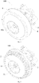
Fig. 1 is an exploded view of an electric fan according to an embodiment of the present disclosure; -
Fig. 2 is an assembly view of the electric fan shown inFig. 1 ; -
Fig. 3 is another schematic view of the electric fan shown inFig. 2 , without showing a cover; -
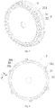
Fig. 4 is a front view of the electric fan shown inFig. 1 ; -
Fig. 5 is a sectional view taken along line A-A inFig. 4 ; -
Fig. 6 is an enlarged view of portion B boxed inFig. 5 ; -
Fig. 7 is an assembly view of a diffuser and a refluxer shown inFig. 1 ; and -
Fig. 8 is a front view of a diffuser inFig. 1 . -
- 100: electric fan;
- 1: cover; 10a: air inlet;
- 2: impeller;
- 3: diffuser; 30: diffuser flow passage;
- 30a: inlet of diffuser flow passage; 30b: outlet of diffuser flow passage;
- 31: diffuser body; 311: fitting protrusion; 31a: mounting groove;
- 32: vane;
- 4: refluxer; 40: refluxer flow passage; 41: assembling groove;
- 40a: inlet of refluxer flow passage; 40b: outlet of refluxer flow passage;
- 5: electric motor; 51: electric motor shaft; 52: mounting block;
- 6: shaft head nut; 7: washer; 8: connecting member.
- Embodiments of the present disclosure will be described in detail and examples of the embodiments will be illustrated in the drawings, where same or similar reference numerals are used to indicate same or similar members or members with same or similar functions. The embodiments described herein with reference to drawings are explanatory, illustrative, and used to generally understand the present disclosure. The embodiments shall not be construed to limit the present disclosure.
- In the specification, unless specified or limited otherwise, relative terms such as "central", "length", "thickness", "front", "rear", "inner", "outer", "axial", "radial", "circumferential", "toroidal" as well as derivative thereof should be construed to refer to the orientation as then described or as shown in the drawings under discussion. These relative terms are for convenience of description and do not require that the present disclosure be constructed or operated in a particular orientation. Furthermore, in the description of the present disclosure, the term "a plurality of' means two or more than two, unless specified otherwise.
- In the present disclosure, unless specified or limited otherwise, the terms "connected," "coupled" and the like are used broadly, and may be, for example, fixed connections, detachable connections, or integral connections; may also be mechanical or electrical connections; may also be direct connections or indirect connections via intervening structures; may also be inner communications of two elements. These having ordinary skills in the art should understand the specific meanings in the present disclosure according to specific situations.
- An
electric fan 100 according to embodiments of a first aspect of the present disclosure will be described below with reference toFigs. 1 to 8 . - As illustrated in
Figs. 1 to 8 , theelectric fan 100 according to embodiments of the first aspect of the present disclosure includes acover 1, animpeller 2, adiffuser 3 and arefluxer 4. - The
cover 1 has an open side. Theimpeller 2 is disposed in thecover 1. Thediffuser 3 includes adiffuser body 31 and a plurality ofvanes 32. Thediffuser body 31 is located at a side of theimpeller 2 adjacent to thecover 1. The plurality ofvanes 32 are disposed at an end of thediffuser body 31 adjacent toimpeller 2, and the plurality of vanes are spaced apart from one another along an outer circumference of theimpeller 2. An outlet angle of eachvane 32 is denoted as β, and β satisfies: 45°≤β≤90°. Therefluxer 4 is disposed at an end of thediffuser body 31 away from theimpeller 2. It should be noted herein that, the direction "outside" is a direction away from a central axis of theelectric fan 100, and an opposite direction thereof is defined as "inside". - For example, as illustrated in
Figs. 1-3 and8 , a rear side of thecover 1 is completely opened, and both theimpeller 2 anddiffuser 3 are disposed in thecover 1. Thediffuser body 31 is located at a rear side of theimpeller 2, the plurality of vanes are disposed at a front end of thediffuser body 31, and therefluxer 4 is disposed at a rear end of thediffuser body 31. Since the outlet angle β of eachvane 32 of thediffuser 3 satisfies 45°≤β≤90°, the outlet angle β of thevane 32 is relatively large, the vane can control flow of airflow to ensure the aerodynamic performance of theelectric fan 100, and a tangential velocity component of the airflow diffused by thediffuser 3 is reduced to reduce the flow velocity of the airflow, thereby reducing the resistance losses of the airflow, and promoting the performance of theelectric fan 100. It should be noted herein that, "the outlet angle β of thevane 32" is understood as an included angle between a tangent to a mean camber line of thevane 32 at the outlet along an airflow direction and a circumferential direction, and the "mean camber line" refers to a middle line of a section of thevane 32 along a streamline direction thereof. It could be understood that, thevane 32 and theimpeller 2 may be located in the same cross section of theelectric fan 100, in which case thevane 32 and theimpeller 2 are radially opposite to each other, as illustrated inFig. 5 ; certainly, thevane 32 and theimpeller 2 may also be located in different cross sections, in which case thevane 32 and theimpeller 2 are axially staggered to each other. - Specifically, when the
electric fan 100 is in operation, theimpeller 2 rotates at a high speed, an external air outside theelectric fan 100 may enter thecover 1 through anair inlet 10a in a front side of thecover 1, and is rotated with rotation of theimpeller 2, such that the air obtains a certain amount of energy; the air is rotated to an outer edge of theimpeller 2 and flows to thediffuser 3 under a centrifugal force of inertia during the rotation of the air; thediffuser 3 converts kinetic energy of the air into static pressure energy; and then therefluxer 4 functions to guide and rectify to some extent the air out of thediffuser 3. In the above-described process, the outlet angle β of eachvane 32 of thediffuser 3 satisfies 45°≤β≤90°, and the outlet angle β is relatively large, such that thevane 32 is curved to a radial direction of thediffuser 3 at the outlet of the vane, the tangential velocity component of the airflow diffused by thediffuser 3 is reduced, the flow velocity of the airflow is reduced, and more kinetic energy is converted into static pressure energy, thereby promoting a diffusion coefficient of the diffuser 3 (which may be understood as a ratio of air pressure at the outlet of thediffuser 3 to air pressure at the inlet of the diffuser 3); moreover, energy losses of the air flowing within thediffuser 3 is reduced, and the resistance losses of the airflow is reduced, thereby further improving the efficiency of theelectric fan 100 and promoting the performance of theelectric fan 100. - For the
electric fan 100 according to embodiments of the present disclosure, by disposing thevanes 32 of thediffuser 3 at the outer circumference of theimpeller 2 and enabling the outlet angle β of eachvane 32 to satisfy 45°≤β≤90°, a tangential flow velocity of the airflow is reduced while ensuring aerodynamic performance of theelectric fan 100, such that flow losses of the airflow are reduced, the efficiency of theelectric fan 100 is improved, and the performance of theelectric fan 100 is promoted. - In one embodiment of the present disclosure, each
vane 32 deviates from a radial direction of theimpeller 2, and eachvane 32 protrudes in a direction away from a datum line, and the datum line is a connection line of an end of thevane 32 adjacent to a center of theimpeller 2 and the center of theimpeller 2. For example, as illustrated inFigs. 1 ,3 and8 , an extending direction of eachvane 32 deviates from the radial direction of theimpeller 2, and eachvane 32 protrudes in a direction away from a datum line from inside to outside, the datum line is a connection line of an inlet end of the vane 32 (i.e. the end of thevane 32 adjacent to the center of the impeller 2) and the center of theimpeller 2. In this case, an inlet angle of the vane 32 (an included angle between a tangent to the mean camber line of thevane 32 at the inlet along the airflow direction and the circumferential direction) is smaller than the outlet angle β of thevane 32, and a vane angle (an included angle between a tangent to the mean camber line of thevane 32 along the airflow direction and the circumferential direction) increases from inside to outside, such that the tangential flow velocity of the airflow decreases gradually, the flow velocity of the airflow is reduced, and the flow losses of the airflow are reduced, thereby promoting the performance of theelectric fan 100. - In one embodiment of the present disclosure, two
adjacent vanes 32 define a diffuser flow passage 30 therebetween, a diffusion degree of the diffuser flow passage 30 is denoted as Δ1, and the Δ1 satisfies:
outlet 30b of the diffuser flow passage, and L1 is a length of the diffuser flow passage 30. For example, as illustrated inFigs. 5 to 8 , a front end of thevane 32 of thediffuser 3 may abuts against an inner wall surface of thecover 1, twoadjacent vanes 32 and thecover 1 collectively define the diffuser flow passage 30, the diffusion degree Δ1 of the diffuser flow passage 30 satisfies
adjacent vanes 32 has sufficient control effect on the flow of the airflow under the premise of ensuring the diffusion coefficient of thediffuser 3, so as to avoid turbulent flow of the airflow resulting from insufficient control of thediffuser 3 on the flow of the airflow, thereby promoting the aerodynamic performance of theelectric fan 100. It should be noted herein that, the "length of the diffuser flow passage 30" is a length of a central axis of the diffuser flow passage 30. - According to the present invention, a cross-sectional area of the diffuser flow passage 30 linearly increases in a direction from the inlet 30a of the diffuser flow passage to the
outlet 30b of the diffuser flow passage; the diffuser flow passage 30 includes a first flow passage and a second flow passage (not shown) sequentially connected in the direction from the inlet 30a of the diffuser flow passage to theoutlet 30b of the diffuser flow passage, a cross-sectional area of the first flow passage linearly increases, and an increase rate of a cross-sectional area of the second flow passage is less than an increase rate of the cross-sectional area of the first flow passage. That is to say, from the inlet 30a of the diffuser flow passage through the diffuser flow passage 30 to theoutlet 30b of the diffuser flow passage, a cross-sectional area of the diffuser flow passage 30 linearly increases from A1 to A2, in which case the cross-sectional area of the diffuser flow passage 30 is gradually varying; in addition, the cross-sectional area of the first flow passage linearly increases, and the increase rate of the cross-sectional area of the second flow passage is less than the increase rate of the cross-sectional area of the first flow passage, in which case the cross-sectional area of the second flow passage may linearly increase or curvilinearly increase, which is not limited. Thus, by setting the cross-sectional area of the diffuser flow passage 30 to increase linearly, a flow separation phenomenon of the airflow within the diffuser flow passage 30 can be alleviated, such that flow separation losses of the airflow within the diffuser flow passage 30 are reduced, and energy losses of the air flowing within thediffuser 3 are further reduced, thereby promoting the performance of theelectric fan 100. By setting the cross-sectional area of the first flow passage of the diffuser flow passage 30 to increase linearly, and setting the increase rate of the cross-sectional area of the second flow passage thereof to be less than the increase rate of the cross-sectional area of the first flow passage, the flow separation phenomenon of the airflow within the second flow passage can be further alleviated, thereby further promoting the performance of theelectric fan 100. - In one optional embodiment of the present disclosure, a thickness of an end of each
vane 32 adjacent to the center of theimpeller 2 is less than a thickness of an end thereof away from the center of theimpeller 2. For example, as illustrated inFigs. 1 ,3 ,7 and 8 , when the airflow flows out of theimpeller 2 and into thediffuser 3, the airflow flows from the inlet end of thevane 32 to the outlet end of the vane 32 (i.e. the end of thevane 32 away from the center of the impeller 2) along the extending direction of thevane 32. The thickness of the inlet end of thevane 32 is less than the thickness of the outlet end of thevane 32, and the thickness of the inlet end of thevane 32 is thinner, such that it is convenient for the airflow to smoothly flow into thediffuser 3 via the inlet end of thevane 32, obstruction of the airflow entering thediffuser 3 is reduced, and energy consumption of the airflow is reduced, thereby broadening the high-efficiency operation range of theelectric fan 100, improving capacity of theelectric fan 100 adapting work conditions, and promoting applicability of theelectric fan 100. It should be noted herein that, the "thickness" refers to a length of thevane 32 in a normal direction of the mean camber line thereof. - Further, as illustrated in
Fig. 8 , the thickness of thevane 32 is optionally increased uniformly from the inlet end of thevane 32 to the outlet end of thevane 32 along the extending direction of thevane 32, such that the cross-sectional area of the diffuser flow passage 30 defined between twoadjacent vanes 32 varies uniformly, thereby further reducing the flow separation losses of the airflow. - In one embodiment of the present disclosure, the end of each
vane 32 away from the center of theimpeller 2 extends out of an outer circumferential wall of thediffuser body 31. For example, as illustrated inFigs. 1 ,3 ,7 and 8 , thediffuser body 31 may be a substantially ring-shaped structure, the plurality ofvanes 32 are disposed at an outer edge of thediffuser body 31, and the outlet end of eachvane 32 extends outwards and beyond the outer circumferential wall of thediffuser body 31, such that the length of thevane 32 is appropriately lengthened, and the control effect on the flow of the airflow by thevane 32 is enhanced. It should be noted herein that, the "length" refers to a length of the mean camber line of thevane 32. - In some embodiments of the present disclosure, the
refluxer 4 is disposed at the outer circumference of thediffuser body 31 and therefluxer 4 is spaced apart from thediffuser body 31 to define arefluxer flow passage 40. For example, as illustrated inFigs. 1 and5-7 , therefluxer 4 may be a ring-shaped structure, and therefluxer 4 is coaxially disposed outside thediffuser body 31, such that therefluxer flow passage 40 is formed as a substantially ring-shaped structure, which has a simple and compact structure and is easy to implement. Moreover, a spacing between therefluxer 4 and thediffuser body 31 forms therefluxer flow passage 40, such that therefluxer flow passage 40 forms an enclosed flow passage, and presence of a sudden expansion portion of therefluxer flow passage 40 is avoided, thereby further promoting the aerodynamic performance of theelectric fan 100. - In some embodiments of the present disclosure, a diffusion degree of the
refluxer flow passage 40 is denoted as Δ2, and the Δ2 satisfies:
inlet 40a of the refluxer flow passage, A4 is a cross-sectional area at anoutlet 40b of the refluxer flow passage, and L2 is a length of therefluxer flow passage 40. For example, as illustrated inFigs. 5 and 6 , a front end of therefluxer 4 and thediffuser body 31 define theinlet 40a of the refluxer flow passage therebetween, while a rear end of therefluxer 4 and thediffuser body 31 define theoutlet 40b of the refluxer flow passage therebetween. By setting the diffusion degree Δ2 of therefluxer flow passage 40 to satisfy
refluxer flow passage 40 being a contracted flow passage can be avoided, and the flow losses of the airflow within therefluxer flow passage 40 can be reduced, thereby facilitating decrease of the energy consumption of the airflow and promoting the performance of theelectric fan 100. - Optionally, the cross-sectional area of the
refluxer flow passage 40 may remain constant in a direction from theinlet 40a of the refluxer flow passage to theoutlet 40b of the refluxer flow passage; or the cross-sectional area of therefluxer flow passage 40 may also increase uniformly in the direction from theinlet 40a of the refluxer flow passage to theoutlet 40b of the refluxer flow passage. That is to say, A3 ≤A4, i.e. the cross-sectional area of therefluxer flow passage 40 may always be A3 (in this case, A4=A3) from theinlet 40a of the refluxer flow passage through therefluxer flow passage 40 to theoutlet 40b of the refluxer flow passage, or the cross-sectional area of therefluxer flow passage 40 uniformly increases from A3 to A4 (in this case, A3<A4). Thus, by setting the cross-sectional area of therefluxer flow passage 40 to remain constant or increase uniformly, a flow separation phenomenon of the airflow within therefluxer flow passage 40 can be alleviated, such that flow separation losses of the airflow within therefluxer flow passage 40 are reduced, and energy losses of the air flowing within therefluxer 4 is further reduced, thereby promoting the performance of theelectric fan 100. - Further, a side of the
refluxer 4 away from theimpeller 2 is provided with anelectric motor 5, and theoutlet 40b of the refluxer flow passage faces theelectric motor 5. For example, as illustrated inFigs. 5 and 6 , theelectric motor 5 is disposed at a rear side of therefluxer 4, and theoutlet 40b of the refluxer flow passage faces theelectric motor 5, such that the airflow out of therefluxer 4 can dissipate heat of theelectric motor 5, operation condition of theelectric motor 5 is improved, thereby solving temperature rise problem of theelectric fan 100 and prolonging service life of theelectric fan 100. Moreover, theoutlet 40b of the refluxer flow passage is a substantially ring-shaped outlet, such that the heat of theelectric motor 5 can be dissipated more evenly. Meanwhile, theoutlet 40b of the refluxer flow passage is disposed outside theelectric motor 5, such that relatively large obstruction to the airflow generated by the components within theelectric motor 5, such as stator and rotor structure, coil and carbon brush, etc., due to heat dissipation of theelectric motor 5 which requires the airflow to flow into an interior of theelectric motor 5, can be avoided. This obstruction will affect the flow of the airflow within an upstream flow passage such as therefluxer flow passage 40. In other words, the above arrangement way of theoutlet 40b of the refluxer flow passage reduces the flow losses of the airflow, thereby promoting the efficiency of theelectric fan 100. - Optionally, as illustrated in
Figs. 5 and 6 , therefluxer flow passage 40 extends obliquely along an axial direction of theimpeller 2, from theinlet 40a of the refluxer flow passage to theoutlet 40b of the refluxer flow passage and in a direction approaching a central axis of theimpeller 2. That is to say, therefluxer flow passage 40 extends obliquely from theinlet 40a of the refluxer flow passage to theoutlet 40b of the refluxer flow passage along the axial direction of theimpeller 2 from outside to inside, such that theoutlet 40b of the refluxer flow passage faces theelectric motor 5 to dissipate the heat of theelectric motor 5, and a structure of therefluxer flow passage 40 is further simplified. - In some embodiments of the present disclosure, one of the
diffuser body 31 and therefluxer 4 is provided with at least onefitting protrusion 311, and the other one of thediffuser body 31 and therefluxer 4 defines at least one assemblinggroove 41 fitted with thefitting protrusion 311. Thus, through the fitting between thefitting protrusion 311 and the assemblinggroove 41, disassembly and assembly of thediffuser 3 and therefluxer 4 are facilitated, and the structure of thediffuser 3 and therefluxer 4 after assembly is more compact. - For example, in examples illustrated in
Figs. 1-4 ,7 and 8 , sixfitting protrusions 311 are provided on the outer circumferential wall of thediffuser body 31, and the sixfitting protrusions 311 may be distributed at even intervals along a circumferential direction of thediffuser body 31, eachfitting protrusion 311 extends rearwards from the outer circumferential wall of thediffuser body 31 along the axial direction of theelectric fan 100. Therefluxer 4 is correspondingly provided with six assemblinggrooves 41, each assemblinggroove 41 is formed by recessing a partial edge of therefluxer 4 rearwards along the axial direction of theelectric fan 100. The sixfitting protrusions 311 are fitted in the six assemblinggrooves 41 in one-to-one correspondence, thereby facilitating the disassembly and assembly between thediffuser 3 and therefluxer 4. It could be understood that, the number of thefitting protrusions 311 and the assemblinggrooves 41, and their arrangement way can be set according to actual requirements, so as to better satisfy the actual application. - In one embodiment of the present disclosure, the
cover 1 defines a throughair inlet 10a, theair inlet 10a is circular, a diameter of theair inlet 10a is denoted as d, and d satisfies: d≥40mm. For example, as illustrated inFigs. 1 and2 , theair inlet 10a is defined in the front side of thecover 1. When theelectric fan 100 is in operation, theimpeller 2 rotates, such that a certain amount of negative pressure is produced at theair inlet 10a, and the external air flows into theelectric fan 100 through theair inlet 10a. By setting the diameter of theair inlet 10a to be denoted as d and satisfy d≥40mm, air volume of theelectric fan 100 can be promoted at the same rotating speed of theimpeller 2; or in the case where a certain amount of air volume is required, the rotating speed of theimpeller 2 can be reduced, so as to reduce noise of theimpeller 2. - The
electric fan 100 according to one specific embodiment of the present disclosure will be described in detail below with reference toFigs. 1 to 8 . - As illustrated in
Figs. 1 to 8 , theelectric fan 100 includes thecover 1, theimpeller 2, thediffuser 3, therefluxer 4, and theelectric motor 5 that are arranged from front to rear. The front side of thecover 1 defines a throughair inlet 10a, theair inlet 10a is a circular opening, and the diameter d of theair inlet 10a ≥40mm. The rear side of thecover 1 is completely open, and thecover 1 and therefluxer 4 can be connected through an interference fit, such that thecover 1 and therefluxer 4 define a cavity therebetween, and theimpeller 2 and thediffuser 3 are both disposed in the above cavity. The outer circumferential wall of thediffuser body 31 is provided with sixfitting protrusions 311 at even intervals along the circumferential direction of thediffuser body 31, and therefluxer 4 is correspondingly provided with six assemblinggrooves 41, such that thediffuser 3 is connected to therefluxer 4 through the fitting between thefitting protrusions 311 and the assemblinggrooves 41. Furthermore, theelectric motor 5 has anelectric motor shaft 51. Theelectric motor shaft 51 penetrates thediffuser 3 and theimpeller 2 in turn from rear to front, and a front end of theelectric motor shaft 51 is provided with ashaft head nut 6, so as to mount theimpeller 2 onto theelectric motor shaft 51. A rear end of theelectric motor shaft 51 is provided with a mountingblock 52. The mountingblock 52 is placed in a mountinggroove 31a in the rear end of thediffuser 3, and theelectric motor 5 is fixedly connected to thediffuser 3 through a connecting member 8. For example, the connecting member 8 may optionally be a screw, and so on. Additionally, theimpeller 2 and a shaft shoulder of theelectric motor shaft 51 may be provided with awasher 7 therebetween. - As illustrated in
Figs. 1 to 8 , thediffuser 3 includes thediffuser body 31 and the plurality ofvanes 32. Thediffuser body 31 may be a substantially ring-shaped structure, the plurality ofvanes 32 are disposed at the front end of thediffuser body 31, the plurality ofvanes 32 are spaced apart evenly from one another along the outer circumference of theimpeller 2, and the plurality ofvanes 32 and theimpeller 2 are located in the same cross section of theelectric fan 100, in which case thevane 32 is radially opposite to theimpeller 2. Eachvane 32 extends from inside to outside, and beyond the outer edge of thediffuser body 31. The vane angle of eachvane 32 increases from inside to outside, and the outlet angle β of thevane 32 satisfies 45°≤β≤90°. The thickness of eachvane 32 increases uniformly from inside to outside. Meanwhile, the front end of eachvane 32 abuts against the inner wall surface of thecover 1, such that twoadjacent vanes 32 and thecover 1 collectively define the diffuser flow passage 30 thereamong. The diffusion degree Δ1 of the diffuser flow passage 30 satisfies Δ1< 14°(
outlet 30b of the diffuser flow passage, and L1 is the length of the diffuser flow passage 30), and the cross-sectional area of the diffuser flow passage 30 increases linearly from A1 to A2, from the inlet 30a of the diffuser flow passage through the diffuser flow passage 30 to theoutlet 30b of the diffuser flow passage. - As illustrated in
Figs. 1 to 8 , therefluxer 4 may be ring-shaped structure, and therefluxer 4 is coaxially disposed outside thediffuser body 31 at an interval, such that therefluxer 4 and thediffuser body 31 define therefluxer flow passage 40 therebetween. The diffusion degree Δ2 of therefluxer flow passage 40 is < 14° (
inlet 40a of the refluxer flow passage, A4 is the cross-sectional area at theoutlet 40b of the refluxer flow passage, and the L2 is the length of the refluxer flow passage 40), and the cross-sectional area of therefluxer flow passage 40 increases uniformly from A3 to A4 from theinlet 40a of the refluxer flow passage through therefluxer flow passage 40 to theoutlet 40b of the refluxer flow passage. Therefluxer flow passage 40 extends obliquely from theinlet 40a of the refluxer flow passage to theoutlet 40b of the refluxer flow passage along a front-and-rear direction from outside to inside, such that theoutlet 40b of the refluxer flow passage faces theelectric motor 5 to dissipate the heat of theelectric motor 5. - When the
electric fan 100 is in operation, theelectric motor shaft 51 drives theimpeller 2 to rotate at a high speed, the external air enters theimpeller 2 through theair inlet 1 0a, and is rotated with rotation of theimpeller 2, such that the air obtains a certain amount of energy; the air is rotated to the outer edge of theimpeller 2 and flows into the diffuser flow passage 30 under the centrifugal force of inertia during the rotation of the air; thediffuser 3 converts kinetic energy of the air into static pressure energy due to linear increase of the cross-sectional area of the diffuser flow passage 30; and then therefluxer 40 guides and diffuses the air out of thediffuser 3, and the air flows out of therefluxer flow passage 40 and dissipates the heat of theelectric motor 5. - For the
electric fan 100 according to the specific embodiments of the present disclosure, both of the diffuser flow passage 30 and therefluxer flow passage 40 can reduce the flow losses of the airflow, so as to reduce the energy consumption, promote the performance of theelectric fan 100, and improve the applicability of theelectric fan 100; meanwhile, the airflow can perform good heat dissipation of theelectric motor 5, prolonging the service life of theelectric fan 100; moreover, the air volume of theelectric fan 100 is relatively large at the same rotating speed of theimpeller 2, or the noise of theelectric fan 100 is relatively low in the case of a certain amount of air volume. - The vacuum cleaner (not shown) according to embodiments of a second aspect of the present disclosure includes an
electric fan 100 according to the above embodiments of the first aspect of the present disclosure. - Specifically, for example, a vacuum cleaner defines a suction port and a discharge port, the
electric fan 100 is mounted in the vacuum cleaner, the suction port of the vacuum cleaner is in communication with theair inlet 10a of theelectric fan 100, and the vacuum cleaner is internally provided with a filter device and a dust collecting device. When the vacuum cleaner is in operation, theelectric fan 100 operates, such that a certain amount of negative pressure is produced at the suction port, the surrounding dust laden air is sucked into the vacuum cleaner through the suction port, and filtered by the filter device, such that the foreign matter such as the dust is filtered and collected in the dust collecting device. The clean air then flows into theelectric fan 100 through theair inlet 10a, and finally discharged though the discharge port of the vacuum cleaner. - For the vacuum cleaner according to embodiments of the second aspect of the present disclosure, by employing the above
electric fan 100, energy consumption of the vacuum cleaner is reduced, efficiency of the vacuum cleaner is improved, and noise of the vacuum cleaner is reduced, thereby improving sound quality of the vacuum cleaner, and promoting selling points of the vacuum cleaner. - Other constitutions and operations of the vacuum cleaner according to the present disclosure is well known by those skilled in the art, which will not be described in detail herein.
- Reference throughout this specification to "an embodiment," "some embodiments," "an illustrative embodiment," "an example," "a specific example," or "some examples," means that a particular feature, structure, material, or characteristic described in connection with the embodiment or example is included in at least one embodiment or example of the present disclosure. Thus, the appearances of the phrases in various places throughout this specification are not necessarily referring to the same embodiment or example of the present disclosure. Furthermore, the particular features, structures, materials, or characteristics may be combined, as defined by the appended claims, in one or more embodiments or examples.
- Although embodiments of the present disclosure have been shown and illustrated, it shall be understood by those skilled in the art that various changes, modifications, alternatives and variants without departing from the scope of the present invention are acceptable. The scope of the present invention is solely defined by the claims.
Claims (12)
- An electric fan (100), comprising:a cover (1) having an open side;an impeller (2) disposed in the cover (1);a diffuser (3) comprising a diffuser body (31) and a plurality of vanes (32), the diffuser body (31) being located at a side of the impeller (2) adjacent to the cover (1), the plurality of vanes (32) being disposed at an end of the diffuser body (31) adjacent to the impeller (2) and spaced apart from one another along an outer circumference of the impeller (2), wherein an outlet angle (β) of each vane (32) is in the range 45° to 90°, wherein the outlet angle (β) of a respective vane (32) is the included angle between a tangent to a mean camber line of the respective vane (32) at the outlet along an airflow direction and a circumferential direction; anda refluxer (4) disposed at an end of the diffuser body (31) away from the impeller (2); andcharacterized in thattwo adjacent vanes (32) define a diffuser flow passage (30) therebetween having a cross-sectional area that linearly increases in a direction from the inlet (30a) of the diffuser flow passage (30) to the outlet (30b) of the diffuser flow passage (30), and in that the diffuser flow passage (30) comprises a first flow passage and a second flow passage sequentially connected in the direction from the inlet (30a) of the diffuser flow passage (30) to the outlet (30b) of the diffuser flow passage (30), a cross-sectional area of the first flow passage linearly increases, and an increase rate of a cross-sectional area of the second flow passage is less than an increase rate of the cross-sectional area of the first flow passage.
- The electric fan according to claim 1, wherein each vane (32) deviates from a radial direction of the impeller (2), and each vane (32) protrudes in a direction away from a datum line from inside to outside, and the datum line is a connection line of an end of the vane (32) adjacent to a center of the impeller (2) and the center of the impeller (2).
- The electric fan according to any preceding claim, wherein a thickness of an end of each vane (32) adjacent to a center of the impeller (2) is less than a thickness of an end of the vane (32) away from the center of the impeller (2), and wherein an end of each vane (32) away from a center of the impeller (2) extends out of an outer circumferential wall of the diffuser body (31).
- The electric fan according to any preceding claim, wherein the refluxer (4) is disposed at an outer circumference of the diffuser body (31) and is spaced apart from the diffuser body (31) to define a refluxer flow passage (40).
- The electric fan according to claim 4, wherein:a diffusion degree (Δ1) of the diffuser flow passage (30) satisfies:
 a diffusion degree (Δ2) of the refluxer flow passage (40) satisfies:
- The electric fan according to claim 4 or 5, wherein a cross-sectional area of the refluxer flow passage (40) remains constant in a direction from the inlet of the refluxer flow passage (40) to the outlet of the refluxer flow passage (40).
- The electric fan according to claim 4 or 5, wherein the cross-sectional area of the refluxer flow passage (40) uniformly increases in the direction from the inlet of the refluxer flow passage (40) to the outlet of the refluxer flow passage (40).
- The electric fan according to any one of claims 4 to 7, wherein a side of the refluxer (4) away from the impeller (2) is provided with an electric motor, and the outlet of the refluxer flow passage (40) faces the electric motor.
- The electric fan according to claim 8, wherein the refluxer flow passage (40) obliquely extends along an axial direction of the impeller (2), from the inlet of the refluxer flow passage (40) to the outlet of the refluxer flow passage (40) and in a direction approaching a central axis of the impeller (2).
- The electric fan according to any one of claims 5 to 9, wherein one of the diffuser body (31) and the refluxer (4) is provided with at least one fitting protrusion (311), and the other one of the diffuser body(31) and the refluxer (4) defines at least one assembling groove (41) fitted with the fitting protrusion (311).
- The electric fan according to any preceding claim, wherein the cover (1) further defines a circular through air inlet (10a), having a diameter (d) of at least 40mm.
- A vacuum cleaner comprising an electric fan (100) according to any one of claims 1 to 11.
Applications Claiming Priority (2)
| Application Number | Priority Date | Filing Date | Title |
|---|---|---|---|
| CN201710146107.0A CN107061320B (en) | 2017-03-13 | 2017-03-13 | Electric fan and dust catcher with it |
| PCT/CN2017/083114 WO2018166052A1 (en) | 2017-03-13 | 2017-05-04 | Electric fan and vacuum cleaner having same |
Publications (3)
| Publication Number | Publication Date |
|---|---|
| EP3462039A1 EP3462039A1 (en) | 2019-04-03 |
| EP3462039A4 EP3462039A4 (en) | 2019-06-12 |
| EP3462039B1 true EP3462039B1 (en) | 2020-07-01 |
Family
ID=59622000
Family Applications (1)
| Application Number | Title | Priority Date | Filing Date |
|---|---|---|---|
| EP17900765.3A Active EP3462039B1 (en) | 2017-03-13 | 2017-05-04 | Electric fan and vacuum cleaner having same |
Country Status (4)
| Country | Link |
|---|---|
| US (1) | US11116367B2 (en) |
| EP (1) | EP3462039B1 (en) |
| CN (1) | CN107061320B (en) |
| WO (1) | WO2018166052A1 (en) |
Families Citing this family (5)
| Publication number | Priority date | Publication date | Assignee | Title |
|---|---|---|---|---|
| CN110513304B (en) * | 2018-05-22 | 2021-09-21 | 美的集团股份有限公司 | Centrifugal fan and dust collector |
| CN113074137B (en) * | 2020-01-06 | 2023-06-09 | 广东威灵电机制造有限公司 | Air supply device and dust collector |
| US11311153B1 (en) * | 2020-10-01 | 2022-04-26 | Hokwang Industries Co., Ltd. | Wind flow generating device adapted to hand dryer |
| CN114688045A (en) * | 2020-12-25 | 2022-07-01 | 广东美的白色家电技术创新中心有限公司 | Fan assembly and dust collector |
| DE102021115313A1 (en) * | 2021-06-14 | 2022-12-15 | Valeo Klimasysteme Gmbh | Fan device and heating, ventilation and/or air conditioning device for a motor vehicle |
Citations (1)
| Publication number | Priority date | Publication date | Assignee | Title |
|---|---|---|---|---|
| JP2008163821A (en) * | 2006-12-28 | 2008-07-17 | Toyota Central R&D Labs Inc | Centrifugal compressor |
Family Cites Families (17)
| Publication number | Priority date | Publication date | Assignee | Title |
|---|---|---|---|---|
| KR100409173B1 (en) * | 1995-06-26 | 2004-03-26 | 가부시끼가이샤 히다치 세이사꾸쇼 | Electric vacuum cleaner |
| WO1997019629A1 (en) * | 1995-11-24 | 1997-06-05 | Nilfisk A/S | A blower for a vacuum cleaner |
| US6425739B1 (en) * | 2000-03-27 | 2002-07-30 | R. B. Kanalflakt, Inc. | In-line centrifugal fan |
| JP4596995B2 (en) * | 2005-06-24 | 2010-12-15 | 日立アプライアンス株式会社 | Electric blower and vacuum cleaner equipped with the same |
| KR100721305B1 (en) * | 2005-11-28 | 2007-05-28 | 삼성광주전자 주식회사 | Fan assembly for vacuum cleaner |
| DE202006020187U1 (en) * | 2006-06-29 | 2007-11-29 | Deutsches Zentrum für Luft- und Raumfahrt e.V. | centrifugal compressors |
| JP5048701B2 (en) * | 2009-03-10 | 2012-10-17 | 三菱電機株式会社 | Electric blower and electric vacuum cleaner |
| CN101846087B (en) * | 2010-05-11 | 2011-09-14 | 东元总合科技(杭州)有限公司 | Centrifugal fan and closed motor with same |
| JP5601358B2 (en) * | 2012-09-13 | 2014-10-08 | 三菱電機株式会社 | Electric blower and vacuum cleaner |
| KR102099346B1 (en) * | 2014-01-02 | 2020-04-09 | 삼성전자주식회사 | Fan motor assembly and vacuum cleaner having the same |
| EP2961038B1 (en) * | 2014-06-05 | 2019-12-11 | Samsung Electronics Co., Ltd. | Vacuum cleaner with motor assembly |
| KR102233312B1 (en) * | 2014-06-05 | 2021-03-29 | 삼성전자주식회사 | Motor Assembly |
| JP6417771B2 (en) * | 2014-07-31 | 2018-11-07 | 日本電産株式会社 | Electric blower |
| KR102330551B1 (en) * | 2015-03-12 | 2021-11-24 | 엘지전자 주식회사 | Vacuum suntion unit |
| CN106468286A (en) * | 2015-08-19 | 2017-03-01 | 德昌电机(深圳)有限公司 | Blower fan and its bubbler |
| EP3438461A4 (en) * | 2016-03-29 | 2019-03-13 | Mitsubishi Electric Corporation | Electric fan and electric vacuum cleaner equipped with same |
| CN106224269A (en) * | 2016-10-10 | 2016-12-14 | 东莞市大可智能科技有限公司 | A kind of novel pipeline blower fan and application thereof |
-
2017
- 2017-03-13 CN CN201710146107.0A patent/CN107061320B/en active Active
- 2017-05-04 EP EP17900765.3A patent/EP3462039B1/en active Active
- 2017-05-04 WO PCT/CN2017/083114 patent/WO2018166052A1/en unknown
-
2018
- 2018-12-27 US US16/233,116 patent/US11116367B2/en active Active
Patent Citations (1)
| Publication number | Priority date | Publication date | Assignee | Title |
|---|---|---|---|---|
| JP2008163821A (en) * | 2006-12-28 | 2008-07-17 | Toyota Central R&D Labs Inc | Centrifugal compressor |
Also Published As
| Publication number | Publication date |
|---|---|
| CN107061320B (en) | 2019-04-02 |
| CN107061320A (en) | 2017-08-18 |
| US20190125146A1 (en) | 2019-05-02 |
| EP3462039A1 (en) | 2019-04-03 |
| EP3462039A4 (en) | 2019-06-12 |
| US11116367B2 (en) | 2021-09-14 |
| WO2018166052A1 (en) | 2018-09-20 |
Similar Documents
| Publication | Publication Date | Title |
|---|---|---|
| EP3462039B1 (en) | Electric fan and vacuum cleaner having same | |
| EP1443215B1 (en) | Integral tip seal in a fan-shroud structure | |
| US6435828B1 (en) | Split blade radial fan | |
| EP1923572A2 (en) | Electric blower and electric cleaner using the same | |
| EP0602007B1 (en) | Vacuum cleaner having an impeller and diffuser | |
| US20090185906A1 (en) | Centrifugal impeller | |
| US20210025606A1 (en) | Air cleaner | |
| JP2000145690A (en) | Electric blower and vacuum cleaner with the same | |
| WO2008082397A1 (en) | Reduced tip clearance losses in axial flow fans | |
| JP6758243B2 (en) | Electric blower and vacuum cleaner equipped with it | |
| WO2019011315A1 (en) | Centrifugal vane wheel and centrifugal fan comprising same and dust collector | |
| JP2011202560A (en) | Electric blower and electric vacuum cleaner using the same | |
| CN106837859B (en) | Draught fan impeller and centrifugal blower | |
| CN110886708A (en) | Backward-inclined silent fan | |
| CN212899134U (en) | Motor fan system of dust collector and fixed impeller thereof | |
| CN214366855U (en) | Combined fan and cooking utensil | |
| WO2019144736A1 (en) | Impeller, fan assembly and electrical appliance | |
| WO2023108921A1 (en) | Fan and cleaning device with same | |
| JP6553360B2 (en) | Electric blower and vacuum cleaner equipped with the same | |
| CN215293002U (en) | Impeller assembly, multi-wing centrifugal fan and household appliance | |
| CN100489402C (en) | Deep kitchen ventilator | |
| CN218717696U (en) | Centrifugal wind wheel blade structure with noise elimination function | |
| CN219509861U (en) | High-ventilation low-noise centrifugal ventilator | |
| CN211174672U (en) | Backward-inclined silent fan | |
| WO2023097481A1 (en) | Fan assembly and vacuum cleaner having same |
Legal Events
| Date | Code | Title | Description |
|---|---|---|---|
| STAA | Information on the status of an ep patent application or granted ep patent |
Free format text: STATUS: THE INTERNATIONAL PUBLICATION HAS BEEN MADE |
|
| PUAI | Public reference made under article 153(3) epc to a published international application that has entered the european phase |
Free format text: ORIGINAL CODE: 0009012 |
|
| STAA | Information on the status of an ep patent application or granted ep patent |
Free format text: STATUS: REQUEST FOR EXAMINATION WAS MADE |
|
| 17P | Request for examination filed |
Effective date: 20181228 |
|
| AK | Designated contracting states |
Kind code of ref document: A1 Designated state(s): AL AT BE BG CH CY CZ DE DK EE ES FI FR GB GR HR HU IE IS IT LI LT LU LV MC MK MT NL NO PL PT RO RS SE SI SK SM TR |
|
| AX | Request for extension of the european patent |
Extension state: BA ME |
|
| A4 | Supplementary search report drawn up and despatched |
Effective date: 20190513 |
|
| RIC1 | Information provided on ipc code assigned before grant |
Ipc: F04D 29/42 20060101ALI20190507BHEP Ipc: F04D 25/08 20060101ALI20190507BHEP Ipc: F04D 29/66 20060101ALI20190507BHEP Ipc: F04D 17/16 20060101ALI20190507BHEP Ipc: F04D 29/44 20060101AFI20190507BHEP |
|
| GRAP | Despatch of communication of intention to grant a patent |
Free format text: ORIGINAL CODE: EPIDOSNIGR1 |
|
| STAA | Information on the status of an ep patent application or granted ep patent |
Free format text: STATUS: GRANT OF PATENT IS INTENDED |
|
| DAV | Request for validation of the european patent (deleted) | ||
| DAX | Request for extension of the european patent (deleted) | ||
| INTG | Intention to grant announced |
Effective date: 20200310 |
|
| GRAS | Grant fee paid |
Free format text: ORIGINAL CODE: EPIDOSNIGR3 |
|
| GRAA | (expected) grant |
Free format text: ORIGINAL CODE: 0009210 |
|
| STAA | Information on the status of an ep patent application or granted ep patent |
Free format text: STATUS: THE PATENT HAS BEEN GRANTED |
|
| AK | Designated contracting states |
Kind code of ref document: B1 Designated state(s): AL AT BE BG CH CY CZ DE DK EE ES FI FR GB GR HR HU IE IS IT LI LT LU LV MC MK MT NL NO PL PT RO RS SE SI SK SM TR |
|
| REG | Reference to a national code |
Ref country code: CH Ref legal event code: EP Ref country code: AT Ref legal event code: REF Ref document number: 1286453 Country of ref document: AT Kind code of ref document: T Effective date: 20200715 |
|
| REG | Reference to a national code |
Ref country code: IE Ref legal event code: FG4D |
|
| REG | Reference to a national code |
Ref country code: DE Ref legal event code: R096 Ref document number: 602017019186 Country of ref document: DE |
|
| REG | Reference to a national code |
Ref country code: CH Ref legal event code: NV Representative=s name: KIRKER AND CIE S.A., CH |
|
| REG | Reference to a national code |
Ref country code: LT Ref legal event code: MG4D |
|
| PG25 | Lapsed in a contracting state [announced via postgrant information from national office to epo] |
Ref country code: BG Free format text: LAPSE BECAUSE OF FAILURE TO SUBMIT A TRANSLATION OF THE DESCRIPTION OR TO PAY THE FEE WITHIN THE PRESCRIBED TIME-LIMIT Effective date: 20201001 |
|
| REG | Reference to a national code |
Ref country code: NL Ref legal event code: MP Effective date: 20200701 |
|
| REG | Reference to a national code |
Ref country code: AT Ref legal event code: MK05 Ref document number: 1286453 Country of ref document: AT Kind code of ref document: T Effective date: 20200701 |
|
| PG25 | Lapsed in a contracting state [announced via postgrant information from national office to epo] |
Ref country code: ES Free format text: LAPSE BECAUSE OF FAILURE TO SUBMIT A TRANSLATION OF THE DESCRIPTION OR TO PAY THE FEE WITHIN THE PRESCRIBED TIME-LIMIT Effective date: 20200701 Ref country code: GR Free format text: LAPSE BECAUSE OF FAILURE TO SUBMIT A TRANSLATION OF THE DESCRIPTION OR TO PAY THE FEE WITHIN THE PRESCRIBED TIME-LIMIT Effective date: 20201002 Ref country code: AT Free format text: LAPSE BECAUSE OF FAILURE TO SUBMIT A TRANSLATION OF THE DESCRIPTION OR TO PAY THE FEE WITHIN THE PRESCRIBED TIME-LIMIT Effective date: 20200701 Ref country code: NO Free format text: LAPSE BECAUSE OF FAILURE TO SUBMIT A TRANSLATION OF THE DESCRIPTION OR TO PAY THE FEE WITHIN THE PRESCRIBED TIME-LIMIT Effective date: 20201001 Ref country code: HR Free format text: LAPSE BECAUSE OF FAILURE TO SUBMIT A TRANSLATION OF THE DESCRIPTION OR TO PAY THE FEE WITHIN THE PRESCRIBED TIME-LIMIT Effective date: 20200701 Ref country code: SE Free format text: LAPSE BECAUSE OF FAILURE TO SUBMIT A TRANSLATION OF THE DESCRIPTION OR TO PAY THE FEE WITHIN THE PRESCRIBED TIME-LIMIT Effective date: 20200701 Ref country code: FI Free format text: LAPSE BECAUSE OF FAILURE TO SUBMIT A TRANSLATION OF THE DESCRIPTION OR TO PAY THE FEE WITHIN THE PRESCRIBED TIME-LIMIT Effective date: 20200701 Ref country code: PT Free format text: LAPSE BECAUSE OF FAILURE TO SUBMIT A TRANSLATION OF THE DESCRIPTION OR TO PAY THE FEE WITHIN THE PRESCRIBED TIME-LIMIT Effective date: 20201102 Ref country code: CZ Free format text: LAPSE BECAUSE OF FAILURE TO SUBMIT A TRANSLATION OF THE DESCRIPTION OR TO PAY THE FEE WITHIN THE PRESCRIBED TIME-LIMIT Effective date: 20200701 Ref country code: LT Free format text: LAPSE BECAUSE OF FAILURE TO SUBMIT A TRANSLATION OF THE DESCRIPTION OR TO PAY THE FEE WITHIN THE PRESCRIBED TIME-LIMIT Effective date: 20200701 |
|
| PG25 | Lapsed in a contracting state [announced via postgrant information from national office to epo] |
Ref country code: PL Free format text: LAPSE BECAUSE OF FAILURE TO SUBMIT A TRANSLATION OF THE DESCRIPTION OR TO PAY THE FEE WITHIN THE PRESCRIBED TIME-LIMIT Effective date: 20200701 Ref country code: LV Free format text: LAPSE BECAUSE OF FAILURE TO SUBMIT A TRANSLATION OF THE DESCRIPTION OR TO PAY THE FEE WITHIN THE PRESCRIBED TIME-LIMIT Effective date: 20200701 Ref country code: RS Free format text: LAPSE BECAUSE OF FAILURE TO SUBMIT A TRANSLATION OF THE DESCRIPTION OR TO PAY THE FEE WITHIN THE PRESCRIBED TIME-LIMIT Effective date: 20200701 Ref country code: IS Free format text: LAPSE BECAUSE OF FAILURE TO SUBMIT A TRANSLATION OF THE DESCRIPTION OR TO PAY THE FEE WITHIN THE PRESCRIBED TIME-LIMIT Effective date: 20201101 |
|
| PG25 | Lapsed in a contracting state [announced via postgrant information from national office to epo] |
Ref country code: NL Free format text: LAPSE BECAUSE OF FAILURE TO SUBMIT A TRANSLATION OF THE DESCRIPTION OR TO PAY THE FEE WITHIN THE PRESCRIBED TIME-LIMIT Effective date: 20200701 |
|
| REG | Reference to a national code |
Ref country code: DE Ref legal event code: R097 Ref document number: 602017019186 Country of ref document: DE |
|
| PG25 | Lapsed in a contracting state [announced via postgrant information from national office to epo] |
Ref country code: IT Free format text: LAPSE BECAUSE OF FAILURE TO SUBMIT A TRANSLATION OF THE DESCRIPTION OR TO PAY THE FEE WITHIN THE PRESCRIBED TIME-LIMIT Effective date: 20200701 Ref country code: SM Free format text: LAPSE BECAUSE OF FAILURE TO SUBMIT A TRANSLATION OF THE DESCRIPTION OR TO PAY THE FEE WITHIN THE PRESCRIBED TIME-LIMIT Effective date: 20200701 Ref country code: RO Free format text: LAPSE BECAUSE OF FAILURE TO SUBMIT A TRANSLATION OF THE DESCRIPTION OR TO PAY THE FEE WITHIN THE PRESCRIBED TIME-LIMIT Effective date: 20200701 Ref country code: DK Free format text: LAPSE BECAUSE OF FAILURE TO SUBMIT A TRANSLATION OF THE DESCRIPTION OR TO PAY THE FEE WITHIN THE PRESCRIBED TIME-LIMIT Effective date: 20200701 Ref country code: EE Free format text: LAPSE BECAUSE OF FAILURE TO SUBMIT A TRANSLATION OF THE DESCRIPTION OR TO PAY THE FEE WITHIN THE PRESCRIBED TIME-LIMIT Effective date: 20200701 |
|
| PLBE | No opposition filed within time limit |
Free format text: ORIGINAL CODE: 0009261 |
|
| STAA | Information on the status of an ep patent application or granted ep patent |
Free format text: STATUS: NO OPPOSITION FILED WITHIN TIME LIMIT |
|
| PG25 | Lapsed in a contracting state [announced via postgrant information from national office to epo] |
Ref country code: AL Free format text: LAPSE BECAUSE OF FAILURE TO SUBMIT A TRANSLATION OF THE DESCRIPTION OR TO PAY THE FEE WITHIN THE PRESCRIBED TIME-LIMIT Effective date: 20200701 |
|
| 26N | No opposition filed |
Effective date: 20210406 |
|
| PG25 | Lapsed in a contracting state [announced via postgrant information from national office to epo] |
Ref country code: SK Free format text: LAPSE BECAUSE OF FAILURE TO SUBMIT A TRANSLATION OF THE DESCRIPTION OR TO PAY THE FEE WITHIN THE PRESCRIBED TIME-LIMIT Effective date: 20200701 |
|
| PG25 | Lapsed in a contracting state [announced via postgrant information from national office to epo] |
Ref country code: SI Free format text: LAPSE BECAUSE OF FAILURE TO SUBMIT A TRANSLATION OF THE DESCRIPTION OR TO PAY THE FEE WITHIN THE PRESCRIBED TIME-LIMIT Effective date: 20200701 |
|
| GBPC | Gb: european patent ceased through non-payment of renewal fee |
Effective date: 20210504 |
|
| PG25 | Lapsed in a contracting state [announced via postgrant information from national office to epo] |
Ref country code: MC Free format text: LAPSE BECAUSE OF FAILURE TO SUBMIT A TRANSLATION OF THE DESCRIPTION OR TO PAY THE FEE WITHIN THE PRESCRIBED TIME-LIMIT Effective date: 20200701 Ref country code: LU Free format text: LAPSE BECAUSE OF NON-PAYMENT OF DUE FEES Effective date: 20210504 |
|
| REG | Reference to a national code |
Ref country code: BE Ref legal event code: MM Effective date: 20210531 |
|
| PG25 | Lapsed in a contracting state [announced via postgrant information from national office to epo] |
Ref country code: IE Free format text: LAPSE BECAUSE OF NON-PAYMENT OF DUE FEES Effective date: 20210504 Ref country code: GB Free format text: LAPSE BECAUSE OF NON-PAYMENT OF DUE FEES Effective date: 20210504 |
|
| PG25 | Lapsed in a contracting state [announced via postgrant information from national office to epo] |
Ref country code: BE Free format text: LAPSE BECAUSE OF NON-PAYMENT OF DUE FEES Effective date: 20210531 |
|
| PG25 | Lapsed in a contracting state [announced via postgrant information from national office to epo] |
Ref country code: CY Free format text: LAPSE BECAUSE OF FAILURE TO SUBMIT A TRANSLATION OF THE DESCRIPTION OR TO PAY THE FEE WITHIN THE PRESCRIBED TIME-LIMIT Effective date: 20200701 |
|
| PG25 | Lapsed in a contracting state [announced via postgrant information from national office to epo] |
Ref country code: HU Free format text: LAPSE BECAUSE OF FAILURE TO SUBMIT A TRANSLATION OF THE DESCRIPTION OR TO PAY THE FEE WITHIN THE PRESCRIBED TIME-LIMIT; INVALID AB INITIO Effective date: 20170504 |
|
| PGFP | Annual fee paid to national office [announced via postgrant information from national office to epo] |
Ref country code: FR Payment date: 20230525 Year of fee payment: 7 Ref country code: DE Payment date: 20230524 Year of fee payment: 7 Ref country code: CH Payment date: 20230608 Year of fee payment: 7 |