EP3461981B1 - Einstellvorrichtung zum einstellen der position der fensterscheibe eines kraftfahrzeugfensterhebers - Google Patents
Einstellvorrichtung zum einstellen der position der fensterscheibe eines kraftfahrzeugfensterhebers Download PDFInfo
- Publication number
- EP3461981B1 EP3461981B1 EP18000774.2A EP18000774A EP3461981B1 EP 3461981 B1 EP3461981 B1 EP 3461981B1 EP 18000774 A EP18000774 A EP 18000774A EP 3461981 B1 EP3461981 B1 EP 3461981B1
- Authority
- EP
- European Patent Office
- Prior art keywords
- window pane
- screw
- base plate
- movable jaw
- slider
- Prior art date
- Legal status (The legal status is an assumption and is not a legal conclusion. Google has not performed a legal analysis and makes no representation as to the accuracy of the status listed.)
- Active
Links
Images




Classifications
-
- E—FIXED CONSTRUCTIONS
- E05—LOCKS; KEYS; WINDOW OR DOOR FITTINGS; SAFES
- E05F—DEVICES FOR MOVING WINGS INTO OPEN OR CLOSED POSITION; CHECKS FOR WINGS; WING FITTINGS NOT OTHERWISE PROVIDED FOR, CONCERNED WITH THE FUNCTIONING OF THE WING
- E05F11/00—Man-operated mechanisms for operating wings, including those which also operate the fastening
- E05F11/38—Man-operated mechanisms for operating wings, including those which also operate the fastening for sliding windows, e.g. vehicle windows, to be opened or closed by vertical movement
- E05F11/382—Man-operated mechanisms for operating wings, including those which also operate the fastening for sliding windows, e.g. vehicle windows, to be opened or closed by vertical movement for vehicle windows
- E05F11/385—Fixing of window glass to the carrier of the operating mechanism
-
- E—FIXED CONSTRUCTIONS
- E05—LOCKS; KEYS; WINDOW OR DOOR FITTINGS; SAFES
- E05Y—INDEXING SCHEME ASSOCIATED WITH SUBCLASSES E05D AND E05F, RELATING TO CONSTRUCTION ELEMENTS, ELECTRIC CONTROL, POWER SUPPLY, POWER SIGNAL OR TRANSMISSION, USER INTERFACES, MOUNTING OR COUPLING, DETAILS, ACCESSORIES, AUXILIARY OPERATIONS NOT OTHERWISE PROVIDED FOR, APPLICATION THEREOF
- E05Y2600/00—Mounting or coupling arrangements for elements provided for in this subclass
- E05Y2600/50—Mounting methods; Positioning
- E05Y2600/502—Clamping
Definitions
- the present invention generally relates to a motor vehicle window lifter and, in particular, it refers to a device for adjusting the position of a window pane associated with such a window lifter, typically installed on a component member of a motor vehicle body, such as a door or another body member.
- an adjustment of the position of the window pane is made with respect to the door or the body member on which the window lifter is installed, so that the window pane, in the raised configuration, can fit accurately the body weather strips surrounding its upper and side edges.
- the adjustment of the position of such a window pane requires a greater accuracy.
- the edges of the window pane must adhere accurately to the weather strips fixed to the vehicle body at the free sides of the window pane and, more particularly, must rest on said weather strips with a predetermined preloading, so as to guarantee, in the closed configuration of the door with the window pane lifted, an optimal seal against air and water, especially at high speeds.
- the position of each window pane may require a fine adjustment at least along the X and Z directions, which correspond to the direction parallel to the longitudinal axis of the motor vehicle and to the vertical direction transverse to the longitudinal axis of the motor vehicle, respectively, for the purpose of obtaining a precise alignment of the window pane with any other window panes of the motor vehicle or other body members.
- the window pane associated with the window lifter of a door can be carried by a pair of movable supports, or sliders.
- the fine adjustment of the position of the window pane with respect to each of these two supports also allows to adjust the inclination of the window pane on a generally longitudinal plane of the motor vehicle.
- this adjustment is performed by using a tool intended to be inserted between the window pane and the outer panel of the door, for example after having temporarily removed a substantially horizontal or "belt" weather strip of the door, so as to be able to act on a maneuvering member specially prepared on each slider of the window lifter.
- EP-2 735 682 describes a slider of an adjusting device for adjusting the position of the window pane of a motor vehicle, having the features mentioned in the preamble of appended Claim 1.
- the adjusting device of this known document which is particularly adapted for a motor vehicle door without a top frame, comprises a member having an inner thread adapted to be engaged by a screw member associated with a first slider plate, and an outer thread for engaging a nut screw formed in a hub portion of a rotatable member serving to change the distance between the first plate and a second plate of the slider, with the aim of adjusting a clearance between said plates and allowing the window pane to be released from the slider to perform an adjustment of its position.
- the bush is locked in rotation with respect to the second slider plate.
- the object of the present invention is to provide an adjustment device of the type defined above which has a relatively simple structure and which is effective and reliable in operation.
- the device of the invention comprises a slider which is slidably mounted on a guide rail of the window lifter, which slider comprises a base plate and a movable jaw opposite to the base plate, a gap being defined for accommodating a lower edge of said window pane, or of a support member thereof, between the base plate and the movable jaw, and adjustable clamping means being associated with the base plate and the movable jaw, which are adapted to allow the distance between the base plate and the movable jaw to be changed in order to release or clamp the window pane, or a respective support member, in said gap, which clamping means comprise a screw member crossing the base plate and said gap, which screw member engages a main nut screw on the side of the movable jaw and a rotatable member associated with the main nut screw to change the distance between the latter and the movable jaw in order to adjust a clearance between the base plate, the movable jaw and the window pane, or a respective support member, the main nut screw being formed on a bracket member inter
- the invention so defined makes it possible to obtain an adjusting device for adjusting the position of the window pane of a window lifter, which is highly effective in use and totally reliable in operation.
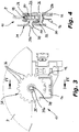
- a first embodiment of an adjusting device for adjusting the position of the window pane of a motor vehicle window lifter comprises, in a manner known per se, a slider 10 that supports a window pane P.
- the slider 10 is intended to be slidably mounted along a guide rail (not shown) which is engaged in a pair of seats 12 formed in a base plate 14 of the slider 10, to allow a window pane P to slide with respect to the window lifter. Sliding of the slider 10 is controlled in a manner known per se through a flexible cable (not shown) associated with a motorized or manually operated displacement unit. In the most common case, the flexible cable is wound on a rotating drum the rotation of which is controlled by a ratio-motor (not shown) which is connected to the structure of the door to which the window lifter is associated, and usually fixed to the aforesaid guide rail or to the door framework.
- the slider 10 also comprises a jaw 16 opposed to the base plate 14 and movably mounted with respect to the latter, which is intended to be arranged on the side facing an outer panel of the motor vehicle door.
- a gap 18 for accommodating the lower edge of the window pane P, or a respective support member thereof, is defined, as it will be more clearly explained below.
- the receiving gap 18 is defined by a substantially U-shaped insert 20 comprising a pair of opposing side walls 22 and 24, first and second respectively, which delimit from opposite sides the gap 18 for inserting the aforesaid portion of the lower bottom portion of the edge of the window pane P.
- the first side wall 22 of the insert 20 is intended to be arranged adjacent to the base plate 14, while the second side wall is intended to be arranged adjacent to the movable jaw 16.
- the insert 20 is made of plastic material such as an elastomeric material, so as to be at least partially flexible and compressible.
- Adjustable clamping means are associated with the base plate 14 and the movable jaw 16 in order to allow their relative distance to be modified, and therefore the distance between the side walls 22 and 24, in order to release or clamp the window pane P inside the gap 18.
- These clamping means comprise a screw member 26 that crosses the base plate 14 at a smooth hole 28 the diameter of which substantially corresponds to the diameter of the screw member 26, until it engages a nut screw 30 formed in a bracket 32 arranged on the side of the movable jaw 16, and interposed between the latter and the gap 18.
- the clamping means also comprise a rotatable member 34 having the shape of a toothed gear wheel 36 provided with wavy teeth, such teeth being intended to be engaged by a tool having a corresponding shape (not shown being known per se) which can be inserted into the door on which the window lifter is mounted, through a so-called "belt opening” and after having possibly removed a door belt weather strip, in a position interposed between the slider 10 and the outer door panel, in order to create a clearance between the slider 10 and the window pane P, to allow the position of the window pane P to be adjusted as desired.
- a threaded element in the form of a screw 38 is associated with a hub central portion 35 of the rotatable member 34, which engages a corresponding hole 40 of the bracket 32.
- the bracket 32 is generally S-shaped in a side view.
- it comprises a first portion 32a in which the nut screw 30 is formed, a second portion 32b in which the hole 40 for engaging the screw 38 is made, and a third portion 32c for connecting the portions 32a and 32b.
- the portions 32a and 32b extend on typically parallel and spaced apart planes, and the axes of the nut screw 30 and the hole 40 are typically parallel and spaced apart.
- a pair of parallel wings 42 extend from the sides of the portion 32b to engage a pair of corresponding seats 44 of the movable jaw 16, the wings 42 and the seats 44 forming mutual engagement formations of the jaw 16 and the bracket 32, in order to ensure a predetermined positioning of the bracket 32 with respect to the jaw 16, even when a clearance exists between the movable jaw 16 on one side, and the base plate 14 on the other side, with respect to the edge of the window pane P.
- the screw 38 is fixed in the hole 40 of the second portion 32b of the bracket 32, typically by interference or riveting, and the threaded stem thereof crosses the movable jaw 16 at a respective hole 46, until it engages a nut screw 35a formed in the hub 35 of the rotatable member 34.
- the screw member 26 is screwed into the nut 30 of the bracket 32 during an initial rough adjustment step, which is carried out upon assembly of the window pane P on the window lifter device, and also the screw 38, which is integral with the portion 32b of the bracket 32, is screwed into the nut screw 35a of the hub 35 of the rotatable member 34.
- the abovementioned tool is operated on the rotatable member 34 to loosen its tightening with respect to the screw 38, thus creating a clearance between the bracket 32 and the jaw 16 or, in other words, between the window pane P, the plate 14 and the jaw 16, as well as between the side walls 22 and 24 of the insert 20 and the window pane P.
- the position of the window pane P can be finely adjusted with respect to the axes X and Z.
- the rotatable member 34 is rotated in the opposite direction by means of the aforesaid tool for tightening it again with respect to the screw 38 and nullifying the clearance between the window pane P and the base plate 14, on one side, and the movable jaw 16, on the other side, in order to lock the window pane P in the new position reached.
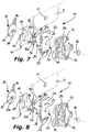
- FIGS 5 to 7 show a second embodiment of an adjusting device for adjusting the position of the window pane of a window lifter of a motor vehicle, according to the invention.
- the same references have been used to indicate parts equal or similar to those of the embodiment previously described. For the sake of clarity and brevity, mostly the parts differing from those of the previous embodiment are only described.
- the window pane P has a through hole 11 made in a portion thereof close to its lower edge, and the insert 20 is conveniently obtained by molding a fairly rigid plastic material, although still partially flexible.
- the two side walls 22 and 24 each have a general thin wall shape, and are mutually connected at a pair of flexible laminar hinges 23 arranged on the side opposite to the window pane P.
- the hole 11 of the window pane P is crossed by the screw member 26 which also engages the respective holes 28 and 29 formed in the plate 14 and in the side wall 22, as well as a hole in the side wall 24.
- the holes 28 and 29 formed in the plate 14 and in the first side wall 22 are smooth and the respective diameters substantially correspond to the diameter of the threaded shank of the screw member 26, while the hole 11 of the window pane P and the hole of the second side wall 24 are substantially larger.
- the clamping means also comprise in this case a rotatable member 34 having the shape of a toothed gear wheel 36 provided with wavy teeth, the teeth of which are intended to be engaged by a tool having a corresponding shape that can be inserted, through a so-called "belt opening", into the door in which the window lifter is mounted and after having possibly removed a door belt weather strip, in a position interposed between the slider 10 and the outer door panel, in order to create a clearance between the slider 10 and the window pane P, to allow the position of the window pane P to be adjusted in a desired manner.
- the screw 38 of this embodiment which extends along an axis substantially parallel and spaced apart with respect to the axes of the screw member 26 and of the nut screw 30, has a stem fixed by interference or riveting in the hub portion 35 of the rotatable member 34, for example at the head thereof, which crosses the jaw 16 and engages a corresponding threaded hole 40, or auxiliary nut screw, of the first portion 32a of the bracket 32.
- a wing 42 extends from the top of the portion 32b of the bracket 32, which is intended to engage a corresponding seat 44 of the movable jaw 16, the wing 42 and the seat 44 forming mutual engagement formations that allow a predetermined positioning of the jaw 16 and of the bracket 32 to be assured.
- FIG. 8 shows a modification of the second embodiment of the invention described above. In the following, only the parts of this modification which are different from the second embodiment are described.
- the screw 38 is fixed at a hole 40 of the portion 32b of the bracket 32, typically by interference or riveting, and the threaded shank of the screw 38, which extends along an axis parallel and spaced apart from the axis of the nut screw 30, is intended to pass through a hole 46 of the jaw 16 to engage a nut screw formed in the hub 35 of the rotatable member 34.
- the side wall 22 of the insert 20 remains substantially stationary with respect to the plate 14, owing to the fact that the diameters of the holes of the plate 14 and of the side wall 22 are substantially the same as the diameter of the shank of the screw member 26. Also the side wall 24 of the insert 20 and the bracket 32, owing to the engagement of the wing 42 in the seat 44, remain substantially stationary with respect to the side wall 22 and the plate 14, whereby the window pane P can undergo only a relative displacement with respect to the insert 20 and the screw member 26.
- Figures 9 and 10 show a third embodiment of an adjusting device for adjusting the position of the window pane of a window lifter of a motor vehicle, according to the invention.
- the same references have been used to indicate parts equal or similar to those of the second embodiment described above. For the sake of clarity and brevity, mostly the parts differing from those of the second embodiment are only described.
- the window pane P still has a through hole 11 made in a portion close to its lower edge, and the insert 20 is conveniently made as described in the second embodiment.
- the screw member 26 crosses an opening 28 of the plate 14, the dimensions of which are substantially wider than the diameter of the shank of the screw member 26, and which has, for example, a square shape.
- a collar 24a is inserted between the screw member 26 and the edge of the hole 11, which extends from the side wall 24 of the insert 20 towards the side wall 22, and which occupies a prevalent part of the space as a result of the aforementioned difference in diameters.
- a pair of T-shaped guide projections 46 extend from the face of the side wall 22 facing the opposite side of the side wall 24, on opposite sides with respect to the screw member 26, each having a main branch from which a pair of auxiliary transverse branches extend.
- the main branch of each projection 46 which is directly connected to the side wall 22, engages a respective slot 48 that extends vertically with respect to the window pane P, that is in the direction Z, such slots 48 being axially aligned with each other.
- each slot 48 has a width, in the X direction, such as to allow a clearance for the respective projection 46.
- a displacement of the window pane P along the directions X and Z in view of carrying out the aforementioned fine adjustment of the position of the window pane P with respect to the slider 10, involves a corresponding dragging of the insert 20 with respect to the plate 14, by virtue of the substantial engagement of the collar 24a of the side wall 24 into the hole 11 of the window pane P.
- the jaw 16 moves substantially integrally with the insert 20, since it is connected to the side wall 24 which is in turn connected in an almost stiff manner with the side wall 22.
- the window pane P after having created a clearance between the window pane P and the plate 14 and the jaw 16, the window pane P can be moved only together with the insert 20, and the movement of the insert 20 is limited in the X and Z directions by the length and width, respectively, of the slots 48, with respect to the size of the main branch of the projections 46, and it may occur within a predetermined range of positions with respect to the base plate 14.
- the transverse branches of the T-shaped projections are then used to prevent an accidental separation of the insert 20 with respect to the plate 14 during the assembly of the slider 10 on the window lifter device together with the window pane P.
- Figures 11 and 12 are shown respective constructive modifications concerning a support appendage 50 of the window pane P, which appendage is suitable for allowing the connection of the window pane with a slider 10 according to the invention.
- the support appendage 50 is intended for use with window panes P without a hole 11, to allow their connection with sliders 10 having the structure described in the second or third embodiment.
- the appendage 50 comprises a lower laminar portion 50a the thickness of which is usually smaller than that of the window pane P, which is adapted for engaging the gap 18 defined between the side walls 22 and 24 of the insert 20 interposed between the plate 14 and the jaw 16, and an upper fork-shaped portion 50b that includes a pair of branches spaced apart from each other by a distance equal to the thickness of the window pane P, to accommodate a lower edge of such a window pane.
- a substantially keyhole shaped recess 52 ( Figure 11 ) or an inverted U-shaped recess 54 ( Figure 12 ), is formed in the portion 50a, which recesses 52 and 54 are open towards the bottom, that is to the side opposite with respect to the portion 50b and the window pane P.
- the recesses 52 and 54 allow the screw member 26 to be accommodated upon insertion of the appendage 50 in the gap 18 in the already mounted condition of the slider 10, typically in the initial assembling step of the window pane P on the window lifter, and the desired positioning of the window pane P to be reached with respect to the slider 10 during the fine adjustment step of its position.
- the screw 26 is in this case preferably supplied already pre-assembled on the slider 10, that is with its threaded stem partially screwed into the nut 30 of the bracket 32, so as to avoid the need for the vehicle manufacturer to couple the screw 26 to the slider 10.
Landscapes
- Window Of Vehicle (AREA)
Claims (11)
- Einstellvorrichtung zum Einstellen der Position einer Fensterscheibe, die mit einem Fahrzeugfensterheber verbunden ist, wobei die Einstellvorrichtung einen Schieber (10) aufweist, der verschiebbar auf einer Führungsschiene des Fensters montierbar ist, wobei der Schieber (10) eine Grundplatte (14) und eine bewegliche Backe (16) gegenüber der Grundplatte (14) aufweist, wobei ein Spalt (18) zur Aufnahme einer unteren Kante der Fensterscheibe (P) oder eines Stützelements (50) derselben zwischen der Grundplatte (14) und der beweglichen Backe (16) definiert ist, und wobei einstellbare Klemmmittel des Schiebers (10) welche dazu ausgelegt sind, eine Änderung des Abstands zwischen der Grundplatte (14) und der beweglichen Backe (16) zu ermöglichen, um die Fensterscheibe (P) oder ein zugehöriges Stützelement (50) in dem Spalt (18) freizugeben oder festzuklemmen, mit der Grundplatte (14) und der beweglichen Backe (16) verbunden sind, wobei die Klemmmittel ein Schraubelement (26), das die Grundplatte (14) und den Spalt (18) durchläuft, wobei das Schraubelement (26) mit einer Hauptschraubenmutter (30) auf der Seite der beweglichen Backe (16) in Eingriff steht, und ein mit der Hauptschraubenmutter (30) verbundenes drehbares Element (34) umfassen, um den Abstand zwischen Letzterem und der beweglichen Backe (16) zu ändern, um einen Zwischenraum zwischen der Grundplatte (14), der beweglichen Backe (16) und der Fensterscheibe (P) oder einem zugehörigen Stützelement (50) einzustellen, dadurch gekennzeichnet, dass die Hauptschraubenmutter (30) an einem Klammerelement (32) ausgebildet ist, das zwischen dem Spalt (18) und der beweglichen Backe (16) angeordnet ist, und dass das drehbare Element (34) mit einem Gewindeelement (38) verbunden ist, das in ein zugehöriges Loch (40) des Klammerelements (32) eingreift, welches in einer von der Hauptschraubenmutter (30) radial beabstandeten Position ausgebildet ist.
- Vorrichtung nach Anspruch 1, dadurch gekennzeichnet, dass das Gewindeelement eine parallel zur Achse der Hauptschraubenmutter (30) und von dieser beabstandet angeordnete Schraube (38) ist, die in einem Loch (40) des Klammerelements (32) befestigt ist und einen Schaft aufweist, der die bewegliche Backe (16) durchläuft und mit einer Hilfsschraubenmutter (35a) in Eingriff steht, die in einem Nabenabschnitt (35) des drehbaren Elements (34) ausgebildet ist.
- Vorrichtung nach Anspruch 1, dadurch gekennzeichnet, dass das Gewindeelement eine parallel zur Achse der Hauptschraubenmutter (30) und von dieser beabstandet angeordnete Schraube (38) ist, die an dem drehbaren Element (34) befestigt ist und einen Schaft aufweist, der die bewegliche Backe (16) durchläuft und mit einer Hilfsschraubenmutter (35b) der Klammer (32) in Eingriff steht.
- Vorrichtung nach einem der Ansprüche 1 bis 3, dadurch gekennzeichnet, dass die Klammer (32) und die bewegliche Backe (16) gegenseitige Eingriffsausbildungen (42, 44) aufweisen, um eine vorbestimmte Positionierung der Klammer (32) in Bezug zur beweglichen Backe (16) selbst bei Vorhandensein des Zwischenraums zwischen der Fensterscheibe (P), der Grundplatte (14) und der beweglichen Backe (16) zu gewährleisten.
- Vorrichtung nach einem der Ansprüche 1 bis 4, dadurch gekennzeichnet, dass die Klammer (32) in einer Seitenansicht im wesentlichen S-förmig ist und einen ersten Abschnitt (32a), der die Hauptschraubenmutter (30) enthält, einen zweiten Abschnitt (32b), der sich in einer Ebene parallel zu und beabstandet von dem ersten Abschnitt (32b) erstreckt, in dem das Loch (40) zum Eingriff mit der Schraube (38) ausgebildet ist, und einen dritten Abschnitt (32c) zwischen dem ersten und dem zweiten Abschnitt (32a, 32b) aufweist.
- Vorrichtung nach einem der Ansprüche 1 bis 5, dadurch gekennzeichnet, dass sie einen Einsatz (20) umfasst, der ein Paar gegenüberliegender Seitenwände (22, 24) aus einem zumindest teilweise flexiblen Material aufweist, um den Spalt (18) zur Aufnahme der Unterkante der Fensterscheibe (P) oder eines damit verbundenen Stützelements (50) auf gegenüberliegenden Seiten zu begrenzen, wobei die erste (22) und die zweite (24) Seitenwand dazu bestimmt sind, benachbart zur Grundplatte (14) bzw. zur beweglichen Backe (16) angeordnet zu werden.
- Vorrichtung nach Anspruch 6, dadurch gekennzeichnet, dass der Einsatz (20) im Wesentlichen U-förmig ist und aus Kunststoffmaterial hergestellt ist.
- Vorrichtung nach Anspruch 6 oder 7, dadurch gekennzeichnet, dass das Schraubelement (26) in ein Loch (28) der Grundplatte (14) und in ein Loch (29) der ersten Seitenwand (22) des Einsatzes (20) eingesetzt ist, wobei die Durchmesser der Löcher (28, 29) im Wesentlichen dem Durchmesser des Schaftes des Schraubelements (26) entsprechen, und dass die Fensterscheibe (P), oder dessen Stützelement (50) eine Öffnung (28) aufweist, die wesentlich größer als der Durchmesser des Schaftes des Schraubelementes (26) ist, wodurch die Fensterscheibe (P) bei Vorhandensein des Zwischenraumes zwischen sich, der Grundplatte (14) und der beweglichen Backe (16) in Bezug zum Schraubelement (26) und zum Einsatz (20) bewegt werden kann.
- Vorrichtung nach Anspruch 6 oder 7, dadurch gekennzeichnet, dass das Schraubelement (26) durch eine Öffnung (28) der Grundplatte (14) eingeführt wird, die eine Größe aufweist, welche wesentlich größer ist als der Durchmesser des Schaftes des Schraubelementes (26), und dass sich ein Kragen (24a) von der zweiten Seitenwand (24) des Einsatzes (20) zur ersten Seitenwand (22) hin erstreckt, wobei der Kragen (24a) dazu bestimmt ist, zwischen einer Öffnung (11, 52) der Fensterscheibe (P) oder ihres Stützelements (50) und dem selben Schraubenelement (26) angeordnet zu werden, wobei die Öffnung wesentlich größer als der Durchmesser des Schafts des Schraubelements (26) ist, wodurch die Fensterscheibe (P) bei Vorhandensein des Zwischenraums zwischen sich, der Grundplatte (14) und der beweglichen Backe (16) zusammen mit dem Einsatz (20) in Bezug zur Grundplatte (14) bewegt werden kann.
- Vorrichtung nach Anspruch 9, dadurch gekennzeichnet, dass die erste Seitenwand (22) Führungselemente (46) aufweist, die dazu bestimmt sind, in hohle Ausbildungen (48) der Grundplatte (14) einzugreifen, um die Bewegung des Einsatzes (20) sowie der beweglichen Backe (16) und der Fensterscheibe (P) oder ihres Stützelements (50) innerhalb eines Bereichs von vorbestimmten Positionen in Bezug zur Grundplatte (14) zu begrenzen.
- Vorrichtung nach einem der Ansprüche 1 bis 10, dadurch gekennzeichnet, dass die Fensterscheibe (P) von einem Ansatz (50) getragen wird, in dem eine durchgehende Ausnehmung (52, 54) ausgebildet ist, die sich zum Schieber (10) hin öffnet und dazu bestimmt ist, mit dem Schraubelement (26) in Eingriff zu kommen, wobei das Schraubelement (26) bereits auf dem Schieber (10) vormontiert ist, wobei sein Gewindeschaft teilweise in die Schraubmutter (30) der Klammer (32) eingeschraubt ist, bevor der Ansatz (50) in den Spalt (18) zur Aufnahme des Schiebers (10) eingeführt wird.
Applications Claiming Priority (1)
| Application Number | Priority Date | Filing Date | Title |
|---|---|---|---|
| IT102017000110189A IT201700110189A1 (it) | 2017-10-02 | 2017-10-02 | Dispositivo di regolazione della posizione del vetro di un alzacristallo di un autoveicolo. |
Publications (2)
| Publication Number | Publication Date |
|---|---|
| EP3461981A1 EP3461981A1 (de) | 2019-04-03 |
| EP3461981B1 true EP3461981B1 (de) | 2020-08-12 |
Family
ID=61024963
Family Applications (1)
| Application Number | Title | Priority Date | Filing Date |
|---|---|---|---|
| EP18000774.2A Active EP3461981B1 (de) | 2017-10-02 | 2018-09-28 | Einstellvorrichtung zum einstellen der position der fensterscheibe eines kraftfahrzeugfensterhebers |
Country Status (2)
| Country | Link |
|---|---|
| EP (1) | EP3461981B1 (de) |
| IT (1) | IT201700110189A1 (de) |
Families Citing this family (3)
| Publication number | Priority date | Publication date | Assignee | Title |
|---|---|---|---|---|
| DE102018200925A1 (de) * | 2018-01-22 | 2019-07-25 | Brose Fahrzeugteile Gmbh & Co. Kommanditgesellschaft, Bamberg | Mitnehmer mit schwenkbarem Klemmteil und Montageverfahren |
| US11162291B2 (en) | 2019-06-05 | 2021-11-02 | Brose Fahrzeugteile Gmbh & Co. Kommanditgesellschaft, Bamberg | Adjustable slider for window regulator |
| CN115071387B (zh) * | 2022-07-21 | 2024-12-03 | 福耀玻璃工业集团股份有限公司 | 托架结构、无框车门及车辆 |
Family Cites Families (2)
| Publication number | Priority date | Publication date | Assignee | Title |
|---|---|---|---|---|
| DE102012102795B4 (de) * | 2012-03-30 | 2013-11-21 | Küster Holding GmbH | Befestigungsvorrichtung zum Befestigen einer Fensterscheibe innerhalb einer Fahrzeugkarosserie eines Kraftfahrzeuges |
| DE202012104557U1 (de) * | 2012-11-23 | 2014-02-27 | Brose Fahrzeugteile Gmbh & Co. Kommanditgesellschaft, Hallstadt | Mitnehmer |
-
2017
- 2017-10-02 IT IT102017000110189A patent/IT201700110189A1/it unknown
-
2018
- 2018-09-28 EP EP18000774.2A patent/EP3461981B1/de active Active
Non-Patent Citations (1)
| Title |
|---|
| None * |
Also Published As
| Publication number | Publication date |
|---|---|
| EP3461981A1 (de) | 2019-04-03 |
| IT201700110189A1 (it) | 2019-04-02 |
Similar Documents
| Publication | Publication Date | Title |
|---|---|---|
| CN111236789B (zh) | 用于无框门的可调节提升器板 | |
| EP3461981A1 (de) | Einstellvorrichtung zum einstellen der position der fensterscheibe eines kraftfahrzeugfensterhebers | |
| DK2829679T3 (en) | Fittings for pressing a sliding frame against a fixed frame | |
| CA2364823C (en) | Casement window with improved tie bar guide and striker | |
| JP7171701B2 (ja) | スライドドア用ガラス板固定装置 | |
| US9481231B2 (en) | Automotive glass channel bracket and method | |
| US20090007494A1 (en) | Adjustable Window Regulator Lifter Plate Assembly For A Vehicle Window | |
| US9160220B2 (en) | Linear actuator particularly for sliding doors and for sliding door or window closure elements in general | |
| EP4013633B1 (de) | Vorrichtung zum halten eines rahmens in einer öffnung, rahmen mit einer solchen vorrichtung, fenster, freizeitfahrzeug mit einem solchen rahmen oder fenster und verfahren zum halten des rahmens oder des fensters in der öffnung | |
| US20020017061A1 (en) | Window-lift device for motor vehicles with a connector means for attaching a window panel to a drive element | |
| US20180312045A1 (en) | Flush glazed device for vehicle door with movable panel, corresponding door and motor vehicle | |
| US8528259B1 (en) | Method of adjusting door glass cross car for frameless window systems | |
| EP2447456B1 (de) | Verfahren zur selbstanpassenden Registrierung der Position der Fensterscheibe einer Kraftfahrzeugtür mit rahmenlosem Fenster, sowie für dieses Verfahren vorgesehene Kraftfahrzeugtür | |
| EP1698752B1 (de) | Ein einstellbares Scharnier für schwere Türe und Fenster | |
| CN101132937A (zh) | 装有遮阳装置的汽车门内部板 | |
| US20050268558A1 (en) | Window regulator slider and vehicle window regulator equipped with a window regulator slider | |
| EP3530854B1 (de) | Verstellvorrichtung zur höhenverstellung einer durch einen fahrzeug-fensterheber gestützten fensterscheibe | |
| US8196349B2 (en) | Lifting window | |
| US20070240283A1 (en) | Hinged for doors or windows | |
| DE102007014098A1 (de) | Bahngesteuerter Kraftfahrzeug-Fensterheber | |
| EP4464862A1 (de) | Scharnier für eine tür oder ein fenster | |
| EP2499317B1 (de) | Tür- oder fensterbremsvorrichtung für eine tür- oder fensteranordnung | |
| EP4665935B1 (de) | Anordnung mit wenigstens einem profil für wenigstens ein abdeckelement und mit diesem wenigstens einem abdeckelement | |
| KR102727669B1 (ko) | 프레임리스 도어 글라스의 캐리어 플레이트 | |
| WO2010012741A1 (en) | Device for adjusting the trim of a chain-type actuator for automating doors or windows |
Legal Events
| Date | Code | Title | Description |
|---|---|---|---|
| PUAI | Public reference made under article 153(3) epc to a published international application that has entered the european phase |
Free format text: ORIGINAL CODE: 0009012 |
|
| STAA | Information on the status of an ep patent application or granted ep patent |
Free format text: STATUS: THE APPLICATION HAS BEEN PUBLISHED |
|
| AK | Designated contracting states |
Kind code of ref document: A1 Designated state(s): AL AT BE BG CH CY CZ DE DK EE ES FI FR GB GR HR HU IE IS IT LI LT LU LV MC MK MT NL NO PL PT RO RS SE SI SK SM TR |
|
| AX | Request for extension of the european patent |
Extension state: BA ME |
|
| RBV | Designated contracting states (corrected) |
Designated state(s): AL AT BE BG CH CY CZ DE DK EE ES FI FR GB GR HR HU IE IS IT LI LT LU LV MC MK MT NL NO PL PT RO RS SE SI SK SM TR |
|
| STAA | Information on the status of an ep patent application or granted ep patent |
Free format text: STATUS: REQUEST FOR EXAMINATION WAS MADE |
|
| 17P | Request for examination filed |
Effective date: 20191111 |
|
| GRAP | Despatch of communication of intention to grant a patent |
Free format text: ORIGINAL CODE: EPIDOSNIGR1 |
|
| STAA | Information on the status of an ep patent application or granted ep patent |
Free format text: STATUS: GRANT OF PATENT IS INTENDED |
|
| RIC1 | Information provided on ipc code assigned before grant |
Ipc: E05F 11/38 20060101AFI20200131BHEP |
|
| INTG | Intention to grant announced |
Effective date: 20200219 |
|
| GRAS | Grant fee paid |
Free format text: ORIGINAL CODE: EPIDOSNIGR3 |
|
| GRAA | (expected) grant |
Free format text: ORIGINAL CODE: 0009210 |
|
| STAA | Information on the status of an ep patent application or granted ep patent |
Free format text: STATUS: THE PATENT HAS BEEN GRANTED |
|
| AK | Designated contracting states |
Kind code of ref document: B1 Designated state(s): AL AT BE BG CH CY CZ DE DK EE ES FI FR GB GR HR HU IE IS IT LI LT LU LV MC MK MT NL NO PL PT RO RS SE SI SK SM TR |
|
| REG | Reference to a national code |
Ref country code: CH Ref legal event code: EP |
|
| REG | Reference to a national code |
Ref country code: IE Ref legal event code: FG4D |
|
| REG | Reference to a national code |
Ref country code: DE Ref legal event code: R096 Ref document number: 602018006738 Country of ref document: DE |
|
| REG | Reference to a national code |
Ref country code: AT Ref legal event code: REF Ref document number: 1301705 Country of ref document: AT Kind code of ref document: T Effective date: 20200915 |
|
| REG | Reference to a national code |
Ref country code: LT Ref legal event code: MG4D |
|
| REG | Reference to a national code |
Ref country code: NL Ref legal event code: MP Effective date: 20200812 |
|
| PG25 | Lapsed in a contracting state [announced via postgrant information from national office to epo] |
Ref country code: BG Free format text: LAPSE BECAUSE OF FAILURE TO SUBMIT A TRANSLATION OF THE DESCRIPTION OR TO PAY THE FEE WITHIN THE PRESCRIBED TIME-LIMIT Effective date: 20201112 Ref country code: LT Free format text: LAPSE BECAUSE OF FAILURE TO SUBMIT A TRANSLATION OF THE DESCRIPTION OR TO PAY THE FEE WITHIN THE PRESCRIBED TIME-LIMIT Effective date: 20200812 Ref country code: HR Free format text: LAPSE BECAUSE OF FAILURE TO SUBMIT A TRANSLATION OF THE DESCRIPTION OR TO PAY THE FEE WITHIN THE PRESCRIBED TIME-LIMIT Effective date: 20200812 Ref country code: NO Free format text: LAPSE BECAUSE OF FAILURE TO SUBMIT A TRANSLATION OF THE DESCRIPTION OR TO PAY THE FEE WITHIN THE PRESCRIBED TIME-LIMIT Effective date: 20201112 Ref country code: SE Free format text: LAPSE BECAUSE OF FAILURE TO SUBMIT A TRANSLATION OF THE DESCRIPTION OR TO PAY THE FEE WITHIN THE PRESCRIBED TIME-LIMIT Effective date: 20200812 Ref country code: GR Free format text: LAPSE BECAUSE OF FAILURE TO SUBMIT A TRANSLATION OF THE DESCRIPTION OR TO PAY THE FEE WITHIN THE PRESCRIBED TIME-LIMIT Effective date: 20201113 Ref country code: FI Free format text: LAPSE BECAUSE OF FAILURE TO SUBMIT A TRANSLATION OF THE DESCRIPTION OR TO PAY THE FEE WITHIN THE PRESCRIBED TIME-LIMIT Effective date: 20200812 |
|
| REG | Reference to a national code |
Ref country code: AT Ref legal event code: MK05 Ref document number: 1301705 Country of ref document: AT Kind code of ref document: T Effective date: 20200812 |
|
| PG25 | Lapsed in a contracting state [announced via postgrant information from national office to epo] |
Ref country code: RS Free format text: LAPSE BECAUSE OF FAILURE TO SUBMIT A TRANSLATION OF THE DESCRIPTION OR TO PAY THE FEE WITHIN THE PRESCRIBED TIME-LIMIT Effective date: 20200812 Ref country code: PL Free format text: LAPSE BECAUSE OF FAILURE TO SUBMIT A TRANSLATION OF THE DESCRIPTION OR TO PAY THE FEE WITHIN THE PRESCRIBED TIME-LIMIT Effective date: 20200812 Ref country code: NL Free format text: LAPSE BECAUSE OF FAILURE TO SUBMIT A TRANSLATION OF THE DESCRIPTION OR TO PAY THE FEE WITHIN THE PRESCRIBED TIME-LIMIT Effective date: 20200812 Ref country code: LV Free format text: LAPSE BECAUSE OF FAILURE TO SUBMIT A TRANSLATION OF THE DESCRIPTION OR TO PAY THE FEE WITHIN THE PRESCRIBED TIME-LIMIT Effective date: 20200812 Ref country code: IS Free format text: LAPSE BECAUSE OF FAILURE TO SUBMIT A TRANSLATION OF THE DESCRIPTION OR TO PAY THE FEE WITHIN THE PRESCRIBED TIME-LIMIT Effective date: 20201212 |
|
| PG25 | Lapsed in a contracting state [announced via postgrant information from national office to epo] |
Ref country code: SM Free format text: LAPSE BECAUSE OF FAILURE TO SUBMIT A TRANSLATION OF THE DESCRIPTION OR TO PAY THE FEE WITHIN THE PRESCRIBED TIME-LIMIT Effective date: 20200812 Ref country code: RO Free format text: LAPSE BECAUSE OF FAILURE TO SUBMIT A TRANSLATION OF THE DESCRIPTION OR TO PAY THE FEE WITHIN THE PRESCRIBED TIME-LIMIT Effective date: 20200812 Ref country code: CZ Free format text: LAPSE BECAUSE OF FAILURE TO SUBMIT A TRANSLATION OF THE DESCRIPTION OR TO PAY THE FEE WITHIN THE PRESCRIBED TIME-LIMIT Effective date: 20200812 Ref country code: DK Free format text: LAPSE BECAUSE OF FAILURE TO SUBMIT A TRANSLATION OF THE DESCRIPTION OR TO PAY THE FEE WITHIN THE PRESCRIBED TIME-LIMIT Effective date: 20200812 Ref country code: EE Free format text: LAPSE BECAUSE OF FAILURE TO SUBMIT A TRANSLATION OF THE DESCRIPTION OR TO PAY THE FEE WITHIN THE PRESCRIBED TIME-LIMIT Effective date: 20200812 |
|
| REG | Reference to a national code |
Ref country code: DE Ref legal event code: R097 Ref document number: 602018006738 Country of ref document: DE |
|
| PG25 | Lapsed in a contracting state [announced via postgrant information from national office to epo] |
Ref country code: MC Free format text: LAPSE BECAUSE OF FAILURE TO SUBMIT A TRANSLATION OF THE DESCRIPTION OR TO PAY THE FEE WITHIN THE PRESCRIBED TIME-LIMIT Effective date: 20200812 Ref country code: ES Free format text: LAPSE BECAUSE OF FAILURE TO SUBMIT A TRANSLATION OF THE DESCRIPTION OR TO PAY THE FEE WITHIN THE PRESCRIBED TIME-LIMIT Effective date: 20200812 Ref country code: AT Free format text: LAPSE BECAUSE OF FAILURE TO SUBMIT A TRANSLATION OF THE DESCRIPTION OR TO PAY THE FEE WITHIN THE PRESCRIBED TIME-LIMIT Effective date: 20200812 Ref country code: AL Free format text: LAPSE BECAUSE OF FAILURE TO SUBMIT A TRANSLATION OF THE DESCRIPTION OR TO PAY THE FEE WITHIN THE PRESCRIBED TIME-LIMIT Effective date: 20200812 |
|
| PLBE | No opposition filed within time limit |
Free format text: ORIGINAL CODE: 0009261 |
|
| REG | Reference to a national code |
Ref country code: BE Ref legal event code: MM Effective date: 20200930 |
|
| STAA | Information on the status of an ep patent application or granted ep patent |
Free format text: STATUS: NO OPPOSITION FILED WITHIN TIME LIMIT |
|
| PG25 | Lapsed in a contracting state [announced via postgrant information from national office to epo] |
Ref country code: LU Free format text: LAPSE BECAUSE OF NON-PAYMENT OF DUE FEES Effective date: 20200928 Ref country code: SK Free format text: LAPSE BECAUSE OF FAILURE TO SUBMIT A TRANSLATION OF THE DESCRIPTION OR TO PAY THE FEE WITHIN THE PRESCRIBED TIME-LIMIT Effective date: 20200812 |
|
| 26N | No opposition filed |
Effective date: 20210514 |
|
| PG25 | Lapsed in a contracting state [announced via postgrant information from national office to epo] |
Ref country code: BE Free format text: LAPSE BECAUSE OF NON-PAYMENT OF DUE FEES Effective date: 20200930 Ref country code: SI Free format text: LAPSE BECAUSE OF FAILURE TO SUBMIT A TRANSLATION OF THE DESCRIPTION OR TO PAY THE FEE WITHIN THE PRESCRIBED TIME-LIMIT Effective date: 20200812 Ref country code: IE Free format text: LAPSE BECAUSE OF NON-PAYMENT OF DUE FEES Effective date: 20200928 |
|
| REG | Reference to a national code |
Ref country code: CH Ref legal event code: PL |
|
| PG25 | Lapsed in a contracting state [announced via postgrant information from national office to epo] |
Ref country code: TR Free format text: LAPSE BECAUSE OF FAILURE TO SUBMIT A TRANSLATION OF THE DESCRIPTION OR TO PAY THE FEE WITHIN THE PRESCRIBED TIME-LIMIT Effective date: 20200812 Ref country code: MT Free format text: LAPSE BECAUSE OF FAILURE TO SUBMIT A TRANSLATION OF THE DESCRIPTION OR TO PAY THE FEE WITHIN THE PRESCRIBED TIME-LIMIT Effective date: 20200812 Ref country code: CY Free format text: LAPSE BECAUSE OF FAILURE TO SUBMIT A TRANSLATION OF THE DESCRIPTION OR TO PAY THE FEE WITHIN THE PRESCRIBED TIME-LIMIT Effective date: 20200812 |
|
| PG25 | Lapsed in a contracting state [announced via postgrant information from national office to epo] |
Ref country code: MK Free format text: LAPSE BECAUSE OF FAILURE TO SUBMIT A TRANSLATION OF THE DESCRIPTION OR TO PAY THE FEE WITHIN THE PRESCRIBED TIME-LIMIT Effective date: 20200812 |
|
| PG25 | Lapsed in a contracting state [announced via postgrant information from national office to epo] |
Ref country code: PT Free format text: LAPSE BECAUSE OF FAILURE TO SUBMIT A TRANSLATION OF THE DESCRIPTION OR TO PAY THE FEE WITHIN THE PRESCRIBED TIME-LIMIT Effective date: 20200812 |
|
| PG25 | Lapsed in a contracting state [announced via postgrant information from national office to epo] |
Ref country code: LI Free format text: LAPSE BECAUSE OF NON-PAYMENT OF DUE FEES Effective date: 20210930 Ref country code: CH Free format text: LAPSE BECAUSE OF NON-PAYMENT OF DUE FEES Effective date: 20210930 |
|
| P01 | Opt-out of the competence of the unified patent court (upc) registered |
Effective date: 20230603 |
|
| PGFP | Annual fee paid to national office [announced via postgrant information from national office to epo] |
Ref country code: DE Payment date: 20250917 Year of fee payment: 8 |
|
| PGFP | Annual fee paid to national office [announced via postgrant information from national office to epo] |
Ref country code: IT Payment date: 20250922 Year of fee payment: 8 |
|
| PGFP | Annual fee paid to national office [announced via postgrant information from national office to epo] |
Ref country code: GB Payment date: 20250919 Year of fee payment: 8 |
|
| PGFP | Annual fee paid to national office [announced via postgrant information from national office to epo] |
Ref country code: FR Payment date: 20250922 Year of fee payment: 8 |