EP3461966B1 - Step or staircase arrangement for sloping areas with different inclinations - Google Patents
Step or staircase arrangement for sloping areas with different inclinations Download PDFInfo
- Publication number
- EP3461966B1 EP3461966B1 EP18196760.5A EP18196760A EP3461966B1 EP 3461966 B1 EP3461966 B1 EP 3461966B1 EP 18196760 A EP18196760 A EP 18196760A EP 3461966 B1 EP3461966 B1 EP 3461966B1
- Authority
- EP
- European Patent Office
- Prior art keywords
- pass
- stair
- opening
- openings
- sloped surface
- Prior art date
- Legal status (The legal status is an assumption and is not a legal conclusion. Google has not performed a legal analysis and makes no representation as to the accuracy of the status listed.)
- Active
Links
- 230000035515 penetration Effects 0.000 claims description 22
- 238000003780 insertion Methods 0.000 claims description 17
- 230000037431 insertion Effects 0.000 claims description 17
- 238000000034 method Methods 0.000 claims description 14
- 229910000831 Steel Inorganic materials 0.000 claims description 10
- 239000010959 steel Substances 0.000 claims description 10
- 238000010276 construction Methods 0.000 description 3
- 238000011161 development Methods 0.000 description 3
- 230000018109 developmental process Effects 0.000 description 3
- 239000004033 plastic Substances 0.000 description 3
- 238000003825 pressing Methods 0.000 description 3
- 210000000078 claw Anatomy 0.000 description 2
- 238000004519 manufacturing process Methods 0.000 description 2
- 230000000149 penetrating effect Effects 0.000 description 2
- 239000011150 reinforced concrete Substances 0.000 description 2
- 230000002787 reinforcement Effects 0.000 description 2
- 239000002689 soil Substances 0.000 description 2
- 239000004575 stone Substances 0.000 description 2
- 230000000007 visual effect Effects 0.000 description 2
- 239000002023 wood Substances 0.000 description 2
- 240000007124 Brassica oleracea Species 0.000 description 1
- 235000003899 Brassica oleracea var acephala Nutrition 0.000 description 1
- 235000012905 Brassica oleracea var viridis Nutrition 0.000 description 1
- 241000196324 Embryophyta Species 0.000 description 1
- 230000006978 adaptation Effects 0.000 description 1
- 229910052782 aluminium Inorganic materials 0.000 description 1
- XAGFODPZIPBFFR-UHFFFAOYSA-N aluminium Chemical compound [Al] XAGFODPZIPBFFR-UHFFFAOYSA-N 0.000 description 1
- 230000000712 assembly Effects 0.000 description 1
- 238000000429 assembly Methods 0.000 description 1
- 230000009194 climbing Effects 0.000 description 1
- 238000001746 injection moulding Methods 0.000 description 1
- 239000000463 material Substances 0.000 description 1
- 229910052751 metal Inorganic materials 0.000 description 1
- 239000002184 metal Substances 0.000 description 1
- 239000000203 mixture Substances 0.000 description 1
- 230000003287 optical effect Effects 0.000 description 1
- 230000001681 protective effect Effects 0.000 description 1
- 230000000284 resting effect Effects 0.000 description 1
Images


Classifications
-
- E—FIXED CONSTRUCTIONS
- E06—DOORS, WINDOWS, SHUTTERS, OR ROLLER BLINDS IN GENERAL; LADDERS
- E06C—LADDERS
- E06C7/00—Component parts, supporting parts, or accessories
- E06C7/42—Ladder feet; Supports therefor
- E06C7/44—Means for mounting ladders on uneven ground
-
- E—FIXED CONSTRUCTIONS
- E04—BUILDING
- E04F—FINISHING WORK ON BUILDINGS, e.g. STAIRS, FLOORS
- E04F11/00—Stairways, ramps, or like structures; Balustrades; Handrails
- E04F11/02—Stairways; Layouts thereof
- E04F11/104—Treads
- E04F11/1041—Treads having means to adjust the height, the depth and/or the slope of the stair steps
-
- E—FIXED CONSTRUCTIONS
- E04—BUILDING
- E04G—SCAFFOLDING; FORMS; SHUTTERING; BUILDING IMPLEMENTS OR AIDS, OR THEIR USE; HANDLING BUILDING MATERIALS ON THE SITE; REPAIRING, BREAKING-UP OR OTHER WORK ON EXISTING BUILDINGS
- E04G27/00—Temporary arrangements for giving access from one level to another for men or vehicles, e.g. steps, ramps
-
- E—FIXED CONSTRUCTIONS
- E04—BUILDING
- E04G—SCAFFOLDING; FORMS; SHUTTERING; BUILDING IMPLEMENTS OR AIDS, OR THEIR USE; HANDLING BUILDING MATERIALS ON THE SITE; REPAIRING, BREAKING-UP OR OTHER WORK ON EXISTING BUILDINGS
- E04G3/00—Scaffolds essentially supported by building constructions, e.g. adjustable in height
- E04G3/24—Scaffolds essentially supported by building constructions, e.g. adjustable in height specially adapted for particular parts of buildings or for buildings of particular shape, e.g. chimney stacks or pylons
- E04G3/26—Scaffolds essentially supported by building constructions, e.g. adjustable in height specially adapted for particular parts of buildings or for buildings of particular shape, e.g. chimney stacks or pylons specially adapted for working on roofs
-
- E—FIXED CONSTRUCTIONS
- E04—BUILDING
- E04F—FINISHING WORK ON BUILDINGS, e.g. STAIRS, FLOORS
- E04F11/00—Stairways, ramps, or like structures; Balustrades; Handrails
- E04F11/02—Stairways; Layouts thereof
- E04F11/104—Treads
- E04F11/112—Treads of metal or with an upper layer of metal
Definitions
- the invention relates to a step or step arrangement for free laying on a slope, according to the preambles of claims 1, 3 and 5 and a method for free laying such a step or step arrangement according to claims 2, 4 and 6. Furthermore, the invention also relates a step or staircase system, in particular a floor-based staircase, consisting of several such step or stair step arrangements according to claim 16.
- the EP 0 753 645 A1 a mobile, freely routable single step in the form of a one-piece, angled element, one leg of which forms a tread plate, and which is provided at least at one end with means for adhering or clawing to the site.
- the means for fixed claws on the site are formed by claws protruding from a free edge of the leg.
- the angle of the tread plate in relation to the slope is determined by the geometry of the legs. In the case of large slopes, it may happen that the tread surface is also undesirably inclined, deviating from an ideal horizontal position.
- a generic step or step arrangement is in DE 93 16 169 U1 described.
- support feet can be telescopically extended to a desired length in order to bring the tread part into a horizontal position on a slope.
- the length of the support feet set in each case is fixed by inserting pins which can pass through aligned holes in the outer tubes and inner tubes.
- the ends of the inner tubes are chamfered to facilitate penetration of the support feet into the floor.
- the depth of penetration is limited by a cross bar that connects the two inner tubes and is fixed on both sides.
- Two diagonal telescopic tubes connect the support feet to a rear edge section of the frame.
- the telescopic guides and the additional crossbar create a complex construction, which is also sensitive to dirt, because dirt can penetrate between the telescopic guides, which can be pushed into one another, and thus prevent or impair a relative movement of the pipes.
- US 2004/255406 A1 discloses a step or stair step arrangement in which first and second limiting elements are provided in openings on the front support feet and are pivotally attached to the step plate. Furthermore, a third limiting element is fastened by pins between the front support feet.
- first and second delimitation elements are provided in openings on the front support feet and are pivotally attached to the step plate.
- a third limiting element is fastened by pins between the front support feet.
- the construction squeezes when the first and second delimitation elements are fastened in openings arranged at a different level to adapt to a changed slope.
- the attachment of the third delimitation element in the openings of the front support feet is time-consuming if the tread or step arrangement is to be adapted to a changed slope slope while maintaining a horizontal orientation of the tread surface.
- the invention is based on the object of a step or step arrangement for free laying on a slope of the entrance to further develop the type mentioned in such a way that it can be adapted to various slopes with simple and inexpensive means. Furthermore, a method for freely laying such a step or stair step arrangement and a step or stair step system, in particular a floor-based staircase, which consists of several such step or step arrangement.
- the invention is based on a step arrangement for free laying on a slope surface, comprising at least one step or stair step body with a step surface intended for entry by at least one foot of a person, and at least two in the use position at the front, from the step surface foot parts protruding downwards and spaced apart from one another in the transverse direction, each of which has a first vertical extension measured from the tread surface, the free ends of at least the front foot parts being provided for at least partially penetrating into the slope surface, at least one in the use position, rear of the tread surface foot part protruding downwards, which, measured from the tread surface, has a second vertical extension, the first vertical extension being larger than the second vertical extension, and wherein in a first front foot part of the front foot parts, a plurality of first ones, each at the bottom Different (vertical) level arranged through openings and in a second front foot part of the front foot parts several second, arranged at different (vertical) level through openings are formed.
- the least two front foot parts form foot parts facing down the slope and the at least one rear foot part forms a foot part facing up the slope.
- At least one rod-shaped delimiting element is provided for optional loose insertion into a specific first through opening of the plurality of first through openings and into a specific second through opening of the plurality of second through openings that through the into the specific first through opening and the certain second passage opening used limiting element, the penetration of the at least two front foot parts into the slope surface is limited to a (vertical) level which corresponds to the level of the limiting element.
- a particularly effective limitation of the penetration of the free ends of the foot parts into the slope surface is achieved in that the at least one rod-shaped delimitation element protrudes laterally out of the passage openings and protrudes laterally beyond the foot parts in question.
- the specific first through opening and the specific second through opening can in particular be aligned through openings, so that the limiting element is then aligned horizontally.
- certain first through opening and the certain second through opening can be through openings which are not aligned with one another, in which case the delimiting element is oriented obliquely with respect to the horizontal.
- the through openings can also be designed in the manner of an elongated hole in order to enable such an oblique alignment of the limiting element.
- steps a) to c) are specified in the order in which they occur in succession.
- the chronological order of steps a) and b) can also be reversed.
- the invention is based on a step arrangement for free laying on a slope surface, comprising at least one step or stair step body with a step surface intended for entry by at least one foot of a person, and at least one front step in the use position, from the step surface foot part protruding downwards, which has a first vertical extent measured from the tread surface, at least two rear foot parts in the use position, protruding downward from the tread surface and spaced apart from one another in the transverse direction, each of which has a second vertical extension measured from the tread surface, the free ends of at least the rear foot parts are provided for at least partial penetration into the slope surface, the first vertical extension being greater than the second vertical extension.
- the second aspect provides that in a first rear foot part of the rear foot parts, a plurality of third through openings arranged at different (vertical) levels and in a second rear foot part of the rear foot parts has a plurality of fourth through openings arranged at different (vertical) levels, and at least one rod-shaped limiting element for optional loose insertion into a specific third through opening of the plurality of third through openings and into a specific fourth through opening of the plurality of fourth Through openings are provided that the penetration of the free ends of the at least two rear foot parts into the slope surface is limited to a (vertical) level, which is the (vertical) level, through the limiting element inserted into the specific third through opening and into the specific fourth through opening corresponds to the delimiting element.
- the specific third through opening and the specific fourth through opening can in particular be aligned through openings, so that the limiting element is then aligned horizontally.
- certain third through opening and the certain fourth through opening may not be aligned through openings, in which case the delimiting element is oriented obliquely with respect to the horizontal.
- steps a) to c) are specified in the order in which they occur in succession.
- the chronological order of steps a) and b) can also be reversed.
- the invention is based on a step arrangement for free laying on a slope surface, comprising at least one step or stair step body with a step surface intended for entry by at least one foot of a person, and with at least two in the use position at the front, from the step surface foot parts protruding downwards, which have a first vertical extent measured from the tread surface, the free ends of the front foot parts being provided for at least partial penetration into the slope surface, at least two rear in the use position, protruding downwards from the tread surface and transversely from one another spaced foot portions, each of which has a second vertical extension measured from the tread surface, the free ends of at least the rear foot portions being provided for at least partial penetration into the slope surface, the first vertical extension being greater than the second kale extension is.
- the third aspect provides that at least on one side of the tread or stair step body, on a rear foot part of the rear foot parts arranged on this one side, a plurality of fifth passage openings arranged on different (vertical) levels and on one side on this side front foot part of the front foot parts, a plurality of sixth through openings arranged at different (vertical) levels is formed, and that at least one rod-shaped limiting element is designed for optional loose insertion in a certain fifth through opening of the plurality of through openings and into a certain sixth through opening of the plurality of sixth through openings is provided such that penetration of the free end of the at least one front foot part and the free end of the through the limiting element inserted into the specific fifth through opening and the certain sixth through opening at least one rear foot part in the slope area is limited to a (vertical) level which corresponds to the (vertical) level of the limiting element.
- the specific fifth through opening and the specific sixth through opening can in particular be aligned through openings, so that the limiting element is then aligned horizontally.
- certain fifth through opening and the certain sixth through opening can be non-aligned through openings, in which case the delimiting element is oriented obliquely with respect to the horizontal.
- the principle of the first aspect which is realized in the front foot parts, is transferred to a front and a rear foot part on at least one side of the tread or stair step body.
- steps a) to c) are specified in the order in which they occur in succession.
- the chronological order of steps a) and b) can also be reversed.
- the limiting element inserted into the specific through openings prevents the free ends of the relevant foot parts of the tread or stairway body from being loaded, e.g. penetrate deeper into the (soft) slope surface by means of the appearance of a person than is specified by the respective vertical level of the boundary element.
- the limiting element can be inserted into certain through openings in such a way that when the step or stair arrangement is positioned on the slope, the step is (almost) horizontally aligned and therefore a person's foot slips or slides off the Tread is prevented.
- “Loose insertion” means that the delimiting element in the unassembled state of the step or stair arrangement is received loosely or with play in the through openings, so that the delimiting element can be easily inserted or inserted into the through openings, while in the assembled state or in the use position, the tread - or stair step arrangement on the slope, the limiting element is held in the through openings by frictional forces, which use in particular the weight forces of the step or stair step arrangement People and / or caused by the longitudinal forces due to the penetration of the free end of the foot parts in the slope area.
- the outer diameter or outer dimensions of the delimiting elements are smaller than the inner diameter or inner dimensions of the through openings.
- the invention can therefore be used on slopes in which the free ends of at least the foot parts can penetrate a little when the tread is loaded in order to fix the tread or stairway body in the slope.
- the cross sections of the ends of the foot parts can be designed, for example, with a relatively small cross section.
- the invention can be implemented with simple means, as only the relevant foot parts are to be provided with through-openings and at least one rod-shaped limiting element is to be provided.
- the through openings are arranged equidistantly on a foot part.
- the at least one rod-shaped delimitation element and the through openings can each have a circular cross section.
- the rod-shaped delimitation element can have a circular cross section and the through openings can have an elongated hole cross section.
- any cross section of the rod-shaped delimitation element and the through openings is conceivable, in particular also a square or rectangular cross section, as long as the at least one
- Limiting element with play or loose can be accommodated in the through openings.
- a particularly inexpensive step arrangement results if the rod-shaped limiting element is formed by a rod of reinforced concrete reinforcement.
- Such poles are widely available commercially and therefore inexpensive.
- the step or stair step body is preferably made of sheet steel or aluminum.
- An execution as an injection molding from plastic is also conceivable.
- the surface of the step surface provided for stepping on is preferably provided with a non-slip pad.
- a non-slip pad can in particular consist of a glued-on film with non-slip properties.
- the tread surface can also be designed as a checker plate.
- the tread surface can also have through-bores with serrated edges, the tines projecting away from the tread surface.
- step or stair step body contains a one-piece sheet steel part or is formed by such a one-piece sheet steel part in which the at least two front foot pieces and the at least one rear foot piece are bent from the tread surface .
- a high degree of rigidity of the tread or stair tread body results if the at least one rear foot part and the front foot parts preferably each have an L-shaped cross section.
- An even higher rigidity of the tread or stair step body can be achieved if, in the position of use, a web part is bent on the side of the tread or stair step body, each of which collides with a front foot part and with a rear foot part in a miter. Then a front foot part and a rear foot part can be supported on a lateral web part via the miter when the tread surface is loaded.
- the web part can be riveted to the rear foot part and / or to the front foot part in the miter.
- the tread surface preferably has a planar extent such that only one foot of a person can appear there.
- the tread surface can also have a greater width when viewed in the transverse direction, so that, for example, a person with both feet can also step onto the tread surface at the same time.
- a tread plate cassette can be provided in the area of the tread surface for inserting a tread plate, the tread plate in the inserted position being arranged above and parallel to the tread surface in the position of use.
- the tread plate cassette is preferably connected to the tread or stair step body, in particular to the tread surface, for example by screwing.
- the tread plate cassette can have at least two and at most three profiles with a U-shaped cross section and a base, such a profile being arranged on one edge of the four edges of the base and a further edge without fixing means for fixing the tread plate in the tread plate cassette.
- the fixing means can have at least one bendable tab which is arranged on the further edge of the bottom of the tread plate cassette or on the edge of the tread surface such that in a first position the at least a tab allows the tread plate to be inserted into the tread plate cassette and the tread plate is fixed within the tread plate cassette in a second position of the at least one tab bent relative to the first position.
- the tread plate can be made of wood, (artificial or natural) stone or plastic, or a mix of materials, depending on the visual requirements.
- the invention also relates to a step or stair system, in particular a floor-based staircase, consisting of a plurality of step or stair step arrangements described above.
- connecting means can be provided, by means of which a plurality of step or stair step arrangements can be connected to one another.
- the connecting means can have at least one connecting profile, of which, viewed in the position of use, at least one first engaging element on a first side and one facing away from the first side second side protrudes at least a second engagement element, wherein the first engagement element engages in a through opening of a first step or step arrangement and the second engagement element engages in a through opening of a second step or step arrangement different from the first step or step arrangement, whereby the first step or stair step arrangement and the second step or stair step arrangement are connected to one another in particular essentially without a viewing gap.
- first engagement element and / or the second engagement element can also be hook-shaped.
- the multiple step or stair step arrangements can then, for example, be arranged laterally and also offset with respect to the vertical level on the slope surface in such a way that their order of the step sequence corresponds to a person climbing the slope.
- the multiple tread arrangements can be arranged in a row one behind the other on the slope surface so that they are in alignment with one another stand.
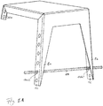
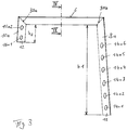
- FIG. 4 Illustrations of a preferred embodiment of a step or stair step arrangement 2 with a step or stair step body 1 for free laying on an inclined slope surface 4 are shown.
- the slope surface 4 takes, for example, a first slope angle ⁇ with respect to a horizontal surface and consists here, for example, of relatively soft soil, so that narrow bodies can easily penetrate the slope surface 4 under pressure.
- the tread or stair step body 1 has a tread 6 provided for entering by, for example, only one foot of a person, as well as here, for example, two front foot parts 8a, 8b, which protrude downward from the tread 6 and are spaced apart in the transverse direction, which measure each have a first vertical extension h1 from the tread surface 6 ( Fig. 3 ).
- rear foot parts 10a, 10b in the use position, which also protrude downward from the tread surface 6, which, measured from the tread surface 6, have a second vertical extension h2, the first vertical extension h1 being greater than the second vertical extension h2 ( Fig. 3 ).
- the free ends 12 of the two front foot parts 8a, 8b and the two rear foot parts 10a, 10b are each provided for at least partially penetrating into the slope surface 4 when the tread surface 6 is loaded. Based on the in Fig. 1 shown situation, the tread or stair step body 1 is still unloaded, so that the free ends 12 of the foot parts 8a, 8b or 10a, 10b are still only on the slope surface 4 but have not yet penetrated into it.
- first front foot part 8a of the front foot parts 8a, 8b there are a plurality of first through openings 14a1 to 14a6, each with a different level position, and in a second front foot part 8b of the front foot parts 8a, 8b second, for example each with the first through openings 14a1 to 14a6 in the transverse direction seen through aligned through opening 14b1 to 14b6 each formed, for example, equidistant.
- the first through openings 14a1 to 14a6 and the second through openings 14b1 to 14b6 differ in each case by a different vertical level on the front foot parts 8a, 8b.
- a rod-shaped limiting element 24 for optional lateral and loose insertion into a specific first through opening 14a1, 14a2, 14a3, 14a4, 14a5 or 14a6 and into a specific second through opening 14b1, 14b2, 14b3, 14b4, 14b5 or 14b6, so that the free ends 12 penetrate through the limiting element 24 of the front foot parts 8a, 8b in the slope surface 4 is limited to a vertical level which corresponds to the vertical level of the limiting element 24 used.
- a slope area with a relatively large slope ⁇ according to Fig. 1A , Figure 1C , Fig.
- the limiting element 24 is inserted, for example, through the second through openings 14a2 and 14b2, seen from below, for example in alignment with one another, the ends of the limiting element 24 projecting a little laterally out of the through openings 14a2, 14b2, for example.
- the proportion of the free ends 12 of the front foot parts 8a, 8b which protrude into the slope surface 4 or are inserted therein is relatively small.
- the slope surface 4 penetrate than is predetermined by the respective vertical level of the limiting element 24.
- the limiting element 24 can be used in certain through openings 14a1, 14a2, 14a3, 14a4, 14a5 or 14a6 or 14b1, 14b2, 14b3, 14b4, 14b5 or 14b6 in such a way that the the step surface 2 positioned step surface 2, the step surface 6 is (almost) aligned horizontally and therefore slipping or sliding of a person's foot is prevented when they put their foot on the step surface 6.
- Figure 1B shows a situation in which the limiting element 24, for example, is not as in FIG Fig. 1A is inserted into through-openings 14a2 and 14b2 which are horizontally aligned with one another, but into through-openings 14a4 and 14b2 which are not exactly aligned with one another.
- the limiting element is then in an angular or oblique position with respect to the horizontal, which is not a result of an adaptation to the shape of the slope surface 4.
- Figure 1C shows a situation in which the limiting element 24, for example, in the first front foot part 8a and the second front foot part 8b as in FIG Fig. 1A is inserted into first and second through openings 14a2, 14b2, each with the same level position.
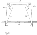
- the two rear foot parts 10a and 10b each have, for example, two second through openings 16a1, 16a2 or 16b1, 16b2, each with a different level, of which a pair 16a1, 16b1 or 16a2, 16b2 are each aligned horizontally with one another.
- a further limiting element 24a is then inserted, for example, through the lowest through openings 16a1 and 16b1.
- the delimiting elements 24, 24a are then in a respective horizontal position.
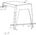
- Fig. 7 shows, for example, the step or stair step arrangement 2 as it is attached to or in a slope surface 4 which, with respect to a horizontal surface, has a second slope angle ⁇ which is smaller than the first slope angle ⁇ .
- the limiting element 24 is inserted, for example, into the second pair of through openings 14a5 and 14b5 in the two front foot parts 8a, 8b when viewed from above. Then the proportion of the free ends 12 of the front foot parts 8a, 8b, which protrude into the slope surface 4 or are inserted therein, is relatively large.
- certain through openings that are in alignment here, for example, are therefore used for loose insertion of the limiting element 24 is selected so that when the free ends 12 penetrate the slope surface 4 under load, this penetration is limited by the limiting element 24 in such a way that the tread surface 6 is oriented approximately horizontally in order to ensure a safe step.
- the rod-shaped limiting element 24 is loosely inserted into certain through openings 14a2, 14b2 in the front foot parts 8a, 8b depending on the inclination of the slope surface 4. Then the tread or stair step body 1 with the inserted limiting element 24 is positioned on the slope surface 4 such that the two front foot parts 8a, 8b face downhill and the two rear foot parts 10a, 10b face uphill.
- the free ends 12 of the front foot parts 8a, 8b and the rear foot parts 10a, 10b are pressed into the slope surface 4 with the foot, for example by part of the weight of the person who is resting on the tread 6, until this enters the through openings 14a2 , 14b2 inserted limiting element 24 rests on the slope surface 4 and thereby further penetration of the ends 12 of the front foot parts 8a, 8b into the slope surface 4 is prevented.
- the rod-shaped limiting element 24 and the through openings 14a, 14b can preferably each have a circular cross section. Any cross-section of the rod-shaped delimitation element 24 and the through openings 14a, 14b is conceivable, in particular also a square or rectangular cross-section. Furthermore, the rod-shaped limiting element 24 is formed here, for example, by a rod of reinforced concrete reinforcement.
- the surface of the step surface 6 intended to be entered can be provided with a non-slip pad 26.
- a non-slip pad 26 can in particular consist of a glued-on film with non-slip properties.
- the tread surface 6 can also have through holes 19 with serrated wheels, the tines protruding from the tread surface 6 and then also representing an anti-slip device ( Fig. 1 ).
- an even better adjustment of the orientation or inclination of the step surface 6 of the step or stair step body 1 can be achieved by third through openings 16a1, 16a2 in a first rear foot part 10a of the rear foot parts 10a, 10b and in a second rear foot part 10b rear foot parts 10a, 10b fourth, through openings 16b1, 16b2, which are aligned with the third through openings, for example in the transverse direction, are formed, the third through openings 16a1, 16a2 and the fourth through openings 16b1, 16b2 being distinguished by a different vertical level on the rear foot parts 10a, 10b differentiate.
- the further delimiting element 24a can then be inserted, for example, through the lowest through openings 16a1 and 16b1. As a result, the delimiting elements 24, 24a are then in a respective horizontal position.
- the depth of penetration of their free ends 12 into the slope surface 4 can be limited and thereby the step surface 6 depending on the inclination of the slope surface 4 in the use position of the step or Stair arrangement 2 ideally be aligned horizontally.
- step or stair step body 1 is formed, as here, by a one-piece sheet steel part in which the front foot parts 8a, 8b and the rear foot parts 10a, 10b are bent from the step surface 6 are, as in particular based on 1 to 5 is easy to imagine.
- the rear foot parts 10a, 10b and the front foot parts 8a, 8b each preferably have an L-shaped cross section.
- a web part 28a, 28b is also laterally folded from the step or stair step body 1, which abuts the front foot parts 8a, 8b and the rear foot parts 10a, 10b in a miter 30a, 30b, 30c, 30d. Then, when the tread surface 6 is loaded, the two front foot parts 8a, 8b and the two rear foot parts 10a, 10b can each be supported on the lateral web parts via the miters 30a, 30b, 30c, 30d.
- the tread surface 6 preferably has a planar extent such that only one foot of a person can occur there.
- the tread 6 can also have a larger width in the manner of a step in the transverse direction, so that, for example, a person with both feet can also step on the tread 6 at the same time.
- the invention also relates to a step or stair system, in particular a floor or slope-bound staircase consisting of a plurality of step or stair step arrangements 2 described above, which are attached to the slope surface 4 in such a way that the slope surface 4 can be walked on as a whole.
- the plurality of tread or stair step arrangements 2 can then, for example, laterally and also with respect to the vertical level on the slope surface 4 can be arranged offset such that their arrangement corresponds to the order in which a person steps up the slope surface 4.
- the plurality of steps or steps 2 can be arranged on the slope 4 in the manner of steps in one Row must be arranged one behind the other so that they are in alignment with each other.
- a locally or continuously curved course of the floor-bound or slope-bound staircase can also be provided, depending on in which the individual step or stair step arrangements 2 are arranged relative to one another on the slope surface 4.
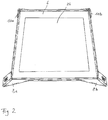
- a tread plate cassette 18, for example made of sheet steel, can be fastened on the tread surface 6 for inserting a tread plate 20, for example by screwing, the tread plate 20 being arranged in the inserted position above and parallel to the tread surface 6.
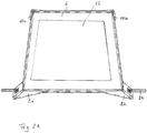
- the tread plate cassette 18, which is made, for example, in one piece from sheet steel, can have a rectangular or square cross section and, for example, have three adjoining profiles 22a, 22b, 22c each with a U-shaped cross section and a base 25 on the edge ( Fig. 9 ), wherein such a profile 22 is arranged on one edge of the bottom 25 and the fourth edge is provided without such a profile, but has fixing means 23 for fixing the tread plate 20 inserted into the profiles 22a to 22c in the tread plate cassette 18 .
- the fixing means can have bendable (sheet metal) tabs 23 arranged on the fourth edge of the bottom 25 of the tread plate cassette 18 such that the tread plate 20 can be inserted into the tread plate cassette 18 in a first position of the tab, such as Fig. 8 and Fig. 9 show, and in a second, compared to the first position here, for example, upwardly bent position of the tabs 23, the tread plate 20 is fixed within the tread plate cassette 18.
- the tabs 23 can in turn be made in one piece with the tread plate cassette 18 from sheet steel.
- the tread plate 20 can be made of wood, stone or plastic, for example, in order to produce a desired visual impression.
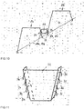
- releasable connecting means can be provided in particular, by means of which a plurality of step or stair step arrangements 2a, 2b can be connected to one another, as in FIG 10 and 11 emerges.
- the connecting means can be formed, for example, by a trapezoidal connecting profile 32, of which, seen in the position of use, first engagement elements, for example in the form of first hooks 34, and second engagement elements, for example in the form of second hooks 36, on a second side pointing away from the first side stick out ( Fig. 11 ).
- connection profile 32 is provided for each of the front and rear foot parts 8a, 10a and 8b, 10b, the first hooks 34 of the then two connection profiles 32, for example, in through openings of the rear foot parts 10a, 10b of a first step or stair step arrangement 2a and the second hooks 36 in through openings of the front foot parts 8a, 8b of a second step or step arrangement 2a different from the first step or step arrangement 2a Intervene in step arrangement 2b.
- the trapezoidal connection profile 32 here, for example, is preferably designed such that the first step or stair step arrangement 2a and the second step or stair step arrangement 2b are connected to one another in particular essentially without a viewing gap.
- the hooks 34, 36 of the connecting profile 32 are then disengaged from the through openings of the foot parts 8a, 8b or 10a, 10b in order to release the step or stair step arrangements 2a, 2b.
Landscapes
- Engineering & Computer Science (AREA)
- Architecture (AREA)
- Mechanical Engineering (AREA)
- Civil Engineering (AREA)
- Structural Engineering (AREA)
- Steps, Ramps, And Handrails (AREA)
- Tires In General (AREA)
Description
Die Erfindung betrifft eine Tritt- oder Treppenstufenanordnung zum freien Verlegen an einer Hangfläche, gemäß den Oberbegriffen der Patentansprüche 1, 3 und 5 sowie Verfahren zum freien Verlegen einer solchen Tritt- oder Treppenstufenanordnung gemäß den Ansprüchen 2, 4 und 6. Weiterhin betrifft die Erfindung auch ein Tritt- oder Treppenstufensystem, insbesondere eine bodengebundene Treppe, bestehend aus mehreren solchen Tritt- oder Treppenstufenanordnungen gemäß Patentanspruch 16.The invention relates to a step or step arrangement for free laying on a slope, according to the preambles of
Das Gehen, Stehen und Arbeiten von Menschen an steilen Hangflächen, insbesondere an solchen mit großer Neigung ist beschwerlich und gefährlich. Dies gilt umso mehr wenn Lasten getragen oder im Stillstand Werkzeuge gehandhabt werden müssen, beispielsweise zum Bearbeiten von Boden und Pflanzen oder bei Bauarbeiten. Dabei muss jeweils ein wesentlicher Teil der aufgewendeten Kraft für den Erhalt der Körperbalance aufgewendet werden. Trotzdem lassen sich oft Stürze oder ein Abgleiten hangabwärts nicht vermeiden. Diese Schwierigkeiten können sich bei rutschiger oder nasser Hangfläche soweit steigern, dass ein Stehen, Gehen oder Arbeiten an der Hangfläche nur noch mit Hilfsmitteln zu bewerkstelligen ist.Walking, standing and working on steep slopes, especially on steep inclines, is difficult and dangerous. This applies all the more when loads have to be carried or tools have to be handled when the machine is at a standstill, e.g. for working on soil and plants or during construction work. In doing so, a significant part of the force applied must be used to maintain body balance. Nevertheless, falls or slides down the slope are often unavoidable. These difficulties can increase to such an extent on slippery or wet slope surfaces that standing, walking or working on the slope surface can only be accomplished with aids.
Um diese Probleme zu lösen, schlägt die
Eine gatttungsgemäße Tritt- oder Treppenstufenanordnung wird in
Der Erfindung liegt demgegenüber die Aufgabe zugrunde, eine Tritt- oder Treppenstufenanordnung zum freien Verlegen an einer Hangfläche der eingangs erwähnten Art derart weiter zu bilden, dass sie mit einfachen und kostengünstigen Mittel an verschiedene Hangneigungen anpassbar ist. Weiterhin soll auch ein Verfahren zum freien Verlegen einer solchen Tritt- oder Treppenstufenanordnung sowie ein Tritt- oder Treppenstufensystem, insbesondere eine bodengebundene Treppe angegeben werden, welche aus mehreren solchen Tritt- oder Treppenstufenanordnungen besteht.In contrast, the invention is based on the object of a step or step arrangement for free laying on a slope of the entrance to further develop the type mentioned in such a way that it can be adapted to various slopes with simple and inexpensive means. Furthermore, a method for freely laying such a step or stair step arrangement and a step or stair step system, in particular a floor-based staircase, which consists of several such step or step arrangement.
Diese Aufgabe wird durch die Merkmale der nebengeordneten Patentansprüche 1, 2, 3, 4, 5, 6 und 16 gelöst.This object is achieved by the features of the
Die Erfindung geht gemäß einem ersten Aspekt aus von einer Trittstufenanordnung zum freien Verlegen an einer Hangfläche, aufweisend wenigstens einen Tritt- oder Treppenstufenkörper mit einer zum Betreten durch wenigstens einen Fuß einer Person vorgesehenen Trittfläche, sowie mit wenigstens zwei in Gebrauchslage vorderen, von der Trittfläche nach unten weg ragenden und voneinander in Querrichtung beabstandeten Fußteilen, welche gemessen von der Trittfläche jeweils eine erste vertikale Erstreckung aufweisen, wobei die freien Enden wenigstens der vorderen Fußteile zum wenigstens teilweise Eindringen in die Hangfläche vorgesehen sind, wenigstens einem in Gebrauchslage hinteren, von der Trittfläche nach unten weg ragenden Fußteil, welches gemessen von der Trittfläche eine zweite vertikale Erstreckung aufweist, wobei die erste vertikale Erstreckung größer als die zweite vertikale Erstreckung ist, und wobei in einem ersten vorderen Fußteil der vorderen Fußteile mehrere erste, auf jeweils unterschiedlichem (vertikalem) Niveau angeordnete Durchgangsöffnungen und in einem zweiten vorderen Fußteil der vorderen Fußteile mehrere zweite, auf jeweils unterschiedlichem (vertikalem) Niveau angeordnete Durchgangsöffnungen ausgebildet sind.According to a first aspect, the invention is based on a step arrangement for free laying on a slope surface, comprising at least one step or stair step body with a step surface intended for entry by at least one foot of a person, and at least two in the use position at the front, from the step surface foot parts protruding downwards and spaced apart from one another in the transverse direction, each of which has a first vertical extension measured from the tread surface, the free ends of at least the front foot parts being provided for at least partially penetrating into the slope surface, at least one in the use position, rear of the tread surface foot part protruding downwards, which, measured from the tread surface, has a second vertical extension, the first vertical extension being larger than the second vertical extension, and wherein in a first front foot part of the front foot parts, a plurality of first ones, each at the bottom Different (vertical) level arranged through openings and in a second front foot part of the front foot parts several second, arranged at different (vertical) level through openings are formed.
In Gebrauchslage, d.h. wenn die Trittstufenanordnung an der Hangfläche angebracht ist, bilden dann die wenigsten zwei vorderen Fußteile hangabwärts gewandte Fußteile und das wenigstens eine hintere Fußteil ein hangaufwärts gewandtes Fußteil.In the position of use, ie when the step arrangement is attached to the slope surface, then the least two front foot parts form foot parts facing down the slope and the at least one rear foot part forms a foot part facing up the slope.
Erfindungsgemäß ist bei dem ersten Aspekt vorgesehen, dass wenigstens ein stangenförmiges Begrenzungselement derart zum wahlweisen losen Einsetzen in eine bestimmte erste Durchgangsöffnung der mehreren ersten Durchgangsöffnungen und in eine bestimmte zweite Durchgangsöffnung der mehreren zweiten Durchgangsöffnungen vorgesehen ist, dass durch das in die bestimmte erste Durchgangsöffnung und die bestimmte zweite Durchgangsöffnung eingesetzte Begrenzungselement ein Eindringen der wenigstens zwei vorderen Fußteile in die Hangfläche auf ein (vertikales) Niveau begrenzt wird, welches dem Niveau des Begrenzungselements entspricht.According to the invention, it is provided in the first aspect that at least one rod-shaped delimiting element is provided for optional loose insertion into a specific first through opening of the plurality of first through openings and into a specific second through opening of the plurality of second through openings that through the into the specific first through opening and the certain second passage opening used limiting element, the penetration of the at least two front foot parts into the slope surface is limited to a (vertical) level which corresponds to the level of the limiting element.
Erfindungsgemäß wird eine besonders wirksame Begrenzung des Eindringens der freien Enden der Fußteile in die Hangfläche dadurch erzielt, dass das wenigstens eine stangenförmige Begrenzungselement jeweils seitlich ein Stück weit aus den Durchgangsöffnungen herausragt und seitlich über die betreffenden Fußteile übersteht.According to the invention, a particularly effective limitation of the penetration of the free ends of the foot parts into the slope surface is achieved in that the at least one rod-shaped delimitation element protrudes laterally out of the passage openings and protrudes laterally beyond the foot parts in question.
Dabei können die bestimmte erste Durchgangsöffnung und die bestimmte zweite Durchgangsöffnung insbesondere miteinander fluchtende Durchgangsöffnungen sein, so dass dann das Begrenzungselement horizontal ausgerichtet ist. Alternativ können bestimmte erste Durchgangsöffnung und die bestimmte zweite Durchgangsöffnung nicht miteinander fluchtende Durchgangsöffnungen sein, wobei dann das Begrenzungselement in Bezug zur Horizontalen schräg ausgerichtet ist. Insbesondere können die Durchgangsöffnungen auch langlochartig ausgebildet sein, um eine solche schräge Ausrichtung des Begrenzungselements zu ermöglichen.The specific first through opening and the specific second through opening can in particular be aligned through openings, so that the limiting element is then aligned horizontally. Alternatively, certain first through opening and the certain second through opening can be through openings which are not aligned with one another, in which case the delimiting element is oriented obliquely with respect to the horizontal. In particular, the through openings can also be designed in the manner of an elongated hole in order to enable such an oblique alignment of the limiting element.
Ein Verfahren zum freien Verlegen einer solchen Trittstufenanordnung gemäß dem ersten Aspekt an einer Hangfläche ist dann gekennzeichnet durch wenigstens die folgenden Verfahrensschritte:
- a) Loses Einsetzen des stangenförmigen Begrenzungselements in die bestimmte erste Durchgangsöffnung und in die bestimmte zweite Durchgangsöffnung abhängig von der Neigung der Hangfläche, derart, dass das wenigstens eine stangenförmige Begrenzungselement jeweils seitlich ein Stück weit aus den Durchgangsöffnungen herausragt und seitlich über die betreffenden Fußteile übersteht,
- b) Positionieren des Tritt- oder Treppenstufenkörpers an der Hangfläche derart, dass die wenigstens zwei vorderen Fußteile hangabwärts gewandt sind und das wenigstens eine hintere Fußteil hangaufwärts gewandt ist,
- c) Eindrücken der freien Enden wenigstens der vorderen Fußteile in die Hangfläche bis das in die bestimmte erste Durchgangsöffnung und in die bestimmte zweite Durchgangsöffnung eingesetzte Begrenzungselement auf der Hangfläche aufliegt und dadurch ein weiteres Eindringen der freien Enden zumindest der vorderen Fußteile in die Hangfläche verhindert wird.
- a) loose insertion of the rod-shaped limiting element into the specific first through opening and into the specific second through opening depending on the inclination of the slope, such that the at least one rod-shaped delimitation element protrudes laterally from the through openings and protrudes laterally beyond the relevant foot parts,
- b) positioning the step or stair step body on the slope surface such that the at least two front foot parts face down the slope and the at least one rear foot part faces up the slope,
- c) Pressing the free ends of at least the front foot parts into the slope surface until the limiting element inserted into the specific first through opening and into the specific second through opening rests on the slope surface, thereby preventing further penetration of the free ends of at least the front foot parts into the slope surface.
Die Verfahrensschritte a) bis c) sind in der Reihenfolge angegeben, in welcher sie zeitlich hintereinander erfolgen. Dabei kann die zeitliche Reihenfolge der Schritte a) und b) aber auch vertauscht sein.The process steps a) to c) are specified in the order in which they occur in succession. The chronological order of steps a) and b) can also be reversed.
Die Erfindung geht gemäß einem zweiten Aspekt aus von einer Trittstufenanordnung zum freien Verlegen an einer Hangfläche, aufweisend wenigstens einen Tritt- oder Treppenstufenkörper mit einer zum Betreten durch wenigstens einen Fuß einer Person vorgesehenen Trittfläche, sowie mit wenigstens einem in Gebrauchslage vorderen, von der Trittfläche nach unten weg ragenden Fußteil, welches gemessen von der Trittfläche eine erste vertikale Erstreckung aufweist, wenigstens zwei in Gebrauchslage hinteren, von der Trittfläche nach unten weg ragenden und voneinander in Querrichtung beabstandeten Fußteilen, welche gemessen von der Trittfläche jeweils eine zweite vertikale Erstreckung aufweisen, wobei die freien Enden wenigstens der hinteren Fußteile zum wenigstens teilweise Eindringen in die Hangfläche vorgesehen sind, wobei die erste vertikale Erstreckung größer als die zweite vertikale Erstreckung ist.According to a second aspect, the invention is based on a step arrangement for free laying on a slope surface, comprising at least one step or stair step body with a step surface intended for entry by at least one foot of a person, and at least one front step in the use position, from the step surface foot part protruding downwards, which has a first vertical extent measured from the tread surface, at least two rear foot parts in the use position, protruding downward from the tread surface and spaced apart from one another in the transverse direction, each of which has a second vertical extension measured from the tread surface, the free ends of at least the rear foot parts are provided for at least partial penetration into the slope surface, the first vertical extension being greater than the second vertical extension.
Erfindungsgemäß ist bei dem zweiten Aspekt vorgesehen, dass in einem ersten hinteren Fußteil der hinteren Fußteile mehrere dritte, auf jeweils unterschiedlichem (vertikalen) Niveau angeordnete Durchgangsöffnung und in einem zweiten hinteren Fußteil der hinteren Fußteile mehrere vierte, auf jeweils unterschiedlichem (vertikalen) Niveau angeordnete Durchgangsöffnungen ausgebildet sind, und wenigstens ein stangenförmiges Begrenzungselement derart zum wahlweisen losen Einsetzen in eine bestimmte dritte Durchgangsöffnung der mehreren dritten Durchgangsöffnungen und in eine bestimmte vierte Durchgangsöffnung der mehreren vierten Durchgangsöffnungen vorgesehen ist, dass durch das in die bestimmte dritte Durchgangsöffnung und in das in die bestimmte vierte Durchgangsöffnung eingesetzte Begrenzungselement ein Eindringen der freien Enden der wenigstens zwei hinteren Fußteile in die Hangfläche auf ein (vertikales) Niveau begrenzt wird, welches dem (vertikalen) Niveau des Begrenzungselements entspricht.According to the invention, the second aspect provides that in a first rear foot part of the rear foot parts, a plurality of third through openings arranged at different (vertical) levels and in a second rear foot part of the rear foot parts has a plurality of fourth through openings arranged at different (vertical) levels, and at least one rod-shaped limiting element for optional loose insertion into a specific third through opening of the plurality of third through openings and into a specific fourth through opening of the plurality of fourth Through openings are provided that the penetration of the free ends of the at least two rear foot parts into the slope surface is limited to a (vertical) level, which is the (vertical) level, through the limiting element inserted into the specific third through opening and into the specific fourth through opening corresponds to the delimiting element.
Dabei können die bestimmte dritte Durchgangsöffnung und die bestimmte vierte Durchgangsöffnung insbesondere miteinander fluchtende Durchgangsöffnungen sein, so dass dann das Begrenzungselement horizontal ausgerichtet ist. Alternativ können bestimmte dritte Durchgangsöffnung und die bestimmte vierte Durchgangsöffnung nicht miteinander fluchtende Durchgangsöffnungen sein, wobei dann das Begrenzungselement in Bezug zur Horizontalen schräg ausgerichtet ist.The specific third through opening and the specific fourth through opening can in particular be aligned through openings, so that the limiting element is then aligned horizontally. Alternatively, certain third through opening and the certain fourth through opening may not be aligned through openings, in which case the delimiting element is oriented obliquely with respect to the horizontal.
Bei dem zweiten Aspekt der Erfindung wird folglich das in den vorderen Fußteilen verwirklichte Prinzip des ersten Aspekts auf die hinteren Fußteile übertragen.In the second aspect of the invention, the principle of the first aspect implemented in the front foot parts is therefore applied to the rear foot parts.
Ein Verfahren zum freien Verlegen einer Trittstufenanordnung gemäß dem zweiten Aspekt an einer Hangfläche ist dann gekennzeichnet durch wenigstens die folgenden Verfahrensschritte:
- a) Loses Einsetzen des stangenförmigen Begrenzungselements in die bestimmte dritte Durchgangsöffnung und in die bestimmte vierte Durchgangsöffnung abhängig von der Neigung der Hangfläche,
- b) Positionieren des Tritt- oder Treppenstufenkörpers an der Hangfläche derart, dass das wenigstens eine vordere Fußteil hangabwärts gewandt ist und die wenigstens zwei hinteren Fußteil hangaufwärts gewandt sind,
- c) Eindrücken der freien Enden wenigstens der hinteren Fußteile in die Hangfläche bis das in die bestimmte dritte Durchgangsöffnung und in die bestimmte vierte Durchgangsöffnung eingesetzte Begrenzungselement auf der Hangfläche aufliegt und dadurch ein weiteres Eindringen der freien Enden zumindest der hinteren Fußteile in die Hangfläche verhindert wird.
- a) loose insertion of the rod-shaped limiting element into the specific third through opening and into the specific fourth through opening depending on the inclination of the slope surface,
- b) positioning the step or stair step body on the slope surface such that the at least one front foot part faces down the slope and the at least two rear foot parts face up the slope,
- c) Pressing the free ends of at least the rear foot parts into the slope surface until the limiting element inserted into the specific third through opening and into the specific fourth through opening rests on the slope surface and thereby further penetration of the free ends of at least the rear foot parts into the slope surface is prevented.
Die Verfahrensschritte a) bis c) sind in der Reihenfolge angegeben, in welcher sie zeitlich hintereinander erfolgen. Dabei kann die zeitliche Reihenfolge der Schritte a) und b) aber auch vertauscht sein.The process steps a) to c) are specified in the order in which they occur in succession. The chronological order of steps a) and b) can also be reversed.
Die Erfindung geht gemäß einem dritten Aspekt aus von einer Trittstufenanordnung zum freien Verlegen an einer Hangfläche, aufweisend wenigstens einen Tritt- oder Treppenstufenkörper mit einer zum Betreten durch wenigstens einen Fuß einer Person vorgesehenen Trittfläche, sowie mit wenigstens zwei in Gebrauchslage vorderen, von der Trittfläche nach unten weg ragenden Fußteilen, welche gemessen von der Trittfläche eine erste vertikale Erstreckung aufweisen, wobei die freien Enden der vorderen Fußteile zum wenigstens teilweise Eindringen in die Hangfläche vorgesehen sind, wenigstens zwei in Gebrauchslage hinteren, von der Trittfläche nach unten weg ragenden und voneinander in Querrichtung beabstandeten Fußteilen, welche gemessen von der Trittfläche jeweils eine zweite vertikale Erstreckung aufweisen, wobei die freien Enden wenigstens der hinteren Fußteile zum wenigstens teilweise Eindringen in die Hangfläche vorgesehen sind, wobei die erste vertikale Erstreckung größer als die zweite vertikale Erstreckung ist.According to a third aspect, the invention is based on a step arrangement for free laying on a slope surface, comprising at least one step or stair step body with a step surface intended for entry by at least one foot of a person, and with at least two in the use position at the front, from the step surface foot parts protruding downwards, which have a first vertical extent measured from the tread surface, the free ends of the front foot parts being provided for at least partial penetration into the slope surface, at least two rear in the use position, protruding downwards from the tread surface and transversely from one another spaced foot portions, each of which has a second vertical extension measured from the tread surface, the free ends of at least the rear foot portions being provided for at least partial penetration into the slope surface, the first vertical extension being greater than the second kale extension is.
Erfindungsgemäß ist bei dem dritten Aspekt vorgesehen, dass wenigstens auf einer Seite des Tritt- oder Treppenstufenkörpers an einem auf dieser einen Seite angeordneten hinteren Fußteil der hinteren Fußteile mehrere fünfte, auf jeweils unterschiedlichem (vertikalen) Niveau angeordnete Durchgangsöffnungen und an einem auf dieser einen Seite angeordneten vorderen Fußteil der vorderen Fußteile mehrere sechste, auf jeweils unterschiedlichem (vertikalen) Niveau angeordnete Durchgangsöffnungen ausgebildet ist, und dass wenigstens ein stangenförmiges Begrenzungselement derart zum wahlweisen losen Einsetzen in eine bestimmte fünfte Durchgangsöffnung der mehrere Durchgangsöffnungen und in eine bestimmte sechste Durchgangsöffnung der mehrere sechsten Durchgangsöffnungen vorgesehen ist, dass durch das in die bestimmte fünfte Durchgangsöffnung und die bestimmte sechste Durchgangsöffnung eingesetzte Begrenzungselement ein Eindringen des freien Endes des wenigstens einen vorderen Fußteils und des freien Endes des wenigstens einen hinteren Fußteils in die Hangfläche auf ein (vertikales) Niveau begrenzt wird, welches dem (vertikalen) Niveau des Begrenzungselements entspricht.According to the invention, the third aspect provides that at least on one side of the tread or stair step body, on a rear foot part of the rear foot parts arranged on this one side, a plurality of fifth passage openings arranged on different (vertical) levels and on one side on this side front foot part of the front foot parts, a plurality of sixth through openings arranged at different (vertical) levels is formed, and that at least one rod-shaped limiting element is designed for optional loose insertion in a certain fifth through opening of the plurality of through openings and into a certain sixth through opening of the plurality of sixth through openings is provided such that penetration of the free end of the at least one front foot part and the free end of the through the limiting element inserted into the specific fifth through opening and the certain sixth through opening at least one rear foot part in the slope area is limited to a (vertical) level which corresponds to the (vertical) level of the limiting element.
Dabei können die bestimmte fünfte Durchgangsöffnung und die bestimmte sechste Durchgangsöffnung insbesondere miteinander fluchtende Durchgangsöffnungen sein, so dass dann das Begrenzungselement horizontal ausgerichtet ist. Alternativ können bestimmte fünfte Durchgangsöffnung und die bestimmte sechste Durchgangsöffnung nicht miteinander fluchtende Durchgangsöffnungen sein, wobei dann das Begrenzungselement in Bezug zur Horizontalen schräg ausgerichtet ist.The specific fifth through opening and the specific sixth through opening can in particular be aligned through openings, so that the limiting element is then aligned horizontally. Alternatively, certain fifth through opening and the certain sixth through opening can be non-aligned through openings, in which case the delimiting element is oriented obliquely with respect to the horizontal.
Bei dem dritten Aspekt der Erfindung wird folglich das in den vorderen Fußteilen verwirklichte Prinzip des ersten Aspekts auf ein vorderes und ein hinteres Fußteil auf wenigstens einer Seite des Tritt- oder Treppenstufenkörpers übertragen.In the third aspect of the invention, the principle of the first aspect, which is realized in the front foot parts, is transferred to a front and a rear foot part on at least one side of the tread or stair step body.
Ein Verfahren zum freien Verlegen einer Trittstufenanordnung gemäß dem dritten Aspekt an einer Hangfläche ist dann gekennzeichnet durch wenigstens die folgenden Verfahrensschritte:
- a) Loses Einsetzen des stangenförmigen Begrenzungselements in die bestimmte fünfte Durchgangsöffnung und in die bestimmte sechste Durchgangsöffnung abhängig von der Neigung der Hangfläche,
- b) Positionieren des Tritt- oder Treppenstufenkörpers an der Hangfläche derart, dass die wenigstens zwei vorderen Fußteil hangabwärts gewandt und die wenigstens zwei hinteren Fußteil hangaufwärts gewandt sind,
- c) Eindrücken des freien Endes wenigstens des auf der einen Seite des Tritt-oder Treppenstufenkörpers angeordneten vorderen Fußteils und des freien Endes wenigstens des auf der einen Seite des Tritt- oder Treppenstufenkörpers angeordneten hinteren Fußteils in die Hangfläche bis das in die bestimmte fünfte Durchgangsöffnung und in die bestimmte sechste Durchgangsöffnung eingesetzte Begrenzungselement auf der Hangfläche aufliegt und dadurch ein weiteres Eindringen des freien Endes wenigstens des auf der einen Seite des Tritt- oder Treppenstufenkörpers angeordneten vorderen Fußteils und des freien Endes wenigstens des auf der einen Seite des Tritt- oder Treppenstufenkörpers angeordneten hinteren Fußteils in die Hangfläche verhindert wird.
- a) loose insertion of the rod-shaped limiting element into the specific fifth through opening and into the specific sixth through opening depending on the inclination of the slope surface,
- b) positioning the step or stair step body on the slope surface such that the at least two front foot parts face down the slope and the at least two rear foot parts face up the slope,
- c) pressing in the free end of at least the front foot part arranged on one side of the step or stair step body and the free end End of at least the rear foot part arranged on one side of the step or stair step body into the slope surface until the limiting element inserted into the specific fifth through opening and into the specific sixth through opening rests on the slope surface and thereby further penetration of the free end of at least one on the one Side of the tread or stair step body arranged front foot part and the free end of at least the rear foot part arranged on one side of the tread or stair step body in the slope area is prevented.
Die Verfahrensschritte a) bis c) sind in der Reihenfolge angegeben, in welcher sie zeitlich hintereinander erfolgen. Dabei kann die zeitliche Reihenfolge der Schritte a) und b) aber auch vertauscht sein.The process steps a) to c) are specified in the order in which they occur in succession. The chronological order of steps a) and b) can also be reversed.
Folglich verhindert das in die bestimmten Durchgangsöffnungen eingesetzte Begrenzungselement, dass die freien Enden der betreffenden Fußteile des Tritt-oder Treppenstufenkörpers bei Belastung, z.B. mittels Auftritt einer Person tiefer in die (weiche) Hangfläche eindringen, als dies durch das jeweilige vertikale Niveau des Begrenzungselements vorgegeben ist. Damit kann abhängig von der jeweiligen Neigung der Hangfläche das Begrenzungselement in bestimmte Durchgangsöffnungen derart eingesetzt werden, dass bei der dann an der Hangfläche positionierten Tritt- oder Treppenstufenanordnung die Trittfläche (nahezu) horizontal ausgerichtet ist und deshalb ein Abrutschen oder Abgleiten des Fußes einer Person von der Trittfläche verhindert wird.As a result, the limiting element inserted into the specific through openings prevents the free ends of the relevant foot parts of the tread or stairway body from being loaded, e.g. penetrate deeper into the (soft) slope surface by means of the appearance of a person than is specified by the respective vertical level of the boundary element. Depending on the inclination of the slope, the limiting element can be inserted into certain through openings in such a way that when the step or stair arrangement is positioned on the slope, the step is (almost) horizontally aligned and therefore a person's foot slips or slides off the Tread is prevented.
"Loses Einsetzen" bedeutet, dass das Begrenzungselement im nicht montierten Zustand der Tritt- oder Treppenstufenanordnung lose oder spielbehaftet in den Durchgangsöffnungen aufgenommen ist, so dass das Begrenzungselement leicht in die Durchgangsöffnungen eingeschoben oder eingesetzt werden kann, während im montierten Zustand oder in Gebrauchslage der Tritt- oder Treppenstufenanordnung an der Hangfläche das Begrenzungselement durch Reibungskräfte in den Durchgangsöffnungen gehalten ist, welche insbesondere von Gewichtskräften der die Tritt- oder Treppenstufenanordnung benutzenden Personen und/oder durch die von den Längskräften aufgrund des Eindringens der freien Ende der Fußteile in die Hangfläche hervorgerufen werden. Insbesondere sind die Außendurchmesser oder Außenmaße der Begrenzungselemente kleiner als die Innendurchmesser oder Innenmaße der Durchgangsöffnungen."Loose insertion" means that the delimiting element in the unassembled state of the step or stair arrangement is received loosely or with play in the through openings, so that the delimiting element can be easily inserted or inserted into the through openings, while in the assembled state or in the use position, the tread - or stair step arrangement on the slope, the limiting element is held in the through openings by frictional forces, which use in particular the weight forces of the step or stair step arrangement People and / or caused by the longitudinal forces due to the penetration of the free end of the foot parts in the slope area. In particular, the outer diameter or outer dimensions of the delimiting elements are smaller than the inner diameter or inner dimensions of the through openings.
Die Erfindung ist daher an Hangflächen einsetzbar, in welche die freien Enden wenigstens der Fußteile bei Belastung der Trittfläche ein Stück weit eindringen können, um den Tritt- oder Treppenstufenkörper in der Hangfläche zu fixieren. Hierzu können die Querschnitte der Enden der Fußteile beispielsweise mit relativ kleinem Querschnitt ausgeführt sein.The invention can therefore be used on slopes in which the free ends of at least the foot parts can penetrate a little when the tread is loaded in order to fix the tread or stairway body in the slope. For this purpose, the cross sections of the ends of the foot parts can be designed, for example, with a relatively small cross section.
Die Erfindung ist mit einfachen Mitteln realisierbar, als lediglich die betreffenden Fußteile mit Durchgangsöffnungen zu versehen sind und wenigstens ein stangenförmiges Begrenzungselements vorzusehen ist.The invention can be implemented with simple means, as only the relevant foot parts are to be provided with through-openings and at least one rod-shaped limiting element is to be provided.
Insbesondere sind die Durchgangsöffnungen an einem Fußteil äquidistant angeordnet.In particular, the through openings are arranged equidistantly on a foot part.
Durch die in den Unteransprüchen aufgeführten Maßnahmen sind vorteilhafte Weiterbildungen und Verbesserungen der in den unabhängigen Ansprüchen angegebenen Erfindung möglich.Advantageous further developments and improvements of the invention specified in the independent claims are possible through the measures listed in the subclaims.
Gemäß einer Weiterbildung können das wenigstens eine stangenförmige Begrenzungselement und die Durchgangsöffnungen jeweils einen kreisförmigen Querschnitt aufweisen. Alternativ kann das stangenförmige Begrenzungselement einen kreisförmigen Querschnitt und die Durchgangsöffnungen einen Langlochquerschnitt aufweisen. Denkbar ist aber jeder beliebige Querschnitt des stangenförmigen Begrenzungselements und der Durchgangsöffnungen, insbesondere auch ein quadratischer oder rechteckförmiger Querschnitt, solange das wenigstens eineAccording to a further development, the at least one rod-shaped delimitation element and the through openings can each have a circular cross section. Alternatively, the rod-shaped delimitation element can have a circular cross section and the through openings can have an elongated hole cross section. However, any cross section of the rod-shaped delimitation element and the through openings is conceivable, in particular also a square or rectangular cross section, as long as the at least one
Begrenzungselement spielbehaftet oder lose in den Durchgangsöffnungen aufgenommen werden kann.Limiting element with play or loose can be accommodated in the through openings.
Eine besonders kostengünstige Trittstufenanordnung ergibt sich, wenn das stangenförmige Begrenzungselement durch eine Stange einer Stahlbetonbewehrung gebildet wird. Solche Stangen sind im Handel weit verbreitet und daher kostengünstig.A particularly inexpensive step arrangement results if the rod-shaped limiting element is formed by a rod of reinforced concrete reinforcement. Such poles are widely available commercially and therefore inexpensive.
Bevorzugt ist der Tritt- oder Treppenstufenkörper aus Stahlblech oder aus Aluminium gefertigt. Denkbar ist auch eine Ausführung als Spritzgussformling aus Kunststoff.The step or stair step body is preferably made of sheet steel or aluminum. An execution as an injection molding from plastic is also conceivable.
Bevorzugt ist die zum Betreten vorgesehene Oberfläche der Trittfläche mit einer rutschfesten Auflage versehen. Eine solche rutschfeste Auflage kann insbesondere aus einer aufgeklebten Folie mit rutschfesten Eigenschaften bestehen. Alternativ oder zusätzlich kann die Trittfläche auch als Riffelblech ausgeführt sein. Alternativ oder zusätzlich kann die Trittfläche auch Durchgangsbohrungen mit gezackten Rändern aufweisen, wobei die Zacken von der Trittfläche wegragen.The surface of the step surface provided for stepping on is preferably provided with a non-slip pad. Such a non-slip pad can in particular consist of a glued-on film with non-slip properties. Alternatively or additionally, the tread surface can also be designed as a checker plate. As an alternative or in addition, the tread surface can also have through-bores with serrated edges, the tines projecting away from the tread surface.
Eine besonders kostengünstige Herstellung der Tritt- oder Treppenstufenanordnung ergibt sich auch, wenn der Tritt- oder Treppenstufenkörper ein einstückiges Stahlblechteil beinhaltet oder durch ein solches einstückiges Stahlblechteil gebildet wird, bei welchem die wenigstens zwei vorderen Fußteile und das wenigstens eine hinteren Fußteil von der Trittfläche abgekantet sind.A particularly cost-effective production of the step or stair step arrangement also results if the step or stair step body contains a one-piece sheet steel part or is formed by such a one-piece sheet steel part in which the at least two front foot pieces and the at least one rear foot piece are bent from the tread surface .
Eine hohe Steifigkeit des Tritt- oder Treppenstufenkörpers ergibt sich, wenn das wenigstens eine hintere Fußteil und die vorderen Fußteile bevorzugt jeweils einen L-fömigen Querschnitt aufweisen.A high degree of rigidity of the tread or stair tread body results if the at least one rear foot part and the front foot parts preferably each have an L-shaped cross section.
Eine noch höhere Steifigkeit des Tritt- oder Treppenstufenkörpers kann erzielt werden, wenn in Gebrauchslage gesehen von dem Tritt- oder Treppenstufenkörper jeweils seitlich ein Stegteil abgekantet ist, welches jeweils mit einem vorderen Fußteil und mit einem hinteren Fußteil in einer Gehrung zusammenstößt. Dann können sich bei Belastung der Trittfläche jeweils ein vorderes Fußteil und ein hinteres Fußteil an einem seitlichen Stegteil über die Gehrung abstützen. Zusätzlich kann das Stegteil mit dem hinteren Fußteil und/oder mit dem vorderen Fußteil jeweils in der Gehrung vernietet sein.An even higher rigidity of the tread or stair step body can be achieved if, in the position of use, a web part is bent on the side of the tread or stair step body, each of which collides with a front foot part and with a rear foot part in a miter. Then a front foot part and a rear foot part can be supported on a lateral web part via the miter when the tread surface is loaded. In addition, the web part can be riveted to the rear foot part and / or to the front foot part in the miter.
Bevorzugt weist die Trittfläche eine flächige Ausdehnung auf, dass lediglich ein Fuß einer Person dort auftreten kann. Alternativ kann die Trittfläche aber auch nach Art einer Treppenstufe in Querrichtung gesehen eine größere Breite aufweisen, so dass beispielsweise auch eine Person mit beiden Füßen die Trittfläche gleichzeitig betreten kann.The tread surface preferably has a planar extent such that only one foot of a person can appear there. Alternatively, the tread surface can also have a greater width when viewed in the transverse direction, so that, for example, a person with both feet can also step onto the tread surface at the same time.
Aus optischen Gründen kann im Bereich der Trittfläche eine Trittplatten-Kassette zum Einschieben einer Trittplatte vorgesehen sein, wobei die Trittplatte im eingeschobenen Zustand in Gebrauchslage oberhalb und parallel zur Trittfläche angeordnet ist. Dabei ist die Trittplatten-Kassette bevorzugt mit dem Tritt- oder Treppenstufenkörper, insbesondere mit der Trittfläche verbunden, beispielsweise durch Verschraubung.For optical reasons, a tread plate cassette can be provided in the area of the tread surface for inserting a tread plate, the tread plate in the inserted position being arranged above and parallel to the tread surface in the position of use. The tread plate cassette is preferably connected to the tread or stair step body, in particular to the tread surface, for example by screwing.
Dabei kann die Trittplatten-Kassette wenigstens zwei und höchstens drei Profile mit U-förmigem Querschnitt und einen Boden aufweisen, wobei jeweils ein solches Profil an einem Rand der vier Ränder des Bodens angeordnet ist und ein weiterer ohne Profil ausgeführter Rand Fixierungsmittel zum Fixieren der Trittplatte in der Trittplatten-Kassette aufweist.The tread plate cassette can have at least two and at most three profiles with a U-shaped cross section and a base, such a profile being arranged on one edge of the four edges of the base and a further edge without fixing means for fixing the tread plate in the tread plate cassette.
Dabei können die Fixierungsmittel wenigstens eine an dem weiteren Rand des Bodens der Trittplatten-Kassette oder am Rand der Trittfläche angeordnete derart biegbare Lasche aufweisen, dass in einer ersten Lage der wenigstens einen Lasche ein Einschieben der Trittplatte in die Trittplatten-Kassette möglich und in einer zweiten, gegenüber der ersten Lage gebogenen Lage der wenigstens einen Lasche die Trittplatte innerhalb der Trittplatten-Kassette fixiert ist.In this case, the fixing means can have at least one bendable tab which is arranged on the further edge of the bottom of the tread plate cassette or on the edge of the tread surface such that in a first position the at least a tab allows the tread plate to be inserted into the tread plate cassette and the tread plate is fixed within the tread plate cassette in a second position of the at least one tab bent relative to the first position.
Die Trittplatte kann aus Holz, (Kunst- oder Natur-)Stein oder Kunststoff bestehen, oder auch aus einem Materialmix, je nach optischer Anforderung.The tread plate can be made of wood, (artificial or natural) stone or plastic, or a mix of materials, depending on the visual requirements.
Die Erfindung betrifft auch eine beliebige Kombination des ersten Aspekts, des zweiten Aspekts und des dritten Aspekts, d.h., dass
- a) in bestimmte Durchgangsöffnungen der vorderen Fußteile und/oder in bestimmte Durchgangsöffnungen der hinteren Fußteile (jeweils) ein Begrenzungselement eingesetzt ist, und/oder dass
- b) auf der einen Seite des Tritt- oder Treppenstufenkörpers in eine bestimmte Durchgangsöffnung des einen vorderen Fußteils und in eine bestimmte Durchgangsöffnung des einen hinteren Fußteils und/oder dass auf der anderen Seite des Tritt- oder Treppenstufenkörpers in eine bestimmte Durchgangsöffnung des anderen vorderen Fußteils und in eine bestimmte Durchgangsöffnung des anderen hinteren Fußteils (jeweils) ein Begrenzungselement eingesetzt ist.
- a) a limiting element is inserted into certain through openings of the front foot parts and / or into certain through openings of the rear foot parts, and / or that
- b) on one side of the tread or stair step body into a certain through opening of the one front foot part and into a certain through opening of the one rear foot part and / or that on the other side of the tread or stair step body into a certain through opening of the other front foot part and a limiting element is inserted (in each case) into a certain through opening of the other rear foot part.
Die Erfindung betrifft auch Tritt- oder Treppenstufensystem, insbesondere eine bodengebundene Treppe, bestehend aus mehreren oben beschriebenen Tritt-oder Treppenstufenstufenanordnungen.The invention also relates to a step or stair system, in particular a floor-based staircase, consisting of a plurality of step or stair step arrangements described above.
Dabei können Verbindungsmittel vorgesehen sein, durch welche mehrere Tritt-oder Treppenstufenanordnungen miteinander verbindbar sind.In this case, connecting means can be provided, by means of which a plurality of step or stair step arrangements can be connected to one another.
Die Verbindungsmittel können wenigstens ein Verbindungsprofil aufweisen, von welchem in Gebrauchslage gesehen auf einer ersten Seite wenigstens ein erstes Eingriffselement und auf einer von der ersten Seite weg weisenden zweiten Seite wenigstens ein zweites Eingriffselement weg ragt, wobei das erste Eingriffselement in eine Durchgangsöffnung einer ersten Tritt- oder Treppenstufenanordnung und das zweite Eingriffselement in eine Durchgangsöffnung einer zweiten, von der ersten Tritt- oder Treppenstufenanordnung verschiedenen Tritt- oder Treppenstufenanordnung eingreift, wodurch die erste Tritt- oder Treppenstufenanordnung und die zweite Tritt- oder Treppenstufenanordnung insbesondere im Wesentlichen ohne Sichtspalt miteinander verbunden sind.The connecting means can have at least one connecting profile, of which, viewed in the position of use, at least one first engaging element on a first side and one facing away from the first side second side protrudes at least a second engagement element, wherein the first engagement element engages in a through opening of a first step or step arrangement and the second engagement element engages in a through opening of a second step or step arrangement different from the first step or step arrangement, whereby the first step or stair step arrangement and the second step or stair step arrangement are connected to one another in particular essentially without a viewing gap.
Insbesondere können auch das erste Eingriffselement und/oder das zweite Eingriffselement hakenförmig ausgebildet sein.In particular, the first engagement element and / or the second engagement element can also be hook-shaped.
Insbesondere wenn die Trittfläche eine flächige Ausdehnung derart aufweist, dass lediglich ein Fuß einer Person dort auftreten kann, können die mehreren Tritt- oder Treppenstufenanordnungen dann beispielsweise seitlich und auch bezogen auf das vertikale Niveau an der Hangfläche derart versetzt angeordnet werden, dass ihre Anordnung der Trittreihenfolge einer Person entspricht, welche die Hangfläche hinaufsteigt.In particular, if the step surface has a planar extent such that only one foot of a person can appear there, the multiple step or stair step arrangements can then, for example, be arranged laterally and also offset with respect to the vertical level on the slope surface in such a way that their order of the step sequence corresponds to a person climbing the slope.
Alternativ, insbesondere wenn die Trittfläche nach Art einer Treppenstufe in Querrichtung gesehen eine größere Breite aufweist, so dass eine Person die Trittfläche mit beiden Füßen betreten kann, können die mehreren Trittstufenanordnungen an der Hangfläche in einer Reihe hintereinander angeordnet werden, so dass sie in Flucht zueinander stehen.Alternatively, especially if the tread has a larger width in the manner of a stair tread seen in the transverse direction so that a person can step onto the tread with both feet, the multiple tread arrangements can be arranged in a row one behind the other on the slope surface so that they are in alignment with one another stand.
Vorteilhafte Weiterbildungen der Erfindung ergeben sich aus den Schutzansprüchen, der Beschreibung und den Zeichnungen. Die in der Beschreibungseinleitung genannten Vorteile von Merkmalen und von Kombinationen mehrerer Merkmale sind lediglich beispielhaft und können alternativ oder kumulativ zur Wirkung kommen, ohne dass die Vorteile zwingend von erfindungsgemäßen Ausführungsformen erzielt werden müssen.Advantageous developments of the invention result from the protective claims, the description and the drawings. The advantages of features and combinations of several features mentioned in the introduction to the description are only examples and can alternatively or cumulatively be effective without the advantages necessarily having to be achieved by embodiments according to the invention.
Weitere Merkmale sind den Zeichnungen - insbesondere den dargestellten Geometrien und den relativen Abmessungen mehrerer Bauteile zueinander sowie deren relativer Anordnung und Wirkverbindung - zu entnehmen. Die Kombination von Merkmalen unterschiedlicher Ausführungsformen der Erfindung oder von Merkmalen unterschiedlicher Schutzansprüche ist ebenfalls abweichend von den gewählten Rückbeziehungen der Schutzansprüche möglich und wird hiermit angeregt. Dies betrifft auch solche Merkmale, die in separaten Zeichnungen dargestellt sind oder bei deren Beschreibung genannt werden. Diese Merkmale können auch mit Merkmalen unterschiedlicher Patentansprüche kombiniert werden. Ebenso können in den Schutzansprüchen aufgeführte Merkmale für weitere Ausführungsformen der Erfindung entfallen.Further features can be found in the drawings - in particular the geometries shown and the relative dimensions of a plurality of components to one another and their relative arrangement and operative connection. The combination of features of different embodiments of the invention or of features of different protection claims is also possible, deviating from the selected back relationships of the protection claims, and is hereby suggested. This also applies to those features which are shown in separate drawings or mentioned in the description. These features can also be combined with features of different claims. Likewise, features listed in the protection claims can be omitted for further embodiments of the invention.
Identische bzw. gleich wirkende Bauteile und Baugruppen sind in unterschiedlichen Ausführungsformen jeweils mit denselben Bezugszahlen bezeichnet.In different embodiments, identical or equivalent components and assemblies are each identified by the same reference numbers.
In der Zeichnung zeigt
- Fig. 1
- eine perspektivische Ansicht eines Tritt- oder Treppenstufenkörpers einer Tritt- oder Treppenstufenanordnung gemäß einer bevorzugten Ausführungsform der Erfindung;
- Fig. 1A
- die Tritt- oder Treppenstufenanordnung von
Fig. 1 mit in miteinander fluchtende Durchgangsöffnungen der vorderen Fußteile eingesetztem (horizontalen) Begrenzungselement; - Fig. 1B
- die Tritt- oder Treppenstufenanordnung von
Fig. 1 mit in nicht miteinander fluchtende Durchgangsöffnungen der vorderen Fußteile eingesetztem (schräg angeordnetem) Begrenzungselement; - Fig. 1C
- die Tritt- oder Treppenstufenanordnung von
Fig. 1 mit in jeweils miteinander fluchtende Durchgangsöffnungen der vorderen und hinteren Fußteile eingesetzten (horizontalen) Begrenzungselementen; - Fig. 2
- eine Draufsicht auf den Tritt- oder Treppenstufenkörper von
Fig.1 ; - Fig. 2A
- eine Draufsicht auf die Tritt- oder Treppenanordnung von
Fig.1A oderFig.1B ; - Fig. 2B
- eine Draufsicht auf die Tritt- oder Treppenstufenanordnung von
Fig.1C ; - Fig. 3
- eine Seitenansicht des Tritt- oder Treppenstufenkörpers von
Fig.1 ; - Fig.4
- eine Schnittdarstellung entlang der Linie IV-IV von
Fig.3 ; - Fig.5
- eine Vorderansicht eines Tritt- oder Treppenstufenkörpers mit einem eingesetzten Begrenzungselement;
- Fig.6
- den Tritt- oder Treppenstufenkörper von
Fig.5 mit eingesetztem Begrenzungselement in Gebrauchslage an einer ersten Hangfläche mit größerer Hangneigung α; - Fig.7
- den Tritt- oder Treppenstufenkörper von
Fig.5 mit eingesetztem Begrenzungselement in Gebrauchslage an einer zweiten Hangfläche mit geringerer Hangneigung β; - Fig.8
- eine Vorderansicht eines Tritt- oder Treppenstufenkörpers gemäß einer weiteren Ausführungsform mit einer zusätzlichen Trittplatten-Kassette mit eingeschobener, aber noch nicht fixierter Trittplatte;
- Fig. 9
- eine Einzeldarstellung der Trittplatten-Kassette von
Fig.8 ; - Fig.10
- eine Seitenansicht von zwei durch Verbindungsprofile miteinander verbundenen Tritt- oder Treppenstufenanordnungen;
- Fig. 11
- eine perspektivische Einzeldarstellung eines Verbindungsprofils von
Fig. 10 .
- Fig. 1
- a perspective view of a step or step body of a step or step arrangement according to a preferred embodiment of the invention;
- Fig. 1A
- the arrangement of steps or steps from
Fig. 1 with (horizontal) limiting element inserted into aligned openings of the front foot parts; - Figure 1B
- the arrangement of steps or steps from
Fig. 1 with in through openings of the front foot parts inserted (obliquely arranged) limiting element; - Figure 1C
- the arrangement of steps or steps from
Fig. 1 with (horizontal) limiting elements inserted in through openings of the front and rear foot parts that are aligned with one another; - Fig. 2
- a plan view of the tread or stair body of
Fig. 1 ; - Figure 2A
- a plan view of the step or stair arrangement of
Fig.1A orFig.1B ; - Figure 2B
- a plan view of the step or step arrangement of
Fig.1C ; - Fig. 3
- a side view of the step or stair body of
Fig. 1 ; - Fig. 4
- a sectional view taken along the line IV-IV of
Fig. 3 ; - Fig. 5
- a front view of a tread or stair step body with an inserted limiting element;
- Fig. 6
- the step or stair step body of
Fig. 5 with inserted limiting element in the use position on a first slope surface with a greater slope α ; - Fig. 7
- the step or stair step body of
Fig. 5 with inserted limiting element in the position of use on a second slope with a lower slope β ; - Fig. 8
- a front view of a step or stair body according to another Embodiment with an additional tread plate cassette with an inserted but not yet fixed tread plate;
- Fig. 9
- a single view of the step plate cassette from
Fig. 8 ; - Fig. 10
- a side view of two tread or staircase arrangements interconnected by connecting profiles;
- Fig. 11
- a detailed perspective view of a connection profile of
Fig. 10 .
In
Der Tritt- oder Treppenstufenkörper 1 weist eine zum Betreten durch hier beispielsweise nur einen Fuß einer Person vorgesehene Trittfläche 6, sowie hier beispielsweise zwei in Gebrauchslage vordere, von der Trittfläche 6 nach unten weg ragende und voneinander in Querrichtung beabstandete Fußteile 8a, 8b, welche gemessen von der Trittfläche 6 jeweils eine erste vertikale Erstreckung h1 aufweisen (
Weiterhin sind beispielsweise zwei in Gebrauchslage hintere, von der Trittfläche 6 ebenfalls nach unten weg ragende Fußteile 10a, 10b vorhanden, welche gemessen von der Trittfläche 6 eine zweite vertikale Erstreckung h2 aufweisen, wobei die erste vertikale Erstreckung h1 größer als die zweite vertikale Erstreckung h2 ist (
In der Gebrauchslage von
Die freien Enden 12 der beiden vorderen Fußteile 8a, 8b und der beiden hinteren Fußteile 10a, 10b sind jeweils zum wenigstens teilweise Eindringen in die Hangfläche 4 vorgesehen, wenn die Trittfläche 6 belastet wird. Anhand der in
Dabei sind in einem ersten vorderen Fußteil 8a der vorderen Fußteile 8a, 8b mehrere erste Durchgangsöffnungen 14a1 bis 14a6 mit jeweils unterschiedlicher Niveaulage und in einem zweiten vorderen Fußteil 8b der vorderen Fußteile 8a, 8b zweite, beispielsweise jeweils mit den ersten Durchgangsöffnungen 14a1 bis 14a6 in Querrichtung gesehen fluchtende Durchgangsöffnung 14b1 bis 14b6 jeweils beispielsweise äquidistant ausgebildet.In this case, in a first
Die erste Durchgangsöffnungen 14a1 bis 14a6 und die zweiten Durchgangsöffnungen 14b1 bis 14b6 unterscheiden sich durch ein jeweils anderes vertikales Niveau an den vorderen Fußteilen 8a, 8b.The first through openings 14a1 to 14a6 and the second through openings 14b1 to 14b6 differ in each case by a different vertical level on the
Wie insbesondere
Folglich verhindert das in die hier beispielsweise in die Durchgangsöffnungen 14a2, 14b2 quer eingesetzte Begrenzungselement 24, dass die freien Enden 12 der vorderen Fußteile 8a, 8b des Tritt- oder Treppenstufenkörpers bei Belastung, z.B. mittels Auftritt einer Person tiefer in die (lose oder weiche) Hangfläche 4 eindringen, als dies durch das jeweilige vertikale Niveau des Begrenzungselements 24 vorgegeben ist. Damit kann abhängig von der jeweiligen Neigung der Hangfläche 4 das Begrenzungselement 24 in bestimmte Durchgangsöffnungen 14a1, 14a2, 14a3, 14a4, 14a5 oder 14a6 bzw. 14b1, 14b2, 14b3, 14b4, 14b5 oder 14b6 wahlweise derart eingesetzt werden, dass bei der dann an der Hangfläche 4 positionierten Trittstufenanordnung 2 die Trittfläche 6 (nahezu) horizontal ausgerichtet ist und deshalb ein Abrutschen oder Abgleiten des Fußes einer Person verhindert wird, wenn sie den Fuß auf die Trittfläche 6 setzt.Consequently, the limiting
Zum freien Verlegen der Trittstufenanordnung 2 an der Hangfläche 4 wird daher mit Bezug auf
Schließlich werden die freien Enden 12 der vorderen Fußteile 8a, 8b und der hinteren Fußteile 10a, 10b beispielsweise durch einen Teil der Gewichtskraft der Person, welcher auf der Trittfläche 6 lastet, mit dem Fuß in die Hangfläche 4 eingedrückt, bis das in die Durchgangsöffnungen 14a2, 14b2 eingesetzte Begrenzungselement 24 auf der Hangfläche 4 aufliegt und dadurch ein weiteres Eindringen der Enden 12 der vorderen Fußteile 8a, 8b in die Hangfläche 4 verhindert wird.Finally, the free ends 12 of the
Bevorzugt können das stangenförmige Begrenzungselement 24 und die Durchgangsöffnungen 14a, 14b jeweils einen kreisförmigen Querschnitt aufweisen. Denkbar ist aber jeder beliebige Querschnitt des stangenförmigen Begrenzungselements 24 und der Durchgangsöffnungen 14a, 14b, insbesondere auch ein quadratischer oder rechteckförmiger Querschnitt. Weiterhin wird hier das stangenförmige Begrenzungselement 24 beispielsweise durch eine Stange einer Stahlbetonbewehrung gebildet.The rod-shaped limiting
Zusätzlich kann die zum Betreten vorgesehene Oberfläche der Trittfläche 6 mit einer rutschfesten Auflage 26 versehen sein. Eine solche rutschfeste Auflage 26 kann insbesondere aus einer aufgeklebten Folie mit rutschfesten Eigenschaften bestehen. Alternativ oder zusätzlich kann die Trittfläche 6 auch Durchgangsbohrungen 19 mit gezackten Rädern aufweisen, wobei die Zacken von der Trittfläche 6 wegragen und dann ebenfalls eine Rutschsicherung darstellen (
Gemäß einer weiteren, in
Dann kann sowohl für die vorderen als auch für die hinteren Fußteile 8a, 8b bzw. 10a, 10b die Eindringtiefe von deren freien Enden 12 in die Hangfläche 4 begrenzt und dadurch die Trittfläche 6 abhängig von der Neigung der Hangfläche 4 in Gebrauchslage der Tritt- oder Treppenstufenanordnung 2 ideal horizontal ausgerichtet werden.Then, both for the front and for the
Eine besonders kostengünstige Herstellung der Tritt- oder Treppenstufenanordnung 2 ergibt sich auch, wenn der Tritt- oder Treppenstufenkörper 1 wie hier durch ein einstückiges Stahlblechteil gebildet wird, bei welchem die vorderen Fußteile 8a, 8b und die hinteren Fußteile 10a, 10b von der Trittfläche 6 abgekantet sind, wie insbesondere anhand von
Weiterhin weisen die hinteren Fußteile 10a, 10b und die vorderen Fußteile 8a, 8b bevorzugt jeweils einen L-fömigen Querschnitt auf. Von dem Tritt- oder Treppenstufenkörper 1 ist weiterhin seitlich jeweils ein Stegteil 28a, 28b abgekantet, welches mit den vorderen Fußteilen 8a, 8b und den hinteren Fußteilen 10a, 10b jeweils in einer Gehrung 30a, 30b, 30c, 30d aufeinanderstößt. Dann können bei Belastung der Trittfläche 6 sich die beiden vorderen Fußteile 8a, 8b und die beiden hinteren Fußteile 10a, 10b jeweils an den seitlichen Stegteilen über die Gehrungen 30a, 30b, 30c, 30d abstützen.Furthermore, the
Bevorzugt weist die Trittfläche 6 eine flächige Ausdehnung auf, dass lediglich ein Fuß einer Person dort auftreten kann. Alternativ kann die Trittfläche 6 aber auch nach Art einer Treppenstufe in Querrichtung gesehen eine größere Breite aufweisen, so dass beispielsweise auch eine Person mit beiden Füßen die Trittfläche 6 gleichzeitig betreten kann.The
Die Erfindung betrifft auch ein Tritt- oder Treppenstufensystem, insbesondere eine boden- oder hanggebundene Treppe bestehend aus mehreren oben beschriebenen Tritt- oder Treppenstufenanordnungen 2, welche derart an der Hangfläche 4 angebracht werden, dass die Hangfläche 4 insgesamt begehbar ist.The invention also relates to a step or stair system, in particular a floor or slope-bound staircase consisting of a plurality of step or stair step arrangements 2 described above, which are attached to the
Insbesondere wenn die Trittfläche 6 eine flächige Ausdehnung derart aufweist, dass lediglich ein Fuß einer Person dort auftreten kann, können die mehreren Tritt- oder Treppenstufenanordnungen 2 dann beispielsweise seitlich und auch bezogen auf das vertikale Niveau an der Hangfläche 4 derart versetzt angeordnet werden, dass ihre Anordnung der Trittreihenfolge einer Person entspricht, welche die Hangfläche 4 hinauf steigt.In particular, if the
Alternativ, insbesondere wenn die Trittfläche 4 nach Art einer Treppenstufe in Querrichtung gesehen eine größere Breite aufweist, so dass eine Person die Trittfläche mit beiden Füßen gleichzeitig betreten kann, können die mehreren Tritt- oder Treppenstufenanordnungen 2 an der Hangfläche 4 nach Art von Treppenstufen in einer Reihe hintereinander angeordnet werden, so dass sie in einer Flucht zueinander stehen. Zusätzlich kann auch ein stellenweise oder durchgehend gebogener Verlauf der boden- oder hanggebundenen Treppe vorgesehen sein, je nachdem, in welcher die einzelnen Tritt- oder Treppenstufenanordnungen 2 an der Hangfläche 4 relativ zueinander angeordnet werden.Alternatively, in particular if the
Bei einer weiteren Ausführungsform kann gemäß
Die beispielsweise einstückig aus Stahlblech gefertigte Trittplatten-Kassette 18 kann einen rechteckförmigen oder quadratischen Querschnitt aufweisen und randseitig beispielsweise drei aneinander anschließende Profile 22a, 22b, 22c mit jeweils U-förmigem Querschnitt und einen Boden 25 aufweisen (
Insbesondere können die Fixierungsmittel an dem vierten Rand des Bodens 25 der Trittplatten-Kassette 18 angeordnete derart biegbare (Blech-)Laschen 23 aufweisen, dass in einer ersten Lage der Laschen ein Einschieben der Trittplatte 20 in die Trittplatten-Kassette 18 möglich ist, wie
Gemäß einer weiteren Ausführungsform können insbesondere lösbare Verbindungsmittel vorgesehen sein, durch welche mehrere Tritt- oder Treppenstufenanordnungen 2a, 2b miteinander verbindbar sind, wie aus
Die Verbindungsmittel können durch ein beispielsweise trapezförmiges Verbindungsprofil 32 gebildet werden, von welchem in Gebrauchslage gesehen auf einer ersten Seite erste Eingriffselemente beispielsweise in Form von ersten Haken 34 und auf einer von der ersten Seite weg weisenden zweiten Seite zweite Eingriffselemente beispielsweise in Form von zweiten Haken 36 weg ragen (
Dabei ist beispielsweise je ein Verbindungsprofil 32 für einander zugeordnete vordere und hintere Fußteile 8a, 10a bzw. 8b, 10b vorgesehen, wobei die ersten Haken 34 der dann zwei Verbindungsprofile 32 beispielsweise in Durchgangsöffnungen der hinteren Fußteile 10a, 10b einer ersten Tritt- oder Treppenstufenanordnung 2a und die zweiten Haken 36 in Durchgangsöffnungen der vorderen Fußteile 8a, 8b einer zweiten, von der ersten Tritt- oder Treppenstufenanordnung 2a verschiedenen Tritt- oder Treppenstufenanordnung 2b eingreifen. Das hier beispielsweise trapezförmige Verbindungsprofil 32 ist dabei bevorzugt derart ausgeführt, dass die erste Tritt-oder Treppenstufenanordnung 2a und die zweite Tritt- oder Treppenstufenanordnung 2b insbesondere im Wesentlichen ohne Sichtspalt miteinander verbunden sind. Zum Lösen der Tritt- oder Treppenstufenanordnungen 2a, 2b werden dann die Haken 34, 36 des Verbindungsprofils 32 mit den Durchgangsöffnungen der Fußteile 8a, 8b bzw. 10a, 10b außer Eingriff gebracht.For example, one
- 11
- Tritt- oder TreppenstufenkörperStep or stair step body
- 22nd
- Tritt- oder TreppenstufenanordnungArrangement of steps or steps
- 2a2a
- erste Tritt- oder Treppenstufenanordnungfirst step or step arrangement
- 2b2 B
- zweite Tritt- oder Treppenstufenanordnungsecond step or step arrangement
- 44th
- HangflächeSlope area
- 66
- TrittflächeTread
- 8a/b8a / b
- vordere Fußteilefront foot parts
- 10a/b10a / b
- hintere Fußteilerear foot parts
- 1212th
- freie Endenfree ends
- 14a1-14a614a1-14a6
- erste Durchgangsöffnungenfirst through openings
- 14b1-14b614b1-14b6
- zweite Durchgangsöffnungensecond through openings
- 16a1-16a216a1-16a2
- dritte Durchgangsöffnungenthird through openings
- 16b1-16b216b1-16b2
- vierte Durchgangsöffnungenfourth through openings
- 1818th
- Trittplatten-KassetteStep plate cassette
- 1919th
- DurchgangsbohrungenThrough holes
- 2020
- TrittplatteStep plate
- 22a-22c22a-22c
- ProfileProfiles
- 2323
- LaschenTabs
- 2424th
- BegrenzungselementDelimiting element
- 24a24a
- weiteres Begrenzungselementanother limiting element
- 2525th
- Bodenground
- 2626
- AuflageEdition
- 28a/b28a / b
- StegteilBridge part
- 30a/b/c/d30a / b / c / d
- Gehrungmiter
- 3232
- VerbindungsprofilConnection profile
- 3434
- erste Hakenfirst hook
- 3434
- zweite Hakensecond hook
- αα
- HangwinkelSlope angle
- ββ
- HangwinkelSlope angle
- h1h1
- erste vertikale Erstreckungfirst vertical extension
- h2h2
- zweite vertikale Erstreckungsecond vertical extension
Claims (16)
- A step or stair step arrangement (2) configured for discretionary placement on a sloped surface (4), the step or stair step arrangement comprising at least one step or stair step element (1) includinga) a step surface (6) configured to be stepped on by at least one foot of a person,b) at least two base elements (8a, 8b) that are in front in an installed position, protrude downward from the step surface (6), that are offset from each other in a transversal direction and that have a first vertical extension (h1) measured from the step surface (6) wherein free ends (12) of at least the forward base elements (8a, 8b) are configured to penetrate the sloped surface (4) at least partially,c) at least one base element (10a, 10b) that is arranged in a rear in the installed position and protrudes downward from the step surface (6) and that has a second vertical extension (h2) measured from the step on surface (6), whereind) the first vertical extension (h1) is greater than the second vertical extension (h2), whereine) a first forward base element (8a) of the forward base elements (8a, 8b) includes plural first pass through openings (14a) respectively arranged at a different level and a second forward base element (8b) of the forward base elements (8a, 8b) includes plural second pass through openings (14b) that are respectively arranged at a different level, characterized in thatf) at least one rod shaped boundary element (24) is provided for loose insertion into a predetermined first pass through opening (14a) of the plural first pass through openings (14a) and into a predetermined second pass through opening (14b) of the plural second pass through openings (14b) so that a penetration of the at least two forward base elements (8a, 8b) into the sloped surface (4) is limited to an insertion level by the boundary element (24) that is inserted into the predetermined first pass through opening (14a) and the predetermined second pass through opening (14b), wherein
the insertion level corresponds to a level of the boundary element (24), whereing) the rod shaped boundary element (24) respectively protrudes laterally by a distance from the pass through openings (14a, 14b). - A method for discretionary placement of the step or stair step arrangement (2) according to claim 1 on the sloped surface (4) characterized at least by the steps:a) loose inserting of the rod shaped boundary element (24) into the predetermined first pass through opening (14a) and into the predetermined second pass through opening (14b) as a function of a slope of the sloped surface (4) so that the rod shaped boundary element (24) respectively protrudes laterally by a respective distance from the pass through openings (14a, 14b),b) positioning the step or stair step element (1) at the sloped surface (4) so that the at least two forward base elements (8a 8b) are oriented down slope and the at least one rear base element (10a, 10b) is oriented upslope.c) impressing free ends (12) of at least the forward base elements (8a, 8b) into the sloped surface (4) until the boundary element (24) inserted into the predetermined first pass through opening (14a) and into the predetermined second pass through opening (14b) contacts the sloped surface (4) so that a further penetration of the free ends (12) of at least the forward base elements (8a, b) into the sloped surface (4) is prevented.
- A step or stair step arrangement (2) configured for discretionary placement on a sloped surface (4), the step or stair step arrangement comprising at least one step or stair step element (1) includinga) a step surface (6) configured to be stepped on by at least one foot of a person,b) at least one base element (8a, 8b) that is in front in an installed position, protrudes downward from the step surface (6) and that has a first vertical extension (h1) measured from the step surface (6)c.) at least two base elements (10a, 10b) that are arranged in a rear in the installed position, protrude downward from the step surface (6), that are offset from each other in a transversal direction and that respectively have a second vertical extension (h2) measured from the step surface (6), wherein free ends (12) of at least the rear base elements (10a, 1 0b) are configured to penetrate the sloped surface (4) at least partially, whereind) the first vertical extension (h1) is greater than the second vertical extension (h2), characterized in thate) a first rear base element (10a) of the rear base elements (10a, 10b) includes plural third pass through openings respectively arranged at a different level and a second rear base element (10b) of the rear base elements (10a, 10b) includes plural fourth pass through openings (14b) that are respectively arranged at a different level, andf) at least one rod shaped boundary element (24) is provided for loose optional insertion into a predetermined third pass through opening of the plural third pass through openings and into a predetermined fourth pass through opening of the plural fourth pass through openings so that a penetration of the free ends (12) of the at least two rear base elements (10a, 10b) into the sloped surface (4) is limited to an insertion level that correspond to a level of the boundary element (24) by the boundary element (24) inserted into the predetermined third pass through opening and into the predetermined fourth pass through opening.
- A method for discretionary placement of the step or stair step arrangement (2) according to claim 3 on the sloped surface (4) characterized at least by the steps:a) loose inserting of the rod shaped boundary element (24) into the predetermined third pass through opening and into the predetermined fourth pass through opening as a function of a slope of the sloped surface (4),b) positioning the step or stair step element (1) at the sloped surface (4) so that the at least one forward base element (8a, 8b) is oriented down slope and the at least two rear base elements (10a, 10b) are oriented upslope.c) impressing the free ends (12) of at least the rear base elements (10a, 10b) into the sloped surface (4) until the boundary element (24) inserted into the predetermined third pass through opening and into the predetermined fourth pass through opening contacts the sloped surface (4) so that a further penetration of the free ends (12) of at least the rear base elements (10a, 10b) into the sloped surface (4) is prevented.
- A step or stair step arrangement (2) configured for discretionary placement on a sloped surface (4), the step or stair step arrangement comprising at least one step or stair step element (1) includinga) a step surface (6) configured to be stepped on by at least one foot of a person,b) at least two base elements (8a, 8b) that are arranged in front in an installed position, that protrude downward from the step surface (6), that have a first vertical extension (h1) measured from the step surface (6), wherein free ends (12) of the forward base elements (8a, 8b) are configured to penetrate the sloped surface (4) at least partially,c) at least two base elements (10a, 10b) that are arranged in a rear in the installed position, that protrude downward from the step surface (6), that are offset from each other in a transversal direction and that respectively have a second vertical extension (h2) measured from the step surface (6), wherein the free ends (12) of at least the rear base elements (10a, 10b) are configured to penetrate the sloped surface (4) at least partially,d) the first vertical extension (h1) is greater than the second vertical extension (h2), characterized in thate) at least one side of the step or stair step element (1) a first rear base element (10a) of the rear base elements (10a, 10b) arranged at the at least one side includes plural fifth pass through openings respectively arranged at a different level and a forward base element (8a od 8b) of the forward base elements (8a, 8b) arranged at the at least one side includes plural sixth pass through openings that are respectively arranged at a different level,f) at least one rod shaped boundary element (24) is provided for loose insertion optionally into a predetermined fifth pass through opening of the plural fifth pass through openings and into a predetermined sixth pass through opening of the plural sixth pass through openings so that the at least one rod shaped boundary element (24) inserted into the predetermined fifth pass though opening and into the predetermined sixth pass through opening limits a penetration of the free end (12) of the at least one forward base element (8a, 8b) and of the free end (12) of the at least one rear base element (10a, 10b) into the sloped surface (4) to an insertion level that correspond to a level of the boundary element (24).
- A method for discretionary placement of the step or stair step arrangement (2) according to claim 5 on the sloped surface (4) characterized at least by the steps:a) loose inserting of the rod shaped boundary element (24) into the predetermined fifth pass through opening and into the predetermined sixth pass through opening as a function of a slope of the sloped surface (4),b) positioning the step or stair step element (1) at the sloped surface (4) so that the at least two forward base elements (8a, 8b) are oriented down slope and the at least two rear base elements (10a, 10b) are oriented upslope,c) impressing the free end (12) of at least the forward base element (8a or 8b) arranged on the one side of the step or stair step element (1) and the free end (12) of at least the rear base element (10a or 10b) arranged on the one side of the step or stair step element (1) into the sloped surface (4) until the boundary element (24) inserted into the predetermined fifth pass through opening and into the predetermined sixth pass through opening contacts the sloped surface (4) so that a further penetration of the free end (12) of at least of the forward base element (8a or 8b) arranged on the one side of the step or stair step element (1) and of the free end (12) of at least the rear base element (10a or 10b) arranged on the one side of the step or stair step element (1) into the sloped surface (4) is prevented.
- The step or stair step arrangement (2) for discretionary arrangement at the sloped surface (4) according to at least one of the claims 1, 3 or 5.
- The step or stair step arrangement according to one of the claims 1, 3 5 or 7, characterized in that the rod shaped boundary element (24) and the pass through openings (14a, 14b) respectively have a circular cross section or the rod shaped boundary element (24) has a circular cross section and the pass through openings (14a, 14b) respectively have an elongated cross section.
- The step or stair step arrangement according to claim 8, characterized in that the rod shaped boundary element (24) is formed by rebar.
- The step or stair step arrangement according to one of the claims 1, 3, 5, or 7 - 9, characterized in that the step or stair step element (1) includes a one piece steel plate element or is formed by the one piece steel plate element wherein at least a forward base element of the one piece base element (8a, 8b) and at least a rear base element (10a, 10b) the one piece steel plate element is bent away from the step on surface (6).
- The step or stair step arrangement according to one of the claims 1, 3, 5, or 7 - 10, characterized in that at least a rear base element (10a, 10b) and at least a forward base element (8a, b) respectively have an L-shaped cross section.
- The step or stair step arrangement according to one of the claims 1, 3, 5 or 7 - 11, characterized in that a respective bar element (28a, 28b) is folded from the step or stair step element (1) laterally viewed in an operating position, wherein the respective bar element joins a respective forward base element (8a, b) and a respective rear base element (10a, 10b) in a miter joint (30a, 30b, 30c, 30d).
- The step or stair step arrangement according to one of the claims 1, 3, 5 or 7 - 12, characterized in that a step plate cassette (18) is provided in a portion of the step surface (6) and configured for insertion of a step plate (20), wherein the step plate (20) is arranged in an inserted operating condition above and parallel to the step surface (6).
- The step or stair step arrangement according to claim 13, characterized in that the step plate cassette (18) includes at least two and at the most three profiles (22a - 22c) with a U shaped cross section and a base (25), wherein a respective profile (22a - 22c) is arranged at an edge of the edges of the base and another edge that is configured without profile includes fixing devices (23) for fixing the step plate (20) in the step plate cassette (18).
- The step or stair step arrangement according to claim 14, characterized in that the fixing devices (23) include at least one lobe that is arranged at the edge of the base (25) of the step plate cassette (18) or at an edge of the step surface (6) and that is bendable so that inserting the step plate (20) into the step plate cassette (18) is possible in a first position of the at least one lobe and the step plate (20) is fixed within the step plate cassette (18) in a second position of the at least one lobe that is bent relative to the first position of the at least one lobe.
- A step or stair step system, in particular a ground connected stair case, comprising plural step or stair step arrangements (2) according to at least one of the claims 1, 3, 5 or 7 - 15 that are connected with each other in particular by disengageable fasteners or not connected with each other.
Applications Claiming Priority (1)
| Application Number | Priority Date | Filing Date | Title |
|---|---|---|---|
| DE202017005022.6U DE202017005022U1 (en) | 2017-09-27 | 2017-09-27 | Tread arrangement for slopes with different inclinations |
Publications (2)
| Publication Number | Publication Date |
|---|---|
| EP3461966A1 EP3461966A1 (en) | 2019-04-03 |
| EP3461966B1 true EP3461966B1 (en) | 2020-07-08 |
Family
ID=60579159
Family Applications (1)
| Application Number | Title | Priority Date | Filing Date |
|---|---|---|---|
| EP18196760.5A Active EP3461966B1 (en) | 2017-09-27 | 2018-09-26 | Step or staircase arrangement for sloping areas with different inclinations |
Country Status (2)
| Country | Link |
|---|---|
| EP (1) | EP3461966B1 (en) |
| DE (1) | DE202017005022U1 (en) |
Families Citing this family (2)
| Publication number | Priority date | Publication date | Assignee | Title |
|---|---|---|---|---|
| AT522982B1 (en) | 2019-10-11 | 2021-06-15 | Franz Buerscher Dipl Ing | Support module for one step of a footpath on unobstructed ground |
| AT524857B1 (en) * | 2021-08-21 | 2022-10-15 | stand device |
Family Cites Families (5)
| Publication number | Priority date | Publication date | Assignee | Title |
|---|---|---|---|---|
| US4520897A (en) * | 1984-05-14 | 1985-06-04 | Gebo George B | Portable steps |
| DE4239690C2 (en) * | 1992-11-26 | 2000-04-20 | Ursula Wychgram | Tread element |
| CH690501A5 (en) | 1995-07-10 | 2000-09-29 | Roland Scheuchzer | Auxiliary device for working on slopes. |
| US7162760B2 (en) * | 2003-06-19 | 2007-01-16 | Schweitzer Kathleen M | Methods and apparatus for a step mounting system |
| DE202014100052U1 (en) * | 2013-12-10 | 2014-12-11 | Mts Metallbau Thomas Schneider Gmbh | tread |
-
2017
- 2017-09-27 DE DE202017005022.6U patent/DE202017005022U1/en active Active
-
2018
- 2018-09-26 EP EP18196760.5A patent/EP3461966B1/en active Active
Non-Patent Citations (1)
| Title |
|---|
| None * |
Also Published As
| Publication number | Publication date |
|---|---|
| EP3461966A1 (en) | 2019-04-03 |
| DE202017005022U1 (en) | 2017-11-22 |
Similar Documents
| Publication | Publication Date | Title |
|---|---|---|
| EP1893827B1 (en) | Scaffold staircase | |
| DE2449124C3 (en) | Connection device for scaffolding elements | |
| DE102014101322B4 (en) | Abdeckrost | |
| EP3461966B1 (en) | Step or staircase arrangement for sloping areas with different inclinations | |
| EP1493880B1 (en) | Edging strip for floors | |
| DE102007010073B4 (en) | Connection system for gutter bases | |
| EP0802287B1 (en) | Height adjustable drainage grating | |
| WO2009010495A2 (en) | Tread elements for a conveyor and method and device for testing tread element strips | |
| EP3354818B1 (en) | Length alignment assembly for construction scaffolding | |
| DE202008003126U1 (en) | Device for securing at least two scaffolding planks | |
| DE102008005813A1 (en) | Vertical frame, particularly for pipe rack, has two supports, which are connected with each other by cross beam and fastening unit, where cross beam is arranged in middle third of length of pipes | |
| DE102005051966B4 (en) | Self-connecting stage platform as well as stage and stepped stage | |
| WO2018166835A1 (en) | Ladder system for trench shoring | |
| AT522982B1 (en) | Support module for one step of a footpath on unobstructed ground | |
| DE102016124988A1 (en) | Hardware for the installation of decking | |
| DE102007052773B4 (en) | Scaffold Plank | |
| CH673859A5 (en) | ||
| EP2096235A1 (en) | Console front-end railing | |
| DE4418905A1 (en) | Treading floor for building or facade scaffolding | |
| DE102014011946B3 (en) | End plank holding device for a plank arrangement | |
| DE3447645C2 (en) | ||
| EP2995743B1 (en) | End floorboard retention device for a floorboard assembly | |
| DE102006050682A1 (en) | Rail assembly for covering of joints in bottom or wall linings, has assembly profile with fixed cover profile that covers joints, and covering flange has pre-determined breaking points | |
| DE202022106233U1 (en) | facade channel | |
| DE7119038U (en) | Threshold floor prefabricated panel |
Legal Events
| Date | Code | Title | Description |
|---|---|---|---|
| PUAI | Public reference made under article 153(3) epc to a published international application that has entered the european phase |
Free format text: ORIGINAL CODE: 0009012 |
|
| STAA | Information on the status of an ep patent application or granted ep patent |
Free format text: STATUS: THE APPLICATION HAS BEEN PUBLISHED |
|
| AK | Designated contracting states |
Kind code of ref document: A1 Designated state(s): AL AT BE BG CH CY CZ DE DK EE ES FI FR GB GR HR HU IE IS IT LI LT LU LV MC MK MT NL NO PL PT RO RS SE SI SK SM TR |
|
| AX | Request for extension of the european patent |
Extension state: BA ME |
|
| STAA | Information on the status of an ep patent application or granted ep patent |
Free format text: STATUS: REQUEST FOR EXAMINATION WAS MADE |
|
| 17P | Request for examination filed |
Effective date: 20191004 |
|
| RBV | Designated contracting states (corrected) |
Designated state(s): AL AT BE BG CH CY CZ DE DK EE ES FI FR GB GR HR HU IE IS IT LI LT LU LV MC MK MT NL NO PL PT RO RS SE SI SK SM TR |
|
| GRAP | Despatch of communication of intention to grant a patent |
Free format text: ORIGINAL CODE: EPIDOSNIGR1 |
|
| STAA | Information on the status of an ep patent application or granted ep patent |
Free format text: STATUS: GRANT OF PATENT IS INTENDED |
|
| INTG | Intention to grant announced |
Effective date: 20200224 |
|
| GRAS | Grant fee paid |
Free format text: ORIGINAL CODE: EPIDOSNIGR3 |
|
| GRAA | (expected) grant |
Free format text: ORIGINAL CODE: 0009210 |
|
| STAA | Information on the status of an ep patent application or granted ep patent |
Free format text: STATUS: THE PATENT HAS BEEN GRANTED |
|
| AK | Designated contracting states |
Kind code of ref document: B1 Designated state(s): AL AT BE BG CH CY CZ DE DK EE ES FI FR GB GR HR HU IE IS IT LI LT LU LV MC MK MT NL NO PL PT RO RS SE SI SK SM TR |
|
| REG | Reference to a national code |
Ref country code: CH Ref legal event code: EP Ref country code: AT Ref legal event code: REF Ref document number: 1288585 Country of ref document: AT Kind code of ref document: T Effective date: 20200715 |
|
| REG | Reference to a national code |
Ref country code: DE Ref legal event code: R096 Ref document number: 502018001850 Country of ref document: DE |
|
| REG | Reference to a national code |
Ref country code: CH Ref legal event code: NV Representative=s name: VALIPAT S.A. C/O BOVARD SA NEUCHATEL, CH |
|
| REG | Reference to a national code |
Ref country code: IE Ref legal event code: FG4D Free format text: LANGUAGE OF EP DOCUMENT: GERMAN |
|
| REG | Reference to a national code |
Ref country code: LT Ref legal event code: MG4D |
|
| REG | Reference to a national code |
Ref country code: NL Ref legal event code: MP Effective date: 20200708 |
|
| PG25 | Lapsed in a contracting state [announced via postgrant information from national office to epo] |
Ref country code: FI Free format text: LAPSE BECAUSE OF FAILURE TO SUBMIT A TRANSLATION OF THE DESCRIPTION OR TO PAY THE FEE WITHIN THE PRESCRIBED TIME-LIMIT Effective date: 20200708 Ref country code: LT Free format text: LAPSE BECAUSE OF FAILURE TO SUBMIT A TRANSLATION OF THE DESCRIPTION OR TO PAY THE FEE WITHIN THE PRESCRIBED TIME-LIMIT Effective date: 20200708 Ref country code: PT Free format text: LAPSE BECAUSE OF FAILURE TO SUBMIT A TRANSLATION OF THE DESCRIPTION OR TO PAY THE FEE WITHIN THE PRESCRIBED TIME-LIMIT Effective date: 20201109 Ref country code: GR Free format text: LAPSE BECAUSE OF FAILURE TO SUBMIT A TRANSLATION OF THE DESCRIPTION OR TO PAY THE FEE WITHIN THE PRESCRIBED TIME-LIMIT Effective date: 20201009 Ref country code: NO Free format text: LAPSE BECAUSE OF FAILURE TO SUBMIT A TRANSLATION OF THE DESCRIPTION OR TO PAY THE FEE WITHIN THE PRESCRIBED TIME-LIMIT Effective date: 20201008 Ref country code: ES Free format text: LAPSE BECAUSE OF FAILURE TO SUBMIT A TRANSLATION OF THE DESCRIPTION OR TO PAY THE FEE WITHIN THE PRESCRIBED TIME-LIMIT Effective date: 20200708 Ref country code: BG Free format text: LAPSE BECAUSE OF FAILURE TO SUBMIT A TRANSLATION OF THE DESCRIPTION OR TO PAY THE FEE WITHIN THE PRESCRIBED TIME-LIMIT Effective date: 20201008 Ref country code: SE Free format text: LAPSE BECAUSE OF FAILURE TO SUBMIT A TRANSLATION OF THE DESCRIPTION OR TO PAY THE FEE WITHIN THE PRESCRIBED TIME-LIMIT Effective date: 20200708 Ref country code: HR Free format text: LAPSE BECAUSE OF FAILURE TO SUBMIT A TRANSLATION OF THE DESCRIPTION OR TO PAY THE FEE WITHIN THE PRESCRIBED TIME-LIMIT Effective date: 20200708 |
|
| PG25 | Lapsed in a contracting state [announced via postgrant information from national office to epo] |
Ref country code: PL Free format text: LAPSE BECAUSE OF FAILURE TO SUBMIT A TRANSLATION OF THE DESCRIPTION OR TO PAY THE FEE WITHIN THE PRESCRIBED TIME-LIMIT Effective date: 20200708 Ref country code: RS Free format text: LAPSE BECAUSE OF FAILURE TO SUBMIT A TRANSLATION OF THE DESCRIPTION OR TO PAY THE FEE WITHIN THE PRESCRIBED TIME-LIMIT Effective date: 20200708 Ref country code: LV Free format text: LAPSE BECAUSE OF FAILURE TO SUBMIT A TRANSLATION OF THE DESCRIPTION OR TO PAY THE FEE WITHIN THE PRESCRIBED TIME-LIMIT Effective date: 20200708 Ref country code: IS Free format text: LAPSE BECAUSE OF FAILURE TO SUBMIT A TRANSLATION OF THE DESCRIPTION OR TO PAY THE FEE WITHIN THE PRESCRIBED TIME-LIMIT Effective date: 20201108 |
|
| PG25 | Lapsed in a contracting state [announced via postgrant information from national office to epo] |
Ref country code: NL Free format text: LAPSE BECAUSE OF FAILURE TO SUBMIT A TRANSLATION OF THE DESCRIPTION OR TO PAY THE FEE WITHIN THE PRESCRIBED TIME-LIMIT Effective date: 20200708 |
|
| REG | Reference to a national code |
Ref country code: DE Ref legal event code: R097 Ref document number: 502018001850 Country of ref document: DE |
|
| PG25 | Lapsed in a contracting state [announced via postgrant information from national office to epo] |
Ref country code: EE Free format text: LAPSE BECAUSE OF FAILURE TO SUBMIT A TRANSLATION OF THE DESCRIPTION OR TO PAY THE FEE WITHIN THE PRESCRIBED TIME-LIMIT Effective date: 20200708 Ref country code: DK Free format text: LAPSE BECAUSE OF FAILURE TO SUBMIT A TRANSLATION OF THE DESCRIPTION OR TO PAY THE FEE WITHIN THE PRESCRIBED TIME-LIMIT Effective date: 20200708 Ref country code: CZ Free format text: LAPSE BECAUSE OF FAILURE TO SUBMIT A TRANSLATION OF THE DESCRIPTION OR TO PAY THE FEE WITHIN THE PRESCRIBED TIME-LIMIT Effective date: 20200708 Ref country code: RO Free format text: LAPSE BECAUSE OF FAILURE TO SUBMIT A TRANSLATION OF THE DESCRIPTION OR TO PAY THE FEE WITHIN THE PRESCRIBED TIME-LIMIT Effective date: 20200708 Ref country code: SM Free format text: LAPSE BECAUSE OF FAILURE TO SUBMIT A TRANSLATION OF THE DESCRIPTION OR TO PAY THE FEE WITHIN THE PRESCRIBED TIME-LIMIT Effective date: 20200708 |
|
| PLBE | No opposition filed within time limit |
Free format text: ORIGINAL CODE: 0009261 |
|
| STAA | Information on the status of an ep patent application or granted ep patent |
Free format text: STATUS: NO OPPOSITION FILED WITHIN TIME LIMIT |
|
| PG25 | Lapsed in a contracting state [announced via postgrant information from national office to epo] |
Ref country code: AL Free format text: LAPSE BECAUSE OF FAILURE TO SUBMIT A TRANSLATION OF THE DESCRIPTION OR TO PAY THE FEE WITHIN THE PRESCRIBED TIME-LIMIT Effective date: 20200708 |
|
| 26N | No opposition filed |
Effective date: 20210409 |
|
| REG | Reference to a national code |
Ref country code: BE Ref legal event code: MM Effective date: 20200930 |
|
| PG25 | Lapsed in a contracting state [announced via postgrant information from national office to epo] |
Ref country code: LU Free format text: LAPSE BECAUSE OF NON-PAYMENT OF DUE FEES Effective date: 20200926 Ref country code: SK Free format text: LAPSE BECAUSE OF FAILURE TO SUBMIT A TRANSLATION OF THE DESCRIPTION OR TO PAY THE FEE WITHIN THE PRESCRIBED TIME-LIMIT Effective date: 20200708 |
|
| PG25 | Lapsed in a contracting state [announced via postgrant information from national office to epo] |
Ref country code: BE Free format text: LAPSE BECAUSE OF NON-PAYMENT OF DUE FEES Effective date: 20200930 Ref country code: IE Free format text: LAPSE BECAUSE OF NON-PAYMENT OF DUE FEES Effective date: 20200926 Ref country code: SI Free format text: LAPSE BECAUSE OF FAILURE TO SUBMIT A TRANSLATION OF THE DESCRIPTION OR TO PAY THE FEE WITHIN THE PRESCRIBED TIME-LIMIT Effective date: 20200708 |
|
| PG25 | Lapsed in a contracting state [announced via postgrant information from national office to epo] |
Ref country code: TR Free format text: LAPSE BECAUSE OF FAILURE TO SUBMIT A TRANSLATION OF THE DESCRIPTION OR TO PAY THE FEE WITHIN THE PRESCRIBED TIME-LIMIT Effective date: 20200708 Ref country code: MT Free format text: LAPSE BECAUSE OF FAILURE TO SUBMIT A TRANSLATION OF THE DESCRIPTION OR TO PAY THE FEE WITHIN THE PRESCRIBED TIME-LIMIT Effective date: 20200708 Ref country code: CY Free format text: LAPSE BECAUSE OF FAILURE TO SUBMIT A TRANSLATION OF THE DESCRIPTION OR TO PAY THE FEE WITHIN THE PRESCRIBED TIME-LIMIT Effective date: 20200708 |
|
| PG25 | Lapsed in a contracting state [announced via postgrant information from national office to epo] |
Ref country code: MK Free format text: LAPSE BECAUSE OF FAILURE TO SUBMIT A TRANSLATION OF THE DESCRIPTION OR TO PAY THE FEE WITHIN THE PRESCRIBED TIME-LIMIT Effective date: 20200708 Ref country code: MC Free format text: LAPSE BECAUSE OF FAILURE TO SUBMIT A TRANSLATION OF THE DESCRIPTION OR TO PAY THE FEE WITHIN THE PRESCRIBED TIME-LIMIT Effective date: 20200708 |
|
| PGFP | Annual fee paid to national office [announced via postgrant information from national office to epo] |
Ref country code: GB Payment date: 20230921 Year of fee payment: 6 Ref country code: AT Payment date: 20230915 Year of fee payment: 6 |
|
| PGFP | Annual fee paid to national office [announced via postgrant information from national office to epo] |
Ref country code: FR Payment date: 20230918 Year of fee payment: 6 Ref country code: DE Payment date: 20230703 Year of fee payment: 6 |
|
| PGFP | Annual fee paid to national office [announced via postgrant information from national office to epo] |
Ref country code: IT Payment date: 20230929 Year of fee payment: 6 Ref country code: CH Payment date: 20231001 Year of fee payment: 6 |