EP3461743B1 - Combined fluid ice protection and electronics cooling system - Google Patents
Combined fluid ice protection and electronics cooling system Download PDFInfo
- Publication number
- EP3461743B1 EP3461743B1 EP18195596.4A EP18195596A EP3461743B1 EP 3461743 B1 EP3461743 B1 EP 3461743B1 EP 18195596 A EP18195596 A EP 18195596A EP 3461743 B1 EP3461743 B1 EP 3461743B1
- Authority
- EP
- European Patent Office
- Prior art keywords
- coolant
- ice protection
- protection system
- reservoir
- ice
- Prior art date
- Legal status (The legal status is an assumption and is not a legal conclusion. Google has not performed a legal analysis and makes no representation as to the accuracy of the status listed.)
- Active
Links
Images

Classifications
-
- B—PERFORMING OPERATIONS; TRANSPORTING
- B64—AIRCRAFT; AVIATION; COSMONAUTICS
- B64D—EQUIPMENT FOR FITTING IN OR TO AIRCRAFT; FLIGHT SUITS; PARACHUTES; ARRANGEMENT OR MOUNTING OF POWER PLANTS OR PROPULSION TRANSMISSIONS IN AIRCRAFT
- B64D15/00—De-icing or preventing icing on exterior surfaces of aircraft
- B64D15/02—De-icing or preventing icing on exterior surfaces of aircraft by ducted hot gas or liquid
- B64D15/06—Liquid application
- B64D15/08—Liquid application exuded from surface
-
- B—PERFORMING OPERATIONS; TRANSPORTING
- B64—AIRCRAFT; AVIATION; COSMONAUTICS
- B64D—EQUIPMENT FOR FITTING IN OR TO AIRCRAFT; FLIGHT SUITS; PARACHUTES; ARRANGEMENT OR MOUNTING OF POWER PLANTS OR PROPULSION TRANSMISSIONS IN AIRCRAFT
- B64D15/00—De-icing or preventing icing on exterior surfaces of aircraft
- B64D15/02—De-icing or preventing icing on exterior surfaces of aircraft by ducted hot gas or liquid
-
- B—PERFORMING OPERATIONS; TRANSPORTING
- B64—AIRCRAFT; AVIATION; COSMONAUTICS
- B64D—EQUIPMENT FOR FITTING IN OR TO AIRCRAFT; FLIGHT SUITS; PARACHUTES; ARRANGEMENT OR MOUNTING OF POWER PLANTS OR PROPULSION TRANSMISSIONS IN AIRCRAFT
- B64D33/00—Arrangement in aircraft of power plant parts or auxiliaries not otherwise provided for
- B64D33/02—Arrangement in aircraft of power plant parts or auxiliaries not otherwise provided for of combustion air intakes
-
- H—ELECTRICITY
- H05—ELECTRIC TECHNIQUES NOT OTHERWISE PROVIDED FOR
- H05K—PRINTED CIRCUITS; CASINGS OR CONSTRUCTIONAL DETAILS OF ELECTRIC APPARATUS; MANUFACTURE OF ASSEMBLAGES OF ELECTRICAL COMPONENTS
- H05K7/00—Constructional details common to different types of electric apparatus
- H05K7/20—Modifications to facilitate cooling, ventilating, or heating
- H05K7/20218—Modifications to facilitate cooling, ventilating, or heating using a liquid coolant without phase change in electronic enclosures
-
- B—PERFORMING OPERATIONS; TRANSPORTING
- B64—AIRCRAFT; AVIATION; COSMONAUTICS
- B64D—EQUIPMENT FOR FITTING IN OR TO AIRCRAFT; FLIGHT SUITS; PARACHUTES; ARRANGEMENT OR MOUNTING OF POWER PLANTS OR PROPULSION TRANSMISSIONS IN AIRCRAFT
- B64D15/00—De-icing or preventing icing on exterior surfaces of aircraft
-
- B—PERFORMING OPERATIONS; TRANSPORTING
- B64—AIRCRAFT; AVIATION; COSMONAUTICS
- B64D—EQUIPMENT FOR FITTING IN OR TO AIRCRAFT; FLIGHT SUITS; PARACHUTES; ARRANGEMENT OR MOUNTING OF POWER PLANTS OR PROPULSION TRANSMISSIONS IN AIRCRAFT
- B64D13/00—Arrangements or adaptations of air-treatment apparatus for aircraft crew or passengers, or freight space
- B64D13/06—Arrangements or adaptations of air-treatment apparatus for aircraft crew or passengers, or freight space the air being conditioned
- B64D2013/0603—Environmental Control Systems
- B64D2013/0614—Environmental Control Systems with subsystems for cooling avionics
-
- B—PERFORMING OPERATIONS; TRANSPORTING
- B64—AIRCRAFT; AVIATION; COSMONAUTICS
- B64D—EQUIPMENT FOR FITTING IN OR TO AIRCRAFT; FLIGHT SUITS; PARACHUTES; ARRANGEMENT OR MOUNTING OF POWER PLANTS OR PROPULSION TRANSMISSIONS IN AIRCRAFT
- B64D33/00—Arrangement in aircraft of power plant parts or auxiliaries not otherwise provided for
- B64D33/02—Arrangement in aircraft of power plant parts or auxiliaries not otherwise provided for of combustion air intakes
- B64D2033/0233—Arrangement in aircraft of power plant parts or auxiliaries not otherwise provided for of combustion air intakes comprising de-icing means
Definitions
- the present disclosure describes a novel ice protection and electronics cooling system.
- Ice buildup on aerodynamic surfaces of aircraft can be problematic. For example, ice can build up on the leading edges of wings and/or engine nacelles. The ice can also disrupt the intended airflow over the aerodynamic surfaces, causing a loss of lift generated by the aerodynamic surface.
- a combination of design considerations of modern airfoils and modern certification requirements result in less ice tolerance, meaning that modern aircraft need to have more anti-ice capability than some conventional anti-icing technologies can provide.
- existing anti-ice technologies are complicated and/or expensive.
- Civil aviation aircrafts utilize fluid ice protection systems to anti-ice wing leading edges, windshields, and propellers.
- aircraft with on-board anti-ice or de-ice capability use systems selected from bleed air systems, Tecalemit-Kilfrost-Sheepbridge (TKS) systems or Freezing Point Depressant (FPD) systems, pneumatic/mechanical boots, and an electric wing ice protection system (WIPS).
- TBS Tecalemit-Kilfrost-Sheepbridge
- FPD Freezing Point Depressant
- WIPS electric wing ice protection system
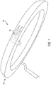
- FIG. 1 illustrates a conventional engine bleed air de-icing system 100 on an engine inlet 102.
- a nozzle swirls engine bleed air 108 around the inside of the engine inlet 102 so that the heat supplied by the engine bleed air melts ice on the engine inlet 102.
- the bleed air system has a number of limitations. Firstly, the inlet structure must accommodate high internal temperatures and pressures, which are exacerbated by a variety of failure modes and dispatch considerations. This heat management requires extra wire bundles, protections and space. Secondly, the engine idle power setting must be increased when the engine anti-ice (EAI) system is operating, so that bleed flow extraction does not exceed engine capability in this condition.
- EAI engine anti-ice
- an electrically powered heater slat is positioned on a wing leading edge so that the heater mat melts ice on the leading edge.
- the WIPS system is expensive, time consuming to service, heavy, and requires electromagnetic compatibility (EMC) and electromagnetic interference (EMI) protection.
- EMC electromagnetic compatibility
- EMI electromagnetic interference
- the power for the heater slats needs to be produced by the engine and the heat needs to be managed so it does not damage the aircraft structure.
- fuel consumption is negatively impacted because of the increased weight and power requirements of the WIPS.
- the following documents are also known.
- Document US 2016/0311542 discloses method, system, and aircraft for providing anti-ice protection comprising a supply of ferrofluid that is flowed out of orifices along a first region of an aerodynamic surface.
- the flowed ferrofluid is urged toward an aperture on a second region.
- the aperture is arranged relative to a magnetic field generator. A magnetic field generated by the magnetic field generator attracts the ferrofluid into the aperture while water droplets carried by the ferrofluid continue past the aperture.
- Document WO 2009/127652 discloses a de-icing system for an airplane, comprising at least one heat source and at least one air discharging means for discharging air in areas of the airplane to be de-iced.
- the air discharging means is connected to an air-conditioning system of the airplane by way of an air heating device for discharging air from a cabin of the airplane, wherein the air heating device is connected to the at least one heat source for heating the air of the cabin of the airplane.
- Document US 2012/0048509 discloses a method and system for thermal management which includes an engine heat exchanger configured to transfer waste heat from an engine to a heat transfer fluid and an engine exhaust heat exchanger coupled in flow communication with the engine heat exchanger wherein the engine exhaust heat exchanger is configured to transfer heat from an exhaust of the propulsive engine to the pumped heat transfer fluid.
- the heat exchanger apparatus involves the use of a heat exchanger and thermal contact with the fluid of a gear box associated with a geared fan powerplant used on an aircraft.
- the heat exchanger is in fluid communication with at least one, and more preferably a plurality, of conduits which circulate fluid heated by the fluid of the gearbox throughout the selected areas of the wings of the aircraft. This serves to selectively heat various areas of the wings to help prevent icing of the leading edge of each of the wings, as well as to increase the region of laminar flow over the wings, and thus decrease those areas where turbulent flow occurs.
- Document US 2017/030266 in accordance with its abstract, discloses a thermal management system for a gas turbine engine and/or an aircraft is provided including a thermal transport bus having a heat exchange fluid flowing therethrough.
- the thermal management system also includes a plurality of heat source exchangers and at least one heat sink exchanger.
- An electromechanical actuator heat sink is operable to receive heat from an electromechanical actuator, and a heat distribution element is operable to distribute heat to a surface.
- Described herein is an ice protection system 200 for an aerodynamic surface 206 of an aircraft 202 as disclosed in claim 1.
- a porous panel 238 on the aerodynamic surface 206 includes the outlet 232a and the coolant 218 leaks out of the porous panel 238 onto the aerodynamic surface 206.
- Locations for the porous panel 238 include, but are not limited to, on a slat, on a tail, on a wing 234, on a propeller 500, on a cockpit window 308, or an engine inlet 236.
- the coolant 218 e.g., propylene glycol combined with a thinner
- a connector 310 connects the first conduit 212 to the second conduit 232.
- the connector 310 connects the first conduit 212 to the second conduit 232 downstream (e.g. at 318) of the electronics 222, so that the coolant 218 pumped to the aerodynamic surface 206 comprises at least a portion of the heat 224 transferred from the electronics 222.
- first conduit 212 and the second conduit 232 comprise flex hoses or plastic tubing.
- the capacity of the reservoirs is adapted to provide coolant for electronics cooling system and the ice protection.
- a plurality of the reservoirs 208 may be used to store the coolant 218 and/or least one of reservoirs 208 may have a coolant 218 capacity of least 20 gallons (about 75,7 litres).
- the present disclosure further describes a method of operating an aircraft 202, as disclosed in claim 13.
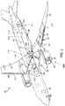
- FIG. 2 illustrates an ice protection system 200 on an aircraft 202 for preventing or suppressing ice buildup 204 on one or more aerodynamic surfaces/airfoils 206 of the aircraft 202.
- the ice protection system 200 comprises one or more reservoirs 208 and ice protection distribution system combined with an electronics cooling system 210.
- the electronics cooling system 210 includes one or more first conduits 212 (e.g., a plumbing system) connected to the one or more reservoirs 208, and one or more pumps 214 operatively coupled 216 to the one or more reservoirs 208.
- the electronics cooling system 210 distributes coolant 218 from the one or more reservoirs 208 through the one or more first conduits 212 in thermal contact 220 with electronics 222, so that heat 224 is transferred from the electronics 222 to the coolant 218.
- the electronics cooling system 210 is a primary electronics cooling system (PECS), wherein the PECS comprises two pumps 214 (e.g., 36 Gallon per minute pumps) and a reservoir 208 (disposed in the aircraft's wheel well 226).
- PECS primary electronics cooling system
- FIG. 2 further illustrates the electronics 222 comprising a first air conditioning unit or heat exchanger 228a, a direct current DC motor supplying electrical power to the aircraft electrical system, and a second back up heat exchanger at the rear of the aircraft 202.
- the heat exchanger 228a includes four compressors and four motors, motor controllers 228b controlling the motors, an electric fan, and a radiator.
- Electronics 222 may also include heat loads 228c and 228d.
- the ice protection system 200 further comprises one or more second conduits 232, or a system of conduits or distribution tubing, in communication with the one or more pumps 214 and/or the first conduit 212 and/or the one or more reservoirs 208.
- One or more of the pumps 214 pumps the liquid coolant 218 through the one or more second conduits 232 to one or more outlets 232a disposed on one or more aerodynamic surfaces 206 located on the aircraft's wing(s) 234 and engine inlet(s) 236.
- one or more porous panels 238 (connected to the one or more second conduits 232 and including one or more of the outlets 232a) are disposed on the one or more aerodynamic surfaces 206 so that the coolant 218 flows, leaks, or weeps onto the one or more aerodynamic surfaces 206 from the one or more porous panels 238. Also illustrated in FIG. 2 is hydraulic leak isolation devices 240.
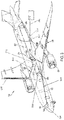
- FIG. 3 illustrates a system 300 example wherein a second conduit 302 is connected to a porous panel 304 on the aerodynamic surface 306 of a cockpit window 308 on the aircraft 202 providing ice protection window fluid 218 (e.g., for SLD, i.e. super cooled large droplet encounters).
- ice protection window fluid 218 e.g., for SLD, i.e. super cooled large droplet encounters.
- a fluid level sensor 312 is used to measure the coolant 218 level in the reservoir 208.
- One or more connectors (e.g., tees) 310 connect the one or more first conduits 212 to the one or more second conduits 232, 302.
- the connectors 310 are downstream 318 of the electronics 222, so that the coolant 218 pumped to the aerodynamic surface(s) 206, 306 comprises at least a portion of the heat 224 transferred from the electronics 222 to the coolant 218.
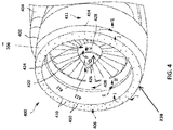
- FIG. 4 illustrates using the ice protection system according to various aspects on a gas turbine engine 400.
- the gas turbine engine includes a nacelle 402 mounted on a pylon 404.
- the pylon 404 could connect the nacelle 402 to a wing or fuselage of an aircraft, for example.
- the nacelle 402 includes a leading edge or lipskin 406.
- the leading edge or lipskin 406 includes the porous panel 238 including a plurality of orifices or outlets 410, through which the coolant comprising ice protection fluid can weep out.
- the ice protection fluid weeping out of the orifices 410 can travel in the direction of arrow I toward an inward-facing downstream surface 408 of the nacelle 402 or in the direction of arrow J toward an outward-facing downstream surface 411 of the nacelle 402.
- the inward-facing downstream surface 408 of the nacelle 402 includes an aperture 412.
- the aperture 412 could be arranged as a continuous aperture or as a series of spaced-apart apertures. Ice protection fluid traveling toward the aperture 412 can be drawn into the aperture 412 in the direction of arrow K and water carried by the ice protection fluid can continue into the engine 400 in the direction of arrow M.
- the outward-facing downstream surface 411 of the nacelle 402 includes an aperture 414.
- the aperture 414 could be arranged as a continuous aperture or as a series of spaced-apart apertures. Ice protection fluid traveling toward the aperture 414 can be drawn into the aperture 414 in the direction of arrow L and water carried by the ice protection fluid can continue aft in the direction of arrow N.
- a spinner 420 for the gas turbine engine 400 can also include a porous panel.
- An array of orifices 426 for weeping the ice protection fluid onto the spinner can be arranged on a first region 422 (e.g., an upstream region) of the spinner 420.
- An aperture 428 can be arranged on a second region 424 (e.g., a downstream region) of the spinner 420.
- the aperture 428 could be arranged as a continuous aperture or as a series of spaced-apart apertures.
- Ice protection fluid traveling from the orifices 426 (in the direction of arrow O) toward the aperture 428 can be drawn into the aperture 428 in the direction of arrow P and water carried by the ice protection fluid can continue into the engine 400 in the direction of arrow Q.
- the engines 400 used with the ice protection system are smaller and more efficient, thereby enabling more efficient and lighter aircraft.
- One or more examples of the ice protection system enable the use of engines 400 with very high bypass ratios and small cores because anti-ice bleed flow is reduced or eliminated.
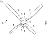
- FIG. 5 illustrates the ice protection system according to various aspects combined with an aircraft propeller 500.
- the propeller includes four propeller blades 504 extending from a spinner 502.
- An array of orifices 510 can be arranged on a first region 506 (e.g., an upstream region) of the spinner 502.
- An aperture 512 similar to aperture 412 or aperture 428 shown in FIG. 4 , can be arranged on a second region 508 (e.g., a downstream region) of the spinner 502.
- the aperture 512 could be arranged as a continuous aperture or as a series of spaced-apart apertures.
- Ice protection fluid traveling from the orifices 510 (in the direction of arrow R) toward the aperture 512 can be drawn into the aperture 512 in the direction of arrow S and water carried by the ice protection fluid can continue toward the blades 504 in the direction of arrow T.
- geared turbofan engines 400 have fans that don't spin very fast. At some point they may spin slow enough that ice can form near the hub of the blade and an anti-ice system can be used to remove ice from the hub.
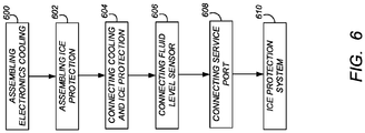
- FIG. 6 is a flowchart illustrating a method of fabricating an ice-protection apparatus (e.g., a fluid ice protection system (FIPS))
- an ice-protection apparatus e.g., a fluid ice protection system (FIPS)
- block 600 represents obtaining or assembling an electronics cooling apparatus 210.
- the electronics cooling apparatus 210 comprises a reservoir 208 or tank storing coolant; and a first conduit 212 connected to the reservoir 208, wherein heat 224 dissipates from the electronics 222 when the coolant from the reservoir 208 flows through the first conduit 212 in thermal contact 220 with the electronics 222.
- the reservoir 208 has increased capacity (e.g., at least 20 gallons, i.e about 75,7 litres) as compared to a conventional electronics cooling system reservoir/tank that is not used with an ice-protection apparatus.
- Example electronics/electrical systems cooled by the electronics cooling system 210 include, but are not limited to, a motor providing power to an air conditioning system or a liquid cooled galley on the aircraft 202.
- Block 602 represents obtaining or assembling an ice-protection distribution system 242 comprising one or more second conduits 232 including one or more outlets 232a that may be disposed on one or more aerodynamic surfaces 206 located on an outside of the aircraft 202.
- the distribution system 242 further comprises one or more porous panels 238 connected to the one or more second conduits 232 and including one or more of the outlets 232a, so that the coolant 218 flows, weeps, or leaks onto the one or more aerodynamic surfaces 206 from the one or more porous panels 238.
- Exemplary locations for the aerodynamic surface 206 include, but are not limited to, on a slat, a propeller, a cockpit window, or an engine inlet on the aircraft 202.
- the first and second conduits 212, 232 comprise flex hoses, plastic or nylon tubing, or ducting.
- liquid coolant 218 is pumped form the tank 208 to the porous panels 238 through second conduits 232 comprising branching system of nylon tubing.
- Block 604 represents connecting (e.g., using connectors 310) the ice-protection distribution system 242 to the electronics cooling apparatus 210, so that the ice-protection distribution system 242 receives the coolant 218 from the electronics cooling apparatus 210 and distributes the coolant 218 onto an aerodynamic surface 206 of the aircraft 202 through the porous panel 238.
- Block 606 represents connecting a coolant fluid monitoring/level sensor 312 measuring the coolant level in one or more of the reservoirs.
- Block 608 represents connecting a service port 314 to the reservoir 208, wherein coolant 218 in the reservoir 208 is replenished through the service port 314 when the service port 314 is connected with connection 350 to ground service equipment 316.
- Block 610 illustrates the end result, an ice protection system 200 including electronics cooling apparatus 210 distributing coolant 218 for cooling electronics 222; and an ice protection apparatus 242 connected to the electronics cooling apparatus 210, wherein the ice-protection apparatus receives the coolant 218 from the electronics cooling apparatus 210 and distributes the coolant 218 onto an aerodynamic surface 206 of the aircraft 202, the coolant 218 reducing and removing ice formation 204 on the aerodynamic surface 206.
- one or more connectors 310 connect the one or more second conduits 232 to the electronics cooling apparatus 210 downstream 318 of the electronics 222 so that the ice-protection fluid 218 distributed to the aerodynamic surface 206 comprises at least a portion of the heat 224 and reduces or prevents ice build-up 204 on the aerodynamic surface 206.
- the heat 224 helps reduce the viscosity (increase spreading) of the coolant 218, thereby improving its performance as an ice protection fluid.
- Example pumps include, but are not limited to, Direct Current (DC) motor driven pumps.
- the pumps 214 extract fluid from an unpressurized reservoir 208 and boost the pressure to at least approximately 100 psia (i.e. about 689 MPa).
- the coolant is an ice-protection fluid comprising a freezing point suppressant, including but not limited to, antifreeze, glycol based fluid such as propylene glycol, and a thinner (e.g. water).
- the thinner reduces viscosity of the coolant as compared to the coolant in an electronics cooling system 210 that is not connected to the ice protection apparatus.
- the coolant performs at least two functions (1) heat 224 dissipates from the electronics 222 when the coolant 218 flows through a portion of the electronics cooling apparatus 210 in thermal contact 220 with the electronics 222; and (2) the coolant 218 mixes with water droplets on the aerodynamic surfaces 206, lowering the freezing point of the water droplets so that the water droplets cannot freeze.
- the mixture of glycol-based fluid and water droplets then flow off the aircraft 202 together.
- the ice protection system can be mounted on a vehicle such as an aircraft 202 or high speed train so as to reduce ice buildup on the vehicle's aerodynamic surfaces (e.g., the train cockpit windows or the leading edge of an airfoil, an engine nacelle, and/or a spinner for a propeller or fan).
- a vehicle such as an aircraft 202 or high speed train so as to reduce ice buildup on the vehicle's aerodynamic surfaces (e.g., the train cockpit windows or the leading edge of an airfoil, an engine nacelle, and/or a spinner for a propeller or fan).
- FIG. 7 illustrates a method of manufacturing, refitting, or servicing an aircraft 202 including, but not limited to, commercial and military aircraft.
- the ice protection system 200 is particularly valuable on large aircraft carrying >100 passengers and having a large number of electric systems (including, e.g., a large liquid cooled galley system).
- Block 700 represents optionally mounting an electronics cooling apparatus 210 distributing coolant for cooling electronics 222 on an aircraft 202.
- the electronics cooling apparatus 210 comprises a reservoir 208 and a first conduit 212 and the step comprises connecting the first conduit 212 to the reservoir 208 and thermally contacting the first conduit 212 to electronics 222 on the aircraft 202, so that heat 224 dissipates from the electronics 222 into the coolant when the coolant from the reservoir 208 flows through the first conduit 212 in thermal contact 220 with the electronics 222.
- Block 702 represents optionally mounting an ice protection apparatus 242 on the aircraft 202 and connecting the ice-protection apparatus to the electronics cooling apparatus 210, such that the ice-protection apparatus receives the coolant 218 from the electronics cooling apparatus 210 and distributes the coolant 218 onto an aerodynamic surface 206 on outside surface of the aircraft 202.
- the coolant 218 reduces and removes/prevents ice formation 204 on the aerodynamic surface 206.
- the ice-protection apparatus 242 further comprises a second conduit 232, and the step comprises connecting the second conduit 232 to the first conduit 212 or the reservoir 208 using a connector 310, such that the connector 310 diverts at least a portion of the coolant 218 to the one or more second conduits 232 distributing the portion of the coolant 218 to an outlet 232a/porous panel or membrane 238 on an aerodynamic surface 206 on the aircraft 202.
- the step comprises positioning the connector 310 on the first conduit 212 downstream 318 of the electronics 222, so that when the coolant 218 prevents or suppresses ice formation 204 on the aerodynamic surface 206, the coolant 218 on the aerodynamic surface 206 comprises at least a portion of the heat 224 dissipated from the electronics 222.
- the step comprises positioning a porous panel 238 (e.g., between titanium sheets/panels) on the aerodynamic surface 206, wherein porous panel/membrane 238 connected to the second conduit 232 receives the coolant 218 from the second conduit 232 and the coolant 218 flows from the porous panel 238 onto the aerodynamic surface 206 on a tail or wing so as to prevent or suppress the ice build-up 204.
- a porous panel 238 e.g., between titanium sheets/panels
- the ice-protection system 242/200 is mounted on the aircraft 202 and certified during fabrication or refitting, e.g., when the aircraft 202 is re-engined. If present, the electric wing ice protection system (WIPS) is removed and replaced with the ice protection system 200.
- the WIPS controller, heavy high current wires, translating wire bundle, and heated slats in the WIPS system are replaced with the first and second conduits 232, 212 (e.g., light weight ⁇ 1/2 inch - about 1,27 cm - plastic tubing), reservoir(s) 208, and porous panels 238, as described herein.
- the pneumatic engine anti-ice system (EAI) e.g., as illustrated in FIG. 1
- a back up anti-ice system comprising heated windows is included on the aircraft 202 for SLD encounters.
- Block 704 represents optionally servicing the electronics cooling system 210 and/or ice protection system 200 (e.g., coolant 218 service). Servicing may be required more frequently when the aircraft 202 encounters icing conditions.
- the step optionally comprises replenishing or filling the coolant 218 in the reservoir 208 through a service port 314 connected to the reservoir 208 and using ground service equipment 316.
- WIPS service can be replaced by plumbing and porous panel 238 service.
- Block 706 represents optionally mounting generator(s) having lower power output as compared to generator(s) on an otherwise identical aircraft 202 without the ice protection system 200.
- the old higher power output generator(s) are removed.
- the generators mounted on the aircraft with the ice protection system 200 may be smaller with lower power output because the power requirements of one or more of the ice protection systems 200 described herein are substantially lower as compared to the power requirements of aircraft 202 using the WIPS or EAI systems.
- Block 708 represents optionally mounting or refitting the engine(s) on the aircraft 202, wherein the engine 400 (e.g., turbofan engine) has a smaller fuel consumption, as compared to the engine (e.g., turbofan engine) on an otherwise identical aircraft 202 without the ice protection system 200.
- the engines can be resized (i.e., be smaller with lower power output) because of the substantially reduced power requirements of one or more of the ice protection systems 200 described herein, as compared to the power requirements of aircraft 202 using the WIPS or EAI systems.
- WIPS systems can require a lot of power. Power requirements of example ice protections systems 200 disclosed herein can be significantly lower (e.g., more than 95% lower than WIPS).
- Block 710 represents mounting a smaller, more light weight engine inlet (e.g., including a higher composite material content), as compared to an otherwise identical aircraft 202 without the FIPS system (e.g., as compared to an aircraft 202 using WIPS or EAI for anti-icing).
- a smaller, more light weight engine inlet e.g., including a higher composite material content
- the ice protection system 200 dramatically decreases engine power demand and allows the engine, inlet, and generators to be dramatically resized, thereby improving aircraft mission performance.
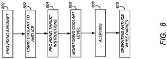
- FIG. 8 is a flowchart illustrating a method of operating the ice protection system 200 and/or aircraft 202 disclosed herein.
- Block 800 represents providing an aircraft 202 including an ice protection system 200, the ice protection system 200 comprising a reservoir 208; an electronics cooling system 210 connected to the reservoir 208 and comprising a first conduit 212; a pump 214 operatively coupled 216 to the reservoir 208; and a second conduit 232 in communication with the pump 214 and including an outlet 232a disposed at the aerodynamic surface 206 located on an outside surface of the aircraft 202.
- the electronics cooling system 210 distributes coolant 218 from the reservoir 208 through the first conduit 212 in thermal contact 220 with electronics 222, so that heat 224 is transferred from the electronics 222 to the coolant 218.
- Block 802 represents using the coolant 218 fluid to anti-ice the aerodynamic surfaces 206 of the wing during normal and super cooled large droplet (SLD) icing conditions.
- the pump 214 pumps the coolant 218 onto the aerodynamic surface 206 so that the coolant 218 reduces or prevents ice formation 204 on the aerodynamic surface 206 (e.g., the coolant 218 mixes with water on the aerodynamic surface 206 and suppresses a freezing point of the water).
- the coolant 218 fluid is used under icing conditions/envelopes as defined in 14 CFR Part 24 Appendix C or Appendix O (FAR 24 Appendix C or FAR 24 Appendix O).
- Block 804 represents optionally providing instructions allowing higher engine thrust for the aircraft 202 in icing conditions (e.g., during landing/descending), as compared to an otherwise identical aircraft 202 without the ice protection system 200.
- Block 806 represents monitoring the coolant 218 level using a fluid level sensor 312 so that the coolant 218 can be refilled after icing encounters, as needed.
- the fluid level sensor 312 sends an alert to flight, ground, or maintenance crew when the level of coolant 218 falls below a threshold level.
- Block 808 represents alerting the crew when icing conditions need to be avoided (e.g., due to low coolant 218 levels or other failures of the ice protection system 200.
- Block 810 represents optionally providing instructions allowing operation of the ice protection system 200 while the aircraft 202 is parked (even under hot ground climate conditions).
- the WIPS system on the other hand, cannot be operated on the ground while the aircraft is parked because the heated slats could damage the aircraft structure (WIPS systems need airflow during operation).
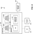
- FIG. 9 illustrates an exemplary system 900 used to implement processing elements needed to control the ice protection system, engine thrust (e.g. block 914), or other processes described herein.
- the computer 902 comprises a processor (general purpose processor 904A and special purpose processor 904B) and a memory, such as random access memory (RAM) 906.
- the computer 902 operates under control of an operating system 908 stored in the memory 906, and interfaces with the user/other computers to accept inputs and commands (e.g., analog or digital signals) and to present results through an input/output (I/O) module 910.
- the computer is connected to an electric power unit 916.
- the computer program application 912 accesses and manipulates data stored in the memory 906 of the computer 902.
- the operating system 908 and the computer program 912 are comprised of instructions which, when read and executed by the computer 902, cause the computer 902 to perform the operations herein described.
- instructions implementing the operating system 908 and the computer program 912 are tangibly embodied in the memory 906, thereby making one or more computer program products or articles of manufacture capable of controlling the ice protection system 200 and engine thrust according to the methods described herein.
- a computer connected to the fluid level sensor 312 sends an alert to flight, ground, or maintenance crew when the level of coolant 218 falls below a threshold level.
Landscapes
- Engineering & Computer Science (AREA)
- Aviation & Aerospace Engineering (AREA)
- Microelectronics & Electronic Packaging (AREA)
- Chemical & Material Sciences (AREA)
- Combustion & Propulsion (AREA)
- Physics & Mathematics (AREA)
- Thermal Sciences (AREA)
- Cooling Or The Like Of Electrical Apparatus (AREA)
- Structures Of Non-Positive Displacement Pumps (AREA)
Applications Claiming Priority (1)
| Application Number | Priority Date | Filing Date | Title |
|---|---|---|---|
| US15/720,938 US10696412B2 (en) | 2017-09-29 | 2017-09-29 | Combined fluid ice protection and electronic cooling system |
Publications (2)
| Publication Number | Publication Date |
|---|---|
| EP3461743A1 EP3461743A1 (en) | 2019-04-03 |
| EP3461743B1 true EP3461743B1 (en) | 2020-03-25 |
Family
ID=63667714
Family Applications (1)
| Application Number | Title | Priority Date | Filing Date |
|---|---|---|---|
| EP18195596.4A Active EP3461743B1 (en) | 2017-09-29 | 2018-09-20 | Combined fluid ice protection and electronics cooling system |
Country Status (5)
| Country | Link |
|---|---|
| US (1) | US10696412B2 (enExample) |
| EP (1) | EP3461743B1 (enExample) |
| JP (1) | JP7370134B2 (enExample) |
| CN (1) | CN109573054A (enExample) |
| BR (1) | BR102018069803B1 (enExample) |
Families Citing this family (12)
| Publication number | Priority date | Publication date | Assignee | Title |
|---|---|---|---|---|
| FR3078744B1 (fr) * | 2018-03-08 | 2020-11-20 | Safran Nacelles | Dispositif actif d’attenuation des emissions acoustiques pour un turboreacteur comportant des turbines controlees |
| US10759539B2 (en) * | 2018-03-30 | 2020-09-01 | The Boeing Company | Heat exchanger for mitigating ice formation on an aircraft |
| JP7348774B2 (ja) * | 2019-08-28 | 2023-09-21 | 株式会社Subaru | 電動航空機 |
| GB2587668A (en) * | 2019-10-02 | 2021-04-07 | Advanced Mobility Res And Development Ltd | Systems and methods for aircraft |
| US12015324B2 (en) | 2020-04-10 | 2024-06-18 | Hamilton Sundstrand Corporation | Motor controller electronics arrangements with actively cooled feeder cables |
| US11591096B1 (en) * | 2021-08-06 | 2023-02-28 | Raytheon Technologies Corporation | Artificial ice for an aircraft component |
| EP4140896A1 (en) | 2021-08-31 | 2023-03-01 | Eaton Intelligent Power Limited | Thermal management system |
| US12017787B2 (en) | 2021-09-07 | 2024-06-25 | Experimental Vehicle Engineering Ltd. | Aircraft propeller blade radiator |
| EP4147977B1 (en) | 2021-09-14 | 2025-05-21 | Eaton Intelligent Power Limited | Thermal management system with dual condensers |
| EP4227222B1 (en) | 2022-02-09 | 2024-05-29 | Lilium eAircraft GmbH | Airfoil of an aircraft with an ice protection system, aircraft with the airfoil and method of ice protecting the airfoil |
| US11728532B1 (en) | 2022-05-27 | 2023-08-15 | Beta Air, Llc | Electric aircraft and method of cooling a battery pack |
| CN115367118B (zh) * | 2022-08-22 | 2025-12-05 | 上海时的科技有限公司 | 一种倾转旋翼飞行器热管理系统 |
Citations (1)
| Publication number | Priority date | Publication date | Assignee | Title |
|---|---|---|---|---|
| EP0441202A1 (en) * | 1990-02-05 | 1991-08-14 | Fmc Corporation | Aircraft deicing apparatus and method |
Family Cites Families (50)
| Publication number | Priority date | Publication date | Assignee | Title |
|---|---|---|---|---|
| US2457031A (en) * | 1942-12-05 | 1948-12-21 | Borg Warner | Aircraft anti-icing arrangement |
| US2390093A (en) | 1944-03-16 | 1945-12-04 | Garrison Murray Ed | Airplane wing deicing means |
| US3116395A (en) * | 1960-04-26 | 1963-12-31 | United Control Corp | Ice detector system |
| US3423052A (en) | 1966-07-21 | 1969-01-21 | Lear Jet Ind Inc | De-icing apparatus |
| US3614038A (en) * | 1970-01-08 | 1971-10-19 | Ace Filtercraft Inc | Porous metal panel to distribute deicing fluid onto the leading edge of a surface |
| US3834157A (en) * | 1973-02-05 | 1974-09-10 | Avco Corp | Spinner de-icing for gas turbine engines |
| US4434201A (en) * | 1981-11-13 | 1984-02-28 | T.K.S. (Aircraft De-Icing) Limited | Porous panel |
| GB2130158A (en) * | 1982-11-15 | 1984-05-31 | Fiber Materials | Deicing aircraft surfaces |
| JPH01149895U (enExample) * | 1988-04-08 | 1989-10-17 | ||
| GB2314887B (en) * | 1996-07-02 | 2000-02-09 | Rolls Royce Plc | Ice protection for porous structure |
| US6688558B2 (en) | 1999-11-23 | 2004-02-10 | The Boeing Company | Method and apparatus for aircraft inlet ice protection |
| US6371411B1 (en) | 1999-11-23 | 2002-04-16 | The Boeing Company | Method and apparatus for aircraft inlet ice protection |
| FR2820715B1 (fr) * | 2001-02-15 | 2003-05-30 | Eads Airbus Sa | Procede de degivrage d'un capot d'entree d'air de moteur a reaction et dispositif pour sa mise en oeuvre |
| US6698687B2 (en) | 2002-02-13 | 2004-03-02 | The Boeing Company | Aircraft wing heat exchanger apparatus and method |
| US7723941B2 (en) * | 2003-12-29 | 2010-05-25 | The Boeing Company | System and method of command signal conditioning in high response systems |
| US7312713B2 (en) * | 2004-12-17 | 2007-12-25 | Research Foundation Of The City University Of New York | Methods and systems for detection of ice formation on surfaces |
| US20090084896A1 (en) * | 2007-09-27 | 2009-04-02 | Hamilton Sundstrand Corporation | Cabin air system for aviation electronics |
| DE102008019146A1 (de) | 2008-04-16 | 2009-11-05 | Airbus Deutschland Gmbh | Enteisungssystem für ein Flugzeug |
| DE102008039667A1 (de) * | 2008-08-26 | 2010-04-08 | Lufthansa Technik Ag | Wasseraufbereitungsvorrichtung und -verfahren für eine Trinkwasseranlage insbesondere in einem Passagierflugzeug |
| US9469408B1 (en) | 2009-09-03 | 2016-10-18 | The Boeing Company | Ice protection system and method |
| CA2911642A1 (en) * | 2010-03-14 | 2011-09-14 | Titan Logix Corp. | System and method for measuring and metering deicing fluid from a tank using a refractometer module |
| US9114877B2 (en) | 2010-08-30 | 2015-08-25 | Ge Aviation Systems, Llc | Method and system for vehicle thermal management |
| US8517601B2 (en) | 2010-09-10 | 2013-08-27 | Ultra Electronics Limited | Ice detection system and method |
| US9016633B2 (en) | 2011-06-13 | 2015-04-28 | The Boeing Company | Electromechanical actuator (EMA) heat sink integrated de-icing system |
| US9670875B2 (en) | 2012-10-31 | 2017-06-06 | The Boeing Company | Thrust reversers and methods to provide reverse thrust |
| US9528442B2 (en) * | 2013-08-21 | 2016-12-27 | The Boeing Company | Aircraft engine anti-icing (EAI) barrier assembly, system and method |
| US9612163B2 (en) * | 2013-10-10 | 2017-04-04 | The Boeing Company | Methods and apparatus for detecting ice formation on aircraft |
| US9764847B2 (en) | 2013-10-18 | 2017-09-19 | The Boeing Company | Anti-icing system for aircraft |
| US10138811B2 (en) | 2014-03-13 | 2018-11-27 | The Boeing Company | Enhanced temperature control anti-ice nozzle |
| US9546004B1 (en) | 2014-03-17 | 2017-01-17 | The Boeing Company | Water and ice detection and quantitative assessment system for ingression prone areas in an aircraft |
| AU2015268086B2 (en) | 2014-05-30 | 2019-03-28 | Commonwealth Scientific And Industrial Research Organisation | Ice adhesion reducing polymers |
| EP3789392B1 (en) | 2014-05-30 | 2023-05-10 | Commonwealth Scientific and Industrial Research Organisation | Ice adhesion reducing prepolymers and polymers |
| US9429680B2 (en) | 2014-08-07 | 2016-08-30 | The Boeing Company | Ice crystal icing engine event probability estimation apparatus, system, and method |
| US9242735B1 (en) | 2014-08-28 | 2016-01-26 | The Boeing Company | Detecting inflight icing conditions on aircraft |
| US9696238B2 (en) | 2014-09-16 | 2017-07-04 | The Boeing Company | Systems and methods for icing flight tests |
| US10144522B2 (en) | 2015-04-16 | 2018-12-04 | The Boeing Company | Weeping ferrofluid anti-ice system |
| US20160356180A1 (en) | 2015-06-03 | 2016-12-08 | The Boeing Company | Nacelle inlet having an angle or curved aft bulkhead |
| US10486821B2 (en) | 2015-07-07 | 2019-11-26 | The Boeing Company | Jet engine anti-icing and noise-attenuating air inlets |
| US10260419B2 (en) * | 2015-07-31 | 2019-04-16 | General Electric Company | Cooling system |
| US10442523B2 (en) | 2015-08-25 | 2019-10-15 | The Boeing Company | Synergetic noise absorption and anti-icing for aircrafts |
| US10737793B2 (en) | 2015-12-02 | 2020-08-11 | The Boeing Company | Aircraft ice detection systems and methods |
| US9914543B2 (en) | 2015-12-09 | 2018-03-13 | The Boeing Company | System and method for aircraft ice detection within a zone of non-detection |
| US10823066B2 (en) | 2015-12-09 | 2020-11-03 | General Electric Company | Thermal management system |
| US10160548B2 (en) | 2016-01-04 | 2018-12-25 | The Boeing Company | Apparatuses and methods for anti-icing of speed measurement probes |
| CN105691620B (zh) * | 2016-01-20 | 2018-04-24 | 南京师范大学 | 利用飞机发动机余热的热管超声波联合防冰除冰装置及方法 |
| US10377498B2 (en) | 2016-01-21 | 2019-08-13 | The Boeing Company | Aircraft and associated method for providing electrical energy to an anti-icing system |
| JP6654483B2 (ja) | 2016-03-24 | 2020-02-26 | 三菱航空機株式会社 | 航空機の防氷システム、それを備えた航空機、防氷システム制御プログラム、および防氷システムの制御方法 |
| CN106184768A (zh) * | 2016-07-22 | 2016-12-07 | 中国航空工业集团公司西安飞机设计研究所 | 一种自适应机翼热气除冰系统 |
| US10252808B2 (en) | 2016-09-22 | 2019-04-09 | The Boeing Company | Fluid ice protection system flow conductivity sensor |
| US10737792B2 (en) | 2016-09-22 | 2020-08-11 | The Boeing Company | Turbofan engine fluid ice protection delivery system |
-
2017
- 2017-09-29 US US15/720,938 patent/US10696412B2/en active Active
-
2018
- 2018-09-20 EP EP18195596.4A patent/EP3461743B1/en active Active
- 2018-09-27 CN CN201811128611.9A patent/CN109573054A/zh active Pending
- 2018-09-27 BR BR102018069803-6A patent/BR102018069803B1/pt active IP Right Grant
- 2018-09-28 JP JP2018183121A patent/JP7370134B2/ja active Active
Patent Citations (1)
| Publication number | Priority date | Publication date | Assignee | Title |
|---|---|---|---|---|
| EP0441202A1 (en) * | 1990-02-05 | 1991-08-14 | Fmc Corporation | Aircraft deicing apparatus and method |
Also Published As
| Publication number | Publication date |
|---|---|
| JP7370134B2 (ja) | 2023-10-27 |
| BR102018069803A2 (pt) | 2019-06-04 |
| BR102018069803B1 (pt) | 2023-12-19 |
| US20190100319A1 (en) | 2019-04-04 |
| US10696412B2 (en) | 2020-06-30 |
| EP3461743A1 (en) | 2019-04-03 |
| CN109573054A (zh) | 2019-04-05 |
| JP2019081537A (ja) | 2019-05-30 |
Similar Documents
| Publication | Publication Date | Title |
|---|---|---|
| EP3461743B1 (en) | Combined fluid ice protection and electronics cooling system | |
| US11982229B2 (en) | Advanced inlet design | |
| US10737792B2 (en) | Turbofan engine fluid ice protection delivery system | |
| US5114100A (en) | Anti-icing system for aircraft | |
| US8857767B2 (en) | De-icing system for an aircraft | |
| US6725645B1 (en) | Turbofan engine internal anti-ice device | |
| CN104136322B (zh) | 装有热交换器的涡轮发动机机舱 | |
| CN105612105B (zh) | 用于飞机的防结冰系统和方法 | |
| US10125683B2 (en) | De-icing and conditioning device for an aircraft | |
| CN102695862A (zh) | 涡轮发动机推进单元的流体冷却装置 | |
| EP1935783B1 (en) | Ice protection system including a plurality of segmented sub-areas and a cyclic diverter valve | |
| US20200247548A1 (en) | Apparatus and methods for providing air to pneumatic loads onboard aircraft | |
| EP4301659B1 (en) | System and method for generating electrical energy from thermal waste energy and removing thermal waste energy in an aircraft | |
| Ingram et al. | Integrating Subsystem Sizing into the More Electric Aircraft Conceptual Design Phase | |
| CN115230969A (zh) | 一种采用涡流管的防除冰和电子设备冷却的飞行器环控系统及方法 | |
| Heersema et al. | Computational Heat Flux Analysis for HEATheR Electric Aircraft Wing Ice Protection Systems | |
| Heersema | Heat Flux Requirements for Electrified Aircraft Wing Anti-Ice Systems | |
| Humphreys et al. | Flight testing of a HLF wing with suction, ice-protection and anti-contamination systems |
Legal Events
| Date | Code | Title | Description |
|---|---|---|---|
| STAA | Information on the status of an ep patent application or granted ep patent |
Free format text: STATUS: EXAMINATION IS IN PROGRESS |
|
| PUAI | Public reference made under article 153(3) epc to a published international application that has entered the european phase |
Free format text: ORIGINAL CODE: 0009012 |
|
| 17P | Request for examination filed |
Effective date: 20180920 |
|
| AK | Designated contracting states |
Kind code of ref document: A1 Designated state(s): AL AT BE BG CH CY CZ DE DK EE ES FI FR GB GR HR HU IE IS IT LI LT LU LV MC MK MT NL NO PL PT RO RS SE SI SK SM TR |
|
| AX | Request for extension of the european patent |
Extension state: BA ME |
|
| GRAP | Despatch of communication of intention to grant a patent |
Free format text: ORIGINAL CODE: EPIDOSNIGR1 |
|
| STAA | Information on the status of an ep patent application or granted ep patent |
Free format text: STATUS: GRANT OF PATENT IS INTENDED |
|
| RIC1 | Information provided on ipc code assigned before grant |
Ipc: B64D 13/06 20060101ALN20190926BHEP Ipc: B64D 33/02 20060101ALI20190926BHEP Ipc: B64D 15/02 20060101AFI20190926BHEP Ipc: B64D 15/00 20060101ALI20190926BHEP Ipc: B64D 15/08 20060101ALI20190926BHEP |
|
| INTG | Intention to grant announced |
Effective date: 20191025 |
|
| RIN1 | Information on inventor provided before grant (corrected) |
Inventor name: MACKIN, STEVE G. |
|
| GRAS | Grant fee paid |
Free format text: ORIGINAL CODE: EPIDOSNIGR3 |
|
| GRAA | (expected) grant |
Free format text: ORIGINAL CODE: 0009210 |
|
| STAA | Information on the status of an ep patent application or granted ep patent |
Free format text: STATUS: THE PATENT HAS BEEN GRANTED |
|
| AK | Designated contracting states |
Kind code of ref document: B1 Designated state(s): AL AT BE BG CH CY CZ DE DK EE ES FI FR GB GR HR HU IE IS IT LI LT LU LV MC MK MT NL NO PL PT RO RS SE SI SK SM TR |
|
| REG | Reference to a national code |
Ref country code: GB Ref legal event code: FG4D |
|
| REG | Reference to a national code |
Ref country code: AT Ref legal event code: REF Ref document number: 1248288 Country of ref document: AT Kind code of ref document: T Effective date: 20200415 Ref country code: IE Ref legal event code: FG4D |
|
| REG | Reference to a national code |
Ref country code: DE Ref legal event code: R096 Ref document number: 602018003267 Country of ref document: DE |
|
| PG25 | Lapsed in a contracting state [announced via postgrant information from national office to epo] |
Ref country code: NO Free format text: LAPSE BECAUSE OF FAILURE TO SUBMIT A TRANSLATION OF THE DESCRIPTION OR TO PAY THE FEE WITHIN THE PRESCRIBED TIME-LIMIT Effective date: 20200625 Ref country code: FI Free format text: LAPSE BECAUSE OF FAILURE TO SUBMIT A TRANSLATION OF THE DESCRIPTION OR TO PAY THE FEE WITHIN THE PRESCRIBED TIME-LIMIT Effective date: 20200325 Ref country code: RS Free format text: LAPSE BECAUSE OF FAILURE TO SUBMIT A TRANSLATION OF THE DESCRIPTION OR TO PAY THE FEE WITHIN THE PRESCRIBED TIME-LIMIT Effective date: 20200325 |
|
| PG25 | Lapsed in a contracting state [announced via postgrant information from national office to epo] |
Ref country code: HR Free format text: LAPSE BECAUSE OF FAILURE TO SUBMIT A TRANSLATION OF THE DESCRIPTION OR TO PAY THE FEE WITHIN THE PRESCRIBED TIME-LIMIT Effective date: 20200325 Ref country code: BG Free format text: LAPSE BECAUSE OF FAILURE TO SUBMIT A TRANSLATION OF THE DESCRIPTION OR TO PAY THE FEE WITHIN THE PRESCRIBED TIME-LIMIT Effective date: 20200625 Ref country code: LV Free format text: LAPSE BECAUSE OF FAILURE TO SUBMIT A TRANSLATION OF THE DESCRIPTION OR TO PAY THE FEE WITHIN THE PRESCRIBED TIME-LIMIT Effective date: 20200325 Ref country code: SE Free format text: LAPSE BECAUSE OF FAILURE TO SUBMIT A TRANSLATION OF THE DESCRIPTION OR TO PAY THE FEE WITHIN THE PRESCRIBED TIME-LIMIT Effective date: 20200325 Ref country code: GR Free format text: LAPSE BECAUSE OF FAILURE TO SUBMIT A TRANSLATION OF THE DESCRIPTION OR TO PAY THE FEE WITHIN THE PRESCRIBED TIME-LIMIT Effective date: 20200626 |
|
| REG | Reference to a national code |
Ref country code: NL Ref legal event code: MP Effective date: 20200325 |
|
| REG | Reference to a national code |
Ref country code: LT Ref legal event code: MG4D |
|
| PG25 | Lapsed in a contracting state [announced via postgrant information from national office to epo] |
Ref country code: NL Free format text: LAPSE BECAUSE OF FAILURE TO SUBMIT A TRANSLATION OF THE DESCRIPTION OR TO PAY THE FEE WITHIN THE PRESCRIBED TIME-LIMIT Effective date: 20200325 |
|
| PG25 | Lapsed in a contracting state [announced via postgrant information from national office to epo] |
Ref country code: LT Free format text: LAPSE BECAUSE OF FAILURE TO SUBMIT A TRANSLATION OF THE DESCRIPTION OR TO PAY THE FEE WITHIN THE PRESCRIBED TIME-LIMIT Effective date: 20200325 Ref country code: SM Free format text: LAPSE BECAUSE OF FAILURE TO SUBMIT A TRANSLATION OF THE DESCRIPTION OR TO PAY THE FEE WITHIN THE PRESCRIBED TIME-LIMIT Effective date: 20200325 Ref country code: EE Free format text: LAPSE BECAUSE OF FAILURE TO SUBMIT A TRANSLATION OF THE DESCRIPTION OR TO PAY THE FEE WITHIN THE PRESCRIBED TIME-LIMIT Effective date: 20200325 Ref country code: CZ Free format text: LAPSE BECAUSE OF FAILURE TO SUBMIT A TRANSLATION OF THE DESCRIPTION OR TO PAY THE FEE WITHIN THE PRESCRIBED TIME-LIMIT Effective date: 20200325 Ref country code: IS Free format text: LAPSE BECAUSE OF FAILURE TO SUBMIT A TRANSLATION OF THE DESCRIPTION OR TO PAY THE FEE WITHIN THE PRESCRIBED TIME-LIMIT Effective date: 20200725 Ref country code: RO Free format text: LAPSE BECAUSE OF FAILURE TO SUBMIT A TRANSLATION OF THE DESCRIPTION OR TO PAY THE FEE WITHIN THE PRESCRIBED TIME-LIMIT Effective date: 20200325 Ref country code: SK Free format text: LAPSE BECAUSE OF FAILURE TO SUBMIT A TRANSLATION OF THE DESCRIPTION OR TO PAY THE FEE WITHIN THE PRESCRIBED TIME-LIMIT Effective date: 20200325 Ref country code: PT Free format text: LAPSE BECAUSE OF FAILURE TO SUBMIT A TRANSLATION OF THE DESCRIPTION OR TO PAY THE FEE WITHIN THE PRESCRIBED TIME-LIMIT Effective date: 20200818 |
|
| REG | Reference to a national code |
Ref country code: AT Ref legal event code: MK05 Ref document number: 1248288 Country of ref document: AT Kind code of ref document: T Effective date: 20200325 |
|
| REG | Reference to a national code |
Ref country code: DE Ref legal event code: R097 Ref document number: 602018003267 Country of ref document: DE |
|
| PG25 | Lapsed in a contracting state [announced via postgrant information from national office to epo] |
Ref country code: AT Free format text: LAPSE BECAUSE OF FAILURE TO SUBMIT A TRANSLATION OF THE DESCRIPTION OR TO PAY THE FEE WITHIN THE PRESCRIBED TIME-LIMIT Effective date: 20200325 Ref country code: DK Free format text: LAPSE BECAUSE OF FAILURE TO SUBMIT A TRANSLATION OF THE DESCRIPTION OR TO PAY THE FEE WITHIN THE PRESCRIBED TIME-LIMIT Effective date: 20200325 Ref country code: IT Free format text: LAPSE BECAUSE OF FAILURE TO SUBMIT A TRANSLATION OF THE DESCRIPTION OR TO PAY THE FEE WITHIN THE PRESCRIBED TIME-LIMIT Effective date: 20200325 Ref country code: ES Free format text: LAPSE BECAUSE OF FAILURE TO SUBMIT A TRANSLATION OF THE DESCRIPTION OR TO PAY THE FEE WITHIN THE PRESCRIBED TIME-LIMIT Effective date: 20200325 |
|
| PLBE | No opposition filed within time limit |
Free format text: ORIGINAL CODE: 0009261 |
|
| STAA | Information on the status of an ep patent application or granted ep patent |
Free format text: STATUS: NO OPPOSITION FILED WITHIN TIME LIMIT |
|
| PG25 | Lapsed in a contracting state [announced via postgrant information from national office to epo] |
Ref country code: PL Free format text: LAPSE BECAUSE OF FAILURE TO SUBMIT A TRANSLATION OF THE DESCRIPTION OR TO PAY THE FEE WITHIN THE PRESCRIBED TIME-LIMIT Effective date: 20200325 |
|
| 26N | No opposition filed |
Effective date: 20210112 |
|
| PG25 | Lapsed in a contracting state [announced via postgrant information from national office to epo] |
Ref country code: SI Free format text: LAPSE BECAUSE OF FAILURE TO SUBMIT A TRANSLATION OF THE DESCRIPTION OR TO PAY THE FEE WITHIN THE PRESCRIBED TIME-LIMIT Effective date: 20200325 |
|
| REG | Reference to a national code |
Ref country code: BE Ref legal event code: MM Effective date: 20200930 |
|
| PG25 | Lapsed in a contracting state [announced via postgrant information from national office to epo] |
Ref country code: LU Free format text: LAPSE BECAUSE OF NON-PAYMENT OF DUE FEES Effective date: 20200920 |
|
| PG25 | Lapsed in a contracting state [announced via postgrant information from national office to epo] |
Ref country code: IE Free format text: LAPSE BECAUSE OF NON-PAYMENT OF DUE FEES Effective date: 20200920 Ref country code: BE Free format text: LAPSE BECAUSE OF NON-PAYMENT OF DUE FEES Effective date: 20200930 |
|
| REG | Reference to a national code |
Ref country code: CH Ref legal event code: PL |
|
| PG25 | Lapsed in a contracting state [announced via postgrant information from national office to epo] |
Ref country code: TR Free format text: LAPSE BECAUSE OF FAILURE TO SUBMIT A TRANSLATION OF THE DESCRIPTION OR TO PAY THE FEE WITHIN THE PRESCRIBED TIME-LIMIT Effective date: 20200325 Ref country code: MT Free format text: LAPSE BECAUSE OF FAILURE TO SUBMIT A TRANSLATION OF THE DESCRIPTION OR TO PAY THE FEE WITHIN THE PRESCRIBED TIME-LIMIT Effective date: 20200325 Ref country code: CY Free format text: LAPSE BECAUSE OF FAILURE TO SUBMIT A TRANSLATION OF THE DESCRIPTION OR TO PAY THE FEE WITHIN THE PRESCRIBED TIME-LIMIT Effective date: 20200325 |
|
| PG25 | Lapsed in a contracting state [announced via postgrant information from national office to epo] |
Ref country code: MK Free format text: LAPSE BECAUSE OF FAILURE TO SUBMIT A TRANSLATION OF THE DESCRIPTION OR TO PAY THE FEE WITHIN THE PRESCRIBED TIME-LIMIT Effective date: 20200325 Ref country code: MC Free format text: LAPSE BECAUSE OF FAILURE TO SUBMIT A TRANSLATION OF THE DESCRIPTION OR TO PAY THE FEE WITHIN THE PRESCRIBED TIME-LIMIT Effective date: 20200325 Ref country code: AL Free format text: LAPSE BECAUSE OF FAILURE TO SUBMIT A TRANSLATION OF THE DESCRIPTION OR TO PAY THE FEE WITHIN THE PRESCRIBED TIME-LIMIT Effective date: 20200325 |
|
| PG25 | Lapsed in a contracting state [announced via postgrant information from national office to epo] |
Ref country code: LI Free format text: LAPSE BECAUSE OF NON-PAYMENT OF DUE FEES Effective date: 20210930 Ref country code: CH Free format text: LAPSE BECAUSE OF NON-PAYMENT OF DUE FEES Effective date: 20210930 |
|
| P01 | Opt-out of the competence of the unified patent court (upc) registered |
Effective date: 20230516 |
|
| PGFP | Annual fee paid to national office [announced via postgrant information from national office to epo] |
Ref country code: DE Payment date: 20250929 Year of fee payment: 8 |
|
| PGFP | Annual fee paid to national office [announced via postgrant information from national office to epo] |
Ref country code: GB Payment date: 20250929 Year of fee payment: 8 |
|
| PGFP | Annual fee paid to national office [announced via postgrant information from national office to epo] |
Ref country code: FR Payment date: 20250925 Year of fee payment: 8 |