US11728532B1 - Electric aircraft and method of cooling a battery pack - Google Patents
Electric aircraft and method of cooling a battery pack Download PDFInfo
- Publication number
- US11728532B1 US11728532B1 US17/827,002 US202217827002A US11728532B1 US 11728532 B1 US11728532 B1 US 11728532B1 US 202217827002 A US202217827002 A US 202217827002A US 11728532 B1 US11728532 B1 US 11728532B1
- Authority
- US
- United States
- Prior art keywords
- battery pack
- aircraft
- battery
- coolant
- flight
- Prior art date
- Legal status (The legal status is an assumption and is not a legal conclusion. Google has not performed a legal analysis and makes no representation as to the accuracy of the status listed.)
- Active
Links
- 238000000034 method Methods 0.000 title description 126
- 238000001816 cooling Methods 0.000 title description 29
- 239000002826 coolant Substances 0.000 claims abstract description 137
- 238000004891 communication Methods 0.000 claims abstract description 36
- 230000037361 pathway Effects 0.000 claims abstract description 25
- 230000006870 function Effects 0.000 claims description 132
- 238000005457 optimization Methods 0.000 claims description 20
- 238000010801 machine learning Methods 0.000 description 86
- 230000008569 process Effects 0.000 description 81
- 238000004422 calculation algorithm Methods 0.000 description 75
- 238000007726 management method Methods 0.000 description 63
- 230000000670 limiting effect Effects 0.000 description 61
- 238000012549 training Methods 0.000 description 44
- 238000005259 measurement Methods 0.000 description 38
- 230000008878 coupling Effects 0.000 description 28
- 238000010168 coupling process Methods 0.000 description 28
- 238000005859 coupling reaction Methods 0.000 description 28
- 238000012545 processing Methods 0.000 description 27
- 239000007789 gas Substances 0.000 description 22
- 230000009471 action Effects 0.000 description 21
- 238000013500 data storage Methods 0.000 description 19
- 239000000463 material Substances 0.000 description 17
- 238000003860 storage Methods 0.000 description 15
- 230000009466 transformation Effects 0.000 description 14
- XLYOFNOQVPJJNP-UHFFFAOYSA-N water Substances O XLYOFNOQVPJJNP-UHFFFAOYSA-N 0.000 description 14
- 238000013528 artificial neural network Methods 0.000 description 12
- 230000002093 peripheral effect Effects 0.000 description 12
- 238000012417 linear regression Methods 0.000 description 11
- 238000004458 analytical method Methods 0.000 description 10
- 239000012530 fluid Substances 0.000 description 10
- 230000033001 locomotion Effects 0.000 description 9
- 230000009467 reduction Effects 0.000 description 9
- 238000004088 simulation Methods 0.000 description 9
- 238000006243 chemical reaction Methods 0.000 description 8
- 230000000875 corresponding effect Effects 0.000 description 8
- 238000013479 data entry Methods 0.000 description 8
- 238000001514 detection method Methods 0.000 description 8
- 230000008859 change Effects 0.000 description 7
- 238000013461 design Methods 0.000 description 7
- 238000012423 maintenance Methods 0.000 description 7
- 230000002441 reversible effect Effects 0.000 description 7
- 239000000126 substance Substances 0.000 description 7
- RZVHIXYEVGDQDX-UHFFFAOYSA-N 9,10-anthraquinone Chemical compound C1=CC=C2C(=O)C3=CC=CC=C3C(=O)C2=C1 RZVHIXYEVGDQDX-UHFFFAOYSA-N 0.000 description 6
- 238000010586 diagram Methods 0.000 description 6
- 238000009826 distribution Methods 0.000 description 6
- 239000007788 liquid Substances 0.000 description 6
- 230000007257 malfunction Effects 0.000 description 6
- 230000003287 optical effect Effects 0.000 description 6
- 230000011218 segmentation Effects 0.000 description 6
- 238000012546 transfer Methods 0.000 description 6
- 238000010276 construction Methods 0.000 description 5
- 238000012937 correction Methods 0.000 description 5
- 238000003066 decision tree Methods 0.000 description 5
- 239000000446 fuel Substances 0.000 description 5
- 238000002955 isolation Methods 0.000 description 5
- 238000012544 monitoring process Methods 0.000 description 5
- -1 polyethylene Polymers 0.000 description 5
- 230000001172 regenerating effect Effects 0.000 description 5
- 230000001105 regulatory effect Effects 0.000 description 5
- 238000012706 support-vector machine Methods 0.000 description 5
- XEEYBQQBJWHFJM-UHFFFAOYSA-N Iron Chemical compound [Fe] XEEYBQQBJWHFJM-UHFFFAOYSA-N 0.000 description 4
- 238000007792 addition Methods 0.000 description 4
- 239000006227 byproduct Substances 0.000 description 4
- 230000001276 controlling effect Effects 0.000 description 4
- 230000002596 correlated effect Effects 0.000 description 4
- 239000011152 fibreglass Substances 0.000 description 4
- 230000017525 heat dissipation Effects 0.000 description 4
- 238000003384 imaging method Methods 0.000 description 4
- 230000007246 mechanism Effects 0.000 description 4
- 230000001537 neural effect Effects 0.000 description 4
- 239000013598 vector Substances 0.000 description 4
- CURLTUGMZLYLDI-UHFFFAOYSA-N Carbon dioxide Chemical compound O=C=O CURLTUGMZLYLDI-UHFFFAOYSA-N 0.000 description 3
- LYCAIKOWRPUZTN-UHFFFAOYSA-N Ethylene glycol Chemical compound OCCO LYCAIKOWRPUZTN-UHFFFAOYSA-N 0.000 description 3
- OKKJLVBELUTLKV-UHFFFAOYSA-N Methanol Chemical compound OC OKKJLVBELUTLKV-UHFFFAOYSA-N 0.000 description 3
- DNIAPMSPPWPWGF-UHFFFAOYSA-N Propylene glycol Chemical compound CC(O)CO DNIAPMSPPWPWGF-UHFFFAOYSA-N 0.000 description 3
- 229910000831 Steel Inorganic materials 0.000 description 3
- QVGXLLKOCUKJST-UHFFFAOYSA-N atomic oxygen Chemical compound [O] QVGXLLKOCUKJST-UHFFFAOYSA-N 0.000 description 3
- 238000007635 classification algorithm Methods 0.000 description 3
- 239000000470 constituent Substances 0.000 description 3
- 230000005611 electricity Effects 0.000 description 3
- 238000007710 freezing Methods 0.000 description 3
- 230000008014 freezing Effects 0.000 description 3
- 239000011521 glass Substances 0.000 description 3
- 230000036541 health Effects 0.000 description 3
- 238000009413 insulation Methods 0.000 description 3
- 230000002452 interceptive effect Effects 0.000 description 3
- 238000007477 logistic regression Methods 0.000 description 3
- VNWKTOKETHGBQD-UHFFFAOYSA-N methane Chemical compound C VNWKTOKETHGBQD-UHFFFAOYSA-N 0.000 description 3
- 239000001301 oxygen Substances 0.000 description 3
- 229910052760 oxygen Inorganic materials 0.000 description 3
- 238000007637 random forest analysis Methods 0.000 description 3
- 239000005060 rubber Substances 0.000 description 3
- 239000004065 semiconductor Substances 0.000 description 3
- 239000010959 steel Substances 0.000 description 3
- 230000001131 transforming effect Effects 0.000 description 3
- 230000000007 visual effect Effects 0.000 description 3
- RYGMFSIKBFXOCR-UHFFFAOYSA-N Copper Chemical compound [Cu] RYGMFSIKBFXOCR-UHFFFAOYSA-N 0.000 description 2
- PXHVJJICTQNCMI-UHFFFAOYSA-N Nickel Chemical compound [Ni] PXHVJJICTQNCMI-UHFFFAOYSA-N 0.000 description 2
- NBIIXXVUZAFLBC-UHFFFAOYSA-N Phosphoric acid Chemical compound OP(O)(O)=O NBIIXXVUZAFLBC-UHFFFAOYSA-N 0.000 description 2
- 239000004809 Teflon Substances 0.000 description 2
- 229920006362 Teflon® Polymers 0.000 description 2
- 230000004931 aggregating effect Effects 0.000 description 2
- 229910052782 aluminium Inorganic materials 0.000 description 2
- XAGFODPZIPBFFR-UHFFFAOYSA-N aluminium Chemical compound [Al] XAGFODPZIPBFFR-UHFFFAOYSA-N 0.000 description 2
- 230000003321 amplification Effects 0.000 description 2
- 239000010425 asbestos Substances 0.000 description 2
- 230000004888 barrier function Effects 0.000 description 2
- 230000009286 beneficial effect Effects 0.000 description 2
- 230000005540 biological transmission Effects 0.000 description 2
- 229960004424 carbon dioxide Drugs 0.000 description 2
- 230000015556 catabolic process Effects 0.000 description 2
- 238000013527 convolutional neural network Methods 0.000 description 2
- 239000010949 copper Substances 0.000 description 2
- 229910052802 copper Inorganic materials 0.000 description 2
- 238000013135 deep learning Methods 0.000 description 2
- 238000006731 degradation reaction Methods 0.000 description 2
- 230000001419 dependent effect Effects 0.000 description 2
- 230000000779 depleting effect Effects 0.000 description 2
- 238000004146 energy storage Methods 0.000 description 2
- 238000011156 evaluation Methods 0.000 description 2
- 239000000835 fiber Substances 0.000 description 2
- 238000007667 floating Methods 0.000 description 2
- 239000011888 foil Substances 0.000 description 2
- 239000001257 hydrogen Substances 0.000 description 2
- 229910052739 hydrogen Inorganic materials 0.000 description 2
- 230000001965 increasing effect Effects 0.000 description 2
- 230000006698 induction Effects 0.000 description 2
- 229920000554 ionomer Polymers 0.000 description 2
- 229910052742 iron Inorganic materials 0.000 description 2
- 238000011068 loading method Methods 0.000 description 2
- 238000013507 mapping Methods 0.000 description 2
- 239000011159 matrix material Substances 0.000 description 2
- 229910052751 metal Inorganic materials 0.000 description 2
- 239000002184 metal Substances 0.000 description 2
- 238000010295 mobile communication Methods 0.000 description 2
- 238000012986 modification Methods 0.000 description 2
- 230000004048 modification Effects 0.000 description 2
- 238000003199 nucleic acid amplification method Methods 0.000 description 2
- 238000013021 overheating Methods 0.000 description 2
- 239000000123 paper Substances 0.000 description 2
- 239000004033 plastic Substances 0.000 description 2
- 229920003023 plastic Polymers 0.000 description 2
- 239000002985 plastic film Substances 0.000 description 2
- 229920006255 plastic film Polymers 0.000 description 2
- 229920000642 polymer Polymers 0.000 description 2
- 229920006327 polystyrene foam Polymers 0.000 description 2
- 239000004800 polyvinyl chloride Substances 0.000 description 2
- 238000000513 principal component analysis Methods 0.000 description 2
- 239000000047 product Substances 0.000 description 2
- 230000005855 radiation Effects 0.000 description 2
- 238000011084 recovery Methods 0.000 description 2
- 230000002829 reductive effect Effects 0.000 description 2
- 239000011347 resin Substances 0.000 description 2
- 229920005989 resin Polymers 0.000 description 2
- 230000004044 response Effects 0.000 description 2
- 229910052895 riebeckite Inorganic materials 0.000 description 2
- 238000000926 separation method Methods 0.000 description 2
- 230000035939 shock Effects 0.000 description 2
- 238000002922 simulated annealing Methods 0.000 description 2
- 239000000779 smoke Substances 0.000 description 2
- 230000001360 synchronised effect Effects 0.000 description 2
- 239000002966 varnish Substances 0.000 description 2
- 238000013022 venting Methods 0.000 description 2
- 239000002023 wood Substances 0.000 description 2
- 229910000851 Alloy steel Inorganic materials 0.000 description 1
- 238000012935 Averaging Methods 0.000 description 1
- 229920002799 BoPET Polymers 0.000 description 1
- 229920000049 Carbon (fiber) Polymers 0.000 description 1
- UGFAIRIUMAVXCW-UHFFFAOYSA-N Carbon monoxide Chemical compound [O+]#[C-] UGFAIRIUMAVXCW-UHFFFAOYSA-N 0.000 description 1
- 229910000975 Carbon steel Inorganic materials 0.000 description 1
- 229910000881 Cu alloy Inorganic materials 0.000 description 1
- 239000004593 Epoxy Substances 0.000 description 1
- UFHFLCQGNIYNRP-UHFFFAOYSA-N Hydrogen Chemical compound [H][H] UFHFLCQGNIYNRP-UHFFFAOYSA-N 0.000 description 1
- 229910000792 Monel Inorganic materials 0.000 description 1
- 239000005041 Mylar™ Substances 0.000 description 1
- 239000004698 Polyethylene Substances 0.000 description 1
- 229910001362 Ta alloys Inorganic materials 0.000 description 1
- RTAQQCXQSZGOHL-UHFFFAOYSA-N Titanium Chemical compound [Ti] RTAQQCXQSZGOHL-UHFFFAOYSA-N 0.000 description 1
- 229910001080 W alloy Inorganic materials 0.000 description 1
- 238000009825 accumulation Methods 0.000 description 1
- 230000002776 aggregation Effects 0.000 description 1
- 238000004220 aggregation Methods 0.000 description 1
- 239000003570 air Substances 0.000 description 1
- 239000012670 alkaline solution Substances 0.000 description 1
- WYTGDNHDOZPMIW-RCBQFDQVSA-N alstonine Natural products C1=CC2=C3C=CC=CC3=NC2=C2N1C[C@H]1[C@H](C)OC=C(C(=O)OC)[C@H]1C2 WYTGDNHDOZPMIW-RCBQFDQVSA-N 0.000 description 1
- 230000004075 alteration Effects 0.000 description 1
- 229910000147 aluminium phosphate Inorganic materials 0.000 description 1
- 238000003491 array Methods 0.000 description 1
- 230000008901 benefit Effects 0.000 description 1
- 230000037237 body shape Effects 0.000 description 1
- 239000003990 capacitor Substances 0.000 description 1
- 229910002092 carbon dioxide Inorganic materials 0.000 description 1
- 239000001569 carbon dioxide Substances 0.000 description 1
- 235000011089 carbon dioxide Nutrition 0.000 description 1
- 239000004917 carbon fiber Substances 0.000 description 1
- 229910002091 carbon monoxide Inorganic materials 0.000 description 1
- 239000010962 carbon steel Substances 0.000 description 1
- 239000002131 composite material Substances 0.000 description 1
- 150000001875 compounds Chemical class 0.000 description 1
- 238000004590 computer program Methods 0.000 description 1
- 238000009833 condensation Methods 0.000 description 1
- 230000005494 condensation Effects 0.000 description 1
- 230000003750 conditioning effect Effects 0.000 description 1
- YOCUPQPZWBBYIX-UHFFFAOYSA-N copper nickel Chemical compound [Ni].[Cu] YOCUPQPZWBBYIX-UHFFFAOYSA-N 0.000 description 1
- 238000010219 correlation analysis Methods 0.000 description 1
- 238000000354 decomposition reaction Methods 0.000 description 1
- 230000001627 detrimental effect Effects 0.000 description 1
- 238000011161 development Methods 0.000 description 1
- 230000018109 developmental process Effects 0.000 description 1
- 238000007599 discharging Methods 0.000 description 1
- 238000006073 displacement reaction Methods 0.000 description 1
- 235000012489 doughnuts Nutrition 0.000 description 1
- 230000000694 effects Effects 0.000 description 1
- 239000012777 electrically insulating material Substances 0.000 description 1
- 238000005868 electrolysis reaction Methods 0.000 description 1
- 230000008030 elimination Effects 0.000 description 1
- 238000003379 elimination reaction Methods 0.000 description 1
- 238000013073 enabling process Methods 0.000 description 1
- 238000005516 engineering process Methods 0.000 description 1
- 230000007613 environmental effect Effects 0.000 description 1
- 230000002964 excitative effect Effects 0.000 description 1
- 239000004744 fabric Substances 0.000 description 1
- 238000005206 flow analysis Methods 0.000 description 1
- 230000005484 gravity Effects 0.000 description 1
- 150000002431 hydrogen Chemical class 0.000 description 1
- 229910001026 inconel Inorganic materials 0.000 description 1
- 230000001939 inductive effect Effects 0.000 description 1
- 238000003331 infrared imaging Methods 0.000 description 1
- 230000002401 inhibitory effect Effects 0.000 description 1
- 230000003993 interaction Effects 0.000 description 1
- 238000003064 k means clustering Methods 0.000 description 1
- 238000012886 linear function Methods 0.000 description 1
- 239000004973 liquid crystal related substance Substances 0.000 description 1
- 239000011244 liquid electrolyte Substances 0.000 description 1
- 238000004519 manufacturing process Methods 0.000 description 1
- 238000013178 mathematical model Methods 0.000 description 1
- 239000000155 melt Substances 0.000 description 1
- 229910044991 metal oxide Inorganic materials 0.000 description 1
- 150000002739 metals Chemical class 0.000 description 1
- 238000003058 natural language processing Methods 0.000 description 1
- 229910052759 nickel Inorganic materials 0.000 description 1
- 238000013488 ordinary least square regression Methods 0.000 description 1
- 230000036961 partial effect Effects 0.000 description 1
- 239000011120 plywood Substances 0.000 description 1
- 239000004417 polycarbonate Substances 0.000 description 1
- 229920000515 polycarbonate Polymers 0.000 description 1
- 229920000573 polyethylene Polymers 0.000 description 1
- 238000011176 pooling Methods 0.000 description 1
- 239000011148 porous material Substances 0.000 description 1
- WFIZEGIEIOHZCP-UHFFFAOYSA-M potassium formate Chemical compound [K+].[O-]C=O WFIZEGIEIOHZCP-UHFFFAOYSA-M 0.000 description 1
- 238000007781 pre-processing Methods 0.000 description 1
- 230000002028 premature Effects 0.000 description 1
- 238000002360 preparation method Methods 0.000 description 1
- WQGWDDDVZFFDIG-UHFFFAOYSA-N pyrogallol Chemical compound OC1=CC=CC(O)=C1O WQGWDDDVZFFDIG-UHFFFAOYSA-N 0.000 description 1
- 238000013139 quantization Methods 0.000 description 1
- 238000005057 refrigeration Methods 0.000 description 1
- 230000002787 reinforcement Effects 0.000 description 1
- 238000009877 rendering Methods 0.000 description 1
- 238000012552 review Methods 0.000 description 1
- 238000005096 rolling process Methods 0.000 description 1
- 150000003839 salts Chemical class 0.000 description 1
- 230000008054 signal transmission Effects 0.000 description 1
- 239000007787 solid Substances 0.000 description 1
- 239000000243 solution Substances 0.000 description 1
- 230000006641 stabilisation Effects 0.000 description 1
- 238000011105 stabilization Methods 0.000 description 1
- 239000010935 stainless steel Substances 0.000 description 1
- 229910001220 stainless steel Inorganic materials 0.000 description 1
- 238000007619 statistical method Methods 0.000 description 1
- 229910052715 tantalum Inorganic materials 0.000 description 1
- GUVRBAGPIYLISA-UHFFFAOYSA-N tantalum atom Chemical compound [Ta] GUVRBAGPIYLISA-UHFFFAOYSA-N 0.000 description 1
- 239000010936 titanium Substances 0.000 description 1
- 229910052719 titanium Inorganic materials 0.000 description 1
- 231100000331 toxic Toxicity 0.000 description 1
- 230000002588 toxic effect Effects 0.000 description 1
- 238000000844 transformation Methods 0.000 description 1
- 230000007704 transition Effects 0.000 description 1
- 230000001960 triggered effect Effects 0.000 description 1
- WFKWXMTUELFFGS-UHFFFAOYSA-N tungsten Chemical compound [W] WFKWXMTUELFFGS-UHFFFAOYSA-N 0.000 description 1
- 239000010937 tungsten Substances 0.000 description 1
- 229910052721 tungsten Inorganic materials 0.000 description 1
- 238000012795 verification Methods 0.000 description 1
- 239000002918 waste heat Substances 0.000 description 1
- 238000003466 welding Methods 0.000 description 1
Images


Classifications
-
- B—PERFORMING OPERATIONS; TRANSPORTING
- B60—VEHICLES IN GENERAL
- B60L—PROPULSION OF ELECTRICALLY-PROPELLED VEHICLES; SUPPLYING ELECTRIC POWER FOR AUXILIARY EQUIPMENT OF ELECTRICALLY-PROPELLED VEHICLES; ELECTRODYNAMIC BRAKE SYSTEMS FOR VEHICLES IN GENERAL; MAGNETIC SUSPENSION OR LEVITATION FOR VEHICLES; MONITORING OPERATING VARIABLES OF ELECTRICALLY-PROPELLED VEHICLES; ELECTRIC SAFETY DEVICES FOR ELECTRICALLY-PROPELLED VEHICLES
- B60L58/00—Methods or circuit arrangements for monitoring or controlling batteries or fuel cells, specially adapted for electric vehicles
- B60L58/10—Methods or circuit arrangements for monitoring or controlling batteries or fuel cells, specially adapted for electric vehicles for monitoring or controlling batteries
- B60L58/24—Methods or circuit arrangements for monitoring or controlling batteries or fuel cells, specially adapted for electric vehicles for monitoring or controlling batteries for controlling the temperature of batteries
- B60L58/26—Methods or circuit arrangements for monitoring or controlling batteries or fuel cells, specially adapted for electric vehicles for monitoring or controlling batteries for controlling the temperature of batteries by cooling
-
- B—PERFORMING OPERATIONS; TRANSPORTING
- B60—VEHICLES IN GENERAL
- B60L—PROPULSION OF ELECTRICALLY-PROPELLED VEHICLES; SUPPLYING ELECTRIC POWER FOR AUXILIARY EQUIPMENT OF ELECTRICALLY-PROPELLED VEHICLES; ELECTRODYNAMIC BRAKE SYSTEMS FOR VEHICLES IN GENERAL; MAGNETIC SUSPENSION OR LEVITATION FOR VEHICLES; MONITORING OPERATING VARIABLES OF ELECTRICALLY-PROPELLED VEHICLES; ELECTRIC SAFETY DEVICES FOR ELECTRICALLY-PROPELLED VEHICLES
- B60L1/00—Supplying electric power to auxiliary equipment of vehicles
- B60L1/02—Supplying electric power to auxiliary equipment of vehicles to electric heating circuits
-
- H—ELECTRICITY
- H01—ELECTRIC ELEMENTS
- H01M—PROCESSES OR MEANS, e.g. BATTERIES, FOR THE DIRECT CONVERSION OF CHEMICAL ENERGY INTO ELECTRICAL ENERGY
- H01M10/00—Secondary cells; Manufacture thereof
- H01M10/60—Heating or cooling; Temperature control
- H01M10/61—Types of temperature control
- H01M10/613—Cooling or keeping cold
-
- H—ELECTRICITY
- H01—ELECTRIC ELEMENTS
- H01M—PROCESSES OR MEANS, e.g. BATTERIES, FOR THE DIRECT CONVERSION OF CHEMICAL ENERGY INTO ELECTRICAL ENERGY
- H01M10/00—Secondary cells; Manufacture thereof
- H01M10/60—Heating or cooling; Temperature control
- H01M10/62—Heating or cooling; Temperature control specially adapted for specific applications
- H01M10/625—Vehicles
-
- H—ELECTRICITY
- H01—ELECTRIC ELEMENTS
- H01M—PROCESSES OR MEANS, e.g. BATTERIES, FOR THE DIRECT CONVERSION OF CHEMICAL ENERGY INTO ELECTRICAL ENERGY
- H01M10/00—Secondary cells; Manufacture thereof
- H01M10/60—Heating or cooling; Temperature control
- H01M10/63—Control systems
-
- H—ELECTRICITY
- H01—ELECTRIC ELEMENTS
- H01M—PROCESSES OR MEANS, e.g. BATTERIES, FOR THE DIRECT CONVERSION OF CHEMICAL ENERGY INTO ELECTRICAL ENERGY
- H01M10/00—Secondary cells; Manufacture thereof
- H01M10/60—Heating or cooling; Temperature control
- H01M10/65—Means for temperature control structurally associated with the cells
- H01M10/655—Solid structures for heat exchange or heat conduction
- H01M10/6556—Solid parts with flow channel passages or pipes for heat exchange
-
- B—PERFORMING OPERATIONS; TRANSPORTING
- B60—VEHICLES IN GENERAL
- B60L—PROPULSION OF ELECTRICALLY-PROPELLED VEHICLES; SUPPLYING ELECTRIC POWER FOR AUXILIARY EQUIPMENT OF ELECTRICALLY-PROPELLED VEHICLES; ELECTRODYNAMIC BRAKE SYSTEMS FOR VEHICLES IN GENERAL; MAGNETIC SUSPENSION OR LEVITATION FOR VEHICLES; MONITORING OPERATING VARIABLES OF ELECTRICALLY-PROPELLED VEHICLES; ELECTRIC SAFETY DEVICES FOR ELECTRICALLY-PROPELLED VEHICLES
- B60L2200/00—Type of vehicles
- B60L2200/10—Air crafts
-
- B—PERFORMING OPERATIONS; TRANSPORTING
- B60—VEHICLES IN GENERAL
- B60L—PROPULSION OF ELECTRICALLY-PROPELLED VEHICLES; SUPPLYING ELECTRIC POWER FOR AUXILIARY EQUIPMENT OF ELECTRICALLY-PROPELLED VEHICLES; ELECTRODYNAMIC BRAKE SYSTEMS FOR VEHICLES IN GENERAL; MAGNETIC SUSPENSION OR LEVITATION FOR VEHICLES; MONITORING OPERATING VARIABLES OF ELECTRICALLY-PROPELLED VEHICLES; ELECTRIC SAFETY DEVICES FOR ELECTRICALLY-PROPELLED VEHICLES
- B60L2240/00—Control parameters of input or output; Target parameters
- B60L2240/10—Vehicle control parameters
- B60L2240/36—Temperature of vehicle components or parts
-
- B—PERFORMING OPERATIONS; TRANSPORTING
- B60—VEHICLES IN GENERAL
- B60L—PROPULSION OF ELECTRICALLY-PROPELLED VEHICLES; SUPPLYING ELECTRIC POWER FOR AUXILIARY EQUIPMENT OF ELECTRICALLY-PROPELLED VEHICLES; ELECTRODYNAMIC BRAKE SYSTEMS FOR VEHICLES IN GENERAL; MAGNETIC SUSPENSION OR LEVITATION FOR VEHICLES; MONITORING OPERATING VARIABLES OF ELECTRICALLY-PROPELLED VEHICLES; ELECTRIC SAFETY DEVICES FOR ELECTRICALLY-PROPELLED VEHICLES
- B60L2240/00—Control parameters of input or output; Target parameters
- B60L2240/40—Drive Train control parameters
- B60L2240/54—Drive Train control parameters related to batteries
- B60L2240/545—Temperature
-
- H—ELECTRICITY
- H01—ELECTRIC ELEMENTS
- H01M—PROCESSES OR MEANS, e.g. BATTERIES, FOR THE DIRECT CONVERSION OF CHEMICAL ENERGY INTO ELECTRICAL ENERGY
- H01M2220/00—Batteries for particular applications
- H01M2220/20—Batteries in motive systems, e.g. vehicle, ship, plane
Definitions
- the present invention generally relates to the field of electric aircraft.
- the present invention is directed to electric aircraft and methods of cooling a battery pack.
- Modern aircraft frequently contain reservoirs stored in wings of the aircraft, which may provide de-icing functionality to the wings. In some cases, these wings are referred to as “weeping wings.” However, modern de-icing systems can be improved.
- An electric aircraft in an aspect is presented.
- An electric aircraft includes a consumable coolant reservoir housed within the electric aircraft.
- a consumable coolant reservoir is configured to contain a coolant.
- An electric aircraft includes a battery pack temperature control system including at least a thermal pathway.
- a thermal pathway is in thermal communication with a consumable coolant reservoir and at least a battery pack of an electric aircraft.
- a thermal pathway is configured to transport a thermal energy away from at least a battery pack.
- a method of cooling a battery pack of an electric aircraft includes determining a battery parameter of a battery pack through a sensing device of a battery pack temperature control system.
- a method includes directing a flow of a coolant of a consumable coolant reservoir of an electric aircraft to a battery pack as a function of a battery parameter.
- FIG. 1 is a block diagram illustrating an exemplary embodiment of an electric aircraft coolant configuration
- FIG. 2 is an exemplary embodiment of an electric aircraft
- FIG. 3 is an exemplary embodiment of a flight controller
- FIG. 4 is an exemplary embodiment of a sensor suite
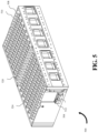
- FIG. 5 is an exemplary embodiment of a battery pack
- FIG. 6 is an exemplary embodiment of a battery management system
- FIG. 7 is a block diagram of an exemplary embodiment of a module monitor unit in one or more aspect of the present disclosure.
- FIG. 8 is a block diagram of another exemplary embodiment a pack monitor unit in one or more aspects of the present disclosure.
- FIG. 9 is an exemplary embodiment of a block diagram of a machine learning model
- FIG. 10 is an exemplary embodiment of a flow diagram for a method of cooling a battery pack of an electric aircraft.
- FIG. 11 is a block diagram of a computing system that may be used with such a system according to an embodiment of the invention.
- aspects of the present disclosure are directed to electric aircraft and methods for cooling a battery pack of an electric aircraft.
- electric aircraft may include weeping wing reservoirs.
- aspects of the present disclosure can be used to cool battery packs of electric aircraft. Aspects of the present disclosure can also be used to provide additional functionality of coolant reservoirs of electric aircraft.
- FIG. 1 illustrates an exemplary embodiment of an electric aircraft 104 .
- Electric aircraft 104 may include, but is not limited to, helicopters, drones, unmanned aerial vehicles (UAV), quadcopters, and the like.
- Electric aircraft 104 may include an electric vertical takeoff and landing (eVTOL) aircraft.
- Electric aircraft 104 may include, but is not limited to, wings, tails, propulsors, hulls, cockpits, rotors, motors, stators, propulsors, landing gears, and the like.
- Electric aircraft 104 may be as described below with reference to FIG. 2 .
- electric aircraft 104 may include consumable coolant reservoir 108 .
- a “consumable coolant reservoir” as used in this disclosure is a fluid containing device that diminishes a level of fluid with use.
- Consumable coolant reservoir 108 may include, but is not limited to, a de-icing system, such as de-icing system 116 .
- Consumable coolant reservoir 108 may include a shape such as, but not limited to, rectangles, squares, circles, ovals, spheres, and the like.
- consumable coolant reservoir 108 may include dimensions such as, but not limited to, heights, widths, thickness, volumes, and the like.
- consumable coolant reservoir 108 may include a 4 ft by 8 ft by 2 ft rectangular structure.
- Consumable coolant reservoir 108 may include one or more impermeable surfaces.
- An “impermeable surface” as used in this disclosure is a structure prohibits a passage of fluid.
- Impermeable surfaces of consumable coolant reservoir 108 may include, but is not limited to, plastics such as polyethylene.
- Consumable coolant reservoir 108 may be configured to contain a fluid, such as coolant 112 .
- a “coolant” as used in this disclosure is a substance that is used to reduce a temperature.
- Coolant 112 may include, but is not limited to, propylene glycol, potassium formate, ethylene glycol, water, ice, dry-ice, and the like.
- Consumable coolant reservoir 108 may be configured to store an amount of coolant 112 in a mass of about 1 Kg to 30 Kg.
- consumable coolant reservoir 108 may be configured to store a volume of coolant 112 in an amount of about 1 gallon to 30 gallons.
- consumable coolant reservoir 108 may include one or more openings. An opening may include, but is not limited to, holes, valves, apertures and the like.
- consumable coolant reservoir 108 may include electromechanical switches, actuators, and the like.
- An opening of consumable coolant reservoir 108 may be configured to adjust a passage of coolant 112 through the opening of consumable coolant reservoir 108 .
- Adjusting a passage may be achieved through electromechanical devices, switches, actuators, valves, and the like. Adjusting a passage may include reducing or increasing a diameter of an opening of consumable coolant reservoir 108 . As a non-limiting example, a passage of consumable coolant reservoir 108 may increase in diameter from 0.25 in. to 0.5 in.
- electric aircraft 104 may include a plurality of consumable coolant reservoirs 108 .
- a plurality of consumable coolant reservoirs 108 may include two or more consumable coolant reservoirs configured to supply coolant 112 to various parts of electric aircraft 104 , such as, but not limited to, wings, tails, battery packs, and the like.
- a consumable coolant reservoir may be connected to battery pack temperature control system 124 .
- a consumable coolant reservoir may be connected to de-icing system 116 . Connections between consumable coolant reservoir 108 and de-icing system 116 and/or battery pack temperature control system 124 may be described below in further detail.
- Consumable coolant reservoir 108 may be configured to fully deplete coolant 112 and/or partially deplete coolant 112 .
- Coolant 112 of consumable coolant reservoir 108 may be drained through via gravity through a valve, outlet, and the like.
- coolant 112 of consumable coolant reservoir 108 may be drained through suction devices, such as vacuums.
- coolant 112 of consumable coolant reservoir 108 may be drained while electric aircraft 104 may be grounded, such as, but not limited to, prior to takeoff.
- a plurality of coolant reservoirs 108 may include backup reservoirs, such as, but not limited to, an emergency de-icing and/or battery cooling reservoir.
- electric aircraft 104 may include de-icing system 116 .
- a “de-icing system” as used in this disclosure is a structure that reduces a buildup of ice of an aircraft.
- De-icing system 116 may include one or more fluidic channels 132 .
- a “fluidic channel” as used in this disclosure is a pathway for liquids and gasses.
- Fluidic channel 132 may include, but is not limited to, pipes, valves, and the like.
- a fluidic channel may include a shape.
- a shape may include a serpentine, straight, curved, or other suitable shapes.
- Fluidic channel 132 may include materials such as, but not limited to, plastics, metals, polymers, composite materials, and the like.
- de-icing system 116 may include a plurality of fluidic channels 132 .
- a plurality of fluidic channels 132 may be configured to distribute coolant 112 throughout electric aircraft 104 .
- de-icing system 116 may be in fluidic communication with consumable coolant reservoir 108 .
- Fluid communication as used in this disclosure is a connection of gases and/or liquids between objects.
- fluidic channel 132 may provide for a fluidic communication between de-icing system 116 and consumable coolant reservoir 108 .
- De-icing system 116 may include one or more pumps, pipes, valves, and the like.
- de-icing system 116 may include piping configured to receive coolant 112 from consumable coolant reservoir 112 .
- De-icing system 116 may include piping configured to deliver coolant 112 to various parts of electric aircraft 104 , such as wing 120 .
- coolant 112 may be consumed through de-icing system 116 .
- a consuming of coolant 112 may include depleting consumable coolant reservoir 108 of coolant 112 .
- De-icing system 116 may be configured to outlet coolant 112 proximal a leading edge of wing 120 .
- Wing 120 may include a wing as described below with reference to FIG. 2 .
- de-icing system 116 may include one or more pumps or other pressure inducing elements. De-icing system 116 may utilize one or more pumps to deliver coolant 112 proximal a leading edge of wing 120 . In some embodiments, de-icing system 116 may be configured to force coolant 112 through ducts, holes, and/or other porous materials to an exterior of wing 120 . In some embodiments, de-icing system 116 may include nozzles and/or discharge pipes that may be placed on various exterior parts of electric aircraft 104 . As a non-limiting example, a discharge pipe may be placed on a propulsor of electric aircraft 104 .
- a discharge pipe may be configured to release coolant 112 onto a propulsor of electric aircraft 104 .
- de-icing system 116 may include a weeping wing de-icing system. Coolant 112 may be configured to prevent a freezing of and/or help de-ice wing 120 .
- de-icing system 116 may include at least a processor and a memory communicatively connected to the at least a processor. A memory may contain instructions configuring at least a processor to perform various tasks. De-icing system 116 may be configured to automate a distribution of coolant 112 through electric aircraft 104 . In some embodiments, de-icing system 116 may be configured to determine a wing parameter of wing 120 .
- a “wing parameter” as used in this disclosure is a metric pertaining to a wing of an aircraft.
- a wing parameter may include, but is not limited to, wing friction, wing lift, wing rag, wing temperature, and the like.
- De-icing system 116 may determine a wing parameter as a function of received wing data from one or more sensors. Sensors may include, but are not limited to, thermometers, thermocouples, thermistors, humidity sensors, wind speed sensors, altimeters, and the like. Sensors may be described in further detail below with reference to FIG. 4 .
- “Wing data” as used in this disclosure is information pertaining to a wing of an aircraft.
- De-icing system 116 may be configured to adjust a dispersal of coolant 112 from consumable coolant reservoir 108 as a function of a determined wing parameter. In some embodiments, de-icing system 116 may compare a wing parameter to a wing parameter threshold.
- a “wing parameter threshold” as used in this disclosure is a value that if reached changes a system.
- a wing parameter threshold may include, but is not limited to, temperatures, friction values, wind speeds, altitudes, lifts, drags, and the like.
- De-icing system 116 may receive a wing parameter threshold from user input, an external computing device, and/or previous iterations of processing. In some embodiments, de-icing system 116 may utilize a de-icing machine learning model.
- a de-icing machine learning model may be trained with training data correlating wing parameters to de-icing functions. Training data may be received from user input, external computing devices, and/or previous iterations of processing.
- a de-icing machine learning model may be configured to input wing parameters and output deicing functions, such as coolant amounts, coolant dispersal rates, types of coolant, and the like.
- electric aircraft 104 may include battery pack temperature control system 124 .
- a “battery pack temperature control system” as used in this disclosure is a structure configured to manage thermal energy of one or more battery packs.
- Battery pack temperature control system 124 may include one or more thermal conduits.
- a “thermal conduit” as used in this disclosure is a structure that conducts thermal energy.
- a thermal conduit may include, but is not limited to, pipes, vents, fans, heat sinks, and the like.
- battery pack temperature control system 124 may be in thermal communication with consumable coolant reservoir 108 and/or de-icing system 116 .
- “Thermal communication” as used in this disclosure is a form of connection between objects through thermal energy.
- Thermal connection may be achieved through thermal conduits or other heat exchanging devices.
- thermal communication may include thermal pathway 136 .
- a “thermal pathway” as used in this disclosure is a structure directing a flow of heat energy.
- Thermal pathway 136 may include thermal conduits such as, but not limited to, pipes, vents, fans, and the like.
- battery pack temperature control system 124 may be configured to direct heat away from battery pack 128 .
- a battery pack may be as described below with reference to FIG. 5 .
- Battery pack temperature control system 124 may include one or more sensors, such as, but not limited to, thermometers, voltmeters, ohmmeters, ammeters, pressure sensors, and the like. Sensors may be as described below with reference to FIG. 4 .
- battery pack temperature control system 124 may be configured to control or otherwise maintain a temperature of battery pack 128 .
- Battery pack temperature control system 124 may include a processor and a memory communicatively connected to the processor.
- a memory may contain instructions configuring a processor of battery pack temperature control system 124 to perform various tasks.
- battery pack temperature control system 124 may be configured to determine a battery parameter of battery pack 128 .
- a battery parameter may be determined as a function of received battery data of one or more sensors. Sensors may include, but are not limited to, voltmeters, ohmmeters, thermometers, and the like.
- a “battery parameter” as used in this disclosure is a metric relating to a battery.
- a battery parameter may include, but is not limited to, voltages, temperatures, resistances, capacities, currents, power output, state of charge, state of health, and the like.
- Battery data as used in this disclosure is information pertaining to a battery. Battery data may include, but is not limited to, voltages, temperatures, resistances, capacities, currents, and the like.
- Battery pack temperature control system 124 may be configured to reduce a thermal energy of battery pack 128 as a function of a determined battery parameter.
- Battery pack temperature control system 124 may be configured to determine a thermal energy management plan as a function of a battery parameter.
- a “thermal energy management plan” as used in this disclosure is one or more actions that controls a temperature of an object.
- Battery pack temperature control system 124 may be configured to generate a thermal energy management plan as a function of an optimization model, as described below.
- a thermal energy management plan may include passing coolant 112 through a thermal conduit, such as heat exchanger 140 , near battery pack 128 .
- Battery pack temperature control system 124 may reduce a thermal energy of battery pack 128 through a passage of coolant 112 to battery pack 128 .
- battery pack temperature control system 124 may adjust a thermal conduit such as, but not limited to, a pipe and/or valve of thermal pathway 136 which may allow a passage of coolant 112 through thermal pathway 136 to battery pack 128 .
- battery pack temperature control system 124 may be configured to direct coolant 112 through thermal pathway 136 to pass near and/or around battery pack 128 .
- battery pack temperature control system 124 may include battery coolant 144 .
- Battery coolant 144 may include a coolant such as coolant 112 .
- battery pack temperature control system 124 may utilize battery coolant 144 to maintain a thermal energy of battery pack 128 .
- Battery pack temperature control system 124 may utilize a battery temperature machine learning model.
- a battery temperature machine learning model may be trained with training data correlating battery parameters to temperature control functions. Training data may be received from user input, external computing devices, and/or previous iterations of processing.
- a battery temperature machine learning model may be configured to input battery parameters and output battery temperature control functions such as, but not limited to, venting heated air, directing coolant, and the like.
- battery pack temperature control system 124 may be configured to cool down battery pack 128 through apparatuses and methods as described in U.S. patent application Ser. No. 17/665,454, filed Feb. 4, 2022, and titled “AN APPRARTUS FOR A GROUND-BASED BATTERY MANAGEMENT FOR AN ELECTRIC AIRCRAFT”, and/or in U.S. patent application Ser. No. 17/563,383, filed Dec. 28, 2021, and titled “SYSTEM FOR BATTERY TEMPERATURE MANAGEMENT IN AN ELECTRIC AIRCRAFT”, both of which are incorporated by reference herein in their entirety.
- de-icing system 116 may include heat exchanger 140 .
- a “heat exchanger” as used in this disclosure is an object that transfers heat between two structures.
- Heat exchanger 140 may include, but is not limited to, shell and tube heat exchangers, plate heat exchangers, plate and shell heat exchangers, adiabatic wheel heat exchangers, plate fin heat exchangers, finned tube heat exchangers, pillow plate heat exchangers, waste heat recovery units, dynamic scraped surface heat exchangers, phase-change heat exchangers, direct contact heat exchangers, microchannel heat exchangers, HVAC and refrigeration air coils, helical-coil heat exchangers, spiral heat exchangers, and the like.
- Heat exchanger 140 of de-icing system 116 may allow for a use of coolant 112 without depleting coolant 112 from consumable coolant reservoir 108 .
- Coolant 112 may flow through thermal pathway 136 to battery pack temperature control system 124 .
- Battery pack temperature control system 124 may reduce a thermal energy of battery pack 128 through exchanging heat energy between battery pack 128 and coolant 112 .
- Coolant 112 may become heated through an exchange of heat with battery pack 128 .
- De-icing system 116 may direct heated coolant 112 from battery pack temperature control system 124 to heat exchanger 140 .
- Heat exchanger 140 may be placed near wing 120 .
- De-icing system 116 may transfer heated coolant 112 to heat exchanger 140 placed by wing 120 which may allow for a de-icing of wing 120 . Coolant 112 may become colder as heat may be exchanged through heat exchanger 140 by wing 120 . De-icing system 116 may loop coolant 112 back to consumable coolant reservoir 108 , where coolant 112 may be used again by battery pack temperature control system 124 to reduce a thermal energy of battery pack 128 . De-icing system 116 may indirectly pass coolant through battery pack temperature control system 124 through heat exchanger 140 . In other embodiments, de-icing system 116 may be in fluidic communication with battery pack temperature control system 124 .
- Battery pack temperature control system 124 may reduce a thermal energy of battery pack 128 until it reaches an acceptable temperature.
- An acceptable temperature may be received from user input, external computing devices, and/or determined from previous iterations of processing.
- de-icing system 116 and battery pack temperature control system 124 may adjust thermal pathway 136 and/or fluidic channel 132 as a function of wing parameters and/or battery parameters.
- wing 120 may not need coolant 112
- battery pack 128 may need coolant 112 to reduce a thermal energy.
- wing 120 may require coolant 112 to de-ice, while battery pack 128 may maintain acceptable temperatures.
- battery pack temperature control system 124 may be configured to generate an objective function.
- An “objective function” as used in this disclosure is a process of minimizing or maximizing one or more values based on a set of constraints.
- Battery pack temperature control system 124 may generate an objective function to optimize a cooling of battery pack 128 .
- an objective function of battery pack temperature control system 124 may include an optimization criterion.
- An optimization criterion may include any description of a desired value or range of values for one or more attributes of a battery pack; desired value or range of values may include a maximal or minimal value, a range between maximal or minimal values, or an instruction to maximize or minimize an attribute.
- an optimization criterion may specify that a temperature should be within a 5% difference of a temperature criterion; an optimization criterion may cap a value of a temperature of a battery pack, for instance specifying that battery pack must not exceed temperatures greater than a specified value. An optimization criterion may alternatively request that a temperature of a battery pack be greater than a certain value. An optimization criterion may specify one or more tolerances for precision in cooling a battery pack. An optimization criterion may specify one or more desired cooling criteria for a cooling process. In an embodiment, an optimization criterion may assign weights to different battery parameters or values associated with battery parameters.
- minimization of temperature may be multiplied by a first weight, while tolerance above a certain value may be multiplied by a second weight.
- Optimization criteria may be combined in weighted or unweighted combinations into a function reflecting an overall outcome desired by a user; a function may be a battery parameter function to be minimized and/or maximized.
- a function may be defined by reference to attribute data table criteria constraints and/or weighted aggregation thereof as provided by battery pack temperature control system 124 ; for instance, a battery cooling function ⁇ mbining optimization criteria may seek to minimize or maximize a function of a battery cooling process.
- battery pack temperature control system 124 may use an objective function to compare battery parameters with cooling criterion.
- Generation of an objective function may include generation of a function to score and weight factors to achieve a process score for each feasible pairing.
- pairings may be scored in a matrix for optimization, where columns represent battery parameters and rows represent cooling processes potentially paired therewith; each cell of such a matrix may represent a score of a pairing of the corresponding battery parameter to the corresponding cooling process.
- assigning a predicted process that optimizes the objective function includes performing a greedy algorithm process.
- a “greedy algorithm” is defined as an algorithm that selects locally optimal choices, which may or may not generate a globally optimal solution.
- battery pack temperature control system 124 may select pairings so that scores associated therewith are the best score for each battery parameter and/or for each battery cooling criterion.
- optimization may determine the combination of battery parameters such that each cooling process pairing includes the highest score possible.
- an objective function may be formulated as a linear objective function.
- Battery pack temperature control system 124 may solve an objective function using a linear program such as without limitation a mixed-integer program.
- a “linear program,” as used in this disclosure, is a program that optimizes a linear objective function, given at least a constraint.
- objective function may seek to maximize a total score ⁇ r ⁇ R ⁇ s ⁇ S c rs x rs , where R is a set of all battery parameters r, S is a set of all cooling processes s, c rs is a score of a pairing of a given battery parameter with a given process, and x rs is 1 if a battery parameter r is paired with a cooling process s, and 0 otherwise.
- constraints may specify that each battery parameter is assigned to only one cooling process, and each cooling process is assigned only one battery parameter. Cooling processes may include cooling processes as described above. Sets of battery parameters may be optimized for a maximum score combination of all generated battery parameters.
- battery pack temperature control system 124 may determine a combination of battery parameters that maximizes a total score subject to a constraint that all battery parameters are paired to exactly one cooling process. Not all cooling processes may receive a battery parameter pairing since each cooling process may only produce one battery parameter.
- an objective function may be formulated as a mixed integer optimization function.
- a “mixed integer optimization” as used in this disclosure is a program in which some or all of the variables are restricted to be integers.
- a mathematical solver may be implemented to solve for the set of feasible pairings that maximizes the sum of scores across all pairings; mathematical solver may be implemented on battery pack temperature control system 124 , another device, and/or may be implemented on third-party solver.
- optimizing an objective function may include minimizing a loss function, where a “loss function” is an expression an output of which an optimization algorithm minimizes to generate an optimal result.
- battery pack temperature control system 124 may assign variables relating to a set of parameters, which may correspond to score battery parameters as described above, calculate an output of mathematical expression using the variables, and select a pairing that produces an output having the lowest size, according to a given definition of “size,” of the set of outputs representing each of cooling process combinations; size may, for instance, included absolute value, numerical size, or the like. Selection of different loss functions may result in identification of different potential pairings as generating minimal outputs.
- Objectives represented in an objective function and/or loss function may include minimization of battery temperature. Objectives may include minimization of coolant required. Objectives may include minimization of cool down time.
- a fuzzy logic comparison may include a first fuzzy set.
- a first fuzzy set may be represented, without limitation, according to a first membership function representing a probability that an input falling on a first range of values is a member of the first fuzzy set, where the first membership function has values on a range of probabilities such as without limitation the interval [0,1], and an area beneath the first membership function may represent a set of values within first fuzzy set.
- a first range of values may be defined on two or more dimensions, representing, for instance, a Cartesian product between a plurality of ranges, curves, axes, spaces, dimensions, or the like.
- a first membership function may include any suitable function mapping a first range to a probability interval, including without limitation a triangular function defined by two linear elements such as line segments or planes that intersect at or below the top of the probability interval.
- triangular membership function may be defined as:
- y ⁇ ( x , a , b , c ) ⁇ 0 , for ⁇ x > c ⁇ and ⁇ ⁇ x ⁇ a x - a b - a , for ⁇ a ⁇ x ⁇ b c - x c - b , if ⁇ b ⁇ x ⁇ c a trapezoidal membership function may be defined as:
- y ⁇ ( x , a , b , c , d ) max ⁇ ( min ( x - a b - a , 1 , d - x d - c ) , 0 )
- a sigmoidal function may be defined as:
- y ⁇ ( x , a , c ) 1 1 - e - a ⁇ ( x - c )
- a Gaussian membership function may be defined as:
- y ⁇ ( x , c , ⁇ ) e - 1 2 ⁇ ( x - c ⁇ ) 2 and a bell membership function may be defined as:
- a first fuzzy set may represent any value or combination of values as described above, including battery parameters, wing parameters, any resource datum, any niche datum, and/or any combination of the above.
- a second fuzzy set which may represent any value which may be represented by first fuzzy set, may be defined by a second membership function on a second range; a second range may be identical and/or overlap with a first range and/or may be combined with first range via Cartesian product or the like to generate a mapping permitting evaluation overlap of a first fuzzy set and a second fuzzy set.
- first fuzzy set and second fuzzy set have a region that overlaps
- a first membership function and a second membership function may intersect at a point representing a probability, as defined on probability interval, of a match between a first fuzzy set and a second fuzzy set.
- a single value of a first and/or a second fuzzy set may be located at a locus on a first range and/or a second range, where a probability of membership may be taken by evaluation of a first membership function and/or a second membership function at that range point.
- a probability may be compared to a threshold to determine whether a positive match is indicated.
- a threshold may, in a non-limiting example, represent a degree of match between a first fuzzy set and a second fuzzy set, and/or single values therein with each other or with either set, which is sufficient for purposes of the matching process; for instance, threshold may indicate a sufficient degree of overlap between probabilistic outcomes and/or predictive prevalence values for combination to occur as described above. There may be multiple thresholds; for instance, a second threshold may indicate a sufficient match for purposes of a pooling threshold as described in this disclosure. Each threshold may be established by one or more user inputs. Alternatively or additionally, each threshold may be tuned by a machine-learning and/or statistical process, for instance and without limitation as described in further detail below.
- a degree of match between fuzzy sets may be used to rank one battery parameter datum against another. For instance, if two battery parameter datums have fuzzy sets matching a probabilistic outcome fuzzy set by having a degree of overlap exceeding a threshold, battery pack temperature control system 124 may further rank the two battery parameter datums by ranking a battery parameter datum having a higher degree of match more highly than a battery parameter datum having a lower degree of match.
- Battery pack temperature control system 124 may use fuzzy logic to classify and/or group two or more data entries.
- battery pack temperature control system 124 may determine, using fuzzy logic, inputs from as “high temperature” and “high coolant levels” and output “battery pack ready for coolant”.
- battery pack temperature control system 124 may determine inputs as “low coolant levels” and “normal battery temperatures” and output “no action required for battery pack”.
- Electric aircraft 200 may include any of the aircrafts as disclosed herein including electric aircraft 104 of FIG. 1 .
- electric aircraft 200 may be an electric vertical takeoff and landing (eVTOL) aircraft.
- eVTOL electric vertical takeoff and landing
- an “aircraft” is any vehicle that may fly by gaining support from the air.
- aircraft may include airplanes, helicopters, commercial, personal and/or recreational aircrafts, instrument flight aircrafts, drones, electric aircrafts, airliners, rotorcrafts, vertical takeoff and landing aircrafts, jets, airships, blimps, gliders, paramotors, quad-copters, unmanned aerial vehicles (UAVs) and the like.
- an “electric aircraft” is an electrically powered aircraft such as one powered by one or more electric motors or the like.
- electrically powered (or electric) aircraft may be an electric vertical takeoff and landing (eVTOL) aircraft.
- Electric aircraft 200 may be capable of rotor-based cruising flight, rotor-based takeoff, rotor-based landing, fixed-wing cruising flight, airplane-style takeoff, airplane-style landing, and/or any combination thereof.
- Electric aircraft 200 may include one or more manned and/or unmanned aircrafts.
- Electric aircraft 200 may include one or more all-electric short takeoff and landing (eSTOL) aircrafts.
- eSTOL aircrafts may accelerate the plane to a flight speed on takeoff and decelerate the plane after landing.
- electric aircraft may be configured with an electric propulsion assembly. Including one or more propulsion and/or flight components.
- Electric propulsion assembly may include any electric propulsion assembly (or system) as described in U.S. Nonprovisional application Ser. No. 16/703,225, filed on Dec. 4, 2019, and entitled “AN INTEGRATED ELECTRIC PROPULSION ASSEMBLY,” the entirety of which is incorporated herein by reference.
- a “vertical take-off and landing (VTOL) aircraft” is one that can hover, take off, and land vertically.
- An “electric vertical takeoff and landing aircraft” or “eVTOL aircraft”, as used in this disclosure, is an electrically powered aircraft typically using an energy source, of a plurality of energy sources to power the aircraft.
- eVTOL may be capable of rotor-based cruising flight, rotor-based takeoff, rotor-based landing, fixed-wing cruising flight, airplane-style takeoff, airplane style landing, and/or any combination thereof.
- Rotor-based flight is where the aircraft generates lift and propulsion by way of one or more powered rotors or blades coupled with an engine, such as a “quad copter,” multi-rotor helicopter, or other vehicle that maintains its lift primarily using downward thrusting propulsors.
- “Fixed-wing flight”, as described herein, is where the aircraft is capable of flight using wings and/or foils that generate lift caused by the aircraft's forward airspeed and the shape of the wings and/or foils, such as airplane-style flight.
- electric aircraft 200 may generally include a fuselage 204 , a flight component 208 (or a plurality of flight components 208 ), a pilot control 220 , an aircraft sensor 228 (or a plurality of aircraft sensors 228 ) and flight controller 124 .
- flight components 208 may include at least a lift component 212 (or a plurality of lift components 212 ) and at least a pusher component 216 (or a plurality of pusher components 216 ).
- Aircraft sensor(s) 228 may be the same as or similar to aircraft sensor(s) 160 of FIG. 1 .
- Fuselage is the main body of an aircraft, or in other words, the entirety of the aircraft except for the cockpit, nose, wings, empennage, nacelles, any and all control surfaces, and generally contains an aircraft's payload.
- Fuselage 204 may include structural elements that physically support a shape and structure of an aircraft. Structural elements may take a plurality of forms, alone or in combination with other types. Structural elements may vary depending on a construction type of aircraft such as without limitation a fuselage 204 .
- Fuselage 204 may comprise a truss structure. A truss structure may be used with a lightweight aircraft and comprises welded steel tube trusses.
- a “truss,” as used in this disclosure, is an assembly of beams that create a rigid structure, often in combinations of triangles to create three-dimensional shapes.
- a truss structure may alternatively comprise wood construction in place of steel tubes, or a combination thereof.
- structural elements may comprise steel tubes and/or wood beams.
- structural elements may include an aircraft skin. Aircraft skin may be layered over the body shape constructed by trusses. Aircraft skin may comprise a plurality of materials such as plywood sheets, aluminum, fiberglass, and/or carbon fiber.
- fuselage 204 may be configurable based on the needs of the aircraft per specific mission or objective. The general arrangement of components, structural elements, and hardware associated with storing and/or moving a payload may be added or removed from fuselage 204 as needed, whether it is stowed manually, automatedly, or removed by personnel altogether. Fuselage 204 may be configurable for a plurality of storage options. Bulkheads and dividers may be installed and uninstalled as needed, as well as longitudinal dividers where necessary.
- Bulkheads and dividers may be installed using integrated slots and hooks, tabs, boss and channel, or hardware like bolts, nuts, screws, nails, clips, pins, and/or dowels, to name a few.
- Fuselage 204 may also be configurable to accept certain specific cargo containers, or a receptable that can, in turn, accept certain cargo containers.
- electric aircraft 200 may include a plurality of laterally extending elements attached to fuselage 204 .
- a “laterally extending element” is an element that projects essentially horizontally from fuselage, including an outrigger, a spar, and/or a fixed wing that extends from fuselage.
- Wings may be structures which include airfoils configured to create a pressure differential resulting in lift. Wings may generally dispose on the left and right sides of the aircraft symmetrically, at a point between nose and empennage. Wings may comprise a plurality of geometries in planform view, swept swing, tapered, variable wing, triangular, oblong, elliptical, square, among others.
- a wing's cross section geometry may comprise an airfoil.
- An “airfoil” as used in this disclosure is a shape specifically designed such that a fluid flowing above and below it exert differing levels of pressure against the top and bottom surface.
- the bottom surface of an aircraft can be configured to generate a greater pressure than does the top, resulting in lift.
- Laterally extending element may comprise differing and/or similar cross-sectional geometries over its cord length or the length from wing tip to where wing meets the aircraft's body.
- One or more wings may be symmetrical about the aircraft's longitudinal plane, which comprises the longitudinal or roll axis reaching down the center of the aircraft through the nose and empennage, and the plane's yaw axis.
- Laterally extending element may comprise controls surfaces configured to be commanded by a pilot or pilots to change a wing's geometry and therefore its interaction with a fluid medium, like air.
- Control surfaces may comprise flaps, ailerons, tabs, spoilers, and slats, among others.
- the control surfaces may dispose on the wings in a plurality of locations and arrangements and in embodiments may be disposed at the leading and trailing edges of the wings, and may be configured to deflect up, down, forward, aft, or a combination thereof.
- An aircraft, including a dual-mode aircraft may comprise a combination of control surfaces to perform maneuvers while flying or on ground.
- winglets may be provided at terminal ends of the wings which can provide improved aerodynamic efficiency and stability in certain flight situations.
- the wings may be foldable to provide a compact aircraft profile, for example, for storage, parking and/or in certain flight modes.
- electric aircraft 200 may include a plurality of flight components 208 .
- a “flight component” is a component that promotes flight and guidance of an aircraft.
- Flight component 208 may include power sources, control links to one or more elements, fuses, and/or mechanical couplings used to drive and/or control any other flight component.
- Flight component 208 may include a motor that operates to move one or more flight control components, to drive one or more propulsors, or the like.
- a motor may be driven by direct current (DC) electric power and may include, without limitation, brushless DC electric motors, switched reluctance motors, induction motors, or any combination thereof.
- DC direct current
- Flight component 208 may include an energy source.
- An energy source may include, for example, a generator, a photovoltaic device, a fuel cell such as a hydrogen fuel cell, direct methanol fuel cell, and/or solid oxide fuel cell, an electric energy storage device (e.g. a capacitor, an inductor, and/or a battery).
- An energy source may also include a battery cell, or a plurality of battery cells connected in series into a module and each module connected in series or in parallel with other modules. Configuration of an energy source containing connected modules may be designed to meet an energy or power requirement and may be designed to fit within a designated footprint in an electric aircraft.
- flight component 208 may be mechanically coupled to an aircraft.
- mechanically coupled to mean that at least a portion of a device, component, or circuit is connected to at least a portion of the aircraft via a mechanical coupling.
- Said mechanical coupling can include, for example, rigid coupling, such as beam coupling, bellows coupling, bushed pin coupling, constant velocity, split-muff coupling, diaphragm coupling, disc coupling, donut coupling, elastic coupling, flexible coupling, fluid coupling, gear coupling, grid coupling, hirth joints, hydrodynamic coupling, jaw coupling, magnetic coupling, Oldham coupling, sleeve coupling, tapered shaft lock, twin spring coupling, rag joint coupling, universal joints, or any combination thereof.
- mechanical coupling may be used to connect the ends of adjacent parts and/or objects of an electric aircraft. Further, in an embodiment, mechanical coupling may be used to join two pieces of rotating electric aircraft components.
- plurality of flight components 208 of aircraft 200 may include at least a lift component 212 and at least a pusher component 216 .
- Flight component 208 may include a propulsor, a propeller, a motor, rotor, a rotating element, electrical energy source, battery, and the like, among others. Each flight component may be configured to generate lift and flight of electric aircraft.
- flight component 208 may include one or more lift components 212 , one or more pusher components 216 , one or more battery packs including one or more batteries or cells, and one or more electric motors. Flight component 208 may include a propulsor.
- a “propulsor component” or “propulsor” is a component and/or device used to propel a craft by exerting force on a fluid medium, which may include a gaseous medium such as air or a liquid medium such as water.
- a propulsor when a propulsor twists and pulls air behind it, it may, at the same time, push an aircraft forward with an amount of force and/or thrust. More air pulled behind an aircraft results in greater thrust with which the aircraft is pushed forward.
- Propulsor component may include any device or component that consumes electrical power on demand to propel an electric aircraft in a direction or other vehicle while on ground or in-flight.
- lift component 212 may include a propulsor, a propeller, a blade, a motor, a rotor, a rotating element, an aileron, a rudder, arrangements thereof, combinations thereof, and the like.
- Each lift component 212 when a plurality is present, of plurality of flight components 208 is configured to produce, in an embodiment, substantially upward and/or vertical thrust such that aircraft moves upward.
- a “lift component” is a component and/or device used to propel a craft upward by exerting downward force on a fluid medium, which may include a gaseous medium such as air or a liquid medium such as water.
- Lift component 212 may include any device or component that consumes electrical power on demand to propel an electric aircraft in a direction or other vehicle while on ground or in-flight.
- lift component 212 may include a rotor, propeller, paddle wheel and the like thereof, wherein a rotor is a component that produces torque along the longitudinal axis, and a propeller produces torque along the vertical axis.
- lift component 212 includes a plurality of blades.
- a “blade” is a propeller that converts rotary motion from an engine or other power source into a swirling slipstream.
- blade may convert rotary motion to push the propeller forwards or backwards.
- lift component 212 may include a rotating power-driven hub, to which are attached several radial airfoil-section blades such that the whole assembly rotates about a longitudinal axis.
- Blades may be configured at an angle of attack.
- angle of attack may include a fixed angle of attack.
- a “fixed angle of attack” is fixed angle between a chord line of a blade and relative wind.
- a “fixed angle” is an angle that is secured and/or unmovable from the attachment point.
- angle of attack may include a variable angle of attack.
- a “variable angle of attack” is a variable and/or moveable angle between a chord line of a blade and relative wind.
- a “variable angle” is an angle that is moveable from an attachment point.
- angle of attack be configured to produce a fixed pitch angle.
- a “fixed pitch angle” is a fixed angle between a cord line of a blade and the rotational velocity direction. In an embodiment fixed angle of attack may be manually variable to a few set positions to adjust one or more lifts of the aircraft prior to flight.
- blades for an aircraft are designed to be fixed to their hub at an angle similar to the thread on a screw makes an angle to the shaft; this angle may be referred to as a pitch or pitch angle which will determine a speed of forward movement as the blade rotates.
- lift component 212 may be configured to produce a lift.
- a “lift” is a perpendicular force to the oncoming flow direction of fluid surrounding the surface.
- relative air speed may be horizontal to the aircraft, wherein lift force may be a force exerted in a vertical direction, directing the aircraft upwards.
- lift component 212 may produce lift as a function of applying a torque to lift component.
- a “torque” is a measure of force that causes an object to rotate about an axis in a direction.
- torque may rotate an aileron and/or rudder to generate a force that may adjust and/or affect altitude, airspeed velocity, groundspeed velocity, direction during flight, and/or thrust.
- flight components 208 such as a power source(s) may apply a torque on lift component 212 to produce lift.
- a plurality of lift components 212 of plurality of flight components 208 may be arranged in a quad copter orientation.
- a “quad copter orientation” is at least a lift component oriented in a geometric shape and/or pattern, wherein each of the lift components is located along a vertex of the geometric shape.
- a square quad copter orientation may have four lift propulsor components oriented in the geometric shape of a square, wherein each of the four lift propulsor components are located along the four vertices of the square shape.
- a hexagonal quad copter orientation may have six lift components oriented in the geometric shape of a hexagon, wherein each of the six lift components are located along the six vertices of the hexagon shape.
- quad copter orientation may include a first set of lift components and a second set of lift components, wherein the first set of lift components and the second set of lift components may include two lift components each, wherein the first set of lift components and a second set of lift components are distinct from one another.
- the first set of lift components may include two lift components that rotate in a clockwise direction
- the second set of lift propulsor components may include two lift components that rotate in a counterclockwise direction.
- the first set of lift components may be oriented along a line oriented 45° from the longitudinal axis of aircraft 200 .
- the second set of lift components may be oriented along a line oriented 135° from the longitudinal axis, wherein the first set of lift components line and the second set of lift components are perpendicular to each other.
- pusher component 216 and lift component 212 may include any such components and related devices as disclosed in U.S. Nonprovisional application Ser. No. 16/427,298, filed on May 30, 2019, entitled “SELECTIVELY DEPLOYABLE HEATED PROPULSOR SYSTEM,”, U.S. Nonprovisional application Ser. No. 16/703,225, filed on Dec. 4, 2019, entitled “AN INTEGRATED ELECTRIC PROPULSION ASSEMBLY,”, U.S. Nonprovisional application Ser. No. 16/910,255, filed on Jun. 24, 2020, entitled “AN INTEGRATED ELECTRIC PROPULSION ASSEMBLY,”, U.S.
- pusher component 216 may include a propulsor, a propeller, a blade, a motor, a rotor, a rotating element, an aileron, a rudder, arrangements thereof, combinations thereof, and the like.
- Each pusher component 216 when a plurality is present, of the plurality of flight components 208 is configured to produce, in an embodiment, substantially forward and/or horizontal thrust such that the aircraft moves forward.
- a “pusher component” is a component that pushes and/or thrusts an aircraft through a medium.
- pusher component 216 may include a pusher propeller, a paddle wheel, a pusher motor, a pusher propulsor, and the like. Additionally, or alternatively, pusher flight component may include a plurality of pusher flight components.
- Pusher component 216 is configured to produce a forward thrust.
- forward thrust may include a force to force aircraft to in a horizontal direction along the longitudinal axis.
- pusher component 216 may twist and/or rotate to pull air behind it and, at the same time, push aircraft 200 forward with an equal amount of force.
- the more air forced behind aircraft the greater the thrust force with which the aircraft is pushed horizontally will be.
- forward thrust may force aircraft 200 through the medium of relative air.
- plurality of flight components 208 may include one or more puller components.
- a “puller component” is a component that pulls and/or tows an aircraft through a medium.
- puller component may include a flight component such as a puller propeller, a puller motor, a tractor propeller, a puller propulsor, and the like. Additionally, or alternatively, puller component may include a plurality of puller flight components.
- a “power source” is a source that powers, drives and/or controls any flight component and/or other aircraft component.
- power source may include a motor that operates to move one or more lift components 212 and/or one or more pusher components 216 , to drive one or more blades, or the like thereof.
- Motor(s) may be driven by direct current (DC) electric power and may include, without limitation, brushless DC electric motors, switched reluctance motors, induction motors, or any combination thereof.
- Motor(s) may also include electronic speed controllers or other components for regulating motor speed, rotation direction, and/or dynamic braking.
- a “motor” as used in this disclosure is any machine that converts non-mechanical energy into mechanical energy.
- An “electric motor” as used in this disclosure is any machine that converts electrical energy into mechanical energy.
- aircraft 200 may include a pilot control 220 .
- a “pilot control” is a mechanism or means which allows a pilot to monitor and control operation of aircraft such as its flight components (for example, and without limitation, pusher component, lift component and other components such as propulsion components).
- pilot control 220 may include a collective, inceptor, foot bake, steering and/or control wheel, control stick, pedals, throttle levers, and the like.
- Pilot control 220 may be configured to translate a pilot's desired torque for each flight component of the plurality of flight components, such as and without limitation, pusher component 216 and lift component 212 .
- Pilot control 220 may be configured to control, via inputs and/or signals such as from a pilot, the pitch, roll, and yaw of the aircraft. Pilot control may be available onboard aircraft or remotely located from it, as needed or desired.
- a “collective control” or “collective” is a mechanical control of an aircraft that allows a pilot to adjust and/or control the pitch angle of plurality of flight components 208 .
- collective control may alter and/or adjust the pitch angle of all of the main rotor blades collectively.
- pilot control 220 may include a yoke control.
- a “yoke control” is a mechanical control of an aircraft to control the pitch and/or roll.
- yoke control may alter and/or adjust the roll angle of aircraft 200 as a function of controlling and/or maneuvering ailerons.
- pilot control 220 may include one or more foot-brakes, control sticks, pedals, throttle levels, and the like thereof.
- pilot control 220 may be configured to control a principal axis of the aircraft.
- a “principal axis” is an axis in a body representing one three dimensional orientations.
- Principal axis may include a yaw axis.
- yaw axis is an axis that is directed towards the bottom of aircraft, perpendicular to the wings.
- a positive yawing motion may include adjusting and/or shifting nose of aircraft 200 to the right.
- Principal axis may include a pitch axis.
- a “pitch axis” is an axis that is directed towards the right laterally extending wing of aircraft.
- a positive pitching motion may include adjusting and/or shifting nose of aircraft 200 upwards.
- Principal axis may include a roll axis.
- a “roll axis” is an axis that is directed longitudinally towards nose of aircraft, parallel to fuselage.
- a positive rolling motion may include lifting the left and lowering the right wing concurrently.
- Pilot control 220 may be configured to modify a variable pitch angle.
- pilot control 220 may adjust one or more angles of attack of a propulsor or propeller.
- aircraft 200 may include at least an aircraft sensor 228 .
- Aircraft sensor 228 may include any sensor or noise monitoring circuit described in this disclosure. Aircraft sensor 228 , in some embodiments, may be communicatively connected or coupled to flight controller 124 . Aircraft sensor 228 may be configured to sense a characteristic of pilot control 220 . Sensor may be a device, module, and/or subsystem, utilizing any hardware, software, and/or any combination thereof to sense a characteristic and/or changes thereof, in an instant environment, for instance without limitation a pilot control 220 , which the sensor is proximal to or otherwise in a sensed communication with, and transmit information associated with the characteristic, for instance without limitation digitized data.
- Sensor 228 may be mechanically and/or communicatively coupled to aircraft 200 , including, for instance, to at least a pilot control 220 .
- Aircraft sensor 228 may be configured to sense a characteristic associated with at least a pilot control 220 .
- An environmental sensor may include without limitation one or more sensors used to detect ambient temperature, barometric pressure, and/or air velocity.
- Aircraft sensor 228 may include without limitation gyroscopes, accelerometers, inertial measurement unit (IMU), and/or magnetic sensors, one or more humidity sensors, one or more oxygen sensors, or the like. Additionally or alternatively, sensor 228 may include at least a geospatial sensor.
- Aircraft sensor 228 may be located inside aircraft, and/or be included in and/or attached to at least a portion of aircraft.
- Sensor may include one or more proximity sensors, displacement sensors, vibration sensors, and the like thereof. Sensor may be used to monitor the status of aircraft 200 for both critical and non-critical functions. Sensor may be incorporated into vehicle or aircraft or be remote.
- aircraft sensor 228 may be configured to sense a characteristic associated with any pilot control described in this disclosure.
- aircraft sensor 228 may include an inertial measurement unit (IMU), an accelerometer, a gyroscope, a proximity sensor, a pressure sensor, a light sensor, a pitot tube, an air speed sensor, a position sensor, a speed sensor, a switch, a thermometer, a strain gauge, an acoustic sensor, and an electrical sensor.
- IMU inertial measurement unit
- aircraft sensor 228 may sense a characteristic as an analog measurement, for instance, yielding a continuously variable electrical potential indicative of the sensed characteristic.
- aircraft sensor 228 may additionally comprise an analog to digital converter (ADC) as well as any additionally circuitry, such as without limitation a Wheatstone bridge, an amplifier, a filter, and the like.
- ADC analog to digital converter
- aircraft sensor 228 may comprise a strain gage configured to determine loading of one or more aircraft components, for instance landing gear. Strain gage may be included within a circuit comprising a Wheatstone bridge, an amplified, and a bandpass filter to provide an analog strain measurement signal having a high signal to noise ratio, which characterizes strain on a landing gear member.
- An ADC may then digitize analog signal produces a digital signal that can then be transmitted other systems within aircraft 200 , for instance without limitation a computing system, a pilot display, and a memory component.
- aircraft sensor 228 may sense a characteristic of a pilot control 220 digitally.
- aircraft sensor 228 may sense a characteristic through a digital means or digitize a sensed signal natively.
- aircraft sensor 228 may include a rotational encoder and be configured to sense a rotational position of a pilot control; in this case, the rotational encoder digitally may sense rotational “clicks” by any known method, such as without limitation magnetically, optically, and the like.
- Aircraft sensor 228 may include any of the sensors as disclosed in the present disclosure. Aircraft sensor 228 may include a plurality of sensors. Any of these sensors may be located at any suitable position in or on aircraft 200 .
- electric aircraft 200 includes, or may be coupled to or communicatively connected to, flight controller 124 which is described further with reference to FIG. 3 .
- flight controller is a computing device of a plurality of computing devices dedicated to data storage, security, distribution of traffic for load balancing, and flight instruction.
- flight controller may be installed in an aircraft, may control the aircraft remotely, and/or may include an element installed in the aircraft and a remote element in communication therewith.
- Flight controller 124 in an embodiment, is located within fuselage 204 of aircraft.
- flight controller is configured to operate a vertical lift flight (upwards or downwards, that is, takeoff or landing), a fixed wing flight (forward or backwards), a transition between a vertical lift flight and a fixed wing flight, and a combination of a vertical lift flight and a fixed wing flight.
- flight controller 124 may be configured to operate a fixed-wing flight capability.
- a “fixed-wing flight capability” can be a method of flight wherein the plurality of laterally extending elements generate lift.
- fixed-wing flight capability may generate lift as a function of an airspeed of aircraft 200 and one or more airfoil shapes of the laterally extending elements.
- flight controller 124 may operate the fixed-wing flight capability as a function of reducing applied torque on lift (propulsor) component 212 .
- an amount of lift generation may be related to an amount of forward thrust generated to increase airspeed velocity, wherein the amount of lift generation may be directly proportional to the amount of forward thrust produced.
- flight controller may include an inertia compensator.
- an “inertia compensator” is one or more computing devices, electrical components, logic circuits, processors, and the like there of that are configured to compensate for inertia in one or more lift (propulsor) components present in aircraft 100 .
- Inertia compensator may alternatively or additionally include any computing device used as an inertia compensator as described in U.S. Nonprovisional application Ser. No. 17/106,557, filed on Nov.
- Flight controller 124 may efficaciously include any flight controllers as disclosed in U.S. Nonprovisional application Ser. No. 17/106,557, filed on Nov. 30, 2020, and entitled “SYSTEM AND METHOD FOR FLIGHT CONTROL IN ELECTRIC AIRCRAFT.”
- flight controller 124 may be configured to perform a reverse thrust command.
- a “reverse thrust command” is a command to perform a thrust that forces a medium towards the relative air opposing aircraft 100 .
- Reverse thrust command may alternatively or additionally include any reverse thrust command as described in U.S. Nonprovisional application Ser. No. 17/319,155, filed on May 13, 2021, and entitled “AIRCRAFT HAVING REVERSE THRUST CAPABILITIES,” the entirety of which is incorporated herein by reference.
- flight controller may be configured to perform a regenerative drag operation.
- a “regenerative drag operation” is an operating condition of an aircraft, wherein the aircraft has a negative thrust and/or is reducing in airspeed velocity.
- regenerative drag operation may include a positive propeller speed and a negative propeller thrust.
- Regenerative drag operation may alternatively or additionally include any regenerative drag operation as described in U.S. Nonprovisional application Ser. No. 17/319,155.
- Flight controller 124 may efficaciously include any flight controllers as disclosed in U.S. Nonprovisional application Ser. No. 17/319,155, filed on May 13, 2021, and entitled “AIRCRAFT HAVING REVERSE THRUST CAPABILITIES,”.
- flight controller 124 may be configured to perform a corrective action as a function of a failure event.
- a “corrective action” is an action conducted by the plurality of flight components to correct and/or alter a movement of an aircraft.
- a corrective action may include an action to reduce a yaw torque generated by a failure event.
- corrective action may include any corrective action as described in U.S. Nonprovisional application Ser. No. 17/222,539, filed on Apr. 5, 2021, and entitled “AIRCRAFT FOR SELF-NEUTRALIZING FLIGHT,” the entirety of which is incorporated herein by reference.
- a “failure event” is a failure of a lift component of the plurality of lift components.
- a failure event may denote a rotation degradation of a rotor, a reduced torque of a rotor, and the like thereof.
- failure event may include any failure event as described in U.S. Nonprovisional application Ser. No. 17/113,647, filed on Dec. 7, 2020, and entitled “IN-FLIGHT STABILIZATION OF AN AIRCAFT,” the entirety of which is incorporated herein by reference.
- Flight controller 124 may efficaciously include any flight controllers as disclosed in U.S. Nonprovisional application. Ser. Nos. 17/222,539 and 17/113,647.
- flight controller 124 may include one or more computing devices. Computing device may include any computing device as described in this disclosure. Flight controller 124 may be onboard aircraft 200 and/or flight controller 124 may be remote from aircraft 200 , as long as, in some embodiments, flight controller 124 is communicatively connected to aircraft 200 . As used in this disclosure, “remote” is a spatial separation between two or more elements, systems, components or devices. Stated differently, two elements may be remote from one another if they are physically spaced apart. In an embodiment, flight controller 124 may include a proportional-integral-derivative (PID) controller.
- PID proportional-integral-derivative
- flight controller 304 is a computing device of a plurality of computing devices dedicated to data storage, security, distribution of traffic for load balancing, and flight instruction.
- Flight controller 304 may include and/or communicate with any computing device as described in this disclosure, including without limitation a microcontroller, microprocessor, digital signal processor (DSP) and/or system on a chip (SoC) as described in this disclosure.
- flight controller 304 may include a single computing device operating independently, or may include two or more computing device operating in concert, in parallel, sequentially or the like; two or more computing devices may be included together in a single computing device or in two or more computing devices.
- flight controller 304 may be installed in an aircraft, may control the aircraft remotely, and/or may include an element installed in the aircraft and a remote element in communication therewith.
- flight controller 304 may include a signal transformation component 308 .
- a “signal transformation component” is a component that transforms and/or converts a first signal to a second signal, wherein a signal may include one or more digital and/or analog signals.
- signal transformation component 308 may be configured to perform one or more operations such as preprocessing, lexical analysis, parsing, semantic analysis, and the like thereof.
- signal transformation component 308 may include one or more analog-to-digital convertors that transform a first signal of an analog signal to a second signal of a digital signal.
- an analog-to-digital converter may convert an analog input signal to a 10-bit binary digital representation of that signal.
- signal transformation component 308 may include transforming one or more low-level languages such as, but not limited to, machine languages and/or assembly languages.
- signal transformation component 308 may include transforming a binary language signal to an assembly language signal.
- signal transformation component 308 may include transforming one or more high-level languages and/or formal languages such as but not limited to alphabets, strings, and/or languages.
- high-level languages may include one or more system languages, scripting languages, domain-specific languages, visual languages, esoteric languages, and the like thereof.
- high-level languages may include one or more algebraic formula languages, business data languages, string and list languages, object-oriented languages, and the like thereof.
- signal transformation component 308 may be configured to optimize an intermediate representation 312 .
- an “intermediate representation” is a data structure and/or code that represents the input signal.
- Signal transformation component 308 may optimize intermediate representation as a function of a data-flow analysis, dependence analysis, alias analysis, pointer analysis, escape analysis, and the like thereof.
- signal transformation component 308 may optimize intermediate representation 312 as a function of one or more inline expansions, dead code eliminations, constant propagation, loop transformations, and/or automatic parallelization functions.
- signal transformation component 308 may optimize intermediate representation as a function of a machine dependent optimization such as a peephole optimization, wherein a peephole optimization may rewrite short sequences of code into more efficient sequences of code.
- Signal transformation component 308 may optimize intermediate representation to generate an output language, wherein an “output language,” as used herein, is the native machine language of flight controller 304 .
- native machine language may include one or more binary and/or numerical languages.
- signal transformation component 308 may include transform one or more inputs and outputs as a function of an error correction code.
- An error correction code also known as error correcting code (ECC)
- ECC error correcting code
- An ECC may include a block code, in which information is encoded on fixed-size packets and/or blocks of data elements such as symbols of predetermined size, bits, or the like.
- Reed-Solomon coding in which message symbols within a symbol set having q symbols are encoded as coefficients of a polynomial of degree less than or equal to a natural number k, over a finite field F with q elements; strings so encoded have a minimum hamming distance of k+1, and permit correction of (q ⁇ k ⁇ 1)/2 erroneous symbols.
- Block code may alternatively or additionally be implemented using Golay coding, also known as binary Golay coding, Bose-Chaudhuri, Hocquenghuem (BCH) coding, multidimensional parity-check coding, and/or Hamming codes.
- An ECC may alternatively or additionally be based on a convolutional code.
- flight controller 304 may include a reconfigurable hardware platform 316 .
- a “reconfigurable hardware platform,” as used herein, is a component and/or unit of hardware that may be reprogrammed, such that, for instance, a data path between elements such as logic gates or other digital circuit elements may be modified to change an algorithm, state, logical sequence, or the like of the component and/or unit. This may be accomplished with such flexible high-speed computing fabrics as field-programmable gate arrays (FPGAs), which may include a grid of interconnected logic gates, connections between which may be severed and/or restored to program in modified logic.
- FPGAs field-programmable gate arrays
- Reconfigurable hardware platform 316 may be reconfigured to enact any algorithm and/or algorithm selection process received from another computing device and/or created using machine-learning processes.
- reconfigurable hardware platform 316 may include a logic component 320 .
- a “logic component” is a component that executes instructions on output language.
- logic component may perform basic arithmetic, logic, controlling, input/output operations, and the like thereof.
- Logic component 320 may include any suitable processor, such as without limitation a component incorporating logical circuitry for performing arithmetic and logical operations, such as an arithmetic and logic unit (ALU), which may be regulated with a state machine and directed by operational inputs from memory and/or sensors; logic component 320 may be organized according to Von Neumann and/or Harvard architecture as a non-limiting example.
- ALU arithmetic and logic unit
- Logic component 320 may include, incorporate, and/or be incorporated in, without limitation, a microcontroller, microprocessor, digital signal processor (DSP), Field Programmable Gate Array (FPGA), Complex Programmable Logic Device (CPLD), Graphical Processing Unit (GPU), general purpose GPU, Tensor Processing Unit (TPU), analog or mixed signal processor, Trusted Platform Module (TPM), a floating point unit (FPU), and/or system on a chip (SoC).
- logic component 320 may include one or more integrated circuit microprocessors, which may contain one or more central processing units, central processors, and/or main processors, on a single metal-oxide-semiconductor chip.
- Logic component 320 may be configured to execute a sequence of stored instructions to be performed on the output language and/or intermediate representation 312 .
- Logic component 320 may be configured to fetch and/or retrieve the instruction from a memory cache, wherein a “memory cache,” as used in this disclosure, is a stored instruction set on flight controller 304 .
- Logic component 320 may be configured to decode the instruction retrieved from the memory cache to opcodes and/or operands.
- Logic component 320 may be configured to execute the instruction on intermediate representation 312 and/or output language. For example, and without limitation, logic component 320 may be configured to execute an addition operation on intermediate representation 312 and/or output language.
- logic component 320 may be configured to calculate a flight element 324 .
- a “flight element” is an element of datum denoting a relative status of aircraft.
- flight element 324 may denote one or more torques, thrusts, airspeed velocities, forces, altitudes, groundspeed velocities, directions during flight, directions facing, forces, orientations, and the like thereof.
- flight element 324 may denote that aircraft is cruising at an altitude and/or with a sufficient magnitude of forward thrust.
- flight status may denote that is building thrust and/or groundspeed velocity in preparation for a takeoff.
- flight element 324 may denote that aircraft is following a flight path accurately and/or sufficiently.
- flight controller 304 may include a chipset component 328 .
- a “chipset component” is a component that manages data flow.
- chipset component 328 may include a northbridge data flow path, wherein the northbridge dataflow path may manage data flow from logic component 320 to a high-speed device and/or component, such as a RAM, graphics controller, and the like thereof.
- chipset component 328 may include a southbridge data flow path, wherein the southbridge dataflow path may manage data flow from logic component 320 to lower-speed peripheral buses, such as a peripheral component interconnect (PCI), industry standard architecture (ICA), and the like thereof.
- PCI peripheral component interconnect
- ICA industry standard architecture
- southbridge data flow path may include managing data flow between peripheral connections such as ethernet, USB, audio devices, and the like thereof.
- chipset component 328 may manage data flow between logic component 320 , memory cache, and a flight component 208 .
- a “flight component” is a portion of an aircraft that can be moved or adjusted to affect one or more flight elements.
- flight component 208 may include a component used to affect the aircrafts' roll and pitch which may comprise one or more ailerons.
- flight component 208 may include a rudder to control yaw of an aircraft.
- chipset component 328 may be configured to communicate with a plurality of flight components as a function of flight element 324 .
- chipset component 328 may transmit to an aircraft rotor to reduce torque of a first lift propulsor and increase the forward thrust produced by a pusher component to perform a flight maneuver.
- flight controller 304 may be configured generate an autonomous function.
- an “autonomous function” is a mode and/or function of flight controller 304 that controls aircraft automatically.
- autonomous function may perform one or more aircraft maneuvers, take offs, landings, altitude adjustments, flight leveling adjustments, turns, climbs, and/or descents.
- autonomous function may adjust one or more airspeed velocities, thrusts, torques, and/or groundspeed velocities.
- autonomous function may perform one or more flight path corrections and/or flight path modifications as a function of flight element 324 .
- autonomous function may include one or more modes of autonomy such as, but not limited to, autonomous mode, semi-autonomous mode, and/or non-autonomous mode.
- autonomous mode is a mode that automatically adjusts and/or controls aircraft and/or the maneuvers of aircraft in its entirety.
- autonomous mode may denote that flight controller 304 will adjust the aircraft.
- a “semi-autonomous mode” is a mode that automatically adjusts and/or controls a portion and/or section of aircraft.
- semi-autonomous mode may denote that a pilot will control the propulsors, wherein flight controller 304 will control the ailerons and/or rudders.
- non-autonomous mode is a mode that denotes a pilot will control aircraft and/or maneuvers of aircraft in its entirety.
- flight controller 304 may generate autonomous function as a function of an autonomous machine-learning model.
- an “autonomous machine-learning model” is a machine-learning model to produce an autonomous function output given flight element 324 and a pilot signal 336 as inputs; this is in contrast to a non-machine learning software program where the commands to be executed are determined in advance by a user and written in a programming language.
- a “pilot signal” is an element of datum representing one or more functions a pilot is controlling and/or adjusting.
- pilot signal 336 may denote that a pilot is controlling and/or maneuvering ailerons, wherein the pilot is not in control of the rudders and/or propulsors.
- pilot signal 336 may include an implicit signal and/or an explicit signal.
- pilot signal 336 may include an explicit signal, wherein the pilot explicitly states there is a lack of control and/or desire for autonomous function.
- pilot signal 336 may include an explicit signal directing flight controller 304 to control and/or maintain a portion of aircraft, a portion of the flight plan, the entire aircraft, and/or the entire flight plan.
- pilot signal 336 may include an implicit signal, wherein flight controller 304 detects a lack of control such as by a malfunction, torque alteration, flight path deviation, and the like thereof.
- pilot signal 336 may include one or more explicit signals to reduce torque, and/or one or more implicit signals that torque may be reduced due to reduction of airspeed velocity.
- pilot signal 336 may include one or more local and/or global signals.
- pilot signal 336 may include a local signal that is transmitted by a pilot and/or crew member.
- pilot signal 336 may include a global signal that is transmitted by air traffic control and/or one or more remote users that are in communication with the pilot of aircraft.
- pilot signal 336 may be received as a function of a tri-state bus and/or multiplexor that denotes an explicit pilot signal should be transmitted prior to any implicit or global pilot signal.
- autonomous machine-learning model may include one or more autonomous machine-learning processes such as supervised, unsupervised, or reinforcement machine-learning processes that flight controller 304 and/or a remote device may or may not use in the generation of autonomous function.
- remote device is an external device to flight controller 304 .
- autonomous machine-learning model may include one or more autonomous machine-learning processes that a field-programmable gate array (FPGA) may or may not use in the generation of autonomous function.
- FPGA field-programmable gate array
- Autonomous machine-learning process may include, without limitation machine learning processes such as simple linear regression, multiple linear regression, polynomial regression, support vector regression, ridge regression, lasso regression, elasticnet regression, decision tree regression, random forest regression, logistic regression, logistic classification, K-nearest neighbors, support vector machines, kernel support vector machines, na ⁇ ve bayes, decision tree classification, random forest classification, K-means clustering, hierarchical clustering, dimensionality reduction, principal component analysis, linear discriminant analysis, kernel principal component analysis, Q-learning, State Action Reward State Action (SARSA), Deep-Q network, Markov decision processes, Deep Deterministic Policy Gradient (DDPG), or the like thereof.
- machine learning processes such as simple linear regression, multiple linear regression, polynomial regression, support vector regression, ridge regression, lasso regression, elasticnet regression, decision tree regression, random forest regression, logistic regression, logistic classification, K-nearest neighbors, support vector machines, kernel support vector machines, na ⁇ ve bayes, decision tree classification, random forest classification, K-
- autonomous machine learning model may be trained as a function of autonomous training data, wherein autonomous training data may correlate a flight element, pilot signal, and/or simulation data to an autonomous function.
- autonomous training data may correlate a flight element, pilot signal, and/or simulation data to an autonomous function.
- a flight element of an airspeed velocity, a pilot signal of limited and/or no control of propulsors, and a simulation data of required airspeed velocity to reach the destination may result in an autonomous function that includes a semi-autonomous mode to increase thrust of the propulsors.
- Autonomous training data may be received as a function of user-entered valuations of flight elements, pilot signals, simulation data, and/or autonomous functions.
- Flight controller 304 may receive autonomous training data by receiving correlations of flight element, pilot signal, and/or simulation data to an autonomous function that were previously received and/or determined during a previous iteration of generation of autonomous function.
- Autonomous training data may be received by one or more remote devices and/or FPGAs that at least correlate a flight element, pilot signal, and/or simulation data to an autonomous function.
- Autonomous training data may be received in the form of one or more user-entered correlations of a flight element, pilot signal, and/or simulation data to an autonomous function.
- flight controller 304 may receive autonomous machine-learning model from a remote device and/or FPGA that utilizes one or more autonomous machine learning processes, wherein a remote device and an FPGA is described above in detail.
- a remote device may include a computing device, external device, processor, FPGA, microprocessor and the like thereof.
- Remote device and/or FPGA may perform the autonomous machine-learning process using autonomous training data to generate autonomous function and transmit the output to flight controller 304 .
- Remote device and/or FPGA may transmit a signal, bit, datum, or parameter to flight controller 304 that at least relates to autonomous function. Additionally or alternatively, the remote device and/or FPGA may provide an updated machine-learning model.
- an updated machine-learning model may be comprised of a firmware update, a software update, an autonomous machine-learning process correction, and the like thereof.
- a software update may incorporate a new simulation data that relates to a modified flight element.
- the updated machine learning model may be transmitted to the remote device and/or FPGA, wherein the remote device and/or FPGA may replace the autonomous machine-learning model with the updated machine-learning model and generate the autonomous function as a function of the flight element, pilot signal, and/or simulation data using the updated machine-learning model.
- the updated machine-learning model may be transmitted by the remote device and/or FPGA and received by flight controller 304 as a software update, firmware update, or corrected autonomous machine-learning model.
- autonomous machine learning model may utilize a neural net machine-learning process, wherein the updated machine-learning model may incorporate a gradient boosting machine-learning process.
- flight controller 304 may include, be included in, and/or communicate with a mobile device such as a mobile telephone or smartphone. Further, flight controller may communicate with one or more additional devices as described below in further detail via a network interface device.
- the network interface device may be utilized for commutatively connecting a flight controller to one or more of a variety of networks, and one or more devices. Examples of a network interface device include, but are not limited to, a network interface card (e.g., a mobile network interface card, a LAN card), a modem, and any combination thereof.
- Examples of a network include, but are not limited to, a wide area network (e.g., the Internet, an enterprise network), a local area network (e.g., a network associated with an office, a building, a campus or other relatively small geographic space), a telephone network, a data network associated with a telephone/voice provider (e.g., a mobile communications provider data and/or voice network), a direct connection between two computing devices, and any combinations thereof.
- the network may include any network topology and can may employ a wired and/or a wireless mode of communication.
- flight controller 304 may include, but is not limited to, for example, a cluster of flight controllers in a first location and a second flight controller or cluster of flight controllers in a second location.
- Flight controller 304 may include one or more flight controllers dedicated to data storage, security, distribution of traffic for load balancing, and the like.
- Flight controller 304 may be configured to distribute one or more computing tasks as described below across a plurality of flight controllers, which may operate in parallel, in series, redundantly, or in any other manner used for distribution of tasks or memory between computing devices.
- flight controller 304 may implement a control algorithm to distribute and/or command the plurality of flight controllers.
- control algorithm is a finite sequence of well-defined computer implementable instructions that may determine the flight component of the plurality of flight components to be adjusted.
- control algorithm may include one or more algorithms that reduce and/or prevent aviation asymmetry.
- control algorithms may include one or more models generated as a function of a software including, but not limited to Simulink by MathWorks, Natick, Mass., USA.
- control algorithm may be configured to generate an auto-code, wherein an “auto-code,” is used herein, is a code and/or algorithm that is generated as a function of the one or more models and/or software's.
- control algorithm may be configured to produce a segmented control algorithm.
- a “segmented control algorithm” is control algorithm that has been separated and/or parsed into discrete sections.
- segmented control algorithm may parse control algorithm into two or more segments, wherein each segment of control algorithm may be performed by one or more flight controllers operating on distinct flight components.
- control algorithm may be configured to determine a segmentation boundary as a function of segmented control algorithm.
- a “segmentation boundary” is a limit and/or delineation associated with the segments of the segmented control algorithm.
- segmentation boundary may denote that a segment in the control algorithm has a first starting section and/or a first ending section.
- segmentation boundary may include one or more boundaries associated with an ability of flight component 208 .
- control algorithm may be configured to create an optimized signal communication as a function of segmentation boundary.
- optimized signal communication may include identifying the discrete timing required to transmit and/or receive the one or more segmentation boundaries.
- creating optimized signal communication further comprises separating a plurality of signal codes across the plurality of flight controllers.
- the plurality of flight controllers may include one or more formal networks, wherein formal networks transmit data along an authority chain and/or are limited to task-related communications.
- communication network may include informal networks, wherein informal networks transmit data in any direction.
- the plurality of flight controllers may include a chain path, wherein a “chain path,” as used herein, is a linear communication path comprising a hierarchy that data may flow through.
- the plurality of flight controllers may include an all-channel path, wherein an “all-channel path,” as used herein, is a communication path that is not restricted to a particular direction. For example, and without limitation, data may be transmitted upward, downward, laterally, and the like thereof.
- the plurality of flight controllers may include one or more neural networks that assign a weighted value to a transmitted datum. For example, and without limitation, a weighted value may be assigned as a function of one or more signals denoting that a flight component is malfunctioning and/or in a failure state.
- the plurality of flight controllers may include a master bus controller.
- a “master bus controller” is one or more devices and/or components that are connected to a bus to initiate a direct memory access transaction, wherein a bus is one or more terminals in a bus architecture. Master bus controller may communicate using synchronous and/or asynchronous bus control protocols.
- master bus controller may include flight controller 304 .
- master bus controller may include one or more universal asynchronous receiver-transmitters (UART).
- UART universal asynchronous receiver-transmitters
- master bus controller may include one or more bus architectures that allow a bus to initiate a direct memory access transaction from one or more buses in the bus architectures.
- master bus controller may include one or more peripheral devices and/or components to communicate with another peripheral device and/or component and/or the master bus controller.
- master bus controller may be configured to perform bus arbitration.
- bus arbitration is method and/or scheme to prevent multiple buses from attempting to communicate with and/or connect to master bus controller.
- bus arbitration may include one or more schemes such as a small computer interface system, wherein a small computer interface system is a set of standards for physical connecting and transferring data between peripheral devices and master bus controller by defining commands, protocols, electrical, optical, and/or logical interfaces.
- master bus controller may receive intermediate representation 312 and/or output language from logic component 320 , wherein output language may include one or more analog-to-digital conversions, low bit rate transmissions, message encryptions, digital signals, binary signals, logic signals, analog signals, and the like thereof described above in detail.
- slave bus is one or more peripheral devices and/or components that initiate a bus transfer.
- slave bus may receive one or more controls and/or asymmetric communications from master bus controller, wherein slave bus transfers data stored to master bus controller.
- slave bus may include one or more internal buses, such as but not limited to a/an internal data bus, memory bus, system bus, front-side bus, and the like thereof.
- slave bus may include one or more external buses such as external flight controllers, external computers, remote devices, printers, aircraft computer systems, flight control systems, and the like thereof.
- control algorithm may optimize signal communication as a function of determining one or more discrete timings.
- master bus controller may synchronize timing of the segmented control algorithm by injecting high priority timing signals on a bus of the master bus control.
- a “high priority timing signal” is information denoting that the information is important.
- high priority timing signal may denote that a section of control algorithm is of high priority and should be analyzed and/or transmitted prior to any other sections being analyzed and/or transmitted.
- high priority timing signal may include one or more priority packets.
- priority packet is a formatted unit of data that is communicated between the plurality of flight controllers.
- priority packet may denote that a section of control algorithm should be used and/or is of greater priority than other sections.
- flight controller 304 may also be implemented using a “shared nothing” architecture in which data is cached at the worker, in an embodiment, this may enable scalability of aircraft and/or computing device.
- Flight controller 304 may include a distributer flight controller.
- a “distributer flight controller” is a component that adjusts and/or controls a plurality of flight components as a function of a plurality of flight controllers.
- distributer flight controller may include a flight controller that communicates with a plurality of additional flight controllers and/or clusters of flight controllers.
- distributed flight control may include one or more neural networks.
- neural network also known as an artificial neural network, is a network of “nodes,” or data structures having one or more inputs, one or more outputs, and a function determining outputs based on inputs.
- nodes may be organized in a network, such as without limitation a convolutional neural network, including an input layer of nodes, one or more intermediate layers, and an output layer of nodes.
- Connections between nodes may be created via the process of “training” the network, in which elements from a training dataset are applied to the input nodes, a suitable training algorithm (such as Levenberg-Marquardt, conjugate gradient, simulated annealing, or other algorithms) is then used to adjust the connections and weights between nodes in adjacent layers of the neural network to produce the desired values at the output nodes.
- a suitable training algorithm such as Levenberg-Marquardt, conjugate gradient, simulated annealing, or other algorithms
- This process is sometimes referred to as deep learning.
- a node may include, without limitation a plurality of inputs x i that may receive numerical values from inputs to a neural network containing the node and/or from other nodes.
- Node may perform a weighted sum of inputs using weights w i that are multiplied by respective inputs x i .
- a bias b may be added to the weighted sum of the inputs such that an offset is added to each unit in the neural network layer that is independent of the input to the layer.
- the weighted sum may then be input into a function ⁇ , which may generate one or more outputs y.
- Weight w i applied to an input x i may indicate whether the input is “excitatory,” indicating that it has strong influence on the one or more outputs y, for instance by the corresponding weight having a large numerical value, and/or a “inhibitory,” indicating it has a weak effect influence on the one more inputs y, for instance by the corresponding weight having a small numerical value.
- the values of weights w i may be determined by training a neural network using training data, which may be performed using any suitable process as described above.
- a neural network may receive semantic units as inputs and output vectors representing such semantic units according to weights w i that are derived using machine-learning processes as described in this disclosure.
- flight controller may include a sub-controller 340 .
- a “sub-controller” is a controller and/or component that is part of a distributed controller as described above; for instance, flight controller 304 may be and/or include a distributed flight controller made up of one or more sub-controllers.
- sub-controller 340 may include any controllers and/or components thereof that are similar to distributed flight controller and/or flight controller as described above.
- Sub-controller 340 may include any component of any flight controller as described above.
- Sub-controller 340 may be implemented in any manner suitable for implementation of a flight controller as described above.
- sub-controller 340 may include one or more processors, logic components and/or computing devices capable of receiving, processing, and/or transmitting data across the distributed flight controller as described above.
- sub-controller 340 may include a controller that receives a signal from a first flight controller and/or first distributed flight controller component and transmits the signal to a plurality of additional sub-controllers and/or flight components.
- flight controller may include a co-controller 344 .
- a “co-controller” is a controller and/or component that joins flight controller 304 as components and/or nodes of a distributer flight controller as described above.
- co-controller 344 may include one or more controllers and/or components that are similar to flight controller 304 .
- co-controller 344 may include any controller and/or component that joins flight controller 304 to distributer flight controller.
- co-controller 344 may include one or more processors, logic components and/or computing devices capable of receiving, processing, and/or transmitting data to and/or from flight controller 304 to distributed flight control system.
- Co-controller 344 may include any component of any flight controller as described above.
- Co-controller 344 may be implemented in any manner suitable for implementation of a flight controller as described above.
- flight controller 304 may be designed and/or configured to perform any method, method step, or sequence of method steps in any embodiment described in this disclosure, in any order and with any degree of repetition.
- flight controller 304 may be configured to perform a single step or sequence repeatedly until a desired or commanded outcome is achieved; repetition of a step or a sequence of steps may be performed iteratively and/or recursively using outputs of previous repetitions as inputs to subsequent repetitions, aggregating inputs and/or outputs of repetitions to produce an aggregate result, reduction or decrement of one or more variables such as global variables, and/or division of a larger processing task into a set of iteratively addressed smaller processing tasks.
- Flight controller may perform any step or sequence of steps as described in this disclosure in parallel, such as simultaneously and/or substantially simultaneously performing a step two or more times using two or more parallel threads, processor cores, or the like; division of tasks between parallel threads and/or processes may be performed according to any protocol suitable for division of tasks between iterations.
- Persons skilled in the art upon reviewing the entirety of this disclosure, will be aware of various ways in which steps, sequences of steps, processing tasks, and/or data may be subdivided, shared, or otherwise dealt with using iteration, recursion, and/or parallel processing.
- the herein disclosed system and method may comprise a plurality of sensors in the form of individual sensors or a sensor suite working in tandem or individually.
- a sensor suite may include a plurality of independent sensors, as described herein, where any number of the described sensors may be used to detect any number of physical or electrical quantities associated with an aircraft power system or an electrical energy storage system.
- Independent sensors may include separate sensors measuring physical or electrical quantities that may be powered by and/or in communication with circuits independently, where each may signal sensor output to a control circuit such as a user graphical interface.
- use of a plurality of independent sensors may result in redundancy configured to employ more than one sensor that measures the same phenomenon, those sensors being of the same type, a combination of, or another type of sensor not disclosed, so that in the event one sensor fails, the ability of battery management system 400 and/or user to detect phenomenon is maintained and in a non-limiting example, a user alter aircraft usage pursuant to sensor readings.
- sensor suite 400 may include a moisture sensor 404 .
- Moisture is the presence of water, this may include vaporized water in air, condensation on the surfaces of objects, or concentrations of liquid water. Moisture may include humidity.
- Humidity as used in this disclosure, is the property of a gaseous medium (almost always air) to hold water in the form of vapor. An amount of water vapor contained within a parcel of air can vary significantly. Water vapor is generally invisible to the human eye and may be damaging to electrical components. There are three primary measurements of humidity, absolute, relative, specific humidity. “Absolute humidity,” for the purposes of this disclosure, describes the water content of air and is expressed in either grams per cubic meters or grams per kilogram.
- “Relative humidity”, for the purposes of this disclosure, is expressed as a percentage, indicating a present stat of absolute humidity relative to a maximum humidity given the same temperature. “Specific humidity”, for the purposes of this disclosure, is the ratio of water vapor mass to total moist air parcel mass, where parcel is a given portion of a gaseous medium.
- Moisture sensor 404 may be psychrometer.
- Moisture sensor 404 may be a hygrometer.
- Moisture sensor 404 may be configured to act as or include a humidistat.
- a “humidistat”, for the purposes of this disclosure, is a humidity-triggered switch, often used to control another electronic device.
- Moisture sensor 404 may use capacitance to measure relative humidity and include in itself, or as an external component, include a device to convert relative humidity measurements to absolute humidity measurements.
- Capacitance for the purposes of this disclosure, is the ability of a system to store an electric charge, in this case the system is a parcel of air which may be near, adjacent to, or above a battery cell.
- sensor suite 400 may include electrical sensors 408 .
- Electrical sensors 408 may be configured to measure voltage across a component, electrical current through a component, and resistance of a component. Electrical sensors 408 may include separate sensors to measure each of the previously disclosed electrical characteristics such as voltmeter, ammeter, and ohmmeter, respectively.
- sensor suite 400 include a sensor or plurality thereof that may detect voltage and direct the charging of individual battery cells according to charge level; detection may be performed using any suitable component, set of components, and/or mechanism for direct or indirect measurement and/or detection of voltage levels, including without limitation comparators, analog to digital converters, any form of voltmeter, or the like.
- Sensor suite 400 and/or a control circuit incorporated therein and/or communicatively connected thereto may be configured to adjust charge to one or more battery cells as a function of a charge level and/or a detected parameter.
- sensor suite 400 may be configured to determine that a charge level of a battery cell is high based on a detected voltage level of that battery cell or portion of the battery pack.
- Sensor suite 400 may alternatively or additionally detect a charge reduction event, defined for purposes of this disclosure as any temporary or permanent state of a battery cell requiring reduction or cessation of charging; a charge reduction event may include a cell being fully charged and/or a cell undergoing a physical and/or electrical process that makes continued charging at a current voltage and/or current level inadvisable due to a risk that the cell will be damaged, will overheat, or the like.
- Detection of a charge reduction event may include detection of a temperature, of the cell above a threshold level, detection of a voltage and/or resistance level above or below a threshold, or the like.
- Sensor suite 400 may include digital sensors, analog sensors, or a combination thereof.
- Sensor suite 400 may include digital-to-analog converters (DAC), analog-to-digital converters (ADC, A/D, A-to-D), a combination thereof, or other signal conditioning components used in transmission of a first plurality of battery pack data 428 to a destination over wireless or wired connection.
- DAC digital-to-analog converters
- ADC analog-to-digital converters
- A/D A/D
- A-to-D A-to-D
- sensor suite 400 may include thermocouples, thermistors, thermometers, passive infrared sensors, resistance temperature sensors (RTD's), semiconductor based integrated circuits (IC), a combination thereof or another undisclosed sensor type, alone or in combination.
- Temperature for the purposes of this disclosure, and as would be appreciated by someone of ordinary skill in the art, is a measure of the heat energy of a system. Temperature, as measured by any number or combinations of sensors present within sensor suite 400 , may be measured in Fahrenheit (° F.), Celsius (° C.), Kelvin (° K), or another scale alone or in combination.
- the temperature measured by sensors may comprise electrical signals which are transmitted to their appropriate destination wireless or through a wired connection.
- sensor suite 400 may include a sensor configured to detect gas that may be emitted during or after a cell failure.
- Cell failure refers to a malfunction of a battery cell, which may be an electrochemical cell, that renders the cell inoperable for its designed function, namely providing electrical energy to at least a portion of an electric aircraft.
- Byproducts of cell failure 412 may include gaseous discharge including oxygen, hydrogen, carbon dioxide, methane, carbon monoxide, a combination thereof, or another undisclosed gas, alone or in combination.
- the sensor configured to detect vent gas from electrochemical cells may comprise a gas detector.
- a “gas detector” is a device used to detect a gas is present in an area.
- Gas detectors and more specifically, the gas sensor that may be used in sensor suite 400 , may be configured to detect combustible, flammable, toxic, oxygen depleted, a combination thereof, or another type of gas alone or in combination.
- the gas sensor that may be present in sensor suite 400 may include a combustible gas, photoionization detectors, electrochemical gas sensors, ultrasonic sensors, metal-oxide-semiconductor (MOS) sensors, infrared imaging sensors, a combination thereof, or another undisclosed type of gas sensor alone or in combination.
- MOS metal-oxide-semiconductor
- Sensor suite 400 may include sensors that are configured to detect non-gaseous byproducts of cell failure 412 including, in non-limiting examples, liquid chemical leaks including aqueous alkaline solution, ionomer, molten phosphoric acid, liquid electrolytes with redox shuttle and ionomer, and salt water, among others.
- Sensor suite 400 may include sensors that are configured to detect non-gaseous byproducts of cell failure 412 including, in non-limiting examples, electrical anomalies as detected by any of the previous disclosed sensors or components.
- sensor suite 400 may be configured to detect events where voltage nears an upper voltage threshold or lower voltage threshold.
- An upper voltage threshold may be stored in a data storage system for comparison with an instant measurement taken by any combination of sensors present within sensor suite 400 .
- An upper voltage threshold may be calculated and calibrated based on factors relating to battery cell health, maintenance history, location within battery pack, designed application, and type, among others.
- Sensor suite 400 may measure voltage at an instant, over a period of time, or periodically. Sensor suite 400 may be configured to operate at any of these detection modes, switch between modes, or simultaneous measure in more than one mode.
- a lower voltage threshold may indicate power loss to or from an individual battery cell or portion of the battery pack. Events where voltage exceeds the upper and lower voltage threshold may indicate battery cell failure or electrical anomalies that could lead to potentially dangerous situations for aircraft and personnel that may be present in or near its operation.
- Battery pack 500 may include a power source that may be configured to store electrical energy in the form of a plurality of battery modules, which themselves include of a plurality of electrochemical cells. These cells may utilize electrochemical cells, galvanic cells, electrolytic cells, fuel cells, flow cells, and/or voltaic cells.
- electrochemical cell is a device capable of generating electrical energy from chemical reactions or using electrical energy to cause chemical reactions, this disclosure will focus on the former.
- Voltaic or galvanic cells are electrochemical cells that generate electric current from chemical reactions, while electrolytic cells generate chemical reactions via electrolysis.
- the term ‘battery’ is used as a collection of cells connected in series or parallel to each other.
- a battery cell may, when used in conjunction with other cells, may be electrically connected in series, in parallel or a combination of series and parallel.
- Series connection includes wiring a first terminal of a first cell to a second terminal of a second cell and further configured to include a single conductive path for electricity to flow while maintaining the same current (measured in Amperes) through any component in the circuit.
- a battery cell may use the term ‘wired,’ but one of ordinary skill in the art would appreciate that this term is synonymous with ‘electrically connected,’ and that there are many ways to couple electrical elements like battery cells together.
- An example of a connector that does not include wires may be prefabricated terminals of a first gender that mate with a second terminal with a second gender. Battery cells may be wired in parallel.
- Parallel connection includes wiring a first and second terminal of a first battery cell to a first and second terminal of a second battery cell and further configured to include more than one conductive path for electricity to flow while maintaining the same voltage (measured in Volts) across any component in the circuit.
- Battery cells may be wired in a series-parallel circuit which combines characteristics of the constituent circuit types to this combination circuit. Battery cells may be electrically connected in a virtually unlimited arrangement which may confer onto the system the electrical advantages associated with that arrangement such as high-voltage applications, high-current applications, or the like.
- battery pack 500 may include 196 battery cells in series and 18 battery cells in parallel. This is, as someone of ordinary skill in the art would appreciate, is only an example and battery pack 500 may be configured to have a near limitless arrangement of battery cell configurations.
- battery pack 500 may include a plurality of battery modules.
- the battery modules may be wired together in series and/or in parallel.
- Battery pack 500 may include a center sheet which may include a thin barrier.
- the barrier may include a fuse connecting battery modules on either side of the center sheet.
- the fuse may be disposed in or on the center sheet and configured to connect to an electric circuit comprising a first battery module and therefore battery unit and cells.
- a fuse is an electrical safety device that operate to provide overcurrent protection of an electrical circuit.
- As a sacrificial device its essential component is metal wire or strip that melts when too much current flows through it, thereby interrupting energy flow.
- the fuse may include a thermal fuse, mechanical fuse, blade fuse, expulsion fuse, spark gap surge arrestor, varistor, or a combination thereof.
- Battery pack 500 may also include a side wall includes a laminate of a plurality of layers configured to thermally insulate the plurality of battery modules from external components of battery pack 500 .
- the side wall layers may include materials which possess characteristics suitable for thermal insulation as described in the entirety of this disclosure like fiberglass, air, iron fibers, polystyrene foam, and thin plastic films, to name a few.
- the side wall may additionally or alternatively electrically insulate the plurality of battery modules from external components of battery pack 500 and the layers of which may include polyvinyl chloride (PVC), glass, asbestos, rigid laminate, varnish, resin, paper, Teflon, rubber, and mechanical lamina.
- the center sheet may be mechanically coupled to the side wall in any manner described in the entirety of this disclosure or otherwise undisclosed methods, alone or in combination.
- the side wall may include a feature for alignment and coupling to the center sheet. This feature may include a cutout, slots, holes, bosses, ridges, channels, and/or other undisclosed mechanical features, alone or in combination.
- battery pack 500 may also include an end panel including a plurality of electrical connectors and further configured to fix battery pack 500 in alignment with at least the side wall.
- the end panel may include a plurality of electrical connectors of a first gender configured to electrically and mechanically couple to electrical connectors of a second gender.
- the end panel may be configured to convey electrical energy from battery cells to at least a portion of an eVTOL aircraft. Electrical energy may be configured to power at least a portion of an eVTOL aircraft or include signals to notify aircraft computers, personnel, users, pilots, and any others of information regarding battery health, emergencies, and/or electrical characteristics.
- the plurality of electrical connectors may include blind mate connectors, plug and socket connectors, screw terminals, ring and spade connectors, blade connectors, and/or an undisclosed type alone or in combination.
- the electrical connectors of which the end panel includes may be configured for power and communication purposes.
- a first end of the end panel may be configured to mechanically couple to a first end of a first side wall by a snap attachment mechanism, similar to end cap and side panel configuration utilized in the battery module.
- a protrusion disposed in or on the end panel may be captured, at least in part, by a receptacle disposed in or on the side wall.
- a second end of end the panel may be mechanically coupled to a second end of a second side wall in a similar or the same mechanism.
- sensing device 300 may be disposed in or on a portion of battery pack 500 near battery modules or battery cells.
- first sensor suite 504 may be disposed in or on a first portion of battery pack 500 and second sensor suite 516 may be disposed in or on a second portion of battery pack 500 .
- Battery pack 500 may include first high voltage front end 504 disposed on a first end of battery pack 500 .
- First high voltage front end 504 may be configured to communicate with a flight controller using a controller area network (CAN).
- Controller area network may include bus 512 .
- Bus 512 may include an electrical bus.
- Bus for the purposes of this disclosure and in electrical parlance is any common connection to which any number of loads, which may be connected in parallel, and share a relatively similar voltage may be electrically coupled.
- Bus may refer to power busses, audio busses, video busses, computing address busses, and/or data busses.
- Bus 512 may be responsible for conveying electrical energy stored in battery pack 500 to at least a portion of an electric aircraft.
- Bus 512 may be additionally or alternatively responsible for conveying electrical signals generated by any number of components within battery pack 500 to any destination on or offboard an electric aircraft.
- First high voltage front end 504 may comprise wiring or conductive surfaces only in portions required to electrically couple bus 512 to electrical power or necessary circuits to convey that power or signals to their destinations.
- Outputs from sensors or any other component present within system may be analog or digital.
- Onboard or remotely located processors can convert those output signals from sensor suite to a usable form by the destination of those signals.
- the usable form of output signals from sensors, through processor may be either digital, analog, a combination thereof or an otherwise unstated form.
- Processing may be configured to trim, offset, or otherwise compensate the outputs of sensor suite.
- the processor can determine the output to send to downstream component.
- Processor can include signal amplification, operational amplifier (OpAmp), filter, digital/analog conversion, linearization circuit, current-voltage change circuits, resistance change circuits such as Wheatstone Bridge, an error compensator circuit, a combination thereof or otherwise undisclosed components.
- battery pack 500 may include second high voltage front end 508 disposed on a second end of battery pack 500 .
- Second high voltage front end 508 may be configured to communicate with a flight controller by utilizing a controller area network (CAN).
- Second high voltage front end 508 may include second bus 516 .
- Second bus 516 may include power busses, audio busses, video busses, computing address busses, and/or data busses.
- Bus 512 may be responsible for conveying electrical energy stored in battery pack 500 to at least a portion of an electric aircraft.
- Bus 512 may be additionally or alternatively responsible for conveying electrical signals generated by any number of components within battery pack 500 to any destination on or offboard an electric aircraft.
- Second high voltage front end 508 may comprise wiring or conductive surfaces only in portions required to electrically couple bus 512 to electrical power or necessary circuits to convey that power or signals to their destinations.
- any of the disclosed components or systems may incorporate provisions to dissipate heat energy present due to electrical resistance in integral circuit.
- Battery pack 500 may include one or more battery element modules wired in series and/or parallel. The presence of a voltage difference and associated amperage inevitably will increase heat energy present in and around battery pack 500 as a whole. The presence of heat energy in a power system is potentially dangerous by introducing energy possibly sufficient to damage mechanical, electrical, and/or other systems present in at least a portion of exemplary aircraft 100 .
- Battery pack 500 may include mechanical design elements, one of ordinary skill in the art, may thermodynamically dissipate heat energy away from battery pack 500 . The mechanical design may include, but is not limited to, slots, fins, heat sinks, perforations, a combination thereof, or another undisclosed element.
- heat dissipation may include material selection beneficial to move heat energy in a suitable manner for operation of battery pack 500 .
- Certain materials with specific atomic structures and therefore specific elemental or alloyed properties and characteristics may be selected in construction of battery pack 500 to transfer heat energy out of a vulnerable location or selected to withstand certain levels of heat energy output that may potentially damage an otherwise unprotected component.
- material selection may include titanium, steel alloys, nickel, copper, nickel-copper alloys such as Monel, tantalum and tantalum alloys, tungsten and tungsten alloys such as Inconel, a combination thereof, or another undisclosed material or combination thereof.
- Heat dissipation may include a combination of mechanical design and material selection. The responsibility of heat dissipation may fall upon the material selection and design as disclosed above in regard to any component disclosed in this paper.
- Battery pack 500 may include similar or identical features and materials ascribed to battery pack 500 in order to manage the heat energy produced by these systems and components.
- circuitry disposed within or on battery pack 500 may be shielded from electromagnetic interference.
- the battery elements and associated circuitry may be shielded by material such as mylar, aluminum, copper a combination thereof, or another suitable material.
- Battery pack 500 and associated circuitry may include one or more of the aforementioned materials in their inherent construction or additionally added after manufacture for the express purpose of shielding a vulnerable component.
- Battery pack 500 and associated circuitry may alternatively or additionally be shielded by location.
- Electrochemical interference shielding by location includes a design configured to separate a potentially vulnerable component from energy that may compromise the function of said component.
- the location of vulnerable component may be a physical uninterrupted distance away from an interfering energy source, or location configured to include a shielding element between energy source and target component.
- the shielding may include an aforementioned material in this section, a mechanical design configured to dissipate the interfering energy, and/or a combination thereof.
- the shielding comprising material, location and additional shielding elements may defend a vulnerable component from one or more types of energy at a single time and instance or include separate shielding for individual potentially interfering energies.
- battery module sense board 520 may include a first opposite and opposing flat surface and may be configured to cover a portion of battery module within battery pack and face directly to at least an end of electrochemical battery cells.
- Battery module sense board 520 may be consistent with the sense board disclosed in U.S. patent application Ser. No. 16/948,140 entitled, “System and Method for High Energy Density Battery Module” and incorporated herein by reference in its entirety.
- Battery management system 600 may be integrated in a battery pack configured for use in an electric aircraft. Battery management system 600 may be integrated in a portion of the battery pack or subassembly thereof. Battery management system 600 may include first battery management component 604 disposed on a first end of the battery pack. One of ordinary skill in the art will appreciate that there are various areas in and on a battery pack and/or subassemblies thereof that may include first battery management component 604 . First battery management component 604 may take any suitable form.
- first battery management component 604 may include a circuit board, such as a printed circuit board and/or integrated circuit board, a subassembly mechanically coupled to at least a portion of the battery pack, standalone components communicatively coupled together, or another undisclosed arrangement of components; for instance, and without limitation, a number of components of first battery management component 604 may be soldered or otherwise electrically connected to a circuit board.
- First battery management component may be disposed directly over, adjacent to, facing, and/or near a battery module and specifically at least a portion of a battery cell.
- First battery management component 604 includes first sensor suite 608 .
- First sensor suite 608 may be configured to measure, detect, sense, and transmit first plurality of battery pack data 628 to data storage system 620 .
- battery management system 600 includes second battery management component 612 .
- Second battery management component 612 is disposed in or on a second end of battery pack 624 .
- Second battery management component 612 includes second sensor suite 616 .
- Second sensor suite 616 may be consistent with the description of any sensor suite disclosed herein.
- Second sensor suite 616 is configured to measure second plurality of battery pack data 632 .
- Second plurality of battery pack data 632 may be consistent with the description of any battery pack data disclosed herein.
- Second plurality of battery pack data 632 may additionally or alternatively include data not measured or recorded in another section of battery management system 600 .
- Second plurality of battery pack data 632 may be communicated to additional or alternate systems to which it is communicatively coupled.
- Second sensor suite 616 includes a humidity sensor consistent with any humidity sensor disclosed herein.
- first battery management component 604 disposed in or on battery pack 624 may be physically isolated from second battery management component 612 also disposed on or in battery pack 624 .
- “Physical isolation,” for the purposes of this disclosure refer to a first system's components, communicative coupling, and any other constituent parts, whether software or hardware, are separated from a second system's components, communicative coupling, and any other constituent parts, whether software or hardware, respectively.
- First battery management component 604 and second battery management component 608 may perform the same or different functions in battery management system 600 . In a non-limiting embodiment, the first and second battery management components perform the same, and therefore redundant functions.
- first battery management component 604 malfunctions, in whole or in part, second battery management component 608 may still be operating properly and therefore battery management system 600 may still operate and function properly for electric aircraft in which it is installed. Additionally or alternatively, second battery management component 608 may power on while first battery management component 604 is malfunctioning.
- first and second do not refer to either “battery management components” as primary or secondary.
- first battery management component 604 and second battery management component 608 may be powered on and operate through the same ground operations of an electric aircraft and through the same flight envelope of an electric aircraft.
- first battery management component 604 may be configured to withstand malfunctions or failures in the other system and survive and operate. Provisions may be made to shield first battery management component 604 from second battery management component 608 other than physical location such as structures and circuit fuses.
- first battery management component 604 , second battery management component 608 , or subcomponents thereof may be disposed on an internal component or set of components within battery pack 624 , such as on a battery module sense board.
- first battery management component 604 may be electrically isolated from second battery management component 608 .
- “Electrical isolation,” for the purposes of this disclosure, refer to a first system's separation of components carrying electrical signals or electrical energy from a second system's components.
- First battery management component 604 may suffer an electrical catastrophe, rendering it inoperable, and due to electrical isolation, second battery management component 608 may still continue to operate and function normally, managing the battery pack of an electric aircraft. Shielding such as structural components, material selection, a combination thereof, or another undisclosed method of electrical isolation and insulation may be used, in non-limiting embodiments.
- a rubber or other electrically insulating material component may be disposed between the electrical components of the first and second battery management components preventing electrical energy to be conducted through it, isolating the first and second battery management components from each other.
- battery management system 600 includes data storage system 620 .
- Data storage system 620 is configured to store first plurality of battery pack data 628 and second plurality of battery pack data 632 .
- Data storage system 620 may include a database.
- Data storage system 620 may include a solid-state memory or tape hard drive.
- Data storage system 620 may be communicatively coupled to first battery management component 604 and second battery management component 612 and may be configured to receive electrical signals related to physical or electrical phenomenon measured and store those electrical signals as first battery pack data 628 and second battery pack data 632 , respectively.
- data storage system 620 may include more than one discrete data storage systems that are physically and electrically isolated from each other.
- each of first battery management component 604 and second battery management component 612 may store first battery pack data 628 and second battery pack data 632 separately.
- first battery pack data 628 and second battery pack data 632 may store first battery pack data 628 and second battery pack data 632 separately.
- data storage system 620 stores first plurality of battery pack data 628 and second plurality of battery pack data 632 .
- First plurality of battery pack data 628 and second plurality of battery pack data 632 may include total flight hours that battery pack 624 and/or electric aircraft have been operating.
- the first and second plurality of battery pack data may include total energy flowed through battery pack 624 .
- Data storage system 620 may be communicatively coupled to sensors that detect, measure and store energy in a plurality of measurements which may include current, voltage, resistance, impedance, coulombs, watts, temperature, or a combination thereof. Additionally or alternatively, data storage system 620 may be communicatively coupled to a sensor suite consistent with this disclosure to measure physical and/or electrical characteristics.
- Data storage system 620 may be configured to store first battery pack data 628 and second battery pack data 632 wherein at least a portion of the data includes battery pack maintenance history.
- Battery pack maintenance history may include mechanical failures and technician resolutions thereof, electrical failures and technician resolutions thereof. Additionally, battery pack maintenance history may include component failures such that the overall system still functions.
- Data storage system 620 may store the first and second battery pack data that includes an upper voltage threshold and lower voltage threshold consistent with this disclosure.
- First battery pack data 628 and second battery pack data 632 may include a moisture level threshold.
- the moisture level threshold may include an absolute, relative, and/or specific moisture level threshold.
- MMU 700 may be configured to monitor an operating condition of a battery pack 704 .
- MMU 700 may monitor an operating condition of a battery module 708 and/or a battery cell 712 of battery pack 704 .
- MMU 700 may be attached to battery module 708 .
- MMU 700 may include a housing 716 that is attached to battery module 708 , where circuit of MMU 700 may be disposed at least partially therein, as discussed further in this disclosure.
- a housing may include a polymer, stainless steel, carbon steel, fiberglass, and polycarbonate.
- MMU 700 may be remote to battery module 708 .
- a plurality of MMUs 700 may be configured to monitor battery module 708 and/or battery cell 712 .
- a first MMU 700 a may be position at one end of battery module 708
- a second MMU 700 b may be positioned at an opposing end of battery module 708 .
- This arrangement may allow for redundancy in monitoring of battery cell 712 .
- first MMU 700 a fails, then second MMU 700 b may continue to work properly and monitor the operating condition of each battery cell 712 of battery module 708 .
- MMU 700 may monitor the operating condition of a plurality of battery cells.
- MMU 700 is configured to detect a measurement parameter of battery module 708 .
- a “measurement parameter” is detected electrical or physical input, characteristic, and/or phenomenon related to a state of battery pack 704 and/or components thereof.
- a measurement parameter may be a temperature, a voltage, a current, a moisture level/humidity, a gas level, or the like.
- MMU 700 may be configured to perform cell balancing and/or load sharing during the charging of battery pack 704 .
- Cell balancing may be used when a battery module includes a plurality of battery cells 712 .
- Cell unbalance includes variances in charge and discharge of each battery cell depending on an operating condition of each battery cell 712 .
- Cell unbalance may result in damage, such as degradation or premature charge termination, of a battery cell.
- a battery cell with a higher SOC than other battery cells may be exposed to overvoltage during charging.
- Cell balancing may include compensating for a variance in SOC, internal impedance, total chemical capacity, or the like.
- MMU 700 may perform cell balancing for SOC and thus regulate voltage input of battery cells 712 .
- charging of battery pack 704 may be shared throughout a plurality of battery cells 712 by directing electrical power through balance resistors and dissipating voltage through resistors as heat.
- resistor may include a nonlinear resistor, such as a thermistor 720 .
- Thermistor 720 may be configured to provide cell balancing by reducing a voltage supplied to a battery cell of the battery module. The reduction in the voltage supplied to the battery cell may be achieved via heat dissipation.
- MMU 700 may detect the charge of each battery and thermistors 720 of MMU 700 may be configured to reduce a current and/or voltage supplied to a battery cell 712 as a function of a temperature of the thermistor. For example, and without limitation, if a battery cell is being overcharged then the temperature of the connected circuit and thermistor may also experience and increase in temperature; as a result the thermistor may increase in resistance and a fraction of the supplied voltage across the thermistor will also change, which results in a decrease in voltage received by the battery cell. In this manner, battery cells 712 may be charged evenly during recharging and/or charging of battery pack 704 by, for example, a charging station or an electric grid.
- battery cells with a lower SOC will charge more than battery cells with a greater SOC by thermistors 720 dissipating voltage to the battery cells with the greater SOC.
- cell balancing may be equally distributed, where each battery cell receives an equal amount of electricity depending on how many amps are available from the charger and how many cells need to be charged.
- a current may be equally distributed to each battery cell by MMU 700 .
- MMU 700 may detect an SOC of each battery cell and distribute current to each battery cell in various amounts as a function of the detected SOC of each battery cell.
- MMU may detect that a first battery cell has an SOC of 20% and a second battery cell has as SOC of 80%. During recharging, the current and/or voltage to the first battery may be increased so that first battery cell is charged faster than the second battery cell. In one or more non-limiting embodiments, once first battery cell is at the same SOC as the second battery cell during recharging, distribution of current and/or voltage to each battery cell may be adjusted again so that the first battery cell and the second battery cell receive an equal charge.
- MMU 700 is configured to monitor a temperature of battery module 708 .
- MMU 700 may include a sensor 724 configured to detect a temperature parameter of battery cell 712 .
- sensor 724 may include thermistor 720 , which may be used to measure a temperature parameter of battery cell 712 .
- a thermistor includes a resistor having a resistance dependent on temperature.
- sensor 724 may include circuitry configured to generate a measurement datum correlated to the detected measurement parameter, such as a temperature of battery cell 712 detected by thermistor 720 .
- a thermistor may include metallic oxides, epoxy, glass, and the like.
- a thermistor may include a negative temperature coefficient (NTC) or a positive temperature coefficient (PTC). Thermistors may be beneficial do to being durable, compact, inexpensive, and relatively accurate.
- a plurality of thermistors 720 may be used to provide redundant measuring of a state of battery cell 712 , such as temperature.
- MMU 700 may also include a resistance temperature detector (RTD), integrated circuit, thermocouple, thermometer, microbolometer, a thermopile infrared sensor, and/or other temperature and/or thermal sensors, as discussed further below in this disclosure.
- thermistor 720 may detect a temperature of battery cell 712 . Subsequently, MMU 700 may generate a sensor signal output containing information related to the detected temperature of battery cell 712 .
- sensor signal output may include measurement datum containing information representing a detected measurement parameter.
- sensor 724 may include a sensor suite 300 (shown in FIG. 3 ) or one or more individual sensors, which may include, but are not limited to, one or more temperature sensors, voltmeters, current sensors, hydrometers, infrared sensors, photoelectric sensors, ionization smoke sensors, motion sensors, pressure sensors, radiation sensors, level sensors, imaging devices, moisture sensors, gas and chemical sensors, flame sensors, electrical sensors, imaging sensors, force sensors, Hall sensors, airspeed sensors, throttle position sensors, and the like.
- Sensor 724 may be a contact or a non-contact sensor.
- sensor 724 may be connected to battery module 708 and/or battery cell 712 .
- sensor 724 may be remote to battery module and/or battery cell 712 .
- Sensor 724 may be communicatively connected to a controller of a PMU so that sensor 724 may transmit/receive signals to/from the controller respectively, as discussed below in this disclosure.
- Signals, such as signals of sensor 724 and a controller may include electrical, electromagnetic, visual, audio, radio waves, or another undisclosed signal type alone or in combination.
- communicatively connecting is a process whereby one device, component, or circuit is able to receive data from and/or transmit data to another device, component, or circuit.
- communicative connecting includes electrically connecting at least an output of one device, component, or circuit to at least an input of another device, component, or circuit.
- MMU 700 may include a control circuit that processes the received measurement datum from sensor 724 .
- control circuit may be configured to perform and/or direct any actions performed by MMU 700 and/or any other component and/or element described in this disclosure.
- Control circuit may include any analog or digital control circuit, including without limitation a combinational and/or synchronous logic circuit, a processor, microprocessor, microcontroller, any combination thereof, or the like.
- control circuit may be solely constructed from hardware; thus, control circuit may perform without using software. Not relying on software may increase durability and speed of control circuit while reducing costs.
- control circuit may include logic gates and/or thermistors, as discussed further in this disclosure.
- control circuit 728 may be integrated into MMU 700 , as shown in FIG. 7 . In other embodiments, control circuit 728 may be remote to MMU 700 .
- control circuit 728 may determine that the temperature of battery cell 712 indicates a critical event and thus is malfunctioning. For example, a high voltage (HV) electrical connection of battery module terminal 732 may be short circuiting.
- HV high voltage
- control circuit 728 may terminate a physical and/or electrical communication of the HV electrical connection to prevent a dangerous or detrimental reaction, such as a short, that may result in an electrical shock, damage to battery pack 704 , or even a fire. Thus, control circuit 728 may trip a circuit of battery pack 704 and terminate power flow through the faulty battery module 708 until the detected fault is corrected and/or the excessively high temperature is no longer detected.
- Temperature sensors such as thermistor 720 may assist in the monitoring of a cell group's overall temperature, an individual battery cell's temperature, and/or battery module's temperature, as just described above.
- MMU 700 may not use software.
- MMU 700 may not use software to improve reliability and durability of MMU 700 .
- MMU 700 may be communicatively connected to a remote computing device, such as computing device 204 of FIG. 2 .
- MMU 700 may include one or more circuits and/or circuit elements, including without limitation a printed circuit board component, aligned with a first side of battery module 708 and the openings correlating to battery cells 712 .
- MMU 700 may be communicatively connected to a remote processing module, such as a controller.
- a controller may be configured to perform appropriate processing of detected temperature characteristics by sensor 724 .
- a controller may include an application-specific integrated circuit (ASIC), field-programmable gate array (FPGA), a central processing unit (CPU), readout integrated circuit (ROIC), or the like, and may be configured to perform characteristic processing to determine a temperature and/or critical event of battery module 708 .
- ASIC application-specific integrated circuit
- FPGA field-programmable gate array
- CPU central processing unit
- ROIC readout integrated circuit
- a controller may operate in conjunction with other components, such as, a memory component, where a memory component includes a volatile memory and/or a non-volatile memory.
- each MMU 700 may communicate with another MMU 700 and/or a controller via a communicative connection 736 .
- Each MMU may use a wireless and/or wired connection to communicated with each other.
- MMU 700 a may communicate with an adjacent MMU 700 a using an isoSPI connection.
- an isoSPI connection may include a transformer to magnetically connect and electrically isolate a signal between communicating devices.
- MMU 700 may be as described in U.S. patent application Ser. No. 17/529,447, filed Nov. 18, 2021, titled “MODULE MONITOR UNIT FOR AN ELECTRIC AIRCRAFT BATTERY PACK AND METHODS OF USE” which is incorporated by reference herein in its entirety.
- PMU 800 may be implemented in a battery management system (shown in FIG. 6 ) to monitor a battery pack 804 and/or components of battery pack 804 .
- PMU 800 may receive a condition parameter from a sensor that is configured to detect a condition parameter of battery pack 804 .
- PMU 800 may include a sensor.
- sensor may be remote to PMU 800 , for example and without limitation, a sensor of a module monitor unit (MMU) 816 .
- MMU module monitor unit
- a “condition parameter” is a detected electrical or physical input, characteristic, and/or phenomenon related to a state of a battery pack.
- sensor 808 may measure a condition parameter, such as temperature, of a battery module terminal and/or a battery cell of battery pack 804 .
- a condition parameter may include a temperature, a voltage, a current, a pressure, a gas level, a moisture/humidity level, an orientation, or the like, of battery pack 804 and/or a component of battery pack 804 , such as a battery module or a battery cell (shown in FIG. 4 ).
- condition parameter of a battery module may be detected by sensor 808 , which may be communicatively connected to an MMU 816 that is incorporated in a battery module, as discussed further below in this disclosure.
- Sensor 808 may include a sensor suite 300 (shown in FIG. 3 ) or one or more individual sensors, which may include, but are not limited to, one or more temperature sensors, voltmeters, current sensors, hydrometers, infrared sensors, photoelectric sensors, ionization smoke sensors, motion sensors, pressure sensors, radiation sensors, level sensors, imaging devices, moisture sensors, gas and chemical sensors, flame sensors, electrical sensors, imaging sensors, force sensors, Hall sensors, bolometers, and the like.
- Sensor 808 may be a contact or a non-contact sensor.
- sensor 808 may be connected to battery module and/or battery cell of battery pack 804 .
- sensor 808 may be remote to battery module and/or battery cell.
- sensor 808 may generate a measurement datum, which is a function of a detected condition parameter.
- measurement datum is an electronic signal representing an information and/or a parameter of a detected electrical and/or physical characteristic and/or phenomenon correlated with a state of a battery pack.
- a sensor signal output includes a measurement datum.
- measurement datum may include data of a condition parameter regarding a detected state of a battery cell.
- measurement datum may include a quantitative and/or numerical value representing a temperature, pressure, moisture level, gas level, orientation, or the like.
- a measurement datum may include a temperature of 75° F.
- sensor 808 is configured to transmit measurement datum to PMU 800 .
- PMU 800 is configured to receive measurement datum and process the received measurement datum.
- sensor 808 is described as providing one or more sensors, PMU 800 may also include a sensor that detects a parameter condition of battery pack 804 and generates a measurement datum to transmit to controller 812 .
- PMU 800 may include a pressure sensor 824 , a real time clock (RTC) sensor 828 that is used to track the current time and date, a humidity sensor 832 , an accelerometer/IMU 836 , or other sensor 840 .
- RTC real time clock
- PMU 800 includes a controller 812 .
- Sensor 808 may be communicatively connected to controller 812 of PMU 800 so that sensor 808 may transmit/receive signals to/from controller 812 .
- Signals, such as signals of sensor 808 and/or controller 812 may include electrical, electromagnetic, visual, audio, radio waves, or another undisclosed signal type alone or in combination.
- communicatively connecting is a process whereby one device, component, or circuit is able to receive data from and/or transmit data to another device, component, or circuit.
- communicative connecting includes electrically connecting at least an output of one device, component, or circuit to at least an input of another device, component, or circuit.
- controller 812 is configured to receive measurement datum from sensor 808 .
- PMU 800 a may receive a plurality of measurement data from MMU 816 a (shown in FIG. 2 ).
- PMU 800 b may receive a plurality of measurement data from MMU 816 b (shown in FIG. 2 ).
- PMU 800 receives measurement datum from MMU 816 via a communication component 844 .
- communication component 844 may be a transceiver.
- communication component 844 may include an isoSPI communications interface.
- controller 812 of PMU 800 may be configured to identify an operating condition of battery module 808 as a function of measurement datum.
- an “operating condition” is a state and/or working order of a battery pack and/or any components thereof.
- an operating condition may include a state of charge (SOC), a depth of discharge (DOD), a temperature reading, a moisture/humidity level, a gas level, a chemical level, or the like.
- controller 812 of PMU 800 is configured to determine a critical event element if operating condition is outside of a predetermined threshold (also referred to herein as a “threshold”).
- a “critical event element” is a failure and/or critical operating condition of a battery pack and/or components thereof that may be harmful to the battery pack and/or corresponding electric aircraft.
- a critical event element may include an overcurrent, undercurrent, overvoltage, overheating, high moisture levels, byproduct presence, low SOC, high DOD, or the like.
- an identified operating condition such as a temperature reading of 50° F., of a battery cell of battery pack 804 , is outside of a predetermined threshold, such as 75° F. to 90° F., where 75° F. is the temperature threshold and 90° F.
- a critical event element is determined by controller 812 of PMU 800 since 50° F. is beyond the lower temperature threshold.
- PMU 800 may use measurement datum from MMU 816 to identify a temperature of 95° F. for a battery module terminal. If the predetermined threshold is, for example, 90° F., then the determined operating condition exceeds the predetermined threshold, and a critical event element is determined by controller 812 , such as a risk of a short at the terminal of a battery module.
- a “predetermined threshold” is a limit and/or range of an acceptable quantitative value and/or combination of values such as an n-tuple or function such as linear function of values, and/or representation related to a normal operating condition of a battery pack and/or components thereof.
- an operating condition outside of the threshold is a critical operating condition that indicates that a battery pack is malfunctioning, which triggers a critical event element.
- An operating condition within the threshold is a normal operating condition that indicates that battery pack is working properly and that no action is required by PMU 800 and/or a user. For example, and without limitation, if an operating condition of temperature exceeds a predetermined threshold, as described above in this disclosure, then a battery pack is considered to be operating at a critical operating condition and may be at risk of overheating and experiencing a catastrophic failure.
- controller 812 of PMU 800 is configured to generate an action command if critical event element is determined by controller 812 .
- an “action command” is a control signal generated by a controller that provides instructions related to reparative action needed to prevent and/or reduce damage to a battery back, components thereof, and/or aircraft as a result of a critical operating condition of the battery pack.
- controller 812 may determine a critical event element indicating that battery pack 804 is working at a critical temperature level and at risk of catastrophic failure, such as short circuiting or catching fire.
- critical event elements may include high shock/drop, overtemperature, undervoltage, high moisture, contactor welding, SOC unbalance, and the like.
- an action command may include an instruction to terminate power supply from battery pack 804 to electric aircraft, power off battery pack 804 , terminate a connection between one or more battery cells, initiate a temperature regulating system, such as a coolant system or opening of vents to circulate air around or through battery pack 804 , or the like.
- controller 812 may conduct reparative procedures via action command after determining critical even element to reduce or eliminate critical element event.
- controller 812 may initiate reparative procedure of a circulation of a coolant through a cooling system of battery pack 804 to lower the temperature if a battery module if the determined temperature of the battery module exceeds a predetermined threshold.
- a gas and/or chemical accumulation level is detected that is then determined to exceed a predetermined threshold, then high voltage disconnect may terminate power supply connection 812 .
- a vent of battery pack 804 may be opened to circulate air through battery pack 804 and reduce detected gas levels.
- vent of battery module 204 may have a vacuum applied to aid in venting of ejecta. Vacuum pressure differential may range from 0.1′′Hg to 36′′Hg.
- a critical event alert may be generated by controller 812 of PMU 800 in addition to an action command.
- the critical event alert may include a lockout feature, which is an alert that remains even after rebooting of the battery pack and/or corresponding systems. Lockout feature may only be removed by a manual override or once the critical event element has ceased and is no longer determined by controller 812 .
- controller 812 may continuously monitor battery pack 804 and components thereof so that an operating condition is known at all times.
- controller 812 may include a computing device, which may be implemented in any manner suitable for implementation of a computing device as described in this disclosure, a microcontroller, a logic device, a central processing unit (CPU), a microprocessor, a digital signal processor (DSP), an application specific integrated circuit (ASIC), a control circuit, a combination thereof, or the like.
- output signals from various components of battery pack 804 may be analog or digital.
- Controller 812 may convert output signals from MMU 800 , sensor 808 , and/or sensors 824 , 828 , 832 , 836 , 840 to a usable form by the destination of those signals.
- the usable form of output signals from MMUs and/or sensors, through processor may be either digital, analog, a combination thereof, or an otherwise unstated form. Processing may be configured to trim, offset, or otherwise compensate the outputs of sensor. Based on MMU and/or sensor output, controller can determine the output to send to a downstream component. Processor can include signal amplification, operational amplifier (Op-Amp), filter, digital/analog conversion, linearization circuit, current-voltage change circuits, resistance change circuits such as Wheatstone Bridge, an error compensator circuit, a combination thereof or otherwise undisclosed components.
- PMU 800 may run state estimation algorithms.
- PMU 800 may communicate with MMU 816 and/or sensor 808 via a communication component 844 . For example, and without limitation, PMU may communicate with MMU 812 using an isoSPI transceiver.
- controller 812 may be designed and/or configured to perform any method, method step, or sequence of method steps in any embodiment described in this disclosure, in any order and with any degree of repetition.
- controller 812 may be configured to perform a single step or sequence repeatedly until a desired or commanded outcome is achieved; repetition of a step or a sequence of steps may be performed iteratively and/or recursively using outputs of previous repetitions as inputs to subsequent repetitions, aggregating inputs and/or outputs of repetitions to produce an aggregate result, reduction or decrement of one or more variables such as global variables, and/or division of a larger processing task into a set of iteratively addressed smaller processing tasks.
- controller 812 may perform any step or sequence of steps as described in this disclosure in parallel, such as simultaneously and/or substantially simultaneously performing a step two or more times using two or more parallel threads, processor cores, or the like; division of tasks between parallel threads and/or processes may be performed according to any protocol suitable for division of tasks between iterations.
- steps, sequences of steps, processing tasks, and/or data may be subdivided, shared, or otherwise dealt with using iteration, recursion, and/or parallel processing.
- PMU 800 may include a memory component 820 configured to store data related to battery pack 804 and/or components thereof.
- memory component 820 may store battery pack data.
- Battery pack data may include generated data, detected data, measured data, inputted data, determined data and the like. For example, measurement datum from MMU 812 and or a sensor may be stored in memory component 820 . In another example, critical event element and/or corresponding lockout flag may be stored in memory component 820 .
- Battery pack data may also include inputted datum, which may include total flight hours that battery pack 804 and/or electric aircraft, such as electric aircraft 100 (shown in FIG.
- battery pack maintenance history may include mechanical failures and technician resolutions thereof, electrical failures and technician resolutions thereof.
- memory component 820 may be communicatively connected to sensors, such as sensor 808 , that detect, measure, and obtain a plurality of measurements, which may include current, voltage, resistance, impedance, coulombs, watts, temperature, moisture/humidity, or a combination thereof. Additionally or alternatively, memory component 820 may be communicatively connected to a sensor suite consistent with this disclosure to measure physical and/or electrical characteristics.
- memory component 820 may store the battery pack data that includes a predetermined threshold consistent with this disclosure.
- the moisture-level threshold may include an absolute, relative, and/or specific moisture-level threshold.
- Battery pack 804 may be designed to the Federal Aviation Administration (FAA)'s Design Assurance Level A (DAL-A), using redundant DAL-B subsystems.
- FAA Federal Aviation Administration
- DAL-A Design Assurance Level A
- memory component 820 may be configured to save measurement datum, operating condition, critical event element, and the like periodically in regular intervals to memory component 820 .
- Regular intervals refers to an event taking place repeatedly after a certain amount of elapsed time.
- PMU 800 may include a timer that works in conjunction to determine regular intervals.
- PMU may continuously update operating condition or critical event element and, thus, continuously store data related the information in memory component.
- a Timer may include a timing circuit, internal clock, or other circuit, component, or part configured to keep track of elapsed time and/or time of day.
- data storage system 820 may save the first and second battery pack data every 30 seconds, every minute, every 30 minutes, or another time period according to timer. Additionally or alternatively, memory component 820 may save battery pack data after certain events occur, for example, in non-limiting embodiments, each power cycle, landing of the electric aircraft, when battery pack is charging or discharging, a failure of battery module, a malfunction of battery module, a critical event element, or scheduled maintenance periods.
- battery pack 804 phenomena may be continuously measured and stored at an intermediary storage location, and then permanently saved by memory component 820 at a later time, like at a regular interval or after an event has taken place as disclosed hereinabove. Additionally or alternatively, data storage system may be configured to save battery pack data at a predetermined time. “Predetermined time,” for the purposes of this disclosure, refers to an internal clock within battery pack commanding memory component 820 to save battery pack data at that time.
- memory component 820 may include a solid-state memory or tape hard drive.
- Memory component 820 may be communicatively connected to PMU 800 and may be configured to receive electrical signals related to physical or electrical phenomenon measured and store those electrical signals as battery module data.
- memory component 820 may be a plurality of discrete memory components that are physically and electrically isolated from each other.
- battery pack 804 could employ to store battery pack data.
- PMU 800 may be configured to communicate with an electric aircraft, such as a flight controller of electric aircraft, using a controller area network (CAN), such as by using a CAN transceiver 876 .
- controller area network may include a bus.
- Bus may include an electrical bus.
- Bus may refer to power busses, audio busses, video busses, computing address busses, and/or data busses.
- Bus may be additionally or alternatively responsible for conveying electrical signals generated by any number of components within battery pack 804 to any destination on or offboard an electric aircraft.
- PMU 800 may include wiring or conductive surfaces only in portions required to electrically couple bus to electrical power or necessary circuits to convey that power or signals to their destinations.
- PMU 800 may transmit action command via CAN transceiver 876 and/or an alert to an electric aircraft.
- PMU 800 may transmit an alert to a user interface, such as a display, of an electric aircraft to indicate to a user that a critical event element has been determined.
- PMU 800 may also use CAN transceiver 876 to transmit an alert to a remote user device, such as a laptop, mobile device, tablet, or the like.
- PMU 800 may include a housing 848 .
- housing 848 may include materials which possess characteristics suitable for thermal insulation, such as fiberglass, iron fibers, polystyrene foam, and thin plastic films, to name a few.
- Housing 848 may also include polyvinyl chloride (PVC), glass, asbestos, rigid laminate, varnish, resin, paper, Teflon, rubber, and mechanical lamina to physically isolate components of battery pack 804 from external components.
- housing 848 may also include layers that separate individual components of PMU 800 , such as components described above in this disclosure.
- housing 848 may be any shape or size suitable to attached to a battery module, such as battery module 204 of FIG. 2 , of battery pack 804 .
- controller 812 , memory component 820 , sensor 808 , or the like may be at least partially disposed within housing 816 .
- PMU 800 may be in communication with a high voltage disconnect of battery pack 804 .
- high voltage disconnect may include a bus.
- a “bus,” for the purposes of this disclosure and in electrical parlance is any common connection to which any number of loads, which may be connected in parallel, and share a relatively similar voltage may be electrically coupled. Bus may be responsible for conveying electrical energy stored in battery pack 804 to at least a portion of an electric aircraft, as discussed previously in this disclosure.
- High voltage disconnect 852 may include a ground fault detection 856 , an HV (high voltage) current sense 860 , an HV pyro fuse 864 , an HV contactor 868 , and the like.
- High voltage disconnect 852 may physically and/or electrically breaks power supply communication between electric aircraft and battery module of battery pack 804 .
- the termination of a power supply connection between high voltage disconnect 852 and electric aircraft may be restored by high voltage disconnect 852 once PMU 800 no longer determined a critical event element.
- a power supply connection may need to be restored manually, such as by a user.
- PMU 800 may also include a switching regulator, which is configured to receive power from a battery module of battery pack 804 . Thus, PMU 800 may be powered by energy by battery pack 804 .
- PMU 800 may be as described in U.S. patent application Ser. No. 17/529,583, filed Nov. 18, 2021, titled “PACK MONITORING UNIT FOR AN ELECTRIC AIRCRAFT BATTERY PACK AND METHODS OF USE FOR BATTERY MANAGEMENT” which is incorporated by reference herein in its entirety.
- Machine-learning module may perform determinations, classification, and/or analysis steps, methods, processes, or the like as described in this disclosure using machine learning processes.
- a “machine learning process,” as used in this disclosure, is a process that automatedly uses training data 904 to generate an algorithm that will be performed by a computing device/module to produce outputs 908 given data provided as inputs 912 ; this is in contrast to a non-machine learning software program where the commands to be executed are determined in advance by a user and written in a programming language.
- training data is data containing correlations that a machine-learning process may use to model relationships between two or more categories of data elements.
- training data 904 may include a plurality of data entries, each entry representing a set of data elements that were recorded, received, and/or generated together; data elements may be correlated by shared existence in a given data entry, by proximity in a given data entry, or the like.
- Multiple data entries in training data 904 may evince one or more trends in correlations between categories of data elements; for instance, and without limitation, a higher value of a first data element belonging to a first category of data element may tend to correlate to a higher value of a second data element belonging to a second category of data element, indicating a possible proportional or other mathematical relationship linking values belonging to the two categories.
- Multiple categories of data elements may be related in training data 904 according to various correlations; correlations may indicate causative and/or predictive links between categories of data elements, which may be modeled as relationships such as mathematical relationships by machine-learning processes as described in further detail below.
- Training data 904 may be formatted and/or organized by categories of data elements, for instance by associating data elements with one or more descriptors corresponding to categories of data elements.
- training data 904 may include data entered in standardized forms by persons or processes, such that entry of a given data element in a given field in a form may be mapped to one or more descriptors of categories.
- Training data 904 may be linked to descriptors of categories by tags, tokens, or other data elements; for instance, and without limitation, training data 904 may be provided in fixed-length formats, formats linking positions of data to categories such as comma-separated value (CSV) formats and/or self-describing formats such as extensible markup language (XML), JavaScript Object Notation (JSON), or the like, enabling processes or devices to detect categories of data.
- CSV comma-separated value
- XML extensible markup language
- JSON JavaScript Object Notation
- training data 904 may include one or more elements that are not categorized; that is, training data 904 may not be formatted or contain descriptors for some elements of data.
- Machine-learning algorithms and/or other processes may sort training data 904 according to one or more categorizations using, for instance, natural language processing algorithms, tokenization, detection of correlated values in raw data and the like; categories may be generated using correlation and/or other processing algorithms.
- phrases making up a number “n” of compound words such as nouns modified by other nouns, may be identified according to a statistically significant prevalence of n-grams containing such words in a particular order; such an n-gram may be categorized as an element of language such as a “word” to be tracked similarly to single words, generating a new category as a result of statistical analysis.
- a person's name may be identified by reference to a list, dictionary, or other compendium of terms, permitting ad-hoc categorization by machine-learning algorithms, and/or automated association of data in the data entry with descriptors or into a given format.
- Training data 904 used by machine-learning module 900 may correlate any input data as described in this disclosure to any output data as described in this disclosure.
- inputs may include battery parameters and outputs may include thermal energy management plans.
- training data may be filtered, sorted, and/or selected using one or more supervised and/or unsupervised machine-learning processes and/or models as described in further detail below; such models may include without limitation a training data classifier 916 .
- Training data classifier 916 may include a “classifier,” which as used in this disclosure is a machine-learning model as defined below, such as a mathematical model, neural net, or program generated by a machine learning algorithm known as a “classification algorithm,” as described in further detail below, that sorts inputs into categories or bins of data, outputting the categories or bins of data and/or labels associated therewith.
- a classifier may be configured to output at least a datum that labels or otherwise identifies a set of data that are clustered together, found to be close under a distance metric as described below, or the like.
- Machine-learning module 900 may generate a classifier using a classification algorithm, defined as a processes whereby a computing device and/or any module and/or component operating thereon derives a classifier from training data 904 .
- Classification may be performed using, without limitation, linear classifiers such as without limitation logistic regression and/or naive Bayes classifiers, nearest neighbor classifiers such as k-nearest neighbors classifiers, support vector machines, least squares support vector machines, fisher's linear discriminant, quadratic classifiers, decision trees, boosted trees, random forest classifiers, learning vector quantization, and/or neural network-based classifiers.
- linear classifiers such as without limitation logistic regression and/or naive Bayes classifiers
- nearest neighbor classifiers such as k-nearest neighbors classifiers
- support vector machines least squares support vector machines
- fisher's linear discriminant quadratic classifiers
- decision trees boosted trees
- random forest classifiers learning vector quantization
- learning vector quantization and/or neural network-based classifiers.
- neural network-based classifiers may classify elements of training data to battery parameters, freezing conditions, and the like.
- machine-learning module 900 may be configured to perform a lazy-learning process 920 and/or protocol, which may alternatively be referred to as a “lazy loading” or “call-when-needed” process and/or protocol, may be a process whereby machine learning is conducted upon receipt of an input to be converted to an output, by combining the input and training set to derive the algorithm to be used to produce the output on demand.
- a lazy-learning process 920 and/or protocol may be a process whereby machine learning is conducted upon receipt of an input to be converted to an output, by combining the input and training set to derive the algorithm to be used to produce the output on demand.
- an initial set of simulations may be performed to cover an initial heuristic and/or “first guess” at an output and/or relationship.
- an initial heuristic may include a ranking of associations between inputs and elements of training data 904 .
- Heuristic may include selecting some number of highest-ranking associations and/or training data 904 elements.
- Lazy learning may implement any suitable lazy learning algorithm, including without limitation a K-nearest neighbors algorithm, a lazy na ⁇ ve Bayes algorithm, or the like; persons skilled in the art, upon reviewing the entirety of this disclosure, will be aware of various lazy-learning algorithms that may be applied to generate outputs as described in this disclosure, including without limitation lazy learning applications of machine-learning algorithms as described in further detail below.
- machine-learning processes as described in this disclosure may be used to generate machine-learning models 924 .
- a “machine-learning model,” as used in this disclosure, is a mathematical and/or algorithmic representation of a relationship between inputs and outputs, as generated using any machine-learning process including without limitation any process as described above, and stored in memory; an input is submitted to a machine-learning model 924 once created, which generates an output based on the relationship that was derived.
- a linear regression model generated using a linear regression algorithm, may compute a linear combination of input data using coefficients derived during machine-learning processes to calculate an output datum.
- a machine-learning model 924 may be generated by creating an artificial neural network, such as a convolutional neural network comprising an input layer of nodes, one or more intermediate layers, and an output layer of nodes. Connections between nodes may be created via the process of “training” the network, in which elements from a training data 904 set are applied to the input nodes, a suitable training algorithm (such as Levenberg-Marquardt, conjugate gradient, simulated annealing, or other algorithms) is then used to adjust the connections and weights between nodes in adjacent layers of the neural network to produce the desired values at the output nodes. This process is sometimes referred to as deep learning.
- an artificial neural network such as a convolutional neural network comprising an input layer of nodes, one or more intermediate layers, and an output layer of nodes. Connections between nodes may be created via the process of “training” the network, in which elements from a training data 904 set are applied to the input nodes, a suitable training algorithm (such as Levenberg-Marquardt, conjug
- machine-learning algorithms may include at least a supervised machine-learning process 928 .
- At least a supervised machine-learning process 928 include algorithms that receive a training set relating a number of inputs to a number of outputs, and seek to find one or more mathematical relations relating inputs to outputs, where each of the one or more mathematical relations is optimal according to some criterion specified to the algorithm using some scoring function.
- a supervised learning algorithm may include battery parameters as described above as inputs, thermal energy management plans as outputs, and a scoring function representing a desired form of relationship to be detected between inputs and outputs; scoring function may, for instance, seek to maximize the probability that a given input and/or combination of elements inputs is associated with a given output to minimize the probability that a given input is not associated with a given output. Scoring function may be expressed as a risk function representing an “expected loss” of an algorithm relating inputs to outputs, where loss is computed as an error function representing a degree to which a prediction generated by the relation is incorrect when compared to a given input-output pair provided in training data 904 .
- Supervised machine-learning processes may include classification algorithms as defined above.
- machine learning processes may include at least an unsupervised machine-learning processes 932 .
- An unsupervised machine-learning process is a process that derives inferences in datasets without regard to labels; as a result, an unsupervised machine-learning process may be free to discover any structure, relationship, and/or correlation provided in the data. Unsupervised processes may not require a response variable; unsupervised processes may be used to find interesting patterns and/or inferences between variables, to determine a degree of correlation between two or more variables, or the like.
- machine-learning module 900 may be designed and configured to create a machine-learning model 924 using techniques for development of linear regression models.
- Linear regression models may include ordinary least squares regression, which aims to minimize the square of the difference between predicted outcomes and actual outcomes according to an appropriate norm for measuring such a difference (e.g. a vector-space distance norm); coefficients of the resulting linear equation may be modified to improve minimization.
- Linear regression models may include ridge regression methods, where the function to be minimized includes the least-squares function plus term multiplying the square of each coefficient by a scalar amount to penalize large coefficients.
- Linear regression models may include least absolute shrinkage and selection operator (LASSO) models, in which ridge regression is combined with multiplying the least-squares term by a factor of 1 divided by double the number of samples.
- Linear regression models may include a multi-task lasso model wherein the norm applied in the least-squares term of the lasso model is the Frobenius norm amounting to the square root of the sum of squares of all terms.
- Linear regression models may include the elastic net model, a multi-task elastic net model, a least angle regression model, a LARS lasso model, an orthogonal matching pursuit model, a Bayesian regression model, a logistic regression model, a stochastic gradient descent model, a perceptron model, a passive aggressive algorithm, a robustness regression model, a Huber regression model, or any other suitable model that may occur to persons skilled in the art upon reviewing the entirety of this disclosure.
- Linear regression models may be generalized in an embodiment to polynomial regression models, whereby a polynomial equation (e.g. a quadratic, cubic or higher-order equation) providing a best predicted output/actual output fit is sought; similar methods to those described above may be applied to minimize error functions, as will be apparent to persons skilled in the art upon reviewing the entirety of this disclosure.
- a polynomial equation e.g. a quadratic, cubic or higher-order equation
- machine-learning algorithms may include, without limitation, linear discriminant analysis.
- Machine-learning algorithm may include quadratic discriminate analysis.
- Machine-learning algorithms may include kernel ridge regression.
- Machine-learning algorithms may include support vector machines, including without limitation support vector classification-based regression processes.
- Machine-learning algorithms may include stochastic gradient descent algorithms, including classification and regression algorithms based on stochastic gradient descent.
- Machine-learning algorithms may include nearest neighbors algorithms.
- Machine-learning algorithms may include various forms of latent space regularization such as variational regularization.
- Machine-learning algorithms may include Gaussian processes such as Gaussian Process Regression.
- Machine-learning algorithms may include cross-decomposition algorithms, including partial least squares and/or canonical correlation analysis.
- Machine-learning algorithms may include na ⁇ ve Bayes methods.
- Machine-learning algorithms may include algorithms based on decision trees, such as decision tree classification or regression algorithms.
- Machine-learning algorithms may include ensemble methods such as bagging meta-estimator, forest of randomized tress, AdaBoost, gradient tree boosting, and/or voting classifier methods.
- Machine-learning algorithms may include neural net algorithms, including convolutional neural net processes.
- any one or more of the aspects and embodiments described herein may be conveniently implemented using one or more machines (e.g., one or more computing devices that are utilized as a user computing device for an electronic document, one or more server devices, such as a document server, etc.) programmed according to the teachings of the present specification, as will be apparent to those of ordinary skill in the computer art.
- Appropriate software coding can readily be prepared by skilled programmers based on the teachings of the present disclosure, as will be apparent to those of ordinary skill in the software art.
- Aspects and implementations discussed above employing software and/or software modules may also include appropriate hardware for assisting in the implementation of the machine executable instructions of the software and/or software module.
- method 1000 includes determining a battery parameter of a battery pack.
- a battery parameter may be determined from one or more sensors of a battery pack temperature control system.
- a battery pack temperature control system may generate a thermal energy management plan as a function of a battery parameter.
- a battery pack temperature control system may include a thermal pathway to a consumable coolant reservoir of an electric aircraft. This step may be implemented without limitation as described above in FIGS. 1 - 9 .
- method 1000 includes directing a flow of a coolant of through a thermal pathway.
- a coolant may include a coolant of a consumable coolant reservoir of an electric aircraft, such as a weeping wing reservoir.
- a flow of coolant may be directed through a thermal and/or fluidic pathway.
- a flow of coolant may be directed through devices such as, but not limited to, pumps, valves, channels, actuators, and the like.
- a flow of coolant may be directed to and/or near a battery pack of an electric aircraft.
- a flow of coolant may be directed to a heat exchanger, which may be positioned near a battery pack of an electric aircraft. This step may be implemented without limitation as described above in FIGS. 1 - 9 .
- Such software may be a computer program product that employs a machine-readable storage medium.
- a machine-readable storage medium may be any medium that is capable of storing and/or encoding a sequence of instructions for execution by a machine (e.g., a computing device) and that causes the machine to perform any one of the methodologies and/or embodiments described herein. Examples of a machine-readable storage medium include, but are not limited to, a magnetic disk, an optical disc (e.g., CD, CD-R, DVD, DVD-R, etc.), a magneto-optical disk, a read-only memory “ROM” device, a random access memory “RAM” device, a magnetic card, an optical card, a solid-state memory device, an EPROM, an EEPROM, and any combinations thereof.
- a machine-readable medium is intended to include a single medium as well as a collection of physically separate media, such as, for example, a collection of compact discs or one or more hard disk drives in combination with a computer memory.
- a machine-readable storage medium does not include transitory forms of signal transmission.
- Such software may also include information (e.g., data) carried as a data signal on a data carrier, such as a carrier wave.
- a data carrier such as a carrier wave.
- machine-executable information may be included as a data-carrying signal embodied in a data carrier in which the signal encodes a sequence of instruction, or portion thereof, for execution by a machine (e.g., a computing device) and any related information (e.g., data structures and data) that causes the machine to perform any one of the methodologies and/or embodiments described herein.
- Examples of a computing device include, but are not limited to, an electronic book reading device, a computer workstation, a terminal computer, a server computer, a handheld device (e.g., a tablet computer, a smartphone, etc.), a web appliance, a network router, a network switch, a network bridge, any machine capable of executing a sequence of instructions that specify an action to be taken by that machine, and any combinations thereof.
- a computing device may include and/or be included in a kiosk.
- FIG. 11 shows a diagrammatic representation of one embodiment of a computing device in the exemplary form of a computer system 1100 within which a set of instructions for causing a control system to perform any one or more of the aspects and/or methodologies of the present disclosure may be executed. It is also contemplated that multiple computing devices may be utilized to implement a specially configured set of instructions for causing one or more of the devices to perform any one or more of the aspects and/or methodologies of the present disclosure.
- Computer system 1100 includes a processor 1104 and a memory 1108 that communicate with each other, and with other components, via a bus 1112 .
- Bus 1112 may include any of several types of bus structures including, but not limited to, a memory bus, a memory controller, a peripheral bus, a local bus, and any combinations thereof, using any of a variety of bus architectures.
- processor 1104 may include any suitable processor, such as without limitation a processor incorporating logical circuitry for performing arithmetic and logical operations, such as an arithmetic and logic unit (ALU), which may be regulated with a state machine and directed by operational inputs from memory and/or sensors; processor 1104 may be organized according to Von Neumann and/or Harvard architecture as a non-limiting example.
- ALU arithmetic and logic unit
- Processor 1104 may include, incorporate, and/or be incorporated in, without limitation, a microcontroller, microprocessor, digital signal processor (DSP), Field Programmable Gate Array (FPGA), Complex Programmable Logic Device (CPLD), Graphical Processing Unit (GPU), general purpose GPU, Tensor Processing Unit (TPU), analog or mixed signal processor, Trusted Platform Module (TPM), a floating point unit (FPU), and/or system on a chip (SoC).
- DSP digital signal processor
- FPGA Field Programmable Gate Array
- CPLD Complex Programmable Logic Device
- GPU Graphical Processing Unit
- TPU Tensor Processing Unit
- TPM Trusted Platform Module
- FPU floating point unit
- SoC system on a chip
- memory 1108 may include various components (e.g., machine-readable media) including, but not limited to, a random-access memory component, a read only component, and any combinations thereof.
- a basic input/output system 1116 (BIOS), including basic routines that help to transfer information between elements within computer system 1100 , such as during start-up, may be stored in memory 1108 .
- BIOS basic input/output system
- Memory 1108 may also include (e.g., stored on one or more machine-readable media) instructions (e.g., software) 1120 embodying any one or more of the aspects and/or methodologies of the present disclosure.
- memory 1108 may further include any number of program modules including, but not limited to, an operating system, one or more application programs, other program modules, program data, and any combinations thereof.
- computer system 1100 may also include a storage device 1124 .
- a storage device e.g., storage device 1124
- Examples of a storage device include, but are not limited to, a hard disk drive, a magnetic disk drive, an optical disc drive in combination with an optical medium, a solid-state memory device, and any combinations thereof.
- Storage device 1124 may be connected to bus 1112 by an appropriate interface (not shown).
- Example interfaces include, but are not limited to, SCSI, advanced technology attachment (ATA), serial ATA, universal serial bus (USB), IEEE 1194 (FIREWIRE), and any combinations thereof.
- storage device 1124 (or one or more components thereof) may be removably interfaced with computer system 1100 (e.g., via an external port connector (not shown)). Particularly, storage device 1124 and an associated machine-readable medium 1128 may provide nonvolatile and/or volatile storage of machine-readable instructions, data structures, program modules, and/or other data for computer system 1100 .
- software 1120 may reside, completely or partially, within machine-readable medium 1128 . In another example, software 1120 may reside, completely or partially, within processor 1104 .
- computer system 1100 may also include an input device 1132 .
- a user of computer system 1100 may enter commands and/or other information into computer system 1100 via input device 1132 .
- Examples of an input device 1132 include, but are not limited to, an alpha-numeric input device (e.g., a keyboard), a pointing device, a joystick, a gamepad, an audio input device (e.g., a microphone, a voice response system, etc.), a cursor control device (e.g., a mouse), a touchpad, an optical scanner, a video capture device (e.g., a still camera, a video camera), a touchscreen, and any combinations thereof.
- an alpha-numeric input device e.g., a keyboard
- a pointing device e.g., a joystick, a gamepad
- an audio input device e.g., a microphone, a voice response system, etc.
- a cursor control device e.g.,
- Input device 1132 may be interfaced to bus 1112 via any of a variety of interfaces (not shown) including, but not limited to, a serial interface, a parallel interface, a game port, a USB interface, a FIREWIRE interface, a direct interface to bus 1112 , and any combinations thereof.
- Input device 1132 may include a touch screen interface that may be a part of or separate from display 1136 , discussed further below.
- Input device 1132 may be utilized as a user selection device for selecting one or more graphical representations in a graphical interface as described above.
- a user may also input commands and/or other information to computer system 1100 via storage device 1124 (e.g., a removable disk drive, a flash drive, etc.) and/or network interface device 1140 .
- a network interface device such as network interface device 1140 , may be utilized for connecting computer system 1100 to one or more of a variety of networks, such as network 1144 , and one or more remote devices 1148 connected thereto. Examples of a network interface device include, but are not limited to, a network interface card (e.g., a mobile network interface card, a LAN card), a modem, and any combination thereof.
- Examples of a network include, but are not limited to, a wide area network (e.g., the Internet, an enterprise network), a local area network (e.g., a network associated with an office, a building, a campus or other relatively small geographic space), a telephone network, a data network associated with a telephone/voice provider (e.g., a mobile communications provider data and/or voice network), a direct connection between two computing devices, and any combinations thereof.
- a network such as network 1144 , may employ a wired and/or a wireless mode of communication. In general, any network topology may be used.
- Information e.g., data, software 1120 , etc.
- computer system 1100 may further include a video display adapter 1152 for communicating a displayable image to a display device, such as display device 1136 .
- a display device include, but are not limited to, a liquid crystal display (LCD), a cathode ray tube (CRT), a plasma display, a light emitting diode (LED) display, and any combinations thereof.
- Display adapter 1152 and display device 1136 may be utilized in combination with processor 1104 to provide graphical representations of aspects of the present disclosure.
- computer system 1100 may include one or more other peripheral output devices including, but not limited to, an audio speaker, a printer, and any combinations thereof.
- peripheral output devices may be connected to bus 1112 via a peripheral interface 1156 . Examples of a peripheral interface include, but are not limited to, a serial port, a USB connection, a FIREWIRE connection, a parallel connection, and any combinations thereof.
Abstract
In an aspect an electric aircraft is presented. An electric aircraft includes a consumable coolant reservoir housed within the electric aircraft. A consumable coolant reservoir is configured to contain a coolant. An electric aircraft includes a battery pack temperature control system including at least a thermal pathway. A thermal pathway is in thermal communication with a consumable coolant reservoir and at least a battery pack of an electric aircraft. A thermal pathway is configured to transport a thermal energy away from at least a battery pack.
Description
The present invention generally relates to the field of electric aircraft. In particular, the present invention is directed to electric aircraft and methods of cooling a battery pack.
Modern aircraft frequently contain reservoirs stored in wings of the aircraft, which may provide de-icing functionality to the wings. In some cases, these wings are referred to as “weeping wings.” However, modern de-icing systems can be improved.
In an aspect an electric aircraft is presented. An electric aircraft includes a consumable coolant reservoir housed within the electric aircraft. A consumable coolant reservoir is configured to contain a coolant. An electric aircraft includes a battery pack temperature control system including at least a thermal pathway. A thermal pathway is in thermal communication with a consumable coolant reservoir and at least a battery pack of an electric aircraft. A thermal pathway is configured to transport a thermal energy away from at least a battery pack.
In another aspect, a method of cooling a battery pack of an electric aircraft is presented. A method includes determining a battery parameter of a battery pack through a sensing device of a battery pack temperature control system. A method includes directing a flow of a coolant of a consumable coolant reservoir of an electric aircraft to a battery pack as a function of a battery parameter.
These and other aspects and features of non-limiting embodiments of the present invention will become apparent to those skilled in the art upon review of the following description of specific non-limiting embodiments of the invention in conjunction with the accompanying drawings.
For the purpose of illustrating the invention, the drawings show aspects of one or more embodiments of the invention. However, it should be understood that the present invention is not limited to the precise arrangements and instrumentalities shown in the drawings, wherein:
The drawings are not necessarily to scale and may be illustrated by phantom lines, diagrammatic representations and fragmentary views. In certain instances, details that are not necessary for an understanding of the embodiments or that render other details difficult to perceive may have been omitted.
At a high level, aspects of the present disclosure are directed to electric aircraft and methods for cooling a battery pack of an electric aircraft. In an embodiment, electric aircraft may include weeping wing reservoirs.
Aspects of the present disclosure can be used to cool battery packs of electric aircraft. Aspects of the present disclosure can also be used to provide additional functionality of coolant reservoirs of electric aircraft.
Exemplary embodiments illustrating aspects of the present disclosure are described below in the context of several specific examples.
Referring now to the drawings, FIG. 1 illustrates an exemplary embodiment of an electric aircraft 104. Electric aircraft 104 may include, but is not limited to, helicopters, drones, unmanned aerial vehicles (UAV), quadcopters, and the like. Electric aircraft 104 may include an electric vertical takeoff and landing (eVTOL) aircraft. Electric aircraft 104 may include, but is not limited to, wings, tails, propulsors, hulls, cockpits, rotors, motors, stators, propulsors, landing gears, and the like. Electric aircraft 104 may be as described below with reference to FIG. 2 .
Still referring to FIG. 1 , electric aircraft 104 may include consumable coolant reservoir 108. A “consumable coolant reservoir” as used in this disclosure is a fluid containing device that diminishes a level of fluid with use. Consumable coolant reservoir 108 may include, but is not limited to, a de-icing system, such as de-icing system 116. Consumable coolant reservoir 108 may include a shape such as, but not limited to, rectangles, squares, circles, ovals, spheres, and the like. In some embodiments, consumable coolant reservoir 108 may include dimensions such as, but not limited to, heights, widths, thickness, volumes, and the like. As a non-limiting example, consumable coolant reservoir 108 may include a 4 ft by 8 ft by 2 ft rectangular structure. Consumable coolant reservoir 108 may include one or more impermeable surfaces. An “impermeable surface” as used in this disclosure is a structure prohibits a passage of fluid. Impermeable surfaces of consumable coolant reservoir 108 may include, but is not limited to, plastics such as polyethylene. Consumable coolant reservoir 108 may be configured to contain a fluid, such as coolant 112. A “coolant” as used in this disclosure is a substance that is used to reduce a temperature. Coolant 112 may include, but is not limited to, propylene glycol, potassium formate, ethylene glycol, water, ice, dry-ice, and the like. Consumable coolant reservoir 108 may be configured to store an amount of coolant 112 in a mass of about 1 Kg to 30 Kg. In some embodiments, consumable coolant reservoir 108 may be configured to store a volume of coolant 112 in an amount of about 1 gallon to 30 gallons. In some embodiments, consumable coolant reservoir 108 may include one or more openings. An opening may include, but is not limited to, holes, valves, apertures and the like. In some embodiments, consumable coolant reservoir 108 may include electromechanical switches, actuators, and the like. An opening of consumable coolant reservoir 108 may be configured to adjust a passage of coolant 112 through the opening of consumable coolant reservoir 108. Adjusting a passage may be achieved through electromechanical devices, switches, actuators, valves, and the like. Adjusting a passage may include reducing or increasing a diameter of an opening of consumable coolant reservoir 108. As a non-limiting example, a passage of consumable coolant reservoir 108 may increase in diameter from 0.25 in. to 0.5 in.
Still referring to FIG. 1 , in some embodiments, electric aircraft 104 may include a plurality of consumable coolant reservoirs 108. A plurality of consumable coolant reservoirs 108 may include two or more consumable coolant reservoirs configured to supply coolant 112 to various parts of electric aircraft 104, such as, but not limited to, wings, tails, battery packs, and the like. In some embodiments, a consumable coolant reservoir may be connected to battery pack temperature control system 124. In some embodiments, a consumable coolant reservoir may be connected to de-icing system 116. Connections between consumable coolant reservoir 108 and de-icing system 116 and/or battery pack temperature control system 124 may be described below in further detail. Consumable coolant reservoir 108 may be configured to fully deplete coolant 112 and/or partially deplete coolant 112. Coolant 112 of consumable coolant reservoir 108 may be drained through via gravity through a valve, outlet, and the like. In some embodiments, coolant 112 of consumable coolant reservoir 108 may be drained through suction devices, such as vacuums. In some embodiments, coolant 112 of consumable coolant reservoir 108 may be drained while electric aircraft 104 may be grounded, such as, but not limited to, prior to takeoff. In some embodiments, a plurality of coolant reservoirs 108 may include backup reservoirs, such as, but not limited to, an emergency de-icing and/or battery cooling reservoir.
Still referring to FIG. 1 , electric aircraft 104 may include de-icing system 116. A “de-icing system” as used in this disclosure is a structure that reduces a buildup of ice of an aircraft. De-icing system 116 may include one or more fluidic channels 132. A “fluidic channel” as used in this disclosure is a pathway for liquids and gasses. Fluidic channel 132 may include, but is not limited to, pipes, valves, and the like. In some embodiments, a fluidic channel may include a shape. A shape may include a serpentine, straight, curved, or other suitable shapes. Fluidic channel 132 may include materials such as, but not limited to, plastics, metals, polymers, composite materials, and the like. In some embodiments, de-icing system 116 may include a plurality of fluidic channels 132. A plurality of fluidic channels 132 may be configured to distribute coolant 112 throughout electric aircraft 104. In some embodiments, de-icing system 116 may be in fluidic communication with consumable coolant reservoir 108. “Fluidic communication” as used in this disclosure is a connection of gases and/or liquids between objects. In some embodiments, fluidic channel 132 may provide for a fluidic communication between de-icing system 116 and consumable coolant reservoir 108. De-icing system 116 may include one or more pumps, pipes, valves, and the like. In some embodiments, de-icing system 116 may include piping configured to receive coolant 112 from consumable coolant reservoir 112. De-icing system 116 may include piping configured to deliver coolant 112 to various parts of electric aircraft 104, such as wing 120. In some embodiments, coolant 112 may be consumed through de-icing system 116. A consuming of coolant 112 may include depleting consumable coolant reservoir 108 of coolant 112. De-icing system 116 may be configured to outlet coolant 112 proximal a leading edge of wing 120. Wing 120 may include a wing as described below with reference to FIG. 2 .
Still referring to FIG. 1 , de-icing system 116 may include one or more pumps or other pressure inducing elements. De-icing system 116 may utilize one or more pumps to deliver coolant 112 proximal a leading edge of wing 120. In some embodiments, de-icing system 116 may be configured to force coolant 112 through ducts, holes, and/or other porous materials to an exterior of wing 120. In some embodiments, de-icing system 116 may include nozzles and/or discharge pipes that may be placed on various exterior parts of electric aircraft 104. As a non-limiting example, a discharge pipe may be placed on a propulsor of electric aircraft 104. A discharge pipe may be configured to release coolant 112 onto a propulsor of electric aircraft 104. In some embodiments, de-icing system 116 may include a weeping wing de-icing system. Coolant 112 may be configured to prevent a freezing of and/or help de-ice wing 120. In some embodiments, de-icing system 116 may include at least a processor and a memory communicatively connected to the at least a processor. A memory may contain instructions configuring at least a processor to perform various tasks. De-icing system 116 may be configured to automate a distribution of coolant 112 through electric aircraft 104. In some embodiments, de-icing system 116 may be configured to determine a wing parameter of wing 120. A “wing parameter” as used in this disclosure is a metric pertaining to a wing of an aircraft. A wing parameter may include, but is not limited to, wing friction, wing lift, wing rag, wing temperature, and the like. De-icing system 116 may determine a wing parameter as a function of received wing data from one or more sensors. Sensors may include, but are not limited to, thermometers, thermocouples, thermistors, humidity sensors, wind speed sensors, altimeters, and the like. Sensors may be described in further detail below with reference to FIG. 4 . “Wing data” as used in this disclosure is information pertaining to a wing of an aircraft. De-icing system 116 may be configured to adjust a dispersal of coolant 112 from consumable coolant reservoir 108 as a function of a determined wing parameter. In some embodiments, de-icing system 116 may compare a wing parameter to a wing parameter threshold. A “wing parameter threshold” as used in this disclosure is a value that if reached changes a system. A wing parameter threshold may include, but is not limited to, temperatures, friction values, wind speeds, altitudes, lifts, drags, and the like. De-icing system 116 may receive a wing parameter threshold from user input, an external computing device, and/or previous iterations of processing. In some embodiments, de-icing system 116 may utilize a de-icing machine learning model. A de-icing machine learning model may be trained with training data correlating wing parameters to de-icing functions. Training data may be received from user input, external computing devices, and/or previous iterations of processing. A de-icing machine learning model may be configured to input wing parameters and output deicing functions, such as coolant amounts, coolant dispersal rates, types of coolant, and the like.
Still referring to FIG. 1 , electric aircraft 104 may include battery pack temperature control system 124. A “battery pack temperature control system” as used in this disclosure is a structure configured to manage thermal energy of one or more battery packs. Battery pack temperature control system 124 may include one or more thermal conduits. A “thermal conduit” as used in this disclosure is a structure that conducts thermal energy. A thermal conduit may include, but is not limited to, pipes, vents, fans, heat sinks, and the like. In some embodiments, battery pack temperature control system 124 may be in thermal communication with consumable coolant reservoir 108 and/or de-icing system 116. “Thermal communication” as used in this disclosure is a form of connection between objects through thermal energy. Thermal connection may be achieved through thermal conduits or other heat exchanging devices. In some embodiments, thermal communication may include thermal pathway 136. A “thermal pathway” as used in this disclosure is a structure directing a flow of heat energy. Thermal pathway 136 may include thermal conduits such as, but not limited to, pipes, vents, fans, and the like. In some embodiments, battery pack temperature control system 124 may be configured to direct heat away from battery pack 128. A battery pack may be as described below with reference to FIG. 5 . Battery pack temperature control system 124 may include one or more sensors, such as, but not limited to, thermometers, voltmeters, ohmmeters, ammeters, pressure sensors, and the like. Sensors may be as described below with reference to FIG. 4 .
Still referring to FIG. 1 , battery pack temperature control system 124 may be configured to control or otherwise maintain a temperature of battery pack 128. Battery pack temperature control system 124 may include a processor and a memory communicatively connected to the processor. A memory may contain instructions configuring a processor of battery pack temperature control system 124 to perform various tasks. In some embodiments, battery pack temperature control system 124 may be configured to determine a battery parameter of battery pack 128. A battery parameter may be determined as a function of received battery data of one or more sensors. Sensors may include, but are not limited to, voltmeters, ohmmeters, thermometers, and the like. A “battery parameter” as used in this disclosure is a metric relating to a battery. A battery parameter may include, but is not limited to, voltages, temperatures, resistances, capacities, currents, power output, state of charge, state of health, and the like. “Battery data” as used in this disclosure is information pertaining to a battery. Battery data may include, but is not limited to, voltages, temperatures, resistances, capacities, currents, and the like. Battery pack temperature control system 124 may be configured to reduce a thermal energy of battery pack 128 as a function of a determined battery parameter. Battery pack temperature control system 124 may be configured to determine a thermal energy management plan as a function of a battery parameter. A “thermal energy management plan” as used in this disclosure is one or more actions that controls a temperature of an object. Battery pack temperature control system 124 may be configured to generate a thermal energy management plan as a function of an optimization model, as described below. A thermal energy management plan may include passing coolant 112 through a thermal conduit, such as heat exchanger 140, near battery pack 128. Battery pack temperature control system 124 may reduce a thermal energy of battery pack 128 through a passage of coolant 112 to battery pack 128. In some embodiments, battery pack temperature control system 124 may adjust a thermal conduit such as, but not limited to, a pipe and/or valve of thermal pathway 136 which may allow a passage of coolant 112 through thermal pathway 136 to battery pack 128. In some embodiments, battery pack temperature control system 124 may be configured to direct coolant 112 through thermal pathway 136 to pass near and/or around battery pack 128. In some embodiments, battery pack temperature control system 124 may include battery coolant 144. Battery coolant 144 may include a coolant such as coolant 112. In some embodiments, battery pack temperature control system 124 may utilize battery coolant 144 to maintain a thermal energy of battery pack 128. Battery pack temperature control system 124 may utilize a battery temperature machine learning model. A battery temperature machine learning model may be trained with training data correlating battery parameters to temperature control functions. Training data may be received from user input, external computing devices, and/or previous iterations of processing. A battery temperature machine learning model may be configured to input battery parameters and output battery temperature control functions such as, but not limited to, venting heated air, directing coolant, and the like.
Still referring to FIG. 1 , in some embodiments, battery pack temperature control system 124 may be configured to cool down battery pack 128 through apparatuses and methods as described in U.S. patent application Ser. No. 17/665,454, filed Feb. 4, 2022, and titled “AN APPRARTUS FOR A GROUND-BASED BATTERY MANAGEMENT FOR AN ELECTRIC AIRCRAFT”, and/or in U.S. patent application Ser. No. 17/563,383, filed Dec. 28, 2021, and titled “SYSTEM FOR BATTERY TEMPERATURE MANAGEMENT IN AN ELECTRIC AIRCRAFT”, both of which are incorporated by reference herein in their entirety.
Still referring to FIG. 1 , de-icing system 116 may include heat exchanger 140. A “heat exchanger” as used in this disclosure is an object that transfers heat between two structures. Heat exchanger 140 may include, but is not limited to, shell and tube heat exchangers, plate heat exchangers, plate and shell heat exchangers, adiabatic wheel heat exchangers, plate fin heat exchangers, finned tube heat exchangers, pillow plate heat exchangers, waste heat recovery units, dynamic scraped surface heat exchangers, phase-change heat exchangers, direct contact heat exchangers, microchannel heat exchangers, HVAC and refrigeration air coils, helical-coil heat exchangers, spiral heat exchangers, and the like. Heat exchanger 140 of de-icing system 116 may allow for a use of coolant 112 without depleting coolant 112 from consumable coolant reservoir 108. Coolant 112 may flow through thermal pathway 136 to battery pack temperature control system 124. Battery pack temperature control system 124 may reduce a thermal energy of battery pack 128 through exchanging heat energy between battery pack 128 and coolant 112. Coolant 112 may become heated through an exchange of heat with battery pack 128. De-icing system 116 may direct heated coolant 112 from battery pack temperature control system 124 to heat exchanger 140. Heat exchanger 140 may be placed near wing 120. De-icing system 116 may transfer heated coolant 112 to heat exchanger 140 placed by wing 120 which may allow for a de-icing of wing 120. Coolant 112 may become colder as heat may be exchanged through heat exchanger 140 by wing 120. De-icing system 116 may loop coolant 112 back to consumable coolant reservoir 108, where coolant 112 may be used again by battery pack temperature control system 124 to reduce a thermal energy of battery pack 128. De-icing system 116 may indirectly pass coolant through battery pack temperature control system 124 through heat exchanger 140. In other embodiments, de-icing system 116 may be in fluidic communication with battery pack temperature control system 124. Battery pack temperature control system 124 may reduce a thermal energy of battery pack 128 until it reaches an acceptable temperature. An acceptable temperature may be received from user input, external computing devices, and/or determined from previous iterations of processing. In some embodiments, de-icing system 116 and battery pack temperature control system 124 may adjust thermal pathway 136 and/or fluidic channel 132 as a function of wing parameters and/or battery parameters. As a non-limiting example, in warm weather, wing 120 may not need coolant 112, while battery pack 128 may need coolant 112 to reduce a thermal energy. As another non-limiting example, in freezing weather, wing 120 may require coolant 112 to de-ice, while battery pack 128 may maintain acceptable temperatures.
Still referring to FIG. 1 , battery pack temperature control system 124 may be configured to generate an objective function. An “objective function” as used in this disclosure is a process of minimizing or maximizing one or more values based on a set of constraints. Battery pack temperature control system 124 may generate an objective function to optimize a cooling of battery pack 128. In some embodiments, an objective function of battery pack temperature control system 124 may include an optimization criterion. An optimization criterion may include any description of a desired value or range of values for one or more attributes of a battery pack; desired value or range of values may include a maximal or minimal value, a range between maximal or minimal values, or an instruction to maximize or minimize an attribute. As a non-limiting example, an optimization criterion may specify that a temperature should be within a 5% difference of a temperature criterion; an optimization criterion may cap a value of a temperature of a battery pack, for instance specifying that battery pack must not exceed temperatures greater than a specified value. An optimization criterion may alternatively request that a temperature of a battery pack be greater than a certain value. An optimization criterion may specify one or more tolerances for precision in cooling a battery pack. An optimization criterion may specify one or more desired cooling criteria for a cooling process. In an embodiment, an optimization criterion may assign weights to different battery parameters or values associated with battery parameters. As a non-limiting example, minimization of temperature may be multiplied by a first weight, while tolerance above a certain value may be multiplied by a second weight. Optimization criteria may be combined in weighted or unweighted combinations into a function reflecting an overall outcome desired by a user; a function may be a battery parameter function to be minimized and/or maximized. A function may be defined by reference to attribute data table criteria constraints and/or weighted aggregation thereof as provided by battery pack temperature control system 124; for instance, a battery cooling function φmbining optimization criteria may seek to minimize or maximize a function of a battery cooling process.
Still referring to FIG. 1 , battery pack temperature control system 124 may use an objective function to compare battery parameters with cooling criterion. Generation of an objective function may include generation of a function to score and weight factors to achieve a process score for each feasible pairing. In some embodiments, pairings may be scored in a matrix for optimization, where columns represent battery parameters and rows represent cooling processes potentially paired therewith; each cell of such a matrix may represent a score of a pairing of the corresponding battery parameter to the corresponding cooling process. In some embodiments, assigning a predicted process that optimizes the objective function includes performing a greedy algorithm process. A “greedy algorithm” is defined as an algorithm that selects locally optimal choices, which may or may not generate a globally optimal solution. For instance, battery pack temperature control system 124 may select pairings so that scores associated therewith are the best score for each battery parameter and/or for each battery cooling criterion. In such an example, optimization may determine the combination of battery parameters such that each cooling process pairing includes the highest score possible.
Still referring to FIG. 1 , an objective function may be formulated as a linear objective function. Battery pack temperature control system 124 may solve an objective function using a linear program such as without limitation a mixed-integer program. A “linear program,” as used in this disclosure, is a program that optimizes a linear objective function, given at least a constraint. For instance, and without limitation, objective function may seek to maximize a total score Σr∈R Σs∈S crsxrs, where R is a set of all battery parameters r, S is a set of all cooling processes s, crs is a score of a pairing of a given battery parameter with a given process, and xrs is 1 if a battery parameter r is paired with a cooling process s, and 0 otherwise. Continuing the example, constraints may specify that each battery parameter is assigned to only one cooling process, and each cooling process is assigned only one battery parameter. Cooling processes may include cooling processes as described above. Sets of battery parameters may be optimized for a maximum score combination of all generated battery parameters. In various embodiments, battery pack temperature control system 124 may determine a combination of battery parameters that maximizes a total score subject to a constraint that all battery parameters are paired to exactly one cooling process. Not all cooling processes may receive a battery parameter pairing since each cooling process may only produce one battery parameter. In some embodiments, an objective function may be formulated as a mixed integer optimization function. A “mixed integer optimization” as used in this disclosure is a program in which some or all of the variables are restricted to be integers. A mathematical solver may be implemented to solve for the set of feasible pairings that maximizes the sum of scores across all pairings; mathematical solver may be implemented on battery pack temperature control system 124, another device, and/or may be implemented on third-party solver.
With continued reference to FIG. 1 , optimizing an objective function may include minimizing a loss function, where a “loss function” is an expression an output of which an optimization algorithm minimizes to generate an optimal result. As a non-limiting example, battery pack temperature control system 124 may assign variables relating to a set of parameters, which may correspond to score battery parameters as described above, calculate an output of mathematical expression using the variables, and select a pairing that produces an output having the lowest size, according to a given definition of “size,” of the set of outputs representing each of cooling process combinations; size may, for instance, included absolute value, numerical size, or the like. Selection of different loss functions may result in identification of different potential pairings as generating minimal outputs. Objectives represented in an objective function and/or loss function may include minimization of battery temperature. Objectives may include minimization of coolant required. Objectives may include minimization of cool down time.
Still referring to FIG. 1 , battery pack temperature control system 124 may utilize a fuzzy logic comparison. A fuzzy logic comparison may include a first fuzzy set. A first fuzzy set may be represented, without limitation, according to a first membership function representing a probability that an input falling on a first range of values is a member of the first fuzzy set, where the first membership function has values on a range of probabilities such as without limitation the interval [0,1], and an area beneath the first membership function may represent a set of values within first fuzzy set. Although a first range of values is illustrated for clarity in this exemplary depiction as a range on a single number line or axis, a first range of values may be defined on two or more dimensions, representing, for instance, a Cartesian product between a plurality of ranges, curves, axes, spaces, dimensions, or the like. A first membership function may include any suitable function mapping a first range to a probability interval, including without limitation a triangular function defined by two linear elements such as line segments or planes that intersect at or below the top of the probability interval. As a non-limiting example, triangular membership function may be defined as:
a trapezoidal membership function may be defined as:
a sigmoidal function may be defined as:
a Gaussian membership function may be defined as:
and a bell membership function may be defined as:
Persons skilled in the art, upon reviewing the entirety of this disclosure, will be aware of various alternative or additional membership functions that may be used consistently with this disclosure.
Still referring to FIG. 1 , a first fuzzy set may represent any value or combination of values as described above, including battery parameters, wing parameters, any resource datum, any niche datum, and/or any combination of the above. A second fuzzy set, which may represent any value which may be represented by first fuzzy set, may be defined by a second membership function on a second range; a second range may be identical and/or overlap with a first range and/or may be combined with first range via Cartesian product or the like to generate a mapping permitting evaluation overlap of a first fuzzy set and a second fuzzy set. Where first fuzzy set and second fuzzy set have a region that overlaps, a first membership function and a second membership function may intersect at a point representing a probability, as defined on probability interval, of a match between a first fuzzy set and a second fuzzy set. Alternatively or additionally, a single value of a first and/or a second fuzzy set may be located at a locus on a first range and/or a second range, where a probability of membership may be taken by evaluation of a first membership function and/or a second membership function at that range point. A probability may be compared to a threshold to determine whether a positive match is indicated. A threshold may, in a non-limiting example, represent a degree of match between a first fuzzy set and a second fuzzy set, and/or single values therein with each other or with either set, which is sufficient for purposes of the matching process; for instance, threshold may indicate a sufficient degree of overlap between probabilistic outcomes and/or predictive prevalence values for combination to occur as described above. There may be multiple thresholds; for instance, a second threshold may indicate a sufficient match for purposes of a pooling threshold as described in this disclosure. Each threshold may be established by one or more user inputs. Alternatively or additionally, each threshold may be tuned by a machine-learning and/or statistical process, for instance and without limitation as described in further detail below.
Still referring to FIG. 1 , in an embodiment, a degree of match between fuzzy sets may be used to rank one battery parameter datum against another. For instance, if two battery parameter datums have fuzzy sets matching a probabilistic outcome fuzzy set by having a degree of overlap exceeding a threshold, battery pack temperature control system 124 may further rank the two battery parameter datums by ranking a battery parameter datum having a higher degree of match more highly than a battery parameter datum having a lower degree of match. Where multiple fuzzy matches are performed, degrees of match for each respective fuzzy set may be computed and aggregated through, for instance, addition, averaging, or the like, to determine an overall degree of match, which may be used to rank battery parameter data; selection between two or more matching battery parameter datums may be performed by selection of a highest-ranking battery parameter datum, and/or multiple predictive prevalence values may be presented to a user in order of ranking. Battery pack temperature control system 124 may use fuzzy logic to classify and/or group two or more data entries. In a non-limiting example, battery pack temperature control system 124 may determine, using fuzzy logic, inputs from as “high temperature” and “high coolant levels” and output “battery pack ready for coolant”. As another non-limiting example, battery pack temperature control system 124 may determine inputs as “low coolant levels” and “normal battery temperatures” and output “no action required for battery pack”.
Referring now to FIG. 2 , an exemplary embodiment of an electric aircraft 200 is illustrated. Electric aircraft 200, and any of its features, may be used in conjunction with any of the embodiments of the present disclosure. Electric aircraft 200 may include any of the aircrafts as disclosed herein including electric aircraft 104 of FIG. 1 . In an embodiment, electric aircraft 200 may be an electric vertical takeoff and landing (eVTOL) aircraft. As used in this disclosure, an “aircraft” is any vehicle that may fly by gaining support from the air. As a non-limiting example, aircraft may include airplanes, helicopters, commercial, personal and/or recreational aircrafts, instrument flight aircrafts, drones, electric aircrafts, airliners, rotorcrafts, vertical takeoff and landing aircrafts, jets, airships, blimps, gliders, paramotors, quad-copters, unmanned aerial vehicles (UAVs) and the like. As used in this disclosure, an “electric aircraft” is an electrically powered aircraft such as one powered by one or more electric motors or the like. In some embodiments, electrically powered (or electric) aircraft may be an electric vertical takeoff and landing (eVTOL) aircraft. Electric aircraft 200 may be capable of rotor-based cruising flight, rotor-based takeoff, rotor-based landing, fixed-wing cruising flight, airplane-style takeoff, airplane-style landing, and/or any combination thereof. Electric aircraft 200 may include one or more manned and/or unmanned aircrafts. Electric aircraft 200 may include one or more all-electric short takeoff and landing (eSTOL) aircrafts. For example, and without limitation, eSTOL aircrafts may accelerate the plane to a flight speed on takeoff and decelerate the plane after landing. In an embodiment, and without limitation, electric aircraft may be configured with an electric propulsion assembly. Including one or more propulsion and/or flight components. Electric propulsion assembly may include any electric propulsion assembly (or system) as described in U.S. Nonprovisional application Ser. No. 16/703,225, filed on Dec. 4, 2019, and entitled “AN INTEGRATED ELECTRIC PROPULSION ASSEMBLY,” the entirety of which is incorporated herein by reference.
Still referring to FIG. 2 , as used in this disclosure, a “vertical take-off and landing (VTOL) aircraft” is one that can hover, take off, and land vertically. An “electric vertical takeoff and landing aircraft” or “eVTOL aircraft”, as used in this disclosure, is an electrically powered aircraft typically using an energy source, of a plurality of energy sources to power the aircraft. In order to optimize the power and energy necessary to propel the aircraft, eVTOL may be capable of rotor-based cruising flight, rotor-based takeoff, rotor-based landing, fixed-wing cruising flight, airplane-style takeoff, airplane style landing, and/or any combination thereof. Rotor-based flight, as described herein, is where the aircraft generates lift and propulsion by way of one or more powered rotors or blades coupled with an engine, such as a “quad copter,” multi-rotor helicopter, or other vehicle that maintains its lift primarily using downward thrusting propulsors. “Fixed-wing flight”, as described herein, is where the aircraft is capable of flight using wings and/or foils that generate lift caused by the aircraft's forward airspeed and the shape of the wings and/or foils, such as airplane-style flight.
Still referring to FIG. 2 , electric aircraft 200, in some embodiments, may generally include a fuselage 204, a flight component 208 (or a plurality of flight components 208), a pilot control 220, an aircraft sensor 228 (or a plurality of aircraft sensors 228) and flight controller 124. In one embodiment, flight components 208 may include at least a lift component 212 (or a plurality of lift components 212) and at least a pusher component 216 (or a plurality of pusher components 216). Aircraft sensor(s) 228 may be the same as or similar to aircraft sensor(s) 160 of FIG. 1 .
Still referring to FIG. 2 , as used in this disclosure a “fuselage” is the main body of an aircraft, or in other words, the entirety of the aircraft except for the cockpit, nose, wings, empennage, nacelles, any and all control surfaces, and generally contains an aircraft's payload. Fuselage 204 may include structural elements that physically support a shape and structure of an aircraft. Structural elements may take a plurality of forms, alone or in combination with other types. Structural elements may vary depending on a construction type of aircraft such as without limitation a fuselage 204. Fuselage 204 may comprise a truss structure. A truss structure may be used with a lightweight aircraft and comprises welded steel tube trusses. A “truss,” as used in this disclosure, is an assembly of beams that create a rigid structure, often in combinations of triangles to create three-dimensional shapes. A truss structure may alternatively comprise wood construction in place of steel tubes, or a combination thereof. In embodiments, structural elements may comprise steel tubes and/or wood beams. In an embodiment, and without limitation, structural elements may include an aircraft skin. Aircraft skin may be layered over the body shape constructed by trusses. Aircraft skin may comprise a plurality of materials such as plywood sheets, aluminum, fiberglass, and/or carbon fiber.
Still referring to FIG. 2 , it should be noted that an illustrative embodiment is presented only, and this disclosure in no way limits the form or construction method of any of the aircrafts as disclosed herein. In embodiments, fuselage 204 may be configurable based on the needs of the aircraft per specific mission or objective. The general arrangement of components, structural elements, and hardware associated with storing and/or moving a payload may be added or removed from fuselage 204 as needed, whether it is stowed manually, automatedly, or removed by personnel altogether. Fuselage 204 may be configurable for a plurality of storage options. Bulkheads and dividers may be installed and uninstalled as needed, as well as longitudinal dividers where necessary. Bulkheads and dividers may be installed using integrated slots and hooks, tabs, boss and channel, or hardware like bolts, nuts, screws, nails, clips, pins, and/or dowels, to name a few. Fuselage 204 may also be configurable to accept certain specific cargo containers, or a receptable that can, in turn, accept certain cargo containers.
Still referring to FIG. 2 , electric aircraft 200 may include a plurality of laterally extending elements attached to fuselage 204. As used in this disclosure a “laterally extending element” is an element that projects essentially horizontally from fuselage, including an outrigger, a spar, and/or a fixed wing that extends from fuselage. Wings may be structures which include airfoils configured to create a pressure differential resulting in lift. Wings may generally dispose on the left and right sides of the aircraft symmetrically, at a point between nose and empennage. Wings may comprise a plurality of geometries in planform view, swept swing, tapered, variable wing, triangular, oblong, elliptical, square, among others. A wing's cross section geometry may comprise an airfoil. An “airfoil” as used in this disclosure is a shape specifically designed such that a fluid flowing above and below it exert differing levels of pressure against the top and bottom surface. In embodiments, the bottom surface of an aircraft can be configured to generate a greater pressure than does the top, resulting in lift. Laterally extending element may comprise differing and/or similar cross-sectional geometries over its cord length or the length from wing tip to where wing meets the aircraft's body. One or more wings may be symmetrical about the aircraft's longitudinal plane, which comprises the longitudinal or roll axis reaching down the center of the aircraft through the nose and empennage, and the plane's yaw axis. Laterally extending element may comprise controls surfaces configured to be commanded by a pilot or pilots to change a wing's geometry and therefore its interaction with a fluid medium, like air. Control surfaces may comprise flaps, ailerons, tabs, spoilers, and slats, among others. The control surfaces may dispose on the wings in a plurality of locations and arrangements and in embodiments may be disposed at the leading and trailing edges of the wings, and may be configured to deflect up, down, forward, aft, or a combination thereof. An aircraft, including a dual-mode aircraft may comprise a combination of control surfaces to perform maneuvers while flying or on ground. In some embodiments, winglets may be provided at terminal ends of the wings which can provide improved aerodynamic efficiency and stability in certain flight situations. In some embodiments, the wings may be foldable to provide a compact aircraft profile, for example, for storage, parking and/or in certain flight modes.
Still referring to FIG. 2 , electric aircraft 200 may include a plurality of flight components 208. As used in this disclosure a “flight component” is a component that promotes flight and guidance of an aircraft. Flight component 208 may include power sources, control links to one or more elements, fuses, and/or mechanical couplings used to drive and/or control any other flight component. Flight component 208 may include a motor that operates to move one or more flight control components, to drive one or more propulsors, or the like. A motor may be driven by direct current (DC) electric power and may include, without limitation, brushless DC electric motors, switched reluctance motors, induction motors, or any combination thereof. A motor may also include electronic speed controllers or other components for regulating motor speed, rotation direction, and/or dynamic braking. Flight component 208 may include an energy source. An energy source may include, for example, a generator, a photovoltaic device, a fuel cell such as a hydrogen fuel cell, direct methanol fuel cell, and/or solid oxide fuel cell, an electric energy storage device (e.g. a capacitor, an inductor, and/or a battery). An energy source may also include a battery cell, or a plurality of battery cells connected in series into a module and each module connected in series or in parallel with other modules. Configuration of an energy source containing connected modules may be designed to meet an energy or power requirement and may be designed to fit within a designated footprint in an electric aircraft.
Still referring to FIG. 2 , in an embodiment, flight component 208 may be mechanically coupled to an aircraft. As used herein, a person of ordinary skill in the art would understand “mechanically coupled” to mean that at least a portion of a device, component, or circuit is connected to at least a portion of the aircraft via a mechanical coupling. Said mechanical coupling can include, for example, rigid coupling, such as beam coupling, bellows coupling, bushed pin coupling, constant velocity, split-muff coupling, diaphragm coupling, disc coupling, donut coupling, elastic coupling, flexible coupling, fluid coupling, gear coupling, grid coupling, hirth joints, hydrodynamic coupling, jaw coupling, magnetic coupling, Oldham coupling, sleeve coupling, tapered shaft lock, twin spring coupling, rag joint coupling, universal joints, or any combination thereof. In an embodiment, mechanical coupling may be used to connect the ends of adjacent parts and/or objects of an electric aircraft. Further, in an embodiment, mechanical coupling may be used to join two pieces of rotating electric aircraft components.
Still referring to FIG. 2 , in an embodiment, plurality of flight components 208 of aircraft 200 may include at least a lift component 212 and at least a pusher component 216. Flight component 208 may include a propulsor, a propeller, a motor, rotor, a rotating element, electrical energy source, battery, and the like, among others. Each flight component may be configured to generate lift and flight of electric aircraft. In some embodiments, flight component 208 may include one or more lift components 212, one or more pusher components 216, one or more battery packs including one or more batteries or cells, and one or more electric motors. Flight component 208 may include a propulsor. As used in this disclosure a “propulsor component” or “propulsor” is a component and/or device used to propel a craft by exerting force on a fluid medium, which may include a gaseous medium such as air or a liquid medium such as water. In an embodiment, when a propulsor twists and pulls air behind it, it may, at the same time, push an aircraft forward with an amount of force and/or thrust. More air pulled behind an aircraft results in greater thrust with which the aircraft is pushed forward. Propulsor component may include any device or component that consumes electrical power on demand to propel an electric aircraft in a direction or other vehicle while on ground or in-flight.
Still referring to FIG. 2 , in some embodiments, lift component 212 may include a propulsor, a propeller, a blade, a motor, a rotor, a rotating element, an aileron, a rudder, arrangements thereof, combinations thereof, and the like. Each lift component 212, when a plurality is present, of plurality of flight components 208 is configured to produce, in an embodiment, substantially upward and/or vertical thrust such that aircraft moves upward.
With continued reference to FIG. 2 , as used in this disclosure a “lift component” is a component and/or device used to propel a craft upward by exerting downward force on a fluid medium, which may include a gaseous medium such as air or a liquid medium such as water. Lift component 212 may include any device or component that consumes electrical power on demand to propel an electric aircraft in a direction or other vehicle while on ground or in-flight. For example, and without limitation, lift component 212 may include a rotor, propeller, paddle wheel and the like thereof, wherein a rotor is a component that produces torque along the longitudinal axis, and a propeller produces torque along the vertical axis. In an embodiment, lift component 212 includes a plurality of blades. As used in this disclosure a “blade” is a propeller that converts rotary motion from an engine or other power source into a swirling slipstream. In an embodiment, blade may convert rotary motion to push the propeller forwards or backwards. In an embodiment lift component 212 may include a rotating power-driven hub, to which are attached several radial airfoil-section blades such that the whole assembly rotates about a longitudinal axis. Blades may be configured at an angle of attack. In an embodiment, and without limitation, angle of attack may include a fixed angle of attack. As used in this disclosure a “fixed angle of attack” is fixed angle between a chord line of a blade and relative wind. As used in this disclosure a “fixed angle” is an angle that is secured and/or unmovable from the attachment point. In an embodiment, and without limitation, angle of attack may include a variable angle of attack. As used in this disclosure a “variable angle of attack” is a variable and/or moveable angle between a chord line of a blade and relative wind. As used in this disclosure a “variable angle” is an angle that is moveable from an attachment point. In an embodiment, angle of attack be configured to produce a fixed pitch angle. As used in this disclosure a “fixed pitch angle” is a fixed angle between a cord line of a blade and the rotational velocity direction. In an embodiment fixed angle of attack may be manually variable to a few set positions to adjust one or more lifts of the aircraft prior to flight. In an embodiment, blades for an aircraft are designed to be fixed to their hub at an angle similar to the thread on a screw makes an angle to the shaft; this angle may be referred to as a pitch or pitch angle which will determine a speed of forward movement as the blade rotates.
In an embodiment, and still referring to FIG. 2 , lift component 212 may be configured to produce a lift. As used in this disclosure a “lift” is a perpendicular force to the oncoming flow direction of fluid surrounding the surface. For example, and without limitation relative air speed may be horizontal to the aircraft, wherein lift force may be a force exerted in a vertical direction, directing the aircraft upwards. In an embodiment, and without limitation, lift component 212 may produce lift as a function of applying a torque to lift component. As used in this disclosure a “torque” is a measure of force that causes an object to rotate about an axis in a direction. For example, and without limitation, torque may rotate an aileron and/or rudder to generate a force that may adjust and/or affect altitude, airspeed velocity, groundspeed velocity, direction during flight, and/or thrust. For example, one or more flight components 208 such as a power source(s) may apply a torque on lift component 212 to produce lift.
In an embodiment and still referring to FIG. 2 , a plurality of lift components 212 of plurality of flight components 208 may be arranged in a quad copter orientation. As used in this disclosure a “quad copter orientation” is at least a lift component oriented in a geometric shape and/or pattern, wherein each of the lift components is located along a vertex of the geometric shape. For example, and without limitation, a square quad copter orientation may have four lift propulsor components oriented in the geometric shape of a square, wherein each of the four lift propulsor components are located along the four vertices of the square shape. As a further non-limiting example, a hexagonal quad copter orientation may have six lift components oriented in the geometric shape of a hexagon, wherein each of the six lift components are located along the six vertices of the hexagon shape. In an embodiment, and without limitation, quad copter orientation may include a first set of lift components and a second set of lift components, wherein the first set of lift components and the second set of lift components may include two lift components each, wherein the first set of lift components and a second set of lift components are distinct from one another. For example, and without limitation, the first set of lift components may include two lift components that rotate in a clockwise direction, wherein the second set of lift propulsor components may include two lift components that rotate in a counterclockwise direction. In an embodiment, and without limitation, the first set of lift components may be oriented along a line oriented 45° from the longitudinal axis of aircraft 200. In another embodiment, and without limitation, the second set of lift components may be oriented along a line oriented 135° from the longitudinal axis, wherein the first set of lift components line and the second set of lift components are perpendicular to each other.
Still referring to FIG. 2 , pusher component 216 and lift component 212 (of flight component(s) 208) may include any such components and related devices as disclosed in U.S. Nonprovisional application Ser. No. 16/427,298, filed on May 30, 2019, entitled “SELECTIVELY DEPLOYABLE HEATED PROPULSOR SYSTEM,”, U.S. Nonprovisional application Ser. No. 16/703,225, filed on Dec. 4, 2019, entitled “AN INTEGRATED ELECTRIC PROPULSION ASSEMBLY,”, U.S. Nonprovisional application Ser. No. 16/910,255, filed on Jun. 24, 2020, entitled “AN INTEGRATED ELECTRIC PROPULSION ASSEMBLY,”, U.S. Nonprovisional application Ser. No. 17/319,155, filed on May 13, 2021, entitled “AIRCRAFT HAVING REVERSE THRUST CAPABILITIES,”, U.S. Nonprovisional application Ser. No. 16/929,206, filed on Jul. 15, 2020, entitled “A HOVER AND THRUST CONTROL ASSEMBLY FOR DUAL-MODE AIRCRAFT,”, U.S. Nonprovisional application Ser. No. 17/001,845, filed on Aug. 25, 2020, entitled “A HOVER AND THRUST CONTROL ASSEMBLY FOR DUAL-MODE AIRCRAFT,”, U.S. Nonprovisional application Ser. No. 17/186,079, filed on Feb. 26, 2021, entitled “METHODS AND SYSTEM FOR ESTIMATING PERCENTAGE TORQUE PRODUCED BY A PROPULSOR CONFIGURED FOR USE IN AN ELECTRIC AIRCRAFT,”, and U.S. Nonprovisional application Ser. No. 17/321,662, filed on May 17, 2021, entitled “AIRCRAFT FOR FIXED PITCH LIFT,”, the entirety of each one of which is incorporated herein by reference. Any aircrafts, including electric and eVTOL aircrafts, as disclosed in any of these applications may efficaciously be utilized with any of the embodiments as disclosed herein, as needed or desired. Any flight controllers as disclosed in any of these applications may efficaciously be utilized with any of the embodiments as disclosed herein, as needed or desired.
Still referring to FIG. 2 , pusher component 216 may include a propulsor, a propeller, a blade, a motor, a rotor, a rotating element, an aileron, a rudder, arrangements thereof, combinations thereof, and the like. Each pusher component 216, when a plurality is present, of the plurality of flight components 208 is configured to produce, in an embodiment, substantially forward and/or horizontal thrust such that the aircraft moves forward.
Still referring to FIG. 2 , as used in this disclosure a “pusher component” is a component that pushes and/or thrusts an aircraft through a medium. As a non-limiting example, pusher component 216 may include a pusher propeller, a paddle wheel, a pusher motor, a pusher propulsor, and the like. Additionally, or alternatively, pusher flight component may include a plurality of pusher flight components. Pusher component 216 is configured to produce a forward thrust. As a non-limiting example, forward thrust may include a force to force aircraft to in a horizontal direction along the longitudinal axis. As a further non-limiting example, pusher component 216 may twist and/or rotate to pull air behind it and, at the same time, push aircraft 200 forward with an equal amount of force. In an embodiment, and without limitation, the more air forced behind aircraft, the greater the thrust force with which the aircraft is pushed horizontally will be. In another embodiment, and without limitation, forward thrust may force aircraft 200 through the medium of relative air. Additionally or alternatively, plurality of flight components 208 may include one or more puller components. As used in this disclosure a “puller component” is a component that pulls and/or tows an aircraft through a medium. As a non-limiting example, puller component may include a flight component such as a puller propeller, a puller motor, a tractor propeller, a puller propulsor, and the like. Additionally, or alternatively, puller component may include a plurality of puller flight components.
Still referring to FIG. 2 , as used in this disclosure a “power source” is a source that powers, drives and/or controls any flight component and/or other aircraft component. For example, and without limitation power source may include a motor that operates to move one or more lift components 212 and/or one or more pusher components 216, to drive one or more blades, or the like thereof. Motor(s) may be driven by direct current (DC) electric power and may include, without limitation, brushless DC electric motors, switched reluctance motors, induction motors, or any combination thereof. Motor(s) may also include electronic speed controllers or other components for regulating motor speed, rotation direction, and/or dynamic braking. A “motor” as used in this disclosure is any machine that converts non-mechanical energy into mechanical energy. An “electric motor” as used in this disclosure is any machine that converts electrical energy into mechanical energy.
Still referring to FIG. 2 , in an embodiment, aircraft 200 may include a pilot control 220. As used in this disclosure, a “pilot control” is a mechanism or means which allows a pilot to monitor and control operation of aircraft such as its flight components (for example, and without limitation, pusher component, lift component and other components such as propulsion components). For example, and without limitation, pilot control 220 may include a collective, inceptor, foot bake, steering and/or control wheel, control stick, pedals, throttle levers, and the like. Pilot control 220 may be configured to translate a pilot's desired torque for each flight component of the plurality of flight components, such as and without limitation, pusher component 216 and lift component 212. Pilot control 220 may be configured to control, via inputs and/or signals such as from a pilot, the pitch, roll, and yaw of the aircraft. Pilot control may be available onboard aircraft or remotely located from it, as needed or desired.
Still referring to FIG. 2 , as used in this disclosure a “collective control” or “collective” is a mechanical control of an aircraft that allows a pilot to adjust and/or control the pitch angle of plurality of flight components 208. For example and without limitation, collective control may alter and/or adjust the pitch angle of all of the main rotor blades collectively. For example, and without limitation pilot control 220 may include a yoke control. As used in this disclosure a “yoke control” is a mechanical control of an aircraft to control the pitch and/or roll. For example and without limitation, yoke control may alter and/or adjust the roll angle of aircraft 200 as a function of controlling and/or maneuvering ailerons. In an embodiment, pilot control 220 may include one or more foot-brakes, control sticks, pedals, throttle levels, and the like thereof. In another embodiment, and without limitation, pilot control 220 may be configured to control a principal axis of the aircraft. As used in this disclosure a “principal axis” is an axis in a body representing one three dimensional orientations. For example, and without limitation, principal axis or more yaw, pitch, and/or roll axis. Principal axis may include a yaw axis. As used in this disclosure a “yaw axis” is an axis that is directed towards the bottom of aircraft, perpendicular to the wings. For example, and without limitation, a positive yawing motion may include adjusting and/or shifting nose of aircraft 200 to the right. Principal axis may include a pitch axis. As used in this disclosure a “pitch axis” is an axis that is directed towards the right laterally extending wing of aircraft. For example, and without limitation, a positive pitching motion may include adjusting and/or shifting nose of aircraft 200 upwards. Principal axis may include a roll axis. As used in this disclosure a “roll axis” is an axis that is directed longitudinally towards nose of aircraft, parallel to fuselage. For example, and without limitation, a positive rolling motion may include lifting the left and lowering the right wing concurrently. Pilot control 220 may be configured to modify a variable pitch angle. For example, and without limitation, pilot control 220 may adjust one or more angles of attack of a propulsor or propeller.
Still referring to FIG. 2 , aircraft 200 may include at least an aircraft sensor 228. Aircraft sensor 228 may include any sensor or noise monitoring circuit described in this disclosure. Aircraft sensor 228, in some embodiments, may be communicatively connected or coupled to flight controller 124. Aircraft sensor 228 may be configured to sense a characteristic of pilot control 220. Sensor may be a device, module, and/or subsystem, utilizing any hardware, software, and/or any combination thereof to sense a characteristic and/or changes thereof, in an instant environment, for instance without limitation a pilot control 220, which the sensor is proximal to or otherwise in a sensed communication with, and transmit information associated with the characteristic, for instance without limitation digitized data. Sensor 228 may be mechanically and/or communicatively coupled to aircraft 200, including, for instance, to at least a pilot control 220. Aircraft sensor 228 may be configured to sense a characteristic associated with at least a pilot control 220. An environmental sensor may include without limitation one or more sensors used to detect ambient temperature, barometric pressure, and/or air velocity. Aircraft sensor 228 may include without limitation gyroscopes, accelerometers, inertial measurement unit (IMU), and/or magnetic sensors, one or more humidity sensors, one or more oxygen sensors, or the like. Additionally or alternatively, sensor 228 may include at least a geospatial sensor. Aircraft sensor 228 may be located inside aircraft, and/or be included in and/or attached to at least a portion of aircraft. Sensor may include one or more proximity sensors, displacement sensors, vibration sensors, and the like thereof. Sensor may be used to monitor the status of aircraft 200 for both critical and non-critical functions. Sensor may be incorporated into vehicle or aircraft or be remote.
Still referring to FIG. 2 , in some embodiments, aircraft sensor 228 may be configured to sense a characteristic associated with any pilot control described in this disclosure. Non-limiting examples of aircraft sensor 228 may include an inertial measurement unit (IMU), an accelerometer, a gyroscope, a proximity sensor, a pressure sensor, a light sensor, a pitot tube, an air speed sensor, a position sensor, a speed sensor, a switch, a thermometer, a strain gauge, an acoustic sensor, and an electrical sensor. In some cases, aircraft sensor 228 may sense a characteristic as an analog measurement, for instance, yielding a continuously variable electrical potential indicative of the sensed characteristic. In these cases, aircraft sensor 228 may additionally comprise an analog to digital converter (ADC) as well as any additionally circuitry, such as without limitation a Wheatstone bridge, an amplifier, a filter, and the like. For instance, in some cases, aircraft sensor 228 may comprise a strain gage configured to determine loading of one or more aircraft components, for instance landing gear. Strain gage may be included within a circuit comprising a Wheatstone bridge, an amplified, and a bandpass filter to provide an analog strain measurement signal having a high signal to noise ratio, which characterizes strain on a landing gear member. An ADC may then digitize analog signal produces a digital signal that can then be transmitted other systems within aircraft 200, for instance without limitation a computing system, a pilot display, and a memory component. Alternatively or additionally, aircraft sensor 228 may sense a characteristic of a pilot control 220 digitally. For instance in some embodiments, aircraft sensor 228 may sense a characteristic through a digital means or digitize a sensed signal natively. In some cases, for example, aircraft sensor 228 may include a rotational encoder and be configured to sense a rotational position of a pilot control; in this case, the rotational encoder digitally may sense rotational “clicks” by any known method, such as without limitation magnetically, optically, and the like. Aircraft sensor 228 may include any of the sensors as disclosed in the present disclosure. Aircraft sensor 228 may include a plurality of sensors. Any of these sensors may be located at any suitable position in or on aircraft 200.
With continued reference to FIG. 2 , in some embodiments, electric aircraft 200 includes, or may be coupled to or communicatively connected to, flight controller 124 which is described further with reference to FIG. 3 . As used in this disclosure a “flight controller” is a computing device of a plurality of computing devices dedicated to data storage, security, distribution of traffic for load balancing, and flight instruction. In embodiments, flight controller may be installed in an aircraft, may control the aircraft remotely, and/or may include an element installed in the aircraft and a remote element in communication therewith. Flight controller 124, in an embodiment, is located within fuselage 204 of aircraft. In accordance with some embodiments, flight controller is configured to operate a vertical lift flight (upwards or downwards, that is, takeoff or landing), a fixed wing flight (forward or backwards), a transition between a vertical lift flight and a fixed wing flight, and a combination of a vertical lift flight and a fixed wing flight.
Still referring to FIG. 2 , in an embodiment, and without limitation, flight controller 124 may be configured to operate a fixed-wing flight capability. A “fixed-wing flight capability” can be a method of flight wherein the plurality of laterally extending elements generate lift. For example, and without limitation, fixed-wing flight capability may generate lift as a function of an airspeed of aircraft 200 and one or more airfoil shapes of the laterally extending elements. As a further non-limiting example, flight controller 124 may operate the fixed-wing flight capability as a function of reducing applied torque on lift (propulsor) component 212. In an embodiment, and without limitation, an amount of lift generation may be related to an amount of forward thrust generated to increase airspeed velocity, wherein the amount of lift generation may be directly proportional to the amount of forward thrust produced. Additionally or alternatively, flight controller may include an inertia compensator. As used in this disclosure an “inertia compensator” is one or more computing devices, electrical components, logic circuits, processors, and the like there of that are configured to compensate for inertia in one or more lift (propulsor) components present in aircraft 100. Inertia compensator may alternatively or additionally include any computing device used as an inertia compensator as described in U.S. Nonprovisional application Ser. No. 17/106,557, filed on Nov. 30, 2020, and entitled “SYSTEM AND METHOD FOR FLIGHT CONTROL IN ELECTRIC AIRCRAFT,” the entirety of which is incorporated herein by reference. Flight controller 124 may efficaciously include any flight controllers as disclosed in U.S. Nonprovisional application Ser. No. 17/106,557, filed on Nov. 30, 2020, and entitled “SYSTEM AND METHOD FOR FLIGHT CONTROL IN ELECTRIC AIRCRAFT.”
In an embodiment, and still referring to FIG. 2 , flight controller 124 may be configured to perform a reverse thrust command. As used in this disclosure a “reverse thrust command” is a command to perform a thrust that forces a medium towards the relative air opposing aircraft 100. Reverse thrust command may alternatively or additionally include any reverse thrust command as described in U.S. Nonprovisional application Ser. No. 17/319,155, filed on May 13, 2021, and entitled “AIRCRAFT HAVING REVERSE THRUST CAPABILITIES,” the entirety of which is incorporated herein by reference. In another embodiment, flight controller may be configured to perform a regenerative drag operation. As used in this disclosure a “regenerative drag operation” is an operating condition of an aircraft, wherein the aircraft has a negative thrust and/or is reducing in airspeed velocity. For example, and without limitation, regenerative drag operation may include a positive propeller speed and a negative propeller thrust. Regenerative drag operation may alternatively or additionally include any regenerative drag operation as described in U.S. Nonprovisional application Ser. No. 17/319,155. Flight controller 124 may efficaciously include any flight controllers as disclosed in U.S. Nonprovisional application Ser. No. 17/319,155, filed on May 13, 2021, and entitled “AIRCRAFT HAVING REVERSE THRUST CAPABILITIES,”.
In an embodiment, and still referring to FIG. 2 , flight controller 124 may be configured to perform a corrective action as a function of a failure event. As used in this disclosure a “corrective action” is an action conducted by the plurality of flight components to correct and/or alter a movement of an aircraft. For example, and without limitation, a corrective action may include an action to reduce a yaw torque generated by a failure event. Additionally or alternatively, corrective action may include any corrective action as described in U.S. Nonprovisional application Ser. No. 17/222,539, filed on Apr. 5, 2021, and entitled “AIRCRAFT FOR SELF-NEUTRALIZING FLIGHT,” the entirety of which is incorporated herein by reference. As used in this disclosure a “failure event” is a failure of a lift component of the plurality of lift components. For example, and without limitation, a failure event may denote a rotation degradation of a rotor, a reduced torque of a rotor, and the like thereof. Additionally or alternatively, failure event may include any failure event as described in U.S. Nonprovisional application Ser. No. 17/113,647, filed on Dec. 7, 2020, and entitled “IN-FLIGHT STABILIZATION OF AN AIRCAFT,” the entirety of which is incorporated herein by reference. Flight controller 124 may efficaciously include any flight controllers as disclosed in U.S. Nonprovisional application. Ser. Nos. 17/222,539 and 17/113,647.
With continued reference to FIG. 2 , flight controller 124 may include one or more computing devices. Computing device may include any computing device as described in this disclosure. Flight controller 124 may be onboard aircraft 200 and/or flight controller 124 may be remote from aircraft 200, as long as, in some embodiments, flight controller 124 is communicatively connected to aircraft 200. As used in this disclosure, “remote” is a spatial separation between two or more elements, systems, components or devices. Stated differently, two elements may be remote from one another if they are physically spaced apart. In an embodiment, flight controller 124 may include a proportional-integral-derivative (PID) controller.
Now referring to FIG. 3 , an exemplary embodiment 300 of a flight controller 304 is illustrated. As used in this disclosure a “flight controller” is a computing device of a plurality of computing devices dedicated to data storage, security, distribution of traffic for load balancing, and flight instruction. Flight controller 304 may include and/or communicate with any computing device as described in this disclosure, including without limitation a microcontroller, microprocessor, digital signal processor (DSP) and/or system on a chip (SoC) as described in this disclosure. Further, flight controller 304 may include a single computing device operating independently, or may include two or more computing device operating in concert, in parallel, sequentially or the like; two or more computing devices may be included together in a single computing device or in two or more computing devices. In embodiments, flight controller 304 may be installed in an aircraft, may control the aircraft remotely, and/or may include an element installed in the aircraft and a remote element in communication therewith.
In an embodiment, and still referring to FIG. 3 , flight controller 304 may include a signal transformation component 308. As used in this disclosure a “signal transformation component” is a component that transforms and/or converts a first signal to a second signal, wherein a signal may include one or more digital and/or analog signals. For example, and without limitation, signal transformation component 308 may be configured to perform one or more operations such as preprocessing, lexical analysis, parsing, semantic analysis, and the like thereof. In an embodiment, and without limitation, signal transformation component 308 may include one or more analog-to-digital convertors that transform a first signal of an analog signal to a second signal of a digital signal. For example, and without limitation, an analog-to-digital converter may convert an analog input signal to a 10-bit binary digital representation of that signal. In another embodiment, signal transformation component 308 may include transforming one or more low-level languages such as, but not limited to, machine languages and/or assembly languages. For example, and without limitation, signal transformation component 308 may include transforming a binary language signal to an assembly language signal. In an embodiment, and without limitation, signal transformation component 308 may include transforming one or more high-level languages and/or formal languages such as but not limited to alphabets, strings, and/or languages. For example, and without limitation, high-level languages may include one or more system languages, scripting languages, domain-specific languages, visual languages, esoteric languages, and the like thereof. As a further non-limiting example, high-level languages may include one or more algebraic formula languages, business data languages, string and list languages, object-oriented languages, and the like thereof.
Still referring to FIG. 3 , signal transformation component 308 may be configured to optimize an intermediate representation 312. As used in this disclosure an “intermediate representation” is a data structure and/or code that represents the input signal. Signal transformation component 308 may optimize intermediate representation as a function of a data-flow analysis, dependence analysis, alias analysis, pointer analysis, escape analysis, and the like thereof. In an embodiment, and without limitation, signal transformation component 308 may optimize intermediate representation 312 as a function of one or more inline expansions, dead code eliminations, constant propagation, loop transformations, and/or automatic parallelization functions. In another embodiment, signal transformation component 308 may optimize intermediate representation as a function of a machine dependent optimization such as a peephole optimization, wherein a peephole optimization may rewrite short sequences of code into more efficient sequences of code. Signal transformation component 308 may optimize intermediate representation to generate an output language, wherein an “output language,” as used herein, is the native machine language of flight controller 304. For example, and without limitation, native machine language may include one or more binary and/or numerical languages.
Still referring to FIG. 3 , in an embodiment, and without limitation, signal transformation component 308 may include transform one or more inputs and outputs as a function of an error correction code. An error correction code, also known as error correcting code (ECC), is an encoding of a message or lot of data using redundant information, permitting recovery of corrupted data. An ECC may include a block code, in which information is encoded on fixed-size packets and/or blocks of data elements such as symbols of predetermined size, bits, or the like. Reed-Solomon coding, in which message symbols within a symbol set having q symbols are encoded as coefficients of a polynomial of degree less than or equal to a natural number k, over a finite field F with q elements; strings so encoded have a minimum hamming distance of k+1, and permit correction of (q−k−1)/2 erroneous symbols. Block code may alternatively or additionally be implemented using Golay coding, also known as binary Golay coding, Bose-Chaudhuri, Hocquenghuem (BCH) coding, multidimensional parity-check coding, and/or Hamming codes. An ECC may alternatively or additionally be based on a convolutional code.
In an embodiment, and still referring to FIG. 3 , flight controller 304 may include a reconfigurable hardware platform 316. A “reconfigurable hardware platform,” as used herein, is a component and/or unit of hardware that may be reprogrammed, such that, for instance, a data path between elements such as logic gates or other digital circuit elements may be modified to change an algorithm, state, logical sequence, or the like of the component and/or unit. This may be accomplished with such flexible high-speed computing fabrics as field-programmable gate arrays (FPGAs), which may include a grid of interconnected logic gates, connections between which may be severed and/or restored to program in modified logic. Reconfigurable hardware platform 316 may be reconfigured to enact any algorithm and/or algorithm selection process received from another computing device and/or created using machine-learning processes.
Still referring to FIG. 3 , reconfigurable hardware platform 316 may include a logic component 320. As used in this disclosure a “logic component” is a component that executes instructions on output language. For example, and without limitation, logic component may perform basic arithmetic, logic, controlling, input/output operations, and the like thereof. Logic component 320 may include any suitable processor, such as without limitation a component incorporating logical circuitry for performing arithmetic and logical operations, such as an arithmetic and logic unit (ALU), which may be regulated with a state machine and directed by operational inputs from memory and/or sensors; logic component 320 may be organized according to Von Neumann and/or Harvard architecture as a non-limiting example. Logic component 320 may include, incorporate, and/or be incorporated in, without limitation, a microcontroller, microprocessor, digital signal processor (DSP), Field Programmable Gate Array (FPGA), Complex Programmable Logic Device (CPLD), Graphical Processing Unit (GPU), general purpose GPU, Tensor Processing Unit (TPU), analog or mixed signal processor, Trusted Platform Module (TPM), a floating point unit (FPU), and/or system on a chip (SoC). In an embodiment, logic component 320 may include one or more integrated circuit microprocessors, which may contain one or more central processing units, central processors, and/or main processors, on a single metal-oxide-semiconductor chip. Logic component 320 may be configured to execute a sequence of stored instructions to be performed on the output language and/or intermediate representation 312. Logic component 320 may be configured to fetch and/or retrieve the instruction from a memory cache, wherein a “memory cache,” as used in this disclosure, is a stored instruction set on flight controller 304. Logic component 320 may be configured to decode the instruction retrieved from the memory cache to opcodes and/or operands. Logic component 320 may be configured to execute the instruction on intermediate representation 312 and/or output language. For example, and without limitation, logic component 320 may be configured to execute an addition operation on intermediate representation 312 and/or output language.
In an embodiment, and without limitation, logic component 320 may be configured to calculate a flight element 324. As used in this disclosure a “flight element” is an element of datum denoting a relative status of aircraft. For example, and without limitation, flight element 324 may denote one or more torques, thrusts, airspeed velocities, forces, altitudes, groundspeed velocities, directions during flight, directions facing, forces, orientations, and the like thereof. For example, and without limitation, flight element 324 may denote that aircraft is cruising at an altitude and/or with a sufficient magnitude of forward thrust. As a further non-limiting example, flight status may denote that is building thrust and/or groundspeed velocity in preparation for a takeoff. As a further non-limiting example, flight element 324 may denote that aircraft is following a flight path accurately and/or sufficiently.
Still referring to FIG. 3 , flight controller 304 may include a chipset component 328. As used in this disclosure a “chipset component” is a component that manages data flow. In an embodiment, and without limitation, chipset component 328 may include a northbridge data flow path, wherein the northbridge dataflow path may manage data flow from logic component 320 to a high-speed device and/or component, such as a RAM, graphics controller, and the like thereof. In another embodiment, and without limitation, chipset component 328 may include a southbridge data flow path, wherein the southbridge dataflow path may manage data flow from logic component 320 to lower-speed peripheral buses, such as a peripheral component interconnect (PCI), industry standard architecture (ICA), and the like thereof. In an embodiment, and without limitation, southbridge data flow path may include managing data flow between peripheral connections such as ethernet, USB, audio devices, and the like thereof. Additionally or alternatively, chipset component 328 may manage data flow between logic component 320, memory cache, and a flight component 208. As used in this disclosure (and with particular reference to FIG. 3 ) a “flight component” is a portion of an aircraft that can be moved or adjusted to affect one or more flight elements. For example, flight component 208 may include a component used to affect the aircrafts' roll and pitch which may comprise one or more ailerons. As a further example, flight component 208 may include a rudder to control yaw of an aircraft. In an embodiment, chipset component 328 may be configured to communicate with a plurality of flight components as a function of flight element 324. For example, and without limitation, chipset component 328 may transmit to an aircraft rotor to reduce torque of a first lift propulsor and increase the forward thrust produced by a pusher component to perform a flight maneuver.
In an embodiment, and still referring to FIG. 3 , flight controller 304 may be configured generate an autonomous function. As used in this disclosure an “autonomous function” is a mode and/or function of flight controller 304 that controls aircraft automatically. For example, and without limitation, autonomous function may perform one or more aircraft maneuvers, take offs, landings, altitude adjustments, flight leveling adjustments, turns, climbs, and/or descents. As a further non-limiting example, autonomous function may adjust one or more airspeed velocities, thrusts, torques, and/or groundspeed velocities. As a further non-limiting example, autonomous function may perform one or more flight path corrections and/or flight path modifications as a function of flight element 324. In an embodiment, autonomous function may include one or more modes of autonomy such as, but not limited to, autonomous mode, semi-autonomous mode, and/or non-autonomous mode. As used in this disclosure “autonomous mode” is a mode that automatically adjusts and/or controls aircraft and/or the maneuvers of aircraft in its entirety. For example, autonomous mode may denote that flight controller 304 will adjust the aircraft. As used in this disclosure a “semi-autonomous mode” is a mode that automatically adjusts and/or controls a portion and/or section of aircraft. For example, and without limitation, semi-autonomous mode may denote that a pilot will control the propulsors, wherein flight controller 304 will control the ailerons and/or rudders. As used in this disclosure “non-autonomous mode” is a mode that denotes a pilot will control aircraft and/or maneuvers of aircraft in its entirety.
In an embodiment, and still referring to FIG. 3 , flight controller 304 may generate autonomous function as a function of an autonomous machine-learning model. As used in this disclosure an “autonomous machine-learning model” is a machine-learning model to produce an autonomous function output given flight element 324 and a pilot signal 336 as inputs; this is in contrast to a non-machine learning software program where the commands to be executed are determined in advance by a user and written in a programming language. As used in this disclosure a “pilot signal” is an element of datum representing one or more functions a pilot is controlling and/or adjusting. For example, pilot signal 336 may denote that a pilot is controlling and/or maneuvering ailerons, wherein the pilot is not in control of the rudders and/or propulsors. In an embodiment, pilot signal 336 may include an implicit signal and/or an explicit signal. For example, and without limitation, pilot signal 336 may include an explicit signal, wherein the pilot explicitly states there is a lack of control and/or desire for autonomous function. As a further non-limiting example, pilot signal 336 may include an explicit signal directing flight controller 304 to control and/or maintain a portion of aircraft, a portion of the flight plan, the entire aircraft, and/or the entire flight plan. As a further non-limiting example, pilot signal 336 may include an implicit signal, wherein flight controller 304 detects a lack of control such as by a malfunction, torque alteration, flight path deviation, and the like thereof. In an embodiment, and without limitation, pilot signal 336 may include one or more explicit signals to reduce torque, and/or one or more implicit signals that torque may be reduced due to reduction of airspeed velocity. In an embodiment, and without limitation, pilot signal 336 may include one or more local and/or global signals. For example, and without limitation, pilot signal 336 may include a local signal that is transmitted by a pilot and/or crew member. As a further non-limiting example, pilot signal 336 may include a global signal that is transmitted by air traffic control and/or one or more remote users that are in communication with the pilot of aircraft. In an embodiment, pilot signal 336 may be received as a function of a tri-state bus and/or multiplexor that denotes an explicit pilot signal should be transmitted prior to any implicit or global pilot signal.
Still referring to FIG. 3 , autonomous machine-learning model may include one or more autonomous machine-learning processes such as supervised, unsupervised, or reinforcement machine-learning processes that flight controller 304 and/or a remote device may or may not use in the generation of autonomous function. As used in this disclosure “remote device” is an external device to flight controller 304. Additionally or alternatively, autonomous machine-learning model may include one or more autonomous machine-learning processes that a field-programmable gate array (FPGA) may or may not use in the generation of autonomous function. Autonomous machine-learning process may include, without limitation machine learning processes such as simple linear regression, multiple linear regression, polynomial regression, support vector regression, ridge regression, lasso regression, elasticnet regression, decision tree regression, random forest regression, logistic regression, logistic classification, K-nearest neighbors, support vector machines, kernel support vector machines, naïve bayes, decision tree classification, random forest classification, K-means clustering, hierarchical clustering, dimensionality reduction, principal component analysis, linear discriminant analysis, kernel principal component analysis, Q-learning, State Action Reward State Action (SARSA), Deep-Q network, Markov decision processes, Deep Deterministic Policy Gradient (DDPG), or the like thereof.
In an embodiment, and still referring to FIG. 3 , autonomous machine learning model may be trained as a function of autonomous training data, wherein autonomous training data may correlate a flight element, pilot signal, and/or simulation data to an autonomous function. For example, and without limitation, a flight element of an airspeed velocity, a pilot signal of limited and/or no control of propulsors, and a simulation data of required airspeed velocity to reach the destination may result in an autonomous function that includes a semi-autonomous mode to increase thrust of the propulsors. Autonomous training data may be received as a function of user-entered valuations of flight elements, pilot signals, simulation data, and/or autonomous functions. Flight controller 304 may receive autonomous training data by receiving correlations of flight element, pilot signal, and/or simulation data to an autonomous function that were previously received and/or determined during a previous iteration of generation of autonomous function. Autonomous training data may be received by one or more remote devices and/or FPGAs that at least correlate a flight element, pilot signal, and/or simulation data to an autonomous function. Autonomous training data may be received in the form of one or more user-entered correlations of a flight element, pilot signal, and/or simulation data to an autonomous function.
Still referring to FIG. 3 , flight controller 304 may receive autonomous machine-learning model from a remote device and/or FPGA that utilizes one or more autonomous machine learning processes, wherein a remote device and an FPGA is described above in detail. For example, and without limitation, a remote device may include a computing device, external device, processor, FPGA, microprocessor and the like thereof. Remote device and/or FPGA may perform the autonomous machine-learning process using autonomous training data to generate autonomous function and transmit the output to flight controller 304. Remote device and/or FPGA may transmit a signal, bit, datum, or parameter to flight controller 304 that at least relates to autonomous function. Additionally or alternatively, the remote device and/or FPGA may provide an updated machine-learning model. For example, and without limitation, an updated machine-learning model may be comprised of a firmware update, a software update, an autonomous machine-learning process correction, and the like thereof. As a non-limiting example a software update may incorporate a new simulation data that relates to a modified flight element. Additionally or alternatively, the updated machine learning model may be transmitted to the remote device and/or FPGA, wherein the remote device and/or FPGA may replace the autonomous machine-learning model with the updated machine-learning model and generate the autonomous function as a function of the flight element, pilot signal, and/or simulation data using the updated machine-learning model. The updated machine-learning model may be transmitted by the remote device and/or FPGA and received by flight controller 304 as a software update, firmware update, or corrected autonomous machine-learning model. For example, and without limitation autonomous machine learning model may utilize a neural net machine-learning process, wherein the updated machine-learning model may incorporate a gradient boosting machine-learning process.
Still referring to FIG. 3 , flight controller 304 may include, be included in, and/or communicate with a mobile device such as a mobile telephone or smartphone. Further, flight controller may communicate with one or more additional devices as described below in further detail via a network interface device. The network interface device may be utilized for commutatively connecting a flight controller to one or more of a variety of networks, and one or more devices. Examples of a network interface device include, but are not limited to, a network interface card (e.g., a mobile network interface card, a LAN card), a modem, and any combination thereof. Examples of a network include, but are not limited to, a wide area network (e.g., the Internet, an enterprise network), a local area network (e.g., a network associated with an office, a building, a campus or other relatively small geographic space), a telephone network, a data network associated with a telephone/voice provider (e.g., a mobile communications provider data and/or voice network), a direct connection between two computing devices, and any combinations thereof. The network may include any network topology and can may employ a wired and/or a wireless mode of communication.
In an embodiment, and still referring to FIG. 3 , flight controller 304 may include, but is not limited to, for example, a cluster of flight controllers in a first location and a second flight controller or cluster of flight controllers in a second location. Flight controller 304 may include one or more flight controllers dedicated to data storage, security, distribution of traffic for load balancing, and the like. Flight controller 304 may be configured to distribute one or more computing tasks as described below across a plurality of flight controllers, which may operate in parallel, in series, redundantly, or in any other manner used for distribution of tasks or memory between computing devices. For example, and without limitation, flight controller 304 may implement a control algorithm to distribute and/or command the plurality of flight controllers. As used in this disclosure a “control algorithm” is a finite sequence of well-defined computer implementable instructions that may determine the flight component of the plurality of flight components to be adjusted. For example, and without limitation, control algorithm may include one or more algorithms that reduce and/or prevent aviation asymmetry. As a further non-limiting example, control algorithms may include one or more models generated as a function of a software including, but not limited to Simulink by MathWorks, Natick, Mass., USA. In an embodiment, and without limitation, control algorithm may be configured to generate an auto-code, wherein an “auto-code,” is used herein, is a code and/or algorithm that is generated as a function of the one or more models and/or software's. In another embodiment, control algorithm may be configured to produce a segmented control algorithm. As used in this disclosure a “segmented control algorithm” is control algorithm that has been separated and/or parsed into discrete sections. For example, and without limitation, segmented control algorithm may parse control algorithm into two or more segments, wherein each segment of control algorithm may be performed by one or more flight controllers operating on distinct flight components.
In an embodiment, and still referring to FIG. 3 , control algorithm may be configured to determine a segmentation boundary as a function of segmented control algorithm. As used in this disclosure a “segmentation boundary” is a limit and/or delineation associated with the segments of the segmented control algorithm. For example, and without limitation, segmentation boundary may denote that a segment in the control algorithm has a first starting section and/or a first ending section. As a further non-limiting example, segmentation boundary may include one or more boundaries associated with an ability of flight component 208. In an embodiment, control algorithm may be configured to create an optimized signal communication as a function of segmentation boundary. For example, and without limitation, optimized signal communication may include identifying the discrete timing required to transmit and/or receive the one or more segmentation boundaries. In an embodiment, and without limitation, creating optimized signal communication further comprises separating a plurality of signal codes across the plurality of flight controllers. For example, and without limitation the plurality of flight controllers may include one or more formal networks, wherein formal networks transmit data along an authority chain and/or are limited to task-related communications. As a further non-limiting example, communication network may include informal networks, wherein informal networks transmit data in any direction. In an embodiment, and without limitation, the plurality of flight controllers may include a chain path, wherein a “chain path,” as used herein, is a linear communication path comprising a hierarchy that data may flow through. In an embodiment, and without limitation, the plurality of flight controllers may include an all-channel path, wherein an “all-channel path,” as used herein, is a communication path that is not restricted to a particular direction. For example, and without limitation, data may be transmitted upward, downward, laterally, and the like thereof. In an embodiment, and without limitation, the plurality of flight controllers may include one or more neural networks that assign a weighted value to a transmitted datum. For example, and without limitation, a weighted value may be assigned as a function of one or more signals denoting that a flight component is malfunctioning and/or in a failure state.
Still referring to FIG. 3 , the plurality of flight controllers may include a master bus controller. As used in this disclosure a “master bus controller” is one or more devices and/or components that are connected to a bus to initiate a direct memory access transaction, wherein a bus is one or more terminals in a bus architecture. Master bus controller may communicate using synchronous and/or asynchronous bus control protocols. In an embodiment, master bus controller may include flight controller 304. In another embodiment, master bus controller may include one or more universal asynchronous receiver-transmitters (UART). For example, and without limitation, master bus controller may include one or more bus architectures that allow a bus to initiate a direct memory access transaction from one or more buses in the bus architectures. As a further non-limiting example, master bus controller may include one or more peripheral devices and/or components to communicate with another peripheral device and/or component and/or the master bus controller. In an embodiment, master bus controller may be configured to perform bus arbitration. As used in this disclosure “bus arbitration” is method and/or scheme to prevent multiple buses from attempting to communicate with and/or connect to master bus controller. For example and without limitation, bus arbitration may include one or more schemes such as a small computer interface system, wherein a small computer interface system is a set of standards for physical connecting and transferring data between peripheral devices and master bus controller by defining commands, protocols, electrical, optical, and/or logical interfaces. In an embodiment, master bus controller may receive intermediate representation 312 and/or output language from logic component 320, wherein output language may include one or more analog-to-digital conversions, low bit rate transmissions, message encryptions, digital signals, binary signals, logic signals, analog signals, and the like thereof described above in detail.
Still referring to FIG. 3 , master bus controller may communicate with a slave bus. As used in this disclosure a “slave bus” is one or more peripheral devices and/or components that initiate a bus transfer. For example, and without limitation, slave bus may receive one or more controls and/or asymmetric communications from master bus controller, wherein slave bus transfers data stored to master bus controller. In an embodiment, and without limitation, slave bus may include one or more internal buses, such as but not limited to a/an internal data bus, memory bus, system bus, front-side bus, and the like thereof. In another embodiment, and without limitation, slave bus may include one or more external buses such as external flight controllers, external computers, remote devices, printers, aircraft computer systems, flight control systems, and the like thereof.
In an embodiment, and still referring to FIG. 3 , control algorithm may optimize signal communication as a function of determining one or more discrete timings. For example, and without limitation master bus controller may synchronize timing of the segmented control algorithm by injecting high priority timing signals on a bus of the master bus control. As used in this disclosure a “high priority timing signal” is information denoting that the information is important. For example, and without limitation, high priority timing signal may denote that a section of control algorithm is of high priority and should be analyzed and/or transmitted prior to any other sections being analyzed and/or transmitted. In an embodiment, high priority timing signal may include one or more priority packets. As used in this disclosure a “priority packet” is a formatted unit of data that is communicated between the plurality of flight controllers. For example, and without limitation, priority packet may denote that a section of control algorithm should be used and/or is of greater priority than other sections.
Still referring to FIG. 3 , flight controller 304 may also be implemented using a “shared nothing” architecture in which data is cached at the worker, in an embodiment, this may enable scalability of aircraft and/or computing device. Flight controller 304 may include a distributer flight controller. As used in this disclosure a “distributer flight controller” is a component that adjusts and/or controls a plurality of flight components as a function of a plurality of flight controllers. For example, distributer flight controller may include a flight controller that communicates with a plurality of additional flight controllers and/or clusters of flight controllers. In an embodiment, distributed flight control may include one or more neural networks. For example, neural network also known as an artificial neural network, is a network of “nodes,” or data structures having one or more inputs, one or more outputs, and a function determining outputs based on inputs. Such nodes may be organized in a network, such as without limitation a convolutional neural network, including an input layer of nodes, one or more intermediate layers, and an output layer of nodes. Connections between nodes may be created via the process of “training” the network, in which elements from a training dataset are applied to the input nodes, a suitable training algorithm (such as Levenberg-Marquardt, conjugate gradient, simulated annealing, or other algorithms) is then used to adjust the connections and weights between nodes in adjacent layers of the neural network to produce the desired values at the output nodes. This process is sometimes referred to as deep learning.
Still referring to FIG. 3 , a node may include, without limitation a plurality of inputs xi that may receive numerical values from inputs to a neural network containing the node and/or from other nodes. Node may perform a weighted sum of inputs using weights wi that are multiplied by respective inputs xi. Additionally or alternatively, a bias b may be added to the weighted sum of the inputs such that an offset is added to each unit in the neural network layer that is independent of the input to the layer. The weighted sum may then be input into a function φ, which may generate one or more outputs y. Weight wi applied to an input xi may indicate whether the input is “excitatory,” indicating that it has strong influence on the one or more outputs y, for instance by the corresponding weight having a large numerical value, and/or a “inhibitory,” indicating it has a weak effect influence on the one more inputs y, for instance by the corresponding weight having a small numerical value. The values of weights wi may be determined by training a neural network using training data, which may be performed using any suitable process as described above. In an embodiment, and without limitation, a neural network may receive semantic units as inputs and output vectors representing such semantic units according to weights wi that are derived using machine-learning processes as described in this disclosure.
Still referring to FIG. 3 , flight controller may include a sub-controller 340. As used in this disclosure a “sub-controller” is a controller and/or component that is part of a distributed controller as described above; for instance, flight controller 304 may be and/or include a distributed flight controller made up of one or more sub-controllers. For example, and without limitation, sub-controller 340 may include any controllers and/or components thereof that are similar to distributed flight controller and/or flight controller as described above. Sub-controller 340 may include any component of any flight controller as described above. Sub-controller 340 may be implemented in any manner suitable for implementation of a flight controller as described above. As a further non-limiting example, sub-controller 340 may include one or more processors, logic components and/or computing devices capable of receiving, processing, and/or transmitting data across the distributed flight controller as described above. As a further non-limiting example, sub-controller 340 may include a controller that receives a signal from a first flight controller and/or first distributed flight controller component and transmits the signal to a plurality of additional sub-controllers and/or flight components.
Still referring to FIG. 3 , flight controller may include a co-controller 344. As used in this disclosure a “co-controller” is a controller and/or component that joins flight controller 304 as components and/or nodes of a distributer flight controller as described above. For example, and without limitation, co-controller 344 may include one or more controllers and/or components that are similar to flight controller 304. As a further non-limiting example, co-controller 344 may include any controller and/or component that joins flight controller 304 to distributer flight controller. As a further non-limiting example, co-controller 344 may include one or more processors, logic components and/or computing devices capable of receiving, processing, and/or transmitting data to and/or from flight controller 304 to distributed flight control system. Co-controller 344 may include any component of any flight controller as described above. Co-controller 344 may be implemented in any manner suitable for implementation of a flight controller as described above.
In an embodiment, and with continued reference to FIG. 3 , flight controller 304 may be designed and/or configured to perform any method, method step, or sequence of method steps in any embodiment described in this disclosure, in any order and with any degree of repetition. For instance, flight controller 304 may be configured to perform a single step or sequence repeatedly until a desired or commanded outcome is achieved; repetition of a step or a sequence of steps may be performed iteratively and/or recursively using outputs of previous repetitions as inputs to subsequent repetitions, aggregating inputs and/or outputs of repetitions to produce an aggregate result, reduction or decrement of one or more variables such as global variables, and/or division of a larger processing task into a set of iteratively addressed smaller processing tasks. Flight controller may perform any step or sequence of steps as described in this disclosure in parallel, such as simultaneously and/or substantially simultaneously performing a step two or more times using two or more parallel threads, processor cores, or the like; division of tasks between parallel threads and/or processes may be performed according to any protocol suitable for division of tasks between iterations. Persons skilled in the art, upon reviewing the entirety of this disclosure, will be aware of various ways in which steps, sequences of steps, processing tasks, and/or data may be subdivided, shared, or otherwise dealt with using iteration, recursion, and/or parallel processing.
Referring now to FIG. 4 , an embodiment of sensor suite 400 is presented. The herein disclosed system and method may comprise a plurality of sensors in the form of individual sensors or a sensor suite working in tandem or individually. A sensor suite may include a plurality of independent sensors, as described herein, where any number of the described sensors may be used to detect any number of physical or electrical quantities associated with an aircraft power system or an electrical energy storage system. Independent sensors may include separate sensors measuring physical or electrical quantities that may be powered by and/or in communication with circuits independently, where each may signal sensor output to a control circuit such as a user graphical interface. In a non-limiting example, there may be four independent sensors housed in and/or on battery pack 424 measuring temperature, electrical characteristic such as voltage, amperage, resistance, or impedance, or any other parameters and/or quantities as described in this disclosure. In an embodiment, use of a plurality of independent sensors may result in redundancy configured to employ more than one sensor that measures the same phenomenon, those sensors being of the same type, a combination of, or another type of sensor not disclosed, so that in the event one sensor fails, the ability of battery management system 400 and/or user to detect phenomenon is maintained and in a non-limiting example, a user alter aircraft usage pursuant to sensor readings.
Still referring to FIG. 4 , sensor suite 400 may include a moisture sensor 404. “Moisture”, as used in this disclosure, is the presence of water, this may include vaporized water in air, condensation on the surfaces of objects, or concentrations of liquid water. Moisture may include humidity. “Humidity”, as used in this disclosure, is the property of a gaseous medium (almost always air) to hold water in the form of vapor. An amount of water vapor contained within a parcel of air can vary significantly. Water vapor is generally invisible to the human eye and may be damaging to electrical components. There are three primary measurements of humidity, absolute, relative, specific humidity. “Absolute humidity,” for the purposes of this disclosure, describes the water content of air and is expressed in either grams per cubic meters or grams per kilogram. “Relative humidity”, for the purposes of this disclosure, is expressed as a percentage, indicating a present stat of absolute humidity relative to a maximum humidity given the same temperature. “Specific humidity”, for the purposes of this disclosure, is the ratio of water vapor mass to total moist air parcel mass, where parcel is a given portion of a gaseous medium. Moisture sensor 404 may be psychrometer. Moisture sensor 404 may be a hygrometer. Moisture sensor 404 may be configured to act as or include a humidistat. A “humidistat”, for the purposes of this disclosure, is a humidity-triggered switch, often used to control another electronic device. Moisture sensor 404 may use capacitance to measure relative humidity and include in itself, or as an external component, include a device to convert relative humidity measurements to absolute humidity measurements. “Capacitance”, for the purposes of this disclosure, is the ability of a system to store an electric charge, in this case the system is a parcel of air which may be near, adjacent to, or above a battery cell.
With continued reference to FIG. 4 , sensor suite 400 may include electrical sensors 408. Electrical sensors 408 may be configured to measure voltage across a component, electrical current through a component, and resistance of a component. Electrical sensors 408 may include separate sensors to measure each of the previously disclosed electrical characteristics such as voltmeter, ammeter, and ohmmeter, respectively.
Alternatively or additionally, and with continued reference to FIG. 4 , sensor suite 400 include a sensor or plurality thereof that may detect voltage and direct the charging of individual battery cells according to charge level; detection may be performed using any suitable component, set of components, and/or mechanism for direct or indirect measurement and/or detection of voltage levels, including without limitation comparators, analog to digital converters, any form of voltmeter, or the like. Sensor suite 400 and/or a control circuit incorporated therein and/or communicatively connected thereto may be configured to adjust charge to one or more battery cells as a function of a charge level and/or a detected parameter. For instance, and without limitation, sensor suite 400 may be configured to determine that a charge level of a battery cell is high based on a detected voltage level of that battery cell or portion of the battery pack. Sensor suite 400 may alternatively or additionally detect a charge reduction event, defined for purposes of this disclosure as any temporary or permanent state of a battery cell requiring reduction or cessation of charging; a charge reduction event may include a cell being fully charged and/or a cell undergoing a physical and/or electrical process that makes continued charging at a current voltage and/or current level inadvisable due to a risk that the cell will be damaged, will overheat, or the like. Detection of a charge reduction event may include detection of a temperature, of the cell above a threshold level, detection of a voltage and/or resistance level above or below a threshold, or the like. Sensor suite 400 may include digital sensors, analog sensors, or a combination thereof. Sensor suite 400 may include digital-to-analog converters (DAC), analog-to-digital converters (ADC, A/D, A-to-D), a combination thereof, or other signal conditioning components used in transmission of a first plurality of battery pack data 428 to a destination over wireless or wired connection.
With continued reference to FIG. 4 , sensor suite 400 may include thermocouples, thermistors, thermometers, passive infrared sensors, resistance temperature sensors (RTD's), semiconductor based integrated circuits (IC), a combination thereof or another undisclosed sensor type, alone or in combination. Temperature, for the purposes of this disclosure, and as would be appreciated by someone of ordinary skill in the art, is a measure of the heat energy of a system. Temperature, as measured by any number or combinations of sensors present within sensor suite 400, may be measured in Fahrenheit (° F.), Celsius (° C.), Kelvin (° K), or another scale alone or in combination. The temperature measured by sensors may comprise electrical signals which are transmitted to their appropriate destination wireless or through a wired connection.
With continued reference to FIG. 4 , sensor suite 400 may include a sensor configured to detect gas that may be emitted during or after a cell failure. “Cell failure”, for the purposes of this disclosure, refers to a malfunction of a battery cell, which may be an electrochemical cell, that renders the cell inoperable for its designed function, namely providing electrical energy to at least a portion of an electric aircraft. Byproducts of cell failure 412 may include gaseous discharge including oxygen, hydrogen, carbon dioxide, methane, carbon monoxide, a combination thereof, or another undisclosed gas, alone or in combination. Further the sensor configured to detect vent gas from electrochemical cells may comprise a gas detector. For the purposes of this disclosure, a “gas detector” is a device used to detect a gas is present in an area. Gas detectors, and more specifically, the gas sensor that may be used in sensor suite 400, may be configured to detect combustible, flammable, toxic, oxygen depleted, a combination thereof, or another type of gas alone or in combination. The gas sensor that may be present in sensor suite 400 may include a combustible gas, photoionization detectors, electrochemical gas sensors, ultrasonic sensors, metal-oxide-semiconductor (MOS) sensors, infrared imaging sensors, a combination thereof, or another undisclosed type of gas sensor alone or in combination. Sensor suite 400 may include sensors that are configured to detect non-gaseous byproducts of cell failure 412 including, in non-limiting examples, liquid chemical leaks including aqueous alkaline solution, ionomer, molten phosphoric acid, liquid electrolytes with redox shuttle and ionomer, and salt water, among others. Sensor suite 400 may include sensors that are configured to detect non-gaseous byproducts of cell failure 412 including, in non-limiting examples, electrical anomalies as detected by any of the previous disclosed sensors or components.
With continued reference to FIG. 4 , sensor suite 400 may be configured to detect events where voltage nears an upper voltage threshold or lower voltage threshold. An upper voltage threshold may be stored in a data storage system for comparison with an instant measurement taken by any combination of sensors present within sensor suite 400. An upper voltage threshold may be calculated and calibrated based on factors relating to battery cell health, maintenance history, location within battery pack, designed application, and type, among others. Sensor suite 400 may measure voltage at an instant, over a period of time, or periodically. Sensor suite 400 may be configured to operate at any of these detection modes, switch between modes, or simultaneous measure in more than one mode. A lower voltage threshold may indicate power loss to or from an individual battery cell or portion of the battery pack. Events where voltage exceeds the upper and lower voltage threshold may indicate battery cell failure or electrical anomalies that could lead to potentially dangerous situations for aircraft and personnel that may be present in or near its operation.
With reference to FIG. 5 , an exemplary embodiment of a battery pack is illustrated. Battery pack 500 may include a power source that may be configured to store electrical energy in the form of a plurality of battery modules, which themselves include of a plurality of electrochemical cells. These cells may utilize electrochemical cells, galvanic cells, electrolytic cells, fuel cells, flow cells, and/or voltaic cells. In general, an electrochemical cell is a device capable of generating electrical energy from chemical reactions or using electrical energy to cause chemical reactions, this disclosure will focus on the former. Voltaic or galvanic cells are electrochemical cells that generate electric current from chemical reactions, while electrolytic cells generate chemical reactions via electrolysis. In general, the term ‘battery’ is used as a collection of cells connected in series or parallel to each other. A battery cell may, when used in conjunction with other cells, may be electrically connected in series, in parallel or a combination of series and parallel. Series connection includes wiring a first terminal of a first cell to a second terminal of a second cell and further configured to include a single conductive path for electricity to flow while maintaining the same current (measured in Amperes) through any component in the circuit. A battery cell may use the term ‘wired,’ but one of ordinary skill in the art would appreciate that this term is synonymous with ‘electrically connected,’ and that there are many ways to couple electrical elements like battery cells together. An example of a connector that does not include wires may be prefabricated terminals of a first gender that mate with a second terminal with a second gender. Battery cells may be wired in parallel. Parallel connection includes wiring a first and second terminal of a first battery cell to a first and second terminal of a second battery cell and further configured to include more than one conductive path for electricity to flow while maintaining the same voltage (measured in Volts) across any component in the circuit. Battery cells may be wired in a series-parallel circuit which combines characteristics of the constituent circuit types to this combination circuit. Battery cells may be electrically connected in a virtually unlimited arrangement which may confer onto the system the electrical advantages associated with that arrangement such as high-voltage applications, high-current applications, or the like. In an exemplary embodiment, battery pack 500 may include 196 battery cells in series and 18 battery cells in parallel. This is, as someone of ordinary skill in the art would appreciate, is only an example and battery pack 500 may be configured to have a near limitless arrangement of battery cell configurations.
With continued reference to FIG. 5 , battery pack 500 may include a plurality of battery modules. The battery modules may be wired together in series and/or in parallel. Battery pack 500 may include a center sheet which may include a thin barrier. The barrier may include a fuse connecting battery modules on either side of the center sheet. The fuse may be disposed in or on the center sheet and configured to connect to an electric circuit comprising a first battery module and therefore battery unit and cells. In general, and for the purposes of this disclosure, a fuse is an electrical safety device that operate to provide overcurrent protection of an electrical circuit. As a sacrificial device, its essential component is metal wire or strip that melts when too much current flows through it, thereby interrupting energy flow. The fuse may include a thermal fuse, mechanical fuse, blade fuse, expulsion fuse, spark gap surge arrestor, varistor, or a combination thereof. Battery pack 500 may also include a side wall includes a laminate of a plurality of layers configured to thermally insulate the plurality of battery modules from external components of battery pack 500. The side wall layers may include materials which possess characteristics suitable for thermal insulation as described in the entirety of this disclosure like fiberglass, air, iron fibers, polystyrene foam, and thin plastic films, to name a few. The side wall may additionally or alternatively electrically insulate the plurality of battery modules from external components of battery pack 500 and the layers of which may include polyvinyl chloride (PVC), glass, asbestos, rigid laminate, varnish, resin, paper, Teflon, rubber, and mechanical lamina. The center sheet may be mechanically coupled to the side wall in any manner described in the entirety of this disclosure or otherwise undisclosed methods, alone or in combination. The side wall may include a feature for alignment and coupling to the center sheet. This feature may include a cutout, slots, holes, bosses, ridges, channels, and/or other undisclosed mechanical features, alone or in combination.
With continued reference to FIG. 5 , battery pack 500 may also include an end panel including a plurality of electrical connectors and further configured to fix battery pack 500 in alignment with at least the side wall. The end panel may include a plurality of electrical connectors of a first gender configured to electrically and mechanically couple to electrical connectors of a second gender. The end panel may be configured to convey electrical energy from battery cells to at least a portion of an eVTOL aircraft. Electrical energy may be configured to power at least a portion of an eVTOL aircraft or include signals to notify aircraft computers, personnel, users, pilots, and any others of information regarding battery health, emergencies, and/or electrical characteristics. The plurality of electrical connectors may include blind mate connectors, plug and socket connectors, screw terminals, ring and spade connectors, blade connectors, and/or an undisclosed type alone or in combination. The electrical connectors of which the end panel includes may be configured for power and communication purposes. A first end of the end panel may be configured to mechanically couple to a first end of a first side wall by a snap attachment mechanism, similar to end cap and side panel configuration utilized in the battery module. To reiterate, a protrusion disposed in or on the end panel may be captured, at least in part, by a receptacle disposed in or on the side wall. A second end of end the panel may be mechanically coupled to a second end of a second side wall in a similar or the same mechanism.
With continued reference to FIG. 5 , sensing device 300 may be disposed in or on a portion of battery pack 500 near battery modules or battery cells. In some embodiments, first sensor suite 504 may be disposed in or on a first portion of battery pack 500 and second sensor suite 516 may be disposed in or on a second portion of battery pack 500. Battery pack 500 may include first high voltage front end 504 disposed on a first end of battery pack 500. First high voltage front end 504 may be configured to communicate with a flight controller using a controller area network (CAN). Controller area network may include bus 512. Bus 512 may include an electrical bus. “Bus,” for the purposes of this disclosure and in electrical parlance is any common connection to which any number of loads, which may be connected in parallel, and share a relatively similar voltage may be electrically coupled. Bus may refer to power busses, audio busses, video busses, computing address busses, and/or data busses. Bus 512 may be responsible for conveying electrical energy stored in battery pack 500 to at least a portion of an electric aircraft. Bus 512 may be additionally or alternatively responsible for conveying electrical signals generated by any number of components within battery pack 500 to any destination on or offboard an electric aircraft. First high voltage front end 504 may comprise wiring or conductive surfaces only in portions required to electrically couple bus 512 to electrical power or necessary circuits to convey that power or signals to their destinations. Outputs from sensors or any other component present within system may be analog or digital. Onboard or remotely located processors can convert those output signals from sensor suite to a usable form by the destination of those signals. The usable form of output signals from sensors, through processor may be either digital, analog, a combination thereof or an otherwise unstated form. Processing may be configured to trim, offset, or otherwise compensate the outputs of sensor suite. Based on sensor output, the processor can determine the output to send to downstream component. Processor can include signal amplification, operational amplifier (OpAmp), filter, digital/analog conversion, linearization circuit, current-voltage change circuits, resistance change circuits such as Wheatstone Bridge, an error compensator circuit, a combination thereof or otherwise undisclosed components.
With continued reference to FIG. 5 , battery pack 500 may include second high voltage front end 508 disposed on a second end of battery pack 500. Second high voltage front end 508 may be configured to communicate with a flight controller by utilizing a controller area network (CAN). Second high voltage front end 508 may include second bus 516. Second bus 516 may include power busses, audio busses, video busses, computing address busses, and/or data busses. Bus 512 may be responsible for conveying electrical energy stored in battery pack 500 to at least a portion of an electric aircraft. Bus 512 may be additionally or alternatively responsible for conveying electrical signals generated by any number of components within battery pack 500 to any destination on or offboard an electric aircraft. Second high voltage front end 508 may comprise wiring or conductive surfaces only in portions required to electrically couple bus 512 to electrical power or necessary circuits to convey that power or signals to their destinations.
With continued reference to FIG. 5 , any of the disclosed components or systems, namely battery pack 500, battery module sense board 520, and/or battery cells may incorporate provisions to dissipate heat energy present due to electrical resistance in integral circuit. Battery pack 500 may include one or more battery element modules wired in series and/or parallel. The presence of a voltage difference and associated amperage inevitably will increase heat energy present in and around battery pack 500 as a whole. The presence of heat energy in a power system is potentially dangerous by introducing energy possibly sufficient to damage mechanical, electrical, and/or other systems present in at least a portion of exemplary aircraft 100. Battery pack 500 may include mechanical design elements, one of ordinary skill in the art, may thermodynamically dissipate heat energy away from battery pack 500. The mechanical design may include, but is not limited to, slots, fins, heat sinks, perforations, a combination thereof, or another undisclosed element.
Still referring to FIG. 5 , heat dissipation may include material selection beneficial to move heat energy in a suitable manner for operation of battery pack 500. Certain materials with specific atomic structures and therefore specific elemental or alloyed properties and characteristics may be selected in construction of battery pack 500 to transfer heat energy out of a vulnerable location or selected to withstand certain levels of heat energy output that may potentially damage an otherwise unprotected component. One of ordinary skill in the art, after reading the entirety of this disclosure would understand that material selection may include titanium, steel alloys, nickel, copper, nickel-copper alloys such as Monel, tantalum and tantalum alloys, tungsten and tungsten alloys such as Inconel, a combination thereof, or another undisclosed material or combination thereof. Heat dissipation may include a combination of mechanical design and material selection. The responsibility of heat dissipation may fall upon the material selection and design as disclosed above in regard to any component disclosed in this paper. Battery pack 500 may include similar or identical features and materials ascribed to battery pack 500 in order to manage the heat energy produced by these systems and components.
Still referring to FIG. 5 , according to embodiments, circuitry disposed within or on battery pack 500 may be shielded from electromagnetic interference. The battery elements and associated circuitry may be shielded by material such as mylar, aluminum, copper a combination thereof, or another suitable material. Battery pack 500 and associated circuitry may include one or more of the aforementioned materials in their inherent construction or additionally added after manufacture for the express purpose of shielding a vulnerable component. Battery pack 500 and associated circuitry may alternatively or additionally be shielded by location. Electrochemical interference shielding by location includes a design configured to separate a potentially vulnerable component from energy that may compromise the function of said component. The location of vulnerable component may be a physical uninterrupted distance away from an interfering energy source, or location configured to include a shielding element between energy source and target component. The shielding may include an aforementioned material in this section, a mechanical design configured to dissipate the interfering energy, and/or a combination thereof. The shielding comprising material, location and additional shielding elements may defend a vulnerable component from one or more types of energy at a single time and instance or include separate shielding for individual potentially interfering energies.
Referring again to FIG. 5 , battery module sense board 520 may include a first opposite and opposing flat surface and may be configured to cover a portion of battery module within battery pack and face directly to at least an end of electrochemical battery cells. Battery module sense board 520 may be consistent with the sense board disclosed in U.S. patent application Ser. No. 16/948,140 entitled, “System and Method for High Energy Density Battery Module” and incorporated herein by reference in its entirety.
Referring now to FIG. 6 , an embodiment of battery management component system 600 is presented. Battery management system 600 may be integrated in a battery pack configured for use in an electric aircraft. Battery management system 600 may be integrated in a portion of the battery pack or subassembly thereof. Battery management system 600 may include first battery management component 604 disposed on a first end of the battery pack. One of ordinary skill in the art will appreciate that there are various areas in and on a battery pack and/or subassemblies thereof that may include first battery management component 604. First battery management component 604 may take any suitable form. In a non-limiting embodiment, first battery management component 604 may include a circuit board, such as a printed circuit board and/or integrated circuit board, a subassembly mechanically coupled to at least a portion of the battery pack, standalone components communicatively coupled together, or another undisclosed arrangement of components; for instance, and without limitation, a number of components of first battery management component 604 may be soldered or otherwise electrically connected to a circuit board. First battery management component may be disposed directly over, adjacent to, facing, and/or near a battery module and specifically at least a portion of a battery cell. First battery management component 604 includes first sensor suite 608. First sensor suite 608 may be configured to measure, detect, sense, and transmit first plurality of battery pack data 628 to data storage system 620.
Referring again to FIG. 6 , battery management system 600 includes second battery management component 612. Second battery management component 612 is disposed in or on a second end of battery pack 624. Second battery management component 612 includes second sensor suite 616. Second sensor suite 616 may be consistent with the description of any sensor suite disclosed herein. Second sensor suite 616 is configured to measure second plurality of battery pack data 632. Second plurality of battery pack data 632 may be consistent with the description of any battery pack data disclosed herein. Second plurality of battery pack data 632 may additionally or alternatively include data not measured or recorded in another section of battery management system 600. Second plurality of battery pack data 632 may be communicated to additional or alternate systems to which it is communicatively coupled. Second sensor suite 616 includes a humidity sensor consistent with any humidity sensor disclosed herein.
With continued reference to FIG. 6 , first battery management component 604 disposed in or on battery pack 624 may be physically isolated from second battery management component 612 also disposed on or in battery pack 624. “Physical isolation,” for the purposes of this disclosure, refer to a first system's components, communicative coupling, and any other constituent parts, whether software or hardware, are separated from a second system's components, communicative coupling, and any other constituent parts, whether software or hardware, respectively. First battery management component 604 and second battery management component 608 may perform the same or different functions in battery management system 600. In a non-limiting embodiment, the first and second battery management components perform the same, and therefore redundant functions. If, for example, first battery management component 604 malfunctions, in whole or in part, second battery management component 608 may still be operating properly and therefore battery management system 600 may still operate and function properly for electric aircraft in which it is installed. Additionally or alternatively, second battery management component 608 may power on while first battery management component 604 is malfunctioning. One of ordinary skill in the art would understand that the terms “first” and “second” do not refer to either “battery management components” as primary or secondary. In non-limiting embodiments, first battery management component 604 and second battery management component 608 may be powered on and operate through the same ground operations of an electric aircraft and through the same flight envelope of an electric aircraft. This does not preclude one battery management component, first battery management component 604, from taking over for second battery management component 608 if it were to malfunction. In non-limiting embodiments, the first and second battery management components, due to their physical isolation, may be configured to withstand malfunctions or failures in the other system and survive and operate. Provisions may be made to shield first battery management component 604 from second battery management component 608 other than physical location such as structures and circuit fuses. In non-limiting embodiments, first battery management component 604, second battery management component 608, or subcomponents thereof may be disposed on an internal component or set of components within battery pack 624, such as on a battery module sense board.
Referring again to FIG. 6 , first battery management component 604 may be electrically isolated from second battery management component 608. “Electrical isolation,” for the purposes of this disclosure, refer to a first system's separation of components carrying electrical signals or electrical energy from a second system's components. First battery management component 604 may suffer an electrical catastrophe, rendering it inoperable, and due to electrical isolation, second battery management component 608 may still continue to operate and function normally, managing the battery pack of an electric aircraft. Shielding such as structural components, material selection, a combination thereof, or another undisclosed method of electrical isolation and insulation may be used, in non-limiting embodiments. For example, a rubber or other electrically insulating material component may be disposed between the electrical components of the first and second battery management components preventing electrical energy to be conducted through it, isolating the first and second battery management components from each other.
With continued reference to FIG. 6 , battery management system 600 includes data storage system 620. Data storage system 620 is configured to store first plurality of battery pack data 628 and second plurality of battery pack data 632. Data storage system 620 may include a database. Data storage system 620 may include a solid-state memory or tape hard drive. Data storage system 620 may be communicatively coupled to first battery management component 604 and second battery management component 612 and may be configured to receive electrical signals related to physical or electrical phenomenon measured and store those electrical signals as first battery pack data 628 and second battery pack data 632, respectively. Alternatively, data storage system 620 may include more than one discrete data storage systems that are physically and electrically isolated from each other. In this non-limiting embodiment, each of first battery management component 604 and second battery management component 612 may store first battery pack data 628 and second battery pack data 632 separately. One of ordinary skill in the art would understand the virtually limitless arrangements of data stores with which battery management system 600 could employ to store the first and second plurality of battery pack data.
Referring again to FIG. 6 , data storage system 620 stores first plurality of battery pack data 628 and second plurality of battery pack data 632. First plurality of battery pack data 628 and second plurality of battery pack data 632 may include total flight hours that battery pack 624 and/or electric aircraft have been operating. The first and second plurality of battery pack data may include total energy flowed through battery pack 624. Data storage system 620 may be communicatively coupled to sensors that detect, measure and store energy in a plurality of measurements which may include current, voltage, resistance, impedance, coulombs, watts, temperature, or a combination thereof. Additionally or alternatively, data storage system 620 may be communicatively coupled to a sensor suite consistent with this disclosure to measure physical and/or electrical characteristics. Data storage system 620 may be configured to store first battery pack data 628 and second battery pack data 632 wherein at least a portion of the data includes battery pack maintenance history. Battery pack maintenance history may include mechanical failures and technician resolutions thereof, electrical failures and technician resolutions thereof. Additionally, battery pack maintenance history may include component failures such that the overall system still functions. Data storage system 620 may store the first and second battery pack data that includes an upper voltage threshold and lower voltage threshold consistent with this disclosure. First battery pack data 628 and second battery pack data 632 may include a moisture level threshold. The moisture level threshold may include an absolute, relative, and/or specific moisture level threshold.
Referring now to FIG. 7 , an exemplary embodiment of a module monitor unit (MMU) 700 is presented in accordance with one or more embodiments of the present disclosure. In one or more embodiments, MMU 700 may be configured to monitor an operating condition of a battery pack 704. For example, and without limitation, MMU 700 may monitor an operating condition of a battery module 708 and/or a battery cell 712 of battery pack 704. In one or more embodiments, MMU 700 may be attached to battery module 708. For example, and without limitation, MMU 700 may include a housing 716 that is attached to battery module 708, where circuit of MMU 700 may be disposed at least partially therein, as discussed further in this disclosure. In one or more embodiments, a housing may include a polymer, stainless steel, carbon steel, fiberglass, and polycarbonate. In other embodiments, MMU 700 may be remote to battery module 708.
Still referring to FIG. 7 , in one or more embodiments, a plurality of MMUs 700 may be configured to monitor battery module 708 and/or battery cell 712. For instance, and without limitation, a first MMU 700 a may be position at one end of battery module 708, and a second MMU 700 b may be positioned at an opposing end of battery module 708. This arrangement may allow for redundancy in monitoring of battery cell 712. For example, and without limitation, if first MMU 700 a fails, then second MMU 700 b may continue to work properly and monitor the operating condition of each battery cell 712 of battery module 708. In one or more embodiments, MMU 700 may monitor the operating condition of a plurality of battery cells.
Still referring to FIG. 7 , in one or more embodiments, MMU 700 is configured to detect a measurement parameter of battery module 708. For the purposes of this disclosure, a “measurement parameter” is detected electrical or physical input, characteristic, and/or phenomenon related to a state of battery pack 704 and/or components thereof. For example, and without limitation, a measurement parameter may be a temperature, a voltage, a current, a moisture level/humidity, a gas level, or the like.
Still referring to FIG. 7 , in one or more embodiments, MMU 700 may be configured to perform cell balancing and/or load sharing during the charging of battery pack 704. Cell balancing may be used when a battery module includes a plurality of battery cells 712. Cell unbalance includes variances in charge and discharge of each battery cell depending on an operating condition of each battery cell 712. Cell unbalance may result in damage, such as degradation or premature charge termination, of a battery cell. For example, a battery cell with a higher SOC than other battery cells may be exposed to overvoltage during charging. Cell balancing may include compensating for a variance in SOC, internal impedance, total chemical capacity, or the like. For instance, MMU 700 may perform cell balancing for SOC and thus regulate voltage input of battery cells 712. For instance, and without limitation, charging of battery pack 704 may be shared throughout a plurality of battery cells 712 by directing electrical power through balance resistors and dissipating voltage through resistors as heat. For example, and without limitation, resistor may include a nonlinear resistor, such as a thermistor 720. Thermistor 720 may be configured to provide cell balancing by reducing a voltage supplied to a battery cell of the battery module. The reduction in the voltage supplied to the battery cell may be achieved via heat dissipation. In one or more non-limiting embodiments, MMU 700 may detect the charge of each battery and thermistors 720 of MMU 700 may be configured to reduce a current and/or voltage supplied to a battery cell 712 as a function of a temperature of the thermistor. For example, and without limitation, if a battery cell is being overcharged then the temperature of the connected circuit and thermistor may also experience and increase in temperature; as a result the thermistor may increase in resistance and a fraction of the supplied voltage across the thermistor will also change, which results in a decrease in voltage received by the battery cell. In this manner, battery cells 712 may be charged evenly during recharging and/or charging of battery pack 704 by, for example, a charging station or an electric grid. For example, and without limitation, battery cells with a lower SOC will charge more than battery cells with a greater SOC by thermistors 720 dissipating voltage to the battery cells with the greater SOC. In one or more embodiments, cell balancing may be equally distributed, where each battery cell receives an equal amount of electricity depending on how many amps are available from the charger and how many cells need to be charged. For example, and without limitation, a current may be equally distributed to each battery cell by MMU 700. In another embodiment, MMU 700 may detect an SOC of each battery cell and distribute current to each battery cell in various amounts as a function of the detected SOC of each battery cell. For example, and without limitation, MMU may detect that a first battery cell has an SOC of 20% and a second battery cell has as SOC of 80%. During recharging, the current and/or voltage to the first battery may be increased so that first battery cell is charged faster than the second battery cell. In one or more non-limiting embodiments, once first battery cell is at the same SOC as the second battery cell during recharging, distribution of current and/or voltage to each battery cell may be adjusted again so that the first battery cell and the second battery cell receive an equal charge. In one or more embodiments, MMU 700 is configured to monitor a temperature of battery module 708. For example, MMU 700 may include a sensor 724 configured to detect a temperature parameter of battery cell 712. For example, and without limitation, sensor 724 may include thermistor 720, which may be used to measure a temperature parameter of battery cell 712. As used in this disclosure, a thermistor includes a resistor having a resistance dependent on temperature. In one or more embodiments, sensor 724 may include circuitry configured to generate a measurement datum correlated to the detected measurement parameter, such as a temperature of battery cell 712 detected by thermistor 720. A thermistor may include metallic oxides, epoxy, glass, and the like. A thermistor may include a negative temperature coefficient (NTC) or a positive temperature coefficient (PTC). Thermistors may be beneficial do to being durable, compact, inexpensive, and relatively accurate. In one or more embodiments, a plurality of thermistors 720 may be used to provide redundant measuring of a state of battery cell 712, such as temperature. In other embodiments, MMU 700 may also include a resistance temperature detector (RTD), integrated circuit, thermocouple, thermometer, microbolometer, a thermopile infrared sensor, and/or other temperature and/or thermal sensors, as discussed further below in this disclosure. In one or more embodiments, thermistor 720 may detect a temperature of battery cell 712. Subsequently, MMU 700 may generate a sensor signal output containing information related to the detected temperature of battery cell 712. In one or more embodiments, sensor signal output may include measurement datum containing information representing a detected measurement parameter.
Still referring to FIG. 7 , In one or more embodiments, sensor 724 may include a sensor suite 300 (shown in FIG. 3 ) or one or more individual sensors, which may include, but are not limited to, one or more temperature sensors, voltmeters, current sensors, hydrometers, infrared sensors, photoelectric sensors, ionization smoke sensors, motion sensors, pressure sensors, radiation sensors, level sensors, imaging devices, moisture sensors, gas and chemical sensors, flame sensors, electrical sensors, imaging sensors, force sensors, Hall sensors, airspeed sensors, throttle position sensors, and the like. Sensor 724 may be a contact or a non-contact sensor. For example, and without limitation, sensor 724 may be connected to battery module 708 and/or battery cell 712. In other embodiments, sensor 724 may be remote to battery module and/or battery cell 712. Sensor 724 may be communicatively connected to a controller of a PMU so that sensor 724 may transmit/receive signals to/from the controller respectively, as discussed below in this disclosure. Signals, such as signals of sensor 724 and a controller may include electrical, electromagnetic, visual, audio, radio waves, or another undisclosed signal type alone or in combination. In one or more embodiments, communicatively connecting is a process whereby one device, component, or circuit is able to receive data from and/or transmit data to another device, component, or circuit. In an embodiment, communicative connecting includes electrically connecting at least an output of one device, component, or circuit to at least an input of another device, component, or circuit.
Still referring to FIG. 7 , in one or more embodiments, MMU 700 may include a control circuit that processes the received measurement datum from sensor 724. In one or more embodiments, control circuit may be configured to perform and/or direct any actions performed by MMU 700 and/or any other component and/or element described in this disclosure. Control circuit may include any analog or digital control circuit, including without limitation a combinational and/or synchronous logic circuit, a processor, microprocessor, microcontroller, any combination thereof, or the like. In one or more embodiments, control circuit may be solely constructed from hardware; thus, control circuit may perform without using software. Not relying on software may increase durability and speed of control circuit while reducing costs. For example, and without limitations, control circuit may include logic gates and/or thermistors, as discussed further in this disclosure. In some embodiments, control circuit 728 may be integrated into MMU 700, as shown in FIG. 7 . In other embodiments, control circuit 728 may be remote to MMU 700. In one or more nonlimiting exemplary embodiments, if measurement datum of a temperature of a battery module 708, such as at a terminal 732, is higher than a predetermined threshold, control circuit 728 may determine that the temperature of battery cell 712 indicates a critical event and thus is malfunctioning. For example, a high voltage (HV) electrical connection of battery module terminal 732 may be short circuiting. If control circuit 728 determines that a HV electrical connection is malfunctioning, control circuit 728 may terminate a physical and/or electrical communication of the HV electrical connection to prevent a dangerous or detrimental reaction, such as a short, that may result in an electrical shock, damage to battery pack 704, or even a fire. Thus, control circuit 728 may trip a circuit of battery pack 704 and terminate power flow through the faulty battery module 708 until the detected fault is corrected and/or the excessively high temperature is no longer detected. Temperature sensors, such as thermistor 720 may assist in the monitoring of a cell group's overall temperature, an individual battery cell's temperature, and/or battery module's temperature, as just described above.
Still referring to FIG. 7 , in one or more embodiments, MMU 700 may not use software. For example, MMU 700 may not use software to improve reliability and durability of MMU 700. Rather, MMU 700 may be communicatively connected to a remote computing device, such as computing device 204 of FIG. 2 . In one or more embodiments, MMU 700 may include one or more circuits and/or circuit elements, including without limitation a printed circuit board component, aligned with a first side of battery module 708 and the openings correlating to battery cells 712. In one or more embodiments, MMU 700 may be communicatively connected to a remote processing module, such as a controller. A controller may be configured to perform appropriate processing of detected temperature characteristics by sensor 724. In one or more embodiments, a controller may include an application-specific integrated circuit (ASIC), field-programmable gate array (FPGA), a central processing unit (CPU), readout integrated circuit (ROIC), or the like, and may be configured to perform characteristic processing to determine a temperature and/or critical event of battery module 708. In these and other embodiments, a controller may operate in conjunction with other components, such as, a memory component, where a memory component includes a volatile memory and/or a non-volatile memory.
Still referring to FIG. 7 , in one or more embodiments, each MMU 700 may communicate with another MMU 700 and/or a controller via a communicative connection 736. Each MMU may use a wireless and/or wired connection to communicated with each other. For example, and without limitation, MMU 700 a may communicate with an adjacent MMU 700 a using an isoSPI connection. As understood by one skilled in the art, an isoSPI connection may include a transformer to magnetically connect and electrically isolate a signal between communicating devices.
Still referring to FIG. 7 , in some embodiments, MMU 700 may be as described in U.S. patent application Ser. No. 17/529,447, filed Nov. 18, 2021, titled “MODULE MONITOR UNIT FOR AN ELECTRIC AIRCRAFT BATTERY PACK AND METHODS OF USE” which is incorporated by reference herein in its entirety.
Referring now to FIG. 8 , an exemplary embodiment of a pack monitoring unit (PMU) 800 is shown in accordance with one or more embodiments of the present disclosure. In one or more embodiments, PMU 800 may be implemented in a battery management system (shown in FIG. 6 ) to monitor a battery pack 804 and/or components of battery pack 804. In one or more embodiments, PMU 800 may receive a condition parameter from a sensor that is configured to detect a condition parameter of battery pack 804. In one or more embodiments, PMU 800 may include a sensor. In other embodiments, sensor may be remote to PMU 800, for example and without limitation, a sensor of a module monitor unit (MMU) 816. As used in this disclosure, a “condition parameter” is a detected electrical or physical input, characteristic, and/or phenomenon related to a state of a battery pack. For example, and without limitation, sensor 808 may measure a condition parameter, such as temperature, of a battery module terminal and/or a battery cell of battery pack 804. A condition parameter may include a temperature, a voltage, a current, a pressure, a gas level, a moisture/humidity level, an orientation, or the like, of battery pack 804 and/or a component of battery pack 804, such as a battery module or a battery cell (shown in FIG. 4 ).
Still referring to FIG. 8 , in one or more embodiments, condition parameter of a battery module may be detected by sensor 808, which may be communicatively connected to an MMU 816 that is incorporated in a battery module, as discussed further below in this disclosure. Sensor 808 may include a sensor suite 300 (shown in FIG. 3 ) or one or more individual sensors, which may include, but are not limited to, one or more temperature sensors, voltmeters, current sensors, hydrometers, infrared sensors, photoelectric sensors, ionization smoke sensors, motion sensors, pressure sensors, radiation sensors, level sensors, imaging devices, moisture sensors, gas and chemical sensors, flame sensors, electrical sensors, imaging sensors, force sensors, Hall sensors, bolometers, and the like. Sensor 808 may be a contact or a non-contact sensor. For example, and without limitation, sensor 808 may be connected to battery module and/or battery cell of battery pack 804. In other embodiments, sensor 808 may be remote to battery module and/or battery cell.
Still referring to FIG. 8 , sensor 808 may generate a measurement datum, which is a function of a detected condition parameter. For the purposes of this disclosure, “measurement datum” is an electronic signal representing an information and/or a parameter of a detected electrical and/or physical characteristic and/or phenomenon correlated with a state of a battery pack. For example, and without limitation, a sensor signal output includes a measurement datum. In one or more embodiments, measurement datum may include data of a condition parameter regarding a detected state of a battery cell. In one or more embodiments, measurement datum may include a quantitative and/or numerical value representing a temperature, pressure, moisture level, gas level, orientation, or the like. For example, and without limitation, a measurement datum may include a temperature of 75° F. In one or more embodiments, sensor 808 is configured to transmit measurement datum to PMU 800. PMU 800 is configured to receive measurement datum and process the received measurement datum. Though sensor 808 is described as providing one or more sensors, PMU 800 may also include a sensor that detects a parameter condition of battery pack 804 and generates a measurement datum to transmit to controller 812. For example, PMU 800 may include a pressure sensor 824, a real time clock (RTC) sensor 828 that is used to track the current time and date, a humidity sensor 832, an accelerometer/IMU 836, or other sensor 840.
Still referring to FIG. 8 , PMU 800 includes a controller 812. Sensor 808 may be communicatively connected to controller 812 of PMU 800 so that sensor 808 may transmit/receive signals to/from controller 812. Signals, such as signals of sensor 808 and/or controller 812, may include electrical, electromagnetic, visual, audio, radio waves, or another undisclosed signal type alone or in combination. In one or more embodiments, communicatively connecting is a process whereby one device, component, or circuit is able to receive data from and/or transmit data to another device, component, or circuit. In an embodiment, communicative connecting includes electrically connecting at least an output of one device, component, or circuit to at least an input of another device, component, or circuit. In one or more embodiments, controller 812 is configured to receive measurement datum from sensor 808. For example, PMU 800 a may receive a plurality of measurement data from MMU 816 a (shown in FIG. 2 ). Similarly, PMU 800 b may receive a plurality of measurement data from MMU 816 b (shown in FIG. 2 ). In one or more embodiments, PMU 800 receives measurement datum from MMU 816 via a communication component 844. In one or more embodiments, communication component 844 may be a transceiver. For example, and without limitation, communication component 844 may include an isoSPI communications interface.
Still referring to FIG. 8 , in one or more embodiments, controller 812 of PMU 800 may be configured to identify an operating condition of battery module 808 as a function of measurement datum. For the purposes of this disclosure, an “operating condition” is a state and/or working order of a battery pack and/or any components thereof. For example, and without limitation, an operating condition may include a state of charge (SOC), a depth of discharge (DOD), a temperature reading, a moisture/humidity level, a gas level, a chemical level, or the like. In one or more embodiments, controller 812 of PMU 800 is configured to determine a critical event element if operating condition is outside of a predetermined threshold (also referred to herein as a “threshold”). For the purposes of this disclosure, a “critical event element” is a failure and/or critical operating condition of a battery pack and/or components thereof that may be harmful to the battery pack and/or corresponding electric aircraft. In one or more embodiments, a critical event element may include an overcurrent, undercurrent, overvoltage, overheating, high moisture levels, byproduct presence, low SOC, high DOD, or the like. For instance, and without limitation, if an identified operating condition, such as a temperature reading of 50° F., of a battery cell of battery pack 804, is outside of a predetermined threshold, such as 75° F. to 90° F., where 75° F. is the temperature threshold and 90° F. is the upper temperature threshold, then a critical event element is determined by controller 812 of PMU 800 since 50° F. is beyond the lower temperature threshold. In another example, and without limitation, PMU 800 may use measurement datum from MMU 816 to identify a temperature of 95° F. for a battery module terminal. If the predetermined threshold is, for example, 90° F., then the determined operating condition exceeds the predetermined threshold, and a critical event element is determined by controller 812, such as a risk of a short at the terminal of a battery module. As used in this disclosure, a “predetermined threshold” is a limit and/or range of an acceptable quantitative value and/or combination of values such as an n-tuple or function such as linear function of values, and/or representation related to a normal operating condition of a battery pack and/or components thereof. In one or more embodiments, an operating condition outside of the threshold is a critical operating condition that indicates that a battery pack is malfunctioning, which triggers a critical event element. An operating condition within the threshold is a normal operating condition that indicates that battery pack is working properly and that no action is required by PMU 800 and/or a user. For example, and without limitation, if an operating condition of temperature exceeds a predetermined threshold, as described above in this disclosure, then a battery pack is considered to be operating at a critical operating condition and may be at risk of overheating and experiencing a catastrophic failure.
Still referring to FIG. 8 , in one or more embodiments, controller 812 of PMU 800 is configured to generate an action command if critical event element is determined by controller 812. For the purposes of this disclosure, an “action command” is a control signal generated by a controller that provides instructions related to reparative action needed to prevent and/or reduce damage to a battery back, components thereof, and/or aircraft as a result of a critical operating condition of the battery pack. Continuing the previously described example above, if an identified operating condition includes a temperature of 95° F., which exceeds predetermined threshold, then controller 812 may determine a critical event element indicating that battery pack 804 is working at a critical temperature level and at risk of catastrophic failure, such as short circuiting or catching fire. In one or more embodiments, critical event elements may include high shock/drop, overtemperature, undervoltage, high moisture, contactor welding, SOC unbalance, and the like. In one or more embodiments, an action command may include an instruction to terminate power supply from battery pack 804 to electric aircraft, power off battery pack 804, terminate a connection between one or more battery cells, initiate a temperature regulating system, such as a coolant system or opening of vents to circulate air around or through battery pack 804, or the like. In one or more embodiments, controller 812 may conduct reparative procedures via action command after determining critical even element to reduce or eliminate critical element event. For example, and without limitation, controller 812 may initiate reparative procedure of a circulation of a coolant through a cooling system of battery pack 804 to lower the temperature if a battery module if the determined temperature of the battery module exceeds a predetermined threshold. In another example, and without limitation, if a gas and/or chemical accumulation level is detected that is then determined to exceed a predetermined threshold, then high voltage disconnect may terminate power supply connection 812. According to some embodiments, a vent of battery pack 804 may be opened to circulate air through battery pack 804 and reduce detected gas levels. Additionally, vent of battery module 204 may have a vacuum applied to aid in venting of ejecta. Vacuum pressure differential may range from 0.1″Hg to 36″Hg.
Still referring to FIG. 8 , in one or more embodiments, a critical event alert may be generated by controller 812 of PMU 800 in addition to an action command. The critical event alert may include a lockout feature, which is an alert that remains even after rebooting of the battery pack and/or corresponding systems. Lockout feature may only be removed by a manual override or once the critical event element has ceased and is no longer determined by controller 812. In one or more embodiments, controller 812 may continuously monitor battery pack 804 and components thereof so that an operating condition is known at all times.
Still referring to FIG. 8 , in one or more embodiments, controller 812 may include a computing device, which may be implemented in any manner suitable for implementation of a computing device as described in this disclosure, a microcontroller, a logic device, a central processing unit (CPU), a microprocessor, a digital signal processor (DSP), an application specific integrated circuit (ASIC), a control circuit, a combination thereof, or the like. In one or more embodiments, output signals from various components of battery pack 804 may be analog or digital. Controller 812 may convert output signals from MMU 800, sensor 808, and/or sensors 824, 828, 832, 836, 840 to a usable form by the destination of those signals. The usable form of output signals from MMUs and/or sensors, through processor may be either digital, analog, a combination thereof, or an otherwise unstated form. Processing may be configured to trim, offset, or otherwise compensate the outputs of sensor. Based on MMU and/or sensor output, controller can determine the output to send to a downstream component. Processor can include signal amplification, operational amplifier (Op-Amp), filter, digital/analog conversion, linearization circuit, current-voltage change circuits, resistance change circuits such as Wheatstone Bridge, an error compensator circuit, a combination thereof or otherwise undisclosed components. In one or more embodiments, PMU 800 may run state estimation algorithms. In one or more embodiments, PMU 800 may communicate with MMU 816 and/or sensor 808 via a communication component 844. For example, and without limitation, PMU may communicate with MMU 812 using an isoSPI transceiver.
Still referring to FIG. 8 , in one or more embodiments, controller 812 may be designed and/or configured to perform any method, method step, or sequence of method steps in any embodiment described in this disclosure, in any order and with any degree of repetition. For instance, controller 812 may be configured to perform a single step or sequence repeatedly until a desired or commanded outcome is achieved; repetition of a step or a sequence of steps may be performed iteratively and/or recursively using outputs of previous repetitions as inputs to subsequent repetitions, aggregating inputs and/or outputs of repetitions to produce an aggregate result, reduction or decrement of one or more variables such as global variables, and/or division of a larger processing task into a set of iteratively addressed smaller processing tasks. controller 812 may perform any step or sequence of steps as described in this disclosure in parallel, such as simultaneously and/or substantially simultaneously performing a step two or more times using two or more parallel threads, processor cores, or the like; division of tasks between parallel threads and/or processes may be performed according to any protocol suitable for division of tasks between iterations. Persons skilled in the art, upon reviewing the entirety of this disclosure, will be aware of various ways in which steps, sequences of steps, processing tasks, and/or data may be subdivided, shared, or otherwise dealt with using iteration, recursion, and/or parallel processing.
Referring again to FIG. 8 , PMU 800 may include a memory component 820 configured to store data related to battery pack 804 and/or components thereof. In one or more embodiments, memory component 820 may store battery pack data. Battery pack data may include generated data, detected data, measured data, inputted data, determined data and the like. For example, measurement datum from MMU 812 and or a sensor may be stored in memory component 820. In another example, critical event element and/or corresponding lockout flag may be stored in memory component 820. Battery pack data may also include inputted datum, which may include total flight hours that battery pack 804 and/or electric aircraft, such as electric aircraft 100 (shown in FIG. 1 ), have been operating, flight plan of electric aircraft, battery pack identification, battery pack verification, a battery pack maintenance history, battery pack specifications, or the like. In one or more embodiments, battery pack maintenance history may include mechanical failures and technician resolutions thereof, electrical failures and technician resolutions thereof. In one or more embodiments, memory component 820 may be communicatively connected to sensors, such as sensor 808, that detect, measure, and obtain a plurality of measurements, which may include current, voltage, resistance, impedance, coulombs, watts, temperature, moisture/humidity, or a combination thereof. Additionally or alternatively, memory component 820 may be communicatively connected to a sensor suite consistent with this disclosure to measure physical and/or electrical characteristics. In one or more embodiments, memory component 820 may store the battery pack data that includes a predetermined threshold consistent with this disclosure. The moisture-level threshold may include an absolute, relative, and/or specific moisture-level threshold. Battery pack 804 may be designed to the Federal Aviation Administration (FAA)'s Design Assurance Level A (DAL-A), using redundant DAL-B subsystems.
Still referring to FIG. 8 , in one or more embodiments, memory component 820 may be configured to save measurement datum, operating condition, critical event element, and the like periodically in regular intervals to memory component 820. “Regular intervals,” for the purposes of this disclosure, refers to an event taking place repeatedly after a certain amount of elapsed time. In one or more embodiments, PMU 800 may include a timer that works in conjunction to determine regular intervals. In other embodiments, PMU may continuously update operating condition or critical event element and, thus, continuously store data related the information in memory component. A Timer may include a timing circuit, internal clock, or other circuit, component, or part configured to keep track of elapsed time and/or time of day. For example, in non-limiting embodiments, data storage system 820 may save the first and second battery pack data every 30 seconds, every minute, every 30 minutes, or another time period according to timer. Additionally or alternatively, memory component 820 may save battery pack data after certain events occur, for example, in non-limiting embodiments, each power cycle, landing of the electric aircraft, when battery pack is charging or discharging, a failure of battery module, a malfunction of battery module, a critical event element, or scheduled maintenance periods. In nonlimiting embodiments, battery pack 804 phenomena may be continuously measured and stored at an intermediary storage location, and then permanently saved by memory component 820 at a later time, like at a regular interval or after an event has taken place as disclosed hereinabove. Additionally or alternatively, data storage system may be configured to save battery pack data at a predetermined time. “Predetermined time,” for the purposes of this disclosure, refers to an internal clock within battery pack commanding memory component 820 to save battery pack data at that time.
Still referring to FIG. 8 , memory component 820 may include a solid-state memory or tape hard drive. Memory component 820 may be communicatively connected to PMU 800 and may be configured to receive electrical signals related to physical or electrical phenomenon measured and store those electrical signals as battery module data. Alternatively, memory component 820 may be a plurality of discrete memory components that are physically and electrically isolated from each other. One of ordinary skill in the art would understand the virtually limitless arrangements of data stores with which battery pack 804 could employ to store battery pack data.
Still referring to FIG. 8 , in one or more embodiments, PMU 800 may be configured to communicate with an electric aircraft, such as a flight controller of electric aircraft, using a controller area network (CAN), such as by using a CAN transceiver 876. In one or more embodiments, controller area network may include a bus. Bus may include an electrical bus. Bus may refer to power busses, audio busses, video busses, computing address busses, and/or data busses. Bus may be additionally or alternatively responsible for conveying electrical signals generated by any number of components within battery pack 804 to any destination on or offboard an electric aircraft. PMU 800 may include wiring or conductive surfaces only in portions required to electrically couple bus to electrical power or necessary circuits to convey that power or signals to their destinations. In one or more embodiments, PMU 800 may transmit action command via CAN transceiver 876 and/or an alert to an electric aircraft. For example, and without limitation, PMU 800 may transmit an alert to a user interface, such as a display, of an electric aircraft to indicate to a user that a critical event element has been determined. In one or more embodiments, PMU 800 may also use CAN transceiver 876 to transmit an alert to a remote user device, such as a laptop, mobile device, tablet, or the like.
Still referring to FIG. 8 , in one or more embodiments, PMU 800 may include a housing 848. In one or more embodiments, housing 848 may include materials which possess characteristics suitable for thermal insulation, such as fiberglass, iron fibers, polystyrene foam, and thin plastic films, to name a few. Housing 848 may also include polyvinyl chloride (PVC), glass, asbestos, rigid laminate, varnish, resin, paper, Teflon, rubber, and mechanical lamina to physically isolate components of battery pack 804 from external components. In one or more embodiments, housing 848 may also include layers that separate individual components of PMU 800, such as components described above in this disclosure. As understood by one skilled in the art, housing 848 may be any shape or size suitable to attached to a battery module, such as battery module 204 of FIG. 2 , of battery pack 804. In one or more embodiments, controller 812, memory component 820, sensor 808, or the like may be at least partially disposed within housing 816.
Still referring to FIG. 8 , in one or more embodiments, PMU 800 may be in communication with a high voltage disconnect of battery pack 804. In one or more embodiments, high voltage disconnect may include a bus. A “bus,” for the purposes of this disclosure and in electrical parlance is any common connection to which any number of loads, which may be connected in parallel, and share a relatively similar voltage may be electrically coupled. Bus may be responsible for conveying electrical energy stored in battery pack 804 to at least a portion of an electric aircraft, as discussed previously in this disclosure. High voltage disconnect 852 may include a ground fault detection 856, an HV (high voltage) current sense 860, an HV pyro fuse 864, an HV contactor 868, and the like. High voltage disconnect 852 may physically and/or electrically breaks power supply communication between electric aircraft and battery module of battery pack 804. In one or more embodiments, in one or more embodiments, the termination of a power supply connection between high voltage disconnect 852 and electric aircraft may be restored by high voltage disconnect 852 once PMU 800 no longer determined a critical event element. In other embodiments, a power supply connection may need to be restored manually, such as by a user. In one or more embodiments, PMU 800 may also include a switching regulator, which is configured to receive power from a battery module of battery pack 804. Thus, PMU 800 may be powered by energy by battery pack 804.
Still referring to FIG. 8 , in some embodiments, PMU 800 may be as described in U.S. patent application Ser. No. 17/529,583, filed Nov. 18, 2021, titled “PACK MONITORING UNIT FOR AN ELECTRIC AIRCRAFT BATTERY PACK AND METHODS OF USE FOR BATTERY MANAGEMENT” which is incorporated by reference herein in its entirety.
Referring now to FIG. 9 , an exemplary embodiment of a machine-learning module 900 that may perform one or more machine-learning processes as described in this disclosure is illustrated. Machine-learning module may perform determinations, classification, and/or analysis steps, methods, processes, or the like as described in this disclosure using machine learning processes. A “machine learning process,” as used in this disclosure, is a process that automatedly uses training data 904 to generate an algorithm that will be performed by a computing device/module to produce outputs 908 given data provided as inputs 912; this is in contrast to a non-machine learning software program where the commands to be executed are determined in advance by a user and written in a programming language.
Still referring to FIG. 9 , “training data,” as used herein, is data containing correlations that a machine-learning process may use to model relationships between two or more categories of data elements. For instance, and without limitation, training data 904 may include a plurality of data entries, each entry representing a set of data elements that were recorded, received, and/or generated together; data elements may be correlated by shared existence in a given data entry, by proximity in a given data entry, or the like. Multiple data entries in training data 904 may evince one or more trends in correlations between categories of data elements; for instance, and without limitation, a higher value of a first data element belonging to a first category of data element may tend to correlate to a higher value of a second data element belonging to a second category of data element, indicating a possible proportional or other mathematical relationship linking values belonging to the two categories. Multiple categories of data elements may be related in training data 904 according to various correlations; correlations may indicate causative and/or predictive links between categories of data elements, which may be modeled as relationships such as mathematical relationships by machine-learning processes as described in further detail below. Training data 904 may be formatted and/or organized by categories of data elements, for instance by associating data elements with one or more descriptors corresponding to categories of data elements. As a non-limiting example, training data 904 may include data entered in standardized forms by persons or processes, such that entry of a given data element in a given field in a form may be mapped to one or more descriptors of categories. Elements in training data 904 may be linked to descriptors of categories by tags, tokens, or other data elements; for instance, and without limitation, training data 904 may be provided in fixed-length formats, formats linking positions of data to categories such as comma-separated value (CSV) formats and/or self-describing formats such as extensible markup language (XML), JavaScript Object Notation (JSON), or the like, enabling processes or devices to detect categories of data.
Alternatively or additionally, and continuing to refer to FIG. 9 , training data 904 may include one or more elements that are not categorized; that is, training data 904 may not be formatted or contain descriptors for some elements of data. Machine-learning algorithms and/or other processes may sort training data 904 according to one or more categorizations using, for instance, natural language processing algorithms, tokenization, detection of correlated values in raw data and the like; categories may be generated using correlation and/or other processing algorithms. As a non-limiting example, in a corpus of text, phrases making up a number “n” of compound words, such as nouns modified by other nouns, may be identified according to a statistically significant prevalence of n-grams containing such words in a particular order; such an n-gram may be categorized as an element of language such as a “word” to be tracked similarly to single words, generating a new category as a result of statistical analysis. Similarly, in a data entry including some textual data, a person's name may be identified by reference to a list, dictionary, or other compendium of terms, permitting ad-hoc categorization by machine-learning algorithms, and/or automated association of data in the data entry with descriptors or into a given format. The ability to categorize data entries automatedly may enable the same training data 904 to be made applicable for two or more distinct machine-learning algorithms as described in further detail below. Training data 904 used by machine-learning module 900 may correlate any input data as described in this disclosure to any output data as described in this disclosure. As a non-limiting illustrative example inputs may include battery parameters and outputs may include thermal energy management plans.
Further referring to FIG. 9 , training data may be filtered, sorted, and/or selected using one or more supervised and/or unsupervised machine-learning processes and/or models as described in further detail below; such models may include without limitation a training data classifier 916. Training data classifier 916 may include a “classifier,” which as used in this disclosure is a machine-learning model as defined below, such as a mathematical model, neural net, or program generated by a machine learning algorithm known as a “classification algorithm,” as described in further detail below, that sorts inputs into categories or bins of data, outputting the categories or bins of data and/or labels associated therewith. A classifier may be configured to output at least a datum that labels or otherwise identifies a set of data that are clustered together, found to be close under a distance metric as described below, or the like. Machine-learning module 900 may generate a classifier using a classification algorithm, defined as a processes whereby a computing device and/or any module and/or component operating thereon derives a classifier from training data 904. Classification may be performed using, without limitation, linear classifiers such as without limitation logistic regression and/or naive Bayes classifiers, nearest neighbor classifiers such as k-nearest neighbors classifiers, support vector machines, least squares support vector machines, fisher's linear discriminant, quadratic classifiers, decision trees, boosted trees, random forest classifiers, learning vector quantization, and/or neural network-based classifiers. As a non-limiting example, training data classifier 916 may classify elements of training data to battery parameters, freezing conditions, and the like.
Still referring to FIG. 9 , machine-learning module 900 may be configured to perform a lazy-learning process 920 and/or protocol, which may alternatively be referred to as a “lazy loading” or “call-when-needed” process and/or protocol, may be a process whereby machine learning is conducted upon receipt of an input to be converted to an output, by combining the input and training set to derive the algorithm to be used to produce the output on demand. For instance, an initial set of simulations may be performed to cover an initial heuristic and/or “first guess” at an output and/or relationship. As a non-limiting example, an initial heuristic may include a ranking of associations between inputs and elements of training data 904. Heuristic may include selecting some number of highest-ranking associations and/or training data 904 elements. Lazy learning may implement any suitable lazy learning algorithm, including without limitation a K-nearest neighbors algorithm, a lazy naïve Bayes algorithm, or the like; persons skilled in the art, upon reviewing the entirety of this disclosure, will be aware of various lazy-learning algorithms that may be applied to generate outputs as described in this disclosure, including without limitation lazy learning applications of machine-learning algorithms as described in further detail below.
Alternatively or additionally, and with continued reference to FIG. 9 , machine-learning processes as described in this disclosure may be used to generate machine-learning models 924. A “machine-learning model,” as used in this disclosure, is a mathematical and/or algorithmic representation of a relationship between inputs and outputs, as generated using any machine-learning process including without limitation any process as described above, and stored in memory; an input is submitted to a machine-learning model 924 once created, which generates an output based on the relationship that was derived. For instance, and without limitation, a linear regression model, generated using a linear regression algorithm, may compute a linear combination of input data using coefficients derived during machine-learning processes to calculate an output datum. As a further non-limiting example, a machine-learning model 924 may be generated by creating an artificial neural network, such as a convolutional neural network comprising an input layer of nodes, one or more intermediate layers, and an output layer of nodes. Connections between nodes may be created via the process of “training” the network, in which elements from a training data 904 set are applied to the input nodes, a suitable training algorithm (such as Levenberg-Marquardt, conjugate gradient, simulated annealing, or other algorithms) is then used to adjust the connections and weights between nodes in adjacent layers of the neural network to produce the desired values at the output nodes. This process is sometimes referred to as deep learning.
Still referring to FIG. 9 , machine-learning algorithms may include at least a supervised machine-learning process 928. At least a supervised machine-learning process 928, as defined herein, include algorithms that receive a training set relating a number of inputs to a number of outputs, and seek to find one or more mathematical relations relating inputs to outputs, where each of the one or more mathematical relations is optimal according to some criterion specified to the algorithm using some scoring function. For instance, a supervised learning algorithm may include battery parameters as described above as inputs, thermal energy management plans as outputs, and a scoring function representing a desired form of relationship to be detected between inputs and outputs; scoring function may, for instance, seek to maximize the probability that a given input and/or combination of elements inputs is associated with a given output to minimize the probability that a given input is not associated with a given output. Scoring function may be expressed as a risk function representing an “expected loss” of an algorithm relating inputs to outputs, where loss is computed as an error function representing a degree to which a prediction generated by the relation is incorrect when compared to a given input-output pair provided in training data 904. Persons skilled in the art, upon reviewing the entirety of this disclosure, will be aware of various possible variations of at least a supervised machine-learning process 928 that may be used to determine relation between inputs and outputs. Supervised machine-learning processes may include classification algorithms as defined above.
Further referring to FIG. 9 , machine learning processes may include at least an unsupervised machine-learning processes 932. An unsupervised machine-learning process, as used herein, is a process that derives inferences in datasets without regard to labels; as a result, an unsupervised machine-learning process may be free to discover any structure, relationship, and/or correlation provided in the data. Unsupervised processes may not require a response variable; unsupervised processes may be used to find interesting patterns and/or inferences between variables, to determine a degree of correlation between two or more variables, or the like.
Still referring to FIG. 9 , machine-learning module 900 may be designed and configured to create a machine-learning model 924 using techniques for development of linear regression models. Linear regression models may include ordinary least squares regression, which aims to minimize the square of the difference between predicted outcomes and actual outcomes according to an appropriate norm for measuring such a difference (e.g. a vector-space distance norm); coefficients of the resulting linear equation may be modified to improve minimization. Linear regression models may include ridge regression methods, where the function to be minimized includes the least-squares function plus term multiplying the square of each coefficient by a scalar amount to penalize large coefficients. Linear regression models may include least absolute shrinkage and selection operator (LASSO) models, in which ridge regression is combined with multiplying the least-squares term by a factor of 1 divided by double the number of samples. Linear regression models may include a multi-task lasso model wherein the norm applied in the least-squares term of the lasso model is the Frobenius norm amounting to the square root of the sum of squares of all terms. Linear regression models may include the elastic net model, a multi-task elastic net model, a least angle regression model, a LARS lasso model, an orthogonal matching pursuit model, a Bayesian regression model, a logistic regression model, a stochastic gradient descent model, a perceptron model, a passive aggressive algorithm, a robustness regression model, a Huber regression model, or any other suitable model that may occur to persons skilled in the art upon reviewing the entirety of this disclosure. Linear regression models may be generalized in an embodiment to polynomial regression models, whereby a polynomial equation (e.g. a quadratic, cubic or higher-order equation) providing a best predicted output/actual output fit is sought; similar methods to those described above may be applied to minimize error functions, as will be apparent to persons skilled in the art upon reviewing the entirety of this disclosure.
Continuing to refer to FIG. 9 , machine-learning algorithms may include, without limitation, linear discriminant analysis. Machine-learning algorithm may include quadratic discriminate analysis. Machine-learning algorithms may include kernel ridge regression. Machine-learning algorithms may include support vector machines, including without limitation support vector classification-based regression processes. Machine-learning algorithms may include stochastic gradient descent algorithms, including classification and regression algorithms based on stochastic gradient descent. Machine-learning algorithms may include nearest neighbors algorithms. Machine-learning algorithms may include various forms of latent space regularization such as variational regularization. Machine-learning algorithms may include Gaussian processes such as Gaussian Process Regression. Machine-learning algorithms may include cross-decomposition algorithms, including partial least squares and/or canonical correlation analysis. Machine-learning algorithms may include naïve Bayes methods. Machine-learning algorithms may include algorithms based on decision trees, such as decision tree classification or regression algorithms. Machine-learning algorithms may include ensemble methods such as bagging meta-estimator, forest of randomized tress, AdaBoost, gradient tree boosting, and/or voting classifier methods. Machine-learning algorithms may include neural net algorithms, including convolutional neural net processes.
It is to be noted that any one or more of the aspects and embodiments described herein may be conveniently implemented using one or more machines (e.g., one or more computing devices that are utilized as a user computing device for an electronic document, one or more server devices, such as a document server, etc.) programmed according to the teachings of the present specification, as will be apparent to those of ordinary skill in the computer art. Appropriate software coding can readily be prepared by skilled programmers based on the teachings of the present disclosure, as will be apparent to those of ordinary skill in the software art. Aspects and implementations discussed above employing software and/or software modules may also include appropriate hardware for assisting in the implementation of the machine executable instructions of the software and/or software module.
Referring now to FIG. 10 , a method 1000 of cooling a battery pack of an electric aircraft is presented. At step 1005, method 1000 includes determining a battery parameter of a battery pack. A battery parameter may be determined from one or more sensors of a battery pack temperature control system. In some embodiments, a battery pack temperature control system may generate a thermal energy management plan as a function of a battery parameter. A battery pack temperature control system may include a thermal pathway to a consumable coolant reservoir of an electric aircraft. This step may be implemented without limitation as described above in FIGS. 1-9 .
Still referring to FIG. 10 , at step 1010, method 1000 includes directing a flow of a coolant of through a thermal pathway. A coolant may include a coolant of a consumable coolant reservoir of an electric aircraft, such as a weeping wing reservoir. A flow of coolant may be directed through a thermal and/or fluidic pathway. A flow of coolant may be directed through devices such as, but not limited to, pumps, valves, channels, actuators, and the like. A flow of coolant may be directed to and/or near a battery pack of an electric aircraft. In some embodiments, a flow of coolant may be directed to a heat exchanger, which may be positioned near a battery pack of an electric aircraft. This step may be implemented without limitation as described above in FIGS. 1-9 .
Such software may be a computer program product that employs a machine-readable storage medium. A machine-readable storage medium may be any medium that is capable of storing and/or encoding a sequence of instructions for execution by a machine (e.g., a computing device) and that causes the machine to perform any one of the methodologies and/or embodiments described herein. Examples of a machine-readable storage medium include, but are not limited to, a magnetic disk, an optical disc (e.g., CD, CD-R, DVD, DVD-R, etc.), a magneto-optical disk, a read-only memory “ROM” device, a random access memory “RAM” device, a magnetic card, an optical card, a solid-state memory device, an EPROM, an EEPROM, and any combinations thereof. A machine-readable medium, as used herein, is intended to include a single medium as well as a collection of physically separate media, such as, for example, a collection of compact discs or one or more hard disk drives in combination with a computer memory. As used herein, a machine-readable storage medium does not include transitory forms of signal transmission.
Such software may also include information (e.g., data) carried as a data signal on a data carrier, such as a carrier wave. For example, machine-executable information may be included as a data-carrying signal embodied in a data carrier in which the signal encodes a sequence of instruction, or portion thereof, for execution by a machine (e.g., a computing device) and any related information (e.g., data structures and data) that causes the machine to perform any one of the methodologies and/or embodiments described herein.
Examples of a computing device include, but are not limited to, an electronic book reading device, a computer workstation, a terminal computer, a server computer, a handheld device (e.g., a tablet computer, a smartphone, etc.), a web appliance, a network router, a network switch, a network bridge, any machine capable of executing a sequence of instructions that specify an action to be taken by that machine, and any combinations thereof. In one example, a computing device may include and/or be included in a kiosk.
Still referring to FIG. 11 , processor 1104 may include any suitable processor, such as without limitation a processor incorporating logical circuitry for performing arithmetic and logical operations, such as an arithmetic and logic unit (ALU), which may be regulated with a state machine and directed by operational inputs from memory and/or sensors; processor 1104 may be organized according to Von Neumann and/or Harvard architecture as a non-limiting example. Processor 1104 may include, incorporate, and/or be incorporated in, without limitation, a microcontroller, microprocessor, digital signal processor (DSP), Field Programmable Gate Array (FPGA), Complex Programmable Logic Device (CPLD), Graphical Processing Unit (GPU), general purpose GPU, Tensor Processing Unit (TPU), analog or mixed signal processor, Trusted Platform Module (TPM), a floating point unit (FPU), and/or system on a chip (SoC).
Still referring to FIG. 11 , memory 1108 may include various components (e.g., machine-readable media) including, but not limited to, a random-access memory component, a read only component, and any combinations thereof. In one example, a basic input/output system 1116 (BIOS), including basic routines that help to transfer information between elements within computer system 1100, such as during start-up, may be stored in memory 1108. Memory 1108 may also include (e.g., stored on one or more machine-readable media) instructions (e.g., software) 1120 embodying any one or more of the aspects and/or methodologies of the present disclosure. In another example, memory 1108 may further include any number of program modules including, but not limited to, an operating system, one or more application programs, other program modules, program data, and any combinations thereof.
Still referring to FIG. 11 , computer system 1100 may also include a storage device 1124. Examples of a storage device (e.g., storage device 1124) include, but are not limited to, a hard disk drive, a magnetic disk drive, an optical disc drive in combination with an optical medium, a solid-state memory device, and any combinations thereof. Storage device 1124 may be connected to bus 1112 by an appropriate interface (not shown). Example interfaces include, but are not limited to, SCSI, advanced technology attachment (ATA), serial ATA, universal serial bus (USB), IEEE 1194 (FIREWIRE), and any combinations thereof. In one example, storage device 1124 (or one or more components thereof) may be removably interfaced with computer system 1100 (e.g., via an external port connector (not shown)). Particularly, storage device 1124 and an associated machine-readable medium 1128 may provide nonvolatile and/or volatile storage of machine-readable instructions, data structures, program modules, and/or other data for computer system 1100. In one example, software 1120 may reside, completely or partially, within machine-readable medium 1128. In another example, software 1120 may reside, completely or partially, within processor 1104.
Still referring to FIG. 11 , computer system 1100 may also include an input device 1132. In one example, a user of computer system 1100 may enter commands and/or other information into computer system 1100 via input device 1132. Examples of an input device 1132 include, but are not limited to, an alpha-numeric input device (e.g., a keyboard), a pointing device, a joystick, a gamepad, an audio input device (e.g., a microphone, a voice response system, etc.), a cursor control device (e.g., a mouse), a touchpad, an optical scanner, a video capture device (e.g., a still camera, a video camera), a touchscreen, and any combinations thereof. Input device 1132 may be interfaced to bus 1112 via any of a variety of interfaces (not shown) including, but not limited to, a serial interface, a parallel interface, a game port, a USB interface, a FIREWIRE interface, a direct interface to bus 1112, and any combinations thereof. Input device 1132 may include a touch screen interface that may be a part of or separate from display 1136, discussed further below. Input device 1132 may be utilized as a user selection device for selecting one or more graphical representations in a graphical interface as described above.
Still referring to FIG. 11 , a user may also input commands and/or other information to computer system 1100 via storage device 1124 (e.g., a removable disk drive, a flash drive, etc.) and/or network interface device 1140. A network interface device, such as network interface device 1140, may be utilized for connecting computer system 1100 to one or more of a variety of networks, such as network 1144, and one or more remote devices 1148 connected thereto. Examples of a network interface device include, but are not limited to, a network interface card (e.g., a mobile network interface card, a LAN card), a modem, and any combination thereof. Examples of a network include, but are not limited to, a wide area network (e.g., the Internet, an enterprise network), a local area network (e.g., a network associated with an office, a building, a campus or other relatively small geographic space), a telephone network, a data network associated with a telephone/voice provider (e.g., a mobile communications provider data and/or voice network), a direct connection between two computing devices, and any combinations thereof. A network, such as network 1144, may employ a wired and/or a wireless mode of communication. In general, any network topology may be used. Information (e.g., data, software 1120, etc.) may be communicated to and/or from computer system 1100 via network interface device 1140.
Still referring to FIG. 11 , computer system 1100 may further include a video display adapter 1152 for communicating a displayable image to a display device, such as display device 1136. Examples of a display device include, but are not limited to, a liquid crystal display (LCD), a cathode ray tube (CRT), a plasma display, a light emitting diode (LED) display, and any combinations thereof. Display adapter 1152 and display device 1136 may be utilized in combination with processor 1104 to provide graphical representations of aspects of the present disclosure. In addition to a display device, computer system 1100 may include one or more other peripheral output devices including, but not limited to, an audio speaker, a printer, and any combinations thereof. Such peripheral output devices may be connected to bus 1112 via a peripheral interface 1156. Examples of a peripheral interface include, but are not limited to, a serial port, a USB connection, a FIREWIRE connection, a parallel connection, and any combinations thereof.
The foregoing has been a detailed description of illustrative embodiments of the invention. Various modifications and additions can be made without departing from the spirit and scope of this invention. Features of each of the various embodiments described above may be combined with features of other described embodiments as appropriate in order to provide a multiplicity of feature combinations in associated new embodiments. Furthermore, while the foregoing describes a number of separate embodiments, what has been described herein is merely illustrative of the application of the principles of the present invention. Additionally, although particular methods herein may be illustrated and/or described as being performed in a specific order, the ordering is highly variable within ordinary skill to achieve methods, systems, and software according to the present disclosure. Accordingly, this description is meant to be taken only by way of example, and not to otherwise limit the scope of this invention.
Exemplary embodiments have been disclosed above and illustrated in the accompanying drawings. It will be understood by those skilled in the art that various changes, omissions and additions may be made to that which is specifically disclosed herein without departing from the spirit and scope of the present invention.
Claims (10)
1. An electric aircraft, comprising:
a consumable coolant reservoir housed within the electric aircraft, wherein the consumable coolant reservoir is configured to contain a coolant; and
a battery pack temperature control system including at least a thermal pathway, wherein the thermal pathway is in thermal communication with the consumable coolant reservoir and at least a battery pack of the electric aircraft, wherein the thermal pathway is configured to transport a thermal energy away from the at least a battery pack; and
a de-icing system in fluidic communication with the consumable coolant reservoir, the de-icing system comprising one or more fluidic channels, wherein:
the one or more fluidic channels deliver the coolant proximal to a leading edge of a wing of the electric aircraft; and
the de-icing system is configured to adjust dispersal of the coolant from the consumable coolant reservoir as a function of a wing parameter.
2. The electric aircraft of claim 1 , wherein the electric aircraft is an electric vertical takeoff and landing (eVTOL) vehicle.
3. The electric aircraft of claim 1 , wherein the at least a thermal pathway of the battery pack temperature control system is configured to:
receive the coolant of the consumable coolant reservoir through an outlet of the de-icing system; and
distribute the coolant to the at least a battery pack.
4. The electric aircraft of claim 1 , wherein the consumable coolant reservoir is housed within a wing of the electric aircraft.
5. The electric aircraft of claim 1 , wherein the consumable coolant reservoir includes a heat exchanger proximal the leading edge of the wing of the electric aircraft.
6. The electric aircraft of claim 5 , wherein the consumable coolant reservoir is configured to pass the coolant between the thermal pathway of the battery pack temperate control system and the heat exchanger.
7. The electric aircraft of claim 1 , wherein the coolant in the consumable coolant reservoir is consumed during an out-letting of the coolant proximal a leading edge of a wing of the aircraft.
8. The electric aircraft of claim 1 , wherein the consumable coolant reservoir is configured to circulate the coolant through the consumable coolant reservoir and the thermal pathway of the battery pack temperature control system.
9. The electric aircraft of claim 1 , wherein the battery pack temperature control system includes at least a processor and a memory communicatively connected to the processor, the memory containing instructions configured the at least a processor to:
determine a battery parameter of the at least a battery pack of the electric aircraft through a sensing device; and
generate a thermal energy management plan; and
reduce a thermal energy of the at least a battery pack through a passing of the coolant through the thermal pathway as a function of the thermal energy management plan.
10. The electric aircraft of claim 9 , wherein the at least a processor is further configured to determine the thermal energy management plan as a function of an optimization model.
Priority Applications (1)
| Application Number | Priority Date | Filing Date | Title |
|---|---|---|---|
| US17/827,002 US11728532B1 (en) | 2022-05-27 | 2022-05-27 | Electric aircraft and method of cooling a battery pack |
Applications Claiming Priority (1)
| Application Number | Priority Date | Filing Date | Title |
|---|---|---|---|
| US17/827,002 US11728532B1 (en) | 2022-05-27 | 2022-05-27 | Electric aircraft and method of cooling a battery pack |
Publications (1)
| Publication Number | Publication Date |
|---|---|
| US11728532B1 true US11728532B1 (en) | 2023-08-15 |
Family
ID=87560256
Family Applications (1)
| Application Number | Title | Priority Date | Filing Date |
|---|---|---|---|
| US17/827,002 Active US11728532B1 (en) | 2022-05-27 | 2022-05-27 | Electric aircraft and method of cooling a battery pack |
Country Status (1)
| Country | Link |
|---|---|
| US (1) | US11728532B1 (en) |
Cited By (2)
| Publication number | Priority date | Publication date | Assignee | Title |
|---|---|---|---|---|
| US20230154340A1 (en) * | 2021-11-17 | 2023-05-18 | Beta Air, Llc | Systems and methods for in-flight re-routing of an electric aircraft |
| US11973288B1 (en) * | 2023-03-15 | 2024-04-30 | Beta Air, Llc | Apparatus for a locking thermal conditioning hose for an electric aircraft and method of use |
Citations (11)
| Publication number | Priority date | Publication date | Assignee | Title |
|---|---|---|---|---|
| US5011098A (en) | 1988-12-30 | 1991-04-30 | The Boeing Company | Thermal anti-icing system for aircraft |
| US8944367B2 (en) | 2012-03-05 | 2015-02-03 | Sikorsky Aircraft Corporation | Rotary wing aircraft propulsion system |
| US10144522B2 (en) | 2015-04-16 | 2018-12-04 | The Boeing Company | Weeping ferrofluid anti-ice system |
| US10696412B2 (en) | 2017-09-29 | 2020-06-30 | The Boeing Company | Combined fluid ice protection and electronic cooling system |
| US20200277061A1 (en) | 2019-03-01 | 2020-09-03 | Pratt & Whitney Canada Corp. | Aircraft having hybrid-electric propulsion system with electric storage located in fuselage |
| US20200303789A1 (en) | 2019-03-20 | 2020-09-24 | Hamilton Sundstrand Corporation | Thermal regulation of batteries |
| US20210270148A1 (en) * | 2020-02-28 | 2021-09-02 | United Technologies Corporation | Closed loop fan inlet vane anti icing system |
| CN113525694A (en) | 2020-04-17 | 2021-10-22 | 西安京东天鸿科技有限公司 | Deicing system is prevented to wing |
| US11230384B2 (en) | 2019-04-23 | 2022-01-25 | Joby Aero, Inc. | Vehicle cabin thermal management system and method |
| US20220077443A1 (en) * | 2020-09-04 | 2022-03-10 | Beta Air, Llc | System and method for high energy density battery module |
| US20220281351A1 (en) * | 2019-08-23 | 2022-09-08 | Verdego Aero, Inc. | Battery preheating systems and methods in an aircraft hybrid electric powertrain |
-
2022
- 2022-05-27 US US17/827,002 patent/US11728532B1/en active Active
Patent Citations (11)
| Publication number | Priority date | Publication date | Assignee | Title |
|---|---|---|---|---|
| US5011098A (en) | 1988-12-30 | 1991-04-30 | The Boeing Company | Thermal anti-icing system for aircraft |
| US8944367B2 (en) | 2012-03-05 | 2015-02-03 | Sikorsky Aircraft Corporation | Rotary wing aircraft propulsion system |
| US10144522B2 (en) | 2015-04-16 | 2018-12-04 | The Boeing Company | Weeping ferrofluid anti-ice system |
| US10696412B2 (en) | 2017-09-29 | 2020-06-30 | The Boeing Company | Combined fluid ice protection and electronic cooling system |
| US20200277061A1 (en) | 2019-03-01 | 2020-09-03 | Pratt & Whitney Canada Corp. | Aircraft having hybrid-electric propulsion system with electric storage located in fuselage |
| US20200303789A1 (en) | 2019-03-20 | 2020-09-24 | Hamilton Sundstrand Corporation | Thermal regulation of batteries |
| US11230384B2 (en) | 2019-04-23 | 2022-01-25 | Joby Aero, Inc. | Vehicle cabin thermal management system and method |
| US20220281351A1 (en) * | 2019-08-23 | 2022-09-08 | Verdego Aero, Inc. | Battery preheating systems and methods in an aircraft hybrid electric powertrain |
| US20210270148A1 (en) * | 2020-02-28 | 2021-09-02 | United Technologies Corporation | Closed loop fan inlet vane anti icing system |
| CN113525694A (en) | 2020-04-17 | 2021-10-22 | 西安京东天鸿科技有限公司 | Deicing system is prevented to wing |
| US20220077443A1 (en) * | 2020-09-04 | 2022-03-10 | Beta Air, Llc | System and method for high energy density battery module |
Non-Patent Citations (3)
| Title |
|---|
| DTN; How Does the Anti-icing System Work in Aircraft? Dec. 16, 2021. |
| FAA; Ice and Rain Protection; Jul. 13, 2018. |
| Macdonald; Early Design Stage Evaluation of Thermal Performance of Battery Heat Acquisition System of a Hybrid Electric Aircraft; Mar. 3, 2020. |
Cited By (2)
| Publication number | Priority date | Publication date | Assignee | Title |
|---|---|---|---|---|
| US20230154340A1 (en) * | 2021-11-17 | 2023-05-18 | Beta Air, Llc | Systems and methods for in-flight re-routing of an electric aircraft |
| US11973288B1 (en) * | 2023-03-15 | 2024-04-30 | Beta Air, Llc | Apparatus for a locking thermal conditioning hose for an electric aircraft and method of use |
Similar Documents
| Publication | Publication Date | Title |
|---|---|---|
| US11485517B1 (en) | System and method for communicating a pre-charging package stream of an electric aircraft | |
| US11482118B1 (en) | System and method for flight selective tracking, categorization, and transmission of flight data of an electric aircraft | |
| US11465529B1 (en) | Methods and systems for optimizing battery recharge management for use with an electric vertical take-off and landing aircraft | |
| US11577848B1 (en) | Systems and methods for estimating flight range of an electric aircraft | |
| US11742546B2 (en) | Systems and methods for redundant electric power for an electric aircraft | |
| US20230347784A1 (en) | System and method for energy tracking in an electric aircraft | |
| US11827375B1 (en) | Apparatus for determining a most limiting parameter of an electric aircraft | |
| US11881659B2 (en) | Connector and methods of use for charging an electric vehicle | |
| US20230406153A1 (en) | Systems and methods for predicting degradation of a battery for use in an electric vehicle | |
| US11728532B1 (en) | Electric aircraft and method of cooling a battery pack | |
| US20230211682A1 (en) | Proximity detection systems and methods for facilitating charging of electric aircraft | |
| US20230133477A1 (en) | System and method for recharging an electric vehicle | |
| US11926228B2 (en) | Electric vehicle port and methods of use for charging an electric vehicle | |
| US11708000B2 (en) | System and method for recharging an electric vehicle | |
| US11685273B2 (en) | Connector and methods of use for charging an electric vehicle | |
| US20230066433A1 (en) | Apparatuses and methods for charging an electric aircraft | |
| US20230419741A1 (en) | Assembly and method for gauging fuel of electric aircraft | |
| US11970294B2 (en) | Apparatus and a method for determining a resource remaining datum of an electric aircraft | |
| US11861948B2 (en) | Apparatus and a method for determining a resource remaining datum of an electric aircraft | |
| US11958630B1 (en) | Apparatus and method for powering an auxiliary components on an aircraft | |
| US20230386345A1 (en) | Apparatus for determining a most limiting parameter of an electric aircraft | |
| US11850961B1 (en) | Charging connector with integrated cooling channel | |
| US20230312138A1 (en) | System and method for recharging an electric vehicle | |
| US20230256859A1 (en) | Methods and systems for optimizing battery recharge management for use with an electric vertical take-off and landing aircraft | |
| US20230057526A1 (en) | Ground support cart for charging an electric aircraft and a method of use |
Legal Events
| Date | Code | Title | Description |
|---|---|---|---|
| FEPP | Fee payment procedure |
Free format text: ENTITY STATUS SET TO UNDISCOUNTED (ORIGINAL EVENT CODE: BIG.); ENTITY STATUS OF PATENT OWNER: LARGE ENTITY |
|
| STCF | Information on status: patent grant |
Free format text: PATENTED CASE |