EP0441202A1 - Aircraft deicing apparatus and method - Google Patents
Aircraft deicing apparatus and method Download PDFInfo
- Publication number
- EP0441202A1 EP0441202A1 EP91100968A EP91100968A EP0441202A1 EP 0441202 A1 EP0441202 A1 EP 0441202A1 EP 91100968 A EP91100968 A EP 91100968A EP 91100968 A EP91100968 A EP 91100968A EP 0441202 A1 EP0441202 A1 EP 0441202A1
- Authority
- EP
- European Patent Office
- Prior art keywords
- water
- aircraft deicing
- heated
- fluid
- deicing fluid
- Prior art date
- Legal status (The legal status is an assumption and is not a legal conclusion. Google has not performed a legal analysis and makes no representation as to the accuracy of the status listed.)
- Withdrawn
Links
Images
Classifications
-
- B—PERFORMING OPERATIONS; TRANSPORTING
- B64—AIRCRAFT; AVIATION; COSMONAUTICS
- B64F—GROUND OR AIRCRAFT-CARRIER-DECK INSTALLATIONS SPECIALLY ADAPTED FOR USE IN CONNECTION WITH AIRCRAFT; DESIGNING, MANUFACTURING, ASSEMBLING, CLEANING, MAINTAINING OR REPAIRING AIRCRAFT, NOT OTHERWISE PROVIDED FOR; HANDLING, TRANSPORTING, TESTING OR INSPECTING AIRCRAFT COMPONENTS, NOT OTHERWISE PROVIDED FOR
- B64F5/00—Designing, manufacturing, assembling, cleaning, maintaining or repairing aircraft, not otherwise provided for; Handling, transporting, testing or inspecting aircraft components, not otherwise provided for
- B64F5/20—Ground installations for de-icing aircraft
- B64F5/23—Ground installations for de-icing aircraft by liquid application; Spraying installations therefor, e.g. fitted on vehicles
-
- B—PERFORMING OPERATIONS; TRANSPORTING
- B64—AIRCRAFT; AVIATION; COSMONAUTICS
- B64F—GROUND OR AIRCRAFT-CARRIER-DECK INSTALLATIONS SPECIALLY ADAPTED FOR USE IN CONNECTION WITH AIRCRAFT; DESIGNING, MANUFACTURING, ASSEMBLING, CLEANING, MAINTAINING OR REPAIRING AIRCRAFT, NOT OTHERWISE PROVIDED FOR; HANDLING, TRANSPORTING, TESTING OR INSPECTING AIRCRAFT COMPONENTS, NOT OTHERWISE PROVIDED FOR
- B64F5/00—Designing, manufacturing, assembling, cleaning, maintaining or repairing aircraft, not otherwise provided for; Handling, transporting, testing or inspecting aircraft components, not otherwise provided for
- B64F5/20—Ground installations for de-icing aircraft
Definitions
- This invention relates generally to aircraft deicing apparatus and methods and, more particularly, to apparatus and methods for applying heated propylene glycol based aircraft deicing fluids to aircraft.
- One well known anti-icing technique involves an application of a heated ethylene glycol based or Type I, aircraft deicing fluid ("ADF") to the aircraft.
- ADF heated ethylene glycol based or Type I, aircraft deicing fluid
- the heated Type I ADF melts the accumulated ice and snow and, because of its solubility in water and its low melting point, helps prevent the melted ice and snow from refreezing.
- heated Type I ADF is largely ineffective in preventing further icing for more than a brief period. Accordingly, it is not well suited for protecting aircraft that will remain on the ground in icing conditions for several minutes or hours following deicing.
- propylene glycol based, or Type II, aircraft deicing fluids have been developed. These commercially available Type II ADF's typically include various additives that enhance the pseudo-plastic nature of the propylene glycol fluid. The result is a viscous ADF that, when used alone or in solution with water, forms an adherent, protective film on aircraft surfaces that guards against the further accumulation of snow and ice while the aircraft is stationary, but that loses viscosity and shears away from the surfaces under the shearing force of the relative wind during the takeoff roll.
- Type II ADF can be heated to permit the removal of already accumulated ice and snow from an aircraft.
- Type II ADF is easily damaged by excessive heat. Care must be taken to avoid damaging the fluid during heating.
- indirectly heated fluid-to-fluid heat exchangers have been used to ensure that the Type II ADF is heated uniformly without any "hot spots" that can cause localized burning or degradation of the Type II ADF.
- heat exchangers are complicated, expensive, prone to breakdown and difficult to repair.
- the invention provides an apparatus for applying a propylene glycol based aircraft deicing fluid to an aircraft.
- the apparatus includes a first reservoir for storing the aircraft deicing fluid and a combustion heater in fluid communication with the first reservoir for heating the aircraft deicing fluid.
- a second reservoir is provided for containing heated water.
- a proportional mixing system is provided for mixing the heated aircraft deicing fluid with the the heated water in a desired predetermined proportion.
- the invention also provides a method of preparing a heated, aircraft deicing solution that comprises a mixture of propylene glycol based aircraft deicing fluid and water in predetermined proportions.
- the method includes the steps of heating a quantity of substantially undiluted, propylene glycol based aircraft deicing fluid in a combustion heater and mixing the heated, substantially undiluted aircraft deicing fluid with heated water sufficient to achieve the predetermined proportions.
- the heated, undiluted, propylene glycol based aircraft deicing fluid and the heated water are pumped by means of separate diaphragm type positive displacement pumps, and the volumetric outputs of the pumps are maintained in a predetermined ratio relative to each other so as to achieve the desires proportion of aircraft deicing fluid to water in the final mixture.
- the magnitudes of the volumetric outputs of the diaphram type positive displacement pumps are adjusted to achieve a desired overall flow rate while maintaining the desired proportion of aircraft deicing fluid to water in the final mixture.
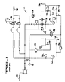
- FIGURE 1 is a schematic flow diagram of a prior art apparatus for applying a heated Type I ADF and water mixture to an aircraft.
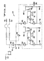
- FIGURE 2 is a schematic flow diagram of an apparatus embodying various features of the invention for applying a heated Type II ADF and water mixture to an aircraft.
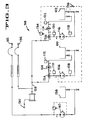
- FIGURE 3 is a schematic flow diagram of another appartus embodying various features of the invention for applying a heated ADF and water mixture to an aircraft.
- FIG. 1 A prior art apparatus 10 for applying Type I (ethelyene glycol based) ADF is shown in FIG. 1.
- the apparatus 10 is preferably installed within a deicing vehicle, such as a truck, that can be driven to the location of the aircraft to be deiced.
- the apparatus includes a ground nozzle 12 that can be used for deicing those areas of the aircraft, such as the undercarriage and the undersides of the wing and tail surfaces, that are accessible from the ground.
- a basket nozzle 14 operable from a basket carried at the end of an extendable boom, is provided for deicing the upper wing, tail and fuselage surfaces that cannot conveniently be reached by the ground nozzle 12.
- a proportioning valve 16 of known construction is provided in conjunction with the boom nozzle 14 for enabling the operator to select the proportion of ADF to water in the deicing solution sprayed from the boom nozzle 14.
- the prior art apparatus 10 further includes a first reservoir or ADF storage tank 22 for containing the ADF in substantially undiluted form.
- the ADF is heated by means of an indirectly fired, fluid-to-fluid heat exchanger (not shown) to a typical temperature of approximately of 185° F and is circulated from the ADF storage tank 22 by means of a centrifugal pump 24.
- the prior art apparatus 10 further includes a second reservoir or water storage tank 26 for containing hot water.
- the water in the water storage tank 26 is heated to approximately 185° F by means of a fuel fired combustion heater 28.
- the hot water is circulated from the water storage tank and through the combustion heater 28 by means of a centrifugal pump 30.
- the first and second centrifugal pumps 24, 30 also function, respectively, to supply the hot ADF and the hot water to the ground and boom nozzles 12, 14.
- First and second flow sensors 32, 34 are provided in conjunction with the first and second centrifugal pumps 24, 30 to provide a warning in the event fluid flow through the pumps is, for some reason, not present.
- a plurality of valves 36 are provided for isolating both the ADF and hot water storage tanks 22, 26.
- drain valves 38 are provided for draining the tanks 22, 26.
- a pressure relief valve 40 provides a bypass around the combustion heater 28 in the event of a blockage.
- Two additional pressure relief valves 42, 44 are provided for recirculating the hot ADF and the hot water, respectively, to their respective storage tanks 22, 26 when neither the ground nozzle 12 nor boom nozzle 14 is open.
- a purge valve 46 is provided for purging water from the system to prevent freezing while the apparatus 10 is not in use.
- a deicing apparatus 48 embodying various features of the invention is illustrated in FIG. 2.
- the apparatus 48 operates to heat Type II (propylene glycol based) aircraft deicing fluid and to mix the heated Type II ADF with hot water to create a heated solution or mixture having a predetermined proportion of ADF to water.
- Type II propylene glycol based
- the apparatus 48 includes a ground nozzle 50 for use from the ground and a pair of additional basket nozzles 52, 54 operable from a basket carried at the end of an extendable boom.
- One of the basket nozzles 52 provides a relatively low flow rate (e.g. 20 gallons per minutes (gpm)) for deicing relatively low surfaces, while the other basket nozzle 54 provides a greater flowrate (e.g. 40-120 gpm) for deicing larger surfaces.
- gpm gallons per minutes
- the deicing apparatus includes a first reservoir or hot ADF storage tank 56 for storing heated, substantially undiluted, Type II ADF.
- the ADF is heated by means of a fuel fired combustion heater 58 such as a two pass combustion heater of known construction.
- the ADF is circulated through the combustion heater 58 by means of a first heater circulation pump 60, which preferably comprises a diaphram type positive displacement pump.
- Undiluted ADF is drawn from the ADF storage tank 56 by the pump 60 and is circulated through the combustion heater 58 back to the tank 56.
- a flow sensor 62 verifies that ADF is being circulated by the pump 60, and a pair of temperature sensors 64, 66 monitor the temperature of the ADF on both sides of the combution heater 58.
- the hot water is contained in a second reservoir or hot water storage tank 68 and is heated by means of a second combustion heater 70 that preferably also comprises a two pass combustion heater of known construction.
- a second heater circulation pump 72 which also preferably comprises a diapham type positive displacement pump, draws water from the hot water storage tank 68 and circulates the water through the combustion heater 70 back to the tank 68.
- An additional flow sensor 74 verifies the circulation of hot water, and a pair of additional temperature sensors 76, 78 sense the water temperature on both sides of the combustion heater 70.
- the water in the tank 68 is maintained at approximately 185° F.
- the apparatus 48 includes proportional mixing means for mixing the heated ADF with the heated water in a desired, predetermined proportion.
- the proportional mixing means includes a first fluid delivery pump 80, which preferably comprises a diaphram type positive displacement pump, having its input connected to the outlet side of the ADF combustion heater 58 and having its output coupled to the nozzles 50, 52, 54.
- the proportional mixing means further incudes a second fluid delivery pump 82, which also preferably comprises a diaphram type positive displacement pump, having its input connected to the outlet side of the water combustion heater 70 and having its output also connected, through a common conduit 84, to the nozzles 80, 82.
- the volumetric outputs of the ADF and hot water fluid delivery pumps 80, 82 are independently controlable so that the ratio of hot ADF delivered by the ADF fluid delivery pump 80 to hot water delivered by the hot water fluid delivery pump 82 can be controlled to achieve a desired proportion of ADF to water in the deicing mixture delivered by the nozzles 50, 52, 54.
- the quantity or flow rate of the combined ADF and water delivered by the nozzles 50, 52, 54 can be controlled by controlling the magnitude of the volumetric outputs of the ADF and water fluid delivery pumps 80, 82 while maintaining the desired ratio between their volumetric outputs.
- the ground nozzle 50 and the low flow rate basket nozzle 52 are enabled by means of a solenoid operated enable valve 86 in the common fluid conduit 84 leading from the combined outputs of the ADF and water fluid delivery pumps 80, 82 to the nozzles 50, 52.
- a pressure relief valve 88 coupled between the combined outputs of the ADF and hot water fluid delivery pumps 80, 82 and the hot water storage tank 68, provides a drain path for the combined ADF and water when the boom is retracted.
- a check valve 90 across the enable valve 86 provides a drainage path in the event the boom is retracted while the enable valve 86 is closed.
- a plurality of additional valves 94 provide for controlled isolation of the various system components. Drain valves 96 are provided for draining the ADF and hot water storage tanks 56, 68.
- FIG. 3 Another Type II ADF deicing apparatus 98 is illustrated in FIG. 3.
- a first reservoir or hot ADF storage tank 100 is provided for storing the substantially undiluted Type II ADF
- a second reservoir or hot water storage tank 102 is provided for storing hot water.
- a fuel fired combustion heater 104 which preferably comprises a two pass combustion heater of known construction, is provided for heating the ADF
- a diaphragm type positive displacement pump 106 is provided for circulating the substantially undiluted ADF from the ADF storage tank 100, through the ADF combustion heater 104, and back to the tank 100.
- a flow sensor 108 verifies the circulation of ADF
- a pair of temperature sensors 110, 112 sense the temperature of the ADF on both sides of the combustion heater 104.
- the water is heated by means of an additional combustion heater 114 which also preferably comprises a two pass combustion heater of known construction.
- Water from the hot water storage tank 102 is circulated through the water combustion heater 114 by means of an additional pump 116 which also preferably comprises a diaphragm type positive displacement pump.
- a flow sensor 118 verifies the circulation of hot water, and a pair of temperature sensors 120, 122 sense the temperature of the water on both sides of the combustion heater 114.
- proportional mixing of the hot ADF and hot water does not require the use of additional pumps but, rather, is provided by the same pumps 106, 116 that circulate the ADF and the water through their respective combustion heaters 104, 114.
- a first three way valve 124 is provided in the fluid conduit leading from the output of the ADF pump 106
- a second three way valve 126 is provided in the fluid conduit leading from the output of the water pump 116.
- the first three way valve 124 is operable to direct the output of the ADF pump 106 to either the ADF combustion heater 104 or to a common conduit 128 leading to a pair of ground and boom nozzles 130, 132.
- the second three way valve 126 is operable to direct hot water to either the water combustion heater 114 or the common conduit 128. Accordingly, when the three way valves 124, 126 are both in one position, the outputs of the ADF and water pumps 106, 116 are combined and delivered to the nozzles 130, 132. When the valves 124, 126 are in the other position, the ADF and the water are circulated through their respective heaters 104, 114 and returned to their respective storage tanks. 100, 102, unmixed.
- Proporational mixing of the ADF and water is achieved by controlling the volumetric outputs of the respective ADF and water pumps 106, 116 so as to achieve a desired ratio of ADF to water. Similarly, the magnitudes of the volumetric outputs are controlled to achieve the desired flow rate at the desired proportion of ADF to water.
- a pressure relief valve 134 is provided for returning the combined ADF and water to the water storage tank 102 when the boom is retracted.
- a purge valve 136 is provided for purging the mixture from the nozzle lines when the apparatus is not in use.
- An additional storage tank 138 for unheated ADF along with an additional diaphragm type positive displacement pump 140 and an aditional basket mounted nozzle 142, provide the availability of cold ADF when it is not neccessary to melt a previous accumulation of snow and ice.
- the apparatus and method of the present invention provides a deicing apparatus that is simpler and more reliable in construction and operation than prior units that employed indirectly fired, fluid-to-fluid heat exchangers. It has been found that the use of directly fired combustion heaters for heating Type II ADF does not result in significant degradation of the Type II ADF and, thus, permits the apparatus and method herein disclosed to exploit the advantages of combustion type heaters.
Abstract
An apparatus and method for applying a heated mixture of propylene glycol based aircraft deicing fluid and water to an aircraft. Propylene glycol based aircraft deicing fluid is heated by means of a directly fired combustion heater (58). The heated aircraft deicing fluid is mixed with hot water to form a deicing mixture for deicing aircraft. Diaphragm type positive displacement pumps (80,82), having controllable volumetric outputs, combine the heated aircraft deicing fluid and the heated water in a desired ratio. The volumetric outputs of the pumps can be varied to achieve a desired proportion of aircraft deicing fluid to water.
Description
- This invention relates generally to aircraft deicing apparatus and methods and, more particularly, to apparatus and methods for applying heated propylene glycol based aircraft deicing fluids to aircraft.
- The accumulation of snow or ice on the wing, tail and other surfaces of an aircraft can drastically degrade the aerodynamic performance of the aircraft. Accordingly, various apparatus and methods have been developed for removing accumulated snow and ice from critical aircraft surfaces as well as for preventing the further accumulation of snow or ice.
- One well known anti-icing technique involves an application of a heated ethylene glycol based or Type I, aircraft deicing fluid ("ADF") to the aircraft. The heated Type I ADF melts the accumulated ice and snow and, because of its solubility in water and its low melting point, helps prevent the melted ice and snow from refreezing. Although effective in removing accumulated ice and snow immediately before take off, heated Type I ADF is largely ineffective in preventing further icing for more than a brief period. Accordingly, it is not well suited for protecting aircraft that will remain on the ground in icing conditions for several minutes or hours following deicing.
- To provide effective protection against the accumulation of ice and snow when an aircraft stands idle for more than brief periods in icing conditions, propylene glycol based, or Type II, aircraft deicing fluids have been developed. These commercially available Type II ADF's typically include various additives that enhance the pseudo-plastic nature of the propylene glycol fluid. The result is a viscous ADF that, when used alone or in solution with water, forms an adherent, protective film on aircraft surfaces that guards against the further accumulation of snow and ice while the aircraft is stationary, but that loses viscosity and shears away from the surfaces under the shearing force of the relative wind during the takeoff roll.
- Like Type I ADF, Type II ADF can be heated to permit the removal of already accumulated ice and snow from an aircraft. However, because of its complex chemical structure and the presence of the various chemical additives, Type II ADF is easily damaged by excessive heat. Care must be taken to avoid damaging the fluid during heating. Heretofore, indirectly heated fluid-to-fluid heat exchangers have been used to ensure that the Type II ADF is heated uniformly without any "hot spots" that can cause localized burning or degradation of the Type II ADF. Although effective, such heat exchangers are complicated, expensive, prone to breakdown and difficult to repair.
- In view of the foregoing, it is a general object of the present invention to provide a new and improved apparatus and method for applying heated Type II ADF to an aircraft.
- It is a further object of the present invention to provide a new and improved apparatus and method for applying heated Type II ADF to an aircraft wherein degradation of the Type II ADF during and after heating is avoided.
- It is a still further object of the present invention to provide a new and improved, heated, Type II ADF deicing apparatus and method that is simple, reliable and economical in construction and operation.
- It is a still further object of the present invention to provide a new and improved, heated, Type II ADF deicing apparatus and method that does not involve the use of indirectly fired, fluid-to-fluid heat exchangers.
- The invention provides an apparatus for applying a propylene glycol based aircraft deicing fluid to an aircraft. The apparatus includes a first reservoir for storing the aircraft deicing fluid and a combustion heater in fluid communication with the first reservoir for heating the aircraft deicing fluid. A second reservoir is provided for containing heated water. A proportional mixing system is provided for mixing the heated aircraft deicing fluid with the the heated water in a desired predetermined proportion.
- The invention also provides a method of preparing a heated, aircraft deicing solution that comprises a mixture of propylene glycol based aircraft deicing fluid and water in predetermined proportions. The method includes the steps of heating a quantity of substantially undiluted, propylene glycol based aircraft deicing fluid in a combustion heater and mixing the heated, substantially undiluted aircraft deicing fluid with heated water sufficient to achieve the predetermined proportions.
- In one embodiment, the heated, undiluted, propylene glycol based aircraft deicing fluid and the heated water are pumped by means of separate diaphragm type positive displacement pumps, and the volumetric outputs of the pumps are maintained in a predetermined ratio relative to each other so as to achieve the desires proportion of aircraft deicing fluid to water in the final mixture.
- In one embodiment, the magnitudes of the volumetric outputs of the diaphram type positive displacement pumps are adjusted to achieve a desired overall flow rate while maintaining the desired proportion of aircraft deicing fluid to water in the final mixture.
- The features of the present invention which are believed to be novel are set forth with particularity in the appended claims. The invention, together with the further objects and advantages thereof, may best be understood by reference to the following description taken in conjunction with the accompanying drawings, wherein like reference numerals identify like elements and wherein:
- FIGURE 1 is a schematic flow diagram of a prior art apparatus for applying a heated Type I ADF and water mixture to an aircraft.
- FIGURE 2 is a schematic flow diagram of an apparatus embodying various features of the invention for applying a heated Type II ADF and water mixture to an aircraft.
- FIGURE 3 is a schematic flow diagram of another appartus embodying various features of the invention for applying a heated ADF and water mixture to an aircraft.
- A
prior art apparatus 10 for applying Type I (ethelyene glycol based) ADF is shown in FIG. 1. Theapparatus 10 is preferably installed within a deicing vehicle, such as a truck, that can be driven to the location of the aircraft to be deiced. As illustrated, the apparatus includes aground nozzle 12 that can be used for deicing those areas of the aircraft, such as the undercarriage and the undersides of the wing and tail surfaces, that are accessible from the ground. In addition, abasket nozzle 14, operable from a basket carried at the end of an extendable boom, is provided for deicing the upper wing, tail and fuselage surfaces that cannot conveniently be reached by theground nozzle 12. Aproportioning valve 16 of known construction is provided in conjunction with theboom nozzle 14 for enabling the operator to select the proportion of ADF to water in the deicing solution sprayed from theboom nozzle 14. Avariable flow restrictor 18, provided in thesupply conduit 20 for supplying undiluted ADF to theground nozzle 12, controls the proportion of ADF to water in the solution delivered by the ground nozzle. - The
prior art apparatus 10 further includes a first reservoir or ADF storage tank 22 for containing the ADF in substantially undiluted form. The ADF is heated by means of an indirectly fired, fluid-to-fluid heat exchanger (not shown) to a typical temperature of approximately of 185° F and is circulated from the ADF storage tank 22 by means of acentrifugal pump 24. - The
prior art apparatus 10 further includes a second reservoir orwater storage tank 26 for containing hot water. The water in thewater storage tank 26 is heated to approximately 185° F by means of a fuel firedcombustion heater 28. The hot water is circulated from the water storage tank and through thecombustion heater 28 by means of acentrifugal pump 30. - The first and second
centrifugal pumps boom nozzles second flow sensors centrifugal pumps valves 36 are provided for isolating both the ADF and hotwater storage tanks 22, 26. In addition,drain valves 38 are provided for draining thetanks 22, 26. Apressure relief valve 40 provides a bypass around thecombustion heater 28 in the event of a blockage. Two additionalpressure relief valves respective storage tanks 22, 26 when neither theground nozzle 12 norboom nozzle 14 is open. Apurge valve 46 is provided for purging water from the system to prevent freezing while theapparatus 10 is not in use. - A
deicing apparatus 48 embodying various features of the invention is illustrated in FIG. 2. Theapparatus 48 operates to heat Type II (propylene glycol based) aircraft deicing fluid and to mix the heated Type II ADF with hot water to create a heated solution or mixture having a predetermined proportion of ADF to water. - As illustrated, the
apparatus 48 includes aground nozzle 50 for use from the ground and a pair ofadditional basket nozzles 52, 54 operable from a basket carried at the end of an extendable boom. One of the basket nozzles 52 provides a relatively low flow rate (e.g. 20 gallons per minutes (gpm)) for deicing relatively low surfaces, while theother basket nozzle 54 provides a greater flowrate (e.g. 40-120 gpm) for deicing larger surfaces. - The deicing apparatus includes a first reservoir or hot ADF storage tank 56 for storing heated, substantially undiluted, Type II ADF. The ADF is heated by means of a fuel fired
combustion heater 58 such as a two pass combustion heater of known construction. The ADF is circulated through thecombustion heater 58 by means of a firstheater circulation pump 60, which preferably comprises a diaphram type positive displacement pump. Undiluted ADF is drawn from the ADF storage tank 56 by thepump 60 and is circulated through thecombustion heater 58 back to the tank 56. Aflow sensor 62 verifies that ADF is being circulated by thepump 60, and a pair oftemperature sensors combution heater 58. - The hot water is contained in a second reservoir or hot
water storage tank 68 and is heated by means of asecond combustion heater 70 that preferably also comprises a two pass combustion heater of known construction. A second heater circulation pump 72, which also preferably comprises a diapham type positive displacement pump, draws water from the hotwater storage tank 68 and circulates the water through thecombustion heater 70 back to thetank 68. Anadditional flow sensor 74 verifies the circulation of hot water, and a pair ofadditional temperature sensors combustion heater 70. Typically, the water in thetank 68 is maintained at approximately 185° F. - To control the ratio of ADF to water in the deicing mixture discharged by the
nozzles apparatus 48 includes proportional mixing means for mixing the heated ADF with the heated water in a desired, predetermined proportion. In the illustrated embodiment, the proportional mixing means includes a firstfluid delivery pump 80, which preferably comprises a diaphram type positive displacement pump, having its input connected to the outlet side of theADF combustion heater 58 and having its output coupled to thenozzles fluid delivery pump 82, which also preferably comprises a diaphram type positive displacement pump, having its input connected to the outlet side of thewater combustion heater 70 and having its output also connected, through acommon conduit 84, to thenozzles fluid delivery pump 80 to hot water delivered by the hot waterfluid delivery pump 82 can be controlled to achieve a desired proportion of ADF to water in the deicing mixture delivered by thenozzles nozzles - The
ground nozzle 50 and the low flow rate basket nozzle 52 are enabled by means of a solenoid operated enablevalve 86 in thecommon fluid conduit 84 leading from the combined outputs of the ADF and water fluid delivery pumps 80, 82 to thenozzles 50, 52. Apressure relief valve 88, coupled between the combined outputs of the ADF and hot water fluid delivery pumps 80, 82 and the hotwater storage tank 68, provides a drain path for the combined ADF and water when the boom is retracted. Acheck valve 90 across the enablevalve 86 provides a drainage path in the event the boom is retracted while the enablevalve 86 is closed. A solenoid operated purge valve 92 coupled between the output of the ADFfluid delivery pump 80 and thehot water storage 68 tank allows the operator to purge the fluid conduits leading to thevarious nozzles 50, 52, 55. A plurality ofadditional valves 94 provide for controlled isolation of the various system components. Drain valves 96 are provided for draining the ADF and hotwater storage tanks 56, 68. - Another Type II
ADF deicing apparatus 98 is illustrated in FIG. 3. In this apparatus, a first reservoir or hotADF storage tank 100 is provided for storing the substantially undiluted Type II ADF, and a second reservoir or hotwater storage tank 102 is provided for storing hot water. In accordance with one aspect of the invention, a fuel firedcombustion heater 104, which preferably comprises a two pass combustion heater of known construction, is provided for heating the ADF, and a diaphragm typepositive displacement pump 106 is provided for circulating the substantially undiluted ADF from theADF storage tank 100, through theADF combustion heater 104, and back to thetank 100. Aflow sensor 108 verifies the circulation of ADF, and a pair oftemperature sensors combustion heater 104. - The water is heated by means of an
additional combustion heater 114 which also preferably comprises a two pass combustion heater of known construction. Water from the hotwater storage tank 102 is circulated through thewater combustion heater 114 by means of anadditional pump 116 which also preferably comprises a diaphragm type positive displacement pump. Aflow sensor 118 verifies the circulation of hot water, and a pair oftemperature sensors combustion heater 114. - In contrast to the apparatus shown in FIG. 2, proportional mixing of the hot ADF and hot water does not require the use of additional pumps but, rather, is provided by the
same pumps respective combustion heaters way valve 124 is provided in the fluid conduit leading from the output of theADF pump 106, and a second threeway valve 126 is provided in the fluid conduit leading from the output of thewater pump 116. The first threeway valve 124 is operable to direct the output of theADF pump 106 to either theADF combustion heater 104 or to acommon conduit 128 leading to a pair of ground andboom nozzles way valve 126 is operable to direct hot water to either thewater combustion heater 114 or thecommon conduit 128. Accordingly, when the threeway valves nozzles valves respective heaters - Proporational mixing of the ADF and water is achieved by controlling the volumetric outputs of the respective ADF and water pumps 106, 116 so as to achieve a desired ratio of ADF to water. Similarly, the magnitudes of the volumetric outputs are controlled to achieve the desired flow rate at the desired proportion of ADF to water.
- A
pressure relief valve 134 is provided for returning the combined ADF and water to thewater storage tank 102 when the boom is retracted. Apurge valve 136 is provided for purging the mixture from the nozzle lines when the apparatus is not in use. - An
additional storage tank 138 for unheated ADF, along with an additional diaphragm type positive displacement pump 140 and an aditional basket mountednozzle 142, provide the availability of cold ADF when it is not neccessary to melt a previous accumulation of snow and ice. - The apparatus and method of the present invention, and in particular, the use of directly fired combustion heaters, provides a deicing apparatus that is simpler and more reliable in construction and operation than prior units that employed indirectly fired, fluid-to-fluid heat exchangers. It has been found that the use of directly fired combustion heaters for heating Type II ADF does not result in significant degradation of the Type II ADF and, thus, permits the apparatus and method herein disclosed to exploit the advantages of combustion type heaters.
- Although specific configurations of the aircraft deicing apparatus have been disclosed, it will be appreciated that other configurations can be employed. Similarly, while specific positive displacement pumps and specific combustion heater configurations have been described, other positive displacement pumps and combustion heaters may by substituted. Similarly, the specific flow rates and temperatures herein described are meant to be illustrative rather than limiting.
- While a particular embodiment of the invention has been shown and described, it will be obvious of those skilled in the art that changes and modifications may be made without departing from the invention in its broader aspects, and, therefore, the aim in the appended claims is to cover all such changes and modifications as fall within the true spirit and scope of the invention.
Claims (17)
- An apparatus for applying a propylene glycol based aircraft deicing fluid to an aircraft comprising:
a first reservoir for storing the aircraft deicing fluid;
a combustion heater in fluid communication with said first reservoir for heating the aircraft deicing fluid;
a second reservoir for containing heated water; and
proportional mixing means for mixing the heated aircraft deicing fluid with the heated water in a desired predetermined proportion. - An apparatus as defined in claim 1 wherein said proportional mixing means includes a first fluid delivery pump for providing the heated aircraft deicing fluid at a first desired flow rate, a second fluid delivery pump for pumping the heated water at a second desired flow rate, and means for mixing the heated aircraft deicing fluid pumped by said first pump with the heated water pumped by said second pump.
- An apparatus as defined in claim 2 wherein said apparatus further comprises a first heater circulation pump for circulating the aircraft deicing fluid from the first reservoir through the combustion heater and back to the first reservoir.
- An apparatus as defined in claim 3 wherein said apparatus further comprises an additional combustion heater and a second heater circulation pump for circulating the heated water from the second reservoir through the additional combustion heater and back to the second reservoir.
- An apparatus as defined in claim 4 wherein each of said first and second fluid delivery pumps and said first heater circulation pump comprises a diaphragm type positive displacement pump.
- An apparatus as defined in claim 2 wherein said proportional mixing means includes a user actuable control for controllably varying the volumetric output of said first and second fluid delivery pumps to vary the proportion of aircraft deicing fluid to water in the mixture provided by said proportional mixing means.
- An apparatus as defined in claim 6 wherein said user actuable control also varies the volumetric outputs of said first and second fluid delivery pumps to achieve a desired overall flow rate at a desires predetermined proportion of aircraft deicing fluid to water.
- An apparatus as defined in claim 7 wherein said user actuable control includes a mixture control operable to establish a desired ratio in the volumetric outputs of the first and second fluid delivery pumps, and further includes a flow control operable to establish a desired magnitude in the combined volumetric outputs of said first and second fluid delivery pumps so that said mixture control controls the proportion of aircraft deicing fluid to water in the mixture provided by said apparatus and said flow control controls the flow rate of the mixture provided by said apparatus.
- A method of preparing a heated aircraft deicing solution comprising a mixture of propylene glycol based aircraft deicing fluid and water in predetermined proportions, said method comprising the steps of:
heating a quantity of substantially undiluted propylene glycol based aircraft deicing fluid in a combustion heater; and
mixing the heated substantially undiluted aircraft deicing fluid with heated water in a ratio sufficient to achieve the predetermined proportions. - A method as defined in claim 9 further comprising the step of circulating the substantially undiluted aircraft deicing fluid from a first reservoir through a combustion heater and back to the reservoir so as to raise the temperature of substantially the entire quantity of undiluted aircraft deicing fluid within the reservoir prior to mixing with the heated water.
- A method as defined in claim 10 further comprising the step of generating the heated water by circulating water from a second reservoir through an additional combustion heater and back to the additional reservoir so as to raise the temperature of the water in the second reservoir prior to mixing the heated substantially undiluted aircraft deicing fluid.
- A method as defined in claim 9 further comprising the steps of conveying the heated substantially undiluted aircraft deicing fluid by means of a first diaphragm type positive displacement pump and conveying the heated water by means of a second diaphragm type positive displacement pump.
- A method as defined in claim 12 further comprising the step of setting the volumetric output of the first diaphragm type positive displacement pump at a predetermined ratio relative to the volumetric output of the second diaphragm type positive displacement pump to thereby achieve the desired predetermined proportion of aircraft deicing fluid to water.
- A method as defined in claim 13 further comprising the step of setting the magnitudes of the volumetric outputs of the first and second diaphragm type positive displacement pumps to achieve a desired overall flow rate of the mixed aircraft deicing fluid and water while maintaining the predetermined proportion of aircraft deicing fluid to water.
- An apparatus for applying a mixture of a propylene glycol based aircraft deicing fluid and water to an aircraft comprising:
a first storage tank for holding the propylene glycol based aircraft deicing fluid in substantially undiluted form;
a two pass combustion heater;
a first diaphragm type positive displacement pump operable to pump the aircraft deicing fluid from said first storage tank and through said two pass combustion heater;
a second storage tank for holding the water;
a water heater;
a second diaphragm type positive displacement pump operable to pump the water from said second storage tank and through said water heater; and
proportional mixing means for mixing the heated aircraft deicing fluid and the heated water in a desired ratio to achieve a predetermined desired proportion of aircraft deicing fluid to water in the mixture to be applied to the aircraft. - An apparatus as defined in claim 15 wherein said proporational mixing means includes a first fluid delivery pump, separate from said first diaphragm type positive displacement pump, for pumping the heated aircraft deicing fluid at a controllable flow rate, and a second fluid delivery pump, separate from said second diaphragm type positive displacement pump, for pumping the heated water at a controllable flow rate.
- An apparartus as defined in claim 15 wherein said proportional mixing means includes a common conduit for mixing aircraft deicing fluid and water, a first three way valve in fluid communication with the output of said first diaphragm type positive displacement pump for controllably diverting the output of said first diaphragm type positive displacement pump to said common conduit, and a second three way valve in fluid communication with the output of said second diaphragm type positive displacement pump for controllably diverting the output of said second diaphragm type positive displacement pump to said common conduit.
Applications Claiming Priority (2)
| Application Number | Priority Date | Filing Date | Title |
|---|---|---|---|
| US07/474,386 US5096145A (en) | 1990-02-05 | 1990-02-05 | Aircraft deicing apparatus and method |
| US474386 | 1990-02-05 |
Publications (1)
| Publication Number | Publication Date |
|---|---|
| EP0441202A1 true EP0441202A1 (en) | 1991-08-14 |
Family
ID=23883294
Family Applications (1)
| Application Number | Title | Priority Date | Filing Date |
|---|---|---|---|
| EP91100968A Withdrawn EP0441202A1 (en) | 1990-02-05 | 1991-01-25 | Aircraft deicing apparatus and method |
Country Status (6)
| Country | Link |
|---|---|
| US (1) | US5096145A (en) |
| EP (1) | EP0441202A1 (en) |
| JP (1) | JPH04212699A (en) |
| CA (1) | CA2035115A1 (en) |
| FI (1) | FI910487A (en) |
| NO (1) | NO171263C (en) |
Cited By (4)
| Publication number | Priority date | Publication date | Assignee | Title |
|---|---|---|---|---|
| EP0606909A1 (en) * | 1993-01-15 | 1994-07-20 | Fmc Corporation | Aircraft deicer pumping system |
| AT1332U1 (en) * | 1996-06-13 | 1997-03-25 | Zellinger Gmbh | WASHING MACHINE, ESPECIALLY FOR AIRCRAFT NOZZLE UNITS |
| EP3461743B1 (en) * | 2017-09-29 | 2020-03-25 | The Boeing Company | Combined fluid ice protection and electronics cooling system |
| RU197493U1 (en) * | 2019-07-09 | 2020-04-30 | Юрий Степанович Бойко | Electric Airship Anti-icing Liquid System |
Families Citing this family (19)
| Publication number | Priority date | Publication date | Assignee | Title |
|---|---|---|---|---|
| US5244168A (en) * | 1991-12-13 | 1993-09-14 | Williams Lee A | Methodology and apparatus for forced air aircraft deicing |
| WO1995001278A1 (en) * | 1991-12-13 | 1995-01-12 | Williams Lee A | Methodology and apparatus for forced air aircraft deicing |
| US6258758B1 (en) | 1996-04-26 | 2001-07-10 | Platinum Research Organization Llc | Catalyzed surface composition altering and surface coating formulations and methods |
| US6047926A (en) | 1996-06-28 | 2000-04-11 | Alliedsignal Inc. | Hybrid deicing system and method of operation |
| US6360992B1 (en) | 1996-06-28 | 2002-03-26 | Honeywell International Inc. | Hybrid deicing system and method of operation |
| US6547187B2 (en) | 1998-08-05 | 2003-04-15 | Fmc Technologies, Inc. | Apparatus and method for deicing aircraft using compact, lightweight air source |
| US6045092A (en) * | 1998-08-05 | 2000-04-04 | Fmc Corporation | Apparatus and method for deicing aircraft |
| US6766836B2 (en) | 2001-07-24 | 2004-07-27 | Edwards Electrical & Mechanical, Inc. | Glycol proportioning panel |
| CA2356066A1 (en) | 2001-08-28 | 2003-02-28 | John M. Goston | Arrangements for the de-icing and anti-icing of aircraft |
| US6623657B1 (en) | 2002-04-18 | 2003-09-23 | Board Of Trustees Of Michigan State University | Water-activated, exothermic chemical deicing formulations |
| PL211575B1 (en) * | 2002-08-26 | 2012-05-31 | Dalsgaard Nielsen Aps | A method of determining the risk of ice deposition due to precipitation and apparatus for exercising the method |
| US7934680B2 (en) * | 2007-05-21 | 2011-05-03 | Global Ground Support, Llc | Apparatus and method for blending fluids |
| US8252149B2 (en) | 2007-07-24 | 2012-08-28 | Brad Michael Malatesta | Method of cleaning and recycling glycol-tainted water from de-icing operations at airports |
| WO2011163592A2 (en) | 2010-06-24 | 2011-12-29 | Board Of Regents, The University Of Texas System | Alkylphoshorofluoridothioates having low wear volume and methods for synthesizing and using same |
| US20130240665A1 (en) * | 2012-03-16 | 2013-09-19 | Borealis Technical Limited | Method for improving efficiency of airport deicing operations |
| AU2013200596B2 (en) * | 2012-03-22 | 2013-11-28 | Rheem Australia Pty Limited | A Circulating Hot Water System and or Appliance |
| WO2013169779A1 (en) | 2012-05-07 | 2013-11-14 | Board Of Regents, The University Of Texas System | Synergistic mixtures of ionic liquids with other ionic liquids and/or with ashless thiophosphates for antiwear and/or friction reduction applications |
| US10837676B2 (en) | 2018-04-23 | 2020-11-17 | Rheem Manufacturing Company | Electric water heater having a bypass |
| CN110816853A (en) * | 2019-10-12 | 2020-02-21 | 中航通飞研究院有限公司 | Electric airplane deicing and preventing device and method |
Citations (3)
| Publication number | Priority date | Publication date | Assignee | Title |
|---|---|---|---|---|
| EP0030454A2 (en) * | 1979-12-04 | 1981-06-17 | Fmc Corporation | Method and apparatus for applying a de-icing fluid |
| WO1986000592A1 (en) * | 1984-07-06 | 1986-01-30 | Instrumentointi Oy | A method for selecting and controlling the mixture ratio of water and glycol for deicing and anti-icing and an equipment for carrying it out |
| US4826107A (en) * | 1987-04-13 | 1989-05-02 | Thornton Trump Walter E | Aircraft deicing unit having rapid heating capability |
Family Cites Families (3)
| Publication number | Priority date | Publication date | Assignee | Title |
|---|---|---|---|---|
| US4191348A (en) * | 1977-11-10 | 1980-03-04 | Holwerda-Huizenga Co. | Deicing system |
| US4197712A (en) * | 1978-04-21 | 1980-04-15 | Brigham William D | Fluid pumping and heating system |
| US4842005A (en) * | 1988-01-26 | 1989-06-27 | Itt Corporation | Mixing apparatus and system |
-
1990
- 1990-02-05 US US07/474,386 patent/US5096145A/en not_active Expired - Fee Related
-
1991
- 1991-01-25 EP EP91100968A patent/EP0441202A1/en not_active Withdrawn
- 1991-01-28 CA CA002035115A patent/CA2035115A1/en not_active Abandoned
- 1991-01-31 NO NO910370A patent/NO171263C/en unknown
- 1991-02-01 FI FI910487A patent/FI910487A/en not_active Application Discontinuation
- 1991-02-04 JP JP3035611A patent/JPH04212699A/en active Pending
Patent Citations (3)
| Publication number | Priority date | Publication date | Assignee | Title |
|---|---|---|---|---|
| EP0030454A2 (en) * | 1979-12-04 | 1981-06-17 | Fmc Corporation | Method and apparatus for applying a de-icing fluid |
| WO1986000592A1 (en) * | 1984-07-06 | 1986-01-30 | Instrumentointi Oy | A method for selecting and controlling the mixture ratio of water and glycol for deicing and anti-icing and an equipment for carrying it out |
| US4826107A (en) * | 1987-04-13 | 1989-05-02 | Thornton Trump Walter E | Aircraft deicing unit having rapid heating capability |
Cited By (4)
| Publication number | Priority date | Publication date | Assignee | Title |
|---|---|---|---|---|
| EP0606909A1 (en) * | 1993-01-15 | 1994-07-20 | Fmc Corporation | Aircraft deicer pumping system |
| AT1332U1 (en) * | 1996-06-13 | 1997-03-25 | Zellinger Gmbh | WASHING MACHINE, ESPECIALLY FOR AIRCRAFT NOZZLE UNITS |
| EP3461743B1 (en) * | 2017-09-29 | 2020-03-25 | The Boeing Company | Combined fluid ice protection and electronics cooling system |
| RU197493U1 (en) * | 2019-07-09 | 2020-04-30 | Юрий Степанович Бойко | Electric Airship Anti-icing Liquid System |
Also Published As
| Publication number | Publication date |
|---|---|
| NO171263B (en) | 1992-11-09 |
| NO171263C (en) | 1993-02-17 |
| JPH04212699A (en) | 1992-08-04 |
| CA2035115A1 (en) | 1991-08-06 |
| NO910370D0 (en) | 1991-01-31 |
| NO910370L (en) | 1991-08-06 |
| FI910487A (en) | 1991-08-06 |
| FI910487A0 (en) | 1991-02-01 |
| US5096145A (en) | 1992-03-17 |
Similar Documents
| Publication | Publication Date | Title |
|---|---|---|
| US5096145A (en) | Aircraft deicing apparatus and method | |
| US5098036A (en) | Flameless deicer | |
| US5028017A (en) | Mobile system for deicing aircraft | |
| US5242133A (en) | Method and apparatus for heating and delivering deicing fluids | |
| US4191348A (en) | Deicing system | |
| US7934680B2 (en) | Apparatus and method for blending fluids | |
| CA1158135A (en) | Proportional mix system and method for applying a thixotropic de-icing fluid to an aircraft | |
| US6360730B1 (en) | Inert loading jet fuel | |
| US5244168A (en) | Methodology and apparatus for forced air aircraft deicing | |
| US5845848A (en) | Deicer | |
| EP0134690A2 (en) | Ambient air heated electrically assisted cryogen vaporiser | |
| CA2208959C (en) | Method and apparatus for using hot fuels to de-ice aircraft | |
| US5222696A (en) | Flameless deicer | |
| US4073437A (en) | Conversion package for aircraft de-icing machines | |
| JP2019081537A (en) | Combined fluid ice protection and electronic cooling system | |
| WO1996020110A9 (en) | Method and apparatus for using hot fuels to de-ice aircraft | |
| US6093247A (en) | Distribution system for applying a viscous material to a roof | |
| CA2356066A1 (en) | Arrangements for the de-icing and anti-icing of aircraft | |
| FI88487B (en) | VAERMEVAEXLARE FOER EN MOBIL AVISNINGSANORDNING FOER FLYGPLAN OCH FOERFARANDE FOER DESS ANVAENDNING | |
| US4085543A (en) | Heat distribution system | |
| CA2564016C (en) | Spray-regulating system incorporated in aircraft anti-icers | |
| CN213057572U (en) | Liquid path system of deicing vehicle and deicing vehicle | |
| US20240130352A1 (en) | Apparatus and method for controlling weed growing on a ground surface | |
| JPH0229040Y2 (en) | ||
| JP2003267298A (en) | Snow removing device for aircraft |
Legal Events
| Date | Code | Title | Description |
|---|---|---|---|
| PUAI | Public reference made under article 153(3) epc to a published international application that has entered the european phase |
Free format text: ORIGINAL CODE: 0009012 |
|
| AK | Designated contracting states |
Kind code of ref document: A1 Designated state(s): AT BE CH DE DK ES FR GB GR IT LI NL SE |
|
| 17P | Request for examination filed |
Effective date: 19910823 |
|
| 17Q | First examination report despatched |
Effective date: 19921029 |
|
| STAA | Information on the status of an ep patent application or granted ep patent |
Free format text: STATUS: THE APPLICATION IS DEEMED TO BE WITHDRAWN |
|
| 18D | Application deemed to be withdrawn |
Effective date: 19950731 |