EP3461685B1 - Verfahren zum betrieb einer elektromotorischen massageeinrichtung eines sitzes - Google Patents
Verfahren zum betrieb einer elektromotorischen massageeinrichtung eines sitzes Download PDFInfo
- Publication number
- EP3461685B1 EP3461685B1 EP18186951.2A EP18186951A EP3461685B1 EP 3461685 B1 EP3461685 B1 EP 3461685B1 EP 18186951 A EP18186951 A EP 18186951A EP 3461685 B1 EP3461685 B1 EP 3461685B1
- Authority
- EP
- European Patent Office
- Prior art keywords
- seat
- reference value
- electric motor
- massage
- determined
- Prior art date
- Legal status (The legal status is an assumption and is not a legal conclusion. Google has not performed a legal analysis and makes no representation as to the accuracy of the status listed.)
- Active
Links
Images


Classifications
-
- B—PERFORMING OPERATIONS; TRANSPORTING
- B60—VEHICLES IN GENERAL
- B60N—SEATS SPECIALLY ADAPTED FOR VEHICLES; VEHICLE PASSENGER ACCOMMODATION NOT OTHERWISE PROVIDED FOR
- B60N2/00—Seats specially adapted for vehicles; Arrangement or mounting of seats in vehicles
- B60N2/90—Details or parts not otherwise provided for
- B60N2/976—Details or parts not otherwise provided for massaging systems
-
- A—HUMAN NECESSITIES
- A61—MEDICAL OR VETERINARY SCIENCE; HYGIENE
- A61H—PHYSICAL THERAPY APPARATUS, e.g. DEVICES FOR LOCATING OR STIMULATING REFLEX POINTS IN THE BODY; ARTIFICIAL RESPIRATION; MASSAGE; BATHING DEVICES FOR SPECIAL THERAPEUTIC OR HYGIENIC PURPOSES OR SPECIFIC PARTS OF THE BODY
- A61H23/00—Percussion or vibration massage, e.g. using supersonic vibration; Suction-vibration massage; Massage with moving diaphragms
- A61H23/02—Percussion or vibration massage, e.g. using supersonic vibration; Suction-vibration massage; Massage with moving diaphragms with electric or magnetic drive
-
- A—HUMAN NECESSITIES
- A61—MEDICAL OR VETERINARY SCIENCE; HYGIENE
- A61H—PHYSICAL THERAPY APPARATUS, e.g. DEVICES FOR LOCATING OR STIMULATING REFLEX POINTS IN THE BODY; ARTIFICIAL RESPIRATION; MASSAGE; BATHING DEVICES FOR SPECIAL THERAPEUTIC OR HYGIENIC PURPOSES OR SPECIFIC PARTS OF THE BODY
- A61H23/00—Percussion or vibration massage, e.g. using supersonic vibration; Suction-vibration massage; Massage with moving diaphragms
- A61H23/02—Percussion or vibration massage, e.g. using supersonic vibration; Suction-vibration massage; Massage with moving diaphragms with electric or magnetic drive
- A61H23/0254—Percussion or vibration massage, e.g. using supersonic vibration; Suction-vibration massage; Massage with moving diaphragms with electric or magnetic drive with rotary motor
- A61H23/0263—Percussion or vibration massage, e.g. using supersonic vibration; Suction-vibration massage; Massage with moving diaphragms with electric or magnetic drive with rotary motor using rotating unbalanced masses
-
- B—PERFORMING OPERATIONS; TRANSPORTING
- B60—VEHICLES IN GENERAL
- B60N—SEATS SPECIALLY ADAPTED FOR VEHICLES; VEHICLE PASSENGER ACCOMMODATION NOT OTHERWISE PROVIDED FOR
- B60N2/00—Seats specially adapted for vehicles; Arrangement or mounting of seats in vehicles
- B60N2/002—Seats provided with an occupancy detection means mounted therein or thereon
- B60N2/0021—Seats provided with an occupancy detection means mounted therein or thereon characterised by the type of sensor or measurement
- B60N2/0024—Seats provided with an occupancy detection means mounted therein or thereon characterised by the type of sensor or measurement for identifying, categorising or investigation of the occupant or object on the seat
- B60N2/0027—Seats provided with an occupancy detection means mounted therein or thereon characterised by the type of sensor or measurement for identifying, categorising or investigation of the occupant or object on the seat for detecting the position of the occupant or of occupant's body part
-
- B—PERFORMING OPERATIONS; TRANSPORTING
- B60—VEHICLES IN GENERAL
- B60N—SEATS SPECIALLY ADAPTED FOR VEHICLES; VEHICLE PASSENGER ACCOMMODATION NOT OTHERWISE PROVIDED FOR
- B60N2/00—Seats specially adapted for vehicles; Arrangement or mounting of seats in vehicles
- B60N2/02—Seats specially adapted for vehicles; Arrangement or mounting of seats in vehicles the seat or part thereof being movable, e.g. adjustable
- B60N2/0224—Non-manual adjustments, e.g. with electrical operation
- B60N2/02246—Electric motors therefor
-
- A—HUMAN NECESSITIES
- A61—MEDICAL OR VETERINARY SCIENCE; HYGIENE
- A61H—PHYSICAL THERAPY APPARATUS, e.g. DEVICES FOR LOCATING OR STIMULATING REFLEX POINTS IN THE BODY; ARTIFICIAL RESPIRATION; MASSAGE; BATHING DEVICES FOR SPECIAL THERAPEUTIC OR HYGIENIC PURPOSES OR SPECIFIC PARTS OF THE BODY
- A61H2201/00—Characteristics of apparatus not provided for in the preceding codes
- A61H2201/01—Constructive details
- A61H2201/0119—Support for the device
- A61H2201/0138—Support for the device incorporated in furniture
- A61H2201/0149—Seat or chair
-
- A—HUMAN NECESSITIES
- A61—MEDICAL OR VETERINARY SCIENCE; HYGIENE
- A61H—PHYSICAL THERAPY APPARATUS, e.g. DEVICES FOR LOCATING OR STIMULATING REFLEX POINTS IN THE BODY; ARTIFICIAL RESPIRATION; MASSAGE; BATHING DEVICES FOR SPECIAL THERAPEUTIC OR HYGIENIC PURPOSES OR SPECIFIC PARTS OF THE BODY
- A61H2201/00—Characteristics of apparatus not provided for in the preceding codes
- A61H2201/12—Driving means
- A61H2201/1207—Driving means with electric or magnetic drive
- A61H2201/1215—Rotary drive
-
- A—HUMAN NECESSITIES
- A61—MEDICAL OR VETERINARY SCIENCE; HYGIENE
- A61H—PHYSICAL THERAPY APPARATUS, e.g. DEVICES FOR LOCATING OR STIMULATING REFLEX POINTS IN THE BODY; ARTIFICIAL RESPIRATION; MASSAGE; BATHING DEVICES FOR SPECIAL THERAPEUTIC OR HYGIENIC PURPOSES OR SPECIFIC PARTS OF THE BODY
- A61H2201/00—Characteristics of apparatus not provided for in the preceding codes
- A61H2201/50—Control means thereof
- A61H2201/5058—Sensors or detectors
- A61H2201/5061—Force sensors
-
- A—HUMAN NECESSITIES
- A61—MEDICAL OR VETERINARY SCIENCE; HYGIENE
- A61H—PHYSICAL THERAPY APPARATUS, e.g. DEVICES FOR LOCATING OR STIMULATING REFLEX POINTS IN THE BODY; ARTIFICIAL RESPIRATION; MASSAGE; BATHING DEVICES FOR SPECIAL THERAPEUTIC OR HYGIENIC PURPOSES OR SPECIFIC PARTS OF THE BODY
- A61H2201/00—Characteristics of apparatus not provided for in the preceding codes
- A61H2201/50—Control means thereof
- A61H2201/5058—Sensors or detectors
- A61H2201/5064—Position sensors
-
- A—HUMAN NECESSITIES
- A61—MEDICAL OR VETERINARY SCIENCE; HYGIENE
- A61H—PHYSICAL THERAPY APPARATUS, e.g. DEVICES FOR LOCATING OR STIMULATING REFLEX POINTS IN THE BODY; ARTIFICIAL RESPIRATION; MASSAGE; BATHING DEVICES FOR SPECIAL THERAPEUTIC OR HYGIENIC PURPOSES OR SPECIFIC PARTS OF THE BODY
- A61H2203/00—Additional characteristics concerning the patient
- A61H2203/04—Position of the patient
- A61H2203/0425—Sitting on the buttocks
- A61H2203/0431—Sitting on the buttocks in 90°/90°-position, like on a chair
-
- G—PHYSICS
- G01—MEASURING; TESTING
- G01G—WEIGHING
- G01G19/00—Weighing apparatus or methods adapted for special purposes not provided for in the preceding groups
- G01G19/40—Weighing apparatus or methods adapted for special purposes not provided for in the preceding groups with provisions for indicating, recording, or computing price or other quantities dependent on the weight
- G01G19/413—Weighing apparatus or methods adapted for special purposes not provided for in the preceding groups with provisions for indicating, recording, or computing price or other quantities dependent on the weight using electromechanical or electronic computing means
- G01G19/414—Weighing apparatus or methods adapted for special purposes not provided for in the preceding groups with provisions for indicating, recording, or computing price or other quantities dependent on the weight using electromechanical or electronic computing means using electronic computing means only
- G01G19/4142—Weighing apparatus or methods adapted for special purposes not provided for in the preceding groups with provisions for indicating, recording, or computing price or other quantities dependent on the weight using electromechanical or electronic computing means using electronic computing means only for controlling activation of safety devices, e.g. airbag systems
-
- G—PHYSICS
- G01—MEASURING; TESTING
- G01G—WEIGHING
- G01G19/00—Weighing apparatus or methods adapted for special purposes not provided for in the preceding groups
- G01G19/52—Weighing apparatus combined with other objects, e.g. furniture
Definitions
- the invention relates both to a method for operating an electromotive massage device of a seat, which comprises a massage drive with an electric motor, and to an electromotive massage device of a seat.
- the seat is preferably a component of a motor vehicle.
- the invention further relates to a seat of a motor vehicle.
- Motor vehicles include a number of auxiliary units that are not used directly to propel the motor vehicle. Usually, the convenience of the user of the motor vehicle is increased by means of these auxiliary units.
- Such an auxiliary unit is an electromotive massage device which is a component of a vehicle seat. When activated, a specific area of the vehicle seat is periodically adjusted, such as a backrest or part of a backrest. As a result, blood flow to a user of the vehicle seat is stimulated, which is why using the motor vehicle is more pleasant. In this way, journeys with a comparatively long duration can also be carried out by means of the motor vehicle without the user being tired.
- Motor vehicle seats also typically have seat occupancy detection. Depending on the seat occupancy detection, for example, the correct wearing of a belt is monitored and, if necessary, a warning tone is output.
- the airbags are usually only activated in the event of a crash if the seat is occupied.
- a weight sensor is usually used to detect whether the seat is occupied, or a deformation of the seat due to the occupancy by a person detected.
- a capacitive sensor electrode is used, by means of which an electromagnetic field is created and monitored in the area of the seat. In operation, a change in a dielectric constant due to a change in the capacitance is recorded. The change in dielectric constant is due to the presence of a person in the area of the seat. If a change in capacity is thus detected, occupancy of the seat is also recognized. From the DE102015204492 A method is known to equip a seat with massage elements and to use these as sensors for seat occupancy detection.
- the invention is based on the object of specifying a particularly suitable method for operating an electromotive massage device of a seat and a particularly suitable electromotive massage device of a seat and also a particularly suitable seat of a motor vehicle, in particular reducing manufacturing costs and preferably increasing service life and / or comfort and suitably an acoustic impression is improved.
- the method is used to operate an electromotive massage device.
- the electromotive massage device is a component of a seat, and a massage function is carried out as intended by means of the electromotive massage device.
- a component of the seat such as the seat surface or a backrest, is moved, in particular periodically.
- the seat and thus the electromotive massage device are preferably part of a motor vehicle, and the seat is, for example, a driver's seat or a passenger seat.
- the electromotive massage device has a massage drive with an electric motor.
- Another component is in particular by means of the electric motor of the massage drive, by means of which a massage function is carried out.
- a component of the seat is bulged, in particular periodically, by means of the further component, for example a vibration element, an imbalance or a stamp.
- the further component is suitable for this, expediently provided and set up.
- the electric motor is, for example, a brushed commutator motor.
- the electric motor is particularly preferably designed to be brushless and in particular a brushless DC motor (BLDC).
- the electric motor is an asynchronous motor, but preferably a synchronous motor.
- the electric motor is in particular three-phase, the individual phases being connected to one another, for example in a delta or star connection.
- the method provides that the electric motor is energized in one work step.
- a certain electrical voltage is applied to the electric motor.
- the electrical voltage is specified.
- an electrical current flow to the electric motor is set, for example.
- the electrical voltage / electrical current is provided by means of a converter which has, for example, a bridge circuit, such as a B6 circuit.
- the torque of the electric motor is recorded in a further step.
- the torque of the electric motor is determined, which results from the current supply.
- a first reference value is determined on the basis of the torque.
- the first reference value has, for example, only two values as a possible set of values. In particular, one value is used for the first reference value if the torque is above a certain threshold and the other value is otherwise.
- the value range of the first reference value is enlarged and / or in particular discrete.
- the value range of the first reference value is continuous. At least there is a functional relationship between the first reference value and the torque, for example a one-to-one assignment. For example, the detected torque is used as the first reference value.
- an occupancy of at least a section of the seat is determined on the basis of the first reference value.
- the section corresponds completely or at least in part to the component of the seat which is moved when the electric motor is energized.
- the assignment of the section is inferred from the first reference value.
- the occupancy is particularly a burden on the section due to the presence of a person. In other words, it is determined whether the person is sitting on the section or is leaning against it, that is to say whether the person, in particular a driver of the motor vehicle, is in mechanical contact with the section.
- the occupancy of the section of the seat is thus determined on the basis of the torque of the electric motor or on the basis of the first reference value derived therefrom.
- the section is likely to be occupied. If the section is not occupied, only a comparatively low torque is required. Consequently, it is therefore possible to determine the occupancy of the section by means of the torque and therefore also by means of the first reference value. As a result, no further sensors or the like are required, which is why manufacturing costs are reduced.
- the assignment is determined in binary form, that is to say whether an assignment is present or not.
- the occupancy is determined qualitatively, in particular how much pressure / weight the section is loaded with.
- the electromotive massage device expediently has a plurality of such massage drives, which are assigned to different sections of the seat. This makes it possible to determine the position of the user on the seat by means of the massage drives.
- a seating position of the user on the seat is determined based on the occupancy.
- an electromotive adjustment of the seat e.g. an electromotive adjustment of the backrest of the seat, i.e. its angle of inclination with respect to the seat surface, or a transverse movement of the seat.
- the determined is Sitting position made a further adjustment of the motor vehicle, provided the electromotive massage device is part of the motor vehicle.
- a setting of a possible air conditioning system, an audio system or a belt / belt drive is influenced. As a result, comfort is further increased.
- the torque of the electric motor is determined, for example, on the basis of the current consumption.
- the first reference value is determined from the current consumption.
- the electrical current flow to the electric motor is recorded and the torque is derived from this.
- an engine model is used for this.
- the electric current is already used directly as the torque, which simplifies a calculation. Due to the determination of the current consumption, only a comparatively inexpensive sensor is required, which is present, for example, especially if the electric motor is regulated. As a result, manufacturing costs are reduced.
- the first reference value is preferably compared with a second reference value in order to determine the assignments.
- the comparison checks, for example, whether the first reference value is greater than the second reference value or vice versa. If the first reference value is larger or smaller than the second reference value, in particular the occupancy is recognized.
- the second reference value is predefined, for example, using a theoretical model and / or predefined and / or determined using the electric motor used. However, the second reference value is particularly preferably determined from a torque of the electric motor, which results if the section is not occupied. In other words, it is first ensured that the section is not occupied and the electric motor is then energized. The resulting torque of the electric motor is recorded and the second reference value is determined from this.
- the second reference value is determined in the same way as the first reference value.
- the same calculation rule is used for determining the second reference value as for determining the first reference value.
- the torque is used as the second reference value.
- a tolerance value or the like is preferably used so that the second reference value is determined in the same way as the first reference value and the tolerance value is added to this result. This result is used as the second reference value.
- the second reference value is suitably determined, and thus it is ensured that the section is not occupied when the motor vehicle is locked and, for example, was locked from outside.
- the second reference value is determined, for example, directly after unlocking the motor vehicle from the outside.
- the second reference value is determined, for example, after manufacture of the electromotive massage device and, for example, after manufacture of the motor vehicle, in particular on a test bench.
- the second reference value is stored, for example, in a memory of the electromotive massage device.
- the second reference value is determined again, for example cyclically. In this way, wear or the like is taken into account, for example.
- the first reference value is determined on the basis of a change in the torque of the electric motor.
- the change in torque is first determined and used to determine the first reference value.
- it is determined in this way when the torque of the electric motor changes.
- the torque curve or a quantity corresponding to it is determined.
- the first reference value is determined, for example. This suitably corresponds to a specific angular position of the electric motor.
- the torque changes when the stamp is moved against a seat cover and bulges it outwards, for example. Therefore, an increase in the torque occurs due to the mechanical resistance, which is present at least by means of the reference and, for example, due to the occupancy.
- the stamp is moved against the user in this case.
- This point is used, for example, as the first reference value or at least the angular position of the electric motor.
- the torque for moving the cover of the seat or at least one surface of the seat must be applied. If the section is occupied, this point is offset in the direction of the electric motor, at least if the seat is at least partially flexible. Consequently, based on the angular position of the electric motor at which the torque increases, the position of the surface of the section and thus whether it is occupied is inferred.
- the energization of the electric motor is expediently adjusted on the basis of the first reference value.
- the energization of the electric motor is preferably adapted if no occupancy of the section has been determined.
- the energization of the electric motor is ended, which reduces the energy requirement. In this way, heating of the electric motor is also excluded, so that a service life is increased.
- at least the electric motor is operated at a speed at which the emission of acoustic waves is reduced. This increases comfort and improves the acoustic impression.
- the current supply to the electric motor is suitably increased if an occupancy prevails, which, however, is comparatively low.
- the current supply is reduced, for example, in order to reduce overloading of the electric motor.
- a movement pattern of the electric motor is adapted, in particular if the occupancy is determined / determined qualitatively. Comfort is thus further increased.
- the reference value is determined by means of a calibration run.
- the first reference value is determined, for example, after activation of the electromotive massage device, and thus the occupancy.
- the first reference value and the occupancy determined in this way are not determined again, for example during the operation of the electromotive massage device, and are therefore constant during the entire operation.
- the first reference value and thus the occupancy is determined when there is user input.
- the user input suitably corresponds to an activation of the electromotive massage device.
- the first reference value is determined again cyclically, for example every 5 seconds, every 10 seconds, every minute, every 5 minutes or every 10 minutes.
- the occupancy of the section is thus also cyclically re-determined, and it is thus in particular possible to influence the energization of the electric motor and / or other possible functions of the motor vehicle, depending on the current occupancy.
- the electromotive massage device is part of a seat and, for example, part of a motor vehicle.
- the electromotive massage device is a component of a driver's seat or a passenger's seat.
- the electromotive massage device has a massage drive with an electric motor and a control device.
- the electromotive massage device is used to provide a massage function.
- the massage drive is expediently provided and set up to adjust a section of the seat, for example a backrest, a seat surface or at least a part thereof, in particular periodically. For example, the section bulges.
- the electromotive massage device is operated according to a method in which the electric motor is energized and in which a torque of the electric motor is detected and a first reference value is determined from this. An occupancy of at least the section of the seat is determined on the basis of the first reference value.
- the electromotive massage device is used to carry out the method.
- the section or at least a region of the section is expediently moved by the electric motor when the electric motor is in operation.
- the control device is suitable, preferably provided and set up, to carry out the method.
- the control device is, for example, a central control device (control device) of the electromotive massage device or a component of the massage drive and is suitably attached to the electric motor.
- control device is also used to adjust the current supply to the electric motor.
- the electromotive massage device preferably additionally comprises a central control device, by means of which, for example, communication with others Components, for example an input device and / or a bus system, in particular if the massage device is a component of the motor vehicle.
- the massage drive has, for example, an imbalance driven by the electric motor. Due to this unbalance, the massage drive is suitably set in motion, this motion being periodic.
- the massage drive in the assembled state is expediently coupled to a further component of the seat, for example a possible backrest or seat, so that the respective component is moved, in particular bulged, by means of the unbalance.
- the massage drive expediently has a stamp which is movable and spring-loaded in a predetermined direction.
- the stamp is loaded in the predetermined direction, in particular by means of the spring.
- the predetermined direction is expediently directed towards the section.
- the predetermined direction is suitably directed in the direction of a cover of the seat and in particular perpendicularly to it.
- the spring is, for example, a coil spring or a pneumatic spring element.
- the spring is preferably a compression spring.
- the position of the stamp in the specified direction is limited by means of a rope.
- the rope is attached to the stamp.
- At least the movement of the punch in the predetermined direction is limited by means of the rope.
- a further limitation of the position of the stamp in the predetermined movement is possible, for example due to the occupancy of the section.
- At least a theoretically maximum position of the punch in the predetermined direction is preferably limited by means of the rope.
- the rope acts against the direction of force of the spring.
- the stamp is brought against the spring force by means of the rope and held in this position by means of the rope.
- the rope is made of plastic, for example.
- the rope is limp.
- the rope is rigid and, for example, made in the manner of a rack.
- the rope is in operative connection with the electric motor.
- the rope is at least partially wound on a rope pulley which is driven by the electric motor.
- the first reference value corresponds to the extension of the spring.
- the extension of the spring corresponds in particular to the extension of the rope.
- the first reference value corresponds to the extension of the spring when the rope changes from a slack to a tensioned state. This change in the condition of the rope is determined in particular on the basis of an increase in the torque. If the stamp rests on the section, for example, its position is thus determined by means of the section. In this case, the rope, for example, is not stretched between the punch and the possible rope pulley.
- the rope is suitably first released completely, and the position of the stamp is thus determined by means of the section.
- the punch suitably abuts the section and the rope is slack.
- the electric motor is then driven and the rope is at least partially rolled up onto the pulley.
- the rope is tensioned, it is necessary to use the electric motor to apply a greater torque to the rope pulley and thus a greater force which acts counter to the spring force in order to space the punch from the section.
- the expansion of the spring or of the rope with this increase in torque is expediently used as the first reference value.
- the first value is compared with the second reference value, which is determined in particular when the section is not occupied. If the extension of the spring is smaller than the extension of the spring in the unoccupied state, in particular if the first reference value is smaller than the second reference value, the assignment is determined in particular.
- the seat is part of a motor vehicle and has an electromotive massage device.
- the seat is thus a vehicle seat and is expedient a driver's seat, that is, the seat that is occupied by a driver of the motor vehicle.
- the (vehicle) seat includes in particular a seat and suitably a backrest.
- the seat and / or the backrest expediently have a molded part made of cold foam, which is provided by means of a cover, for example a fabric or leather.
- the electromotive massage device has a massage drive with an electric motor.
- the massage drive is expediently arranged in a recess within the molded part made of cold foam, and during operation the cover, that is to say in particular the fabric or the leather, is suitably dented, in particular periodically.
- the electromotive massage device further comprises a control device and is operated according to a method in which the electric motor is energized and a torque of the electric motor is detected and a first reference value is determined from this. An occupancy of at least a section of the seat is determined on the basis of the first reference value.
- a motor vehicle 2 with a (vehicle) seat 4 is shown schematically simplified.
- the vehicle seat 4 comprises an electromotive massage device 6, which is connected to a BUS system 8 for signaling purposes.
- the BUS system 8 is based on the CAN standard, and an on-board computer 10 and a further BUS subscriber 12 are each part of the BUS system 8.
- the on-board computer 10 makes demands on the electromotive massage device 6 and the other BUS subscriber 12 transferred. An exchange of operating data also takes place via the BUS system 8.
- the seat 4 designed as a driver's seat is shown in perspective, but without a seat cover.
- the (driver) seat 4 comprises a backrest 14, which comprises a molded part 16 made of a cold foam, in which a holding structure 18 made of a metal and used for stabilization is embedded.
- the molded part 16 has a number of recesses, a massage drive 20 of the electromotive massage device 6 being arranged within each.
- the massage drives 20 are spaced apart from one another, and a section 22 is assigned to each of the massage drives 20.
- the sections 22 correspond to the areas of the seat 4 which bulge or at least move when the associated massage drive 20 is in operation.
- the seat 4 also has a seat surface 24, which is also associated with massage drives, not shown in detail.
- the electromotive massage device 6 which has a control device 26 and a total of eight massage drives 20.
- the massage drives 20 are each electrically and signal-technically coupled to the control device 26 by means of electrical lines 28.
- FIG. 4 A first embodiment of one of the massage drives 20 is shown, wherein all massage drives 20 are identical to one another, for example.
- the massage drive 20 has an electric motor 30 with a housing 32 made of a metal sheet.
- An unbalance 36 is connected to a shaft 34 of the electric motor 30 and is thus driven by the electric motor 32.
- the massage drive 20 is set into a rhythmic movement, so that the associated section 22 vibrates.
- a seat cover 38 of the seat 4 is periodically bulged out by means of the unbalance 36.
- the massage drive 20 comprises a control device 40, by means of which the electric motor 32 is energized.
- the control device 40 is electrically contacted with the electrical line 28, and during operation, data are exchanged between the control device 26 and the control device 40 by means of the electrical line 28, an electrical current flow to the control device 40 being provided by means of a further wire of the electrical line 28 .
- FIG. 5 A further embodiment of the massage drive 20 is shown schematically in simplified form.
- a cable pulley 42 is non-rotatably connected to the shaft 34, on which a cable 44 is at least partially rolled up.
- the cable 44 is also attached to a punch 46, which is movable in a certain direction 48 by means of a guide, not shown.
- a stamp plate 50 of the stamp 46 is arranged perpendicular to the specific direction 48 and is arranged essentially parallel to the seat cover 38.
- the stamp 46 is loaded by means of a compression spring 52 in the form of a helical spring, so that the stamp plate 50 is pressed by the spring 52 by the electric motor 30 against the seat cover 38 in the predetermined direction 48.
- the spring 52 is supported on a stationary component of the seat 4.
- the position of the punch 46 is limited by means of the cable 44, and by means of the electric motor 30 the punch 46 can be moved in the predetermined direction 48 against the force applied by the spring 42.
- the stamp 46 By rolling of the rope 44 from the rope pulley 42, the stamp 46, and in particular the stamp plate 50, is brought against the seat cover 38 by means of the spring 52.
- the seat cover 38 When the rope 44 unwinds comparatively quickly, the seat cover 38 is bulged.
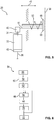
- a method 54 for operating the electromotive massage device 6 of the seat 4 is shown.
- the method 54 is carried out either by means of each of the control devices 40 of the massage drives 20 or by means of the control device 26. If the control device 26 is used, the method 54 is carried out individually for each of the massage drives 20, for example one after the other in time or simultaneously.
- a first step 56 which is carried out when the motor vehicle 2 is unlocked from the outside, the electric motor 30 of each of the massage drives 20 is energized and consequently the unbalance 36 or the stamp 46 is moved. For this purpose, an electrical voltage is applied to the electric motor 30 by means of the control device 40.
- the seat 4 is not occupied and consequently none of the sections 22.
- the torque of the electric motor 30 is determined.
- the current consumption of the electric motor 30 is determined, that is to say the electrical current flow that results from the application of the electrical voltage. If the massage drive 20 according to Figure 4 is configured, this results in an average current consumption which is averaged over several revolutions of the unbalance 36.
- the average value of the electrical current consumption is used here as a second reference value 60.
- the rope 44 is completely released by means of the rope pulley 42.
- the stamp plate 50 moves due to the spring 52 in the specific direction 48 until it rests against the seat cover 38 and is retained by the seat cover 38.
- the rope pulley 42 is moved in the opposite direction and the rope 44 is rolled up.
- the torque applied by means of the electric motor 30 is comparatively low.
- the torque increases. In other words, the torque changes.
- the position of the electric motor 30 at this point in time is used as the second reference value 60.
- the second reference value 60 corresponds to the extension of the spring 52 if the section 22 assigned to the respective massage drive is not occupied.
- a request to start the massage function of the electromotive massage device 6 is received via the bus system 8. This was created, for example, by means of the on-board computer 10, which has recorded a corresponding user input. In this case, the driver of the motor vehicle sits on the seat 4, so that at least parts of the sections 22 are occupied.
- the electric motor 30 is energized. Furthermore, the resulting torque of the electric motor 30 is detected by determining the electrical current consumption by it. If the massage drive 20 after the in Figure 4 is configured, the average electrical current consumption is determined for a specific time window, with several revolutions of the unbalance 36 being present, for example. The average electrical current consumption resulting in this way is used as a first reference value 66.
- the rope 44 is again completely released and thus the stamp plate 50 is pressed by means of the spring 52 against the seat cover 38. Following this, the rope 44 is again wound up by means of the rope pulley 42.
- the cable 44 is taut, the cable roller 42 is further rolled up against the force of the spring 52, so that the torque applied by means of the electric motor 30 increases and also its electrical current consumption.
- the present angular position of the electric motor 30, that is to say in particular the number of revolutions made after the rope 44 has been completely released, is used as the first reference value 66.
- the first reference value 66 is thus determined on the basis of a change in the torque 30 the first reference value 33 corresponds to the length of the rope 44, which is not rolled up on the rope pulley 42, and thus to the extension of the spring 52.
- the first reference value 66 is compared with the second reference value 60.
- the massage drive 20 according to Figure 4 is configured, checks whether the first reference value 66 is greater than the second reference value 60, that is to say whether the current consumption of the electric motor 30 is increased. If section 22 is occupied, i.e. if the user is in contact with section 22, it is necessary that unbalance 36 is moved not only against the seat cover but also against the driver's body, so that the torque required to rotate unbalance 36 increases is. Consequently, an assignment is concluded if the torque and thus the first reference value 66 are increased and larger than the second reference value 60. The allocation is made qualitatively, in particular whether section 22 is occupied or not.
- a subsequent sixth work step 70 the energization of the electric motor 30 is adjusted on the basis of the first reference value 66 and on the basis of the determined occupancy. In this case, the energization of the electric motor 30 is ended, provided the assigned section 22 is not occupied.
- current is applied in such a way that a speed of the electric motor 30 results in which the emission of acoustic waves is reduced.
- the rope 40 is only released up to the first reference value 66 during operation.
- the stamp 46 is moved against the seat cover 38.
- the rope 44 is rolled up again and the punch 46 is spaced from the seat cover 38.
- the rope 44 is released again up to the first reference value 66.
- the seat cover 38 is periodically moved outward, one Load on the electric motor 30 is reduced due to an idling.
- the time interval between the application of the stamp plate 50 to the seat cover 38 and the renewed spacing therefrom is also reduced.
- symmetrically arranged massage drives 20 are always supplied with the same current, which increases comfort.
- the determined occupancy is transmitted to the control unit 26 by means of the electrical lines 28, and the pattern by means of which the massage drives 20 are operated is adapted on the basis of the occupancy determined in each case.
- An adjustment path of the seat surface 24 and the backrest 40 is also changed by means of an electromotive drive, not shown, so that, for example, an unintentional movement, in particular into a position in which a safe sitting is no longer possible, is prevented.
- the occupancy of the seat 4 determined in this way is also compared with other sensors which are used, for example, to trigger an airbag. If there is a discrepancy, an error message in particular is output.
- the first reference value 66 is cyclically re-determined, for which the fourth, fifth and sixth work steps 64, 68, 70 are carried out every minute.
- the electric motors 30 are energized until a request to end the massage function is received in a seventh step 72 by means of the control device 26 via the bus system 8. This is transmitted to all control devices 40 and the operation of the respective electric motors 30 is ended.
- the massage drives 20 are installed within the molded parts 16, which are created in particular from a seat foam.
- the electrical current consumption of the electric motors 30 of the massage drives 20 changes as a function of the load on the seat surface 24 / the backrest 14, that is to say as a function of the assignment of the assigned section 22.
- the electrical current consumption of each of the electric motors 30 is dependent on the load on the respective one Seat structure.
- the occupancy is recognized, in particular seat recognition. If one of the sections 22 is not occupied, it will be used Section 22 associated massage drive 20 less energized or completely switched off.
- the method 54 is carried out, for example, by means of the control devices 40 or the control device 26, which thus functions as a control device.
- the intensity distribution by means of which areas of the seat 4 are moved by means of the massage drives 20, is adjusted on the basis of the detected occupancy by changing the energization of the electric motors 30.
- a preliminary characterization of the individual massage drives 20 in idle mode that is to say by determining the second reference value 60
- the massage drives 20 that are not used are, for example, switched off or operated at an acoustically advantageous working point, that is to say in particular at a lower intensity.
- a acoustically advantageous working point that is to say in particular at a lower intensity.
- symmetrically arranged massage drives 20 are energized immediately, which further increases comfort.
- an energy requirement is reduced and a system temperature is positively influenced.
- the load on the individual massage drives 20 is determined, and the massage is adapted to the occupant based on this information.
- a calibration run is carried out and the first reference value 66 is determined.
- the ropes 44 are released until the spring 52 could reach its theoretical end position, that is, the position that would arise if the respective section 22 was not loaded, and the Stamp 46 is retained by means of the seat cover 38.
- the theoretical end position suitably corresponds to the second reference value 60.
- the extension of the springs 52 is limited and the punch 46 comes to a different position. As a result, the rope 44 sags.
- the rope 44 is rolled up by means of the rope pulley 42.
- the electrical current required to drive the electric motor 30 is comparatively low.
- the electromotive massage device 6 is stored in particular as the first reference value 66. This results in the pressure distribution in the seat 4 via the spring hardness. As a result, it is possible to adapt the travel paths of the individual stamps 46 or to adapt an entire massage pattern.
- the measured information about the occupancy that is to say about the pressure distribution
- the massage function that is to say in particular to implement a specific pattern by means of the electric motors 30 or to switch off individual electric motors 30.
- the measured information about the occupancy (pressure distribution) on the seat surface 24 and / or on the backrest 14 is used to adapt different adjustment options of the seat 4, for example to change an adjustment speed of the backrest 14 or the seat surface 24.
- further settings of motor vehicle 2 are adapted to the user on the basis of the information.
- the electromotive massage device 6 it is possible to use the electromotive massage device 6 to obtain information about the user, such as, for example, his height, proportions, posture, sitting position and / or weight. For example, this information is stored. It is also possible to adapt the massage function to the user, which increases comfort. It is also possible to make any electrical seat adjustments adapt to the user, which in turn increases comfort. Further settings of motor vehicle 2 can also be adapted based on the determined data, which in turn leads to an increase in comfort. For example, the determination of the first and / or second reference value 60, 66 is determined in a calibration run, which is carried out, for example, automatically or depending on a user input.
Landscapes
- Engineering & Computer Science (AREA)
- Aviation & Aerospace Engineering (AREA)
- Transportation (AREA)
- Mechanical Engineering (AREA)
- Health & Medical Sciences (AREA)
- Rehabilitation Therapy (AREA)
- Pain & Pain Management (AREA)
- Physical Education & Sports Medicine (AREA)
- Epidemiology (AREA)
- Life Sciences & Earth Sciences (AREA)
- Animal Behavior & Ethology (AREA)
- General Health & Medical Sciences (AREA)
- Public Health (AREA)
- Veterinary Medicine (AREA)
- Massaging Devices (AREA)
- Seats For Vehicles (AREA)
- Percussion Or Vibration Massage (AREA)
Description
- Die Erfindung betrifft sowohl ein Verfahren zum Betrieb einer elektromotorischen Massageeinrichtung eines Sitzes, die einen Massageantrieb mit einem Elektromotor umfasst, als auch eine elektromotorische Massageeinrichtung eines Sitzes. Der Sitz ist jeweils bevorzugt ein Bestandteil eines Kraftfahrzeugs. Ferner betrifft die Erfindung einen Sitz eines Kraftfahrzeugs.
- Kraftfahrzeuge umfassen eine Anzahl an Nebenaggregaten, die nicht direkt dem Vortrieb des Kraftfahrzeugs dienen. Meist wird mittels dieser Nebenaggregate ein Komfort des Benutzers des Kraftfahrzeugs erhöht. Ein derartiges Nebenaggregat ist eine elektromotorische Massageeinrichtung, die ein Bestandteil eines Fahrzeugsitzes ist. Hierbei wird bei Aktivierung ein bestimmter Bereich des Fahrzeugsitzes periodisch verstellt, wie eine Rückenlehne oder ein Teil einer Rückenlehne. Aufgrund dessen wird eine Durchblutung eines Benutzers des Fahrzeugsitzes angeregt, weswegen eine Benutzung des Kraftfahrzeugs angenehmer ist. Auch können mittels des Kraftfahrzeugs auf diese Weise Fahrten mit einer vergleichsweise großen zeitlichen Dauer ausgeführt werden, ohne dass der Benutzer ermüdet.
- Kraftfahrzeugsitze weisen zudem üblicherweise eine Sitzbelegungserkennung auf. In Abhängigkeit der Sitzbelegungserkennung erfolgt beispielsweise eine Überwachung des korrekten Anlegens eines Gurtes und gegebenenfalls die Ausgabe eines Warntons. Zudem werden, um Kosten zu sparen, üblicherweise in einem Crash-Fall lediglich dann die Airbags aktiviert, sofern der Sitz belegt ist. Zur Erkennung, ob der Sitz belegt ist, wird üblicherweise ein Gewichtssensor verwendet, oder eine Deformation des Sitzes aufgrund der Belegung durch eine Person wird erfasst. In einer Alternative hierzu wird eine kapazitive Sensorelektrode herangezogen, mittels derer im Bereich des Sitzes ein elektromagnetisches Feld erstellt und überwacht wird. Im Betrieb wird dabei eine Änderung einer Dielektrizitätskonstante aufgrund einer Veränderung der Kapazität erfasst. Die Änderung der Dielektrizitätskonstanten rührt hierbei von der Anwesenheit einer Person im Bereich des Sitzes her. Sofern somit eine Änderung der Kapazität erfasst wird, ist auch eine Belegung des Sitzes erkannt. Aus der
DE102015204492 ist ein Verfahren bekannt einen Sitz mit Massageelementen auszustatten und diese als Sensoren zur Sitzbelegungserkennung einzusetzen. - Der Erfindung liegt die Aufgabe zugrunde, ein besonders geeignetes Verfahren zum Betrieb einer elektromotorischen Massageeinrichtung eines Sitzes sowie eine besonders geeignete elektromotorische Massageeinrichtung eines Sitzes als auch einen besonders geeigneten Sitz eines Kraftfahrzeugs anzugeben, wobei insbesondere Herstellungskosten verringert und vorzugsweise eine Lebensdauer und/oder ein Komfort erhöht und geeigneterweise ein akustischer Eindruck verbessert ist.
- Hinsichtlich des Verfahrens wird diese Aufgabe durch die Merkmale des Anspruchs 1, hinsichtlich der elektromotorischen Massageeinrichtung durch die Merkmale des Anspruchs 7 und hinsichtlich des Sitzes durch die Merkmale des Anspruchs 10 erfindungsgemäß gelöst. Vorteilhafte Weiterbildungen und Ausgestaltungen sind Gegenstand der jeweiligen Unteransprüche.
- Das Verfahren dient dem Betrieb einer elektromotorischen Massageeinrichtung. Die elektromotorische Massageeinrichtung ist ein Bestandteil eines Sitzes, und bestimmungsgemäß wird mittels der elektromotorischen Massageeinrichtung eine Massagefunktion ausgeführt. Hierbei wird beispielsweise ein Bestandteil des Sitzes, wie die Sitzfläche oder eine Lehne, bewegt, insbesondere periodisch. Der Sitz und somit die elektromotorische Massageeinrichtung sind bevorzugt ein Bestandteil eines Kraftfahrzeugs, und der Sitz ist beispielsweise ein Fahrersitz oder ein Beifahrersitz.
- Die elektromotorische Massageeinrichtung weist einen Massageantrieb mit einem Elektromotor auf. Mittels des Elektromotors ist insbesondere ein weiterer Bestandteil des Massageantriebs angetrieben, mittels dessen eine Massagefunktion durchgeführt wird. Beispielsweise wird mittels des weiteren Bestandteils, beispielsweise ein Vibrationselement, eine Unwucht oder ein Stempel, ein Bestandteil des Sitzes ausgebeult, insbesondere periodisch. Der weitere Bestandteil ist hierfür geeignet, zweckmäßigerweise vorgesehen und eingerichtet. Der Elektromotor ist beispielsweise ein bürstenbehafteter Kommutatormotor. Besonders bevorzugt jedoch ist der Elektromotor bürstenlos ausgestaltet und insbesondere ein bürstenloser Gleichstrommotor (BLDC). Beispielsweise ist der Elektromotor ein Asynchronmotor, bevorzugt jedoch ein Synchronmotor. Der Elektromotor ist insbesondere dreiphasig, wobei die einzelnen Phasen beispielsweise in einer Dreiecks- oder Sternschaltung miteinander verschaltet sind.
- Das Verfahren sieht vor, dass in einem Arbeitsschritt der Elektromotor bestromt wird. Hierfür wird beispielsweise eine bestimmte elektrische Spannung an den Elektromotor angelegt. Insbesondere ist die elektrische Spannung vorgegeben. Alternativ hierzu wird beispielsweise ein elektrischer Stromfluss zu dem Elektromotor eingestellt. Insbesondere erfolgt die Bereitstellung der elektrischen Spannung / des elektrischen Stroms mittels eines Umrichters, der beispielsweise eine Brückenschaltung, wie eine B6-Schaltung aufweist.
- In einem weiteren Arbeitsschritt wird das Drehmoment des Elektromotors erfasst. Mit anderen Worten wird das Drehmoment des Elektromotors bestimmt, welches sich aufgrund der Bestromung ergibt. Anhand des Drehmoments wird ein erster Referenzwert ermittelt. Der erste Referenzwert weist als mögliche Wertemenge beispielsweise lediglich zwei Werte auf. Insbesondere wird hierbei der eine Wert für den ersten Referenzwert herangezogen, wenn das Drehmoment oberhalb einer bestimmten Schwelle liegt und ansonsten der andere Wert. Alternativ hierzu ist der Wertbereich des ersten Referenzwerts vergrößert und/oder insbesondere diskret. Alternativ hierzu ist der Wertbereich des ersten Referenzwerts kontinuierlich. Zumindest besteht ein funktioneller Zusammenhang zwischen dem ersten Referenzwert und dem Drehmoment, wobei beispielsweise eine ein-eindeutige Zuordnung erfolgt. Beispielsweise wird als erster Referenzwert das erfasste Drehmoment herangezogen.
- In einem weiteren Arbeitsschritt wird anhand des ersten Referenzwerts eine Belegung zumindest eines Abschnitts des Sitzes ermittelt. Insbesondere entspricht der Abschnitt vollständig oder zumindest zum Teil dem Bestandteil des Sitzes, welcher bei Bestromung des Elektromotors bewegt wird. Mit anderen Worten wird aus dem ersten Referenzwert auf die Belegung des Abschnitts geschlossen. Die Belegung ist insbesondere eine Belastung des Abschnitts aufgrund der Anwesenheit einer Person. Mit anderen Worten wird ermittelt, ob die Person auf dem Abschnitt sitzt oder an diesen angelehnt ist, also ob die Person, insbesondere ein Fahrer des Kraftfahrzeugs, in mechanischem Kontakt mit dem Abschnitt ist. Somit wird anhand des Drehmoments des Elektromotors bzw. anhand des hieraus abgeleiteten ersten Referenzwerts die Belegung des Abschnitts des Sitzes ermittelt. Sofern zur Verbringung des Abschnitts ein vergleichsweise hohes Drehmoment erforderlich ist und somit vorherrscht, ist eine Belegung des Abschnitts wahrscheinlich. Sofern der Abschnitt nicht belegt ist, ist lediglich ein vergleichsweise geringes Drehmoment erforderlich. Folglich ist es daher ermöglicht mittels des Drehmoments und daher auch mittels des ersten Referenzwerts die Belegung des Abschnitts zu bestimmen. Infolgedessen sind keine weiteren Sensoren oder dergleichen erforderlich, weswegen Herstellungskosten verringert sind. Beispielsweise wird die Belegung binär ermittelt, also ermittelt, ob eine Belegung vorhanden oder nicht vorhanden ist. Alternativ hierzu wird die Belegung qualitativ ermittelt, also insbesondere, mit wie viel Druck/Gewicht der Abschnitt belastet ist.
- Zweckmäßigerweise weist die elektromotorische Massageeinrichtung mehrere derartige Massageantriebe auf, die unterschiedlichen Abschnitten des Sitzes zugeordnet sind. Somit ist es ermöglicht, die Position des Benutzers auf dem Sitz mittels der Massageantriebe zu bestimmen. Insbesondere wird anhand der Belegung eine Sitzposition des Benutzers auf dem Sitz bestimmt. In Abhängigkeit der ermittelten (Sitz-)Position des Benutzers wird beispielsweise eine mögliche Verstellbewegung des Sitzes begrenzt, insbesondere eine elektromotorische Verstellung des Sitzes, z.B. eine elektromotorische Verstellung der Lehne des Sitzes, also deren Neigungswinkel bezüglich der Sitzfläche, oder einer transversalen Verbringung des Sitzes. Alternativ oder in Kombination hierzu wird anhand der ermittelten Sitzposition eine weitere Einstellung des Kraftfahrzeugs vorgenommen, sofern die elektromotorische Massageeinrichtung ein Bestandteil des Kraftfahrzeugs ist. Beispielsweise wird eine Einstellung einer etwaige Klimaanlage, eines Audio-Systems oder eines Gurtes / Gurtantriebs beeinflusst. Folglich ist ein Komfort weiter erhöht.
- Das Drehmoment des Elektromotors wird beispielsweise anhand der Stromaufnahme bestimmt. Mit anderen Worten wird der erste Referenzwert aus der Stromaufnahme ermittelt. Beispielsweise wird der elektrische Stromfluss zu dem Elektromotor erfasst und hieraus das Drehmoment abgeleitet. Beispielsweise wird hierfür ein Motormodell herangezogen. Alternativ hierzu wird als Drehmoment bereits der elektrische Strom direkt verwendet, was eine Berechnung vereinfacht. Aufgrund der Bestimmung der Stromaufnahme ist lediglich ein vergleichsweise kostengünstiger Sensor erforderlich, der beispielsweise vorhanden ist, insbesondere sofern der Elektromotor geregelt wird. Infolgedessen sind Herstellungskosten reduziert.
- Vorzugsweise wird zur Ermittlung der Belegungen der erste Referenzwert mit einem zweiten Referenzwert verglichen. Bei dem Vergleich wird beispielsweise überprüft, ob der erste Referenzwert größer als der zweite Referenzwert oder umgekehrt ist. Sofern der erste Referenzwert größer bzw. kleiner als der zweite Referenzwert ist, ist insbesondere die Belegung erkannt. Der zweite Referenzwert ist beispielsweise anhand eines theoretischen Models vorgegeben und/oder anhand des verwendenden Elektromotors vorgegeben und/oder ermittelt. Besonders bevorzugt jedoch wird der zweite Referenzwert aus einem Drehmoment des Elektromotors ermittelt, das sich ergibt, wenn der Abschnitt nicht belegt ist. Mit anderen Worten wird zunächst sichergestellt, dass der Abschnitt nicht belegt ist und der Elektromotor im Anschluss bestromt. Das resultierende Drehmoment des Elektromotors wird erfasst und hieraus der zweite Referenzwert ermittelt. Beispielsweise wird der zweite Referenzwert in der gleichen Weise ermittelt, wie der erste Referenzwert. Mit anderen Worten wird die gleiche Rechenvorschrift zur Ermittlung des zweiten Referenzwerts herangezogen wie zur Ermittlung des ersten Referenzwerts. Zum Beispiel wird das Drehmoment als zweiter Referenzwert herangezogen. Vorzugsweise wird zusätzlich ein Toleranzwert oder dergleichen verwendet, sodass der zweite Referenzwert in der gleichen Weise wie der erste Referenzwert ermittelt wird und zu diesem Ergebnis der Toleranzwert addiert wird. Dieses Ergebnis wird als zweiter Referenzwert verwendet.
- Geeigneterweise erfolgt die Ermittlung des zweiten Referenzwerts und somit die Sicherstellung, dass der Abschnitt nicht belegt ist, wenn das Kraftfahrzeug verschlossen ist und beispielsweise von außerhalb abgeschlossen wurde. Alternativ hierzu wird beispielsweise direkt nach einem Entriegeln des Kraftfahrzeugs von Außen der zweite Referenzwert ermittelt. In einer weiteren Alternative wird der zweite Referenzwert beispielsweise nach Fertigung der elektromotorischen Massageeinrichtung und beispielsweise nach Fertigung des Kraftfahrzeugs ermittelt, insbesondere auf einem Prüfstand. Der zweite Referenzwert wird beispielsweise in einem Speicher der elektromotorischen Massageeinrichtung hinterlegt. Alternativ hierzu wird der zweite Referenzwert neu ermittelt, beispielsweise zyklisch. Auf diese Weise wird beispielsweise ein Verschleiß oder dergleichen berücksichtigt.
- Beispielsweise wird der erste Referenzwert anhand einer Änderung des Drehmoments des Elektromotors ermittelt. Mit anderen Worten wird zunächst die Änderung des Drehmoments ermittelt und anhand derer der erste Referenzwert bestimmt. Insbesondere wird auf diese Weise bestimmt, wann sich das Drehmoment des Elektromotors ändert. Hierbei wird insbesondere der Drehmomentverlauf oder eine hierzu korrespondierende Größe ermittelt. Wenn sich das Drehmoment ändert, ist beispielsweise der erste Referenzwert bestimmt. Dieser korrespondiert geeigneterweise zu einer bestimmten Winkelstellung des Elektromotors. Insbesondere sofern mittels des Elektromotors ein Stempel oder dergleichen angetrieben wird, ändert sich das Drehmoment, wenn der Stempel gegen einen Bezug des Sitzes verfahren wird und diesen beispielsweise nach außen ausbeult. Daher tritt eine Erhöhung des Drehmoments aufgrund des mechanischen Widerstandes auf, der zumindest mittels des Bezugs und beispielsweise aufgrund der Belegung vorhanden ist. Mit anderen Worten wird in diesem Fall der Stempel gegen den Benutzer verfahren. Dieser Punkt wird beispielsweise als erster Referenzwert herangezogen oder zumindest die Winkelstellung des Elektromotors. Somit wird bestimmt, ab welcher Winkelstellung des Elektromotors das Drehmoment zur Verbringung des Bezugs des Sitzes oder zumindest einer Oberfläche des Sitzes aufgebracht werden muss. Sofern der Abschnitt belegt ist, ist dieser Punkt in Richtung des Elektromotors versetzt, zumindest wenn der Sitz zumindest teilweise nachgiebig ausgestaltet ist. Folglich wird aufgrund der Winkelstellung des Elektromotors, bei dem der Anstieg des Drehmoments erfolgt, auf die Position der Oberfläche des Abschnitts geschlossen und somit darauf, ob dieser belegt ist.
- Zweckmäßigerweise wird die Bestromung des Elektromotors anhand des ersten Referenzwerts angepasst. Vorzugsweise wird die Bestromung des Elektromotors angepasst, wenn keine Belegung des Abschnitts ermittelt ist. Insbesondere wird die Bestromung des Elektromotors beendet, was einen Energiebedarf verringert. Auch ist auf diese Weise eine Erwärmung des Elektromotors ausgeschlossen, sodass eine Lebensdauer erhöht ist. Alternativ hierzu wird zumindest der Elektromotor bei einer Drehzahl betrieben, bei der das Aussenden von akustischen Wellen verringert ist. Somit ist ein Komfort erhöht und ein akustischer Eindruck verbessert. Geeigneterweise wird die Bestromung des Elektromotors verstärkt, wenn eine Belegung vorherrscht, die jedoch vergleichsweise gering ist. Falls die Belegung vorhanden und vergleichsweise stark ist, wird beispielsweise die Bestromung verringert, um eine Überlastung des Elektromotors zu verringern. Insbesondere wird ein Bewegungsmuster des Elektromotors angepasst, insbesondere sofern die Belegung qualitativ bestimmt / ermittelt wird. Somit ist ein Komfort weiter erhöht.
- Beispielsweise wird der Referenzwert mittels einer Kalibrierfahrt ermittelt. Hierfür wird beispielsweise nach einer Aktivierung der elektromotorischen Massageeinrichtung der erste Referenzwert ermittelt und somit die Belegung. Der erste Referenzwert und die auf diese Weise ermittelte Belegung werden beispielsweise während des Betriebs der elektromotorischen Massageeinrichtung nicht nochmals ermittelt und sind somit während des gesamten Betriebs konstant. Beispielsweise wird der erste Referenzwert und somit die Belegung ermittelt, wenn eine Benutzereingabe vorliegt. Geeigneterweise korrespondiert die Benutzereingabe zu einer Aktivierung der elektromotorischen Massageeinrichtung. Besonders bevorzugt wird der erste Referenzwert zyklisch erneut ermittelt, beispielsweise alle 5 Sekunden, alle 10 Sekunden, jede Minute, alle 5 Minuten oder alle 10 Minuten. Somit wird die Belegung des Abschnitts ebenfalls zyklisch neu ermittelt, und es ist somit insbesondere möglich, die Bestromung des Elektromotors und/oder weiterer etwaiger Funktionen des etwaigen Kraftfahrzeugs in Abhängigkeit der aktuellen Belegung zu beeinflussen.
- Die elektromotorische Massageeinrichtung ist ein Bestandteil eines Sitzes und beispielsweise ein Bestandteil eines Kraftfahrzeugs. Insbesondere ist die elektromotorische Massageeinrichtung ein Bestandteil eines Fahrersitzes oder eines Beifahrersitzes. Die elektromotorische Massageeinrichtung weist einen Massageantrieb mit einem Elektromotor sowie eine Steuereinrichtung auf. Die elektromotorische Massageeinrichtung dient dem Bereitstellen einer Massagefunktion. Zweckmäßigerweise ist der Massageantrieb vorgesehen und eingerichtet, einen Abschnitt des Sitzes, beispielweise eine Lehne, eine Sitzfläche oder zumindest einen Teil hiervon, zu verstellen, insbesondere periodisch. Beispielsweise wird der Abschnitt ausgebeult.
- Die elektromotorische Massageeinrichtung ist gemäß einem Verfahren betrieben, bei dem der Elektromotor bestromt wird, und bei dem ein Drehmoment des Elektromotors erfasst sowie hieraus ein erster Referenzwert ermittelt wird. Anhand des ersten Referenzwerts wird eine Belegung zumindest des Abschnitts des Sitzes ermittelt. Beispielsweise wird die elektromotorische Massageeinrichtung verwendet, um das Verfahren durchzuführen. Zweckmäßigerweise wird bei Betrieb des Elektromotors der Abschnitt oder zumindest ein Bereich des Abschnitts mittels des Elektromotors bewegt. Insbesondere ist die Steuereinrichtung geeignet, vorzugsweise vorgesehen und eingerichtet, das Verfahren durchzuführen. Die Steuereinrichtung ist beispielsweise eine zentrale Steuereinrichtung (Steuergerät) der elektromotorischen Massageeinrichtung oder ein Bestandteil des Massageantriebs und geeigneterweise an dem Elektromotor befestigt. Zum Beispiel dient die Steuereinrichtung zusätzlich der Einstellung der Bestromung des Elektromotors. Vorzugsweise umfasst die elektromotorische Massageeinrichtung zusätzlich ein zentrales Steuergerät, mittels dessen beispielsweise eine Kommunikation mit weiteren Bestandteilen, beispielsweise einer Eingabevorrichtung und/oder einem Bussystem erfolgt, insbesondere sofern die Massageeinrichtung ein Bestandteil des Kraftfahrzeugs ist.
- Der Massageantrieb weist beispielsweise eine mittels des Elektromotors angetriebene Unwucht auf. Aufgrund dieser Unwucht wird geeigneterweise der Massageantrieb in eine Bewegung versetzt, wobei diese Bewegung periodisch ist. Hierbei ist der Massageantrieb im Montagezustand zweckmäßigerweise mit einem weiteren Bestandteil des Sitzes gekoppelt, beispielsweise einer etwaigen Lehne oder Sitzfläche, so dass mittels der Unwucht der jeweilige Bestandteil bewegt, insbesondere ausgebeult, wird.
- Zweckmäßigerweise weist der Massageantrieb einen in eine vorgegebene Richtung beweglichen und federbelasteten Stempel auf. Hierbei ist der Stempel insbesondere mittels der Feder in die vorgegebene Richtung belastet. Die vorgegebene Richtung ist zweckmäßigerweise auf den Abschnitt zu gerichtet. Geeigneterweise ist die vorgegebene Richtung in Richtung eines Bezugs des Sitzes gerichtet und insbesondere senkrecht zu diesem. Die Feder ist beispielsweise eine Schraubenfeder oder ein pneumatisches Federelement. Vorzugsweise ist die Feder eine Druckfeder. Die Position des Stempels in der vorgegebenen Richtung ist mittels eines Seils begrenzt. Beispielsweise ist das Seil an dem Stempel angebunden. Zumindest wird mittels des Seils die Bewegung des Stempels in der vorgegebenen Richtung begrenzt. Hierbei ist beispielsweise auch eine weitere Begrenzung der Position des Stempels in der vorgegebenen Bewegung möglich, beispielsweise aufgrund der Belegung des Abschnitts. Zumindest wird mittels des Seils eine theoretisch maximale Position des Stempels in der vorgegebenen Richtung vorzugsweise begrenzt.
- Insbesondere wirkt hierbei das Seil entgegen der Kraftrichtung der Feder. Somit wird mittels des Seils entgegen der Federkraft der Stempel verbracht und in dieser Position mittels des Seils gehalten. Das Seil ist beispielsweise aus einem Kunststoff gefertigt. Insbesondere ist das Seil biegeschlaff. Alternativ hierzu ist das Seil starr und beispielsweise nach Art einer Zahnstange gefertigt. Das Seil ist in Wirkverbindung mit dem Elektromotor. Beispielsweise ist das Seil zumindest teilweise auf einer Seilrolle aufgewickelt, die mittels des Elektromotors angetrieben ist. Somit wird bei der Bestromung des Elektromotors mittels des Seils die Position des Stempels in der vorgegebenen Richtung eingestellt.
- Beispielsweise korrespondiert der erste Referenzwert zur Ausdehnung der Feder. Die Ausdehnung der Feder korrespondiert insbesondere zur Ausdehnung des Seils. Beispielsweise korrespondiert der erste Referenzwert zur Ausdehnung der Feder, wenn das Seil von einem schlaffen in einen gespannten Zustand übergeht. Dieser Wechsel des Zustands des Seils wird insbesondere anhand einer Zunahme des Drehmoments ermittelt. Sofern der Stempel beispielsweise an dem Abschnitt anliegt, ist dessen Position somit mittels des Abschnitts bestimmt. In diesem Fall ist das Seil beispielsweise zwischen dem Stempel und der etwaigen Seilrolle nicht gespannt.
- Zur Bestimmung der Belegung wird geeigneterweise zunächst das Seil im Wesentlichen vollständig freigegeben und die Position des Stempels somit mittels des Abschnitts bestimmt. Mit anderen Worten liegt der Stempel geeigneterweise an dem Abschnitt an, und das Seil ist schlaff. Der Elektromotor wird im Anschluss angetrieben und das Seil zumindest teilweise auf die Seilrolle aufgerollt. Wenn das Seil gespannt ist, ist es erforderlich mittels des Elektromotors ein größeres Drehmoment auf die Seilrolle und somit eine größere Kraft aufzuwenden, die entgegen der Federkraft wirkt, um den Stempel von dem Abschnitt zu beabstanden. Die Ausdehnung der Feder bzw. des Seils bei diesem Anstieg des Drehmoments wird zweckmäßigerweise als erster Referenzwert herangezogen. Insbesondere wird hierbei der erste Wert mit dem zweiten Referenzwert verglichen, der insbesondere ermittelt wird, wenn der Abschnitt nicht belegt ist. Sofern die Ausdehnung der Feder kleiner als die Ausdehnung der Feder im unbelegtem Zustand ist, also insbesondere sofern der erste Referenzwert kleiner als der zweite Referenzwert ist, ist insbesondere die Belegung ermittelt.
- Der Sitz ist ein Bestandteil eines Kraftfahrzeugs und weist eine elektromotorische Massageeinrichtung auf. Der Sitz ist somit ein Fahrzeugsitz und zweckmäßigerweise ein Fahrersitz, also der Sitz, der von einem Führer des Kraftfahrzeugs eingenommen wird. Der (Fahrzeug-)Sitz umfasst insbesondere eine Sitzfläche und geeigneterweise eine Lehne. Die Sitzfläche und/oder die Lehne weisen zweckmäßigerweise ein Formteil aus Kaltschaum auf, welcher mittels eines Überzugs versehen ist, beispielsweise einem Stoff oder Leder. Die elektromotorische Massageeinrichtung weist einen Massageantrieb mit einem Elektromotor auf. Der Massageantrieb ist zweckmäßigerweise in einer Aussparung innerhalb des Formteils aus Kaltschaum angeordnet, und bei Betrieb wird geeigneterweise der Überzug, also insbesondere der Stoff oder das Leder, ausgebeult, insbesondere periodisch. Die elektromotorische Massageeinrichtung umfasst ferner eine Steuereinrichtung und ist gemäß einem Verfahren betrieben, bei dem der Elektromotor bestromt wird, und ein Drehmoment des Elektromotors erfasst und hieraus ein erster Referenzwert ermittelt wird. Anhand des ersten Referenzwerts wird eine Belegung zumindest eines Abschnitts des Sitzes ermittelt.
- Die im Zusammenhang mit dem Verfahren zum Betrieb der elektromotorischen Massageeinrichtung erläuterten Weiterbildungen und Vorteile sind sinngemäß auch auf die elektromotorische Massageeinrichtung/Verwendung und/oder den Sitz zu übertragen und umgekehrt.
- Nachfolgend werden Ausführungsbeispiele der Erfindung anhand einer Zeichnung näher erläutert. Darin zeigen:
- Fig. 1
- schematisch vereinfacht ein Kraftfahrzeug mit einem eine elektromotorische Massageeinrichtung umfassenden Sitz,
- Fig. 2
- perspektivisch den Sitz mit der elektromotorischen Massageeinrichtung,
- Fig. 3
- perspektivisch die elektromotorischen Massageeinrichtung mit mehreren Massageantrieben,
- Fig. 4
- schematisch einen der Massageantriebe,
- Fig. 5
- schematisch eine weitere Ausführungsform des Massageantriebs, und
- Fig. 6
- ein Verfahren zum Betrieb der elektromotorischen Massageeinrichtung.
- Einander entsprechende Teile sind in allen Figuren mit den gleichen Bezugszeichen versehen.
- In
Fig. 1 ist schematisch vereinfacht ein Kraftfahrzeug 2 mit einem (Fahrzeug)Sitz 4 gezeigt. Der Fahrzeugsitz 4 umfasst eine elektromotorische Massageeinrichtung 6, die mit einem BUS-System 8 signaltechnisch verbunden ist. Das BUS-System 8 basiert auf dem CAN-Standard, und ein Bordcomputer 10 sowie ein weiterer BUS-Teilnehmer 12 sind jeweils ein Bestandteil des BUS-Systems 8. Mittels des Bordcomputers 10 werden Anforderungen an die elektromotorische Massageeinrichtung 6 sowie den weiteren BUS-Teilnehmer 12 übertragen. Auch findet ein Austausch von Betriebsdaten über das BUS-System 8 statt. - In
Fig. 2 ist der als Fahrersitz ausgestaltete Sitz 4 perspektivisch, jedoch ohne einen Sitzbezug, dargestellt. Der (Fahrer-)Sitz 4 umfasst eine Rückenlehne 14, welche ein Formteil 16 aus einem Kaltschaum umfasst, in das eine der Stabilisierung dienende Haltestruktur 18 aus einem Metall eingebettet ist. Das Formteil 16 weist eine Anzahl an Ausnehmungen auf, wobei innerhalb jeder jeweils ein Massageantrieb 20 der elektromotorischen Massageeinrichtung 6 angeordnet ist. Die Massageantriebe 20 sind zueinander beabstandet, und jedem der Massageantriebe 20 ist ein Abschnitt 22 zugeordnet. Die Abschnitte 22 korrespondieren zu den Bereichen des Sitzes 4, die bei Betrieb des jeweils zugeordneten Massageantriebs 20 ausgebeult oder zumindest bewegt werden. Der Sitz 4 weist ferner eine Sitzfläche 24 auf, der ebenfalls nicht näher dargestellte Massageantriebe zugeordnet sind. - In
Fig. 3 ist die elektromotorischen Massageeinrichtung 6 gezeigt, die ein Steuergerät 26 sowie die insgesamt acht Massageantriebe 20 aufweist. De Massageantriebe 20 sind jeweils mittels elektrischen Leitungen 28 mit dem Steuergerät 26 elektrisch und signaltechnisch gekoppelt. - In
Fig. 4 ist eine erste Ausführungsform eines der Massageantriebe 20 dargestellt, wobei alle Massageantriebe 20 beispielsweise zueinander baugleich sind. Der Massageantrieb 20 weist einen Elektromotor 30 mit einem Gehäuse 32 aus einem metallischen Blech auf. An einer Welle 34 des Elektromotors 30 ist eine Unwucht 36 angebunden, die somit mittels des Elektromotors 32 angetrieben ist. Bei einer Rotationsbewegung des Elektromotors 32 und somit einer Rotationsbewegung der Unwucht 36 wird der Massageantrieb 20 in eine rhythmische Bewegung versetzt, sodass der zugeordnete Abschnitt 22 vibriert. Alternativ oder in Kombination hierzu wird ein Sitzbezug 38 des Sitzes 4 mittels der Unwucht 36 periodisch ausgebeult. Der Massageantrieb 20 umfasst eine Steuereinrichtung 40, mittels derer eine Bestromung des Elektromotors 32 erfolgt. Die Steuereinrichtung 40 ist elektrisch mit der elektrischen Leitung 28 kontaktiert, und bei Betrieb werden zwischen dem Steuergerät 26 und der Steuereinrichtung 40 mittels der elektrischen Leitung 28 Daten ausgetauscht, wobei mittels einer weiteren Ader der elektrischen Leitung 28 ein elektrischer Stromfluss zu der Steuereinrichtung 40 bereitgestellt wird. - In
Figur 5 ist eine weitere Ausgestaltungsform des Massageantriebs 20 schematisch vereinfacht gezeigt. Der Elektromotor 30, der ein bürstenloser Gleichstrommotor (BLDC) ist, die Steuereinrichtung 40 und deren Verbindung mit der elektrischen Leitung 28 sind nicht abgeändert. An der Welle 34 ist eine Seilrolle 42 drehfest angebunden, auf der ein Seil 44 zumindest teilweise aufgerollt ist. Das Seil 44 ist ferner an einem Stempel 46 befestigt, welcher in eine bestimmte Richtung 48 mittels einer nicht näher dargestellten Führung beweglich ist. Senkrecht zur bestimmten Richtung 48 ist eine Stempelplatte 50 des Stempels 46 angeordnet, die im Wesentlichen parallel zu dem Sitzbezug 38 angeordnet ist. Der Stempel 46 ist mittels einer Druckfeder 52 in Form einer Schraubenfeder belastet, sodass die Stempelplatte 50 mittels der Feder 52 von dem Elektromotor 30 gegen den Sitzbezug 38 in die vorgegebene Richtung 48 gedrückt wird. Hierfür ist die Feder 52 an einem ortsfesten Bauteil des Sitzes 4 abgestützt. - Die Position des Stempels 46 ist mittels des Seils 44 begrenzt, und mittels des Elektromotors 30 kann der Stempel 46 entgegen der mittels der Feder 42 aufgebrachten Kraft in der vorgegebenen Richtung 48 bewegt werden. Mittels Abrollen des Seils 44 von der Seilrolle 42 wird der Stempel 46, und im Speziellen die Stempelplatte 50, gegen den Sitzbezug 38 mittels der Feder 52 verbracht. Bei einem vergleichsweise schnellen Abrollen des Seils 44 wird somit der Sitzbezug 38 ausgebeult.
- In
Figur 6 ist ein Verfahren 54 zum Betrieb der elektromotorischen Massageeinrichtung 6 des Sitzes 4 gezeigt. Das Verfahren 54 wird entweder mittels jeder der Steuereinrichtungen 40 der Massageantriebe 20 oder mittels des Steuergeräts 26 ausgeführt. Sofern das Steuergerät 26 verwendet wird, wird das Verfahren 54 für jeden der Massageantriebe 20 einzeln durchgeführt, beispielsweise zeitlich nacheinander oder gleichzeitig. In einem ersten Arbeitsschritt 56, der ausgeführt wird, wenn das Kraftfahrzeug 2 von außen entriegelt wird, wird der Elektromotor 30 jedes der Massageantriebe 20 bestromt und folglich die Unwucht 36 bzw. der Stempel 46 bewegt. Hierfür wird mittels der Steuereinrichtung 40 an dem Elektromotor 30 eine elektrische Spannung angelegt. Somit ist im ersten Arbeitsschritt 56 der Sitz 4 nicht belegt und folglich auch keiner der Abschnitte 22. - In einem sich anschließenden zweiten Arbeitsschritt 58 wird das Drehmoment des Elektromotors 30 bestimmt. Hierfür wird die Stromaufnahme des Elektromotors 30 bestimmt, also der elektrische Stromfluss, der sich aufgrund des Anlegens der elektrischen Spannung ergibt. Sofern der Massageantrieb 20 gemäß
Figur 4 ausgestaltet ist, ergibt sich hierbei eine durchschnittliche Stromaufnahme, die über mehrere Umdrehungen der Unwucht 36 gemittelt ist. Der durchschnittliche Wert der elektrischen Stromaufnahme wird hierbei als ein zweiter Referenzwert 60 herangezogen. - Sofern der Massageantrieb 20 gemäß
Figur 5 ausgeführt ist, wird das Seil 44 mittels der Seilrolle 42 vollständig freigegeben. Infolgedessen bewegt sich die Stempelplatte 50 aufgrund der Feder 52 in die bestimmte Richtung 48 bis diese an dem Sitzbezug 38 anliegt und durch den Sitzbezug 38 zurückgehalten wird. Im Anschluss hieran wird die Seilrolle 42 in die umgekehrte Richtung bewegt und das Seil 44 aufgerollt. Solange dieses durchhängt, ist das mittels des Elektromotors 30 aufgebrachte Drehmoment vergleichsweise gering. Sobald das Seil 44 gestrafft ist und den Stempel 46 entgegen der Kraft der Feder 52 in die bestimmte Richtung 48 bewegt, steigt das Drehmoment an. Mit anderen Worten ändert sich das Drehmoment. Die an diesem Zeitpunkt vorliegende Stellung des Elektromotors 30 wird als der zweite Referenzwert 60 herangezogen. Somit korrespondiert der zweite Referenzwert 60 zur Ausdehnung der Feder 52, sofern der dem jeweiligen Massageantrieb zugeordnete Abschnitt 22 nicht belegt ist. - In einem dritten Arbeitsschritt 62 wird eine Aufforderung zum Starten der Massagefunktion der elektromotorischen Massageeinrichtung 6 über das Bus-System 8 empfangen. Diese wurde beispielsweise mittels des Bordcomputers 10 erstellt, welcher eine entsprechende Benutzereingabe erfasst hat. In diesem Fall sitzt der Fahrer des Kraftfahrzeugs auf dem Sitz 4, sodass zumindest Teile der Abschnitte 22 belegt sind. In einem sich anschließenden vierten Arbeitsschritt 64 wird der Elektromotor 30 bestromt. Ferner wird das resultierende Drehmoment des Elektromotors 30 erfasst, in dem die elektrische Stromaufnahme durch diesen bestimmt wird. Sofern der Massageantrieb 20 nach der in
Figur 4 gezeigten Variante ausgestaltet ist, wird die durchschnittliche elektrische Stromaufnahme für ein bestimmtes Zeitfenster ermittelt, wobei hierbei beispielsweise mehrere Umdrehungen der Unwucht 36 vorliegen. Die sich auf diese Weise ergebende durchschnittliche elektrische Stromaufnahme wird als ein erster Referenzwert 66 herangezogen. - Sofern der Massageantrieb 20 gemäß der in
Figur 5 dargestellten Variante ausgestaltet ist, wird wiederum das Seil 44 vollständig freigegeben und somit die Stempelplatte 50 mittels der Feder 52 gegen den Sitzbezug 38 gedrückt. Im Anschluss hieran wird wiederum das Seil 44 mittels der Seilrolle 42 aufgewickelt. Wenn das Seil 44 straff gespannt ist, erfolgt ein weiteres Aufrollen auf die Seilrolle 42 entgegen der Kraft der Feder 52, sodass das mittels des Elektromotors 30 aufgebrachte Drehmoment ansteigt und ebenfalls dessen elektrische Stromaufnahme. Die hierbei vorliegende Winkelstellung des Elektromotors 30, also insbesondere die Anzahl der zurückgelegten Umdrehungen nach vollständiger Freigabe des Seils 44, wird als der erste Referenzwert 66 herangezogen. Somit wird der erste Referenzwert 66 anhand einer Änderung des Drehmoments 30 ermittelt und der erste Referenzwert 33 korrespondiert zur Länge des Seils 44, welches nicht auf der Seilrolle 42 aufgerollt ist, und somit zur Ausdehnung der Feder 52. - In einem sich anschließenden fünften Arbeitsschritt 68 wird der erste Referenzwert 66 mit dem zweiten Referenzwert 60 verglichen. Hierbei wird, sofern der Massageantrieb 20 gemäß
Figur 4 ausgestaltet ist, überprüft, ob der erste Referenzwert 66 größer als der zweite Referenzwert 60 ist, also ob die Stromaufnahme des Elektromotors 30 vergrößert ist. Sofern der Abschnitt 22 belegt ist, also sofern der Benutzer an dem Abschnitt 22 anliegt, ist es erforderlich, dass die Unwucht 36 nicht nur gegen den Sitzbezug sondern auch gegen den Körper des Fahrers bewegt wird, sodass das benötigte Drehmoment zur Rotation der Unwucht 36 erhöht ist. Folglich wird auf eine Belegung geschlossen, falls das Drehmoment und somit der erste Referenzwert 66 erhöht und größer als der zweite Referenzwert 60 ist. Das Schließen auf die Belegung erfolgt insbesondere qualitativ, also ob der Abschnitt 22 belegt ist, oder nicht. Alternativ hierzu erfolgt eine qualitative Bewertung, also wie stark der Fahrer an der Lehne 14 anliegt. Sofern der Massageantrieb 20 gemäßFigur 5 ausgestaltet ist, wird auf die Belegung geschlossen, wenn der erste Referenzwert 66 größer als der zweite Referenzwert 60 ist, also wenn die Seilrolle 42 um einen größeren Betrag rotiert ist, was zu einer verringerten Ausdehnung der Feder 52 in die bestimmte Richtung 48 korrespondiert. - In einem sich anschließenden sechsten Arbeitsschritt 70 wird die Bestromung des Elektromotors 30 anhand des ersten Referenzwerts 66 und anhand der ermittelten Belegung angepasst. Hierbei wird die Bestromung des Elektromotors 30 beendet, sofern der zugeordnete Abschnitt 22 nicht belegt ist. Alternativ erfolgt eine Bestromung derart, dass sich eine Drehzahl des Elektromotors 30 ergibt, bei der ein Aussenden von akustischen Wellen verringert ist. Sofern der in
Figur 5 gezeigte Massageantrieb 20 verwendet wird, wird das Seil 40 bei Betrieb lediglich bis zum ersten Referenzwert 66 freigegeben. Infolgedessen wird der Stempel 46 gegen den Sitzbezug 38 bewegt. Im Anschluss hieran wird das Seil 44 wiederrum erneut aufgerollt und der Stempel 46 von dem Sitzbezug 38 beabstandet. Im Anschluss hieran wird wiederum das Seil 44 bis zum ersten Referenzwert 66 freigegeben. Somit wird der Sitzbezug 38 periodisch nach außen bewegt, wobei eine Belastung des Elektromotors 30 aufgrund eines Leerlaufs verringert ist. Auch ist der zeitliche Abstand zwischen dem Anlegen der Stempelplatte 50 an den Sitzbezug 38 und dem erneuten Beabstanden hiervon verringert. - Beispielsweise werden symmetrisch angeordnete Massageantriebe 20 stets gleich bestromt, was den Komfort erhöht. Die ermittelte Belegung wird mittels der elektrischen Leitungen 28 zu dem Steuergerät 26 übertragen und das Muster, mittels derer die Massageantriebe 20 betrieben werden, werden anhand der jeweils ermittelten Belegung angepasst. Auch wird ein Verstellweg der Sitzfläche 24 und der Rückenlehne 40 mittels eines nicht näher dargestellten elektromotorischen Antriebs verändert, sodass beispielsweise ein ungewolltes Verbringen, insbesondere in eine Position, bei der ein sicheres Sitzen nicht mehr ermöglicht ist, unterbunden wird. Auch wird die auf diese Weise ermittelte Belegung des Sitzes 4 mit weiteren Sensoren verglichen, die beispielsweise zum Auslösen eines Airbags herangezogen werden. Sofern eine Diskrepanz vorhanden ist, wird insbesondere eine Fehlermeldung ausgegeben.
- Der erste Referenzwert 66 wird zyklisch neu ermittelt, wofür der vierte, fünfte und sechste Arbeitsschritt, 64, 68, 70 jede Minute ausgeführt wird. Die Elektromotoren 30 werden so lange bestromt, bis in einem siebten Arbeitsschritt 72 mittels des Steuergeräts 26 über das Bus-System 8 eine Aufforderung zum Beenden der Massagefunktion empfangen wird. Diese wird an sämtliche Steuereinrichtungen 40 übermittelt und der Betrieb der jeweiligen Elektromotoren 30 beendet.
- Zusammenfassend sind die Massageantriebe 20 innerhalb der Formteile 16 verbaut, die insbesondere aus einem Sitzschaum erstellt sind. Die elektrische Stromaufnahme der Elektromotoren 30 der Massageantriebe 20 verändert sich in Abhängigkeit von der Belastung der Sitzfläche 24 / der Rückenlehne 14, also in Abhängigkeit der Belegung des zugeordneten Abschnitts 22. So ist insbesondere die elektrische Stromaufnahme jedes der Elektromotoren 30 abhängig von der Belastung der jeweiligen Sitzstruktur. Mittels Auswertung der elektrischen Stromaufnahme wird hierbei insbesondere die Belegung erkannt, also eine Sitzplatzerkennung realisiert. Sofern einer der Abschnitte 22 nicht belegt ist, wird der diesem Abschnitt 22 zugeordnete Massageantrieb 20 geringer bestromt oder gänzlich abgeschaltet. Das Verfahren 54 wird beispielsweise mittels der Steuereinrichtungen 40 oder dem Steuergerät 26 durchgeführt, welches somit als Steuereinrichtung fungiert.
- Mit anderen Worten wird die Intensitätsverteilung, mittels derer Bereiche des Sitzes 4 mittels der Massageantriebe 20 bewegt werden, anhand der erfassten Belegung durch die Änderung der Bestromung der Elektromotoren 30 angepasst. Mittels einer vorab Charakterisierung der einzelnen Massageantriebe 20 im Leerlauf, also mittels Ermittlung des zweiten Referenzwerts 60 ist es mittels Vergleich mit dem ersten Referenzwert 66 möglich, anhand der elektrischen Stromaufnahme des jeweiligen Massageantriebs 20 zu bestimmen, ob eine Person auf dem Sitz 4 sitzt. Ferner ist es ermöglicht, zu erkennen, welcher der Massageantriebe 20 aktuell belastet und somit benutzt wird.
- Die nicht verwendeten Massageantriebe 20 werden beispielsweise abgeschaltet oder in einem akustisch vorteilhaften Arbeitspunkt betrieben, also insbesondere bei einer niedrigeren Intensität. Beispielsweise werden symmetrisch angeordnete Massageantriebe 20 hierbei gleich bestromt, was den Komfort weiter erhöht. Bei einem Abschalten der einzelnen Elektromotoren 30 ist ein Energiebedarf verringert, und eine Systemtemperatur wird positiv beeinflusst. Ferner ist es ermöglicht, eine vergleichsweise detaillierte Sitzplatzbelegungserkennung zu realisieren, insbesondere im Hinblick auf einen modularen Fahrzeuginnenraum. Auch ist es ermöglicht eine etwaige vorhandene Sitzbelegungserkennung zu plausibilisieren. Alternativ entfällt eine weitere Sitzbelegungserkennung, was Kosten spart.
- Bei der Verwendung des in
Figur 5 dargestellten Massageantriebs 20 wird die Belastung der einzelnen Massageantriebe 20 ermittelt, und die Massage auf Basis dieser Informationen an den Insassen angepasst. Hierbei wird, nachdem eine Person auf dem Sitz 4 platzgenommen hat, eine Kalibrierfahrt vorgenommen und der erste Referenzwert 66 bestimmt. Hierbei werden die Seile 44 freigegeben, bis die Feder 52 ihre theoretische Endposition erreichen könnte, also die Position, die sich einstellen würden, wenn der jeweilige Abschnitt 22 nicht belastet ist, und der Stempel 46 mittels des Sitzbezugs 38 zurückgehalten wird. Die theoretische Endposition korrespondiert geeigneterweise zu dem zweiten Referenzwert 60. Aufgrund der Belastung durch den Benutzer, wenn der Abschnitt 22 belegt ist, ist die Ausdehnung der Federn 52 jedoch begrenzt, und der Stempel 46 kommt an einer abweichenden Position zu stehen. Infolge dessen hängt das Seil 44 durch. Im Nachgang wird das Seil 44 mittels der Seilrolle 42 aufgerollt. Solange das Seil 44 durchhängt, also noch nicht gegen die Federkraft arbeitet, ist der benötigte elektrische Strom zum Antrieb des Elektromotors 30 vergleichsweise gering. Sobald das Seil 44 nicht mehr durchhängt und die Feder 52 komprimiert wird, steigt die elektrische Stromaufnahme an und folglich auch das Drehmoment. Diese Position, an der dies eintritt wird, von der elektromotorischen Massageeinrichtung 6 gespeichert und insbesondere als erster Referenzwert 66 herangezogen. Hieraus ergibt sich über die Federhärte die Druckverteilung im Sitz 4. Infolgedessen ist es ermöglicht, die Verfahrwege der einzelnen Stempel 46 anzupassen oder ein ganzes Massagemuster zu adaptieren. - Ferner ist es ermöglicht die gemessenen Informationen über die Belegung, also über die Druckverteilung, zu verwenden, um die Massagefunktion anzupassen, also insbesondere ein bestimmtes Muster mittels der Elektromotoren 30 zu realisieren oder einzelne Elektromotoren 30 abzuschalten. Alternativ oder in Kombination hierzu werden die gemessenen Informationen über die Belegung (Druckverteilung) auf der Sitzfläche 24 und / oder an der Lehne 14 genutzt, um unterschiedliche Verstellmöglichkeiten des Sitzes 4 anzupassen, also beispielsweise eine Verstellgeschwindigkeit der Rückenlehne 14 oder der Sitzfläche 24 zu verändern. Alternativ oder in Kombination hierzu werden anhand der Informationen weitere Einstellungen des Kraftfahrzeugs 2 auf den Benutzer angepasst.
- Ferner ist es ermöglicht, mittels der elektromotorischen Massageeinrichtung 6 Informationen über den Benutzer zu gewinnen, wie beispielsweise dessen Körpergröße, dessen Proportionen, dessen Haltung, dessen Sitzposition und / oder dessen Gewichts. Beispielsweise werden diese Informationen gespeichert. Ferner ist es ermöglicht, die Massagefunktion an den Benutzer anzupassen, weswegen ein Komfort erhöht ist. Auch ist es ermöglicht etwaige elektrische Sitzverstellungen auf den Benutzer anzupassen, was wiederum den Komfort erhöht. Auch können weitere Einstellungen des Kraftfahrzeugs 2 anhand der ermittelten Daten angepasst werden, was wiederum zu einer Erhöhung des Komforts führt. Beispielsweise wird die Ermittlung des ersten und/oder zweiten Referenzwerts 60, 66 in einer Kalibrierfahrt ermittelt, die beispielsweise automatisch oder in Abhängigkeit einer Benutzereingabe erfolgt.
-
- 2
- Kraftfahrzeug
- 4
- Sitz
- 6
- elektromotorische Massageeinrichtung
- 8
- BUS-System
- 10
- Bordcomputer
- 12
- weiterer BUS-Teilnehmer
- 14
- Rückenlehne
- 16
- Formteil
- 18
- Haltestruktur
- 20
- Massageantrieb
- 22
- Abschnitt
- 24
- Sitzfläche
- 26
- Steuergerät
- 28
- elektrische Leitung
- 30
- Elektromotor
- 32
- Gehäuse
- 34
- Welle
- 36
- Unwucht
- 38
- Sitzbezug
- 40
- Steuereinrichtung
- 42
- Seilrolle
- 44
- Seil
- 46
- Stempel
- 48
- bestimmte Richtung
- 50
- Stempelpatte
- 52
- Feder
- 54
- Verfahren
- 56
- erster Arbeitsschritt
- 58
- zweiter Arbeitsschritt
- 60
- zweiter Referenzwert
- 62
- dritter Arbeitsschritt
- 64
- vierter Arbeitsschritt
- 66
- erster Referenzwert
- 68
- fünfter Arbeitsschritt
- 70
- sechster Arbeitsschritt
- 72
- siebter Arbeitsschritt
Claims (10)
- Verfahren (52) zum Betrieb einer elektromotorischen Massageeinrichtung (6) eines Sitzes (4), insbesondere eines Kraftfahrzeugs (2), die einen Massageantrieb (20) mit einem Elektromotor (30) umfasst, bei dem- der Elektromotor (30) bestromt wird,- ein Drehmoment des Elektromotors (30) erfasst und hieraus ein erster Referenzwert (66) ermittelt wird, und- anhand des ersten Referenzwerts (66) eine Belegung zumindest eines Abschnitts (22) des Sitzes (4) ermittelt wird.
- Verfahren (54) nach Anspruch 1,
dadurch gekennzeichnet,
dass das Drehmoment des Elektromotors (30) anhand einer Stromaufnahme bestimmt wird. - Verfahren (54) nach Anspruch 1 oder 2,
dadurch gekennzeichnet,
dass zur Ermittlung der Belegung der erste Referenzwert (66) mit einem zweiten Referenzwert (60) verglichen wird, wobei der zweite Referenzwert (60) aus einem Drehmoment des Elektromotors (30) ermittelt wird, das sich ergibt, wenn der Abschnitt (22) nicht belegt ist. - Verfahren (54) nach einem der Ansprüche 1 bis 3,
dadurch gekennzeichnet,
dass der erste Referenzwert (66) anhand einer Änderung des Drehmoments des Elektromotors (30) ermittelt wird. - Verfahren (54) nach einem der Ansprüche 1 bis 4,
dadurch gekennzeichnet,
dass die Bestromung des Elektromotors (30) anhand des ersten Referenzwerts (66) angepasst wird. - Verfahren (54) nach einem der Ansprüche 1 bis 5,
dadurch gekennzeichnet,
dass der erste Referenzwert (66) zyklisch neu ermittelt wird. - Elektromotorische Massageeinrichtung (6) eines Sitzes (4), insbesondere eines Kraftfahrzeugs (2), die einen Massageantrieb (20) mit einem Elektromotor (30) und eine Steuereinrichtung (26, 40) umfasst, und die gemäß einem Verfahren (54) nach einem der Ansprüche 1 bis 6 betrieben ist.
- Elektromotorische Massageeinrichtung (6) nach Anspruch 7,
dadurch gekennzeichnet,
dass der Massageantrieb (20) einen in eine vorgegebene Richtung (48) beweglichen und federbelasteten Stempel (46) aufweist, wobei die Position des Stempels (46) in der vorgegebenen Richtung (48) mittels eines Seils (44) begrenzt ist, das in Wirkverbindung mit dem Elektromotor (30) ist. - Elektromotorische Massageeinrichtung (6) nach Anspruch 8,
dadurch gekennzeichnet,
dass der erste Referenzwert (66) zur Ausdehnung der Feder (52) korrespondiert. - Sitz (4) eines Kraftfahrzeugs (2), mit einer elektromotorischen Massageeinrichtung (6) nach einem der Ansprüche 7 bis 9.
Applications Claiming Priority (1)
| Application Number | Priority Date | Filing Date | Title |
|---|---|---|---|
| DE102017217331.9A DE102017217331A1 (de) | 2017-09-28 | 2017-09-28 | Verfahren zum Betrieb einer elektromotorischen Massageeinrichtung eines Sitzes |
Publications (2)
| Publication Number | Publication Date |
|---|---|
| EP3461685A1 EP3461685A1 (de) | 2019-04-03 |
| EP3461685B1 true EP3461685B1 (de) | 2020-07-01 |
Family
ID=63143017
Family Applications (1)
| Application Number | Title | Priority Date | Filing Date |
|---|---|---|---|
| EP18186951.2A Active EP3461685B1 (de) | 2017-09-28 | 2018-08-02 | Verfahren zum betrieb einer elektromotorischen massageeinrichtung eines sitzes |
Country Status (5)
| Country | Link |
|---|---|
| US (1) | US20190092204A1 (de) |
| EP (1) | EP3461685B1 (de) |
| KR (1) | KR102085444B1 (de) |
| CN (1) | CN109624812B (de) |
| DE (1) | DE102017217331A1 (de) |
Families Citing this family (8)
| Publication number | Priority date | Publication date | Assignee | Title |
|---|---|---|---|---|
| KR102712329B1 (ko) * | 2019-05-13 | 2024-09-30 | 현대자동차주식회사 | 차량용 승객 식별장치 |
| CN114053108B (zh) | 2020-08-07 | 2024-12-03 | 现代自动车株式会社 | 车辆的按摩系统及其控制方法 |
| CN116615345A (zh) * | 2020-12-23 | 2023-08-18 | 松下知识产权经营株式会社 | 车辆用座椅空调装置 |
| US12465548B2 (en) * | 2021-07-01 | 2025-11-11 | Toyota Motor Engineering & Manufacturing North America, Inc. | Artificial muscle light weight seat massager and haptic response chair |
| DE102022209892A1 (de) | 2022-09-20 | 2024-03-21 | Brose Fahrzeugteile SE & Co. Kommanditgesellschaft, Coburg | Fahrzeugsitz mit integrierter Gewichtserfassung |
| WO2025061870A1 (de) | 2023-09-19 | 2025-03-27 | Brose Fahrzeugteile SE & Co. Kommanditgesellschaft, Coburg | Fahrzeugsitz mit integrierter gewichtserfassung |
| DE102024200855B4 (de) * | 2024-01-31 | 2025-10-30 | Brose Fahrzeugteile SE & Co. Kommanditgesellschaft, Coburg | Verfahren sowie Vorrichtung zur Erkennung einer Sitzbelegung eines Fahrzeugsitzes |
| DE102024130392A1 (de) | 2024-10-18 | 2026-04-23 | Brose Fahrzeugteile SE & Co. Kommanditgesellschaft, Coburg | Fahrzeugsitz mit Gewichtserfassung bei mehreren Verstellgeschwindigkeiten |
Family Cites Families (10)
| Publication number | Priority date | Publication date | Assignee | Title |
|---|---|---|---|---|
| US6805680B2 (en) * | 1994-12-09 | 2004-10-19 | Schukra-Geratebau Ag | Method for providing a massage on seats, and a device for implementing this method |
| DE19734508C2 (de) * | 1997-08-08 | 2001-05-17 | Siemens Ag | Steuervorrichtung für ein Insassenschutzmittel eines Kraftfahrzeugs |
| DE20316371U1 (de) * | 2003-10-23 | 2004-12-02 | Brose Fahrzeugteile Gmbh & Co. Kommanditgesellschaft, Coburg | Lordose und Steuerungsvorrichtung einer Lordose eines Kraftfahrzeugs |
| JP2007331716A (ja) * | 2006-06-19 | 2007-12-27 | Auto Network Gijutsu Kenkyusho:Kk | 車両用の電動シート |
| JP4721058B2 (ja) * | 2006-07-11 | 2011-07-13 | 株式会社デンソー | 車両用座席装置及びその製造方法 |
| DE102006061669A1 (de) * | 2006-12-28 | 2008-07-03 | Robert Bosch Gmbh | Verfahren und Vorrichtung zur Erkennung einer Belegung eines Sitzelementes eines Fahrzeugsitz |
| US20140207333A1 (en) * | 2013-01-24 | 2014-07-24 | Ford Global Technologies, Llc | Vehicle seat massage system and method |
| US9302781B2 (en) * | 2014-02-25 | 2016-04-05 | Astronics Advanced Electronic Systems Corp. | Apparatus and method to monitor the occupancy of seating |
| KR101603404B1 (ko) * | 2014-03-31 | 2016-03-28 | 현대다이모스(주) | 차량 운전자 피로도 판단 방법 및 장치 |
| DE102015204492A1 (de) * | 2015-03-12 | 2016-09-15 | Brose Fahrzeugteile Gmbh & Co. Kommanditgesellschaft, Coburg | Massageeinrichtung für einen Fahrzeugsitz |
-
2017
- 2017-09-28 DE DE102017217331.9A patent/DE102017217331A1/de not_active Withdrawn
-
2018
- 2018-08-02 EP EP18186951.2A patent/EP3461685B1/de active Active
- 2018-09-20 KR KR1020180112736A patent/KR102085444B1/ko not_active Expired - Fee Related
- 2018-09-26 CN CN201811122311.XA patent/CN109624812B/zh active Active
- 2018-09-28 US US16/146,296 patent/US20190092204A1/en not_active Abandoned
Non-Patent Citations (1)
| Title |
|---|
| None * |
Also Published As
| Publication number | Publication date |
|---|---|
| KR102085444B1 (ko) | 2020-03-05 |
| KR20190037128A (ko) | 2019-04-05 |
| DE102017217331A1 (de) | 2019-03-28 |
| CN109624812A (zh) | 2019-04-16 |
| CN109624812B (zh) | 2021-07-06 |
| EP3461685A1 (de) | 2019-04-03 |
| US20190092204A1 (en) | 2019-03-28 |
Similar Documents
| Publication | Publication Date | Title |
|---|---|---|
| EP3461685A1 (de) | Verfahren zum betrieb einer elektromotorischen massageeinrichtung eines sitzes | |
| DE102008057861B4 (de) | Verfahren zur automatischen Sitzverstellung und dessen Anwendung | |
| DE60029144T2 (de) | Vorrichtung zur Heizung eines Fahrzeugsitzes und Verfahren zur Herstellung einer solchen Vorrichtung | |
| EP1000327B1 (de) | Vorrichtung und verfahren zum erkennen des gewichts eines gegenstandes und/oder eines insassen auf einem fahrzeugsitz | |
| DE69920716T2 (de) | Verfahren in einem system zur regelung des komforts eines sitzes mit mehreren luftzellen, die interaktiv und individuell gesteuert sind. | |
| EP0999091A1 (de) | Einrichtung zur Erkennung der Belegung eines Kraftfahrzeugsitzes | |
| DE102007025702A1 (de) | Vorrichtung zum Schutz und Verfahren zum Schützen eines Fahrzeuginsassen in einem Kraftfahrzeug | |
| DE202019100400U1 (de) | Vorrichtung zur Personalisierung von Sitzfunktionen sowie Fahrzeugsitz | |
| DE102017216410A1 (de) | Verfahren zur Steuerung der Massagefunktion eines Sitzes | |
| WO2008071284A1 (de) | Sitz für ein kraftfahrzeug mit mindestens einem sitz und verfahren zum automatisierten einstellen eines sitzes | |
| DE102009001529A1 (de) | Sitzgerät | |
| WO1999038731A1 (de) | Auswerteverfahren für einen sitzbelegungssensor | |
| DE102020212444A1 (de) | Massagesystem eines Fahrzeugs und Verfahren zu dessen Steuerung | |
| DE102019204275A1 (de) | Verfahren zum Betrieb einer elektromotorischen Massageeinrichtung eines Sitzes | |
| EP1871198B1 (de) | Vorrichtung und verfahren zum verstellen einer seitenwange eines sitzes | |
| DE10312119A1 (de) | Vorrichtung und Verfahren zum automatischen Bewegen mindestens eines Kraftfahrzeugsitzes in eine vorgebbare Verstellposition | |
| EP3385111B1 (de) | Verfahren zum betrieb einer massageeinrichtung eines sitzes | |
| DE102018106897A1 (de) | Bauteil für einen Innenraum von Kraftfahrzeugen, elektrische Antriebsvorrichtung sowie System zur Ansteuerung einer Sicherheits- oder Konturaktuatorik für ein Bauteil in einem Innenraum von Kraftfahrzeugen | |
| EP1532016B1 (de) | VERFAHREN ZUR BEFüLLUNG MINDESTENS ZWEIER REZIPIENTEN SOWIE PNEUMATISCHE SCHALTUNG ZUR DURCHFüHRUNG DES VERFAHRENS | |
| EP1939047B1 (de) | Verfahren und Vorrichtung zur Erkennung einer Belegung eines Sitzelementes eines Fahrzeugsitzes | |
| EP1474316A1 (de) | Vorrichtung zur ansteuerung von einem reversiblen rückhaltemittel | |
| DE10335734A1 (de) | Verfahren zur Sitzbelegungserkennung für ein Kraftfahrzeug | |
| DE102008000861B4 (de) | Verfahren und Steuergerät zur Ansteuerung von Personenschutzmitteln für ein Fahrzeug | |
| DE102024107024A1 (de) | System und verfahren für verstaubare fahrzeugpedale | |
| DE102019119646A1 (de) | ASIC für Sitzkomfortsysteme |
Legal Events
| Date | Code | Title | Description |
|---|---|---|---|
| PUAI | Public reference made under article 153(3) epc to a published international application that has entered the european phase |
Free format text: ORIGINAL CODE: 0009012 |
|
| STAA | Information on the status of an ep patent application or granted ep patent |
Free format text: STATUS: THE APPLICATION HAS BEEN PUBLISHED |
|
| AK | Designated contracting states |
Kind code of ref document: A1 Designated state(s): AL AT BE BG CH CY CZ DE DK EE ES FI FR GB GR HR HU IE IS IT LI LT LU LV MC MK MT NL NO PL PT RO RS SE SI SK SM TR |
|
| AX | Request for extension of the european patent |
Extension state: BA ME |
|
| STAA | Information on the status of an ep patent application or granted ep patent |
Free format text: STATUS: REQUEST FOR EXAMINATION WAS MADE |
|
| 17P | Request for examination filed |
Effective date: 20191004 |
|
| RBV | Designated contracting states (corrected) |
Designated state(s): AL AT BE BG CH CY CZ DE DK EE ES FI FR GB GR HR HU IE IS IT LI LT LU LV MC MK MT NL NO PL PT RO RS SE SI SK SM TR |
|
| GRAJ | Information related to disapproval of communication of intention to grant by the applicant or resumption of examination proceedings by the epo deleted |
Free format text: ORIGINAL CODE: EPIDOSDIGR1 |
|
| STAA | Information on the status of an ep patent application or granted ep patent |
Free format text: STATUS: GRANT OF PATENT IS INTENDED |
|
| GRAP | Despatch of communication of intention to grant a patent |
Free format text: ORIGINAL CODE: EPIDOSNIGR1 |
|
| INTG | Intention to grant announced |
Effective date: 20200131 |
|
| RAP1 | Party data changed (applicant data changed or rights of an application transferred) |
Owner name: BROSE FAHRZEUGTEILE SE & CO. KOMMANDITGESELLSCHAFT, BAMBERG |
|
| GRAS | Grant fee paid |
Free format text: ORIGINAL CODE: EPIDOSNIGR3 |
|
| GRAA | (expected) grant |
Free format text: ORIGINAL CODE: 0009210 |
|
| STAA | Information on the status of an ep patent application or granted ep patent |
Free format text: STATUS: THE PATENT HAS BEEN GRANTED |
|
| AK | Designated contracting states |
Kind code of ref document: B1 Designated state(s): AL AT BE BG CH CY CZ DE DK EE ES FI FR GB GR HR HU IE IS IT LI LT LU LV MC MK MT NL NO PL PT RO RS SE SI SK SM TR |
|
| REG | Reference to a national code |
Ref country code: CH Ref legal event code: EP Ref country code: AT Ref legal event code: REF Ref document number: 1285869 Country of ref document: AT Kind code of ref document: T Effective date: 20200715 |
|
| REG | Reference to a national code |
Ref country code: IE Ref legal event code: FG4D Free format text: LANGUAGE OF EP DOCUMENT: GERMAN |
|
| REG | Reference to a national code |
Ref country code: DE Ref legal event code: R096 Ref document number: 502018001783 Country of ref document: DE |
|
| REG | Reference to a national code |
Ref country code: SE Ref legal event code: TRGR |
|
| REG | Reference to a national code |
Ref country code: LT Ref legal event code: MG4D |
|
| PG25 | Lapsed in a contracting state [announced via postgrant information from national office to epo] |
Ref country code: BG Free format text: LAPSE BECAUSE OF FAILURE TO SUBMIT A TRANSLATION OF THE DESCRIPTION OR TO PAY THE FEE WITHIN THE PRESCRIBED TIME-LIMIT Effective date: 20201001 |
|
| REG | Reference to a national code |
Ref country code: NL Ref legal event code: MP Effective date: 20200701 |
|
| PG25 | Lapsed in a contracting state [announced via postgrant information from national office to epo] |
Ref country code: CZ Free format text: LAPSE BECAUSE OF FAILURE TO SUBMIT A TRANSLATION OF THE DESCRIPTION OR TO PAY THE FEE WITHIN THE PRESCRIBED TIME-LIMIT Effective date: 20200701 Ref country code: LT Free format text: LAPSE BECAUSE OF FAILURE TO SUBMIT A TRANSLATION OF THE DESCRIPTION OR TO PAY THE FEE WITHIN THE PRESCRIBED TIME-LIMIT Effective date: 20200701 Ref country code: ES Free format text: LAPSE BECAUSE OF FAILURE TO SUBMIT A TRANSLATION OF THE DESCRIPTION OR TO PAY THE FEE WITHIN THE PRESCRIBED TIME-LIMIT Effective date: 20200701 Ref country code: HR Free format text: LAPSE BECAUSE OF FAILURE TO SUBMIT A TRANSLATION OF THE DESCRIPTION OR TO PAY THE FEE WITHIN THE PRESCRIBED TIME-LIMIT Effective date: 20200701 Ref country code: PT Free format text: LAPSE BECAUSE OF FAILURE TO SUBMIT A TRANSLATION OF THE DESCRIPTION OR TO PAY THE FEE WITHIN THE PRESCRIBED TIME-LIMIT Effective date: 20201102 Ref country code: FI Free format text: LAPSE BECAUSE OF FAILURE TO SUBMIT A TRANSLATION OF THE DESCRIPTION OR TO PAY THE FEE WITHIN THE PRESCRIBED TIME-LIMIT Effective date: 20200701 Ref country code: GR Free format text: LAPSE BECAUSE OF FAILURE TO SUBMIT A TRANSLATION OF THE DESCRIPTION OR TO PAY THE FEE WITHIN THE PRESCRIBED TIME-LIMIT Effective date: 20201002 Ref country code: NO Free format text: LAPSE BECAUSE OF FAILURE TO SUBMIT A TRANSLATION OF THE DESCRIPTION OR TO PAY THE FEE WITHIN THE PRESCRIBED TIME-LIMIT Effective date: 20201001 |
|
| PG25 | Lapsed in a contracting state [announced via postgrant information from national office to epo] |
Ref country code: RS Free format text: LAPSE BECAUSE OF FAILURE TO SUBMIT A TRANSLATION OF THE DESCRIPTION OR TO PAY THE FEE WITHIN THE PRESCRIBED TIME-LIMIT Effective date: 20200701 Ref country code: LV Free format text: LAPSE BECAUSE OF FAILURE TO SUBMIT A TRANSLATION OF THE DESCRIPTION OR TO PAY THE FEE WITHIN THE PRESCRIBED TIME-LIMIT Effective date: 20200701 Ref country code: PL Free format text: LAPSE BECAUSE OF FAILURE TO SUBMIT A TRANSLATION OF THE DESCRIPTION OR TO PAY THE FEE WITHIN THE PRESCRIBED TIME-LIMIT Effective date: 20200701 Ref country code: IS Free format text: LAPSE BECAUSE OF FAILURE TO SUBMIT A TRANSLATION OF THE DESCRIPTION OR TO PAY THE FEE WITHIN THE PRESCRIBED TIME-LIMIT Effective date: 20201101 |
|
| PG25 | Lapsed in a contracting state [announced via postgrant information from national office to epo] |
Ref country code: NL Free format text: LAPSE BECAUSE OF FAILURE TO SUBMIT A TRANSLATION OF THE DESCRIPTION OR TO PAY THE FEE WITHIN THE PRESCRIBED TIME-LIMIT Effective date: 20200701 Ref country code: MC Free format text: LAPSE BECAUSE OF FAILURE TO SUBMIT A TRANSLATION OF THE DESCRIPTION OR TO PAY THE FEE WITHIN THE PRESCRIBED TIME-LIMIT Effective date: 20200701 |
|
| REG | Reference to a national code |
Ref country code: DE Ref legal event code: R097 Ref document number: 502018001783 Country of ref document: DE |
|
| PG25 | Lapsed in a contracting state [announced via postgrant information from national office to epo] |
Ref country code: SM Free format text: LAPSE BECAUSE OF FAILURE TO SUBMIT A TRANSLATION OF THE DESCRIPTION OR TO PAY THE FEE WITHIN THE PRESCRIBED TIME-LIMIT Effective date: 20200701 Ref country code: LU Free format text: LAPSE BECAUSE OF NON-PAYMENT OF DUE FEES Effective date: 20200802 Ref country code: DK Free format text: LAPSE BECAUSE OF FAILURE TO SUBMIT A TRANSLATION OF THE DESCRIPTION OR TO PAY THE FEE WITHIN THE PRESCRIBED TIME-LIMIT Effective date: 20200701 Ref country code: RO Free format text: LAPSE BECAUSE OF FAILURE TO SUBMIT A TRANSLATION OF THE DESCRIPTION OR TO PAY THE FEE WITHIN THE PRESCRIBED TIME-LIMIT Effective date: 20200701 Ref country code: EE Free format text: LAPSE BECAUSE OF FAILURE TO SUBMIT A TRANSLATION OF THE DESCRIPTION OR TO PAY THE FEE WITHIN THE PRESCRIBED TIME-LIMIT Effective date: 20200701 |
|
| PLBE | No opposition filed within time limit |
Free format text: ORIGINAL CODE: 0009261 |
|
| STAA | Information on the status of an ep patent application or granted ep patent |
Free format text: STATUS: NO OPPOSITION FILED WITHIN TIME LIMIT |
|
| REG | Reference to a national code |
Ref country code: BE Ref legal event code: MM Effective date: 20200831 |
|
| PG25 | Lapsed in a contracting state [announced via postgrant information from national office to epo] |
Ref country code: AL Free format text: LAPSE BECAUSE OF FAILURE TO SUBMIT A TRANSLATION OF THE DESCRIPTION OR TO PAY THE FEE WITHIN THE PRESCRIBED TIME-LIMIT Effective date: 20200701 |
|
| 26N | No opposition filed |
Effective date: 20210406 |
|
| PG25 | Lapsed in a contracting state [announced via postgrant information from national office to epo] |
Ref country code: SK Free format text: LAPSE BECAUSE OF FAILURE TO SUBMIT A TRANSLATION OF THE DESCRIPTION OR TO PAY THE FEE WITHIN THE PRESCRIBED TIME-LIMIT Effective date: 20200701 |
|
| PG25 | Lapsed in a contracting state [announced via postgrant information from national office to epo] |
Ref country code: IE Free format text: LAPSE BECAUSE OF NON-PAYMENT OF DUE FEES Effective date: 20200802 Ref country code: SI Free format text: LAPSE BECAUSE OF FAILURE TO SUBMIT A TRANSLATION OF THE DESCRIPTION OR TO PAY THE FEE WITHIN THE PRESCRIBED TIME-LIMIT Effective date: 20200701 Ref country code: BE Free format text: LAPSE BECAUSE OF NON-PAYMENT OF DUE FEES Effective date: 20200831 |
|
| REG | Reference to a national code |
Ref country code: CH Ref legal event code: PL |
|
| PG25 | Lapsed in a contracting state [announced via postgrant information from national office to epo] |
Ref country code: LI Free format text: LAPSE BECAUSE OF NON-PAYMENT OF DUE FEES Effective date: 20210831 Ref country code: CH Free format text: LAPSE BECAUSE OF NON-PAYMENT OF DUE FEES Effective date: 20210831 |
|
| PG25 | Lapsed in a contracting state [announced via postgrant information from national office to epo] |
Ref country code: TR Free format text: LAPSE BECAUSE OF FAILURE TO SUBMIT A TRANSLATION OF THE DESCRIPTION OR TO PAY THE FEE WITHIN THE PRESCRIBED TIME-LIMIT Effective date: 20200701 Ref country code: MT Free format text: LAPSE BECAUSE OF FAILURE TO SUBMIT A TRANSLATION OF THE DESCRIPTION OR TO PAY THE FEE WITHIN THE PRESCRIBED TIME-LIMIT Effective date: 20200701 Ref country code: CY Free format text: LAPSE BECAUSE OF FAILURE TO SUBMIT A TRANSLATION OF THE DESCRIPTION OR TO PAY THE FEE WITHIN THE PRESCRIBED TIME-LIMIT Effective date: 20200701 |
|
| PG25 | Lapsed in a contracting state [announced via postgrant information from national office to epo] |
Ref country code: MK Free format text: LAPSE BECAUSE OF FAILURE TO SUBMIT A TRANSLATION OF THE DESCRIPTION OR TO PAY THE FEE WITHIN THE PRESCRIBED TIME-LIMIT Effective date: 20200701 |
|
| PGFP | Annual fee paid to national office [announced via postgrant information from national office to epo] |
Ref country code: GB Payment date: 20220630 Year of fee payment: 5 |
|
| PGFP | Annual fee paid to national office [announced via postgrant information from national office to epo] |
Ref country code: SE Payment date: 20220714 Year of fee payment: 5 Ref country code: IT Payment date: 20220712 Year of fee payment: 5 |
|
| GBPC | Gb: european patent ceased through non-payment of renewal fee |
Effective date: 20230802 |
|
| PG25 | Lapsed in a contracting state [announced via postgrant information from national office to epo] |
Ref country code: SE Free format text: LAPSE BECAUSE OF NON-PAYMENT OF DUE FEES Effective date: 20230803 |
|
| PG25 | Lapsed in a contracting state [announced via postgrant information from national office to epo] |
Ref country code: GB Free format text: LAPSE BECAUSE OF NON-PAYMENT OF DUE FEES Effective date: 20230802 |
|
| PG25 | Lapsed in a contracting state [announced via postgrant information from national office to epo] |
Ref country code: IT Free format text: LAPSE BECAUSE OF NON-PAYMENT OF DUE FEES Effective date: 20230802 Ref country code: GB Free format text: LAPSE BECAUSE OF NON-PAYMENT OF DUE FEES Effective date: 20230802 |
|
| REG | Reference to a national code |
Ref country code: AT Ref legal event code: MM01 Ref document number: 1285869 Country of ref document: AT Kind code of ref document: T Effective date: 20230802 |
|
| PGFP | Annual fee paid to national office [announced via postgrant information from national office to epo] |
Ref country code: FR Payment date: 20240702 Year of fee payment: 7 |
|
| PG25 | Lapsed in a contracting state [announced via postgrant information from national office to epo] |
Ref country code: AT Free format text: LAPSE BECAUSE OF NON-PAYMENT OF DUE FEES Effective date: 20230802 |
|
| PG25 | Lapsed in a contracting state [announced via postgrant information from national office to epo] |
Ref country code: AT Free format text: LAPSE BECAUSE OF NON-PAYMENT OF DUE FEES Effective date: 20230802 |
|
| PGFP | Annual fee paid to national office [announced via postgrant information from national office to epo] |
Ref country code: DE Payment date: 20250831 Year of fee payment: 8 |
|
| PGFP | Annual fee paid to national office [announced via postgrant information from national office to epo] |
Ref country code: AT Payment date: 20260410 Year of fee payment: 5 |