EP3461684B1 - Tragende struktur für fahrzeugsitze - Google Patents
Tragende struktur für fahrzeugsitze Download PDFInfo
- Publication number
- EP3461684B1 EP3461684B1 EP18167941.6A EP18167941A EP3461684B1 EP 3461684 B1 EP3461684 B1 EP 3461684B1 EP 18167941 A EP18167941 A EP 18167941A EP 3461684 B1 EP3461684 B1 EP 3461684B1
- Authority
- EP
- European Patent Office
- Prior art keywords
- support body
- abutting portion
- fact
- base portion
- side edges
- Prior art date
- Legal status (The legal status is an assumption and is not a legal conclusion. Google has not performed a legal analysis and makes no representation as to the accuracy of the status listed.)
- Active
Links
Images


Classifications
-
- B—PERFORMING OPERATIONS; TRANSPORTING
- B60—VEHICLES IN GENERAL
- B60N—SEATS SPECIALLY ADAPTED FOR VEHICLES; VEHICLE PASSENGER ACCOMMODATION NOT OTHERWISE PROVIDED FOR
- B60N2/00—Seats specially adapted for vehicles; Arrangement or mounting of seats in vehicles
- B60N2/68—Seat frames
- B60N2/686—Panel like structures
-
- B—PERFORMING OPERATIONS; TRANSPORTING
- B60—VEHICLES IN GENERAL
- B60N—SEATS SPECIALLY ADAPTED FOR VEHICLES; VEHICLE PASSENGER ACCOMMODATION NOT OTHERWISE PROVIDED FOR
- B60N2/00—Seats specially adapted for vehicles; Arrangement or mounting of seats in vehicles
- B60N2/005—Arrangement or mounting of seats in vehicles, e.g. dismountable auxiliary seats
- B60N2/015—Attaching seats directly to vehicle chassis
-
- B—PERFORMING OPERATIONS; TRANSPORTING
- B60—VEHICLES IN GENERAL
- B60N—SEATS SPECIALLY ADAPTED FOR VEHICLES; VEHICLE PASSENGER ACCOMMODATION NOT OTHERWISE PROVIDED FOR
- B60N2/00—Seats specially adapted for vehicles; Arrangement or mounting of seats in vehicles
- B60N2/24—Seats specially adapted for vehicles; Arrangement or mounting of seats in vehicles for particular purposes or particular vehicles
- B60N2/242—Bus seats
-
- B—PERFORMING OPERATIONS; TRANSPORTING
- B60—VEHICLES IN GENERAL
- B60N—SEATS SPECIALLY ADAPTED FOR VEHICLES; VEHICLE PASSENGER ACCOMMODATION NOT OTHERWISE PROVIDED FOR
- B60N2/00—Seats specially adapted for vehicles; Arrangement or mounting of seats in vehicles
- B60N2/68—Seat frames
- B60N2/682—Joining means
-
- B—PERFORMING OPERATIONS; TRANSPORTING
- B61—RAILWAYS
- B61D—BODY DETAILS OR KINDS OF RAILWAY VEHICLES
- B61D33/00—Seats
- B61D33/0007—Details; Accessories
- B61D33/0014—Seat frames
-
- B—PERFORMING OPERATIONS; TRANSPORTING
- B61—RAILWAYS
- B61D—BODY DETAILS OR KINDS OF RAILWAY VEHICLES
- B61D33/00—Seats
- B61D33/0057—Seats characterised by their mounting in vehicles
- B61D33/0064—Seats characterised by their mounting in vehicles not adjustably mounted; supports therefor
Definitions
- the present invention refers to a bearing structure for passenger and/or driver seats of vehicles or transporting means, particularly adapted to be installed in trains, trams, trolley buses, buses, aircrafts, vessels, and other public and/or private transporting means which are anyway provided with seats for receiving persons.
- the passenger, driver, and/or engineer seats both single (one place) or of the bench type (for example two places), which are installed on rail-based or road-based public transport vehicles such as (surface or underground) trains, trams, trolley buses, buses, airplanes, ships, etcetera, comprise a general base structure (or support frame) on which the accessories of the seat, such as armrests, feet, tables, brackets, seating (or cushion), backrest, etcetera, are applied.
- the base structures of passenger and/or engineer seats are now made according to several structural types, each of them is basically designed to provide the required and necessary mechanical strength, structural strength or supporting capacity to the overall seat, with the system to which the seat itself is anchored to the floor or to a reference structure - such as the side of a train for a so-called cantilevered seat, in other words only anchored to the inner wall of the side of a train - of the transport vehicle.
- the present invention particularly refers, even though substantially in a non-restrictive way, to those bearing structures for passenger seats, which are already commercially available, which comprise at least one support body obtained by die-forming a single piece of metal material, and therefore is monolithic or monobloc.
- the base structure associated to the former comprises a single support body, while if the seat is of a bench-type - two places/plural places - the associated base structure can comprise, as an alternative, two or more separated, juxtaposed support bodies distinct from each other.
- the support body which is for example die formed in a single piece, of the seat structures of the known art is substantially shaped as a L in order to anatomically reproduce the shape of the human body of a person in the seated position, defining a base portion adapted to support the seating (or pad) of the passenger and/or driver seat, and an upwardly protruding abutting portion adapted to support the backrest of the passenger and/or driver seat, at least one of the base portion and (more preferably) abutting portion being provided with a pair of reciprocally opposite folded side edges which outwardly protrude according to a plane substantially orthogonal to the plane defined by a bottom central wall of the base portion and/or abutting portion.
- Some structures for passenger seats of the prior art, to which the present discussion relates, further comprise reinforcement means, generally in the shape of transversal bars, associated in a different and articulated way to the support body and responsible for imparting a determined structural stability to the seat, once the same is manufactured and installed .
- a manufacturer When designing and assembling a structure for passenger, driver and/or engineer seats for transporting means, especially with reference to cantilevered seats, a manufacturer, as it is known, must take into consideration and very accurately calculate some mechanical properties of the actual components, such as the mechanical strength.
- the regulations and specifications on the manufacturing of passenger seats specify that the support bodies must be subjected to a test by which their effective capacity of resisting to determined applied loads is verified.
- the strength of the passenger seats must progressively increase by approaching to the before cited folded area, in which, as it is known, the concentration of the stresses to which a passenger seat for a transport system, such as a train, is subjected, are the highest.
- the conventional known bearing structures for example of the monobloc support body type, for passenger, driver and/or engineer seats for transporting means exhibit a sub-optimal or anyway improvable vibrational behavior determined by the very excessive number of constituent parts which characterizes them and which negatively weights on the associated rigidity values.
- the reinforcement means comprise a single stiffening tubular element solidly connected to the support body by structural connecting means in order to make sturdy the support body, and generally stiff the improved structure to the point of contrasting, under operative conditions, the stresses generated by the body of the seated passenger, driver or engineer, wherein, particularly, the structural connecting means comprise any structural joining material selected in the group comprising welding with or without weld deposit, adhesive materials, and similar.
- a first inconvenience of the more updated known types of bearing structures shown in the Italian patent IT 1413467 for example, is determined by the side edges of the abutting portion - the one which under operative conditions form the backrest of the seat and supports the back of the passenger, driver and/or engineer - which despite the fact are, as known, folded as a L-shaped cross-section, are structurally weak and tend to already break in the factory operative test, so that they require additional reinforcement elements (implemented as sheets, plates, brackets, etcetera) on the inner wall (facing the inner face of the base portion) of the side edges (particularly, on the segment with the smallest length of the L profile), which in turn causes other disadvantages, first of all, a constructive complexity and an increase, even though small, of the manufacturing costs.
- a second inconvenience of the bearing structures for passenger, driver and/or engineer seats of vehicles, described in the Italian patent IT 1413467 for example, is determined by the fact the support body (considered alone, without reinforcement means structurally coupled to it) has still also a high weight or which at least should be suitably and optimally reduced, at least for further decreasing the manufacturing cost of the finished product (for the same other factors considered in the calculation, such as the manpower and raw material costs).
- the primary object of the present invention consists of providing a bearing structure for passenger and/or driver seats of vehicles or transporting means which exhibits a structural mechanical resistance better than the equivalent bearing structures of the known type, without increasing the thickness of the main component thereof, in other words the support body.
- the main object of the invention consists of providing a bearing structure for passenger, driver and/or engineer seats of vehicles, which is structurally more reinforced than the bearing structures of the prior art, without determining or without obtaining this goal, by a simple and obvious increase of the thickness of the support body, on the contrary, by reducing such thickness.
- the bearing structure for passenger seats of vehicles exhibits a suitable mechanical strength comparable to the one of bearing structures of the prior art equivalent to it, and such to enable to pass the operative tests, and having, at the same time, a thickness smaller than such known type bearing structures.
- the bearing structure for passenger seats of vehicles of the invention has also a weight less the ones of the bearing structures of the known art comparable with it, without jeopardizing the structural mechanical strength thereof.
- the bearing structure for passenger seats of vehicles has a lower manufacturing cost or anyway certainly competitive in comparison with the equivalent known bearing structures, also, and most of all, in virtue of a smaller amount of metal material required for assembling the support body characterizing it.
- bearing structure 1 for passenger seats of vehicles comprises:
- substantially the overall longitudinal section 6a, 7a of the two folded side edges 6, 7 of the abutting portion 4 comprises also:
- Such constructive arrangement providing a double fold of the side edges 6, 7 already bent according to a first bending plane, substantially contributes to give to the bearing structure 1 of the invention, as a whole, a box shape which increases the mechanical strength in comparison with the known art and, particularly, better prevents the appearance of the instability phenomenon caused by a peak axial load, known as Eulerian instability or buckling in the technical jargon, simultaneously enabling to reduce the thickness of the overall surface extension of the support body 2, to a value not greater than 1.3 mm.
- the thickness of the support body 2 of the bearing structure 1 of the present invention is actually equal to 1.2 mm: this entails, for each support body 2 (consequently for each seat of the vehicle) a desirable convenient weight reduction of the bearing structure 1, amounting to about 2.5 kg in comparison with the equivalent known-type bearing structures (in which the thickness of the support body is generally of 1.5 mm), without compromising the mechanical strength and/or rigidity or without making difficult the manufacture and/or assembly.
- the folded side edges 6, 7 and the associated auxiliary bends 10, 11 are made in a single piece with the abutting portion 4 of the support body 2.
- the support body 2 is monolithic and is made of a monobloc sheet obtained by die forming a single piece of metal material, such as steel, so that the base portion 3 and abutting portion 4 form together a single body, which helps increase the structural rigidity of the support body 2 itself.
- the support body 2 is stably coupled to the vehicle (e.g. a train) by a support foot, not shown, anchored to the inner floor of the vehicle itself by first fixing means, and by an abutting bracket 13, anchored to the inner side wall of the vehicle by second fixing means (wherein, for simplicity, the first fixing means and second fixing means are neither specifically described nor indicated by numeral references, because are of a type known to the person skilled in the field).
- the support foot 12 and abutting bracket 13 are preferably oppositely or in a spaced way coupled to the reinforcement means 8 in order to ensure an even distribution of the support function which they must provide.
- Figures 2 and 3 further preferably show that the base portion 3 and abutting portion 4 partially overlap the reinforcement means 8 at a respective overlapping zone 14, 15.
- the reinforcement means 8 are coupled to the support body 2 through structural connecting means generally indicated by 16.
- the structural connecting means 16 comprise any of the structural junction materials selected in the group comprising welding with or without weld deposit, adhesive materials and/or similar.
- the structural connecting means 16 preferably comprise a weld, obtained by a weld deposit or, in an alternative embodiment, without weld deposit (in this case the weld is of a laser type), applied along the beforehand cited overlapping zone and/or between the outer surface 2a of the support body 2 and a head portion 17 (close to the outer side surface) of the reinforcement means 8.
- the weld comprises a continuous section obtained by laser welding, applied on said overlapping zone 14, 15 of the structural body 2 to the reinforcement means 8.
- the weld of the structural connecting means can comprise a plurality of dots or welding segments separated and distanced from each other, evenly distributed in the above cited overlapping zone and/or between the inner surface of the support body and a head portion of the reinforcement means.
- the reinforcement means 8 comprise, in this case, a stiffening cylindrical tubular element 18 which is, for example, made of steel and develops according to a linear axis Z orthogonal to the development longitudinal axis X, Y respectively of the base portion 3 and abutting portion 4 of the support body 2 of the bearing structure 1.
- the stiffening tubular element 18 is coupled to the support body 2 so that it is comprised or disposed in a coupling area 19 which comprises the support body 2 along a height (along a direction defined by the longitudinal axis X and longitudinal axis Y) whose maximum value is equal to the diameter of the stiffening tubular element 18.
- cylindrical tubular stiffening element 18 partially protrudes from the lower outer face 3b of the only base portion 3 to which is structurally integrated, matching and being partially housed in an open-profile linear seat 20 made in the support body 2.
- the stiffening cylindrical tubular element of the reinforcement means could partially protrude from the outer face of the base portion as much as of the abutting portion of the support body to which it will be structurally integrated or only from the outer face of the abutting portion.
- the open-profile linear seat 20 is delimited by a curved wall showing an arc profile having a value substantially of 180°.
- the stiffening tubular element 18 protrudes from the outer face 3b of the base portion 3 of the support body 2 so that two curved surface sectors 21, 22, opposite to each other, of the stiffening tubular element 18, together defining an arc profile having as said a value substantially of 180°, are symmetrically disposed with respect to a horizontal transversal plane (for example see Figure 2 ) crossing said linear axis Z.
- the stiffening tubular element could protrude from the outer face (or rear wall) of the support body differently from what has been just described and, therefore, asymmetrically with respect to the horizontal plane crossing said linear axis.
- the stiffening tubular element 18 has a thickness comprised in the range of 0.5 ⁇ 3 mm which is in any case comparable with the thickness of the support body 2 which, as beforehand discussed, is preferably equal to 1.2 mm.
- the stiffening cylindrical tubular element 18 has a diameter comprised in the range of 50 ⁇ 150 mm.
- junction zone 9 which connects the base portion 3 to the abutting portion 4 of the support body 2, it is monolithic with the base portion 3 and with the abutting portion 4, according to the preferred herein described embodiment of the invention in which, as previously discussed, the support body is monobloc.
- each of the folded side edges 6, 7 both of the abutting portion 4 and base portion 3, comprises first stiffening means, generally indicated by reference 23, adapted to further increase the structural rigidity of the support body 2.
- first stiffening means 23 comprise one or more reinforcement ribs 24 outwardly distributed along the surface development of the folded side edges 6, 7 of the abutting portion 4 and base portion 3.
- the first stiffening means could be part of least one of the folded side edges of the only base portion or of the only abutting portion of the support body 4.
- the main central body 5 (known as bottom central wall) of the base portion 3 comprises second stiffening auxiliary means, globally indicated by reference 25, adapted to help increase the structural rigidity of the support body 2.
- the second stiffening means 25 comprise a plurality of longitudinal ribs 26 protruding from the upper face 5a of the bottom central wall 5 of the base portion 3, as clearly shown in Figures 4 and 6 .
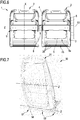
- the abutting portion 4 of the support body 2 has, in the outer face (or rear wall) 4b, a transversal groove 27 separating by a predetermined distance a service table 28 available to a passenger (the one, which, inside a vehicle such as a train, is seated on the seat behind the one to which the bearing structure 1 is installed in this description, which is conventionally considered as a reference) from a transversal bar 29 protruding from such outer face 4b of the abutting portion 4.
- the service table 28 is, as usual, rotatably coupled to the abutting portion 4 along an auxiliary longitudinal axis Z', in order to define:
- the transversal groove 27 and transversal bar 29 have an ergonomic rounded or convex profile which, together with the predetermined distance separating the lower edge 28b of the service table 28 from the transversal bar 29, offers greater safety conditions for the passenger (particularly in case of a kid) when the service table 28 is rotated about the auxiliary longitudinal axis Z', in order to prevent or alleviate the negative consequences caused by inadvertently possibly pinching the fingers of the passenger.
- the predetermined distance - representing the height of the transversal groove 27 - separates the service table 28 from the transversal bar 29 in anyone of said rest position and operative position of the service table 28.
- the bearing structure 1 of the invention comprises electric connecting means or wirings, generally indicated by reference 30, for electric outlets, also of the USB type, partially contained even though mainly inside the stiffening tubular element 18 of the reinforcement means 8 and adapted to be electrically connected to an electric power unit available on the considered vehicle, outside such tubular element 18, the electric connecting means 30 are suitably insulated and supported by an abutting plate 12 fixed to the inner wall of the vehicle by known type fixing means.
- Figure 7 shows a first embodiment variant of the invention, in which the bearing structure, herein generally indicated by reference 50, is distinguished from the beforehand one described in Figures from 1 to 7 and indicated by reference 1, first of all by comprising a single support body 51, preferably always of a monobloc type.
- the bearing structure 50 of the invention distinguishes itself from the bearing structure 1 of the invention because it comprises lighting means, generally indicated by reference 59 and, for example, of a low consumption type such as a light strip comprising a plurality of LEDs, coupled to the stiffening tubular element 58 of the reinforcement means 57 so that they face the floor of the vehicle or transporting means, toward which they emit the light when needed, being simultaneously mostly protected inside such tubular element 58.
- lighting means generally indicated by reference 59 and, for example, of a low consumption type such as a light strip comprising a plurality of LEDs, coupled to the stiffening tubular element 58 of the reinforcement means 57 so that they face the floor of the vehicle or transporting means, toward which they emit the light when needed, being simultaneously mostly protected inside such tubular element 58.
- the bearing structure 1 or 50 of the present invention is set up in the above beforehand defined constructive characteristics before being painted and customized according to the specific and unique requirements of a customer.
- the bearing structure 1 or 50 of the invention is therefore delivered to the company responsible for completing it by adding to the supporting body 2 or 51 the seating, backrest, armrests and other accessories which usually are part of a passenger seat for public and/or private transporting means in the interest of the operations to be implemented for performing an effective and efficient transport.
- only one of the two side edges, already folded, of the base portion and/or of the abutting portion of the support body could comprise, on at least one longitudinal section, an additional double fold mostly facing respective bottom central wall.
- the base portion of the support body could comprise at least one of the two side edges opposite to each other, folded in order to have a substantially U-shaped cross-section, for at least a longitudinal section, or this could happen not just for the base portion but also for the abutting portion of the support body, if not thereby departing from its scope as defined by the claims.
- the bearing structure of the invention could belong to passenger, driver and/or engineer seats, partially installed to the floor of the vehicle or of the transporting means by a single anchoring foot, or completely abutting on the floor of the transporting means by at least two anchoring feet suitably distanced from each other and applied below the support body or is cantileverly anchored by brackets only to the side wall of the considered transport system, typically a train.
Landscapes
- Engineering & Computer Science (AREA)
- Mechanical Engineering (AREA)
- Aviation & Aerospace Engineering (AREA)
- Transportation (AREA)
- Seats For Vehicles (AREA)
- Body Structure For Vehicles (AREA)
Claims (14)
- Trägerstruktur (1; 50) für Beifahrer- und/oder Fahrersitze von Fahrzeugen, umfassend:- wenigstens einen im Wesentlichen L-förmigen Stützkörper (2; 51), um einen Basisabschnitt (3) aufzunehmen, der dazu ausgelegt ist, das Sitzpolster eines Beifahrer- und/oder Fahrersitzes zu unterstützen, und einen nach oben herausstehenden angrenzenden Abschnitt bzw. Lehnenabschnitt (4), der dazu ausgelegt ist, die Rückenlehne des Beifahrer- und/oder Fahrersitzes zu unterstützen, wobei wenigstens einer aus dem Basisabschnitt (3) und dem angrenzenden Abschnitt (4) mit einem Paar von einander gegenüberliegenden gefalteten Seitenkanten (6, 7) versehen ist, die nach außen gerichtet gemäß einer Ebene vorstehen, welche im Wesentlichen senkrecht zu der Ebene ist, die durch eine untere Mittelwand (5) des Basisabschnitts (3) und/oder des angrenzenden Abschnitts (4) definiert ist, wobei ein Doppel-S-förmiger Falz an den gefalteten Seitenkanten (6, 7) ausgebildet ist, welcher einen abrupten Versatz definiert, um einen ersten Bereich der gefalteten Kante (6) zu definieren, wobei sich dieser parallel zu einer durch die jeweiligen Seitenkanten (6, 7) definierten Ebene erstreckt;- Verstärkungsmittel (8; 57), das quer mit dem Stützkörper (2; 51) gekoppelt ist, und zwar im Wesentlichen in der Nähe oder an einer Verbindungszone (9), die den Basisabschnitt (3) mit dem angrenzenden Abschnitt (4) verbindet, dadurch gekennzeichnet, dass der Basisabschnitt (3) und der angrenzende Abschnitt (4) das Verstärkungsmittel (8; 57) in einer entsprechenden Überlappungszone (14; 15) teilweise überlappen und wenigstens ein Längsabschnitt (6a, 7a) von wenigstens einer der Seitenkanten (6, 7) folgendes umfasst:- eine erste Hilfsbiegung bzw. zusätzliche Krümmung (10), welche eine im Wesentlichen orthogonale Ebene zu der durch jede der gefalteten Seitenkanten (6, 7) definierten Ebene definiert;- eine zweite Hilfsbiegung (11), anschließend an die erste Hilfsbiegung, die an deren freiem Ende (61a, 71a) von wenigstens einer der Seitenkanten (6, 7) angeordnet ist und eine Ebene definiert, die im Wesentlichen orthogonal zu der durch die erste Hilfsbiegung (10) definierten Ebene und im Wesentlichen parallel zu der durch jede der gefalteten Seitenkanten (6, 7) definierten Ebene ist,so dass wenigstens eine der Seitenkanten (6, 7) an wenigstens dem Längsabschnitt (6a, 7a) zu einem Profil gefaltet ist, das im Querschnitt eine Hakenform aufweist.
- Struktur (1; 50) gemäß Anspruch 1, dadurch gekennzeichnet, dass der Stützkörper (2; 51) aus einem Guss ist, erhalten durch Gesenkformen eines einzelnen Stückes Metallmaterial, so dass der Basisabschnitt (3) und der angrenzende Abschnitt (4) miteinander einen einzelnen Körper ausbilden.
- Struktur (1; 50) gemäß einem der vorangehenden Ansprüche, dadurch gekennzeichnet, dass das Verstärkungsmittel (8; 57) mit dem Stützkörper (2; 51) durch strukturelle Verbindungsmittel (16) verbunden sind.
- Struktur (1; 50) gemäß Anspruch 3, dadurch gekennzeichnet, dass das strukturelle Verbindungsmittel (16) irgendein strukturelles Fügungsmaterial umfasst, ausgewählt aus der Gruppe, bestehend aus Schweißmitteln, Klebstoffen und/oder ähnlichem.
- Struktur (1; 50) gemäß Anspruch 3, dadurch gekennzeichnet, dass das strukturelle Verbindungsmittel (16) eine Schweißnaht umfasst, die entlang der Überlappungszone (14, 15) und/oder der Außenfläche (2a) des Stützkörpers (2; 51) und eines Kopfabschnitts (17) des Verstärkungsmittels (8; 57) ausgeführt ist.
- Struktur (1; 50) gemäß einem der vorangehenden Ansprüche, dadurch gekennzeichnet, dass das Verstärkungsmittel (8; 57) ein rohrförmiges Versteifungselement (18; 58) umfasst, welches sich entlang einer Längsachse (Z) erstreckt, die sich im Wesentlichen senkrecht zu der Erstreckungsrichtung der Längsachse (X, Y) des Basisabschnitts und des angrenzenden Abschnitts (4) des Stützkörpers (2; 51) erstreckt.
- Struktur (1; 50) gemäß Anspruch 6, dadurch gekennzeichnet, dass das rohrförmige Versteifungselement (18; 58) mit dem Stützkörper (2; 51) derart verbunden ist, dass es in einer Verbindungsfläche (19) enthalten ist, die den Stützkörper (2; 51) in eine Höhe einbezieht, deren Maximalwert gleich dem Durchmesser des rohrförmigen Versteifungselements (18; 58) ist.
- Struktur (1; 50) gemäß Anspruch 6 oder 7, dadurch gekennzeichnet, dass das rohrförmige Versteifungselement (18; 58) teilweise aus der Außenfläche (3b, 4b) des Basisabschnitts (3) und/oder des angrenzenden Abschnitts (4), in welches es strukturell integriert ist, vorsteht, wobei das rohrförmige Versteifungselement passend und teilweise in einer Längsöffnung (20) mit offenem Profil in dem Stützkörper (2; 51) untergebracht ist.
- Struktur (1; 50) gemäß irgendeinem der vorangehenden Ansprüche, dadurch gekennzeichnet, dass die Verbindungszone (9), welche den Basisabschnitt (3) mit dem angrenzenden Abschnitt (4) des Stützkörpers (2; 51) verbindet, aus einem Guss mit dem Basisabschnitt (3) und dem angrenzenden Abschnitt (4) ausgebildet ist.
- Struktur (1; 50) gemäß irgendeinem der vorangehenden Ansprüche, dadurch gekennzeichnet, dass die wenigstens eine gefaltete Seitenkante (6, 7) des Basisabschnitts (3) und/oder des angrenzenden Abschnitts (4) ein erstes Versteifungsmittel (23) umfasst, das ausgelegt ist, die strukturelle Steifheit des Stützkörpers (2; 51) zu erhöhen.
- Struktur (1; 50) gemäß irgendeinem der vorangehenden Ansprüche, dadurch gekennzeichnet, dass die untere Mittelwand (5) des Basisabschnitts (3) und/oder des angrenzenden Abschnitts (4) ein zweites Versteifungsmittel (25) umfasst, das ausgelegt ist, die strukturelle Steifheit des Stützkörpers (2; 51) zu erhöhen.
- Struktur (1; 50) gemäß Anspruch 11, dadurch gekennzeichnet, dass das zweite Versteifungsmittel (25) mehrere Längsrippen umfasst, die aus der oberen Fläche (5a) der unteren Mittelwand (5) des Basisabschnitts (3) und/oder des angrenzenden Abschnitts (4) hervorstehen.
- Struktur (1; 50) gemäß irgendeinem der vorangehenden Ansprüche, dadurch gekennzeichnet, dass der angrenzende Abschnitt (4) des Stützkörpers (2; 51) in der Außenfläche (4b) eine Querfurche (27) aufweist, die einen Abstelltisch für einen Mitfahrer mittels eines vorbestimmten Abstands von einer von der Außenfläche (4b) des angrenzenden Abschnitts (4) hervorstehenden Querstange beabstandet, wobei der Abstelltisch (28) drehbar mit dem angrenzenden Abschnitt (4) verbunden ist, um dadurch zu definieren:• eine Ruheposition, in welcher die Oberseite des Abstelltisches (28) nahe der äußeren Fläche (4b) des angrenzenden Abschnitts (4) angeordnet ist und der Abstelltisch (28) im Wesentlichen gänzlich in dem angrenzenden Abschnitt (4) des Stützkörpers (2; 51) enthalten ist;• eine Arbeitslage, in welcher die Oberseite des Abstelltisches (28) nach oben schaut und der Abstelltisch (28) in einer Ebene hervorragt, welche die äußere Fläche (4b) des angrenzenden Abschnitts (4) des Stützkörpers (2; 51) kreuzt, um dem Mitfahrer so für das Ablegen von Objekten verfügbar zu sein.
- Struktur (1; 50) gemäß Anspruch 14, dadurch gekennzeichnet, dass die Querfurche (27) und die Querstange (29) ein rundliches oder ein gewölbtes bzw. konvexes Profil aufweisen.
Priority Applications (1)
| Application Number | Priority Date | Filing Date | Title |
|---|---|---|---|
| PL18167941T PL3461684T3 (pl) | 2017-04-20 | 2018-04-18 | Konstrukcja nośna siedzeń pasażerów dla pojazdów |
Applications Claiming Priority (1)
| Application Number | Priority Date | Filing Date | Title |
|---|---|---|---|
| IT102017000043293A IT201700043293A1 (it) | 2017-04-20 | 2017-04-20 | Struttura portante di sedili passeggeri per veicoli |
Publications (2)
| Publication Number | Publication Date |
|---|---|
| EP3461684A1 EP3461684A1 (de) | 2019-04-03 |
| EP3461684B1 true EP3461684B1 (de) | 2021-06-23 |
Family
ID=59700128
Family Applications (1)
| Application Number | Title | Priority Date | Filing Date |
|---|---|---|---|
| EP18167941.6A Active EP3461684B1 (de) | 2017-04-20 | 2018-04-18 | Tragende struktur für fahrzeugsitze |
Country Status (3)
| Country | Link |
|---|---|
| EP (1) | EP3461684B1 (de) |
| IT (1) | IT201700043293A1 (de) |
| PL (1) | PL3461684T3 (de) |
Cited By (1)
| Publication number | Priority date | Publication date | Assignee | Title |
|---|---|---|---|---|
| EP4497651A1 (de) * | 2023-07-24 | 2025-01-29 | ALSTOM Holdings | Freitragende sitzstruktur |
Families Citing this family (1)
| Publication number | Priority date | Publication date | Assignee | Title |
|---|---|---|---|---|
| FR3121112B1 (fr) * | 2021-03-23 | 2023-03-10 | SNCF Voyageurs | Assemblage de siège pour véhicule ferroviaire à fixation rapide |
Family Cites Families (8)
| Publication number | Priority date | Publication date | Assignee | Title |
|---|---|---|---|---|
| GB1149323A (en) * | 1967-04-26 | 1969-04-23 | Coventry Hood & Sidescreen Com | Frame for a bucket-type vehicle seat |
| FR2515946B1 (fr) * | 1981-11-11 | 1985-10-11 | Keiper Automobiltechnik Gmbh | Cadre de dossier pour sieges, notamment pour sieges de vehicules automobiles |
| US5464273A (en) * | 1991-07-15 | 1995-11-07 | Kotobuki Seating Co. Ltd. | Seat construction |
| US5338100A (en) * | 1992-02-24 | 1994-08-16 | Itt Corporation | High strength automotive seat frame and method |
| US5499863A (en) * | 1993-05-17 | 1996-03-19 | Toyota Shatai Kabushiki Kaisha | Seat back frame |
| FR2801254A1 (fr) | 1999-11-22 | 2001-05-25 | Lohr Ind | Siege suspendu a fixation laterale sur un montant de structure pour vehicule de transport |
| US6550861B1 (en) * | 2001-11-21 | 2003-04-22 | B E Aerospace, Inc. | Passenger seat meal tray |
| GB0903907D0 (en) | 2009-03-06 | 2009-04-22 | Robinson Dominic J | Seat assembly |
-
2017
- 2017-04-20 IT IT102017000043293A patent/IT201700043293A1/it unknown
-
2018
- 2018-04-18 EP EP18167941.6A patent/EP3461684B1/de active Active
- 2018-04-18 PL PL18167941T patent/PL3461684T3/pl unknown
Cited By (1)
| Publication number | Priority date | Publication date | Assignee | Title |
|---|---|---|---|---|
| EP4497651A1 (de) * | 2023-07-24 | 2025-01-29 | ALSTOM Holdings | Freitragende sitzstruktur |
Also Published As
| Publication number | Publication date |
|---|---|
| EP3461684A1 (de) | 2019-04-03 |
| PL3461684T3 (pl) | 2022-01-24 |
| IT201700043293A1 (it) | 2018-10-20 |
Similar Documents
| Publication | Publication Date | Title |
|---|---|---|
| US12077078B2 (en) | Seat frame | |
| EP3461684B1 (de) | Tragende struktur für fahrzeugsitze | |
| US8870293B2 (en) | One-piece seat back frame assembly and method of making same | |
| US10005349B2 (en) | Structural underbody support in a vehicle | |
| US4036527A (en) | Transportation seating construction and system | |
| US20170326954A1 (en) | Reinforced vehicle door against side impact | |
| CN105142987B (zh) | 机动车辆用保险杠 | |
| US11273873B2 (en) | Fender flare | |
| US20140054929A1 (en) | 2-door/3-door type vehicle having reinforcement member against side impact | |
| US8262131B2 (en) | Automotive knee bolster system | |
| US20090184562A1 (en) | School bus seat frame back attachment | |
| US8474870B1 (en) | Vehicle frame assembly | |
| CN103465814A (zh) | 三点式安全带座椅骨架结构 | |
| CN205589020U (zh) | 一种汽车二排座椅安装结构 | |
| WO2012024622A1 (en) | One piece rear back | |
| CN106029497B (zh) | 飞机座椅安装装置 | |
| US20090184561A1 (en) | Variable length reinforcement to control seat back performance | |
| EP3192724B1 (de) | Struktur für eine motorfahrzeugkarosserie | |
| EP3544861B1 (de) | Leichtgewichtige stossfängerstange | |
| WO2011127289A1 (en) | Seat back with integrated head restraint | |
| CN207579977U (zh) | 皮卡车防滚架与皮卡车 | |
| ITMO20100112A1 (it) | Sistema per la fabbricazione e l'assemblaggio di strutture a scaffale, in particolare per l'allestimento interno di furgoni commerciali attrezzati | |
| US20150175045A1 (en) | Motor vehicle seat element | |
| CN104828162B (zh) | 汽车后备胎装置 | |
| JP7000168B2 (ja) | 車両用衝突安全装置 |
Legal Events
| Date | Code | Title | Description |
|---|---|---|---|
| PUAI | Public reference made under article 153(3) epc to a published international application that has entered the european phase |
Free format text: ORIGINAL CODE: 0009012 |
|
| STAA | Information on the status of an ep patent application or granted ep patent |
Free format text: STATUS: THE APPLICATION HAS BEEN PUBLISHED |
|
| AK | Designated contracting states |
Kind code of ref document: A1 Designated state(s): AL AT BE BG CH CY CZ DE DK EE ES FI FR GB GR HR HU IE IS IT LI LT LU LV MC MK MT NL NO PL PT RO RS SE SI SK SM TR |
|
| AX | Request for extension of the european patent |
Extension state: BA ME |
|
| STAA | Information on the status of an ep patent application or granted ep patent |
Free format text: STATUS: REQUEST FOR EXAMINATION WAS MADE |
|
| 17P | Request for examination filed |
Effective date: 20191003 |
|
| RBV | Designated contracting states (corrected) |
Designated state(s): AL AT BE BG CH CY CZ DE DK EE ES FI FR GB GR HR HU IE IS IT LI LT LU LV MC MK MT NL NO PL PT RO RS SE SI SK SM TR |
|
| REG | Reference to a national code |
Ref country code: DE Ref legal event code: R079 Ref document number: 602018018859 Country of ref document: DE Free format text: PREVIOUS MAIN CLASS: B60N0002680000 Ipc: B60N0002010000 |
|
| GRAP | Despatch of communication of intention to grant a patent |
Free format text: ORIGINAL CODE: EPIDOSNIGR1 |
|
| STAA | Information on the status of an ep patent application or granted ep patent |
Free format text: STATUS: GRANT OF PATENT IS INTENDED |
|
| RIC1 | Information provided on ipc code assigned before grant |
Ipc: B60N 2/01 20060101AFI20210126BHEP Ipc: B60N 2/015 20060101ALI20210126BHEP Ipc: B60N 2/68 20060101ALI20210126BHEP Ipc: B60N 2/24 20060101ALI20210126BHEP Ipc: B61D 33/00 20060101ALI20210126BHEP |
|
| INTG | Intention to grant announced |
Effective date: 20210303 |
|
| GRAS | Grant fee paid |
Free format text: ORIGINAL CODE: EPIDOSNIGR3 |
|
| GRAA | (expected) grant |
Free format text: ORIGINAL CODE: 0009210 |
|
| STAA | Information on the status of an ep patent application or granted ep patent |
Free format text: STATUS: THE PATENT HAS BEEN GRANTED |
|
| AK | Designated contracting states |
Kind code of ref document: B1 Designated state(s): AL AT BE BG CH CY CZ DE DK EE ES FI FR GB GR HR HU IE IS IT LI LT LU LV MC MK MT NL NO PL PT RO RS SE SI SK SM TR |
|
| REG | Reference to a national code |
Ref country code: GB Ref legal event code: FG4D |
|
| REG | Reference to a national code |
Ref country code: CH Ref legal event code: EP |
|
| REG | Reference to a national code |
Ref country code: DE Ref legal event code: R096 Ref document number: 602018018859 Country of ref document: DE Ref country code: AT Ref legal event code: REF Ref document number: 1404040 Country of ref document: AT Kind code of ref document: T Effective date: 20210715 |
|
| REG | Reference to a national code |
Ref country code: IE Ref legal event code: FG4D |
|
| REG | Reference to a national code |
Ref country code: LT Ref legal event code: MG9D |
|
| PG25 | Lapsed in a contracting state [announced via postgrant information from national office to epo] |
Ref country code: BG Free format text: LAPSE BECAUSE OF FAILURE TO SUBMIT A TRANSLATION OF THE DESCRIPTION OR TO PAY THE FEE WITHIN THE PRESCRIBED TIME-LIMIT Effective date: 20210923 Ref country code: HR Free format text: LAPSE BECAUSE OF FAILURE TO SUBMIT A TRANSLATION OF THE DESCRIPTION OR TO PAY THE FEE WITHIN THE PRESCRIBED TIME-LIMIT Effective date: 20210623 Ref country code: LT Free format text: LAPSE BECAUSE OF FAILURE TO SUBMIT A TRANSLATION OF THE DESCRIPTION OR TO PAY THE FEE WITHIN THE PRESCRIBED TIME-LIMIT Effective date: 20210623 Ref country code: FI Free format text: LAPSE BECAUSE OF FAILURE TO SUBMIT A TRANSLATION OF THE DESCRIPTION OR TO PAY THE FEE WITHIN THE PRESCRIBED TIME-LIMIT Effective date: 20210623 |
|
| REG | Reference to a national code |
Ref country code: AT Ref legal event code: MK05 Ref document number: 1404040 Country of ref document: AT Kind code of ref document: T Effective date: 20210623 |
|
| PG25 | Lapsed in a contracting state [announced via postgrant information from national office to epo] |
Ref country code: GR Free format text: LAPSE BECAUSE OF FAILURE TO SUBMIT A TRANSLATION OF THE DESCRIPTION OR TO PAY THE FEE WITHIN THE PRESCRIBED TIME-LIMIT Effective date: 20210924 Ref country code: RS Free format text: LAPSE BECAUSE OF FAILURE TO SUBMIT A TRANSLATION OF THE DESCRIPTION OR TO PAY THE FEE WITHIN THE PRESCRIBED TIME-LIMIT Effective date: 20210623 Ref country code: SE Free format text: LAPSE BECAUSE OF FAILURE TO SUBMIT A TRANSLATION OF THE DESCRIPTION OR TO PAY THE FEE WITHIN THE PRESCRIBED TIME-LIMIT Effective date: 20210623 Ref country code: LV Free format text: LAPSE BECAUSE OF FAILURE TO SUBMIT A TRANSLATION OF THE DESCRIPTION OR TO PAY THE FEE WITHIN THE PRESCRIBED TIME-LIMIT Effective date: 20210623 Ref country code: NO Free format text: LAPSE BECAUSE OF FAILURE TO SUBMIT A TRANSLATION OF THE DESCRIPTION OR TO PAY THE FEE WITHIN THE PRESCRIBED TIME-LIMIT Effective date: 20210923 |
|
| REG | Reference to a national code |
Ref country code: NL Ref legal event code: MP Effective date: 20210623 |
|
| PG25 | Lapsed in a contracting state [announced via postgrant information from national office to epo] |
Ref country code: AT Free format text: LAPSE BECAUSE OF FAILURE TO SUBMIT A TRANSLATION OF THE DESCRIPTION OR TO PAY THE FEE WITHIN THE PRESCRIBED TIME-LIMIT Effective date: 20210623 Ref country code: CZ Free format text: LAPSE BECAUSE OF FAILURE TO SUBMIT A TRANSLATION OF THE DESCRIPTION OR TO PAY THE FEE WITHIN THE PRESCRIBED TIME-LIMIT Effective date: 20210623 Ref country code: PT Free format text: LAPSE BECAUSE OF FAILURE TO SUBMIT A TRANSLATION OF THE DESCRIPTION OR TO PAY THE FEE WITHIN THE PRESCRIBED TIME-LIMIT Effective date: 20211025 Ref country code: NL Free format text: LAPSE BECAUSE OF FAILURE TO SUBMIT A TRANSLATION OF THE DESCRIPTION OR TO PAY THE FEE WITHIN THE PRESCRIBED TIME-LIMIT Effective date: 20210623 Ref country code: RO Free format text: LAPSE BECAUSE OF FAILURE TO SUBMIT A TRANSLATION OF THE DESCRIPTION OR TO PAY THE FEE WITHIN THE PRESCRIBED TIME-LIMIT Effective date: 20210623 Ref country code: ES Free format text: LAPSE BECAUSE OF FAILURE TO SUBMIT A TRANSLATION OF THE DESCRIPTION OR TO PAY THE FEE WITHIN THE PRESCRIBED TIME-LIMIT Effective date: 20210623 Ref country code: EE Free format text: LAPSE BECAUSE OF FAILURE TO SUBMIT A TRANSLATION OF THE DESCRIPTION OR TO PAY THE FEE WITHIN THE PRESCRIBED TIME-LIMIT Effective date: 20210623 Ref country code: SM Free format text: LAPSE BECAUSE OF FAILURE TO SUBMIT A TRANSLATION OF THE DESCRIPTION OR TO PAY THE FEE WITHIN THE PRESCRIBED TIME-LIMIT Effective date: 20210623 Ref country code: SK Free format text: LAPSE BECAUSE OF FAILURE TO SUBMIT A TRANSLATION OF THE DESCRIPTION OR TO PAY THE FEE WITHIN THE PRESCRIBED TIME-LIMIT Effective date: 20210623 |
|
| REG | Reference to a national code |
Ref country code: DE Ref legal event code: R097 Ref document number: 602018018859 Country of ref document: DE |
|
| PG25 | Lapsed in a contracting state [announced via postgrant information from national office to epo] |
Ref country code: DK Free format text: LAPSE BECAUSE OF FAILURE TO SUBMIT A TRANSLATION OF THE DESCRIPTION OR TO PAY THE FEE WITHIN THE PRESCRIBED TIME-LIMIT Effective date: 20210623 |
|
| PLBE | No opposition filed within time limit |
Free format text: ORIGINAL CODE: 0009261 |
|
| STAA | Information on the status of an ep patent application or granted ep patent |
Free format text: STATUS: NO OPPOSITION FILED WITHIN TIME LIMIT |
|
| 26N | No opposition filed |
Effective date: 20220324 |
|
| PG25 | Lapsed in a contracting state [announced via postgrant information from national office to epo] |
Ref country code: AL Free format text: LAPSE BECAUSE OF FAILURE TO SUBMIT A TRANSLATION OF THE DESCRIPTION OR TO PAY THE FEE WITHIN THE PRESCRIBED TIME-LIMIT Effective date: 20210623 |
|
| REG | Reference to a national code |
Ref country code: BE Ref legal event code: MM Effective date: 20220430 |
|
| PG25 | Lapsed in a contracting state [announced via postgrant information from national office to epo] |
Ref country code: MC Free format text: LAPSE BECAUSE OF FAILURE TO SUBMIT A TRANSLATION OF THE DESCRIPTION OR TO PAY THE FEE WITHIN THE PRESCRIBED TIME-LIMIT Effective date: 20210623 Ref country code: LU Free format text: LAPSE BECAUSE OF NON-PAYMENT OF DUE FEES Effective date: 20220418 |
|
| PG25 | Lapsed in a contracting state [announced via postgrant information from national office to epo] |
Ref country code: BE Free format text: LAPSE BECAUSE OF NON-PAYMENT OF DUE FEES Effective date: 20220430 |
|
| PG25 | Lapsed in a contracting state [announced via postgrant information from national office to epo] |
Ref country code: HU Free format text: LAPSE BECAUSE OF FAILURE TO SUBMIT A TRANSLATION OF THE DESCRIPTION OR TO PAY THE FEE WITHIN THE PRESCRIBED TIME-LIMIT; INVALID AB INITIO Effective date: 20180418 |
|
| PG25 | Lapsed in a contracting state [announced via postgrant information from national office to epo] |
Ref country code: MK Free format text: LAPSE BECAUSE OF FAILURE TO SUBMIT A TRANSLATION OF THE DESCRIPTION OR TO PAY THE FEE WITHIN THE PRESCRIBED TIME-LIMIT Effective date: 20210623 Ref country code: CY Free format text: LAPSE BECAUSE OF FAILURE TO SUBMIT A TRANSLATION OF THE DESCRIPTION OR TO PAY THE FEE WITHIN THE PRESCRIBED TIME-LIMIT Effective date: 20210623 |
|
| PG25 | Lapsed in a contracting state [announced via postgrant information from national office to epo] |
Ref country code: MT Free format text: LAPSE BECAUSE OF FAILURE TO SUBMIT A TRANSLATION OF THE DESCRIPTION OR TO PAY THE FEE WITHIN THE PRESCRIBED TIME-LIMIT Effective date: 20210623 |
|
| PGFP | Annual fee paid to national office [announced via postgrant information from national office to epo] |
Ref country code: IT Payment date: 20250130 Year of fee payment: 8 |
|
| PGFP | Annual fee paid to national office [announced via postgrant information from national office to epo] |
Ref country code: PL Payment date: 20250408 Year of fee payment: 8 Ref country code: DE Payment date: 20250410 Year of fee payment: 8 |
|
| PGFP | Annual fee paid to national office [announced via postgrant information from national office to epo] |
Ref country code: GB Payment date: 20250411 Year of fee payment: 8 |
|
| PGFP | Annual fee paid to national office [announced via postgrant information from national office to epo] |
Ref country code: FR Payment date: 20250410 Year of fee payment: 8 |
|
| PGFP | Annual fee paid to national office [announced via postgrant information from national office to epo] |
Ref country code: CH Payment date: 20250501 Year of fee payment: 8 |
|
| PGFP | Annual fee paid to national office [announced via postgrant information from national office to epo] |
Ref country code: IE Payment date: 20250409 Year of fee payment: 8 |
|
| PG25 | Lapsed in a contracting state [announced via postgrant information from national office to epo] |
Ref country code: TR Free format text: LAPSE BECAUSE OF FAILURE TO SUBMIT A TRANSLATION OF THE DESCRIPTION OR TO PAY THE FEE WITHIN THE PRESCRIBED TIME-LIMIT Effective date: 20210623 |