EP3461599B1 - Robot - Google Patents
Robot Download PDFInfo
- Publication number
- EP3461599B1 EP3461599B1 EP18197157.3A EP18197157A EP3461599B1 EP 3461599 B1 EP3461599 B1 EP 3461599B1 EP 18197157 A EP18197157 A EP 18197157A EP 3461599 B1 EP3461599 B1 EP 3461599B1
- Authority
- EP
- European Patent Office
- Prior art keywords
- arm
- robot
- motor
- base
- driving
- Prior art date
- Legal status (The legal status is an assumption and is not a legal conclusion. Google has not performed a legal analysis and makes no representation as to the accuracy of the status listed.)
- Active
Links
- 230000009467 reduction Effects 0.000 description 43
- 239000000758 substrate Substances 0.000 description 43
- 239000012636 effector Substances 0.000 description 17
- 230000036544 posture Effects 0.000 description 17
- 238000001514 detection method Methods 0.000 description 8
- 238000000034 method Methods 0.000 description 8
- 230000006870 function Effects 0.000 description 5
- 238000010586 diagram Methods 0.000 description 4
- 230000003028 elevating effect Effects 0.000 description 4
- 238000012423 maintenance Methods 0.000 description 4
- 238000004590 computer program Methods 0.000 description 3
- 238000001816 cooling Methods 0.000 description 3
- 239000000463 material Substances 0.000 description 3
- 238000011144 upstream manufacturing Methods 0.000 description 3
- 238000009413 insulation Methods 0.000 description 2
- 230000007246 mechanism Effects 0.000 description 2
- 238000007789 sealing Methods 0.000 description 2
- 238000009423 ventilation Methods 0.000 description 2
- 229910000838 Al alloy Inorganic materials 0.000 description 1
- 230000009471 action Effects 0.000 description 1
- 229910045601 alloy Inorganic materials 0.000 description 1
- 239000000956 alloy Substances 0.000 description 1
- 229910052782 aluminium Inorganic materials 0.000 description 1
- XAGFODPZIPBFFR-UHFFFAOYSA-N aluminium Chemical compound [Al] XAGFODPZIPBFFR-UHFFFAOYSA-N 0.000 description 1
- 238000005452 bending Methods 0.000 description 1
- 230000008901 benefit Effects 0.000 description 1
- 230000008859 change Effects 0.000 description 1
- 239000000470 constituent Substances 0.000 description 1
- 230000001419 dependent effect Effects 0.000 description 1
- 239000000428 dust Substances 0.000 description 1
- 238000007689 inspection Methods 0.000 description 1
- 238000004519 manufacturing process Methods 0.000 description 1
- 239000007769 metal material Substances 0.000 description 1
- 239000000700 radioactive tracer Substances 0.000 description 1
- 210000000707 wrist Anatomy 0.000 description 1
Images


Classifications
-
- B—PERFORMING OPERATIONS; TRANSPORTING
- B25—HAND TOOLS; PORTABLE POWER-DRIVEN TOOLS; MANIPULATORS
- B25J—MANIPULATORS; CHAMBERS PROVIDED WITH MANIPULATION DEVICES
- B25J9/00—Programme-controlled manipulators
- B25J9/06—Programme-controlled manipulators characterised by multi-articulated arms
-
- B—PERFORMING OPERATIONS; TRANSPORTING
- B25—HAND TOOLS; PORTABLE POWER-DRIVEN TOOLS; MANIPULATORS
- B25J—MANIPULATORS; CHAMBERS PROVIDED WITH MANIPULATION DEVICES
- B25J18/00—Arms
-
- B—PERFORMING OPERATIONS; TRANSPORTING
- B25—HAND TOOLS; PORTABLE POWER-DRIVEN TOOLS; MANIPULATORS
- B25J—MANIPULATORS; CHAMBERS PROVIDED WITH MANIPULATION DEVICES
- B25J19/00—Accessories fitted to manipulators, e.g. for monitoring, for viewing; Safety devices combined with or specially adapted for use in connection with manipulators
- B25J19/0054—Cooling means
-
- B—PERFORMING OPERATIONS; TRANSPORTING
- B25—HAND TOOLS; PORTABLE POWER-DRIVEN TOOLS; MANIPULATORS
- B25J—MANIPULATORS; CHAMBERS PROVIDED WITH MANIPULATION DEVICES
- B25J9/00—Programme-controlled manipulators
- B25J9/0009—Constructional details, e.g. manipulator supports, bases
-
- B—PERFORMING OPERATIONS; TRANSPORTING
- B25—HAND TOOLS; PORTABLE POWER-DRIVEN TOOLS; MANIPULATORS
- B25J—MANIPULATORS; CHAMBERS PROVIDED WITH MANIPULATION DEVICES
- B25J9/00—Programme-controlled manipulators
- B25J9/10—Programme-controlled manipulators characterised by positioning means for manipulator elements
- B25J9/104—Programme-controlled manipulators characterised by positioning means for manipulator elements with cables, chains or ribbons
-
- B—PERFORMING OPERATIONS; TRANSPORTING
- B25—HAND TOOLS; PORTABLE POWER-DRIVEN TOOLS; MANIPULATORS
- B25J—MANIPULATORS; CHAMBERS PROVIDED WITH MANIPULATION DEVICES
- B25J9/00—Programme-controlled manipulators
- B25J9/10—Programme-controlled manipulators characterised by positioning means for manipulator elements
- B25J9/12—Programme-controlled manipulators characterised by positioning means for manipulator elements electric
Definitions
- the present invention relates to a robot.
- a robot including a base and a robot arm including a plurality of arms (links) .
- One arm of adjacent two arms of the robot arm is rotatably coupled to the other arm via a joint section.
- An arm on the most distal end side (the most upstream side) is rotatably coupled to the base via a joint section.
- the joint sections are driven by motors.
- the arms rotate according to the driving of the joint sections.
- a hand is detachably attached to an arm on the most distal end side (the most downstream side) as an end effector.
- the robot grasps an object with the hand, moves the object to a predetermined place, and performs predetermined work such as assembly.
- JP 2011 177845 A discloses a SCARA robot.
- the robot and a robot controller including a control board for controlling driving of the robot are configured as separate bodies.
- JP 2014 240099 A discloses a robot which is excellent in accuracy of work and excellent in reliability of action.
- a robot includes a robot body which contains a body, an elevating part (connection part) connected to the body, a pair of articulated arms connected rotatably to the body, a base (stage) equipped with a support part for supporting the elevating part, an exterior for covering the support part, and a ventilation hole which allows ventilation between outside and inside of the exterior, and an elevating mechanism (moving mechanism) which moves the body in such a manner as it approach or separates from the base. It also includes a robot control device (electric circuit part) for controlling operation of the robot body.
- the base includes a hollow part (housing part) capable of housing a part of the elevating part when the body is lowered to approach the base, inside the exterior, and the robot control device is provided between the exterior and the hollow part.
- JP 2014 240099 A does not disclose a tabular section formed in a tabular shape and provided inside of the base of a robot, wherein a control board is attached to one surface of the tabular section, and a power supply section is attached to the other surface of the tabular section.
- An advantage of some aspects of the invention is to solve at least a part of the problems described above, and the invention can be implemented as the following forms or application examples.
- a robot according to the present invention is defined by claim 1.
- the first motor is provided in the first arm rather than on the inside of the base, maintenance and the like of the first motor can be easily and quickly performed. Compared with when the first motor, which is a heat source, is provided on the inside of the base, the temperature on the inside of the base can be reduced. Consequently, influence by the heat of the control board can be reduced.
- the robot further includes a first driving board configured to drive the first motor on the basis of a command of the control board, and the first driving board is provided in the first arm.
- the temperature on the inside of the base can be reduced. Accordingly, the influence by the heat of the control board can be reduced.
- a voltage supplied to the first motor is 1 V or more and 100 V or less.
- the first motor and the power supply board can be reduced in size. Accordingly, a reduction in the size of the robot can be achieved.
- the robot further includes a belt configured to transmit a driving force of the first motor.
- the first motor can be disposed in a position separated from a joint that couples the base and the first arm. Accordingly, the first motor can be disposed in a desired position of the first arm.
- the first motor does not overlap the first rotating axis when viewed from an axial direction of the first rotating axis.
- the robot arm includes a second arm provided on the first arm rotatably around a second rotating axis, and a second motor configured to rotate the second arm is provided in the second arm.
- the first motor and the second motor which are heat sources, are distributed to the first arm and the second arm. Compared with when the first motor and the second motor are not distributed, the temperatures of the first arm and the second arm can be reduced.
- the robot further includes a second driving board configured to drive the second motor on the basis of a command of the control board, and the second driving board is provided in the second arm.
- the first driving board and the second driving board which are heat sources, are distributed to the first arm and the second arm. Compared with when the first driving board and the second driving board are not distributed, the temperatures of the first arm and the second arm can be reduced.
- a fan is not provided on the base.
- the configuration of the base can be simplified.
- the base can be reduced in size. Accordingly, a reduction in the size of the robot can be achieved.
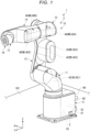
- Fig. 1 is a perspective view showing a robot according to an embodiment of the invention.
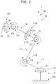
- Fig. 2 is a schematic diagram of the robot shown in Fig. 1 .
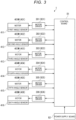
- Fig. 3 is a block diagram showing a main part of the robot shown in Fig. 1 .
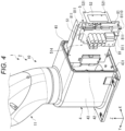
- Fig. 4 is a perspective view showing a base and a first arm of the robot shown in Fig. 1 .
- Fig. 5 is a perspective view showing the base of the robot shown in Fig. 1 .
- Fig. 6 is a perspective view showing the base of the robot shown in Fig. 1 .
- Fig. 7 is a perspective view showing the base of the robot shown in Fig. 1 .
- Fig. 8 is a perspective view showing the base and the first arm of the robot shown in Fig. 1 .
- Fig. 9 is a sectional view showing the base of the robot shown in Fig. 1 .
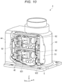
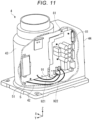
- Fig. 10 is a cutaway view obtained by cutting away a part of the base of the robot shown in Fig. 1 .
- Fig. 11 is a cutaway view obtained by cutting away a part of the base of the robot shown in Fig. 1 .
- Fig. 12 is a cutaway view obtained by cutting away a part of the base and the first arm of the robot shown in Fig. 1 .
- Fig. 13 is a perspective view showing the base of the robot shown in Fig. 1 . Note that, in Fig. 3 , one of two control boards is representatively illustrated and one of two power supply boards is representatively illustrated.
- the upper side in Figs. 1 and 2 is referred to "upper” or “upward” and the lower side in Figs. 1 and 2 is referred to as “lower” or “downward”.
- the base side in Figs. 1 and 2 is referred to as “proximal end” or “upstream” and the opposite side of the base side is referred to as “distal end” or “downstream”.
- the up-down direction in Figs. 1 and 2 is the vertical direction.
- Fig. 1 As shown in Fig. 1 , as three axes orthogonal to one another, an X axis, a Y axis, and a Z axis are shown.
- the distal end side of arrows indicating the axes is referred to as “+ (positive)” and the proximal end side of the arrows is referred to as “- (negative) ".
- the Z-axis direction is referred to as "vertical direction”.
- An X-Y plane including the X axis and the Y axis is referred to as "horizontal plane”.
- a direction in the X-Y plane (a direction along the X-Y plane) is referred to as "horizontal direction”.
- a direction parallel to the X axis is referred to as "X direction (X-axis direction)" as well.
- a direction parallel to the Y axis is referred to as “Y direction (Y-axis direction”) as well.
- a direction parallel to the Z axis is referred to as “Z direction (Z-axis direction)” as well.
- horizontal is not limited to complete horizontality and includes inclination at an angle of ⁇ 5° or less with respect to the horizontality.
- vertical is not limited to complete verticality and includes inclination at an angle of ⁇ 5° or less with respect to the verticality.
- parallel is not limited to complete parallelism of two lines (including axes) or surfaces and includes inclination at an angle of ⁇ 5° or less of the two lines or surfaces.
- orthogonality is not limited to complete orthogonality of two lines (including axes) or surfaces and includes inclination at an angle of ⁇ 5° or less of the two lines or surfaces.
- a robot 1 shown in Fig. 1 can be used in kinds of work such as conveyance, assembly, and inspection of various kinds of work (objects).
- the robot 1 includes a robot body 2 including a base 4 and a robot arm 10 displaceably coupled to (provided on) the base 4, a first driving source 401, a second driving source 402, a third driving source 403, a fourth driving source 404, a fifth driving source 405, and a sixth driving source 406, a control board 81, a power supply board 82, and driving boards 831, 832, 833, 834, 835, and 836.
- the robot arm 10 includes a first arm 11, a second arm 12, a third arm 13, a fourth arm 14, a fifth arm 15, and a sixth arm 16.
- a wrist is configured by the fifth arm 15 and the sixth arm 16.
- An end effector such as a hand can be detachably attached (connected) to the distal end of the sixth arm 16.
- An object (not shown in Figs. 1 to 3 ) can be grasped (held) by the end effector.
- the object grasped (held) by the end effector is not particularly limited. Examples of the object include various objects such as an electronic component and an electronic device.
- the end effector is not particularly limited if the end effector is capable of holding the object.
- Examples of the end effector include a hand capable of grasping (grabbing) the object and a suction head (a suction hand) that sucks to hold the object.
- a not-shown force detecting section may be provided between the sixth arm 16 and the end effector.
- the force detecting section detects a force (including a translational force and a moment) applied to the end effector.
- the force detecting section is not particularly limited.
- a six-axis force sensor capable of detecting force components (translational force components) in the respective axial directions of three axes orthogonal to one another and force components (rotational force components) around the respective three axes is used.
- the robot 1 is a single-arm six-axis vertical articulated robot in which the base 4, the first arm 11, the second arm 12, the third arm 13, the fourth arm 14, the fifth arm 15, and the sixth arm 16 are coupled in this order from the proximal end side toward the distal end side.
- the first arm 11, the second arm 12, the third arm 13, the fourth arm 14, the fifth arm 15, and the sixth arm 16 are respectively referred to as "arms" as well.
- the first driving source 401, the second driving source 402, the third driving source 403, the fourth driving source 404, the fifth driving source 405, and the sixth driving source 406 are respectively referred to as "driving sources” as well.
- the lengths of the arms 11 to 16 are not respectively particularly limited and can be set as appropriate.
- the base 4 and the first arm 11 are coupled via a joint 171.
- the first arm 11 has a first rotating axis O1 parallel to the vertical direction as a rotating center and is rotatable with respect to the base 4 around the first rotating axis O1.
- the first rotating axis O1 coincides with the normal of the upper surface of a floor 101, which is a setting surface of the base 4.
- the first rotating axis O1 is a rotating axis present on the most upstream side of the robot 1.
- the first arm 11 rotates according to driving of the first driving source 401 including a motor (a first motor) 401M and a reduction gear 6 (see Fig. 8 ).
- the motor 401M is controlled by the control board 81 via a motor driver 301 (a first motor driver) of the driving board 831 (a first driving board). Note that the reduction gear 6 may be omitted.
- the first arm 11 and the second arm 12 are coupled via a joint 172.
- the second arm 12 has a second rotating axis O2 parallel to the horizontal direction as a rotating center and is rotatable with respect to the first arm 11 around the second rotating axis 02.
- the second arm 12 is cantilevered at the distal end portion of the first arm 11. Consequently, it is possible to achieve a reduction in the size and the weight of the robot 1.
- the second rotating axis O2 is parallel to an axis orthogonal to the first rotating axis O1.
- the second arm 12 rotates according to driving of the second driving source 402 including a motor (a second motor) 402M and a reduction gear (not shown in Figs. 1 to 3 ).
- the motor 402M is controlled by the control board 81 via a motor driver 302 (a second motor driver) of the driving board 832 (a second driving board). Note that the reduction gear may be omitted.
- the second rotating axis O2 may be orthogonal to the first rotating axis O1.
- the second arm 12 and the third arm 13 are coupled via a joint 173.
- the third arm 13 has a third rotating axis O3 parallel to the horizontal direction as a rotating center and is rotatable with respect to the second arm 12 around the third rotating axis 03.
- the third arm 13 cantilevered at the distal end portion of the second arm 12. Consequently, a reduction in the size and the weight of the robot 1 can be achieved.
- the third rotating axis O3 is parallel to the second rotating axis 02.
- the third arm 13 rotates according to driving of the third driving source 403 including a motor (a third motor) 403M and a reduction gear (not shown in Figs. 1 to 3 ) .
- the motor 403M is controlled by the control board 81 via a motor driver 303 (a third motor driver) of the driving board 833 (a third driving board). Note that the reduction gear may be omitted.
- the third arm 13 and the fourth arm 14 are coupled via a joint 174.
- the fourth arm 14 has a fourth rotating axis O4 parallel to the center axis direction of the third arm 13 as a rotating center and is rotatable with respect to the third arm 13 around the fourth rotating axis O4.
- the fourth rotating axis O4 is orthogonal to the third rotating axis O3.
- the fourth arm 14 rotates according to driving of the fourth driving source 404 including a motor (a fourth motor) 404M and a reduction gear (not shown in Figs. 1 to 3 ) .
- the motor 404M is controlled by the control board 81 via a motor driver 304 (a fourth motor driver) of the driving board 834 (a fourth driving board) .
- the reduction gear may be omitted.
- the fourth rotating axis O4 may be parallel to an axis orthogonal to the third rotating axis O3.
- the fourth arm 14 and the fifth arm 15 are coupled via a joint 175.
- the fifth arm 15 has a fifth rotating axis O5 as a rotating center and is rotatable with respect to the fourth arm 14 around the fifth rotating axis O5.
- the fifth arm 15 is cantilevered at the distal end portion of the fourth arm 14. Consequently, a reduction in the size and the weight of the robot 1 can be achieved.
- the fifth rotating axis O5 is orthogonal to the fourth rotating axis O4.
- the fifth arm 15 rotates according to driving of the fifth driving source 405 including a motor (a fifth motor) 405M and a reduction gear (not shown in Figs. 1 to 3 ) .
- the motor 405M is controlled by the control board 81 via a motor driver 305 (a fifth motor driver) of the driving board 835 (a fifth driving board). Note that the reduction gear may be omitted.
- the fifth rotating axis O5 may be parallel to an axis orthogonal to the fourth rotating axis O4.
- the fifth arm 15 and the sixth arm 16 are coupled via a joint 176.
- the sixth arm 16 has a sixth rotating axis O6 as a rotating center and is rotatable with respect to the fifth arm 15 around the sixth rotating axis O6.
- the sixth rotating axis O6 is orthogonal to the fifth rotating axis O5.
- the sixth arm 16 rotates according to driving of the sixth driving source 406 including a motor (a sixth motor) 406M and a reduction gear (not shown in Figs. 1 to 3 ) .
- the motor 406M is controlled by the control board 81 via a motor driver 306 (a sixth motor driver) of the driving board 836 (a sixth driving board) .
- the reduction gear may be omitted.
- the sixth rotating axis O6 may be parallel to an axis orthogonal to the fifth rotating axis O5.
- a first angle sensor 411, a second angle sensor 412, a third angle sensor 413, a fourth angle sensor 414, a fifth angle sensor 415, and a sixth angle sensor 416 are provided in the respective motors or the respective reduction gears.
- the first angle sensor 411, the second angle sensor 412, the third angle sensor 413, the fourth angle sensor 414, the fifth angle sensor 415, and the sixth angle sensor 416 are respectively referred to as "angle sensors" as well.
- the angle sensors are not particularly limited.
- an encoder such as a rotary encoder can be used. Rotation (rotating) angles of rotation axes (rotating axes) of the motors or the reduction gears of the driving sources 401 to 406 are respectively detected by the angle sensors 411 to 416.
- the motors of the driving sources 401 to 406 are not respectively particularly limited.
- a servomotor such as an AC servomotor or a DC servomotor is desirable.
- the reduction gears of the driving sources 401 to 406 are not respectively particularly limited.
- Examples of the reduction gears include a reduction gear of a so-called "planetary gear type” configured by a plurality of gears and a wave reduction gear (a wave gear device) called harmonic drive ("harmonic drive” is a registered trademark).
- the wave reduction gear is desirable.
- the driving sources 401 to 406 and the angle sensors 411 to 416 are respectively electrically connected to the control board 81.
- the control board 81 can operate the arms 11 to 16 independent from one another, that is, can control the driving sources 401 to 406 independently from one another via the motor drivers 301 to 306.
- the control board 81 performs detection with the force detecting section (not shown in Figs. 1 to 3 ) and respectively controls driving of the driving sources 401 to 406, for example, angular velocities and rotation angles on the basis of a result of the detection (detection information).
- a control program for the control is stored in advance in a ROM or the like of the control board 81.
- the base 4 is a portion located in the bottom in the vertical direction of the robot 1 and fixed (set) to the floor 101 or the like of a setting space.
- a method of fixing the base 4 is not particularly limited. Examples of the method include a fixing method by a plurality of bolts.
- the floor 101 of a portion to which the base 4 is fixed is a plane (a surface) parallel to the horizontal plane. However, the floor 101 is not limited to this.
- control board 81 of the robot 1 controls driving (operation) of the robot 1 with position control, force control, or the like on the basis of outputs of the angle sensors 411 to 416 and the force detecting section (not shown in Figs. 1 to 3 ), that is, detection results (detected angles) of the angle sensors 411 to 416, a detection result (a detected force) of the force detecting section, and the like.
- the position control is control of the operation of the robot 1 for moving the end effector to a target position in a target posture on the basis of information concerning the position and the posture of the end effector of the robot 1.
- the distal end portion of the robot arm 10 an object grasped by the end effector, or the like may be used.
- the information concerning the position and the posture of the end effector can be calculated on the basis of, for example, the detection results of the angle sensors 411 and 416.
- the force control is control of the operation of the robot 1 for, for example, changing the position and the posture of the end effector or pushing, pulling, or rotating the end effector on the basis of the detection result of the force detecting section.
- the force control includes, for example, impedance control and force trigger control.
- the control board 81 performs detection with the force detecting section and moves (including a change of the posture), that is, operates the robot arm 10 until a predetermined force is detected by the force detecting section.
- the impedance control includes tracer control.
- the control board 81 controls the operation of the robot arm 10 (the robot 1) to maintain a force applied to the distal end portion of the robot arm 10 at a predetermined force as much as possible, that is, maintain a force in a predetermined direction detected by the force detecting section at a target value (including 0) as much as possible. Consequently, for example, when the impedance control is performed on the robot arm 10, an object (not shown in Figs. 1 to 3 ) grasped by the end effector of the robot arm 10 moves following another object (not shown in Figs. 1 to 3 ) in the predetermined direction.
- the robot 1 is briefly explained above.
- the robot 1 is explained in detail below.
- the base 4 is formed in a box shape and includes, on the inside, a housing space 42 in which an object can be housed (disposed). In this case, the entire internal space (inside) of the base 4 may be grasped as the housing space 42 or a part of the internal space (the inside) may be grasped as the housing space 42.
- the base 4 includes a main body section 43 and a lid body 44.
- the lid body 44 is detachably attached to a rear end face 431 (a surface on the negative side in the Y direction) of the main body section 43.
- the lid body 44 is detachably attached to the main body section 43 by screwing. Note that a method of attaching the lid body 44 to the main body section 43 is not limited to the screwing. Examples of the method include fitting.
- the robot 1 includes control boards 81 configured to control the driving of the robot body 2 and power supply boards 82 (see Fig. 10 ) configured to supply electric power to the control board 81.
- the number of the control boards 81 is not particularly limited and is set as appropriate according to conditions. In this embodiment, the number of the control boards 81 is two. The two control boards 81 are disposed at a predetermined interval to overlap when viewed from the X direction and are electrically connected to each other. The control boards 81 may have the same configuration or may have different configurations. In this embodiment, the control boards 81 have functions different from each other. In the following explanation, one of the two control boards 81 is representatively explained. Note that the number of the control boards 81 may be one or may be three or more.
- the number of the power supply boards 82 is not particularly limited and is set as appropriate according to conditions. In this embodiment, the number of the power supply boards 82 is two. The two power supply boards 82 are disposed in the Z direction at a predetermined interval and electrically connected to each other. The power supply boards 82 may have the same configuration or may have different configurations. In the following explanation, one of the two power supply boards 82 is representatively explained. Note that the number of the power supply boards 82 may be one or may be three or more.
- the control board 81 includes a substrate on which wires are provided and a CPU (Central Processing Unit), which is an example of a processor, provided on the substrate, a RAM (Random Access Memory), and a ROM (Read Only Memory) in which computer programs are stored.
- a CPU Central Processing Unit
- RAM Random Access Memory
- ROM Read Only Memory
- various computer programs are executed by the CPU, whereby functions of a control section configured to control driving of the robot body 2 are attained.
- Functions of a storing section configured to store various kinds of information (including data and computer programs) are attained by the RAM and the ROM.
- the power supply board 82 includes a substrate on which wires are provided and a circuit provided on the substrate and configured to convert a voltage (electric power) supplied from the outside into a predetermined value (e.g., step down the voltage) .
- the driving board 831 is a circuit board configured to drive the motor 401M on the basis of a command of the control board 81.
- the driving board 831 includes a substrate on which wires are provided and the motor driver 301 provided on the substrate.
- the driving board 832 is a circuit board configured to drive the motor 402M on the basis of a command of the control board 81.
- the driving board 832 includes a substrate on which wires are provided and the motor driver 302 provided on the substrate.
- the driving board 833 is a circuit board configured to drive the motor 403M on the basis of a command of the control board 81.
- the driving board 833 includes a substrate on which wires are provided and the motor driver 303 provided on the substrate.
- the driving board 834 is a circuit board configured to drive the motor 404M on the basis of a command of the control board 81.
- the driving board 834 includes a substrate on which wires are provided and the motor driver 304 provided on the substrate.
- the driving board 835 is a circuit board configured to drive the motor 405M on the basis of a command of the control board 81.
- the driving board 835 includes a substrate on which wires are provided and the motor driver 305 provided on the substrate.
- the driving board 836 is a circuit board configured to drive the motor 406M on the basis of a command of the control board 81.
- the driving board 836 includes a substrate on which wires are provided and the motor driver 306 provided on the substrate.
- the control board 81 and the power supply board 82 are electrically connected (hereinafter simply referred to as "connected” as well) by a wire 921 (a second wire) and connected by a wire 922 (a second wire).
- the wire 921 is a power supply line used for delivering a voltage (electric power), which is input to the control board 81 from the outside, from the control board 81 to the power supply board 82.
- the wire 922 is a power supply line used to deliver a voltage, which is converted by the power supply board 82, (e.g., a stepped-down voltage) from the power supply board 82 to the control board 81.
- the wires 921 and 922 are respectively provided as, for example, cables including tubes having insulation.
- the control board 81 and the driving board 831 are connected by a wire 91 (a first wire).
- the wire 91 is a power supply line used for delivering a voltage (a command) for driving the motor 401M from the control board 81 to the driving board 831.
- the control board 81 and each of the driving boards 832 to 836 are connected by a wire (not shown in Fig. 12 ).
- the wires connected to the wire 91 and the driving board 832 to 836 are respectively provided as, for example, cables including tubes having insulation.
- the robot 1 includes a supporting member 5 configured to respectively attachably and detachably support the control board 81 and the power supply board 82.
- the supporting member 5 is provided in the housing space 42 attachably to and detachably from the base 4. Consequently, the control board 81 and the power supply board 82 are respectively provided in the housing space 42.
- the supporting member 5 is detachably attached to the base 4 by screwing. Note that a method of attaching the supporting member 5 to the base 4 is not limited to the screwing. Examples of the method include fitting.
- the robot 1 and the control board 81 and the power supply board 82 (a control device) are integrated, a reduction in the size of the robot 1 (a reduction in the size of the entire robot system) can be achieved.
- the supporting member 5 is detachably attachable to the base 4, assembly (manufacturing) of the robot 1, maintenance of the control board 81 and the power supply board 82, and the like can be easily and quickly performed.
- the supporting member 5 may have other structures.
- the supporting member 5 may not be detachable from the base 4.
- the supporting member 5 includes a main substrate 51 (a tabular section) formed in a tabular shape.
- the main substrate 51 is a rectangle (a square) in a plan view of the main substrate 51.
- examples of the tabular shape of the main substrate 51 include, besides the square, polygons such as a triangle, a pentagon, and a hexagon, a circle, and an ellipse.
- a rear substrate 52 is provided in a rear part (the negative side in the Y direction) of the main substrate 51.
- the rear substrate 52 is disposed to be perpendicular to the main substrate 51.
- the main substrate 51 and the rear substrate 52 are formed by bending one substrate.
- the main substrate 51 and the rear substrate 52 are not limited to this and, for example, may be formed by separate members.
- the rear substrate 52 is a member screwed to the base 4. Two through-holes 521 are formed in the rear substrate 52.
- Two ribs 45 are formed on one sidewall 41 (on the positive side in the X direction) in the housing space 42 of the main body section 43 of the base 4.
- the ribs 45 respectively extend in the Y direction.
- the ribs 45 are disposed side by side in the Z direction at a predetermined interval.
- female screws 451 are respectively formed on ends faces on the negative side in the Y direction.
- Two male screws (not shown in Fig. 7 ) are respectively inserted through the through-holes 521 corresponding to the male screws and screwed in the female screws 451 of the ribs 45 corresponding to the male screws, whereby the supporting member 5 is detachably attached to the base 4.
- the supporting member 5 may be detachably attached to not only the main body section 43 but also the lid body 44.
- the supporting member 5 is disposed such that the main substrate 51 extends along the axial direction of the first rotating axis O1 (the vertical direction).
- the supporting member 5 is disposed such that the main substrate 51 and the Z axis (the vertical line) are parallel, specifically, a short side 512 of the main substrate 51 and the Z axis are parallel and a long side 511 of the main substrate 51 and the Y axis are parallel. Consequently, the control board 81 and the power supply board 82 can be disposed along the vertical direction. Accordingly, dust and the like are prevented from accumulating on the control board 81 and the power supply board 82.
- the supporting member 5 may be disposed in other postures, for example, a posture in which the main substrate 51 is inclined with respect to the vertical direction and a posture in which the main substrate 51 and the X-Y plane (the horizontal plane) are parallel.
- the base 4 includes a posture restricting section 47 configured to restrict the posture of the supporting member 5 attached to (provided in) the housing space 42.
- the posture restricting section 47 is configured by a rib formed on a front wall 46 in the housing space 42 of the main body section 43.
- the posture restricting section 47 is disposed in an upper part (on the positive side in the Z direction) of the housing space 42 and extends in the X direction.
- the posture restricting section 47 includes a groove 471 into which the distal end portion of the main substrate 51 of the supporting member 5 is inserted.
- the groove 471 extends in the Z direction and is opened to the negative side in the Y direction and the negative side in the Z direction. Therefore, the posture restricting section 47 supports the distal end portion of the main substrate 51 of the supporting member 5 from the positive side and the negative side in the X direction, the positive side in the Y direction, and the positive side in the Z direction to thereby restrict the posture of the supporting member 5. Consequently, the posture of the supporting member 5 can be stabilized.
- the supporting member 5 When the supporting member 5 is attached to the base 4, the supporting member 5 is inserted into the groove 471, whereby the posture of the supporting member 5 is stabilized. Attachment work of the supporting member 5 can be easily and quickly performed.
- the groove 471 may be bottomless, that is, may be opened to the positive side in the Y direction or may be opened to the positive side in the Z direction.
- a constituent material of the supporting member 5 is not particularly limited. However, a metal material (including an alloy) is desirable. A material having high thermal conductivity such as aluminum or an aluminum alloy is more desirably used. By using the material having the high thermal conductivity, heat generated in the control board 81 and the power supply board 82 can be efficiently allowed to escape from the supporting member 5 to the base 4.
- control board 81 and the power supply board 82 are respectively detachably attached to the main substrate 51 of the supporting member 5 by screwing.
- the control board 81 is attached to one surface of the main substrate 51.
- the power supply board 82 is attached to the other surface of the main substrate 51. Note that a method of respectively attaching the control board 81 and the power supply board 82 to the supporting member 5 is not limited to the screwing.
- the supporting member 5 is configured to be capable of supporting the control board 81 in a first position (a position where through-holes 811 of the control board 81 and female screws 513 of a first female screw group 5130 of the supporting member 5 corresponding to the through-holes 811 coincide) shown in Figs. 4 and 9 and a second position (a position where the through-holes 811 of the control board 81 and female screws 514 of a second female screw group 5140 of the supporting member 5 corresponding to the through-holes 811 coincide) different from the first position. That is, the position (the supporting position) of the control board 81 in the supporting member 5 can be changed to the first position and the second position.
- the first position is located further on the negative side in the Y direction than the second position. Consequently, the control board 81 can be disposed in either the first position or the second position (the position of the control board 81 in the base 4 can be changed) according to a purpose, a use, or the like.
- the position of the control board 81 in the base 4 is changed, compared with when the position of the supporting member 5 with respect to the base 4 is changed, because the position of the control board 81 with respect to the supporting member 5 is changed, work can be easily and quickly performed.
- the first female screw group 5130 configured by a plurality of female screws 513 and the second female screw groups 5140 configured by a plurality of female screws 514 are formed in the main substrate 51 of the supporting member 5.
- the disposition of the female screws 513 in the first female screw group 5130 and the disposition of the female screws 514 in the second female screw group 5140 are the same.
- the first female screw group 5130 is located further on the negative side in the Y direction than the second female screw group 5140.
- a through-hole group 8110 configured by a plurality of through-holes 811 that can be selectively disposed in one of the positions of the female screws 513 and the positions of the female screws 514 is formed.
- the through-holes 811 of the control board 81 and the female screws 513 of the first female screw group 5130 of the supporting member 5 corresponding to the through-holes 811 are aligned.
- a plurality of male screws (not shown in Figs. 4 and 9 ) are respectively inserted into the through-holes 811 corresponding to the male screws and screwed in the female screws 513 corresponding to the male screws.
- the through-holes 811 of the control board 81 and the female screws 514 of the second female screw group 5140 of the supporting member 5 corresponding to the through-holes 811 are aligned.
- a plurality of male screws (not shown in Figs. 4 and 9 ) are respectively inserted into the through-holes 811 corresponding to the male screws and screwed in the female screws 514 corresponding to the male screws.
- a waterproof connector is electrically connected to the connector of the control board 81 via a wire.
- the waterproof connector is projected to the outside from the opening of the lid body 44 of the base 4.
- a sealing member (not shown in Figs. 4 and 9 ) is provided in a necessary part such as a part between the main body section 43 of the base 4 and the lid body 44 to liquid-tightly seal the housing space 42.
- a sealing member (not shown in Figs. 4 and 9 ) is provided in another necessary part of the robot 1 to liquid-tightly seal a portion corresponding to the necessary part. Consequently, for example, the robot 1 having a waterproof function can be realized.
- positions of the control board 81 with respect to the supporting member 5 is not limited to the first position and the second position and may be changeable to, for example, three or more positions.
- the positions of the control board 81 with respect to the supporting member 5 may be unchangeable.
- the first arm 11 has the first rotating axis O1 as the rotating center and is rotatable with respect to the base 4 around the first rotating axis O1.
- the first driving source 401 configured to rotate the first arm 11 includes the motor 401M, the reduction gear 6, a pulley 72 (a driving pulley), a pulley 73 (a driven pulley), and a belt 71 (a timing belt) configured to transmit a driving force of the motor 401M to the base 4 via the reduction gear 6.
- the pulley 72 is coupled (connected) to a rotating shaft (an output shaft) of the motor 401M.
- the pulley 73 is coupled to an input shaft of the reduction gear 6.
- the belt 71 is an endless belt and is laid over the pulley 72 and the pulley 73.
- An output shaft of the reduction gear 6 is coupled to the base 4.
- the driving force (rotation) of the motor 401M is transmitted to the reduction gear 6 by the pulleys 72 and 73 and the belt 71. Rotating speed of the motor 401M is reduced by the reduction gear 6 and transmitted to the base 4.
- the first driving source 401 includes the belt 71 configured to transmit the driving force of the motor 401M. Therefore, the motor 401M can be disposed in a position separated from a joint that couples the base 4 and the first arm 11. Consequently, the motor 401M can be disposed in a desired position of the first arm 11.
- the first driving source 401 is provided on the inside of the first arm 11. Specifically, the first motor 401M, the belt 71, the pulleys 72 and 73, and a part of the reduction gear 6 of the first driving source 401 are provided on the inside of the first arm 11. Consequently, compared with when the first driving source 401, which is a heat source, is provided in the housing space 42 of the base 4, the temperature of the housing space 42 can be reduced. Accordingly, influence by the heat of the control board 81 can be reduced. Note that, in the first driving source 401, the first motor 401M only has to be provided in the first arm 11. The entire or a part of each of the belt 71, the pulleys 72 and 73, and the reduction gear 6 may be provided in, for example, the housing space 42 of the base 4.
- the first motor 401M does not overlap the first rotating axis O1 when viewed from the axial direction of the first rotating axis O1. That is, the first motor 401M is offset with respect to the first rotating axis O1. Consequently, because the first motor 401M is separated from the base 4 when viewed from the axial direction of the first rotating axis O1, heat generated in the first motor 401M is less easily transmitted to the control board 81. Accordingly, the influence by the heat of the control board 81 can be reduced.
- the driving board 831 is provided on the inside of the first arm 11.
- the driving board 831 is attached to a housing of the motor 401M. Consequently, compared with when the driving board 831, which is a heat source, is provided in the housing space 42 of the base 4, the temperature of the housing space 42 can be reduced. Accordingly, the influence by the heat of the control board 81 can be reduced.
- a voltage supplied to the first motor 401M is not particularly limited. However, the voltage supplied to the first motor 401M is desirably 1 V or more and 100 V or less, more desirably 10 V or more and 100 V or less, and still more desirably 50 V or more and 60 V or less. Consequently, the first motor 401M and the power supply board 82 can be reduced in size. Accordingly, a reduction in the size of the robot 1 can be achieved.
- the driving sources 402 to 406 and the driving boards 832 to 836 are respectively provided on the insides of predetermined arms of the robot arm 10. Consequently, compared with when the driving boards 832 to 836, which are heat sources, are provided in the housing space 42 of the base 4, the temperature of the housing space 42 can be reduced. Accordingly, the influence by the heat of the control board 81 can be reduced.
- the second motor 402M and the third motor 403M are provided on the inside of the second arm 12.
- the fourth motor 404M is provided on the inside of the third arm 13.
- the fifth motor 405M and the sixth motor 406M are provided on the inside of the fourth arm 14. Note that the second motor 402M to the sixth motor 406M may be respectively disposed in other positions .
- the driving board 832 is provided on the inside of the second arm 12.
- Voltages supplied to the motors 402M to 406M are not respectively particularly limited.
- the voltages supplied to the motors 402M to 406M are desirably 1 V or more and 100 V or less, more desirably 10 V or more and 100 V or less, and still more desirably 50 V or more and 60 V or less. Consequently, the motors 402M to 406M and the power supply board 82 can be reduced in size. Accordingly, a reduction in the size of the robot 1 can be achieved.
- a cooling device such as a fan is not provided in the base 4. Consequently, the number of components can be reduced.
- the configuration of the base 4 can be simplified.
- the base 4 can be reduced in size. Accordingly, a reduction in the size of the robot 1 can be achieved. Note that, in the robot 1, as explained above, because the first driving source 401 and the driving boards 831 to 836 are not provided in the housing space 42, the temperature of the housing space 42 can be reduced. Therefore, no problem occurs even if the cooling device such as the fan is not provided in the base 4.
- the driving board 831 may be provided not only in the first arm 11 and but also in, for example, the base 4.
- a part or all of the driving boards 832 to 836 may be provided not only in the robot arm 10 but also in, for example, the base 4.
- the cooling device such as the fan may be provided in the base 4.
- an excess length longer than a distance L1 (see Fig. 13 ) between the supporting member 5 in a state in which the supporting member 5 is provided in the base 4 and the supporting member 5 in a state in which the supporting member 5 is removed from the base 4 is provided with respect to a length without play.
- the excess length of the wire 91 is not particularly limited and is set as appropriate according to conditions. However, the excess length of the wire 91 is desirably 1.2 times or more of the distance L1, more desirably 1.5 times or more of the distance L1, and still more desirably twice or more and three times or less of the distance L1. Consequently, the supporting member 5 can be easily and quickly attached to and detached from the base 4.
- the state in which the supporting member 5 is removed from the base 4 refers to a state in which, as shown in Fig. 13 , the supporting member 5 is located in the position of the lid body 44 attached to the rear end face 431 of the main body section 43 of the base 4.
- excess lengths longer than a distance L2 between the first position and the second position are respectively provided with respect to lengths without play.
- the excess lengths of the wires 921 and 922 are respectively not particularly limited and are set as appropriate according to conditions. However, the excess lengths of the wires 921 and 922 are desirably 1.2 times or more of the distance L2, more desirably 1.5 times or more of the distance L2, and still more desirably twice or more and three times or less of the distance L2. Consequently, the position of the control board 81 can be easily and quickly changed from one to the other of the first position and the second position. Note that the excess length of the wire 921 and the excess length of the wire 922 may be the same or may be different.
- the first motor 401M of the first driving source 401 is provided not only in the housing space 42 of the base 4 but also in the first arm 11. Therefore, maintenance and the like of the first motor 401M can be easily and quickly performed. Compared with when the first motor 401M, which is a heat source, is provided in the housing space 42 of the base 4, the temperature of the housing space 42 can be reduced. Consequently, the influence by the heat of the control board 81 can be reduced.
- the robot 1 includes the base 4, the robot arm 10 provided on the base 4, the control board 81 provided in the housing space 42 (the inside) of the base 4 and configured to control the driving of the robot body 2 (the robot arm 10), and the power supply board 82 provided in the housing space 42 (the inside) of the base 4 and configured to supply electric power to the control board 81.
- the robot arm 10 includes the first arm 11 provided on the base 4 rotatably around the first rotating axis O1.
- the first motor 401M configured to rotate the first arm 11 is provided in the first arm 11.
- the first motor 401M is provided in the first arm 11 rather than in the housing space 42 of the base 4. Therefore, maintenance and the like of the first motor 401M can be easily and quickly performed. Compared with when the first motor 401M, which is a heat source, is provided in the housing space 42 of the base 4, the temperature of the housing space 42 can be reduced. Consequently, the influence by the heat of the control board 81 can be reduced.
- the robot 1 includes the first driving board 831 configured to drive the first motor 401M on the basis of a command of the control board 81.
- the first driving board 831 is provided in the first arm 11. Consequently, compared with when the first driving board 831, which is a heat source, is provided in the housing space 42 of the base 4, the temperature of the housing space 42 can be reduced. Accordingly, the influence of the heat of the control board 81 can be reduced.
- the voltage supplied to the first motor 401M is 1 V or more and 100 V or less. Consequently, the first motor 401M and the power supply board 82 can be reduced in size. Consequently, a reduction in the size of the robot 1 can be achieved.
- the robot 1 incudes the belt 71 configured to transmit the driving force of the first motor 401M. Consequently, the first motor 401M can be disposed in a position separated from the joint that couples the base 4 and the first arm 11. Accordingly, the first motor 401M can be disposed in a desired position of the first arm 11.
- the first motor 401M does not overlap the first rotating axis O1 when viewed from the axial direction of the first rotating axis O1. Consequently, because the first motor 401M is separated from the base 4, heat generated in the first motor 401M is less easily transmitted to the control board 81.
- the robot arm 10 includes the second arm 12 provided in the first arm 11 rotatably around the second rotating axis.
- the second motor 402M configured to rotate the second arm 12 is provided in the second arm 12. Consequently, the first motor 401M and the second motor 402M, which are heat sources, are distributed to the first arm 11 and the second arm 12. Compared with when the first motor 401M and the second motor 402M are not distributed, the temperatures of the first arm 11 and the second arm 12 can be reduced.
- the robot 1 includes the second driving board 832 configured to drive the second motor 402M on the basis of a command of the control board 81.
- the second driving board 832 is provided in the second arm 12. Consequently, the first driving board 831 and the second driving board 832, which are heat sources, are distributed to the first arm 11 and the second arm 12. Compared with when the first driving board 831 and the second riving board 832 are not distributed, the temperatures of the first arm 11 and the second arm 12 can be reduced.
- a fan is desirably not provided in the base 4. Consequently, the number of components can be reduced.
- the configuration of the base 4 can be simplified.
- the base 4 can be reduced in size. Accordingly, a reduction in the size of the robot 1 can be achieved.
- the fixing part of the base of the robot is, for example, the floor in the setting space.
- the fixing part of the base of the robot is not limited to this.
- the fixing part include, besides the floor, a ceiling, a wall, a workbench, and the ground.
- the base itself may be movable.
- the robot may be set in a cell.
- the fixing part of the base of the robot include a floor section, a ceiling section, a wall section, and a workbench of the cell.
- the first surface which the plane (the surface) to which the robot (the base) is fixed, is the plane (the surface) parallel to the horizontal plane.
- the first surface is not limited to this.
- the first surface may be, for example, a plane (a surface) inclined with respect to the horizontal plane or the vertical plane or may be a plane (a surface) parallel to the vertical plane. That is, the first rotating axis may be inclined with respect to the vertical direction or the horizontal direction, may be parallel to the horizontal direction, or may be parallel to the vertical direction.
- the number of the rotating axes of the robot arm is six.
- the number of the rotating axes of the robot arm may be, for example, one, two, three, four, five, or seven or more. That is, in the embodiment, the number of the arms (the links) is six.
- the number of the arms (the links) is not limited to this.
- the number of the arms (the links) may be, for example, one, two, three, four, five, or seven or more. In this case, for example, in the robot in the embodiment, by adding an arm between the second arm and the third arm, a robot including seven arms can be realized.
- the number of the robot arms is one.
- the number of the robot arms is not limited to this.
- the number of the robot arms may be, for example, two or more. That is, the robot (the robot body) may be a plural arm robot such as a double arm robot.
- the robot may be a robot of another form.
- the robot include a leg-type walking (running) robot including leg sections and a horizontal articulated robot such as a SCARA robot.
Landscapes
- Engineering & Computer Science (AREA)
- Robotics (AREA)
- Mechanical Engineering (AREA)
- Manipulator (AREA)
Description
- The present invention relates to a robot.
- There is known a robot including a base and a robot arm including a plurality of arms (links) . One arm of adjacent two arms of the robot arm is rotatably coupled to the other arm via a joint section. An arm on the most distal end side (the most upstream side) is rotatably coupled to the base via a joint section. The joint sections are driven by motors. The arms rotate according to the driving of the joint sections. For example, a hand is detachably attached to an arm on the most distal end side (the most downstream side) as an end effector. For example, the robot grasps an object with the hand, moves the object to a predetermined place, and performs predetermined work such as assembly.
-
JP 2011 177845 A JP 2011 177845 A - In the robot disclosed in
JP 2011 177845 A -
JP 2014 240099 A JP 2014 240099 A - An advantage of some aspects of the invention is to solve at least a part of the problems described above, and the invention can be implemented as the following forms or application examples.
- A robot according to the present invention is defined by
claim 1. - With such a robot according to the aspect of the invention, because the robot and the control board and the power supply board (a control device) are integrated, a reduction in the size of the robot can be achieved.
- Because the first motor is provided in the first arm rather than on the inside of the base, maintenance and the like of the first motor can be easily and quickly performed. Compared with when the first motor, which is a heat source, is provided on the inside of the base, the temperature on the inside of the base can be reduced. Consequently, influence by the heat of the control board can be reduced.
- It is preferable that the robot further includes a first driving board configured to drive the first motor on the basis of a command of the control board, and the first driving board is provided in the first arm.
- With this configuration, compared with when the first driving board, which is a heat source, is provided on the inside of the base, the temperature on the inside of the base can be reduced. Accordingly, the influence by the heat of the control board can be reduced.
- It is preferable that a voltage supplied to the first motor is 1 V or more and 100 V or less.
- With this configuration, the first motor and the power supply board can be reduced in size. Accordingly, a reduction in the size of the robot can be achieved.
- It is preferable that the robot further includes a belt configured to transmit a driving force of the first motor.
- With this configuration, the first motor can be disposed in a position separated from a joint that couples the base and the first arm. Accordingly, the first motor can be disposed in a desired position of the first arm.
- It is preferable that the first motor does not overlap the first rotating axis when viewed from an axial direction of the first rotating axis.
- With this configuration, because the first motor is separated from the base, heat generated in the first motor is less easily transmitted to the control board.
- It is preferable that the robot arm includes a second arm provided on the first arm rotatably around a second rotating axis, and a second motor configured to rotate the second arm is provided in the second arm.
- With this configuration, the first motor and the second motor, which are heat sources, are distributed to the first arm and the second arm. Compared with when the first motor and the second motor are not distributed, the temperatures of the first arm and the second arm can be reduced.
- It is preferable that the robot further includes a second driving board configured to drive the second motor on the basis of a command of the control board, and the second driving board is provided in the second arm.
- With this configuration, the first driving board and the second driving board, which are heat sources, are distributed to the first arm and the second arm. Compared with when the first driving board and the second driving board are not distributed, the temperatures of the first arm and the second arm can be reduced.
- It is preferable that a fan is not provided on the base.
- With this configuration, the number of components can be reduced. The configuration of the base can be simplified. The base can be reduced in size. Accordingly, a reduction in the size of the robot can be achieved.
- The invention will be described with reference to the accompanying drawings, wherein like numbers reference like elements.
-
Fig. 1 is a perspective view showing a robot according to an embodiment of the invention. -
Fig. 2 is a schematic diagram of the robot shown inFig. 1 . -
Fig. 3 is a block diagram showing a main part of the robot shown inFig. 1 . -
Fig. 4 is a perspective view showing a base and a first arm of the robot shown inFig. 1 . -
Fig. 5 is a perspective view showing the base of the robot shown inFig. 1 . -
Fig. 6 is a perspective view showing the base of the robot shown inFig. 1 . -
Fig. 7 is a perspective view showing the base of the robot shown inFig. 1 . -
Fig. 8 is a perspective view showing the base and the first arm of the robot shown inFig. 1 . -
Fig. 9 is a sectional view showing the base of the robot shown inFig. 1 . -
Fig. 10 is a cutaway view obtained by cutting away a part of the base of the robot shown inFig. 1 . -
Fig. 11 is a cutaway view obtained by cutting away a part of the base of the robot shown inFig. 1 . -
Fig. 12 is a cutaway view obtained by cutting away a part of the base and the first arm of the robot shown inFig. 1 . -
Fig. 13 is a perspective view showing the base of the robot shown inFig. 1 . - A robot according to an embodiment of the invention is explained in detail below with reference to the accompanying drawings.
-
Fig. 1 is a perspective view showing a robot according to an embodiment of the invention.Fig. 2 is a schematic diagram of the robot shown inFig. 1 .Fig. 3 is a block diagram showing a main part of the robot shown inFig. 1 .Fig. 4 is a perspective view showing a base and a first arm of the robot shown inFig. 1 .Fig. 5 is a perspective view showing the base of the robot shown inFig. 1 .Fig. 6 is a perspective view showing the base of the robot shown inFig. 1 .Fig. 7 is a perspective view showing the base of the robot shown inFig. 1 .Fig. 8 is a perspective view showing the base and the first arm of the robot shown inFig. 1 .Fig. 9 is a sectional view showing the base of the robot shown inFig. 1 .Fig. 10 is a cutaway view obtained by cutting away a part of the base of the robot shown inFig. 1 .Fig. 11 is a cutaway view obtained by cutting away a part of the base of the robot shown inFig. 1 .Fig. 12 is a cutaway view obtained by cutting away a part of the base and the first arm of the robot shown inFig. 1 .Fig. 13 is a perspective view showing the base of the robot shown inFig. 1 . Note that, inFig. 3 , one of two control boards is representatively illustrated and one of two power supply boards is representatively illustrated. - In the following explanation, for convenience of explanation, the upper side in
Figs. 1 and2 is referred to "upper" or "upward" and the lower side inFigs. 1 and2 is referred to as "lower" or "downward". The base side inFigs. 1 and2 is referred to as "proximal end" or "upstream" and the opposite side of the base side is referred to as "distal end" or "downstream". The up-down direction inFigs. 1 and2 is the vertical direction. - As shown in
Fig. 1 , as three axes orthogonal to one another, an X axis, a Y axis, and a Z axis are shown. The distal end side of arrows indicating the axes is referred to as "+ (positive)" and the proximal end side of the arrows is referred to as "- (negative) ". The Z-axis direction is referred to as "vertical direction". An X-Y plane including the X axis and the Y axis is referred to as "horizontal plane". A direction in the X-Y plane (a direction along the X-Y plane) is referred to as "horizontal direction". A direction parallel to the X axis is referred to as "X direction (X-axis direction)" as well. A direction parallel to the Y axis is referred to as "Y direction (Y-axis direction") as well. A direction parallel to the Z axis is referred to as "Z direction (Z-axis direction)" as well. - In this specification, "horizontal" is not limited to complete horizontality and includes inclination at an angle of ±5° or less with respect to the horizontality. Similarly, in this specification, "vertical" is not limited to complete verticality and includes inclination at an angle of ±5° or less with respect to the verticality. In this specification, "parallel" is not limited to complete parallelism of two lines (including axes) or surfaces and includes inclination at an angle of ±5° or less of the two lines or surfaces. In this specification "orthogonal" is not limited to complete orthogonality of two lines (including axes) or surfaces and includes inclination at an angle of ±5° or less of the two lines or surfaces.
- A
robot 1 shown inFig. 1 can be used in kinds of work such as conveyance, assembly, and inspection of various kinds of work (objects). - As shown in
Figs. 1 to 3 , therobot 1 includes arobot body 2 including abase 4 and arobot arm 10 displaceably coupled to (provided on) thebase 4, afirst driving source 401, asecond driving source 402, athird driving source 403, afourth driving source 404, afifth driving source 405, and asixth driving source 406, acontrol board 81, apower supply board 82, and drivingboards - The
robot arm 10 includes afirst arm 11, asecond arm 12, athird arm 13, afourth arm 14, afifth arm 15, and asixth arm 16. A wrist is configured by thefifth arm 15 and thesixth arm 16. An end effector (not shown inFigs. 1 to 3 ) such as a hand can be detachably attached (connected) to the distal end of thesixth arm 16. An object (not shown inFigs. 1 to 3 ) can be grasped (held) by the end effector. The object grasped (held) by the end effector is not particularly limited. Examples of the object include various objects such as an electronic component and an electronic device. - The end effector is not particularly limited if the end effector is capable of holding the object. Examples of the end effector include a hand capable of grasping (grabbing) the object and a suction head (a suction hand) that sucks to hold the object.
- Note that a not-shown force detecting section (force detecting device) may be provided between the
sixth arm 16 and the end effector. The force detecting section detects a force (including a translational force and a moment) applied to the end effector. The force detecting section is not particularly limited. For example, a six-axis force sensor capable of detecting force components (translational force components) in the respective axial directions of three axes orthogonal to one another and force components (rotational force components) around the respective three axes is used. - The
robot 1 is a single-arm six-axis vertical articulated robot in which thebase 4, thefirst arm 11, thesecond arm 12, thethird arm 13, thefourth arm 14, thefifth arm 15, and thesixth arm 16 are coupled in this order from the proximal end side toward the distal end side. In the following explanation, thefirst arm 11, thesecond arm 12, thethird arm 13, thefourth arm 14, thefifth arm 15, and thesixth arm 16 are respectively referred to as "arms" as well. Thefirst driving source 401, thesecond driving source 402, thethird driving source 403, thefourth driving source 404, thefifth driving source 405, and thesixth driving source 406 are respectively referred to as "driving sources" as well. Note that the lengths of thearms 11 to 16 are not respectively particularly limited and can be set as appropriate. - The
base 4 and thefirst arm 11 are coupled via a joint 171. Thefirst arm 11 has a first rotating axis O1 parallel to the vertical direction as a rotating center and is rotatable with respect to thebase 4 around the first rotating axis O1. The first rotating axis O1 coincides with the normal of the upper surface of afloor 101, which is a setting surface of thebase 4. The first rotating axis O1 is a rotating axis present on the most upstream side of therobot 1. Thefirst arm 11 rotates according to driving of thefirst driving source 401 including a motor (a first motor) 401M and a reduction gear 6 (seeFig. 8 ). Themotor 401M is controlled by thecontrol board 81 via a motor driver 301 (a first motor driver) of the driving board 831 (a first driving board). Note that thereduction gear 6 may be omitted. - The
first arm 11 and thesecond arm 12 are coupled via a joint 172. Thesecond arm 12 has a second rotating axis O2 parallel to the horizontal direction as a rotating center and is rotatable with respect to thefirst arm 11 around the secondrotating axis 02. Thesecond arm 12 is cantilevered at the distal end portion of thefirst arm 11. Consequently, it is possible to achieve a reduction in the size and the weight of therobot 1. The second rotating axis O2 is parallel to an axis orthogonal to the first rotating axis O1. Thesecond arm 12 rotates according to driving of thesecond driving source 402 including a motor (a second motor) 402M and a reduction gear (not shown inFigs. 1 to 3 ). Themotor 402M is controlled by thecontrol board 81 via a motor driver 302 (a second motor driver) of the driving board 832 (a second driving board). Note that the reduction gear may be omitted. The second rotating axis O2 may be orthogonal to the first rotating axis O1. - The
second arm 12 and thethird arm 13 are coupled via a joint 173. Thethird arm 13 has a third rotating axis O3 parallel to the horizontal direction as a rotating center and is rotatable with respect to thesecond arm 12 around the thirdrotating axis 03. Thethird arm 13 cantilevered at the distal end portion of thesecond arm 12. Consequently, a reduction in the size and the weight of therobot 1 can be achieved. The third rotating axis O3 is parallel to the secondrotating axis 02. Thethird arm 13 rotates according to driving of thethird driving source 403 including a motor (a third motor) 403M and a reduction gear (not shown inFigs. 1 to 3 ) . Themotor 403M is controlled by thecontrol board 81 via a motor driver 303 (a third motor driver) of the driving board 833 (a third driving board). Note that the reduction gear may be omitted. - The
third arm 13 and thefourth arm 14 are coupled via a joint 174. Thefourth arm 14 has a fourth rotating axis O4 parallel to the center axis direction of thethird arm 13 as a rotating center and is rotatable with respect to thethird arm 13 around the fourth rotating axis O4. The fourth rotating axis O4 is orthogonal to the third rotating axis O3. Thefourth arm 14 rotates according to driving of thefourth driving source 404 including a motor (a fourth motor) 404M and a reduction gear (not shown inFigs. 1 to 3 ) . Themotor 404M is controlled by thecontrol board 81 via a motor driver 304 (a fourth motor driver) of the driving board 834 (a fourth driving board) . Note that the reduction gear may be omitted. The fourth rotating axis O4 may be parallel to an axis orthogonal to the third rotating axis O3. - The
fourth arm 14 and thefifth arm 15 are coupled via a joint 175. Thefifth arm 15 has a fifth rotating axis O5 as a rotating center and is rotatable with respect to thefourth arm 14 around the fifth rotating axis O5. Thefifth arm 15 is cantilevered at the distal end portion of thefourth arm 14. Consequently, a reduction in the size and the weight of therobot 1 can be achieved. The fifth rotating axis O5 is orthogonal to the fourth rotating axis O4. Thefifth arm 15 rotates according to driving of thefifth driving source 405 including a motor (a fifth motor) 405M and a reduction gear (not shown inFigs. 1 to 3 ) . Themotor 405M is controlled by thecontrol board 81 via a motor driver 305 (a fifth motor driver) of the driving board 835 (a fifth driving board). Note that the reduction gear may be omitted. The fifth rotating axis O5 may be parallel to an axis orthogonal to the fourth rotating axis O4. - The
fifth arm 15 and thesixth arm 16 are coupled via a joint 176. Thesixth arm 16 has a sixth rotating axis O6 as a rotating center and is rotatable with respect to thefifth arm 15 around the sixth rotating axis O6. The sixth rotating axis O6 is orthogonal to the fifth rotating axis O5. Thesixth arm 16 rotates according to driving of thesixth driving source 406 including a motor (a sixth motor) 406M and a reduction gear (not shown inFigs. 1 to 3 ) . Themotor 406M is controlled by thecontrol board 81 via a motor driver 306 (a sixth motor driver) of the driving board 836 (a sixth driving board) . Note that the reduction gear may be omitted. The sixth rotating axis O6 may be parallel to an axis orthogonal to the fifth rotating axis O5. - In the driving
sources 401 to 406, afirst angle sensor 411, asecond angle sensor 412, athird angle sensor 413, afourth angle sensor 414, afifth angle sensor 415, and asixth angle sensor 416 are provided in the respective motors or the respective reduction gears. In the following explanation, thefirst angle sensor 411, thesecond angle sensor 412, thethird angle sensor 413, thefourth angle sensor 414, thefifth angle sensor 415, and thesixth angle sensor 416 are respectively referred to as "angle sensors" as well. The angle sensors are not particularly limited. For example, an encoder such as a rotary encoder can be used. Rotation (rotating) angles of rotation axes (rotating axes) of the motors or the reduction gears of the drivingsources 401 to 406 are respectively detected by theangle sensors 411 to 416. - The motors of the driving
sources 401 to 406 are not respectively particularly limited. For example, a servomotor such as an AC servomotor or a DC servomotor is desirable. - The reduction gears of the driving
sources 401 to 406 are not respectively particularly limited. Examples of the reduction gears include a reduction gear of a so-called "planetary gear type" configured by a plurality of gears and a wave reduction gear (a wave gear device) called harmonic drive ("harmonic drive" is a registered trademark). The wave reduction gear is desirable. - The driving
sources 401 to 406 and theangle sensors 411 to 416 are respectively electrically connected to thecontrol board 81. - The
control board 81 can operate thearms 11 to 16 independent from one another, that is, can control the drivingsources 401 to 406 independently from one another via themotor drivers 301 to 306. In this case, thecontrol board 81 performs detection with the force detecting section (not shown inFigs. 1 to 3 ) and respectively controls driving of the drivingsources 401 to 406, for example, angular velocities and rotation angles on the basis of a result of the detection (detection information). A control program for the control is stored in advance in a ROM or the like of thecontrol board 81. - In this embodiment, the
base 4 is a portion located in the bottom in the vertical direction of therobot 1 and fixed (set) to thefloor 101 or the like of a setting space. A method of fixing thebase 4 is not particularly limited. Examples of the method include a fixing method by a plurality of bolts. Thefloor 101 of a portion to which thebase 4 is fixed is a plane (a surface) parallel to the horizontal plane. However, thefloor 101 is not limited to this. - In work, the
control board 81 of therobot 1 controls driving (operation) of therobot 1 with position control, force control, or the like on the basis of outputs of theangle sensors 411 to 416 and the force detecting section (not shown inFigs. 1 to 3 ), that is, detection results (detected angles) of theangle sensors 411 to 416, a detection result (a detected force) of the force detecting section, and the like. - The position control is control of the operation of the
robot 1 for moving the end effector to a target position in a target posture on the basis of information concerning the position and the posture of the end effector of therobot 1. Instead of the end effector, the distal end portion of therobot arm 10, an object grasped by the end effector, or the like may be used. The information concerning the position and the posture of the end effector can be calculated on the basis of, for example, the detection results of theangle sensors - The force control is control of the operation of the
robot 1 for, for example, changing the position and the posture of the end effector or pushing, pulling, or rotating the end effector on the basis of the detection result of the force detecting section. The force control includes, for example, impedance control and force trigger control. - In the force trigger control, the
control board 81 performs detection with the force detecting section and moves (including a change of the posture), that is, operates therobot arm 10 until a predetermined force is detected by the force detecting section. - The impedance control includes tracer control. First, briefly explained, in the impedance control, the
control board 81 controls the operation of the robot arm 10 (the robot 1) to maintain a force applied to the distal end portion of therobot arm 10 at a predetermined force as much as possible, that is, maintain a force in a predetermined direction detected by the force detecting section at a target value (including 0) as much as possible. Consequently, for example, when the impedance control is performed on therobot arm 10, an object (not shown inFigs. 1 to 3 ) grasped by the end effector of therobot arm 10 moves following another object (not shown inFigs. 1 to 3 ) in the predetermined direction. - The
robot 1 is briefly explained above. Therobot 1 is explained in detail below. - As shown in
Figs. 4 to 8 , thebase 4 is formed in a box shape and includes, on the inside, ahousing space 42 in which an object can be housed (disposed). In this case, the entire internal space (inside) of thebase 4 may be grasped as thehousing space 42 or a part of the internal space (the inside) may be grasped as thehousing space 42. Thebase 4 includes amain body section 43 and alid body 44. Thelid body 44 is detachably attached to a rear end face 431 (a surface on the negative side in the Y direction) of themain body section 43. In this embodiment, thelid body 44 is detachably attached to themain body section 43 by screwing. Note that a method of attaching thelid body 44 to themain body section 43 is not limited to the screwing. Examples of the method include fitting. - The
robot 1 includescontrol boards 81 configured to control the driving of therobot body 2 and power supply boards 82 (seeFig. 10 ) configured to supply electric power to thecontrol board 81. - The number of the
control boards 81 is not particularly limited and is set as appropriate according to conditions. In this embodiment, the number of thecontrol boards 81 is two. The twocontrol boards 81 are disposed at a predetermined interval to overlap when viewed from the X direction and are electrically connected to each other. Thecontrol boards 81 may have the same configuration or may have different configurations. In this embodiment, thecontrol boards 81 have functions different from each other. In the following explanation, one of the twocontrol boards 81 is representatively explained. Note that the number of thecontrol boards 81 may be one or may be three or more. - The number of the
power supply boards 82 is not particularly limited and is set as appropriate according to conditions. In this embodiment, the number of thepower supply boards 82 is two. The twopower supply boards 82 are disposed in the Z direction at a predetermined interval and electrically connected to each other. Thepower supply boards 82 may have the same configuration or may have different configurations. In the following explanation, one of the twopower supply boards 82 is representatively explained. Note that the number of thepower supply boards 82 may be one or may be three or more. - The
control board 81 includes a substrate on which wires are provided and a CPU (Central Processing Unit), which is an example of a processor, provided on the substrate, a RAM (Random Access Memory), and a ROM (Read Only Memory) in which computer programs are stored. In this embodiment, various computer programs are executed by the CPU, whereby functions of a control section configured to control driving of therobot body 2 are attained. Functions of a storing section configured to store various kinds of information (including data and computer programs) are attained by the RAM and the ROM. - The
power supply board 82 includes a substrate on which wires are provided and a circuit provided on the substrate and configured to convert a voltage (electric power) supplied from the outside into a predetermined value (e.g., step down the voltage) . - The driving
board 831 is a circuit board configured to drive themotor 401M on the basis of a command of thecontrol board 81. The drivingboard 831 includes a substrate on which wires are provided and themotor driver 301 provided on the substrate. - The driving
board 832 is a circuit board configured to drive themotor 402M on the basis of a command of thecontrol board 81. The drivingboard 832 includes a substrate on which wires are provided and themotor driver 302 provided on the substrate. - The driving
board 833 is a circuit board configured to drive themotor 403M on the basis of a command of thecontrol board 81. The drivingboard 833 includes a substrate on which wires are provided and themotor driver 303 provided on the substrate. - The driving
board 834 is a circuit board configured to drive themotor 404M on the basis of a command of thecontrol board 81. The drivingboard 834 includes a substrate on which wires are provided and themotor driver 304 provided on the substrate. - The driving
board 835 is a circuit board configured to drive themotor 405M on the basis of a command of thecontrol board 81. The drivingboard 835 includes a substrate on which wires are provided and themotor driver 305 provided on the substrate. - The driving
board 836 is a circuit board configured to drive themotor 406M on the basis of a command of thecontrol board 81. The drivingboard 836 includes a substrate on which wires are provided and themotor driver 306 provided on the substrate. - As shown in
Figs. 10 and11 , thecontrol board 81 and thepower supply board 82 are electrically connected (hereinafter simply referred to as "connected" as well) by a wire 921 (a second wire) and connected by a wire 922 (a second wire). Thewire 921 is a power supply line used for delivering a voltage (electric power), which is input to thecontrol board 81 from the outside, from thecontrol board 81 to thepower supply board 82. Thewire 922 is a power supply line used to deliver a voltage, which is converted by thepower supply board 82, (e.g., a stepped-down voltage) from thepower supply board 82 to thecontrol board 81. In this embodiment, thewires - As shown in
Fig. 12 , thecontrol board 81 and the drivingboard 831 are connected by a wire 91 (a first wire). Thewire 91 is a power supply line used for delivering a voltage (a command) for driving themotor 401M from thecontrol board 81 to the drivingboard 831. Similarly, thecontrol board 81 and each of the drivingboards 832 to 836 are connected by a wire (not shown inFig. 12 ). In this embodiment, the wires connected to thewire 91 and the drivingboard 832 to 836 are respectively provided as, for example, cables including tubes having insulation. - As shown in
Figs. 4 to 6 , therobot 1 includes a supportingmember 5 configured to respectively attachably and detachably support thecontrol board 81 and thepower supply board 82. The supportingmember 5 is provided in thehousing space 42 attachably to and detachably from thebase 4. Consequently, thecontrol board 81 and thepower supply board 82 are respectively provided in thehousing space 42. In this embodiment, the supportingmember 5 is detachably attached to thebase 4 by screwing. Note that a method of attaching the supportingmember 5 to thebase 4 is not limited to the screwing. Examples of the method include fitting. - In this way, as the
robot 1 and thecontrol board 81 and the power supply board 82 (a control device) are integrated, a reduction in the size of the robot 1 (a reduction in the size of the entire robot system) can be achieved. Because the supportingmember 5 is detachably attachable to thebase 4, assembly (manufacturing) of therobot 1, maintenance of thecontrol board 81 and thepower supply board 82, and the like can be easily and quickly performed. Note that the supportingmember 5 may have other structures. The supportingmember 5 may not be detachable from thebase 4. - The entire shape of the supporting
member 5 is formed in a tabular shape. That is, the supportingmember 5 includes a main substrate 51 (a tabular section) formed in a tabular shape. In this embodiment, themain substrate 51 is a rectangle (a square) in a plan view of themain substrate 51. Note that examples of the tabular shape of themain substrate 51 include, besides the square, polygons such as a triangle, a pentagon, and a hexagon, a circle, and an ellipse. - A
rear substrate 52 is provided in a rear part (the negative side in the Y direction) of themain substrate 51. Therear substrate 52 is disposed to be perpendicular to themain substrate 51. In this embodiment, themain substrate 51 and therear substrate 52 are formed by bending one substrate. However, themain substrate 51 and therear substrate 52 are not limited to this and, for example, may be formed by separate members. - The
rear substrate 52 is a member screwed to thebase 4. Two through-holes 521 are formed in therear substrate 52. - Two
ribs 45 are formed on one sidewall 41 (on the positive side in the X direction) in thehousing space 42 of themain body section 43 of thebase 4. Theribs 45 respectively extend in the Y direction. Theribs 45 are disposed side by side in the Z direction at a predetermined interval. - In the
ribs 45,female screws 451 are respectively formed on ends faces on the negative side in the Y direction. Two male screws (not shown inFig. 7 ) are respectively inserted through the through-holes 521 corresponding to the male screws and screwed in thefemale screws 451 of theribs 45 corresponding to the male screws, whereby the supportingmember 5 is detachably attached to thebase 4. Note that the supportingmember 5 may be detachably attached to not only themain body section 43 but also thelid body 44. - The supporting
member 5 is disposed such that themain substrate 51 extends along the axial direction of the first rotating axis O1 (the vertical direction). In this embodiment, the supportingmember 5 is disposed such that themain substrate 51 and the Z axis (the vertical line) are parallel, specifically, ashort side 512 of themain substrate 51 and the Z axis are parallel and along side 511 of themain substrate 51 and the Y axis are parallel. Consequently, thecontrol board 81 and thepower supply board 82 can be disposed along the vertical direction. Accordingly, dust and the like are prevented from accumulating on thecontrol board 81 and thepower supply board 82. - Note that the supporting
member 5 may be disposed in other postures, for example, a posture in which themain substrate 51 is inclined with respect to the vertical direction and a posture in which themain substrate 51 and the X-Y plane (the horizontal plane) are parallel. - As shown in
Figs. 7 and9 , thebase 4 includes aposture restricting section 47 configured to restrict the posture of the supportingmember 5 attached to (provided in) thehousing space 42. In this embodiment, theposture restricting section 47 is configured by a rib formed on afront wall 46 in thehousing space 42 of themain body section 43. - The
posture restricting section 47 is disposed in an upper part (on the positive side in the Z direction) of thehousing space 42 and extends in the X direction. Theposture restricting section 47 includes agroove 471 into which the distal end portion of themain substrate 51 of the supportingmember 5 is inserted. Thegroove 471 extends in the Z direction and is opened to the negative side in the Y direction and the negative side in the Z direction. Therefore, theposture restricting section 47 supports the distal end portion of themain substrate 51 of the supportingmember 5 from the positive side and the negative side in the X direction, the positive side in the Y direction, and the positive side in the Z direction to thereby restrict the posture of the supportingmember 5. Consequently, the posture of the supportingmember 5 can be stabilized. When the supportingmember 5 is attached to thebase 4, the supportingmember 5 is inserted into thegroove 471, whereby the posture of the supportingmember 5 is stabilized. Attachment work of the supportingmember 5 can be easily and quickly performed. Note that thegroove 471 may be bottomless, that is, may be opened to the positive side in the Y direction or may be opened to the positive side in the Z direction. - A constituent material of the supporting
member 5 is not particularly limited. However, a metal material (including an alloy) is desirable. A material having high thermal conductivity such as aluminum or an aluminum alloy is more desirably used. By using the material having the high thermal conductivity, heat generated in thecontrol board 81 and thepower supply board 82 can be efficiently allowed to escape from the supportingmember 5 to thebase 4. - In this embodiment, the
control board 81 and thepower supply board 82 are respectively detachably attached to themain substrate 51 of the supportingmember 5 by screwing. Thecontrol board 81 is attached to one surface of themain substrate 51. Thepower supply board 82 is attached to the other surface of themain substrate 51. Note that a method of respectively attaching thecontrol board 81 and thepower supply board 82 to the supportingmember 5 is not limited to the screwing. - The supporting
member 5 is configured to be capable of supporting thecontrol board 81 in a first position (a position where through-holes 811 of thecontrol board 81 andfemale screws 513 of a firstfemale screw group 5130 of the supportingmember 5 corresponding to the through-holes 811 coincide) shown inFigs. 4 and9 and a second position (a position where the through-holes 811 of thecontrol board 81 andfemale screws 514 of a secondfemale screw group 5140 of the supportingmember 5 corresponding to the through-holes 811 coincide) different from the first position. That is, the position (the supporting position) of thecontrol board 81 in the supportingmember 5 can be changed to the first position and the second position. In this embodiment, the first position is located further on the negative side in the Y direction than the second position. Consequently, thecontrol board 81 can be disposed in either the first position or the second position (the position of thecontrol board 81 in thebase 4 can be changed) according to a purpose, a use, or the like. When the position of thecontrol board 81 in thebase 4 is changed, compared with when the position of the supportingmember 5 with respect to thebase 4 is changed, because the position of thecontrol board 81 with respect to the supportingmember 5 is changed, work can be easily and quickly performed. - Specifically, as shown in
Fig. 5 , the firstfemale screw group 5130 configured by a plurality offemale screws 513 and the secondfemale screw groups 5140 configured by a plurality offemale screws 514 are formed in themain substrate 51 of the supportingmember 5. - The disposition of the
female screws 513 in the firstfemale screw group 5130 and the disposition of thefemale screws 514 in the secondfemale screw group 5140 are the same. The firstfemale screw group 5130 is located further on the negative side in the Y direction than the secondfemale screw group 5140. - On the other hand, as shown in
Figs. 4 and9 , in thecontrol board 81, a through-hole group 8110 configured by a plurality of through-holes 811 that can be selectively disposed in one of the positions of thefemale screws 513 and the positions of thefemale screws 514 is formed. - When the
control board 81 is attached to the first position of the supportingmember 5, the through-holes 811 of thecontrol board 81 and thefemale screws 513 of the firstfemale screw group 5130 of the supportingmember 5 corresponding to the through-holes 811 are aligned. A plurality of male screws (not shown inFigs. 4 and9 ) are respectively inserted into the through-holes 811 corresponding to the male screws and screwed in thefemale screws 513 corresponding to the male screws. When thecontrol board 81 is disposed in the first position, a connector of thecontrol board 81 projects to the outside from an opening of thelid body 44 of thebase 4. - When the
control board 81 is attached to the second position of the supportingmember 5, the through-holes 811 of thecontrol board 81 and thefemale screws 514 of the secondfemale screw group 5140 of the supportingmember 5 corresponding to the through-holes 811 are aligned. A plurality of male screws (not shown inFigs. 4 and9 ) are respectively inserted into the through-holes 811 corresponding to the male screws and screwed in thefemale screws 514 corresponding to the male screws. When thecontrol board 81 is disposed in the second position, the connector of thecontrol board 81 is disposed in thehousing space 42 of thebase 4. - A specific use example is explained. When the
control board 81 is disposed in the first position, therobot 1 is normally used. - When the
control board 81 is disposed in the second position, a waterproof connector is electrically connected to the connector of thecontrol board 81 via a wire. The waterproof connector is projected to the outside from the opening of thelid body 44 of thebase 4. A sealing member (not shown inFigs. 4 and9 ) is provided in a necessary part such as a part between themain body section 43 of thebase 4 and thelid body 44 to liquid-tightly seal thehousing space 42. A sealing member (not shown inFigs. 4 and9 ) is provided in another necessary part of therobot 1 to liquid-tightly seal a portion corresponding to the necessary part. Consequently, for example, therobot 1 having a waterproof function can be realized. - Note that positions of the
control board 81 with respect to the supportingmember 5 is not limited to the first position and the second position and may be changeable to, for example, three or more positions. The positions of thecontrol board 81 with respect to the supportingmember 5 may be unchangeable. - As explained above, the
first arm 11 has the first rotating axis O1 as the rotating center and is rotatable with respect to thebase 4 around the first rotating axis O1. - As shown in
Fig. 8 , thefirst driving source 401 configured to rotate thefirst arm 11 includes themotor 401M, thereduction gear 6, a pulley 72 (a driving pulley), a pulley 73 (a driven pulley), and a belt 71 (a timing belt) configured to transmit a driving force of themotor 401M to thebase 4 via thereduction gear 6. - The
pulley 72 is coupled (connected) to a rotating shaft (an output shaft) of themotor 401M. Thepulley 73 is coupled to an input shaft of thereduction gear 6. Thebelt 71 is an endless belt and is laid over thepulley 72 and thepulley 73. An output shaft of thereduction gear 6 is coupled to thebase 4. The driving force (rotation) of themotor 401M is transmitted to thereduction gear 6 by thepulleys belt 71. Rotating speed of themotor 401M is reduced by thereduction gear 6 and transmitted to thebase 4. - In this way, the
first driving source 401 includes thebelt 71 configured to transmit the driving force of themotor 401M. Therefore, themotor 401M can be disposed in a position separated from a joint that couples thebase 4 and thefirst arm 11. Consequently, themotor 401M can be disposed in a desired position of thefirst arm 11. - The
first driving source 401 is provided on the inside of thefirst arm 11. Specifically, thefirst motor 401M, thebelt 71, thepulleys reduction gear 6 of thefirst driving source 401 are provided on the inside of thefirst arm 11. Consequently, compared with when thefirst driving source 401, which is a heat source, is provided in thehousing space 42 of thebase 4, the temperature of thehousing space 42 can be reduced. Accordingly, influence by the heat of thecontrol board 81 can be reduced. Note that, in thefirst driving source 401, thefirst motor 401M only has to be provided in thefirst arm 11. The entire or a part of each of thebelt 71, thepulleys reduction gear 6 may be provided in, for example, thehousing space 42 of thebase 4. - The
first motor 401M does not overlap the first rotating axis O1 when viewed from the axial direction of the first rotating axis O1. That is, thefirst motor 401M is offset with respect to the first rotating axis O1. Consequently, because thefirst motor 401M is separated from thebase 4 when viewed from the axial direction of the first rotating axis O1, heat generated in thefirst motor 401M is less easily transmitted to thecontrol board 81. Accordingly, the influence by the heat of thecontrol board 81 can be reduced. - The driving
board 831 is provided on the inside of thefirst arm 11. In this embodiment, the drivingboard 831 is attached to a housing of themotor 401M. Consequently, compared with when the drivingboard 831, which is a heat source, is provided in thehousing space 42 of thebase 4, the temperature of thehousing space 42 can be reduced. Accordingly, the influence by the heat of thecontrol board 81 can be reduced. - A voltage supplied to the
first motor 401M is not particularly limited. However, the voltage supplied to thefirst motor 401M is desirably 1 V or more and 100 V or less, more desirably 10 V or more and 100 V or less, and still more desirably 50 V or more and 60 V or less. Consequently, thefirst motor 401M and thepower supply board 82 can be reduced in size. Accordingly, a reduction in the size of therobot 1 can be achieved. - As shown in
Fig. 1 , the drivingsources 402 to 406 and the drivingboards 832 to 836 (seeFig. 3 ) are respectively provided on the insides of predetermined arms of therobot arm 10. Consequently, compared with when the drivingboards 832 to 836, which are heat sources, are provided in thehousing space 42 of thebase 4, the temperature of thehousing space 42 can be reduced. Accordingly, the influence by the heat of thecontrol board 81 can be reduced. In this embodiment, thesecond motor 402M and thethird motor 403M are provided on the inside of thesecond arm 12. Thefourth motor 404M is provided on the inside of thethird arm 13. Thefifth motor 405M and thesixth motor 406M are provided on the inside of thefourth arm 14. Note that thesecond motor 402M to thesixth motor 406M may be respectively disposed in other positions . In this embodiment, the drivingboard 832 is provided on the inside of thesecond arm 12. - Voltages supplied to the
motors 402M to 406M are not respectively particularly limited. However, the voltages supplied to themotors 402M to 406M are desirably 1 V or more and 100 V or less, more desirably 10 V or more and 100 V or less, and still more desirably 50 V or more and 60 V or less. Consequently, themotors 402M to 406M and thepower supply board 82 can be reduced in size. Accordingly, a reduction in the size of therobot 1 can be achieved. - A cooling device such as a fan is not provided in the
base 4. Consequently, the number of components can be reduced. The configuration of thebase 4 can be simplified. Thebase 4 can be reduced in size. Accordingly, a reduction in the size of therobot 1 can be achieved. Note that, in therobot 1, as explained above, because thefirst driving source 401 and the drivingboards 831 to 836 are not provided in thehousing space 42, the temperature of thehousing space 42 can be reduced. Therefore, no problem occurs even if the cooling device such as the fan is not provided in thebase 4. - Note that the driving
board 831 may be provided not only in thefirst arm 11 and but also in, for example, thebase 4. A part or all of the drivingboards 832 to 836 may be provided not only in therobot arm 10 but also in, for example, thebase 4. The cooling device such as the fan may be provided in thebase 4. - As shown in
Fig. 12 , in thewire 91, an excess length longer than a distance L1 (seeFig. 13 ) between the supportingmember 5 in a state in which the supportingmember 5 is provided in thebase 4 and the supportingmember 5 in a state in which the supportingmember 5 is removed from thebase 4 is provided with respect to a length without play. The excess length of thewire 91 is not particularly limited and is set as appropriate according to conditions. However, the excess length of thewire 91 is desirably 1.2 times or more of the distance L1, more desirably 1.5 times or more of the distance L1, and still more desirably twice or more and three times or less of the distance L1. Consequently, the supportingmember 5 can be easily and quickly attached to and detached from thebase 4. The state in which the supportingmember 5 is removed from thebase 4 refers to a state in which, as shown inFig. 13 , the supportingmember 5 is located in the position of thelid body 44 attached to therear end face 431 of themain body section 43 of thebase 4. - As shown in
Figs. 10 and11 , in thewires female screw 513 and thefemale screw 514 corresponding to the female screw 513) (seeFig. 13 ) are respectively provided with respect to lengths without play. The excess lengths of thewires wires control board 81 can be easily and quickly changed from one to the other of the first position and the second position. Note that the excess length of thewire 921 and the excess length of thewire 922 may be the same or may be different. - As explained above, with the
robot 1, because therobot 1 and thecontrol board 81 and the power supply board 82 (the control device) are integrated, a reduction in the size of the robot 1 (a reduction in the size of the entire robot system) can be achieved. - The
first motor 401M of thefirst driving source 401 is provided not only in thehousing space 42 of thebase 4 but also in thefirst arm 11. Therefore, maintenance and the like of thefirst motor 401M can be easily and quickly performed. Compared with when thefirst motor 401M, which is a heat source, is provided in thehousing space 42 of thebase 4, the temperature of thehousing space 42 can be reduced. Consequently, the influence by the heat of thecontrol board 81 can be reduced. - As explained above, the
robot 1 includes thebase 4, therobot arm 10 provided on thebase 4, thecontrol board 81 provided in the housing space 42 (the inside) of thebase 4 and configured to control the driving of the robot body 2 (the robot arm 10), and thepower supply board 82 provided in the housing space 42 (the inside) of thebase 4 and configured to supply electric power to thecontrol board 81. Therobot arm 10 includes thefirst arm 11 provided on thebase 4 rotatably around the first rotating axis O1. Thefirst motor 401M configured to rotate thefirst arm 11 is provided in thefirst arm 11. - With such a
robot 1, because therobot 1 and thecontrol board 81 and the power supply board 82 (the control device) are integrated, a reduction in the size of therobot 1 can be achieved. - The
first motor 401M is provided in thefirst arm 11 rather than in thehousing space 42 of thebase 4. Therefore, maintenance and the like of thefirst motor 401M can be easily and quickly performed. Compared with when thefirst motor 401M, which is a heat source, is provided in thehousing space 42 of thebase 4, the temperature of thehousing space 42 can be reduced. Consequently, the influence by the heat of thecontrol board 81 can be reduced. - The
robot 1 includes the first drivingboard 831 configured to drive thefirst motor 401M on the basis of a command of thecontrol board 81. Thefirst driving board 831 is provided in thefirst arm 11. Consequently, compared with when the first drivingboard 831, which is a heat source, is provided in thehousing space 42 of thebase 4, the temperature of thehousing space 42 can be reduced. Accordingly, the influence of the heat of thecontrol board 81 can be reduced. - The voltage supplied to the
first motor 401M is 1 V or more and 100 V or less. Consequently, thefirst motor 401M and thepower supply board 82 can be reduced in size. Consequently, a reduction in the size of therobot 1 can be achieved. - The
robot 1 incudes thebelt 71 configured to transmit the driving force of thefirst motor 401M. Consequently, thefirst motor 401M can be disposed in a position separated from the joint that couples thebase 4 and thefirst arm 11. Accordingly, thefirst motor 401M can be disposed in a desired position of thefirst arm 11. - The
first motor 401M does not overlap the first rotating axis O1 when viewed from the axial direction of the first rotating axis O1. Consequently, because thefirst motor 401M is separated from thebase 4, heat generated in thefirst motor 401M is less easily transmitted to thecontrol board 81. - The
robot arm 10 includes thesecond arm 12 provided in thefirst arm 11 rotatably around the second rotating axis. Thesecond motor 402M configured to rotate thesecond arm 12 is provided in thesecond arm 12. Consequently, thefirst motor 401M and thesecond motor 402M, which are heat sources, are distributed to thefirst arm 11 and thesecond arm 12. Compared with when thefirst motor 401M and thesecond motor 402M are not distributed, the temperatures of thefirst arm 11 and thesecond arm 12 can be reduced. - The
robot 1 includes thesecond driving board 832 configured to drive thesecond motor 402M on the basis of a command of thecontrol board 81. Thesecond driving board 832 is provided in thesecond arm 12. Consequently, the first drivingboard 831 and thesecond driving board 832, which are heat sources, are distributed to thefirst arm 11 and thesecond arm 12. Compared with when the first drivingboard 831 and thesecond riving board 832 are not distributed, the temperatures of thefirst arm 11 and thesecond arm 12 can be reduced. - A fan is desirably not provided in the
base 4. Consequently, the number of components can be reduced. The configuration of thebase 4 can be simplified. Thebase 4 can be reduced in size. Accordingly, a reduction in the size of therobot 1 can be achieved. - The robot according to the embodiment is explained above with reference to the drawings. However, the invention is not limited to the embodiment. The components of the sections can be replaced with any components having the same functions. Any other components may be added.
- In the embodiment, the fixing part of the base of the robot is, for example, the floor in the setting space. However, in the invention, the fixing part of the base of the robot is not limited to this. Examples of the fixing part include, besides the floor, a ceiling, a wall, a workbench, and the ground. The base itself may be movable.
- In the invention, the robot may be set in a cell. In this case, examples of the fixing part of the base of the robot include a floor section, a ceiling section, a wall section, and a workbench of the cell.
- In the embodiment, the first surface, which the plane (the surface) to which the robot (the base) is fixed, is the plane (the surface) parallel to the horizontal plane. However, in the invention, the first surface is not limited to this. The first surface may be, for example, a plane (a surface) inclined with respect to the horizontal plane or the vertical plane or may be a plane (a surface) parallel to the vertical plane. That is, the first rotating axis may be inclined with respect to the vertical direction or the horizontal direction, may be parallel to the horizontal direction, or may be parallel to the vertical direction.
- In the embodiment, the number of the rotating axes of the robot arm is six. However, in the invention, the number of the rotating axes of the robot arm is not limited to this. The number of the rotating axes of the robot arm may be, for example, one, two, three, four, five, or seven or more. That is, in the embodiment, the number of the arms (the links) is six. However, in the invention, the number of the arms (the links) is not limited to this. The number of the arms (the links) may be, for example, one, two, three, four, five, or seven or more. In this case, for example, in the robot in the embodiment, by adding an arm between the second arm and the third arm, a robot including seven arms can be realized.
- In the embodiment, the number of the robot arms is one. However, in the invention, the number of the robot arms is not limited to this. The number of the robot arms may be, for example, two or more. That is, the robot (the robot body) may be a plural arm robot such as a double arm robot.
- In the invention, the robot may be a robot of another form. Specific examples of the robot include a leg-type walking (running) robot including leg sections and a horizontal articulated robot such as a SCARA robot.
Claims (8)
- A robot comprising:a base (4);a robot arm (10) including a first arm (11) provided on the base (4) rotatably around a first rotation axis (01);a first motor (401M) provided in the first arm (11) and configured to rotate the first arm (11);a tabular section (51) formed in a tabular shape, having one surface and an other surface, and provided inside of the base (4);a control board (81) attached to the one surface of the tabular section (51) and configured to control driving of the robot arm (10); anda power supply board (82) attached to the other surface of the tabular section (51) and configured to supply electric power to the control board (81).
- The robot according to claim 1, further comprising a first driving board (831) provided in the first arm (11) and configured to drive the first motor (401M) on the basis of a command of the control board (81).
- The robot according to claim 1 or 2, wherein a voltage supplied to the first motor (401M) is 1 V or more and 100 V or less.
- The robot according to any one of the preceding claims, further comprising a belt (71) configured to transmit a driving force of the first motor (401M) to the base (4).
- The robot according to any one of the preceding claims, wherein an output shaft of the first motor (11) is offset with respect to the first rotation axis (01) when viewed from an axial direction of the first rotation axis (01).
- The robot according to any one of the preceding claims, further comprising a second arm (12) provided on the first arm (11) rotatably around a second rotation axis (02), wherein
a second motor (402M) configured to rotate the second arm (12) is provided in the second arm (12). - The robot according to claim 6, further comprising a second driving board (B32) configured to drive the second motor (402M) on the basis of a command of the control board (81), wherein
the second driving board (832) is provided in the second arm (12). - The robot according to any one of the preceding claims, wherein a fan is not provided in the base (4).
Applications Claiming Priority (1)
| Application Number | Priority Date | Filing Date | Title |
|---|---|---|---|
| JP2017192075A JP7130932B2 (en) | 2017-09-29 | 2017-09-29 | robot |
Publications (2)
| Publication Number | Publication Date |
|---|---|
| EP3461599A1 EP3461599A1 (en) | 2019-04-03 |
| EP3461599B1 true EP3461599B1 (en) | 2023-06-21 |
Family
ID=63708101
Family Applications (1)
| Application Number | Title | Priority Date | Filing Date |
|---|---|---|---|
| EP18197157.3A Active EP3461599B1 (en) | 2017-09-29 | 2018-09-27 | Robot |
Country Status (4)
| Country | Link |
|---|---|
| US (1) | US10953537B2 (en) |
| EP (1) | EP3461599B1 (en) |
| JP (1) | JP7130932B2 (en) |
| CN (1) | CN109571428A (en) |
Families Citing this family (13)
| Publication number | Priority date | Publication date | Assignee | Title |
|---|---|---|---|---|
| DE102015017296B3 (en) * | 2015-08-14 | 2021-10-07 | Franka Emika Gmbh | Robotic system |
| DE102015012962B4 (en) | 2015-10-08 | 2024-08-22 | Franka Emika Gmbh | Robot system |
| US11766787B2 (en) * | 2019-03-04 | 2023-09-26 | Omron Corporation | Multi-path cooling for robotic systems |
| JP6834045B1 (en) * | 2020-04-02 | 2021-02-24 | 株式会社安川電機 | robot |
| CN111604925A (en) * | 2020-05-11 | 2020-09-01 | 深圳市大象机器人科技有限公司 | Drawer type machine cabinet and body and machine cabinet integrated cooperation robot |
| CN111653180A (en) * | 2020-06-29 | 2020-09-11 | 广东卓瑞科技教育股份有限公司 | Industrial robot for teaching of robot workstation |
| CN112497264A (en) * | 2020-11-30 | 2021-03-16 | 湖南哈工聚能科技有限公司 | Six-axis light cooperative robot |
| CN112571088B (en) * | 2020-12-07 | 2022-03-11 | 宁波天控五轴数控技术有限公司 | Swing head with temperature control structure |
| CN112621725A (en) * | 2020-12-25 | 2021-04-09 | 东莞市李群自动化技术有限公司 | Robot |
| CN112591231A (en) * | 2020-12-30 | 2021-04-02 | 河南中意隆机械设备有限责任公司 | Robot inserts paper baffle machine |
| CN114454186B (en) * | 2022-01-15 | 2024-03-15 | 西安电子科技大学 | High-load multi-joint robot and control method thereof |
| EP4338894A1 (en) * | 2022-09-14 | 2024-03-20 | Kassow Robots ApS | Integrated control unit |
| CN117699453B (en) * | 2024-02-05 | 2024-04-26 | 山东明宇重工机械有限公司 | Marine loader manipulator |
Family Cites Families (25)
| Publication number | Priority date | Publication date | Assignee | Title |
|---|---|---|---|---|
| JPS60157195U (en) * | 1984-03-29 | 1985-10-19 | 株式会社三協精機製作所 | articulated robot |
| JPH06143185A (en) * | 1992-11-10 | 1994-05-24 | Toshiba Corp | Robot |
| SE515130C2 (en) * | 1995-02-24 | 2001-06-11 | Abb Ab | Manipulator |
| JP3659707B2 (en) * | 1995-08-24 | 2005-06-15 | ナブテスコ株式会社 | Turning part structure for robots, etc. |
| JP2954902B2 (en) * | 1997-05-29 | 1999-09-27 | ファナック株式会社 | Control device with built-in control electronics |
| JPH1190881A (en) * | 1997-09-19 | 1999-04-06 | Yaskawa Electric Corp | Industrial robot |
| JP3951077B2 (en) | 1998-04-27 | 2007-08-01 | 株式会社安川電機 | Industrial robot |
| DE10033224C1 (en) * | 2000-07-07 | 2001-12-20 | Kuka Roboter Gmbh | Industrial robot e.g. for plastics machine, has waste heat dissipated from electronic drive controls via passive or active cooling devices |
| JP2003136454A (en) * | 2001-10-30 | 2003-05-14 | Mitsubishi Heavy Ind Ltd | Manipulator |
| JP5385000B2 (en) * | 2008-05-27 | 2014-01-08 | 株式会社ミツバ | Electric rotary joint |
| JP2011177845A (en) | 2010-03-02 | 2011-09-15 | Seiko Epson Corp | Method for calibrating robot and robot calibration device |
| JP6039887B2 (en) * | 2011-04-14 | 2016-12-07 | セイコーエプソン株式会社 | robot |
| CN104175311B (en) * | 2013-05-27 | 2016-04-06 | 北京理工大学 | Flexible massage robot |
| JP2014240099A (en) * | 2013-06-11 | 2014-12-25 | セイコーエプソン株式会社 | Robot |
| KR102061693B1 (en) * | 2013-10-07 | 2020-01-02 | 삼성전자주식회사 | Actuator unit, robot comprising the same and reducing apparatus |
| US9868209B2 (en) * | 2013-12-02 | 2018-01-16 | Seiko Epson Corporation | Robot |
| JP6207409B2 (en) * | 2014-01-24 | 2017-10-04 | ヤマハ発動機株式会社 | controller |
| US9844871B2 (en) * | 2014-03-05 | 2017-12-19 | BlueSky Designs, Inc. | Automated mounting and positioning apparatus for increased user independence |
| JP2016030315A (en) * | 2014-07-29 | 2016-03-07 | 株式会社安川電機 | robot |
| JP6455050B2 (en) * | 2014-09-30 | 2019-01-23 | セイコーエプソン株式会社 | robot |
| JP2016068203A (en) * | 2014-09-30 | 2016-05-09 | セイコーエプソン株式会社 | robot |
| JP2017047492A (en) * | 2015-08-31 | 2017-03-09 | 株式会社ダイナックス | Articulated manipulator |
| JP2017127914A (en) * | 2016-01-19 | 2017-07-27 | セイコーエプソン株式会社 | Robot and robot system |
| JP6958200B2 (en) * | 2017-09-29 | 2021-11-02 | セイコーエプソン株式会社 | robot |
| JP7027775B2 (en) * | 2017-09-29 | 2022-03-02 | セイコーエプソン株式会社 | robot |
-
2017
- 2017-09-29 JP JP2017192075A patent/JP7130932B2/en active Active
-
2018
- 2018-09-27 US US16/143,674 patent/US10953537B2/en active Active
- 2018-09-27 CN CN201811132114.6A patent/CN109571428A/en active Pending
- 2018-09-27 EP EP18197157.3A patent/EP3461599B1/en active Active
Also Published As
| Publication number | Publication date |
|---|---|
| EP3461599A1 (en) | 2019-04-03 |
| CN109571428A (en) | 2019-04-05 |
| JP7130932B2 (en) | 2022-09-06 |
| US10953537B2 (en) | 2021-03-23 |
| US20190099881A1 (en) | 2019-04-04 |
| JP2019063935A (en) | 2019-04-25 |
Similar Documents
| Publication | Publication Date | Title |
|---|---|---|
| EP3461599B1 (en) | Robot | |
| US10836033B2 (en) | Robot | |
| US11014229B2 (en) | Robot and robot system | |
| US10688659B2 (en) | Robot | |
| US9409293B2 (en) | Robot | |
| US20190099880A1 (en) | Robot | |
| JP6332900B2 (en) | Robot system and robot controller | |
| US9568075B2 (en) | Robot, robot control device, and robot system | |
| US20150127147A1 (en) | Robot, controller, and robot system | |
| US10940595B2 (en) | Robot | |
| JP7176330B2 (en) | robot | |
| JP2014205198A (en) | Robot, robot control device, and robot system | |
| US20190134810A1 (en) | Robot and robot system | |
| US20190118316A1 (en) | Robot and robot system | |
| JP2019010683A (en) | Robot control device and robot system | |
| JP2020196061A (en) | robot |
Legal Events
| Date | Code | Title | Description |
|---|---|---|---|
| PUAI | Public reference made under article 153(3) epc to a published international application that has entered the european phase |
Free format text: ORIGINAL CODE: 0009012 |
|
| STAA | Information on the status of an ep patent application or granted ep patent |
Free format text: STATUS: THE APPLICATION HAS BEEN PUBLISHED |
|
| AK | Designated contracting states |
Kind code of ref document: A1 Designated state(s): AL AT BE BG CH CY CZ DE DK EE ES FI FR GB GR HR HU IE IS IT LI LT LU LV MC MK MT NL NO PL PT RO RS SE SI SK SM TR |
|
| AX | Request for extension of the european patent |
Extension state: BA ME |
|
| STAA | Information on the status of an ep patent application or granted ep patent |
Free format text: STATUS: REQUEST FOR EXAMINATION WAS MADE |
|
| 17P | Request for examination filed |
Effective date: 20190628 |
|
| RBV | Designated contracting states (corrected) |
Designated state(s): AL AT BE BG CH CY CZ DE DK EE ES FI FR GB GR HR HU IE IS IT LI LT LU LV MC MK MT NL NO PL PT RO RS SE SI SK SM TR |
|
| GRAP | Despatch of communication of intention to grant a patent |
Free format text: ORIGINAL CODE: EPIDOSNIGR1 |
|
| STAA | Information on the status of an ep patent application or granted ep patent |
Free format text: STATUS: GRANT OF PATENT IS INTENDED |
|
| INTG | Intention to grant announced |
Effective date: 20230116 |
|
| GRAS | Grant fee paid |
Free format text: ORIGINAL CODE: EPIDOSNIGR3 |
|
| GRAA | (expected) grant |
Free format text: ORIGINAL CODE: 0009210 |
|
| STAA | Information on the status of an ep patent application or granted ep patent |
Free format text: STATUS: THE PATENT HAS BEEN GRANTED |
|
| AK | Designated contracting states |
Kind code of ref document: B1 Designated state(s): AL AT BE BG CH CY CZ DE DK EE ES FI FR GB GR HR HU IE IS IT LI LT LU LV MC MK MT NL NO PL PT RO RS SE SI SK SM TR |
|
| REG | Reference to a national code |
Ref country code: CH Ref legal event code: EP |
|
| REG | Reference to a national code |
Ref country code: DE Ref legal event code: R096 Ref document number: 602018052034 Country of ref document: DE |
|
| REG | Reference to a national code |
Ref country code: AT Ref legal event code: REF Ref document number: 1580587 Country of ref document: AT Kind code of ref document: T Effective date: 20230715 |
|
| REG | Reference to a national code |
Ref country code: IE Ref legal event code: FG4D |
|
| REG | Reference to a national code |
Ref country code: LT Ref legal event code: MG9D |
|
| REG | Reference to a national code |
Ref country code: NL Ref legal event code: MP Effective date: 20230621 |
|
| PG25 | Lapsed in a contracting state [announced via postgrant information from national office to epo] |
Ref country code: SE Free format text: LAPSE BECAUSE OF FAILURE TO SUBMIT A TRANSLATION OF THE DESCRIPTION OR TO PAY THE FEE WITHIN THE PRESCRIBED TIME-LIMIT Effective date: 20230621 Ref country code: NO Free format text: LAPSE BECAUSE OF FAILURE TO SUBMIT A TRANSLATION OF THE DESCRIPTION OR TO PAY THE FEE WITHIN THE PRESCRIBED TIME-LIMIT Effective date: 20230921 |
|
| REG | Reference to a national code |
Ref country code: AT Ref legal event code: MK05 Ref document number: 1580587 Country of ref document: AT Kind code of ref document: T Effective date: 20230621 |
|
| PG25 | Lapsed in a contracting state [announced via postgrant information from national office to epo] |
Ref country code: RS Free format text: LAPSE BECAUSE OF FAILURE TO SUBMIT A TRANSLATION OF THE DESCRIPTION OR TO PAY THE FEE WITHIN THE PRESCRIBED TIME-LIMIT Effective date: 20230621 Ref country code: NL Free format text: LAPSE BECAUSE OF FAILURE TO SUBMIT A TRANSLATION OF THE DESCRIPTION OR TO PAY THE FEE WITHIN THE PRESCRIBED TIME-LIMIT Effective date: 20230621 Ref country code: LV Free format text: LAPSE BECAUSE OF FAILURE TO SUBMIT A TRANSLATION OF THE DESCRIPTION OR TO PAY THE FEE WITHIN THE PRESCRIBED TIME-LIMIT Effective date: 20230621 Ref country code: LT Free format text: LAPSE BECAUSE OF FAILURE TO SUBMIT A TRANSLATION OF THE DESCRIPTION OR TO PAY THE FEE WITHIN THE PRESCRIBED TIME-LIMIT Effective date: 20230621 Ref country code: HR Free format text: LAPSE BECAUSE OF FAILURE TO SUBMIT A TRANSLATION OF THE DESCRIPTION OR TO PAY THE FEE WITHIN THE PRESCRIBED TIME-LIMIT Effective date: 20230621 Ref country code: GR Free format text: LAPSE BECAUSE OF FAILURE TO SUBMIT A TRANSLATION OF THE DESCRIPTION OR TO PAY THE FEE WITHIN THE PRESCRIBED TIME-LIMIT Effective date: 20230922 |
|
| PG25 | Lapsed in a contracting state [announced via postgrant information from national office to epo] |
Ref country code: FI Free format text: LAPSE BECAUSE OF FAILURE TO SUBMIT A TRANSLATION OF THE DESCRIPTION OR TO PAY THE FEE WITHIN THE PRESCRIBED TIME-LIMIT Effective date: 20230621 |
|
| PG25 | Lapsed in a contracting state [announced via postgrant information from national office to epo] |
Ref country code: SK Free format text: LAPSE BECAUSE OF FAILURE TO SUBMIT A TRANSLATION OF THE DESCRIPTION OR TO PAY THE FEE WITHIN THE PRESCRIBED TIME-LIMIT Effective date: 20230621 |
|
| PG25 | Lapsed in a contracting state [announced via postgrant information from national office to epo] |
Ref country code: ES Free format text: LAPSE BECAUSE OF FAILURE TO SUBMIT A TRANSLATION OF THE DESCRIPTION OR TO PAY THE FEE WITHIN THE PRESCRIBED TIME-LIMIT Effective date: 20230621 |
|
| PG25 | Lapsed in a contracting state [announced via postgrant information from national office to epo] |
Ref country code: IS Free format text: LAPSE BECAUSE OF FAILURE TO SUBMIT A TRANSLATION OF THE DESCRIPTION OR TO PAY THE FEE WITHIN THE PRESCRIBED TIME-LIMIT Effective date: 20231021 |
|
| PG25 | Lapsed in a contracting state [announced via postgrant information from national office to epo] |
Ref country code: SM Free format text: LAPSE BECAUSE OF FAILURE TO SUBMIT A TRANSLATION OF THE DESCRIPTION OR TO PAY THE FEE WITHIN THE PRESCRIBED TIME-LIMIT Effective date: 20230621 Ref country code: SK Free format text: LAPSE BECAUSE OF FAILURE TO SUBMIT A TRANSLATION OF THE DESCRIPTION OR TO PAY THE FEE WITHIN THE PRESCRIBED TIME-LIMIT Effective date: 20230621 Ref country code: RO Free format text: LAPSE BECAUSE OF FAILURE TO SUBMIT A TRANSLATION OF THE DESCRIPTION OR TO PAY THE FEE WITHIN THE PRESCRIBED TIME-LIMIT Effective date: 20230621 Ref country code: PT Free format text: LAPSE BECAUSE OF FAILURE TO SUBMIT A TRANSLATION OF THE DESCRIPTION OR TO PAY THE FEE WITHIN THE PRESCRIBED TIME-LIMIT Effective date: 20231023 Ref country code: IS Free format text: LAPSE BECAUSE OF FAILURE TO SUBMIT A TRANSLATION OF THE DESCRIPTION OR TO PAY THE FEE WITHIN THE PRESCRIBED TIME-LIMIT Effective date: 20231021 Ref country code: ES Free format text: LAPSE BECAUSE OF FAILURE TO SUBMIT A TRANSLATION OF THE DESCRIPTION OR TO PAY THE FEE WITHIN THE PRESCRIBED TIME-LIMIT Effective date: 20230621 Ref country code: EE Free format text: LAPSE BECAUSE OF FAILURE TO SUBMIT A TRANSLATION OF THE DESCRIPTION OR TO PAY THE FEE WITHIN THE PRESCRIBED TIME-LIMIT Effective date: 20230621 Ref country code: CZ Free format text: LAPSE BECAUSE OF FAILURE TO SUBMIT A TRANSLATION OF THE DESCRIPTION OR TO PAY THE FEE WITHIN THE PRESCRIBED TIME-LIMIT Effective date: 20230621 Ref country code: AT Free format text: LAPSE BECAUSE OF FAILURE TO SUBMIT A TRANSLATION OF THE DESCRIPTION OR TO PAY THE FEE WITHIN THE PRESCRIBED TIME-LIMIT Effective date: 20230621 |
|
| PG25 | Lapsed in a contracting state [announced via postgrant information from national office to epo] |
Ref country code: PL Free format text: LAPSE BECAUSE OF FAILURE TO SUBMIT A TRANSLATION OF THE DESCRIPTION OR TO PAY THE FEE WITHIN THE PRESCRIBED TIME-LIMIT Effective date: 20230621 |
|
| REG | Reference to a national code |
Ref country code: DE Ref legal event code: R097 Ref document number: 602018052034 Country of ref document: DE |
|
| PLBE | No opposition filed within time limit |
Free format text: ORIGINAL CODE: 0009261 |
|
| STAA | Information on the status of an ep patent application or granted ep patent |
Free format text: STATUS: NO OPPOSITION FILED WITHIN TIME LIMIT |
|
| PG25 | Lapsed in a contracting state [announced via postgrant information from national office to epo] |
Ref country code: DK Free format text: LAPSE BECAUSE OF FAILURE TO SUBMIT A TRANSLATION OF THE DESCRIPTION OR TO PAY THE FEE WITHIN THE PRESCRIBED TIME-LIMIT Effective date: 20230621 |
|
| REG | Reference to a national code |
Ref country code: CH Ref legal event code: PL |
|
| PG25 | Lapsed in a contracting state [announced via postgrant information from national office to epo] |
Ref country code: SI Free format text: LAPSE BECAUSE OF FAILURE TO SUBMIT A TRANSLATION OF THE DESCRIPTION OR TO PAY THE FEE WITHIN THE PRESCRIBED TIME-LIMIT Effective date: 20230621 |
|
| PG25 | Lapsed in a contracting state [announced via postgrant information from national office to epo] |
Ref country code: LU Free format text: LAPSE BECAUSE OF NON-PAYMENT OF DUE FEES Effective date: 20230927 |
|
| REG | Reference to a national code |
Ref country code: BE Ref legal event code: MM Effective date: 20230930 |
|
| 26N | No opposition filed |
Effective date: 20240322 |
|
| GBPC | Gb: european patent ceased through non-payment of renewal fee |
Effective date: 20230927 |
|
| PG25 | Lapsed in a contracting state [announced via postgrant information from national office to epo] |
Ref country code: SI Free format text: LAPSE BECAUSE OF FAILURE TO SUBMIT A TRANSLATION OF THE DESCRIPTION OR TO PAY THE FEE WITHIN THE PRESCRIBED TIME-LIMIT Effective date: 20230621 Ref country code: LU Free format text: LAPSE BECAUSE OF NON-PAYMENT OF DUE FEES Effective date: 20230927 Ref country code: IT Free format text: LAPSE BECAUSE OF FAILURE TO SUBMIT A TRANSLATION OF THE DESCRIPTION OR TO PAY THE FEE WITHIN THE PRESCRIBED TIME-LIMIT Effective date: 20230621 Ref country code: MC Free format text: LAPSE BECAUSE OF FAILURE TO SUBMIT A TRANSLATION OF THE DESCRIPTION OR TO PAY THE FEE WITHIN THE PRESCRIBED TIME-LIMIT Effective date: 20230621 |
|
| REG | Reference to a national code |
Ref country code: IE Ref legal event code: MM4A |
|
| PG25 | Lapsed in a contracting state [announced via postgrant information from national office to epo] |
Ref country code: IE Free format text: LAPSE BECAUSE OF NON-PAYMENT OF DUE FEES Effective date: 20230927 |
|
| PG25 | Lapsed in a contracting state [announced via postgrant information from national office to epo] |
Ref country code: GB Free format text: LAPSE BECAUSE OF NON-PAYMENT OF DUE FEES Effective date: 20230927 |
|
| PG25 | Lapsed in a contracting state [announced via postgrant information from national office to epo] |
Ref country code: CH Free format text: LAPSE BECAUSE OF NON-PAYMENT OF DUE FEES Effective date: 20230930 |
|
| PG25 | Lapsed in a contracting state [announced via postgrant information from national office to epo] |
Ref country code: IE Free format text: LAPSE BECAUSE OF NON-PAYMENT OF DUE FEES Effective date: 20230927 Ref country code: GB Free format text: LAPSE BECAUSE OF NON-PAYMENT OF DUE FEES Effective date: 20230927 Ref country code: FR Free format text: LAPSE BECAUSE OF NON-PAYMENT OF DUE FEES Effective date: 20230930 Ref country code: CH Free format text: LAPSE BECAUSE OF NON-PAYMENT OF DUE FEES Effective date: 20230930 |
|
| PG25 | Lapsed in a contracting state [announced via postgrant information from national office to epo] |
Ref country code: BE Free format text: LAPSE BECAUSE OF NON-PAYMENT OF DUE FEES Effective date: 20230930 |
|
| PGFP | Annual fee paid to national office [announced via postgrant information from national office to epo] |
Ref country code: DE Payment date: 20240918 Year of fee payment: 7 |