EP3461209A1 - Procédé et dispositif de contrôle de qualité de service (qos) - Google Patents
Procédé et dispositif de contrôle de qualité de service (qos) Download PDFInfo
- Publication number
- EP3461209A1 EP3461209A1 EP17802180.4A EP17802180A EP3461209A1 EP 3461209 A1 EP3461209 A1 EP 3461209A1 EP 17802180 A EP17802180 A EP 17802180A EP 3461209 A1 EP3461209 A1 EP 3461209A1
- Authority
- EP
- European Patent Office
- Prior art keywords
- information
- pdcp
- qos
- scheduling
- entity
- Prior art date
- Legal status (The legal status is an assumption and is not a legal conclusion. Google has not performed a legal analysis and makes no representation as to the accuracy of the status listed.)
- Granted
Links
- 238000000034 method Methods 0.000 title claims abstract description 128
- 238000012545 processing Methods 0.000 claims abstract description 142
- 230000005540 biological transmission Effects 0.000 claims description 118
- 239000000872 buffer Substances 0.000 claims description 57
- 230000011218 segmentation Effects 0.000 claims description 37
- 238000012384 transportation and delivery Methods 0.000 claims description 26
- 230000003139 buffering effect Effects 0.000 claims description 7
- 230000014759 maintenance of location Effects 0.000 claims description 7
- 238000001914 filtration Methods 0.000 claims description 5
- 230000000977 initiatory effect Effects 0.000 claims description 3
- 239000010410 layer Substances 0.000 description 156
- 238000013461 design Methods 0.000 description 77
- 230000006870 function Effects 0.000 description 58
- 238000010586 diagram Methods 0.000 description 40
- 238000013507 mapping Methods 0.000 description 40
- 238000004705 quadratic configuration interaction calculation Methods 0.000 description 30
- 239000003550 marker Substances 0.000 description 21
- 102100031269 Putative peripheral benzodiazepine receptor-related protein Human genes 0.000 description 20
- 230000008859 change Effects 0.000 description 13
- 239000013256 coordination polymer Substances 0.000 description 11
- 230000001052 transient effect Effects 0.000 description 10
- 238000004364 calculation method Methods 0.000 description 8
- 208000016344 lissencephaly with cerebellar hypoplasia Diseases 0.000 description 8
- 238000005457 optimization Methods 0.000 description 7
- 238000007726 management method Methods 0.000 description 6
- 230000007246 mechanism Effects 0.000 description 5
- 238000003860 storage Methods 0.000 description 5
- 108700026140 MAC combination Proteins 0.000 description 4
- 230000006399 behavior Effects 0.000 description 4
- 238000004891 communication Methods 0.000 description 4
- 230000004069 differentiation Effects 0.000 description 4
- 238000002372 labelling Methods 0.000 description 4
- 239000000203 mixture Substances 0.000 description 4
- 230000008569 process Effects 0.000 description 4
- 230000006837 decompression Effects 0.000 description 3
- 238000009826 distribution Methods 0.000 description 3
- 230000003993 interaction Effects 0.000 description 3
- 230000006835 compression Effects 0.000 description 2
- 238000007906 compression Methods 0.000 description 2
- 238000012937 correction Methods 0.000 description 2
- 238000001514 detection method Methods 0.000 description 2
- 230000008014 freezing Effects 0.000 description 2
- 238000007710 freezing Methods 0.000 description 2
- 230000007774 longterm Effects 0.000 description 2
- 238000005259 measurement Methods 0.000 description 2
- 238000010295 mobile communication Methods 0.000 description 2
- 230000003287 optical effect Effects 0.000 description 2
- 230000000737 periodic effect Effects 0.000 description 2
- HRULVFRXEOZUMJ-UHFFFAOYSA-K potassium;disodium;2-(4-chloro-2-methylphenoxy)propanoate;methyl-dioxido-oxo-$l^{5}-arsane Chemical compound [Na+].[Na+].[K+].C[As]([O-])([O-])=O.[O-]C(=O)C(C)OC1=CC=C(Cl)C=C1C HRULVFRXEOZUMJ-UHFFFAOYSA-K 0.000 description 2
- 238000002360 preparation method Methods 0.000 description 2
- 238000013468 resource allocation Methods 0.000 description 2
- 230000011664 signaling Effects 0.000 description 2
- 230000001960 triggered effect Effects 0.000 description 2
- 101100087393 Caenorhabditis elegans ran-2 gene Proteins 0.000 description 1
- 230000002776 aggregation Effects 0.000 description 1
- 238000004220 aggregation Methods 0.000 description 1
- 230000001174 ascending effect Effects 0.000 description 1
- 238000012790 confirmation Methods 0.000 description 1
- 230000009977 dual effect Effects 0.000 description 1
- 238000005516 engineering process Methods 0.000 description 1
- 239000000284 extract Substances 0.000 description 1
- 239000011229 interlayer Substances 0.000 description 1
- 230000004044 response Effects 0.000 description 1
- 239000007787 solid Substances 0.000 description 1
Images


Classifications
-
- H—ELECTRICITY
- H04—ELECTRIC COMMUNICATION TECHNIQUE
- H04W—WIRELESS COMMUNICATION NETWORKS
- H04W36/00—Hand-off or reselection arrangements
- H04W36/24—Reselection being triggered by specific parameters
- H04W36/30—Reselection being triggered by specific parameters by measured or perceived connection quality data
-
- H—ELECTRICITY
- H04—ELECTRIC COMMUNICATION TECHNIQUE
- H04L—TRANSMISSION OF DIGITAL INFORMATION, e.g. TELEGRAPHIC COMMUNICATION
- H04L67/00—Network arrangements or protocols for supporting network services or applications
- H04L67/50—Network services
- H04L67/60—Scheduling or organising the servicing of application requests, e.g. requests for application data transmissions using the analysis and optimisation of the required network resources
- H04L67/61—Scheduling or organising the servicing of application requests, e.g. requests for application data transmissions using the analysis and optimisation of the required network resources taking into account QoS or priority requirements
-
- H—ELECTRICITY
- H04—ELECTRIC COMMUNICATION TECHNIQUE
- H04W—WIRELESS COMMUNICATION NETWORKS
- H04W28/00—Network traffic management; Network resource management
- H04W28/16—Central resource management; Negotiation of resources or communication parameters, e.g. negotiating bandwidth or QoS [Quality of Service]
- H04W28/24—Negotiating SLA [Service Level Agreement]; Negotiating QoS [Quality of Service]
-
- H—ELECTRICITY
- H04—ELECTRIC COMMUNICATION TECHNIQUE
- H04W—WIRELESS COMMUNICATION NETWORKS
- H04W36/00—Hand-off or reselection arrangements
- H04W36/0005—Control or signalling for completing the hand-off
- H04W36/0011—Control or signalling for completing the hand-off for data sessions of end-to-end connection
- H04W36/0033—Control or signalling for completing the hand-off for data sessions of end-to-end connection with transfer of context information
- H04W36/0044—Control or signalling for completing the hand-off for data sessions of end-to-end connection with transfer of context information of quality context information
-
- H—ELECTRICITY
- H04—ELECTRIC COMMUNICATION TECHNIQUE
- H04W—WIRELESS COMMUNICATION NETWORKS
- H04W36/00—Hand-off or reselection arrangements
- H04W36/0005—Control or signalling for completing the hand-off
- H04W36/0055—Transmission or use of information for re-establishing the radio link
- H04W36/0064—Transmission or use of information for re-establishing the radio link of control information between different access points
-
- H—ELECTRICITY
- H04—ELECTRIC COMMUNICATION TECHNIQUE
- H04W—WIRELESS COMMUNICATION NETWORKS
- H04W36/00—Hand-off or reselection arrangements
- H04W36/08—Reselecting an access point
-
- H—ELECTRICITY
- H04—ELECTRIC COMMUNICATION TECHNIQUE
- H04W—WIRELESS COMMUNICATION NETWORKS
- H04W36/00—Hand-off or reselection arrangements
- H04W36/08—Reselecting an access point
- H04W36/087—Reselecting an access point between radio units of access points
-
- H—ELECTRICITY
- H04—ELECTRIC COMMUNICATION TECHNIQUE
- H04W—WIRELESS COMMUNICATION NETWORKS
- H04W36/00—Hand-off or reselection arrangements
- H04W36/24—Reselection being triggered by specific parameters
- H04W36/30—Reselection being triggered by specific parameters by measured or perceived connection quality data
- H04W36/304—Reselection being triggered by specific parameters by measured or perceived connection quality data due to measured or perceived resources with higher communication quality
-
- H—ELECTRICITY
- H04—ELECTRIC COMMUNICATION TECHNIQUE
- H04W—WIRELESS COMMUNICATION NETWORKS
- H04W72/00—Local resource management
- H04W72/12—Wireless traffic scheduling
-
- H—ELECTRICITY
- H04—ELECTRIC COMMUNICATION TECHNIQUE
- H04W—WIRELESS COMMUNICATION NETWORKS
- H04W36/00—Hand-off or reselection arrangements
- H04W36/0005—Control or signalling for completing the hand-off
- H04W36/0055—Transmission or use of information for re-establishing the radio link
-
- H—ELECTRICITY
- H04—ELECTRIC COMMUNICATION TECHNIQUE
- H04W—WIRELESS COMMUNICATION NETWORKS
- H04W76/00—Connection management
- H04W76/10—Connection setup
- H04W76/15—Setup of multiple wireless link connections
Definitions
- the present invention relates to the communications field, and in particular, to a method and a device for a quality of service (Quality of Service, QoS) control.
- QoS Quality of Service
- an end-to-end QoS mechanism is implemented.
- several bearers may be used to ensure QoS from a packet data network gateway (Packet Data Network Gateway, PGW) to UE, and the bearers include three bearers: an S5/S8 bearer, an S1 bearer, and a radio bearer (radio bearer).
- a bearer attribute is provided by the PGW.
- the PGW maps a user data flow (Service Data Flow, SDF) to an evolved packet system (Evolved Packet System, EPS) bearer through filtering by using a traffic flow template (Traffic Flow Template, TFT).
- SDF Service Data Flow
- EPS evolved Packet System
- TFT Traffic Flow Template
- a QoS requirement is ensured on the S5/S8 interface, the S1 interface, and an air interface by using an attribute of the EPS bearer.
- MME mobility management entity
- E-RAB evolved Radio Access Bearer
- the E-RAB QoS parameter includes a quality of service class identifier (QoS Classification Identifier, QCI) and an allocation and retention priority (Allocation and Retention Priority, ARP).
- the E-RAB QoS parameter further includes a guaranteed bit rate (Guaranteed Bit Rate, GBR) and a UE aggregate maximum bit rate (Aggregate Maximum Bit Rate, AMBR).
- GBR Guarantee Bit Rate
- AMBR UE aggregate Maximum Bit Rate
- one SDF corresponds to one dedicated bearer or a plurality of SDFs correspond to one default (default) bearer, one bearer corresponds to one radio bearer (radio bearer, RB), and one RB includes a Packet Data Convergence Protocol (Packet Data Convergence Protocol, PDCP) entity, a Radio Link Control (Radio Link Control Protocol, RLC) entity, and a Media Access Control (Media Access Control Protocol, MAC) function.
- Packet Data Convergence Protocol Packet Data Convergence Protocol
- RLC Radio Link Control
- MAC Media Access Control
- the PDCP entity has functions such as ciphering, integrity protection, header compression, and sequence number (sequence number, SN) allocation
- the RLC entity has functions such as segmentation, concatenation, retransmission, and ordering
- a MAC layer has a priority-based scheduling function and logical channel multiplexing and demultiplexing functions.
- a flow-based (flow-based) QoS architecture is a possible solution, to implement a finer-granularity QoS feature. If QoS differentiation is performed at a flow (flow) granularity on a core network (Core Network, CN) side, there is a mapping between a ground side and an air interface. On a radio access network (Radio Access Network, RAN) side, an RB form is currently used for scheduling.
- Core Network Core Network
- RAN Radio Access Network
- MAC protocol data unit Protocol Data Unit
- subheaders subheaders
- Current MAC layer scheduling means scheduling based on a channel priority of logical channels (Logical Channel, LCH), in other words, a plurality of flows are scheduled together. Therefore, different priorities of the flows cannot be reflected, and QoS of an application layer granularity cannot be reflected.
- LCH Logical Channel
- a flow is mapped to a bearer at a non-access stratum (Non-Access Stratum, NAS).
- NAS non-access stratum
- Each bearer corresponds to one PDCP entity and one RLC entity, and a plurality of RBs are all scheduled and multiplexed at a MAC layer.
- Flow-based basic QoS control cannot be implemented in MAC layer scheduling and multiplexing.
- Embodiments of the present invention provide a method and device for QoS control, to implement flow-based basic QoS control.
- a QoS control method includes: performing, by a Packet Data Convergence Protocol PDCP entity of a first device, queuing processing on to-be-sent data based on QoS information of the first device, to obtain a queued queue, where each queue includes at least one flow; obtaining, by the PDCP entity of the first device, pre-scheduling window information; determining, by the PDCP entity of the first device, pre-scheduling information of each queued queue; and performing, by the PDCP entity of the first device, pre-scheduling processing based on the pre-scheduling information of each queue and the pre-scheduling window information, and selecting, from the queued queue, a data packet of a pre-scheduling window size identified by the pre-scheduling window information.
- the method further includes: after performing queuing processing and pre-scheduling processing on a PDCP service data unit PDCP SDU, performing, by the PDCP entity of the first device, PDCP sequence number PDCP SN number allocation, ciphering, and PDCP header adding to obtain a PDCP protocol data unit PDCP PDU; or after allocating a PDCP SN number to a PDCP SDU, performing, by the PDCP entity of the first device, queuing processing and pre-scheduling processing, and then performing ciphering and PDCP header adding to obtain a PDCP PDU; or after performing PDCP SN number allocation, ciphering, and PDCP header adding on a PDCP SDU, performing, by the PDCP entity of the first device, queuing processing and pre-scheduling processing to obtain a PDCP PDU.
- the method further includes: delivering, by the PDCP entity of the first device, the PDCP PDU to a Radio Link Control RLC entity for processing; performing, by the RLC entity, segmentation or concatenation on the PDCP PDU, and placing the PDCP PDU in a Media Access Control MAC layer; and performing, by the MAC layer, scheduling and multiplexing on data of a plurality of logical channels LCHs to obtain a MAC protocol data unit MAC PDU, and delivering the MAC PDU to a physical layer for processing and sending.
- the method before the performing, by a PDCP entity of a first device, queuing processing on to-be-sent data based on QoS information of the first device, the method further includes: obtaining, by the first device, the QoS information of the first device from a core network CN or a radio access network RAN, where the QoS information of the first device includes one or more of a quality of service class identifier QCI, a guaranteed rate GBR, a maximum bit rate MBR, an access point aggregate maximum bit rate APN-AMBR, a user equipment aggregate maximum bit rate UE-AMBR, and an allocation and retention priority ARP; and transmitting, by the first device, the obtained QoS information of the first device to the PDCP entity of the first device.
- the QCI indicates one or more of counters such as a priority, a delay, and a packet loss rate
- the QoS information is at a bearer level, a flow level, a packet level, or a user equipment UE level.
- the method before the performing, by a PDCP entity of a first device, queuing processing on to-be-sent data based on QoS information of the first device, the method further includes: obtaining, by the PDCP entity of the first device, the QoS information that is of the first device and that is adjusted based on relative QoS information of a slice to which a service belongs.
- the method before the obtaining, by the PDCP entity of the first device, the QoS information that is of the first device and that is adjusted based on relative QoS information of a slice to which a service belongs, the method further includes: obtaining, by the first device based on an identifier of the slice to which the service belongs, QoS information of the slice to which the service belongs, where the QoS information of the slice includes specific QoS information of the slice and/or the relative QoS information of the slice; and preparing, by the first device, a resource for the slice based on the specific QoS information of the slice; and/or adjusting the QoS information of the first device based on the relative QoS information of the slice.
- the QoS information of the slice further includes information indicating whether the relative QoS information of the slice is effective; and the adjusting the QoS information of the first device based on the relative QoS information of the slice includes: adjusting the QoS information of the first device based on the relative QoS information of the slice when the QoS information of the slice includes information indicating that the relative QoS information of the slice is effective.
- the performing, by a PDCP entity of a first device, queuing processing on to-be-sent data based on QoS information of the first device includes: filtering, by the PDCP entity of the first device, data from an upper layer based on the flow-level QoS information of the first device, to obtain a flow-level data flow; or dividing, by the PDCP entity of the first device, data from an upper layer based on the bearer-level QoS information of the first device, to obtain a flow-level data flow; or classifying, by the PDCP entity of the first device, data from an upper layer based on the packet-level QoS information of the first device, to obtain a flow-level data flow.
- the obtaining, by the PDCP entity of the first device, pre-scheduling window information includes: obtaining, by the PDCP entity of the first device, configuration information sent by the radio access network RAN, and setting the pre-scheduling window information based on the configuration information; or receiving, by the PDCP entity of the first device, the pre-scheduling window information periodically reported by the RLC entity; or receiving, by the PDCP entity of the first device, the pre-scheduling window information reported by the RLC entity based on an event; or selecting, by the PDCP entity of the first device, independent pre-scheduling window information based on one or more of a length and a wait time of the queued queue and an RLC buffer status.
- the obtaining, by the PDCP entity of the first device, pre-scheduling window information includes: selecting, by the PDCP entity of the first device, independent pre-scheduling window information based on one or more of a length and a wait time of the queued queue and an RLC buffer status, until the PDCP entity of the first device receives the pre-scheduling window information reported by the RLC entity or information that is reported by the RLC entity and that indicates that an RLC buffer has heavy load, and selects the pre-scheduling window information based on a status of the RLC buffer.
- the delivering, by the PDCP entity of the first device, the PDCP PDU to an RLC entity for processing includes: if one PDCP entity corresponds to a plurality of RLC entities, grouping, by the PDCP entity, queued queues of the PDCP entity based on different types of RLC entities, and delivering data in each group of queues to a corresponding type of RLC entity; or if one PDCP entity corresponds to a plurality of RLC entities, selecting, by the PDCP entity based on a time order of reporting pre-scheduling window information by RLC entities, an RLC entity to which the PDCP PDU is to be delivered; or if a plurality of PDCP entities correspond to one RLC entity, generating, by the RLC entity, a plurality of pieces of pre-scheduling window information and notifying the plurality of pieces of pre-scheduling window information to a plurality of corresponding PDCP entities, and independently performing, by each PDCP
- the determining, by the PDCP entity of the first device, pre-scheduling information of each queued queue includes: obtaining, by the PDCP entity of the first device, pre-scheduling information that is of each data flow and that is sent by the radio access network RAN; and/or obtaining, by the PDCP entity of the first device, the flow-level QoS information of the first device that is sent by the core network CN, and determining pre-scheduling information of each data flow based on the flow-level QoS information of the first device; and/or obtaining, by the PDCP entity of the first device, information from the upper layer to calculate pre-scheduling information.
- the performing, by the RLC entity, segmentation or concatenation on the PDCP PDU, and placing the PDCP PDU in a Media Access Control MAC layer includes: performing, by the RLC entity, data packet segmentation and concatenation to generate a Media Access Control protocol data unit MAC PDU of a fixed size, for buffering by the MAC layer.
- the method further includes: determining, by the first device, the fixed size of the MAC PDU; and sending, by the first device, the fixed size to a second device, so that when allocating a resource to the first device, the second device allocates a resource that can be used to transmit data of the fixed size or data of a size that is an integer multiple of the fixed size.
- the performing, by the RLC entity, data packet segmentation and concatenation to generate a MAC PDU of a fixed size includes: receiving, by the first device, a fixed size that is of a MAC PDU and that is determined by a second device and sent by the second device; and performing, by the RLC entity of the first device, data packet segmentation and concatenation based on the received fixed size, to generate the MAC PDU of the fixed size.
- the performing, by the RLC entity, data packet segmentation and concatenation to generate a MAC PDU of a fixed size includes: performing, by the RLC entity, data packet segmentation and concatenation to generate a plurality of MAC PDUs of the fixed size; generating, by the MAC layer, a plurality of buffer queues, where the queues correspond to different fixed sizes; and obtaining, by the MAC layer, a data packet from a corresponding queue based on a received resource size status.
- one PDCP entity of the first device corresponds to a plurality of RLC entities
- the delivering, by the PDCP entity of the first device, the PDCP PDU to an RLC entity for processing includes: delivering, by the PDCP entity of the first device, a PDCP PDU to each RLC entity for processing.
- a plurality of PDCP entities of the first device correspond to one RLC entity
- the delivering, by the PDCP entity of the first device, the PDCP PDU to an RLC entity for processing includes: delivering, by each PDCP entity of the first device, a PDCP PDU to the RLC entity for processing.
- the performing, by the MAC layer, scheduling and multiplexing on data of a plurality of logical channels LCHs includes: obtaining, by the MAC entity, scheduling information that is of each radio bearer RB and that is configured by a RAN element; or obtaining scheduling information of each RB based on the pre-scheduling information according to a preset calculation rule; and performing, by the MAC layer, scheduling and multiplexing on the data of the plurality of logical channels LCHs based on the scheduling information of the RB.
- the obtaining, by the first device, the QoS information of the first device from a CN or a RAN includes: obtaining, by the first device, a QoS parameter of a first road section in which the first device is located; or obtaining, by the first device, an end-to-end E2E QoS parameter of the first device and a rule for dynamically allocating the E2E QoS parameter.
- the method further includes: receiving, by the first device, a capability or load notification message from a control plane; and when it is determined, based on the capability or load notification message, that a QoS capability of a road section other than the first road section does not satisfy a QoS requirement of the road section, adjusting the QoS parameter of the first road section of the first device to improve quality of service of the first road section, so as to satisfy E2E QoS.
- the method further includes: receiving, by the first device, an in-band notification message from a user plane, where the in-band notification message carries QoS satisfaction information, and the QoS satisfaction information is used to indicate an occupied proportion or quantity of an E2E QoS counter or a remaining proportion or quantity of an E2E QoS counter; and when it is determined, based on the QoS satisfaction information, that QoS is not satisfied in a road section other than the first road section, adjusting the QoS parameter of the first road section of the first device to improve quality of service of the first road section, so as to satisfy E2E QoS.
- a method for quality of service QoS control is provided.
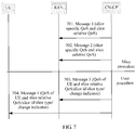
- the method includes: receiving, by a core network control plane network element CN-CP, air interface side quality of service QoS capability information and/or ground side QoS capability information sent by a radio access network RAN; and determining selection or reselection of an air interface side road section or a ground side road section based on the air interface side QoS capability information and/or the ground side QoS capability information.
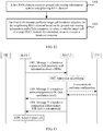
- a method for quality of service QoS control includes: receiving, by a first radio access network RAN element, ground side routing information sent by a neighboring RAN element, where the ground side routing information includes one or more of information about a serving gateway SGW connected to the neighboring RAN element, information about a packet data network gateway PGW, information about a packet data network PDN connected to the PGW, information about a local home network LHN, ultra-low delay capability information, and ultra-reliable transmission capability information; and performing, by the first RAN element, target cell handover selection on the neighboring RAN element based on the ground side routing information and a QoS parameter, to select a suitable target cell of a target RAN element for a terminal, so as to execute a handover program.
- the method further includes: sending, by the first RAN element, a first message to the target RAN element, where the first message carries the QoS parameter, handover reason information, and information about a target PDN, so that the target RAN element performs service admission determining based on the QoS parameter, the handover reason information, and the information about the target PDN that are carried in the first message.
- the method further includes:
- the method further includes: when receiving second messages returned by a plurality of target RAN elements, selecting, by the first RAN element, a target cell based on QoS parameter satisfaction levels carried in the second messages; and initiating a handover to the target cell.
- a device is provided.
- the device is used as a first device, and the device includes: a queuing unit, configured to perform, based on quality of service QoS information of the first device, queuing processing on data to be sent by a Packet Data Convergence Protocol PDCP entity, to obtain a queued queue, where each queue includes at least one flow; an obtaining unit, configured to obtain pre-scheduling window information of the PDCP entity; a determining unit, configured to determine pre-scheduling information of each queue queued by the queuing unit; and a pre-scheduling unit, configured to: perform pre-scheduling processing based on the pre-scheduling information that is of each queue and that is determined by the determining unit and the pre-scheduling window information obtained by the obtaining unit, and select, from the queued queue, a data packet of a pre-scheduling window size identified by the pre-scheduling window information.
- a queuing unit configured to perform
- the device further includes a generation unit, configured to: after the queuing unit performs queuing processing on a PDCP service data unit PDCP SDU and the pre-scheduling unit performs pre-scheduling processing, perform PDCP sequence number PDCP SN number allocation, ciphering, and PDCP header adding to obtain a PDCP protocol data unit PDCP PDU; or allocate a PDCP SN number to a PDCP SDU, and after the queuing unit performs queuing processing and the pre-scheduling unit performs pre-scheduling processing, perform ciphering and PDCP header adding to obtain a PDCP PDU; or perform PDCP SN number allocation, ciphering, and PDCP header adding on a PDCP SDU before the queuing unit performs queuing processing and the pre-scheduling unit performs pre-scheduling processing to obtain a PDCP PDU.
- a generation unit configured to: after the queuing unit
- the device further includes a delivery unit, configured to: deliver the PDCP PDU generated by the generation unit to a Radio Link Control RLC entity for processing; perform, by the RLC entity, segmentation or concatenation on the PDCP PDU, and place the PDCP PDU in a Media Access Control MAC layer; and perform, by the MAC layer, scheduling and multiplexing on data of a plurality of logical channels LCHs to obtain a MAC protocol data unit MAC PDU, and deliver the MAC PDU to a physical layer for processing and sending.
- a delivery unit configured to: deliver the PDCP PDU generated by the generation unit to a Radio Link Control RLC entity for processing; perform, by the RLC entity, segmentation or concatenation on the PDCP PDU, and place the PDCP PDU in a Media Access Control MAC layer; and perform, by the MAC layer, scheduling and multiplexing on data of a plurality of logical channels LCHs to obtain a MAC protocol data unit MAC PDU, and deliver
- the obtaining unit is further configured to obtain the QoS information of the first device from a core network CN or a radio access network RAN before the queuing unit performs queuing processing on the to-be-sent data based on the QoS information of the first device, where the QoS information of the first device includes one or more of a quality of service class identifier QCI, a guaranteed rate GBR, a maximum bit rate MBR, an access point aggregate maximum bit rate APN-AMBR, a user equipment aggregate maximum bit rate UE-AMBR, and an allocation and retention priority ARP; and the delivery unit is further configured to deliver the QoS information of the first device that is obtained by the obtaining unit to the PDCP entity of the first device.
- the QoS information of the first device includes one or more of a quality of service class identifier QCI, a guaranteed rate GBR, a maximum bit rate MBR, an access point aggregate maximum bit rate APN-AMBR, a user equipment aggregate maximum bit rate UE-AMBR, and an allocation
- the QCI indicates one or more of counters such as a priority, a delay, and a packet loss rate
- the QoS information is at a bearer level, a flow level, a packet level, or a user equipment UE level.
- the obtaining unit is further configured to: before the queuing unit performs queuing processing on the to-be-sent data based on the QoS information of the first device, obtain the QoS information that is of the first device and that is adjusted based on relative QoS information of a slice to which a service belongs.
- the obtaining unit is further configured to: before obtaining the QoS information that is of the first device and that is adjusted based on the relative QoS information of the slice to which the service belongs, obtain, based on an identifier of the slice to which the service belongs, QoS information of the slice to which the service belongs, where the QoS information of the slice includes specific QoS information of the slice and/or the relative QoS information of the slice; and the device further includes a processing unit, configured to: prepare a resource for the slice based on the specific QoS information that is of the slice and that is obtained by the obtaining unit; and/or adjust the QoS information of the first device based on the relative QoS information of the slice.
- the QoS information that is of the slice and that is obtained by the obtaining unit further includes information indicating whether the relative QoS information of the slice is effective; and the processing unit is specifically configured to adjust the QoS information of the first device based on the relative QoS information of the slice when the QoS information that is of the slice and that is obtained by the obtaining unit includes information indicating that the relative QoS information of the slice is effective.
- the queuing unit is specifically configured to: filter data from an upper layer of the PDCP entity based on the flow-level QoS information of the first device, to obtain a flow-level data flow; or divide data from an upper layer of the PDCP entity based on the bearer-level QoS information of the first device, to obtain a flow-level data flow; or classify data from an upper layer of the PDCP entity based on the packet-level QoS information of the first device, to obtain a flow-level data flow.
- the obtaining unit is specifically configured to: obtain configuration information sent by the radio access network RAN, and set the pre-scheduling window information of the PDCP entity based on the configuration information; or receive the pre-scheduling window information of the PDCP entity that is periodically reported by the RLC entity; or receive the pre-scheduling window information of the PDCP entity that is reported by the RLC entity based on an event; or select independent pre-scheduling window information of the PDCP entity based on one or more of a length and a wait time of the queued queue and an RLC buffer status.
- the obtaining unit is specifically configured to select independent pre-scheduling window information based on one or more of a length and a wait time of the queued queue and an RLC buffer status, until the PDCP entity of the first device receives the pre-scheduling window information reported by the RLC entity or information that is reported by the RLC entity and that indicates that an RLC buffer has heavy load, and selects the pre-scheduling window information based on a status of the RLC buffer.
- the delivery unit is specifically configured to: if one PDCP entity corresponds to a plurality of RLC entities, group, by the PDCP entity, queued queues of the PDCP entity based on different types of RLC entities, and deliver data in each group of queues to a corresponding type of RLC entity; or if one PDCP entity corresponds to a plurality of RLC entities, select, by the PDCP entity based on a time order of reporting pre-scheduling window information by RLC entities, an RLC entity to which the PDCP PDU is to be delivered; or if a plurality of PDCP entities correspond to one RLC entity, generate, by the RLC entity, a plurality of pieces of pre-scheduling window information and notify the plurality of pieces of pre-scheduling window information to a plurality of corresponding PDCP entities, and independently perform, by each PDCP entity, pre-scheduling processing, and send the PDCP PDU to the RLC entity; or allocate
- the determining unit is specifically configured to: obtain pre-scheduling information, of the PDCP entity, that is of each data flow and that is sent by the radio access network RAN; and/or obtain the flow-level QoS information of the first device that is sent by the core network CN, and determine pre-scheduling information, of the PDCP entity, of each data flow based on the flow-level QoS information of the first device; and/or obtain information from the upper layer of the PDCP entity to calculate pre-scheduling information of the PDCP entity.
- the delivery unit is specifically configured to perform, by the RLC entity, data packet segmentation and concatenation to generate a Media Access Control protocol data unit MAC PDU of a fixed size, for buffering by the MAC layer.
- the determining unit is further configured to determine the fixed size of the MAC PDU; and the device further includes a sending unit, configured to send the fixed size to a second device, so that when allocating a resource to the first device, the second device allocates a resource that can be used to transmit data of the fixed size or data of a size that is an integer multiple of the fixed size.
- the device further includes a receiving unit, configured to receive a fixed size that is of a MAC PDU and that is determined by a second device and sent by the second device; and the delivery unit is specifically configured to instruct the RLC entity to perform data packet segmentation and concatenation based on the received fixed size, to generate the MAC PDU of the fixed size.
- the delivery unit is specifically configured to: instruct the RLC entity to perform data packet segmentation and concatenation to generate a plurality of MAC PDUs of the fixed size; generate, by the MAC layer, a plurality of buffer queues, where the queues correspond to different fixed sizes; and obtain, by the MAC layer, a data packet from a corresponding queue based on a received resource size status.
- one PDCP entity of the first device corresponds to a plurality of RLC entities
- the delivery unit is specifically configured to deliver, by the PDCP entity of the first device, a PDCP PDU to each RLC entity for processing.
- a plurality of PDCP entities of the first device correspond to one RLC entity
- the delivery unit is specifically configured to deliver, by each PDCP entity of the first device, a PDCP PDU to the RLC entity for processing.
- the delivery unit is specifically configured to: instruct the MAC entity to obtain scheduling information that is of each radio bearer RB and that is configured by a RAN element; or obtain scheduling information of each RB based on the pre-scheduling information according to a preset calculation rule; and perform, by the MAC layer, scheduling and multiplexing on the data of the plurality of logical channels LCHs based on the scheduling information of the RB.
- the obtaining unit is specifically configured to: obtain a QoS parameter of a first road section in which the first device is located; or obtain an end-to-end E2E QoS parameter of the first device and a rule for dynamically allocating the E2E QoS parameter.
- the device further includes: a receiving unit, configured to receive a capability or load notification message from a control plane; and an adjustment unit, configured to: when it is determined, based on the capability or load notification message received by the receiving unit, that a QoS capability of a road section other than the first road section does not satisfy a QoS requirement of the road section, adjust the QoS parameter of the first road section of the first device to improve quality of service of the first road section, so as to satisfy E2E QoS.
- a receiving unit configured to receive a capability or load notification message from a control plane
- an adjustment unit configured to: when it is determined, based on the capability or load notification message received by the receiving unit, that a QoS capability of a road section other than the first road section does not satisfy a QoS requirement of the road section, adjust the QoS parameter of the first road section of the first device to improve quality of service of the first road section, so as to satisfy E2E QoS.
- the device further includes: a receiving unit, configured to receive an in-band notification message from a user plane, where the in-band notification message carries QoS satisfaction information, and the QoS satisfaction information is used to indicate an occupied proportion or quantity of an E2E QoS counter or a remaining proportion or quantity of an E2E QoS counter; and an adjustment unit, configured to: when it is determined, based on the QoS satisfaction information, that QoS is not satisfied in a road section other than the first road section, adjust the QoS parameter of the first road section of the first device to improve quality of service of the first road section, so as to satisfy E2E QoS.
- a receiving unit configured to receive an in-band notification message from a user plane, where the in-band notification message carries QoS satisfaction information, and the QoS satisfaction information is used to indicate an occupied proportion or quantity of an E2E QoS counter or a remaining proportion or quantity of an E2E QoS counter
- an adjustment unit configured to: when it is determined,
- a core network device includes: a receiving unit, configured to receive air interface side quality of service QoS capability information and/or ground side QoS capability information sent by a radio access network RAN; and a determining unit, configured to determine selection or reselection of an air interface side road section or a ground side road section based on the air interface side QoS capability information and/or the ground side QoS capability information received by the receiving unit.
- an access network device includes: a receiving unit, configured to receive ground side routing information sent by a neighboring radio access network RAN element, where the ground side routing information includes one or more of information about a serving gateway SGW connected to the neighboring RAN element, information about a packet data network gateway PGW, information about a packet data network PDN connected to the PGW, information about a local home network LHN, ultra-low delay capability information, and ultra-reliable transmission capability information; and a handover unit, configured to perform target cell handover selection on the neighboring RAN element based on the ground side routing information received by the receiving unit and a quality of service QoS parameter, to select a suitable target cell of a target RAN element for a terminal, so as to execute a handover program.
- a receiving unit configured to receive ground side routing information sent by a neighboring radio access network RAN element, where the ground side routing information includes one or more of information about a serving gateway SGW connected to the neighboring RAN element, information about a packet data network gateway PGW, information about
- the access network device further includes a sending unit, configured to send a first message to the target RAN element, where the first message carries the QoS parameter, handover reason information, and information about a target PDN, so that the target RAN element performs service admission determining based on the QoS parameter, the handover reason information, and the information about the target PDN that are carried in the first message.
- a sending unit configured to send a first message to the target RAN element, where the first message carries the QoS parameter, handover reason information, and information about a target PDN, so that the target RAN element performs service admission determining based on the QoS parameter, the handover reason information, and the information about the target PDN that are carried in the first message.
- the receiving unit may be further configured to: receive a second message sent by the target RAN element, where the second message is used to indicate that admission succeeds, and the second message carries a QoS parameter satisfaction level; or receive a third message sent by the target RAN element, where the third message is used to indicate that admission fails, and the third message carries a specific cause.
- the handover unit is further configured to: when the receiving unit receives second messages returned by a plurality of target RAN elements, select a target cell based on QoS parameter satisfaction levels carried in the second messages; and initiate a handover to the target cell.
- an embodiment of the present invention provides a device.
- the device may be user equipment, an access network device, or a core network device, the device may implement functions performed by the device in the foregoing method example, and the functions may be implemented by hardware or by hardware executing corresponding software.
- the hardware or the software includes one or more modules corresponding to the functions.
- a structure of the device includes a memory, a processor, and a transceiver.
- the processor is configured to support the device in performing a corresponding function in the foregoing method.
- the transceiver is configured to support the device in sending or receiving data or an instruction.
- the memory is configured to be coupled to the processor, and stores a program instruction and data required by the device.
- an embodiment of the present invention provides a system.
- the system includes the foregoing user equipment, the foregoing access network device, and the foregoing core network device.
- an embodiment of the present invention provides a computer storage medium, configured to store a computer software instruction used by the foregoing device.
- the computer software instruction includes a program designed to execute the foregoing aspects.
- a PDCP entity when a device needs to send data, a PDCP entity first performs pre-scheduling, and then a MAC layer performs scheduling, instead of performing scheduling by the MAC layer only once.
- Flow-based QoS control is implemented through the two times of scheduling.
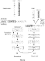
- FIG. 3 is a schematic diagram of a system architecture on which a method for QoS control is based according to an embodiment of the present invention.
- the present invention may be applied to a 5G communications system and a subsequent evolved communications system, and a mobile communications system such as LTE, 3G, 2G, Wi-Fi, and WiMAX.
- a specific application scenario of the method may be a single connectivity scenario, a dual connectivity scenario, a relay (Relay) scenario, or a device-to-device (Device-to-Device, D2D) scenario.
- the system mainly includes UE 301, a RAN 302, a CN-control plane (Control Plane, CP) 303, a CN-user plane (User Plane, UP) 304, and a public data network (Public Data Network, PDN) 305.
- Network elements in the present invention include a RAN element, a core network element, a terminal device, and an application server.
- the RAN element mainly includes: a RAN controller that is responsible for RAN control, including functions such as resource allocation and mobility management; and a base station with a control plane, a user plane, and functions such as service creation and mobility and user data scheduling.
- the core network element mainly includes: a control plane network element used for functions such as terminal session management, mobility management, QoS control, and subscription information management; and a user plane network element that has functions such as data forwarding and that may include an SGW (serving gateway) and a PGW (PDN gateway).
- the terminal device has functions such as data sending, data reception, and measurement.
- the application server provides an application-level service requirement.
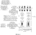
- FIG. 3a is a schematic diagram of a possible RAN network architecture according to an embodiment of the present invention.
- a RAN element may include two parts: a centralized unit (central unit, CU) and a distributed unit (distribute Unit, DU), the CU and the DU implement a RAN function together, and a new radio (next radio, NR) gNB includes two parts: a CU and a DU.
- a centralized unit central unit, CU
- DU distributed unit
- CU and the DU implement a RAN function together
- a new radio (next radio, NR) gNB includes two parts: a CU and a DU.
- a RAN protocol stack is also separately deployed in the CU and the DU. Possible distribution manners are as follows: In Option (Option) A, a radio resource control (Radio Resource Control, RRC) functional entity and a PDCP functional entity are deployed in the CU, and an RLC functional entity, a MAC functional entity, a physical layer (Physical Layer protocol, PHY) functional entity, and a radio frequency (Radio Frequency, RF) unit functional entity are deployed in the DU.
- RRC Radio Resource Control
- PDCP Packet Control
- RLC Radio Link Control
- MAC Physical Layer protocol
- PHY Physical Layer protocol
- RF radio frequency
- an RRC functional entity and a PDCP functional entity are deployed in the CU, some RLC functions (functions of retransmission and possible segmentation) are in the CU, and remaining RLC functions (functions such as segmentation and reassembly), a MAC functional entity, a PHY functional entity, and an RF functional entity are deployed in the DU.
- an RRC functional entity, a PDCP functional entity, and an RLC functional entity are deployed in the CU, and a MAC functional entity, a PHY functional entity, and an RF functional entity are deployed in the DU.
- an RRC functional entity and a PDCP functional entity are deployed in the CU, and a MAC functional entity, a PHY functional entity, and an RF functional entity are deployed in the DU.
- An ARQ retransmission function is implemented by the PDCP entity, and functions of segmentation and concatenation are implemented by the MAC layer in the DU.
- a method for QoS control provided in the embodiments of the present invention may be applied to an uplink data processing procedure, or may be applied to a downlink data processing procedure.
- data sending processing is performed by UE, and data reception processing is performed on a RAN side.
- data reception processing is performed by the UE.
- the uplink data processing procedure is used as an example to describe the method for QoS control in detail.
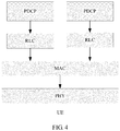
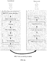
- FIG. 4 is a schematic structural diagram of composition of a UE-side protocol stack according to an embodiment of the present invention.
- the UE includes a PDCP entity, an RLC entity, a MAC layer, and a PHY layer.
- a pre-scheduling processing procedure is implemented at a PDCP layer or a protocol layer above the PDCP layer.
- a pre-scheduling processing protocol layer may be newly defined above the PDCP layer, to complete functions of the pre-scheduling processing procedure described in the present invention.
- the PDCP entity is mainly configured to process an RRC message from a control plane and an Internet Protocol (Internet Protocol, IP) packet or a non-IP packet from a data plane.
- a function of the PDCP entity includes any one or more of the following functions: ciphering and deciphering (Ciphering and deciphering) for user plane data and control plane data; integrity protection (Integrity Protection) only for control plane data; user data and control plane data transmission; reordering and retransmission processing during a handover (handover); and discarding user plane data because of a timeout.
- a function of the RLC entity includes any one or more of the following functions: RLC service data unit (Service Data Unit, SDU) segmentation (segmentation)/concatenation (concatenation) and reassembly (reassembly):
- the function is applicable only to an unacknowledged mode (unAcknowledged Mode, UM) and an acknowledged mode (Acknowledged Mode, AM).
- UM unacknowledged Mode
- AM acknowledged mode
- a transmit end needs to perform RLC SDU segmentation/concatenation, so that the RLC SDU fits the size specified by the MAC layer.
- a receive end needs to reassemble previously segmented RLC SDUs, to restore an original RLC SDU and send the original RLC SDU to an upper layer.
- Error correction performed by using an automatic repeat request (Automatic Repeat Request, ARQ): The function is applicable only to the AM mode, a hybrid automatic repeat request (Hybrid Automatic Repeat reQuest, HARQ) mechanism of the MAC layer is intended to implement very fast retransmission, and a feedback error rate of the mechanism is approximately 1%.
- a HARQ feedback error rate is quite high for some services such as Transmission Control Protocol (Transmission Control Protocol, TCP) transmission (requiring a packet loss rate to be less than 10 -5 ). For such services, retransmission processing at the RLC layer can further reduce the feedback error rate.
- TCP Transmission Control Protocol
- TCP Transmission Control Protocol
- retransmission processing at the RLC layer can further reduce the feedback error rate.
- Reordering performed on an RLC data PDU: The function is applicable only to the UM mode and the AM mode. A HARQ of the MAC layer may cause packets arriving at an RLC layer to be out of order. Therefore, data needs to be reordered by the RLC layer.
- Duplicate packet detection (duplicate detection): The function is applicable only to the UM mode and the AM mode. A most possible cause of occurrence of a duplicate packet is that the transmit end feeds back an acknowledgement (HARQ ACK), but the receive end incorrectly interprets the acknowledgement as a negative acknowledgement (NACK), resulting in unnecessary MAC PDU retransmission.
- HARQ ACK acknowledgement
- NACK negative acknowledgement
- Resegmentation (resegmentation) performed on an RLC data PDU The function is applicable only to the AM mode.
- resegmentation may also be required. For example, if a size specified by the MAC layer is less than that of an original RLC data PDU, resegmentation needs to be performed.
- a function of a MAC entity includes any one or more of the following functions: matching between a logical channel and a transport channel; multiplexing of a plurality of MAC SDUs belonging to one or different logical channels (radio bearers) to a same MAC PDU (Transport Block) and sending of the plurality of MAC PDUs to the physical layer; demultiplexing; error correction performed by using a HARQ; scheduling processing; logical channel priority processing; scheduling information reporting (only for a UE side and uplink), for example, BSR (buffer status report) reporting; and random access procedure processing.
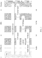
- FIG. 4 Composition of a protocol stack is shown in FIG. 4 .
- PDCP entities are in a one-to-one correspondence with RLC entities.
- RLC entities Refer to a schematic diagram of a correspondence between a PDCP entity and an RLC entity in FIG. 4a .
- one PDCP entity corresponds to a plurality of RLC entities, and each RLC entity corresponds to one logical channel.
- the MAC layer performs priority scheduling and multiplexing on data of a plurality of logical channels, and sends a multiplexed data packet MAC PDU to the physical layer for processing and sending. Queuing and pre-scheduling are performed between a plurality of flows in each PDCP entity.
- a correspondence between a flow and an RB may be fixedly configured by an AN, or may be selected by the UE.
- a selection rule may be configured by the AN.
- a concept of the RB may include only a fixed RLC entity.
- a plurality of RLC entities share one PDCP entity.
- PDCP entities may be classified into three types, respectively corresponding to three different types of RLC entities: a transparent mode (Transparent Mode, TM), a UM mode, and an AM mode.
- TM Transparent Mode
- UM mode UM mode
- AM mode AM mode
- functions of the PDCP entity and the RLC entity may be processed at one protocol layer.
- functions of the RLC entity may be separately implemented by the MAC entity and the PDCP entity.
- a correspondence between a PDCP entity and an RLC entity is a one-to-many mapping relationship.
- a correspondence between a PDCP entity and an RLC entity is a many-to-one mapping relationship.
- a correspondence between a PDCP entity and an RLC entity is a dynamic mapping relationship.
- functions of the RLC entity and the MAC entity may be processed at one protocol layer.
- the L2 protocol stack includes a PDCP layer, an RLC layer, and a MAC layer.
- Different distribution manners of L2 functions in different protocol stacks are not limited in the present invention, to be specific, different distribution manners of the L2 functions at the PDCP layer, the RLC layer, and the MAC layer are not limited.
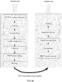
- FIG. 5 is a schematic diagram of a flow direction of a UE-side data flow according to an embodiment of the present invention.
- a data flow at an application layer first passes through a buffer (buffer), and then enters a PDCP entity.
- the PDCP entity pre-schedules the data flow, and when a specific transmission condition (transmission opportunity) is satisfied, a sending unit (send unit) disposed in the PDCP entity sends the data flow to an RLC entity.
- the RLC entity performs corresponding processing on the data flow and then sends a processed data flow to a MAC layer.
- a PHY layer finally sends the data flow by using an air interface.
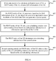
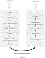
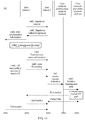
- FIG. 6 is a flowchart of a method for QoS control according to an embodiment of the present invention. The method is performed by UE, the UE is a data transmit end, and the method includes the following steps.
- Step 601 When data needs to be sent at an application layer of the UE, a PDCP entity of the UE obtains QoS information of the UE.
- the UE may obtain the QoS information of the UE from a CN or an AN.
- the QoS information includes one or more of a QCI, a GBR, an MBR, an access point aggregate maximum bit rate APN-AMBR, a user equipment aggregate maximum bit rate UE-AMBR, and an ARP.
- the UE transmits the obtained QoS information of the UE to the PDCP entity of the UE.
- the CN may notify the AN or the UE of the QoS information by using a control plane or a user plane or both.
- the QCI indicates one or more of counters such as a priority, a delay, and a packet loss rate
- the QoS information is at a bearer level, a flow level, a packet level, or a UE level.
- a network slice is a network resource slice. Different slices may belong to different tenants, different tenants require a network to provide different service levels, and QoS of users belonging to different slices may be different. Therefore, the QoS information and slice information need to be combined.
- the UE may further obtain relative QoS information of a slice to which a service belongs, and adjust the QoS information of the UE based on the relative QoS information of the slice.
- Step 602 The PDCP entity of the UE processes, based on the QoS information of the UE, the data to be sent at the application layer, to obtain a flow-level data flow.
- the PDCP entity of the UE may filter the data from the application layer based on the flow-level QoS information of the UE, to obtain the flow-level data flow; or the PDCP entity of the UE divides the data from the application layer based on the bearer-level QoS information of the UE, to obtain the flow-level data flow; or the PDCP entity of the UE classifies the data from the application layer based on the packet-level QoS information of the UE, to obtain the flow-level data flow.
- a core network element or the RAN configures an identifier flow id of the data flow.
- the flow id is added to the QoS information.
- Step 602 may be referred to as a generation procedure or a queuing procedure of a pre-scheduled queue. Each flow-level data flow corresponds to one queued queue.
- a plurality of data flows may correspond to a same queued queue, information about a correspondence between a plurality of data flows and one queue may be configured by a RAN element, and the RAN element may further configure a correspondence between a data flow id and a queue id.
- a plurality of data flows may correspond to a same queue based on same QoS information or a same priority in QoS information.
- the RAN does not configure a correspondence between a data flow and a queue, it may be considered that data flows are in a one-to-one correspondence with queues.
- a pre-scheduling data queue comes from application layer data, and the application layer data may be in a flow form, in other words, a flow-based QoS mechanism.
- the CN may notify the UE of flow QoS information, or the RAN notifies the UE of flow QoS information.
- the CN may notify the UE of a TFT template of each flow, and the UE filters data from the application layer by using the TFT template to obtain a plurality of flow-level data flows.
- the flow QoS information includes one or more of flow information such as a QCI, a GBR, a maximum rate, an APN-AMBR, a TFT template, an ARP, and a flow id.
- the QCI indicates one or more of counters such as a priority, a delay, and a packet loss rate.
- the TFT template means filtering a packet based on an IP 5-tuple and a QoS related field in an IP header.
- the filtering template may include one or more of an IPv4 remote address (IPv4 remote address), an IPv6 remote address (IPv6 remote address), a protocol identifier/next header (protocol identifier), a single local port (single local port number), a local port range (local port number range), a single remote port (single remote port number), a remote port range (remote port number range), a security parameter index (security parameter index), a type of service/traffic class (type of service), a flow label type (flow label type), and the like.
- the flow QoS information further includes aggregate QoS information of a plurality of flows, and the aggregate QoS information includes one or more of information such as a QCI, a GBR, a maximum rate, an APN-AMBR, an ARP, and a flow id, and represents an aggregation feature of a plurality of flows, for example, a rate limitation.
- aggregate QoS information is configured for a plurality of flows of a same application application.
- QoS information of each flow needs to be satisfied, and aggregate QoS information of a plurality of flows, for example, a limitation or a restriction on a total rate of the plurality of flows, also needs to be satisfied.
- the UE may report, to the network actively or as required by the network, capability information indicating whether flow-based QoS is supported, to indicate whether a flow-based QoS mechanism can be supported.
- the UE may report the capability information to the core network element or the RAN element by using an AS (Access Stratum) or NAS (Non-access Stratum) message.
- AS Access Stratum
- NAS Non-access Stratum
- the CN or the RAN notifies the UE of bearer QoS information, and the UE divides bearer data to obtain a flow-level data flow.
- a rule for dividing the bearer data may be a TFT template enhancement rule, a data packet header mapping rule, or the like. For example, a data packet header byte of one or more of HTTP protocols at a TCP layer, an IP layer, and an app layer is mapped to divide bearer data to obtain a plurality of flows.
- the CN or the RAN may further notify a flow id or a similar identifier corresponding to the division rule.
- the bearer QoS information includes one or more of bearer information such as a QCI, a GBR, a maximum rate, an APN-AMBR, an ARP, and a TFT template.
- the QCI indicates one or more of counters such as a priority, a delay, and a packet loss rate.
- the CN or the AN may notify the UE of packet QoS information, and the UE classifies packets to obtain a flow-level data flow.
- a classification rule may be features of some bytes in a data packet header or identification information of a data packet header, for example, some special ports and feature fields in the TCP protocol, and keywords such as HTTP packet feature fields "GET", “POST”, “HTTP/1.1", and "HOST".
- Feature association is joint identification of a plurality of feature fields, and behavior identification means identifying a data flow behavior, for example, one or more of behavior modes such as a port range in a packet, packet length statistics (a packet length sequence, a packet length set, a packet length range, a packet length average, and a sum of round-trip packet lengths), a packet sending frequency, a packet reception and sending proportion, and a destination address scattering degree.
- the CN or the AN may further notify a flow id or a similar identifier corresponding to the classification rule. For example, it is learned, through classification by using the HTTP packet feature field "GET", that a flow id of the data flow is 1.
- labeling may be performed in a data packet header to indicate different QoS information.
- the transmit end may generate different queued queues based on labels.
- a label is carried in a data packet header, the label may be a flow id or a QoS information indication identifier, and a location of the label may be a data packet header or extension header.
- labeling may be performed by using space of 6 reserved bits in a TCP header, extension space in a GTPU header, and a DSCP field in IP.
- different DSCP field values correspond to different QoS parameters. For example, 00000001 identifies one set of QoS parameters and 00000011 identifies another set of QoS parameters. This is not limited herein.
- an extra header may be added, and labeling is performed in a header area.
- the flow-level data flow may be obtained with reference to one or more of the foregoing manners.
- Step 603 The PDCP entity of the UE sets a pre-scheduling window size and a sending period based on configuration information or information reported by an RLC entity.
- the PDCP entity of the UE may obtain the configuration information sent by the RAN, and set one or more of the pre-scheduling window and the sending period based on the configuration information; or the PDCP entity of the UE receives one or more of the pre-scheduling window and the sending period that are periodically reported by the RLC entity; or the PDCP entity of the UE receives one or more of the pre-scheduling window and the sending period that are reported by the RLC entity based on an event.
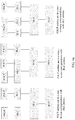
- FIG. 6a is a schematic diagram of a processing procedure of a PDCP entity according to an embodiment of the present invention.
- the PDCP entity receives data from an upper layer, performs operations such as queuing, pre-scheduling, PDCP SN number allocation, ciphering, and PDCP header adding, and then delivers a PDCP PDU to the RLC entity.
- the PDCP entity corresponds to a plurality of RLC entities, the PDCP entity needs to perform routing processing and select a suitable RLC entity to which the PDCP PDU is to be delivered.
- a PDCP entity receives data from a lower layer, performs operations such as PDCP header removal, deciphering, header decompression, and sequential delivery, and then delivers data to an upper layer.
- FIG. 6b is a schematic diagram of another processing procedure of a PDCP entity according to an embodiment of the present invention.
- the PDCP entity receives data from an upper layer, and performs operations such as PDCP SN number allocation, queuing, pre-scheduling, ciphering, and PDCP header adding, and then may deliver a PDCP PDU to the RLC entity.
- the PDCP entity corresponds to a plurality of RLC entities, the PDCP entity needs to perform routing processing and select a suitable RLC entity to which the PDCP PDU is to be delivered.
- a PDCP entity receives data from a lower layer, performs operations such as PDCP header removal, deciphering, header decompression, and sequential delivery, and then delivers data to an upper layer.
- FIG. 6c is a schematic diagram of still another processing procedure of a PDCP entity according to an embodiment of the present invention.
- the PDCP entity receives data from an upper layer, and performs operations such as PDCP SN number allocation, ciphering, PDCP header adding, queuing, and pre-scheduling, and then may deliver a PDCP PDU to the RLC entity.
- the PDCP entity may further perform a header compression function at the transmit end.
- a PDCP entity receives data from a lower layer, performs operations such as PDCP header removal, deciphering, header decompression, and sequential delivery, and then delivers data to an upper layer.
- a pre-scheduling window size needs to be set for sending data of different queues in the PDCP entity, and a sending period may be further set.
- the pre-scheduling window is used to indicate a total size of data packets extracted from queued queues.
- the PDCP entity delivers all data packets in the pre-scheduling window to the RLC entity.
- the PDCP entity may periodically perform delivery.
- the RAN configures one or more of the pre-scheduling window and the sending period of the PDCP entity.
- the RAN configures a set of pre-scheduling window information for each RB.
- the pre-scheduling window information includes one or more of a pre-scheduling window and a sending period.
- the RAN notifies the pre-scheduling window information of the RB to the UE by using an air interface message, for example, an RRC message or a PDCP control information element (PDCP control PDU).
- PDCP control PDU PDCP control information element
- the RLC entity periodically reports one or more of the pre-scheduling window and the sending period of the PDCP entity.
- the RAN may configure a period of reporting the pre-scheduling window information by the RLC entity.
- the RLC entity may calculate the pre-scheduling window information by using one or more of an RLC buffer status, a MAC layer scheduling opportunity, and an RLC entity throughput.
- the RLC entity may report the pre-scheduling window information of the PDCP based on an event, and the pre-scheduling window information includes one or more of the pre-scheduling window and the sending period.
- the RLC entity instructs the PDCP entity to enlarge the pre-scheduling window and/or shorten the sending period; or if the RLC buffer is greater than a threshold, the RLC entity instructs the PDCP entity to shrink the pre-scheduling window and/or extend the sending period.
- a message reported by the RLC entity to the PDCP entity may carry a suggested pre-scheduling window and a suggested sending period of the PDCP entity.
- An event for reporting the pre-scheduling information by the RLC entity may be configured by the RAN, and notified to the UE by using a control plane message or a user plane message.
- a control plane message or a user plane message For example, that the RLC buffer is less than a specified threshold within a specified time may be defined as an event A, triggering the RLC entity to report information to the PDCP entity, to instruct to enlarge the pre-scheduling window and/or shorten the sending period.
- That the RLC buffer is greater than a specified threshold within a specified time may be defined as an event B, triggering the RLC entity to report information to the PDCP entity, to instruct to enlarge the pre-scheduling window and/or shorten the sending period.
- the PDCP entity may report queuing information, for example, one or more of information such as a queue length and a queuing time, to the RLC layer.
- the RLC entity may calculate the pre-scheduling window information with reference to the queuing information reported by the PDCP entity.
- the RLC entity may report only index information of the pre-scheduling window information.
- the RAN or the RLC entity may preconfigure a plurality of sets of pre-scheduling window information, the pre-scheduling window information includes one or more of the pre-scheduling window and the sending period, and the index information is used to indicate specific corresponding pre-scheduling window information, thereby reducing signaling interaction overheads.
- the PDCP entity receives the pre-scheduling window information reported by the RLC entity, and updates old pre-scheduling window information to the newly received pre-scheduling window information.
- a maximum buffer of the RLC entity may be configured by the RAN.
- the PDCP entity may further independently select and adjust the pre-scheduling window information, and the PDCP entity may adaptively select independent pre-scheduling window information based on one or more of information such as a length and a wait time of the queued queue and an RLC buffer status.
- the pre-scheduling window information may be classified into several levels, and the PDCP entity may select a level of independent pre-scheduling window information.
- a plurality of levels of pre-scheduling window information may be configured by the RAN.
- a plurality of levels of independent pre-scheduling window information may be alternatively configured by the RLC entity.
- the RLC entity may report the RLC buffer status to the PDCP layer periodically or based on an event.
- the RLC buffer status may be buffer load status information, for example, a heavy, medium, or light load state.
- An event for reporting the RLC buffer status may be configured by the RAN element.
- the RLC entity reports the RLC buffer status through event triggering when the buffer status changes. Thresholds for the heavy, medium, and light load states of the RLC buffer may be configured by the RAN.
- a value of a period for periodically reporting the buffer status by the RLC entity may also be configured by the RAN.
- the PDCP entity may select a level of independent pre-scheduling window information based on the RLC buffer status. For example, if the RLC buffer is in a heavy load state, the PDCP entity selects a level of independent pre-scheduling window information corresponding to a relatively small pre-scheduling window.
- the PDCP entity may report queuing information, for example, one or more of information such as a queue length and a queuing time to, the RLC layer.
- the manner of reporting the pre-scheduling window information by the RLC entity and the manner of using the independent pre-scheduling window information by the PDCP entity may be used in combination. For example, when load of the RLC buffer is relatively light, the manner of using the independent pre-scheduling window information by the PDCP entity may be used to accelerate data sending. When load of the RLC buffer is relatively heavy, the RLC entity may report the pre-scheduling window information, and the PDCP entity uses the received pre-scheduling window information reported by the RLC entity.
- the manner of using the independent pre-scheduling window information of the PDCP entity may be used until the RLC entity reports the pre-scheduling window information or the RLC entity reports information indicating that load of the RLC buffer is heavy, and then a level of pre-scheduling window information is selected based on an RLC buffer status.
- classification processing may be performed based on flow pre-scheduling information.
- the manner of using the independent pre-scheduling window information of the PDCP entity may be used for queues corresponding to some flows.
- the flow pre-scheduling information may be configured by the RAN or notified by the RLC entity.
- the RAN may configure a case in which queues corresponding to flows with priorities 1 and 2 may be pre-scheduled in the manner of using the independent pre-scheduling window information of the PDCP entity.
- the PDCP entity notifies the independent pre-scheduling window information to the RLC entity.
- the RLC entity may determine, with reference to the independent pre-scheduling window information, the pre-scheduling window information generated by the RLC entity.
- the RAN or the RLC entity may configure a case in which queues of some flows are not pre-scheduled.
- data of the flows that is, a PDCP SDU
- processing such as PDCP SN number allocation, ciphering, and header adding is performed by the PDCP layer to obtain a PDCP PDU, and the PDCP PDU is directly delivered to the RLC entity.
- a procedure in FIG. 6a shows a manner of combining the manner of using the independent pre-scheduling window information by the PDCP entity and the manner of reporting the pre-scheduling window information by the RLC entity.
- the PDCP entity performs pre-scheduling processing based on the independent pre-scheduling window information, to obtain and buffer a to-be-sent PDCP PDU.
- the PDCP entity receives the pre-scheduling window information reported by the RLC entity, selects a specific quantity of PDCP PDUs from the to-be-sent PDCP PDU in a buffer in ascending order of PDCP SN numbers, and delivers the specific quantity of PDCP PDUs to the RLC entity.
- the specific quantity of PDCP PDUs is determined based on the pre-scheduling window information reported by the RLC entity. For example, if a quantity of to-be-sent PDCP PDUs is greater than a pre-scheduling window reported by the RLC entity, the specific quantity may be the pre-scheduling window size; or if a quantity of to-be-sent PDCP PDUs is less than or equal to a pre-scheduling window reported by the RLC entity, the specific quantity may be the quantity of to-be-sent PDCP PDUs in the buffer.
- an inter-layer window is implemented inside the protocol layer.
- RLC entity may be separately implemented by a MAC entity and the PDCP entity, for example, an RLC retransmission function is implemented by the PDCP entity, and segmentation and reassembly functions of the RLC entity are implemented by the MAC layer, a related function of reporting the pre-scheduling window information by the RLC entity may be implemented by the MAC layer.
- the PDCP entity If one PDCP entity corresponds to a plurality of RLC entities, the PDCP entity performs pre-scheduling processing based on pre-scheduling window information of the plurality of RLC entities, and sends the PDCP PDU to a corresponding RLC entity.
- the PDCP entity may group queued queues of the PDCP entity based on different types of RLC entities. For example, the PDCP entity groups the queues into two groups based on corresponding types of RLC entities, and delivers data in each group of queues to a corresponding type of RLC entity, in other words, performs routing processing at the transmit end.
- a pre-scheduling procedure may be performed in the manner of reporting the pre-scheduling window information by the RLC entity and/or the manner of using the independent pre-scheduling window information of the PDCP entity.
- the PDCP entity may not group queued queues, and selects an RLC entity and delivers data to the RLC entity.
- the PDCP entity may determine, based on pre-scheduling window information reported by a plurality of RLC entities, a quantity of PDCP PDUs delivered to different RLC entities, for example, select, in a time order of reporting the pre-scheduling window information by the RLC entities, an RLC entity to which the PDCP PDU is to be delivered.
- a quantity of PDCP PDUs to be delivered to different RLC entities may be determined based on one or more of radio link channel state information corresponding to the different RLC entities, buffer status information of the RLC entities, retransmission status information of the RLC entities, and the like.
- the RLC entity needs to notify the retransmission status information of the RLC entity to the PDCP entity, and the retransmission status information of the RLC entity may be one or more of information about the RLC entity such as a quantity of retransmitted RLC PDUs, or a retransmission probability or a total quantity of retransmission times of the RLC PDUs in a preset time period.
- the RLC entity If a plurality of PDCP entities correspond to one RLC entity, the RLC entity generates a plurality of pieces of pre-scheduling window information and notifies the plurality of pieces of pre-scheduling window information to a plurality of corresponding PDCP entities, and each PDCP entity independently performs pre-scheduling processing, and sends the PDCP PDU to the RLC entity.
- Identification information of the PDCP entity may be carried in the PDCP PDU.
- Another form of correspondence between a PDCP entity and an RLC entity is established.
- An RLC entity at the receive end delivers the PDCP PDU to a corresponding PDCP entity based on an obtained identifier of the PDCP entity.
- the RLC entity may allocate the pre-scheduling window information based on status information of the PDCP entity.
- the status information of the PDCP entity is one or more of a queue length and a queuing time of the queue in the PDCP entity, pre-scheduling information of data of each flow, and the like.
- the RAN may configure configuration information (including one or more of information such as a PBR, a priority, a max rate, a GBR, and Bucket Size Duration) for the PDCP entity, and notify the scheduling information to the RLC entity.
- the PDCP entity may combine pre-scheduling information of data of all the flows to generate scheduling information of the PDCP entity, for example, average priorities of a plurality of flows to obtain a priority of the PDCP entity, and add PBRs of the plurality of flows together to obtain a PBR of the PDCP entity.
- a combination rule for combining the pre-scheduling information of the data of all the flows to generate the scheduling information of the PDCP entity may be notified by the RAN.
- the PDCP entity notifies the scheduling information of the PDCP entity to the RLC entity.
- the RLC entity may allocate pre-scheduling window information to a plurality of PDCP entities based on status information of the PDCP entities and/or scheduling information of the PDCP entities, for example, allocate a total quantity of PDCP PDUs acceptable by the RLC entity to the plurality of PDCP entities, to obtain the pre-scheduling window information of the plurality of PDCP entities.
- PDCP entities are differentiated from each other based on priorities, to determine different pre-scheduling manners.
- PDCP entities with different scheduling priorities use different pre-scheduling manners.
- a high-priority PDCP entity may use the manner of using the independent pre-scheduling window information
- a low-priority PDCP entity may use the manner of reporting the pre-scheduling window information by the RLC entity.
- a priority of a PDCP entity that may use the independent pre-scheduling window information may be configured by the RAN.
- a PDCP entity with a priority greater than a specific priority may deliver the PDCP PDU to the RLC entity through independent pre-scheduling.
- a priority of a PDCP entity that uses the independent pre-scheduling window information may be configured by the RLC entity of the UE.
- the RAN element or the RLC entity may directly indicate a PDCP entity that performs independent pre-scheduling.
- An identifier of the PDCP entity may be carried.
- the RAN element or the RLC entity indicates that a PDCP entity 1 may perform independent pre-scheduling, in other words, perform pre-scheduling by independently selecting scheduling window information.
- the PDCP entity obtains a specific quantity of PDCP SDUs from the queue based on the pre-scheduling window information, performs processing such as PDCP SN number allocation, ciphering, and heading adding to obtain a PDCP PDU, and directly delivers the PDCP PDU to the RLC entity.
- processing such as PDCP SN number allocation, ciphering, and header adding has been performed on the queue
- the PDCP entity obtains a specific quantity of PDCP PDUs from the queue based on the pre-scheduling window information, and delivers the specific quantity of PDCP PDUs to the RLC entity.
- a correspondence between a PDCP entity and an RLC entity is a dynamic mapping relationship, the PDCP entity sends the PDCP PDU to a corresponding RLC entity based on an identifier of the RLC entity.
- Step 604 The PDCP entity of the UE determines pre-scheduling information of each data flow.
- the PDCP entity of the UE may obtain the pre-scheduling information that is of each data flow and that is sent by the RAN; and/or the PDCP entity of the UE obtains the flow-level QoS information of the UE that is sent by the CN, and determines the pre-scheduling information of each data flow based on the flow-level QoS information of the UE; and/or the PDCP entity of the UE obtains information from the application layer to calculate the pre-scheduling information.
- the PDCP entity of the UE may obtain the pre-scheduling information configured by the RAN.
- the RAN configures pre-scheduling information for data of the UE by using an air interface message.
- the pre-scheduling information includes one or more of information of each flow, for example, a PBR, a priority, a max rate, a GBR, an AMBR of an RB to which the flow belongs, an APN-AMBR, and bucket size duration.
- the PBR is a nominal rate, indicating rate assurance for each flow during scheduling, to avoid a case in which some low-priority queues are unable to be scheduled all the time and therefore data cannot be sent for a long time.
- the AMBR of the RB to which the flow belongs may be generated by the RAN, and indicates a maximum sending rate of all non-GBR services of the RB.
- the RAN may obtain the AMBR of the RB based on an AMBR of the UE.
- An air interface message for the pre-scheduling information sent by the RAN to the UE includes a flow identifier.
- the air interface message may be an RRC (radio resource connection) message or a PDCP control information element (PDCP control PDU).
- the pre-scheduling information further includes a scheduling algorithm and/or an algorithm type used when scheduling is performed on different queues.
- pre-scheduling information of a data flow is pre-scheduling information of a queue.
- information that is about a plurality of flows and that may be processed in combination may be further included. For example, if a plurality of flows have a same priority, the plurality of flows may be placed in a same queue for processing, in other words, uniform flow pre-scheduling information may be configured.
- a plurality of data flows correspond to a same queued queue.
- Pre-scheduling information of the plurality of flows corresponds to pre-scheduling information of the queue.
- the PDCP entity of the UE may obtain the pre-scheduling information notified by the CN.
- the CN notifies QoS information to the UE.
- the QoS information notified to the UE includes one or more of flow information such as a QCI, a GBR, a maximum rate, and an APN-AMBR, and the QCI indicates one or more of counters such as a priority, a delay, and a packet loss rate.
- the UE obtains the pre-scheduling information based on the flow-level QoS information by using a specific algorithm. For example, the UE may learn a priority of a to-be-scheduled flow through mapping by using QCI information.
- the RAN may notify a rule for calculating the pre-scheduling information to the UE, and the UE calculates and obtains the pre-scheduling information according to the rule. Further, the RAN may notify a part of the pre-scheduling information to the UE, and the UE may receive the part of the pre-scheduling information that is sent by the AN, and use the part of the pre-scheduling information as a part of pre-scheduling information of the UE.
- the PDCP entity of the UE may obtain the pre-scheduling information obtained from the app layer.
- the UE may obtain the information from the app layer to calculate the pre-scheduling information, and the UE reads the information from the app layer to obtain pre-scheduling related information, for example, for special processing on some application layer data, for example, special processing on a TCP retransmitted packet and a TCP ACK packet.
- a rule for reading information from APP to calculate the pre-scheduling information may be notified by the CN or the AN to the UE.
- the UE calculates the pre-scheduling information based on the obtained information from the app layer and the rule for the pre-scheduling information. For example, the TCP retransmitted packet and the TCP ACK packet may be placed in a high-priority queue.
- the foregoing three manners of obtaining the pre-scheduling information may be independently used or used in combination.
- Step 605 In each sending period, the PDCP entity of the UE selects a data packet of the pre-scheduling window size from the plurality of queues based on the pre-scheduling information of the queue.
- the PDCP entity further needs to ensure a prioritized bit rate (prioritized Bit Rate, PBR) of each queue, so as to prevent a queue from not being scheduled for a long time.
- PBR prioritized Bit Rate
- a maximum data scheduling rate is constrained by an APN-AMBR.
- one or more of information such as a queue length of service data, a queuing time of the queue, and a delay counter in a QoS attribute of a service may be considered. For example, scheduling of a data packet with a relatively long queuing time and a relatively small delay counter may be accelerated.
- step 602 There is no time order of performing step 602, step 603, and step 604.
- the PDCP entity in a data reception processing procedure on the RAN side, obtains a PDCP PDU from the RLC entity.
- the PDCP entity performs operations such as header removal and deciphering to obtain data packets of different flows, sequentially delivers the data packets to the upper layer, and sends the data packets to the core network through routing processing.
- queue pre-scheduling processing is performed at the PDCP layer, the RLC layer reports the pre-scheduling information (the pre-scheduling window and/or the sending period), and the PDCP entity performs scheduling and data delivery based on the pre-scheduling information.
- a fine-granularity QoS feature may be implemented above the MAC layer, so that a QoS requirement for fineness can be reflected, and MAC subheader overheads caused by an increase in a quantity of logical channels can be reduced.
- flow-based QoS control is implemented through both pre-scheduling by the PDCP layer and scheduling by the MAC layer.
- Scheduling information of each RB scheduled by the MAC layer includes one or more of RB information such as a logical information priority, a prioritized bit rate (prioritized Bit Rate, PBR), and bucket size duration (Bucket Size Duration, BSD).
- RB information such as a logical information priority, a prioritized bit rate (prioritized Bit Rate, PBR), and bucket size duration (Bucket Size Duration, BSD).
- the scheduling information of the RB may be configured by the RAN element, or may be obtained according to a preset calculation rule by using pre-scheduling information.
- the preset calculation rule is, for example, obtaining the logical information priority of the RB based on a priority of each flow in the RB. A manner of calculating an average may be specifically used.
- another part in the scheduling information of the RB may also be calculated by using scheduling information of a flow. For example, a value of the PBR may be a sum of PBRs of all flows.
- the preset calculation rule may be notified by the RAN element to the UE. In a scenario of flexible mapping between a flow and an RB, the scheduling information of the RB may be quickly obtained without dynamic configuration and update on the RAN side.
- the pre-scheduling information may be configured by a CU, and the scheduling information needs to be notified to a DU.
- the following procedure may be further performed:
- the PDCP entity of the UE processes a PDCP SDU to obtain a Packet Data Convergence Protocol protocol data unit PDCP PDU.
- a sending unit in the PDCP entity of the UE delivers the PDCP PDU to the RLC entity for processing.
- the RLC entity performs segmentation or concatenation on the PDCP PDU, and then places the PDCP PDU in the Media Access Control MAC layer.
- the MAC layer performs scheduling and multiplexing on data of a plurality of logical channels LCHs to obtain a Media Access Control protocol data unit MAC PDU, and delivers the MAC PDU to a physical layer for processing and sending.
- Transmit end flow differentiation Different flows are differentiated from each other in a TFT manner, and a TFT template corresponds to a flow id. Alternatively, different flows are identified through labeling, label information may be notified by the core network element to the UE, and the label information corresponds to a flow id.
- Receive end routing processing If a data packet includes a label, the RAN element obtains a tunnel identifier or a destination address based on the label, and sends the tunnel identifier or the destination address to a corresponding core network element; otherwise, if there is a TFT function, the RAN element performs a TFT operation to obtain a plurality of flows, and sends a data packet of each flow to a tunnel identifier or a destination address corresponding to the TFT template.
- the CN configures a correspondence between a TFT template and a tunnel identifier or a destination address of a flow, and notifies the correspondence to the RAN element.
- the CN configures a correspondence between a label in a data packet and a tunnel identifier or a destination address of a flow, and notifies the correspondence to the RAN element. Otherwise, the RAN element performs routing by using a destination IP address of the data packet, and sends the data packet to the core network element.
- Transmit end flow differentiation (1) If there is a tunnel such as a GTPU tunnel between the core network and the RAN, the RAN element at a transmit end may obtain different flows based on tunnel identifiers. (2) If a TFT is configured for the RAN, the RAN performs a TFT operation on data sent by the core network, and obtains corresponding flow data based on a TFT template (corresponding to a flow id). (3) If a data packet from the core network carries a label (corresponding to a flow id), the RAN element performs differentiation based on the label, to obtain flow data.
- Receive end routing processing The UE directly sends a PDCP SDU to an upper layer, namely, an application layer protocol entity of the UE.
- the PDCP entity may first perform PDCP SN number allocation on a PDCP SDU, perform queuing and queue pre-scheduling, place the PDCP SDU in the sending unit, and then perform ciphering and PDCP header adding to obtain a PDCP PDU.
- the PDCP entity may first perform PDCP SN number allocation on a PDCP SDU, perform ciphering and PDCP header adding to obtain a PDCP PDU, perform queuing and queue pre-scheduling, and place the obtained PDCP PDU in the sending unit.
- the RLC entity performs data packet segmentation and concatenation to generate a Media Access Control protocol data unit MAC PDU of a fixed size, for buffering by the MAC layer.
- MAC PDU Media Access Control protocol data unit
- a QoS parameter of the UE includes an air interface side QoS parameter of the UE and a ground side QoS parameter of the UE. That a PDCP entity of the UE obtains QoS information of the UE in step 601 specifically includes: obtaining, by the PDCP entity of the UE, the air interface side QoS parameter of the UE; or obtaining, by the PDCP entity of the UE, an end-to-end E2E QoS parameter of the UE and a rule for dynamically allocating the E2E QoS parameter.
- joint optimization may be performed based on section QoS.
- the UE receives a capability or load notification message from a control plane; and when determining, based on the capability or load notification message, that a ground side QoS capability does not satisfy a ground side QoS requirement, adjusts an air interface side QoS parameter of the UE to improve quality of service of an air interface side, so as to satisfy E2E QoS.
- the UE receives an in-band notification message from a user plane, where the in-band notification message carries QoS satisfaction information, and the QoS satisfaction information is used to indicate an occupied proportion or quantity of an E2E QoS counter or a remaining proportion or quantity of an E2E QoS counter; and when determining, based on the QoS satisfaction information, that ground side QoS is not satisfied, adjusts an air interface side QoS parameter of the UE to improve quality of service of an air interface side, so as to satisfy E2E QoS.
- FIG. 6d is a schematic diagram of pre-scheduling processing according to an embodiment of the present invention.
- the pre-scheduling processing occurs in an uplink data transmission procedure and is performed by the UE.
- a specific processing procedure is as follows: The UE initiates an uplink service, and the core network notifies QoS information of two flows to the RAN or the UE.
- the RAN receives the QoS information of the two flows from the UE, and generates pre-scheduling information through calculation.
- the pre-scheduling information includes one or more of information about the flow 1, for example, a PBR, a priority, an APN-AMBR, and bucket size duration and one or more of information about the flow 2, for example, a PBR, a priority, an APN-AMBR, and bucket size duration.
- the RAN element notifies the pre-scheduling information to the PDCP entity of the UE by using an air interface message.
- the PDCP entity of the UE groups data of the flow 1 and the flow 2 into two queues for queuing.
- PDCP entities are in a one-to-one correspondence with RLC entities in the scenario herein.
- the RLC entity reports pre-scheduling window information to the PDCP entity periodically or through event triggering, and the RLC entity may calculate the pre-scheduling window information by using information such as an RLC buffer status and a MAC layer scheduling opportunity.
- the MAC layer scheduling opportunity information is that the UE reports buffer status report (buffer status report, BSR) information to the RAN and the RAN allocates a UL grant to the UE.
- BSR buffer status report
- the RLC entity of the UE calculates the pre-scheduling window information based on the MAC layer information and the RLC buffer information.
- the PDCP entity of the UE pre-schedules the queued queues based on the pre-scheduling window information. For example, in view of factors such as a priority and a maximum rate limit (for example, RB-AMBR and APN-AMBR limitations), six data packets are selected from a queue of the flow 1, and four data packets are selected from a queue of the flow 2.
- the PDCP entity performs operations such as PDCP SN number allocation, ciphering, and PDCP header adding on the 10 data packets selected for pre-scheduling, to obtain a PDCP PDU, and delivers the PDCP PDU to the RLC entity. In a case of periodic sending, the foregoing operations are repeated when a next sending period arrives.
- the RLC entity After performing possible segmentation or concatenation processing on the PDCP PDU, the RLC entity delivers the PDCP PDU to the MAC layer for multiplexing.
- a PHY entity sends the PDCP PDU.
- the RLC entity of the RAN element at the receive end receives a data packet from the MAC layer.
- the RLC entity (AM mode) delivers a PDCP PDU to the PDCP entity, and the PDCP entity performs header removal and deciphering, and then delivers a PDCP SDU to an upper layer.
- data is sent to the core network through routing processing. If functions of the PDCP entity of the RAN element are distributed in the CU and functions of the RLC entity are distributed in the DU, the DU sends an uplink PDCP PDU to the CU by using an interface between the DU and the CU.
- the RAN element performs similar pre-scheduling processing.
- a specific procedure is as follows: For a downlink service, the core network triggers a service creation procedure, and notifies QoS information of the downlink service to the RAN by using a control plane or a user plane. The core network notifies QoS information of two flows to the RAN.
- the QoS includes QoS information of a slice.
- the RAN receives the QoS information of the two flows from the UE, and generates pre-scheduling information through calculation.
- the pre-scheduling information includes one or more of information about the flow 1, for example, a GBR 1, a priority 1, and bucket size duration 1 and one or more of information about the flow 2, for example, a GBR 2, a priority 2, and bucket size duration 2.
- the PDCP entity of the RAN element groups data of the flow 1 and the flow 2 into two queues for queuing.
- PDCP entities are in a one-to-one correspondence with RLC entities in the scenario herein.
- the PDCP entities are distributed in the CU, and the RLC entities are distributed in the DU.
- the RLC entity in the DU reports pre-scheduling window information to the PDCP entity periodically or through event triggering, and the RLC entity may calculate the pre-scheduling window information by using information such as an RLC buffer status and a MAC layer scheduling opportunity.
- the DU notifies the pre-scheduling window information to the CU by using an interface between the DU and the CU.
- the PDCP entity of the RAN pre-schedules the queued queues based on the pre-scheduling window information. For example, in view of factors such as a priority and a guaranteed rate, four data packets are selected from a queue of the flow 1, and eight data packets are selected from a queue of the flow 2.
- the PDCP entity performs operations such as PDCP SN number allocation, ciphering, and PDCP header adding on the 12 data packets selected for pre-scheduling, to obtain a PDCP PDU, and delivers the PDCP PDU to the RLC entity, to be specific, transmits the PDCP PDU by using the user plane of the interface between the CU and the DU. In a case of periodic sending, the foregoing operations are repeated when a next sending period arrives.
- the RLC entity After performing possible segmentation or concatenation processing on the PDCP PDU, the RLC entity delivers the PDCP PDU to the MAC layer for multiplexing. Then a PHY entity sends the PDCP PDU.
- the RLC entity of the UE at a receive end receives a data packet from the MAC layer.
- the RLC entity (AM mode) delivers a PDCP PDU to the PDCP entity, and the PDCP entity performs PDCP header removal and deciphering, and then delivers a PDCP SDU to the upper layer, namely, the application layer protocol entity of the UE.
- FIG. 6e-1 and FIG. 6e-2 are a schematic diagram of an overall network architecture of a method for flow-based QoS control according to an embodiment of the present invention. Processing procedures of the UE, the RAN, and the CN are shown in the figure.
- a CN may notify the QoS information of the slice to a RAN and a GW by using a control plane message or user plane data or both or in a preconfigured manner, and may further notify the QoS information of the slice to the UE by using a NAS message. Further, the RAN may notify the QoS information of the slice to the UE.
- the QoS information of the slice includes one or more of specific QoS information of the slice and relative QoS information of the slice.
- the specific QoS information of the slice indicates a resource and/or a user quality of experience (Quality of Experience, QoE) requirement of the slice, and may include one or more of information such as a QCI, an MBR and/or an AMBR, a GBR (which may indicate a lowest service requirement of the slice, and may be fixedly allocated), a priority (priority level), and an ARP.
- QCI indicates one or more of counters such as a priority, a delay, and a packet loss rate.
- a plurality of sets of specific QoS information may be configured for one slice, and are separately applicable to different network statuses.
- heavy, medium, and light load states may correspond to different QoS information.
- indication information in the specific QoS information of the slice may be used to indicate a network status to which each set of specific QoS information is applicable, and the indication information may be delivered along with the specific QoS information.
- the relative QoS information of the slice indicates a change of QoS information (including user-level QoS information and/or service-level QoS information) of a user that belongs to the slice.
- the relative QoS information of the slice may include one or more of a service priority increase or decrease, a minimum guaranteed rate increase or decrease of a service, a non-GBR service increase or decrease (for example, adding a PBR parameter), a service AMBR (APN-AMBR) adjustment, an increase or a decrease in an APN-AMBR of a user that belongs to the slice, a user UE-AMBR change, a service ARP information change, a service packet loss rate counter change, a service delay counter change, adding of a slice-level increment QoS parameter, and the like.
- the slice-level increment QoS parameter may include one or more of service-level QoS increments such as a slice-AMBR (indicating a maximum aggregated rate of all non-GBR services that belong to the slice), a time threshold for delaying reporting, a quantity of times uplink data can be reported, a data packet size (Data size), and information about an absolute report time (report absolute time) of data.
- the slice-level increment QoS parameter includes a user-level QoS increment parameter such as a user level.
- the user-level QoS information is user related QoS information, for example, one or more of a UE-AMBR, a user level, and the like.
- the service-level QoS information is QoS information of a single service, for example, may include one or more of a QCI, a GBR, a maximum rate, an ARP, and the like.
- a plurality of sets of relative QoS information may be configured for one slice, and are separately applicable to different network statuses.
- heavy, medium, and light load states may correspond to different relative QoS information.
- the relative QoS information of the slice may further include an identifier or a type of service information and/or user information, to indicate an effective range of the relative QoS information of the slice.
- the relative QoS information of the slice may include information indicating a network status in which the relative QoS information of the slice is effective, for example, a light, medium, or heavy load state of a cell.
- QoS information notified by the CN includes the QoS information of the slice.
- QoS information that is of a user or a service and that is generated by a core network element includes QoS information of a slice to which the user or the service belongs.
- the RAN and the UE receive the QoS information.
- the QoS information of the slice may be found by using a slice id.
- slice types may be used to indicate different changes of QoS information that belongs to the slice, and a predefined manner may be used. For example, a slice type 1 corresponds to a priority increase by two levels.
- FIG. 7 is a signal flow diagram of a slice QoS configuration method according to an embodiment of the present invention. Signaling interaction between UE, a RAN, and a CN-CP is included. The method includes the following steps.
- Step 701 The CN-CP sends a message 1 (for example, a slice setup request message) to the RAN, where the message 1 carries QoS information of a slice.
- a message 1 for example, a slice setup request message
- the RAN may further send a slice setup response message to the CN-CP after receiving the slice setup request message.
- Step 702 The CN-CP sends a message 2 (for example, a slice modify request message) to the RAN, where the message 2 carries the QoS information of the slice.
- a message 2 for example, a slice modify request message
- the QoS information of the slice includes one or more of specific QoS information of the slice and relative QoS information of the slice, and the message 1 and/or the message 2 may further carry a slice id or a slice type as an identifier.
- the RAN receives the QoS information of the slice.
- a CN or the RAN may notify the QoS information of the slice and/or the identifier of the QoS information to the UE.
- the RAN may prepare a resource for the slice based on the specific QoS information of the slice.
- the resource includes one or more of a hardware resource, a bandwidth resource, a storage resource, a radio resource, and the like of a base station.
- the RAN may configure different resources for the slice in different network statuses based on the specific QoS information of the slice.
- the RAN may modify, based on the relative QoS information of the slice, QoS information of a user that belongs to the slice.
- step 701 and step 702 are slice procedures.
- the method further includes the following procedure for obtaining slice related QoS information of a user:
- the CN may notify user QoS information, namely, the QoS information of the UE, to the RAN or the UE by using a control plane or a user plane or both.
- the user QoS information includes one or more of information such as a QCI, a GBR, a maximum rate, an APN-AMBR, a UE-AMBR, and an ARP.
- the QoS information may be at a bearer level, a flow level, a packet level, or a UE level.
- the slice id or the slice type may be further used to identify the relative QoS information of the slice.
- the CN may notify the QoS change indication information to indicate whether the user QoS information needs to change based on the relative QoS information of the slice.
- the indication information may further indicate a network status in which the user QoS information needs to change.
- the RAN or the UE receives service-level or UE-level QoS information, obtains the relative QoS information of the slice, and obtains a change to user QoS that is performed by using the relative QoS information of the slice based on network status information and the indication information, to obtain the user QoS information of the slice.
- the RAN or the UE performs resource allocation and scheduling based on the user QoS information, to satisfy a user requirement and further improve network resource utilization.
- FIG. 8 is a schematic diagram of one level of common caching processing.
- uplink scheduling needs to be performed 4 ms earlier mainly because of a processing delay of UE, including processing such as segmentation and concatenation by an RLC layer.
- a data packet is buffered by the RLC layer.
- a physical layer of the UE After receiving a scheduling resource, a physical layer of the UE notifies an upper layer.
- the RLC layer After performing operations such as segmentation and concatenation to adapt to a resource size, the RLC layer sends the data packet to a MAC layer.
- operations such as data packet segmentation and concatenation are performed earlier, to generate a MAC PDU of a fixed size, and the MAC PDU is buffered by a MAC layer.
- a base station allocates a resource that can be used to transmit data of the fixed size or data of a size that is an integer multiple of the fixed size.
- UE After receiving a UL grant (uplink grant), UE directly extracts the MAC PDU from a MAC cache queue, and sends the MAC PDU. In this way, a delay is reduced, and uplink data can be sent more quickly.
- FIG. 9 is a schematic diagram of two levels of caching processing according to an embodiment of the present invention. Two levels of buffer queues (RLC/MAC) are set.
- RLC/MAC buffer queues
- a method for determining whether to enable a function of "performing segmentation and concatenation earlier and buffering by a MAC layer" may be performed per bearer/stream/slice.
- whether the function is to be enabled may be independently configured for different bearers/streams/slices.
- UE reports information indicating whether the function needs to be enabled for each bearer/stream/slice, and indicates or suggests a volume of data that can be transmitted by using a resource allocated by a base station each time; or the base station determines whether the function needs to be enabled for each bearer/stream/slice, and indicates, to the UE, a determining result and a size of data that can be transmitted by using a resource allocated by the base station each time.
- the size of data may be one fixed size or a plurality of fixed sizes.
- the UE When the size of data is a plurality of fixed sizes, the UE generates a plurality of buffer queues, and the queues correspond to different fixed sizes.
- Each queue may be generated by performing segmentation and concatenation on different RLC data packets; or each queue may be generated by performing segmentation and concatenation on a same RLC data packet based on different fixed sizes by improving performance by using storage; and a data packet may be obtained from a corresponding queue based on a received resource size status.
- the UE requests a fixed RLC segment size by using a user plane or control plane message, and the user plane or control plane message may carry a suggested value.
- the base station determines the fixed RLC segment size, and notifies the fixed RLC segment size to the UE.
- fixed RLC segment sizes obtained by the UE are 10 bytes, 20 bytes, and 40 bytes.
- An RLC entity of the UE performs segmentation and concatenation on RLC PDUs in a buffer based on the fixed RLC segment sizes 10 bytes, 20 bytes, and 40 bytes, to obtain three queues that are respectively numbered 1, 2, and 3.
- the RLC entity delivers the three queues to the MAC layer, and the MAC layer buffers the RLC PDU queues after receiving the queues.
- the MAC layer After receiving a resource indication from a physical layer, the MAC layer selects a suitable queue based on the resource information for sending, for example, selects an RLC PDU in a queue 2 of the fixed segment size of 20 bytes, and places the RLC PDU in a MAC PDU for sending.
- a quantity of RLC PDUs in the queue 2 that are placed in the MAC PDU is determined by a MAC layer scheduling algorithm.
- the RLC layer performs segmentation and concatenation earlier to obtain one or more data packets of a fixed size, and the data packets are buffered by the MAC layer, thereby implementing quicker uplink scheduling.
- sectioning implementation and joint optimization may be performed on a QoS service, to ensure E2E QoS, so as to satisfy a service counter requirement.
- a sectioning operation of an E2E QoS parameter may be performed in either of the following two solutions:
- Solution 1 Fixed section QoS, and independent implementation of QoS in each road section
- a QoS counter is allocated to each road section based on an E2E QoS parameter.
- an E2E QoS parameter counter is separately allocated to a ground transmission section and an air interface transmission section.
- the E2E QoS parameter counter may include one or more of a delay (delay) counter, a packet loss rate (packet loss rate), an ARP, a GBR, an MBR, an AMBR, a priority, and the like.
- a range indicated by the E2E QoS parameter is a QoS requirement for a section from UE to a PDN GW.
- the PDN GW is a boundary node from a 3GPP core network to an external network.
- the ground transmission section is a transmission section from the PDN GW to a RAN element (for example, a base station), and the air interface transmission section is a transmission section from the RAN element (for example, a base station) to the terminal UE.
- a core network element for example, a policy and charging rules function (Policy and Charging Rules Function, PCRF) performs QoS parameter sectioning according to a fixed proportion. For example, average performance is provided based on ground side transmission statistics; or the RAN and a CN are differentiated from each other during QoS parameter table configuration, so that the RAN and the CN can independently obtain QoS parameter content. For example, an independent QoS parameter may be obtained based on an index of a QCI.
- Policy and Charging Rules Function Policy and Charging Rules Function
- the CN When notifying QoS parameter information to the RAN or the UE, the CN separately notifies an air interface side QoS parameter and a ground side transmission QoS parameter.
- the CN may further notify the E2E QoS parameter when notifying the QoS parameter information to the RAN or the UE.
- QoS parameter for the air interface is used for transmission between the UE and the RAN element (for example, a base station), and QoS parameter for the ground transmission is used for data transmission between the RAN element (for example, a base station) and a PDN.
- QoS parameter for the ground transmission is used for data transmission between the PDN GW and the RAN element (for example, a base station), and QoS parameter for the air interface is used for transmission between the RAN element (for example, a base station) and the UE.
- An E2E QoS parameter is dynamically allocated based on one or more of information such as load and a congestion status of each road section, and historical QoS parameter information statistics.
- QoS is implemented in each road section based on an allocated QoS parameter counter.
- a ground side has a more stable performance counter compared with air interface transmission, and an air interface QoS parameter may be calculated based on a dynamic change of the ground side.
- the QoS parameter may include one or more of a delay (delay) counter, a packet loss rate (packet loss rate), an ARP, a GBR, an MBR, an AMBR, a priority, and the like.
- a CN may notify the E2E QoS parameter to a RAN and/or UE, and may further notify a rule for dynamically allocating the E2E QoS parameter.
- the rule for dynamically allocating the E2E QoS parameter may include one or more of a QoS parameter for which sectioning needs to be performed, a QoS parameter counter allocation proportion of QoS parameters in different network transmission statuses, and the like.
- the rule includes content such as a delay counter and an allocation proportion of the counter in different network statuses.
- no sectioning needs to be performed for some of E2E QoS parameters.
- a priority parameter may be common in each E2E transmission section.
- the QoS parameter may carry a tolerable discount degree of a QoS counter.
- a delay counter needs to be satisfied, or a 20% discount of a rate counter is acceptable.
- the QoS parameter may carry indication information to indicate a feature of the QoS parameter.
- a service is an ultra-low delay service, an ultra-reliable transmission service, or an emergency service. If the service is an ultra-low delay service, a delay counter of the service needs to be satisfied.
- the air interface transmission section is transmission between the RAN element (for example, a base station) and a terminal device
- the ground side transmission section is a transmission road section between the RAN element (for example, a base station) and a PGW.
- the RAN receives the E2E QoS parameter sent by the CN, and may obtain a section QoS parameter based on information such as different network statuses, for example, QoS parameters of the air interface transmission section and the ground side transmission section.
- the ground side transmission section may be divided into an S1 interface section and an S5/S8 interface section.
- the S1 interface section is a transmission road section between the base station and an SGW
- the S5/S8 interface section is a transmission road section between the SGW and the PGW.
- This embodiment of the present invention further provides an optimization solution for joint implementation of section QoS.
- an entire transmission road section is divided into a section A and a section B (for example, an air interface transmission section and a ground side transmission section).
- a network element of the section A learns, based on a notification (a capability or load notification) from a CP plane, that QoS satisfaction information of the section B does not satisfy a QoS requirement of the section B for a service, where the QoS satisfaction information is actual data transmission performance, the network element of the section A may actively improve quality of service of the network element for the service (if the section A has enough resources or is capable), so as to satisfy an E2E QoS requirement. Otherwise, the network element of the section A may reduce quality of service. For example, a delay counter in a QoS parameter of a service is 100 ms, and transmission delay counters of the section A and the section B are 50 ms.
- the network element of the section A may select only some services based on a policy, to improve quality of service of the some services, so as to satisfy an E2E QoS requirement.
- a policy-based selection manner may be selecting some specific services based on one or more of information such as a service priority and a QCI. For example, a transmission delay is reduced only for a service relatively sensitive to a delay, or quality of service is improved only for a high-priority service.
- an in-band notification from a UP to be specific, QoS satisfaction information added by using the user plane, is used for optimization.
- a manner of transmitting the QoS satisfaction information from the user plane may be adding QoS satisfaction information to a user plane data packet header.
- the QoS satisfaction information is actual data transmission performance, and may be represented in a form of an occupied proportion or quantity of an E2E QoS counter, a remaining proportion or quantity of an E2E QoS counter, or a satisfaction proportion or an excess part or a lack part of a QoS counter of the section. For example, if the section B occupies 40% of an E2E delay counter, a delay counter of the section A is 60% of the overall delay counter, and the section A needs to satisfy the counter.
- the network element of the section A learns that a QoS parameter of the service is not satisfied in the section B, the network element improves quality of service of the section A; otherwise, the network element reduces quality of service of the section A.
- the section A and the section B are the air interface transmission section and the ground side transmission section.
- QoS of the air interface transmission section is implemented between a RAN element and UE, and QoS of the ground side transmission section is implemented between a PDN GW and the RAN element.
- the RAN element may adjust transmission of the air interface transmission section based on QoS satisfaction information of the ground side transmission section, for example, implement air interface QoS by using policies such as air interface transmission scheduling, so as to satisfy an E2E QoS requirement.
- the RAN element may adjust QoS of ground side transmission based on QoS satisfaction information of the air interface transmission section, and a ground side SGW further adjusts QoS of ground side transmission, so as to satisfy an E2E QoS requirement.
- the QoS parameter of the service may be a QoS parameter at a bearer, flow, or packet level.
- FIG. 10 is a flowchart of a method for QoS control according to another embodiment of the present invention. The method includes the following steps:
- the QoS capability information is QoS satisfaction information of a type of service in the transmission section.
- selection or reselection of another section may be triggered based on a QoS capability of a section A or a section B.
- a RAN may trigger selection or reselection of an SGW or a PGW, and the RAN reports QoS capability information of the section A and/or QoS capability information of the section B to a CN-CP.
- a CN may determine selection or reselection of different transmission sections.
- an embodiment of the present invention further provides a method for QoS control.
- E2E QoS can be considered during handover or admission.
- FIG. 12 is a flowchart of a method for QoS control according to still another embodiment of the present invention. The method includes the following steps.
- Step 1201 A first RAN element (for example, a base station) receives ground side routing information sent by a neighboring RAN element (for example, a base station).
- a neighboring RAN element for example, a base station
- the ground side routing information includes one or more of information about a serving gateway SGW connected to the neighboring RAN element (for example, a base station), information about a packet data network gateway PGW, information about a packet data network PDN connected to the PGW, information about an LHN, ultra-low delay capability information, and ultra-reliable transmission capability information.
- the ground side routing information needs to be exchanged between RAN elements (for example, base stations), to perform decision for a possible handover behavior.
- the ground side routing information may include one or more of information such as information about an SGW connected to the RAN element (for example, a base station), information about a PGW, information about a public data network (Public Data Network, PDN) connected to the PGW, information about a local home network (local Home Network, LHN), ultra-low delay capability information, and ultra-reliable capability information.
- the information about the SGW is one or more of an address, an identifier, an indication indicating whether the SGW is local, and the like.
- the information about the PGW is one or more of an address, an identifier, an indication indicating whether the PGW is local, information indicating whether the PGW and the base station are on a same site, and the like.
- the information about the PDN connected to the PGW is one or more of an APN identifier, an indication indicating whether the PDN is local, and the like.
- the information about the LHN is identification information.
- the ultra-low delay capability information is a transmission delay counter or a capability that a ground side transmission delay between the RAN element (for example, a base station) and a PDN is less than a threshold, or carries only a list of PDNs with which the RAN element (for example, a base station) can support ultra-low delay transmission.
- the supporting ultra-low delay transmission is a transmission capability that a transmission delay is less than a threshold, and the threshold may be a preset transmission delay threshold.
- the ultra-reliable transmission capability information is a transmission packet loss rate counter or a capability that a ground side transmission packet loss rate between the RAN element (for example, a base station) and a PDN is less than a threshold, or carries only a list of PDNs with which the RAN element (for example, a base station) can support ultra-reliable transmission.
- the supporting ultra-reliable transmission is a transmission capability that a transmission packet loss rate is less than a threshold, and the threshold may be a preset transmission packet loss rate threshold.
- the routing information may be at a RAN element (for example, a base station) level, or may be at a cell level.
- the ground side routing information may be exchanged between the RAN elements (for example, base stations) by using a direct interface or an indirect interface.
- the ground side routing information may be notified by using a message such as an X2 interface message or an S1 interface message.
- Step 1202 The first RAN element (for example, a base station) performs target cell handover selection on the neighboring RAN element (for example, a base station) based on the ground side routing information and a QoS parameter, to select a suitable target cell of a target RAN element (for example, a base station) for a terminal, so as to execute a handover program.
- the neighboring RAN element for example, a base station
- a QoS parameter a QoS parameter
- a reason that the first RAN element performs handover decision and triggers handover decision may be that UE reports cell signal quality, a cell load balancing requirement, a service mobility requirement, and the like.
- the first RAN element When performing target cell handover selection, the first RAN element needs to consider a capability of supporting E2E QoS by the target cell.
- the first RAN element may help select a suitable target cell of a target base station based on ground side routing information exchanged between target RAN elements (for example, base stations).
- target RAN elements for example, base stations
- the first RAN element may select a suitable target cell of a target RAN element (for example, a base station) based on information such as an E2E QoS parameter, a capability of supporting an ultra-low delay by a target base station/target cell, and a capability of supporting ultra-reliable transmission by the target base station/target cell.
- FIG. 13 is a schematic diagram of an E2E QoS handover procedure according to the present invention.
- the handover procedure includes the following steps.
- Step 1301 A first RAN element (for example, a base station) sends a message 1 (for example, a handover request message) to a target RAN element (for example, a base station) (by using a direct interface such as an X2 interface, or an indirect interface such as an S1 interface), where the message 1 carries information such as a QoS parameter and a handover reason, and further carries information about a target PDN.
- a direct interface such as an X2 interface, or an indirect interface such as an S1 interface
- the message 1 carries information such as a QoS parameter and a handover reason, and further carries information about a target PDN.
- the information about the PDN may be APN information, or may be information about a PGW (a PGW identifier or address or an indication indicating whether the PGW is local), or may be information about an LHN (an LHN identifier).
- the first RAN element (for example, a base station) may send handover request messages to a plurality of target RAN elements (for example, base stations).
- the QoS parameter may include one or more of a delay (delay) counter, a packet loss rate (packet loss rate), an ARP, a GBR, an MBR, an AMBR, a priority, and the like.
- Each counter in the QoS parameter may be an E2E counter, or may be described by section, in other words, the QoS parameter is a ground transmission section QoS parameter and an air interface transmission section QoS parameter.
- the QoS parameter may carry a tolerable discount degree of a QoS counter.
- a delay counter needs to be satisfied, or a 20% discount of a rate counter is acceptable.
- the QoS parameter may carry indication information to indicate a feature of the QoS parameter.
- a service is an ultra-low delay service, an ultra-reliable transmission service, or an emergency service. If the service is an ultra-low delay service, a delay counter of the service needs to be satisfied.
- Step 1302 The target RAN element (for example, a base station) receives the message 1, and performs service admission determining.
- the target RAN element for example, a base station
- a RAN 2 may represent any target RAN element.
- the target RAN element (for example, a base station) not only determines a resource requirement such as a rate in the QoS parameter, but also considers a capability of supporting E2E QoS such as a delay and/or a packet loss rate on a RAN side and a ground side.
- a counter of the ground side may be obtained in advance by using historical information; or the RAN element (for example, a base station) obtains a specific counter through packet measurement (to be specific, obtains counters such as a transmission delay and a packet loss rate between the RAN element and a PDN GW); or the RAN element (for example, a base station) notifies a determining result to a CN, so that the CN performs confirmation again.
- the target RAN element may select an SGW and/or a PGW connected to the PDN, so as to measure a counter of the ground transmission section.
- the core network element may select, for the target RAN element (for example, a base station), the SGW and/or the PGW connected to the PDN.
- a handover request message sent by the core network element to the target RAN element may carry information about the selected SGW and/or information about the selected PGW.
- the information about the SGW is one or more of an address, an identifier, an indication indicating whether the SGW is local, and the like
- the information about the PGW is one or more of an address, an identifier, an indication indicating whether the PGW is local, information indicating whether the PGW and the target RAN element (for example, a base station) are on a same site, and the like.
- Step 1303 If admission succeeds, the target RAN element (for example, a base station) returns a message 2 (for example, a handover acknowledgement message) to the first RAN element (for example, a base station). Further, the message 2 carries a QoS parameter satisfaction level, for example, satisfaction degrees of some QoS parameters: 100% for a delay, 90% for a packet loss rate, and the like.
- the handover request message may indicate a QoS parameter whose satisfaction degree needs to be indicated in the handover acknowledgement message.
- Step 1304 If admission fails, the target RAN element (for example, a base station) returns a message 3 (for example, a handover preparation failure message) to the first RAN element (for example, a base station), where the message 3 carries a specific cause, and the cause may be one or more of the following: a delay counter is not satisfied, a packet loss rate counter cannot be satisfied, a rate counter cannot be ensured, and the like. Further, the cause may indicate whether an air interface transmission section or a ground side transmission section does not satisfy a counter.
- a message 3 for example, a handover preparation failure message
- Step 1305 The first RAN element (for example, a base station) receives handover request acknowledgement messages 2 returned by a plurality of target RAN elements (for example, base stations), and may select a target cell to initiate a handover.
- the first RAN element may select a suitable target cell based on information such as an E2E QoS counter satisfaction status.
- E2E QoS is used as an admission and handover determining condition, so that a user requirement can be better satisfied.
- a communications system is described.
- a user plane data packet is in a flow form, and a flow is mapped to an RB on a RAN side, in other words, flow data is carried over the RB.
- a plurality of flows may be mapped to a same RB.
- a mapping between a flow and an RB is configured by a RAN element, or may be selected by UE.
- Data packets of a plurality of flows correspond to one PDCP entity of an RB, and the PDCP entity of the RB performs processing such as PDCP SN number allocation, ciphering, and PDCP PDU header adding on data of the plurality of flows together.
- a flow 1 and a flow 2 are carried in an RB 1
- a flow 3 and a flow 4 are carried in an RB 2.
- a PDCP entity of the RB 1 processes data packets of the flow 1 and the flow 2.
- This embodiment of the present invention further provides a handover method.
- the method relates to a method for transmitting a flow-based data packet in a handover procedure, and the method specifically relates to a procedure in which UE is handed over from a source RAN element (for example, a base station) to a target RAN element (for example, a base station).
- FIG. 14 is a signal flow diagram of a handover method according to an embodiment of the present invention. The method includes the following steps: Step 1401: A base station 1 sends a handover request message to a base station 2.
- the base station 1 determines to perform a handover for UE, and selects a target cell of the target base station.
- the source base station 1 sends the handover request message 1 to the target base station 2 via a direct interface or an indirect interface between the base stations, to request to initiate a handover.
- the handover request message 1 includes information of QoS of a service of the UE and information of radio bear id (for example, an RB 1 and an RB 2) of the UE in a source cell.
- the handover request message 1 may further include historical information of the UE (historical handover information of the UE).
- the handover request message 1 may further include a mapping relationship between a flow and an RB of the UE in the source cell.
- the service QoS information of the UE may be flow-based QoS information, and may include one or more of flow information such as a QCI, a GBR, a maximum rate, and an APN-AMBR.
- Step 1402 The base station 2 sends a handover acknowledgement message to the base station 1 based on the handover request received from the base station 1.
- the target base station 2 receives the handover request message 1, and determines whether to admit the UE. If the base station 2 can admit the UE, the base station 2 allocates a resource to the UE, establishes an RB 3 and an RB 4 respectively corresponding to the RB 1 and the RB 2 of the UE in the source base station 1, and configures a mapping relationship between a flow and an RB in the base station 2. For example, in the target base station, a flow 1 is carried in the RB 3, and a flow 2, a flow 3, and a flow 4 are carried in the RB 4. The base station 2 returns the handover acknowledgement message 2 to the base station 1 to indicate that preparation is successfully performed for the handover.
- the handover acknowledgement message 2 includes a correspondence between an RB of the UE in the target base station 2 and an RB in the source base station 1 and the mapping relationship between a flow and an RB of the UE in the target base station 2, and may further include configuration information about allocating a resource by the base station 2 to the UE.
- the configuration information is used for random access and data transmission in the target cell.
- Step 1403 The base station 1 sends an RRC configuration message to UE.
- the source base station 1 sends the RRC configuration information to the UE.
- the configuration information is configuration information configured by the target base station 2 for the UE, and includes the correspondence between an RB of the UE in the target base station 2 and an RB in the source base station 1 and the mapping relationship between a flow and an RB in the target base station 2.
- the configuration information may further include the configuration information about allocating a resource by the base station 2 to the UE, and may further include a resource required by the UE to access the target cell and a configuration required for air interface data transmission.
- Step 1404 The base station 1 performs transmission freezing.
- the source base station 1 performs data transmission freezing, and forwards data to the target base station 2, and the target base station 2 receives the forwarded data, and transmits the forwarded data and newly transmitted data together. Details are as follows: Uplink/downlink data transmission between the source base station 1 and the UE is frozen.
- the source base station 1 sends transmission status information to the base station 2.
- the transmission status information includes a data packet transmission status between the source base station 1 and the UE, and the data packet transmission status includes a transmission status of an uplink data packet and a transmission status of a downlink data packet.
- the transmission status of the uplink data packet includes a sequence number of a first lost PDCP SDU and a receiving status of a PDCP SDU between the first lost PDCP SDU and a sequence number of a last received PDCP SDU, and the receiving status is "received” or "not received”.
- the transmission status of the downlink data packet includes a sequence number of a next PDCP SDU to which the base station needs to allocate an SN number.
- the sequence number includes a PDCP-SN and a hyper frame number (hyper frame number).
- Step 1405 The base station 1 forwards data to the base station 2 (Data Forwarding).
- the source base station 1 forwards all received out-of-order uplink packets to the target base station 2, and the source base station 1 forwards, to the target base station 2, a downlink data packet and a data packet that comes from a core network and to which a PDCP SN number is not allocated, where the UE does not determine that the downlink data packet is successfully received.
- an RB id (which may be an RB id of the source base station or an RB id of the target base station) is carried in a data packet header, or a manner of establishing a tunnel between RBs is used.
- One or more end markers are carried at the end of the forwarded data packet, to indicate an end of forwarded data.
- the marker may be set according to a flow, or may be set according to an RB.
- the end marker is notified by a core network user plane to the base station 1.
- Step 1406 The UE successfully accesses the base station 2.
- the UE successfully performs random access to the target cell of the target base station.
- the UE For a data packet forwarded by the source base station to the target base station, the UE obtains a transient mapping relationship between a flow and an RB in the target base station still based on a mapping relationship between a flow and an RB in the source base station and the correspondence between an RB in the source base station and an RB in the target base station.
- a transient mapping relationship is merely used to receive and send the forwarded data packet.
- Step 1407 A core network control plane network element instructs a core network user plane network element to perform transmission path switching.
- the target base station notifies the core network that the UE successfully performs access, and the core network control plane network element instructs the core network user plane network element to perform transmission path switching.
- the transmission path switching may include switching of a downlink transmission path of an SGW or a change of the SGW.
- the SGW or a PGW in the core network sends an end marker (end marker) to the source base station 1 on an original downlink user plane transport channel.
- a downlink data transmission procedure of the target base station is as follows: Downlink transmission of the target base station includes transmission of forwarded data and transmission of new data. An RB mapped by using the transient mapping relationship between a flow and an RB is used for the transmission of the forwarded data, and an RB mapped by using the mapping relationship that is between a flow and an RB and that is configured by the target base station is used for the transmission of the new data.
- the flow 1 and the flow 2 of the UE are mapped to the RB 1 in the source base station 1, and the RB 1 in the source base station 1 corresponds to the RB 3 in the target base station 2. Therefore, there is a transient mapping relationship between the flow 1 and the flow 2 of the UE and the RB 3 in the target base station.
- the target base station 2 sends, on the RB 3, a downlink data packet forwarded from the RB 1 in the source base station, and the UE receives forwarded data packets of the flow 1 and the flow 2 on the RB 3 in the target base station 2.
- the target base station 2 After sending an end marker of forwarded data of the flow 1, the target base station 2 starts to send new data that is of the flow 1 and that is received from the core network, and sends the new data on the RB 3 mapped by using the mapping relationship that is between a flow and an RB and that is configured by the target base station.
- the UE After receiving the end marker of the forwarded data of the flow 1, the UE terminates a transient mapping relationship between the flow 1 and the RB 3, starts to enable the mapping relationship that is between a flow and an RB and that is configured by the target base station, namely, a mapping relationship between the flow 1 and the RB 3, and starts to receive new downlink data of the flow 1 on the RB 3.
- the base station 2 After sending an end marker of forwarded data of the flow 2, the base station 2 starts to send new data that is of the flow 2 and that is received from the core network, and sends the new data of the flow 2 on the RB 4 mapped by using the mapping relationship that is between a flow and an RB and that is configured by the target base station.
- the UE After receiving the end marker of the forwarded data of the flow 2, the UE terminates a transient mapping relationship between the flow 2 and the RB 3, starts to enable the mapping relationship that is between a flow and an RB and that is configured by the target base station, namely, a mapping relationship between the flow 2 and the RB 4, and starts to receive new downlink data of the flow 2 on the RB 4.
- the target base station 2 After sending an end marker of forwarded data of the RB, the target base station 2 starts to send new data that is of a flow and that is received from the core network, and sends the data of the flow on an RB to which the flow is mapped.
- a mapping relationship between a flow and an RB is configured by the target base station.
- the UE After receiving the end marker of the forwarded data of the RB, the UE terminates a transient mapping relationship between all flows and the RB, starts to use the mapping relationship that is between a flow and an RB and that is configured by the target base station, and starts to receive new data on a corresponding RB.
- the UE receives an end marker of forwarded data of the RB 3, the UE terminates a transient mapping relationship between both the flow 1 and the flow 2 and the RB 3, and uses the mapping relationship that is between a flow and an RB and that is configured by the target base station, to be specific, receives downlink data of the flow 1 on the RB 3, and receives new downlink data of the flow 2 on the RB 4.
- Uplink transmission of the UE in the target base station includes transmission of forwarded data and transmission of new data.
- An RB mapped by using the transient mapping relationship between a flow and an RB is used for the transmission of the forwarded data, and an RB mapped by using the mapping relationship that is between a flow and an RB and that is configured by the target base station is used for the transmission of the new data.
- the flow 1 and the flow 2 of the UE are mapped to the RB 1 in the source base station 1, and the RB 1 in the source base station 1 corresponds to the RB 3 in the target base station 2. Therefore, there is a transient mapping relationship between the flow 1 and the flow 2 of the UE and the RB 3 in the target base station.
- the UE After successfully accessing the target cell, the UE receives a PDCP status report sent by the target base station.
- the PDCP status report sent by the target base station is sent based on the mapping relationship between an RB in the source base station and an RB in the target base station. For example, a PDCP status report of the RB 1 in the source base station is sent by the target base station on the RB 3.
- the UE receives the PDCP status report of the RB 3 and sends data of the flow 1 and data of the flow 2 on the RB 3.
- the UE sends a data end marker after sending data packets requested by the PDCP status report.
- the data end identifier is configured according to an RB.
- the UE starts to transmit uplink data on a corresponding RB in the mapping relationship that is between a flow and an RB and that is configured by the target base station. For example, the UE sends the data of the flow 1 on the RB 3, and sends the data of the flow 2 on the RB 4.
- the target base station stops receiving the data packets of the flow 1 and the flow 2 on the RB 3 according to the received data packet end marker of the RB 3.
- the target base station starts to receive the data packets of the flows on a corresponding RB in the mapping relationship, of the target base station, between a flow and an RB, in other words, the target base station receives the data of the flow 1 on the RB 3, and receives the data of the flow 2 on the RB 4.
- the UE may send a data packet end marker, in other words, send the data packet end marker end marker according to a flow.
- a new data packet is sent on a corresponding RB in the mapping relationship, of the target base station, between a flow and an RB.
- one or more end markers are sent. Then the UE sends a new uplink data packet of the flow 2 on the RB 4 corresponding to the flow 2.
- the target base station stops receiving the data packet of the flow 2 on the RB 3 according to the data packet end marker of the flow 2.
- the target base station starts to receive a new data packet of the flow on a corresponding RB in the mapping relationship, of the target base station, between a flow and an RB, in other words, the target base station starts to receive new uplink data of the flow 2 on the RB 4.
- FIG. 15 is a structural diagram of a device according to an embodiment of the present invention.
- the device is used as a first device, the device is specifically user equipment or an access network device, and the device includes:
- the device further includes a generation unit, configured to: after the queuing unit performs queuing processing on a PDCP service data unit PDCP SDU and the pre-scheduling unit performs pre-scheduling processing, perform PDCP sequence number PDCP SN number allocation, ciphering, and PDCP header adding to obtain a PDCP protocol data unit PDCP PDU; or allocate a PDCP SN number to a PDCP SDU, and after the queuing unit performs queuing processing and the pre-scheduling unit performs pre-scheduling processing, perform ciphering and PDCP header adding to obtain a PDCP PDU; or perform PDCP SN number allocation, ciphering, and PDCP header adding on a PDCP SDU before the queuing unit performs queuing processing and the pre-scheduling unit performs pre-scheduling processing to obtain a PDCP PDU.
- a generation unit configured to: after the queuing unit
- the device further includes a delivery unit, configured to: deliver the PDCP PDU generated by the generation unit to a Radio Link Control RLC entity for processing; perform, by the RLC entity, segmentation or concatenation on the PDCP PDU, and place the PDCP PDU in a Media Access Control MAC layer; and perform, by the MAC layer, scheduling and multiplexing on data of a plurality of logical channels LCHs to obtain a MAC protocol data unit MAC PDU, and deliver the MAC PDU to a physical layer for processing and sending.
- a delivery unit configured to: deliver the PDCP PDU generated by the generation unit to a Radio Link Control RLC entity for processing; perform, by the RLC entity, segmentation or concatenation on the PDCP PDU, and place the PDCP PDU in a Media Access Control MAC layer; and perform, by the MAC layer, scheduling and multiplexing on data of a plurality of logical channels LCHs to obtain a MAC protocol data unit MAC PDU, and deliver
- the obtaining unit is further configured to obtain the QoS information of the first device from a core network CN or a radio access network RAN before the queuing unit performs queuing processing on the to-be-sent data based on the QoS information of the first device, where the QoS information of the first device includes one or more of a quality of service class identifier QCI, a guaranteed rate GBR, a maximum bit rate MBR, an access point aggregate maximum bit rate APN-AMBR, a user equipment aggregate maximum bit rate UE-AMBR, and an allocation and retention priority ARP; and the delivery unit is further configured to deliver the QoS information of the first device that is obtained by the obtaining unit to the PDCP entity of the first device.
- the QoS information of the first device includes one or more of a quality of service class identifier QCI, a guaranteed rate GBR, a maximum bit rate MBR, an access point aggregate maximum bit rate APN-AMBR, a user equipment aggregate maximum bit rate UE-AMBR, and an allocation
- the QCI indicates one or more of counters such as a priority, a delay, and a packet loss rate
- the QoS information is at a bearer level, a flow level, a packet level, or a user equipment UE level.
- the obtaining unit is further configured to: before the queuing unit performs queuing processing on the to-be-sent data based on the QoS information of the first device, obtain the QoS information that is of the first device and that is adjusted based on relative QoS information of a slice to which a service belongs.
- the obtaining unit is further configured to: before obtaining the QoS information that is of the first device and that is adjusted based on the relative QoS information of the slice to which the service belongs, obtain, based on an identifier of the slice to which the service belongs, QoS information of the slice to which the service belongs, where the QoS information of the slice includes specific QoS information of the slice and/or the relative QoS information of the slice; and the device further includes a processing unit, configured to: prepare a resource for the slice based on the specific QoS information that is of the slice and that is obtained by the obtaining unit; and/or adjust the QoS information of the first device based on the relative QoS information of the slice.
- the QoS information that is of the slice and that is obtained by the obtaining unit further includes information indicating whether the relative QoS information of the slice is effective; and the processing unit is specifically configured to adjust the QoS information of the first device based on the relative QoS information of the slice when the QoS information that is of the slice and that is obtained by the obtaining unit includes information indicating that the relative QoS information of the slice is effective.
- the queuing unit is specifically configured to: filter data from an upper layer of the PDCP entity based on the flow-level QoS information of the first device, to obtain a flow-level data flow; or divide data from an upper layer of the PDCP entity based on the bearer-level QoS information of the first device, to obtain a flow-level data flow; or classify data from an upper layer of the PDCP entity based on the packet-level QoS information of the first device, to obtain a flow-level data flow.
- the obtaining unit is specifically configured to: obtain configuration information sent by the radio access network RAN, and set the pre-scheduling window size of the PDCP entity based on the configuration information; or receive the pre-scheduling window information of the PDCP entity that is periodically reported by the RLC entity; or receive the pre-scheduling window information reported by the RLC entity based on an event; or select independent pre-scheduling window information of the PDCP entity based on one or more of a length and a wait time of the queued queue and an RLC buffer status.
- the obtaining unit is specifically configured to select independent pre-scheduling window information based on one or more of a length and a wait time of the queued queue and an RLC buffer status, until the PDCP entity of the first device receives the pre-scheduling window information reported by the RLC entity or information that is reported by the RLC entity and that indicates that an RLC buffer has heavy load, and selects the pre-scheduling window information based on a status of the RLC buffer.
- the delivery unit is specifically configured to: if one PDCP entity corresponds to a plurality of RLC entities, group, by the PDCP entity, queued queues of the PDCP entity based on different types of RLC entities, and deliver data in each group of queues to a corresponding type of RLC entity; or if one PDCP entity corresponds to a plurality of RLC entities, select, by the PDCP entity based on a time order of reporting pre-scheduling window information by RLC entities, an RLC entity to which the PDCP PDU is to be delivered; or if a plurality of PDCP entities correspond to one RLC entity, generate, by the RLC entity, a plurality of pieces of pre-scheduling window information and notify the plurality of pieces of pre-scheduling window information to a plurality of corresponding PDCP entities, and independently perform, by each PDCP entity, pre-scheduling processing, and send the PDCP PDU to the RLC entity; or allocate
- the determining unit is specifically configured to: obtain pre-scheduling information, of the PDCP entity, that is of each data flow and that is sent by the radio access network RAN; and/or obtain the flow-level QoS information of the first device that is sent by the core network CN, and determine pre-scheduling information, of the PDCP entity, of each data flow based on the flow-level QoS information of the first device; and/or obtain information from the upper layer of the PDCP entity to calculate pre-scheduling information of the PDCP entity.
- the delivery unit is specifically configured to perform, by the RLC entity, data packet segmentation and concatenation to generate a Media Access Control protocol data unit MAC PDU of a fixed size, for buffering by the MAC layer.
- the determining unit is further configured to determine the fixed size of the MAC PDU; and the device further includes a sending unit, configured to send the fixed size to a second device, so that when allocating a resource to the first device, the second device allocates a resource that can be used to transmit data of the fixed size or data of a size that is an integer multiple of the fixed size.
- the device further includes a receiving unit, configured to receive a fixed size that is of a MAC PDU and that is determined by a second device and sent by the second device; and the delivery unit is specifically configured to instruct the RLC entity to perform data packet segmentation and concatenation based on the received fixed size, to generate the MAC PDU of the fixed size.
- the delivery unit is specifically configured to: instruct the RLC entity to perform data packet segmentation and concatenation to generate a plurality of MAC PDUs of the fixed size; generate, by the MAC layer, a plurality of buffer queues, where the queues correspond to different fixed sizes; and obtain, by the MAC layer, a data packet from a corresponding queue based on a received resource size status.
- one PDCP entity of the first device corresponds to a plurality of RLC entities
- the delivery unit is specifically configured to deliver, by the PDCP entity of the first device, a PDCP PDU to each RLC entity for processing.
- a plurality of PDCP entities of the first device correspond to one RLC entity
- the delivery unit is specifically configured to deliver, by each PDCP entity of the first device, a PDCP PDU to the RLC entity for processing.
- the delivery unit is specifically configured to: instruct the MAC entity to obtain scheduling information that is of each radio bearer RB and that is configured by a RAN element; or obtain scheduling information of each RB based on the pre-scheduling information according to a preset calculation rule; and perform, by the MAC layer, scheduling and multiplexing on the data of the plurality of logical channels LCHs based on the scheduling information of the RB.
- the obtaining unit is specifically configured to: obtain a QoS parameter of a first road section in which the first device is located; or obtain an end-to-end E2E QoS parameter of the first device and a rule for dynamically allocating the E2E QoS parameter.
- the device further includes: a receiving unit, configured to receive a capability or load notification message from a control plane; and an adjustment unit, configured to: when it is determined, based on the capability or load notification message received by the receiving unit, that a QoS capability of a road section other than the first road section does not satisfy a QoS requirement of the road section, adjust the QoS parameter of the first road section of the first device to improve quality of service of the first road section, so as to satisfy E2E QoS.
- a receiving unit configured to receive a capability or load notification message from a control plane
- an adjustment unit configured to: when it is determined, based on the capability or load notification message received by the receiving unit, that a QoS capability of a road section other than the first road section does not satisfy a QoS requirement of the road section, adjust the QoS parameter of the first road section of the first device to improve quality of service of the first road section, so as to satisfy E2E QoS.
- the device further includes: a receiving unit, configured to receive an in-band notification message from a user plane, where the in-band notification message carries QoS satisfaction information, and the QoS satisfaction information is used to indicate an occupied proportion or quantity of an E2E QoS counter or a remaining proportion or quantity of an E2E QoS counter; and an adjustment unit, configured to: when it is determined, based on the QoS satisfaction information, that QoS is not satisfied in a road section other than the first road section, adjust the QoS parameter of the first road section of the first device to improve quality of service of the first road section, so as to satisfy E2E QoS.
- a receiving unit configured to receive an in-band notification message from a user plane, where the in-band notification message carries QoS satisfaction information, and the QoS satisfaction information is used to indicate an occupied proportion or quantity of an E2E QoS counter or a remaining proportion or quantity of an E2E QoS counter
- an adjustment unit configured to: when it is determined,
- FIG. 16 is a structural diagram of another device according to an embodiment of the present invention.
- the device is a core network device, and the core network device includes:
- FIG. 17 is a structural diagram of still another device according to an embodiment of the present invention.
- the device is an access network device, and the access network device includes:
- the access network device further includes a sending unit, configured to send a first message to the target RAN element, where the first message carries the QoS parameter, handover reason information, and information about a target PDN, so that the target RAN element performs service admission determining based on the QoS parameter, the handover reason information, and the information about the target PDN that are carried in the first message.
- a sending unit configured to send a first message to the target RAN element, where the first message carries the QoS parameter, handover reason information, and information about a target PDN, so that the target RAN element performs service admission determining based on the QoS parameter, the handover reason information, and the information about the target PDN that are carried in the first message.
- the receiving unit may be further configured to: receive a second message sent by the target RAN element, where the second message is used to indicate that admission succeeds, and the second message carries a QoS parameter satisfaction level; or receive a third message sent by the target RAN element, where the third message is used to indicate that admission fails, and the third message carries a specific cause.
- the handover unit is further configured to: when the receiving unit receives second messages returned by a plurality of target RAN elements, select a target cell based on QoS parameter satisfaction levels carried in the second messages; and initiate a handover to the target cell.
- the program may be stored in a computer readable storage medium.
- the storage medium may be a non-transitory (non-transitory) medium, such as a random-access memory, a read-only memory, a flash memory, a hard disk drive, a solid state drive, a magnetic tape (magnetic tape), a floppy disk (floppy disk), an optical disc (optical disc), or any combination thereof.
Priority Applications (1)
| Application Number | Priority Date | Filing Date | Title |
|---|---|---|---|
| EP21163994.3A EP3905780A1 (fr) | 2016-05-24 | 2017-05-24 | Procédé et dispositif de contrôle de qualité de service |
Applications Claiming Priority (2)
| Application Number | Priority Date | Filing Date | Title |
|---|---|---|---|
| CN201610353342.0A CN107426776A (zh) | 2016-05-24 | 2016-05-24 | QoS控制方法及设备 |
| PCT/CN2017/085683 WO2017202334A1 (fr) | 2016-05-24 | 2017-05-24 | Procédé et dispositif de contrôle de qualité de service (qos) |
Related Child Applications (2)
| Application Number | Title | Priority Date | Filing Date |
|---|---|---|---|
| EP21163994.3A Division EP3905780A1 (fr) | 2016-05-24 | 2017-05-24 | Procédé et dispositif de contrôle de qualité de service |
| EP21163994.3A Division-Into EP3905780A1 (fr) | 2016-05-24 | 2017-05-24 | Procédé et dispositif de contrôle de qualité de service |
Publications (3)
| Publication Number | Publication Date |
|---|---|
| EP3461209A1 true EP3461209A1 (fr) | 2019-03-27 |
| EP3461209A4 EP3461209A4 (fr) | 2019-10-16 |
| EP3461209B1 EP3461209B1 (fr) | 2021-06-23 |
Family
ID=60412064
Family Applications (2)
| Application Number | Title | Priority Date | Filing Date |
|---|---|---|---|
| EP17802180.4A Active EP3461209B1 (fr) | 2016-05-24 | 2017-05-24 | Procédé et dispositif de contrôle de qualité de service (qos) |
| EP21163994.3A Pending EP3905780A1 (fr) | 2016-05-24 | 2017-05-24 | Procédé et dispositif de contrôle de qualité de service |
Family Applications After (1)
| Application Number | Title | Priority Date | Filing Date |
|---|---|---|---|
| EP21163994.3A Pending EP3905780A1 (fr) | 2016-05-24 | 2017-05-24 | Procédé et dispositif de contrôle de qualité de service |
Country Status (9)
| Country | Link |
|---|---|
| US (2) | US20190098544A1 (fr) |
| EP (2) | EP3461209B1 (fr) |
| JP (1) | JP6694080B2 (fr) |
| CN (3) | CN107426776A (fr) |
| AU (1) | AU2017269453B2 (fr) |
| BR (1) | BR112018074217A2 (fr) |
| CA (1) | CA3025578C (fr) |
| RU (2) | RU2728897C2 (fr) |
| WO (1) | WO2017202334A1 (fr) |
Cited By (7)
| Publication number | Priority date | Publication date | Assignee | Title |
|---|---|---|---|---|
| EP3499960A4 (fr) * | 2016-08-12 | 2020-01-01 | NTT DoCoMo, Inc. | Réseau central et station de base |
| EP3737183A4 (fr) * | 2018-01-31 | 2021-01-27 | Huawei Technologies Co., Ltd. | Procédé et dispositif de communication |
| EP3742795A4 (fr) * | 2018-02-14 | 2021-02-24 | Huawei Technologies Co., Ltd. | Procédé de traitement de paramètre de qualité de service (qos), élément de réseau, système et support de stockage |
| US11297524B2 (en) * | 2016-10-17 | 2022-04-05 | Sk Telecom Co., Ltd. | Base station, and QoS control method of wireless section |
| EP3972211A4 (fr) * | 2019-06-20 | 2022-06-22 | Huawei Technologies Co., Ltd. | Procédé de restructuration d'un volume de données, appareil de réseau et produit de programme informatique |
| EP4096290A1 (fr) * | 2018-02-14 | 2022-11-30 | Huawei Technologies Co., Ltd. | Procédé de traitement de paramètre de qualité de service (qos) et élément de réseau, système et support de stockage |
| EP4080829A4 (fr) * | 2020-01-22 | 2023-06-28 | Huawei Technologies Co., Ltd. | Procédé, appareil, dispositif et support d'informations de réglage de classe de service |
Families Citing this family (50)
| Publication number | Priority date | Publication date | Assignee | Title |
|---|---|---|---|---|
| KR102456331B1 (ko) * | 2016-04-08 | 2022-10-19 | 삼성전자 주식회사 | 무선 통신 시스템에서 회선 교환 서비스 제공 방법 및 장치 |
| CN107666721B (zh) * | 2016-07-29 | 2020-11-03 | 中兴通讯股份有限公司 | 数据传输方法及装置 |
| CN114040456A (zh) | 2016-08-10 | 2022-02-11 | 日本电气株式会社 | 无线接入网节点及其方法 |
| CN109804667B (zh) | 2016-08-10 | 2021-06-22 | 日本电气株式会社 | 无线接入网节点、无线终端及其方法 |
| JP6658893B2 (ja) | 2016-08-10 | 2020-03-04 | 日本電気株式会社 | 無線アクセスネットワークノード、無線端末、コアネットワークノード、及びこれらの方法 |
| WO2018062884A1 (fr) * | 2016-09-29 | 2018-04-05 | Lg Electronics Inc. | Restriction de pdu de commande pdcp sur une liaison spécifique |
| US11050721B2 (en) * | 2016-12-26 | 2021-06-29 | Htc Corporation | Device and method of handling mobile data transmissions in a wireless communication system |
| EP4284057A3 (fr) * | 2017-01-05 | 2024-02-21 | LG Electronics Inc. | Procédé et dispositif de transmission d'un flux qos à une règle de mappage drb |
| EP3596999B1 (fr) * | 2017-03-17 | 2024-02-07 | Apple Inc. | Retransmission de pdu pdcp par des noeuds centralisés d'une architecture ran |
| CN110679179B (zh) * | 2017-06-02 | 2021-10-29 | 鸿颖创新有限公司 | 用于服务驱动的移动性管理的方法、装置及系统 |
| EP3493594B1 (fr) * | 2017-07-27 | 2020-10-07 | Guangdong Oppo Mobile Telecommunications Corp., Ltd. | Procédé de reconfiguration, et produit associé |
| WO2019098936A1 (fr) * | 2017-11-17 | 2019-05-23 | Telefonaktiebolaget Lm Ericsson (Publ) | Gestion de débits binaires de liaison montante |
| CN111527725A (zh) * | 2017-12-15 | 2020-08-11 | 诺基亚技术有限公司 | 用于通过使用网络分片来控制数据传输的方法 |
| US11456833B2 (en) * | 2018-01-08 | 2022-09-27 | Samsung Electronics Co., Ltd. | Method for separating physical layer functions in wireless communication system |
| CN110139322A (zh) * | 2018-02-08 | 2019-08-16 | 电信科学技术研究院有限公司 | 一种数据传输方法及终端 |
| CN110167051B (zh) * | 2018-02-14 | 2024-04-12 | 华为技术有限公司 | 集中式单元-分布式单元架构下的通信方法、通信设备 |
| CN110351221B (zh) * | 2018-04-02 | 2020-07-17 | 维沃移动通信有限公司 | 配置数据流的方法和装置 |
| CN110351043A (zh) * | 2018-04-04 | 2019-10-18 | 华为技术有限公司 | 通信方法和装置 |
| US11323934B2 (en) | 2018-04-09 | 2022-05-03 | Nokia Technologies Oy | Session context conversion |
| CN110663268B (zh) * | 2018-04-28 | 2023-07-14 | 瑞典爱立信有限公司 | 发信号通知QoS流控制参数 |
| US11438797B2 (en) * | 2018-05-17 | 2022-09-06 | Lg Electronics Inc. | Method and apparatus for discarding data among associated transmission buffers in wireless communication system |
| CN110661837B (zh) * | 2018-06-30 | 2022-04-12 | 华为技术有限公司 | 服务质量的控制方法和装置 |
| US11706670B2 (en) | 2018-08-06 | 2023-07-18 | Google Llc | Transferring a radio bearer configuration |
| US11558491B2 (en) | 2018-08-24 | 2023-01-17 | Koninklijke Kpn N.V. | Information-centric networking over 5G or later networks |
| EP3841729A1 (fr) * | 2018-08-24 | 2021-06-30 | Koninklijke KPN N.V. | Réseautage centré sur l'information sur des réseaux 5g ou ultérieurs |
| US10827395B2 (en) * | 2018-09-18 | 2020-11-03 | Cisco Technology, Inc. | Methods and apparatus for selecting a serving gateway for a session of a user equipment (UE) in a mobile network having 5G non-standalone (NSA) architecture deployments |
| CN110944357B (zh) | 2018-09-25 | 2023-08-29 | 中兴通讯股份有限公司 | 一种网络切片的方法及装置 |
| US10785115B2 (en) | 2018-10-26 | 2020-09-22 | Illumio, Inc. | Allocating enforcement of a segmentation policy between host and network devices |
| US10601724B1 (en) | 2018-11-01 | 2020-03-24 | Cisco Technology, Inc. | Scalable network slice based queuing using segment routing flexible algorithm |
| WO2020092357A1 (fr) * | 2018-11-01 | 2020-05-07 | Apple Inc. | Amélioration de commande de flux de plan d'utilisateur pour des paquets retransmis |
| CN111263371B (zh) * | 2018-11-30 | 2023-03-24 | 中国电信股份有限公司 | 网络能力确定方法、系统以及存储介质 |
| WO2020147051A1 (fr) * | 2019-01-16 | 2020-07-23 | Oppo广东移动通信有限公司 | Procédé de transmission de données et dispositif terminal |
| CN113784370A (zh) * | 2019-02-15 | 2021-12-10 | 华为技术有限公司 | 一种映射方法、节点、通信装置及存储介质 |
| CN111757548B (zh) * | 2019-03-29 | 2022-05-24 | 华为技术有限公司 | 通信方法和通信装置 |
| CN110225553B (zh) * | 2019-05-31 | 2022-05-13 | 中国联合网络通信集团有限公司 | 一种数据分流方法及设备、系统 |
| WO2021000283A1 (fr) * | 2019-07-03 | 2021-01-07 | Zte Corporation | Procédé d'autorisation pour découpage de réseau |
| CN110493824B (zh) * | 2019-08-28 | 2022-11-01 | 京信网络系统股份有限公司 | 基于QoS的数据调度方法、装置、接入网设备和存储介质 |
| US11349777B2 (en) | 2019-11-15 | 2022-05-31 | Charter Communications Operating, Llc | Network quality of service controller |
| CN113556778B (zh) * | 2020-04-26 | 2024-02-02 | 中国电信股份有限公司 | 保证比特速率数据传输控制方法、装置、系统以及介质 |
| US11523309B2 (en) * | 2020-05-29 | 2022-12-06 | Samsung Electronics Co., Ltd. | Method and device for supporting handover |
| CN113747524A (zh) | 2020-05-29 | 2021-12-03 | 北京三星通信技术研究有限公司 | 支持切换的方法和设备 |
| CN112203330B (zh) * | 2020-09-30 | 2023-07-14 | 中国联合网络通信集团有限公司 | QoS流的控制方法及通信装置 |
| CN116250275A (zh) * | 2020-12-03 | 2023-06-09 | Oppo广东移动通信有限公司 | 上行逻辑信道复用的方法、终端设备及网络设备 |
| US11871263B2 (en) * | 2020-12-14 | 2024-01-09 | Sandvine Corporation | System and method for 5G mobile network management |
| CN112788698B (zh) * | 2020-12-23 | 2023-04-07 | 展讯半导体(成都)有限公司 | 一种数据处理方法、装置及终端设备 |
| CN114698008A (zh) * | 2020-12-28 | 2022-07-01 | 大唐移动通信设备有限公司 | 一种确定排队优先级的方法、通信设备、装置及存储介质 |
| CN113038527A (zh) * | 2021-02-25 | 2021-06-25 | 腾讯科技(深圳)有限公司 | 应用程序的控制方法、装置、设备及存储介质 |
| CN117044289A (zh) * | 2021-03-31 | 2023-11-10 | 苹果公司 | 对于侧链路中继的服务质量(qos)增强 |
| CN115484648B (zh) * | 2021-06-16 | 2023-07-21 | 荣耀终端有限公司 | 通道切换方法、电子设备及存储介质 |
| CN113630902B (zh) * | 2021-08-19 | 2023-04-28 | 联想(北京)有限公司 | 基于网络服务质量的数据包传输方法及相关设备 |
Family Cites Families (81)
| Publication number | Priority date | Publication date | Assignee | Title |
|---|---|---|---|---|
| US7620017B2 (en) * | 2004-09-21 | 2009-11-17 | Motorola, Inc. | Method and apparatus to facilitate inter-AN HRPD hard handoff |
| KR101387475B1 (ko) * | 2006-03-22 | 2014-04-22 | 엘지전자 주식회사 | 복수의 네트워크 엔터티를 포함하는 이동 통신시스템에서의 데이터 처리 방법 |
| CN100596099C (zh) * | 2006-06-23 | 2010-03-24 | 华为技术有限公司 | 无线接入承载数据传输方法 |
| JP4848890B2 (ja) | 2006-08-23 | 2011-12-28 | 日本電気株式会社 | 移動通信システム及びその方法並びにそれに用いる基地局 |
| JP4548851B2 (ja) | 2007-03-09 | 2010-09-22 | 株式会社エヌ・ティ・ティ・ドコモ | 移動通信方法、無線基地局及び上位ノード |
| US20080225772A1 (en) * | 2007-03-12 | 2008-09-18 | Shugong Xu | Explicit layer two signaling for discontinuous reception |
| CN101291279A (zh) * | 2007-04-18 | 2008-10-22 | 华为技术有限公司 | 高速下行分组接入中业务数据的调度方法及其装置 |
| CN101052014B (zh) * | 2007-05-21 | 2010-08-18 | 华为技术有限公司 | 一种ip承载呼叫接入控制方法及其装置 |
| CN101350804B (zh) * | 2007-07-20 | 2011-07-06 | 鼎桥通信技术有限公司 | 一种调度高速下行分组接入业务的方法及装置 |
| US8594069B2 (en) * | 2007-08-06 | 2013-11-26 | Qualcomm Incorporated | In-order data delivery during handover in a wireless communication system |
| US8284734B2 (en) * | 2007-09-28 | 2012-10-09 | Qualcomm Incorporated | Methods for intra base station handover optimizations |
| KR101344400B1 (ko) * | 2007-11-29 | 2014-02-17 | 삼성전자 주식회사 | 기지국간 핸드오버시의 패킷 포워딩 방법 |
| ES2463095T3 (es) * | 2008-02-04 | 2014-05-27 | Lg Electronics Inc. | Método de comunicación inalámbrica para transmitir una secuencia de unidades de datos entre un dispositivo inalámbrico y una red |
| US9055612B2 (en) * | 2008-02-11 | 2015-06-09 | Qualcomm Incorporated | Quality of service continuity |
| CN101534532B (zh) * | 2008-03-12 | 2012-02-08 | 中兴通讯股份有限公司 | 基于切换的承载建立方法及系统 |
| WO2009123391A1 (fr) * | 2008-03-31 | 2009-10-08 | Lg Electronics Inc. | Rapport de mesures d'une station mobile à un réseau et procédé de commande de transfert associé |
| CN102124778B (zh) * | 2008-06-18 | 2014-10-29 | 黑莓有限公司 | 用于第三代合作伙伴计划多个网络间服务质量连续性的机制 |
| KR101537614B1 (ko) * | 2008-08-11 | 2015-07-22 | 엘지전자 주식회사 | 복수의 주파수 블록을 사용하는 무선 통신 시스템에서 제어 정보를 시그널링하는 방법 |
| EP2205021A1 (fr) | 2008-12-31 | 2010-07-07 | Alcatel, Lucent | Procédé de transfert de données et appareil associé |
| CN101867871B (zh) * | 2009-04-17 | 2013-02-13 | 电信科学技术研究院 | 一种选择逻辑信道进行数据处理的方法、系统和设备 |
| US9264950B2 (en) * | 2009-05-04 | 2016-02-16 | Telefonaktiebolaget L M Ericsson (Publ) | Handover in a radio communication network |
| JP5126419B2 (ja) * | 2009-06-16 | 2013-01-23 | 富士通株式会社 | 無線通信システム |
| EP2838291B1 (fr) | 2009-06-17 | 2017-10-04 | Interdigital Patent Holdings, Inc. | Procédé et appareil pour exécuter un transfert avec un noeud de relais |
| CN101932102B (zh) * | 2009-06-19 | 2013-01-23 | 华为技术有限公司 | 业务承载映射方法及通信设备 |
| KR101565619B1 (ko) | 2009-07-22 | 2015-11-03 | 삼성전자주식회사 | 무선 통신 시스템에서 이동 단말의 세션 전환 방법 및 장치 |
| US8831014B2 (en) * | 2009-09-26 | 2014-09-09 | Cisco Technology, Inc. | Providing services at a communication network edge |
| US8804596B2 (en) * | 2009-10-02 | 2014-08-12 | Blackberry Limited | Architecture for termination at access device |
| US8687590B2 (en) * | 2009-10-02 | 2014-04-01 | Blackberry Limited | System and method for handover between relays |
| CN102056226B (zh) * | 2009-11-10 | 2016-03-02 | 中兴通讯股份有限公司 | Pdcp状态报告的获取方法和pdcp实体 |
| KR101315853B1 (ko) * | 2009-12-21 | 2013-10-08 | 한국전자통신연구원 | 소스 기지국 시스템에서 핸드오버 처리 방법 및 소스 기지국 시스템 |
| KR101784264B1 (ko) | 2010-04-28 | 2017-10-11 | 삼성전자주식회사 | 이동 통신 시스템에서의 핸드오버 방법 및 장치 |
| US8787172B2 (en) * | 2010-06-21 | 2014-07-22 | Qualcomm Incorporated | Method and apparatus for QoS context transfer during inter radio access technology handover in a wireless communication system |
| US20110310737A1 (en) * | 2010-06-21 | 2011-12-22 | Qualcomm Incorporated | Method and apparatus for qos context transfer during inter radio access technology handover in a wireless communication system |
| CN102316540B (zh) * | 2010-07-08 | 2016-08-03 | 中兴通讯股份有限公司 | 一种切换时的接入控制方法及系统 |
| US20130089076A1 (en) * | 2011-04-01 | 2013-04-11 | Interdigital Patent Holdings, Inc. | Local / remote ip traffic access and selective ip traffic offload service continuity |
| WO2011100914A2 (fr) * | 2011-04-12 | 2011-08-25 | 华为技术有限公司 | Station de base à évolution à long terme et procédé pour le traitement d'un service de données de cette dernière |
| CN102223669B (zh) * | 2011-06-24 | 2018-06-12 | 中兴通讯股份有限公司 | 创建数据反传通道和分配互联网协议的方法及系统 |
| CN103636257B (zh) * | 2011-07-01 | 2018-07-31 | 交互数字专利控股公司 | 用于支持本地ip接入lipa移动性的方法和装置 |
| JP5855377B2 (ja) * | 2011-07-21 | 2016-02-09 | 株式会社Nttドコモ | 無線通信システム、無線基地局および通信制御方法 |
| US8706118B2 (en) | 2011-09-07 | 2014-04-22 | Telefonaktiebolaget L M Ericsson (Publ) | 3G LTE intra-EUTRAN handover control using empty GRE packets |
| US9088922B2 (en) * | 2011-10-10 | 2015-07-21 | Telefonaktiebolaget L M Ericsson (Publ) | Method and apparatus for mobile relay handover |
| WO2013171365A1 (fr) * | 2012-05-16 | 2013-11-21 | Nokia Corporation | Procédé et appareil de délestage de trafic de réseau |
| EP2856836B1 (fr) | 2012-05-31 | 2019-02-27 | Interdigital Patent Holdings, Inc. | Procédé et appareil destinés à la mobilité des communications entre dispositifs, d2d, dans les systèmes sans fil |
| JP5758351B2 (ja) * | 2012-06-22 | 2015-08-05 | 株式会社Nttドコモ | 無線通信システム |
| CN103546928B (zh) * | 2012-07-11 | 2017-03-22 | 电信科学技术研究院 | 一种承载管理方法、装置及系统 |
| EP3668181A1 (fr) * | 2012-08-02 | 2020-06-17 | Telefonaktiebolaget LM Ericsson (publ) | Noeud et procédé de transfert d'un sous-ensemble de porteuses pour permettre de multiples connectivités d'un terminal vers plusieurs stations de base |
| CN102868546B (zh) * | 2012-08-09 | 2016-02-10 | 中兴通讯股份有限公司 | 统计数据无线承载弃包率的方法及装置 |
| CN102833802B (zh) * | 2012-08-15 | 2015-09-23 | 电信科学技术研究院 | 一种数据转发方法及设备 |
| US20150215838A1 (en) * | 2012-09-12 | 2015-07-30 | Nokia Corporation | Method and apparatus for mobility control in heterogenous network |
| WO2014040301A1 (fr) * | 2012-09-17 | 2014-03-20 | 华为技术有限公司 | Procédé de planification, station de base, équipement d'utilisateur et système |
| JP6140960B2 (ja) * | 2012-09-25 | 2017-06-07 | 株式会社Nttドコモ | 移動通信方法 |
| WO2014063319A1 (fr) * | 2012-10-24 | 2014-05-01 | 华为技术有限公司 | Procédé de traitement, station de base, et système, pour l'exécution de communications collaboratives |
| US9572075B2 (en) * | 2012-11-09 | 2017-02-14 | Nokia Technologies Oy | Method, apparatus, and computer program product for perform handover in a heterogenous network |
| EP2918129B1 (fr) * | 2012-11-09 | 2019-07-31 | Telefonaktiebolaget LM Ericsson (publ) | Noeud radio émetteur et procédé pour ordonnancer des flux de données de service |
| WO2014084767A1 (fr) * | 2012-11-30 | 2014-06-05 | Telefonaktiebolaget Lm Ericsson (Publ) | Nœud radio émetteur et son procédé pour planifier des flux de données de service |
| CN103905378B (zh) * | 2012-12-25 | 2017-04-12 | 华为技术有限公司 | 一种传输数据的方法及装置 |
| TW201442527A (zh) * | 2013-01-11 | 2014-11-01 | Interdigital Patent Holdings | 使用者平面壅塞管理 |
| US9173147B2 (en) * | 2013-01-18 | 2015-10-27 | Blackberry Limited | Communicating data using a local wireless access network node |
| CN104254144B (zh) | 2013-06-27 | 2019-07-16 | 中兴通讯股份有限公司 | 模式切换方法及装置 |
| US10039039B2 (en) * | 2013-07-02 | 2018-07-31 | Lg Electronics Inc. | Method and apparatus for performing handover in wireless communication system |
| WO2015006896A1 (fr) * | 2013-07-15 | 2015-01-22 | 华为技术有限公司 | Appareil et procédé de traitement de données |
| EP2959743B1 (fr) | 2013-10-28 | 2019-12-25 | LG Electronics Inc. | Procédé et appareil permettant d'effectuer une connectivité double dans un réseau hétérogène |
| KR102155526B1 (ko) * | 2013-11-29 | 2020-09-15 | 삼성전자 주식회사 | 빔 포밍 기반의 무선 통신 시스템에서 베어러 관리 방법 및 장치 |
| ES2860687T3 (es) * | 2014-01-17 | 2021-10-05 | Samsung Electronics Co Ltd | Modo de operación de conectividad dual de un equipo de usuario en una red de comunicación inalámbrica |
| CN104812008B (zh) * | 2014-01-28 | 2020-02-04 | 北京三星通信技术研究有限公司 | 一种小小区系统中支持ue移动的方法及装置 |
| WO2015115983A1 (fr) * | 2014-01-31 | 2015-08-06 | Telefonaktiebolaget L M Ericsson (Publ) | Procédés et nœuds de réseau pour un déploiement de ressources radio amélioré |
| US9439107B2 (en) * | 2014-02-06 | 2016-09-06 | Cisco Technology, Inc. | Handover in a wireless telecommunication network environment |
| CN106134251B (zh) * | 2014-02-21 | 2019-12-06 | 康维达无线有限责任公司 | 在集成小小区和WiFi网络中的切换的方法及装置 |
| US10334485B2 (en) * | 2014-04-15 | 2019-06-25 | Nokia Solutions And Networks Oy | Interworking with bearer-based system |
| US9648591B2 (en) * | 2014-08-12 | 2017-05-09 | Amazon Technologies, Inc. | Avoiding radio access network congestion |
| US9544404B2 (en) * | 2014-08-15 | 2017-01-10 | Telefonaktiebolaget L M Ericsson (Publ) | RoHC optimizations for burst losses |
| US10075888B2 (en) * | 2014-09-25 | 2018-09-11 | Qualcomm Incorporated | Service-specific air-interface selection |
| US9253704B1 (en) * | 2014-09-25 | 2016-02-02 | Telefonaktiebolaget L M Ericsson (Publ) | Intelligence in handover assessment for LTE/VoLTE calls to improve retainability |
| US10327111B2 (en) * | 2014-10-30 | 2019-06-18 | Lg Electronics Inc. | MBMS operation method performed by terminal in wireless communication system and terminal using same |
| US20160219464A1 (en) * | 2014-11-07 | 2016-07-28 | Telefonaktiebolaget L M Ericsson (Publ) | Methods, network nodes and user equipments for improving handover in a communication network comprising a 3gpp access network and a non-3gpp access network |
| US10448218B2 (en) * | 2014-11-07 | 2019-10-15 | Lg Electronics Inc. | Method and apparatus for stopping and restarting MBMS service |
| US10313916B2 (en) * | 2014-11-11 | 2019-06-04 | Qualcomm Incorporated | Selected IP flow ultra low latency |
| US9398508B1 (en) * | 2014-12-15 | 2016-07-19 | Sprint Spectrum L.P. | Method and system for controlling handover |
| US10244444B2 (en) * | 2015-03-04 | 2019-03-26 | Qualcomm Incorporated | Dual link handover |
| US10959240B2 (en) * | 2016-04-15 | 2021-03-23 | Qualcomm Incorporated | Providing quality-of-service in wireless communications |
| CN109845327B (zh) * | 2016-08-12 | 2022-06-03 | 株式会社Ntt都科摩 | 核心网络以及基站 |
-
2016
- 2016-05-24 CN CN201610353342.0A patent/CN107426776A/zh active Pending
- 2016-05-24 CN CN201910865834.1A patent/CN110995773B/zh active Active
- 2016-05-24 CN CN201811635963.3A patent/CN109548090B/zh active Active
-
2017
- 2017-05-24 BR BR112018074217-1A patent/BR112018074217A2/pt unknown
- 2017-05-24 EP EP17802180.4A patent/EP3461209B1/fr active Active
- 2017-05-24 JP JP2018561580A patent/JP6694080B2/ja active Active
- 2017-05-24 RU RU2019134961A patent/RU2728897C2/ru active
- 2017-05-24 RU RU2018145526A patent/RU2706178C1/ru active
- 2017-05-24 EP EP21163994.3A patent/EP3905780A1/fr active Pending
- 2017-05-24 AU AU2017269453A patent/AU2017269453B2/en active Active
- 2017-05-24 CA CA3025578A patent/CA3025578C/fr active Active
- 2017-05-24 WO PCT/CN2017/085683 patent/WO2017202334A1/fr unknown
-
2018
- 2018-11-23 US US16/198,915 patent/US20190098544A1/en not_active Abandoned
-
2019
- 2019-07-02 US US16/460,594 patent/US11240724B2/en active Active
Cited By (15)
| Publication number | Priority date | Publication date | Assignee | Title |
|---|---|---|---|---|
| EP3499960A4 (fr) * | 2016-08-12 | 2020-01-01 | NTT DoCoMo, Inc. | Réseau central et station de base |
| US10904806B2 (en) | 2016-08-12 | 2021-01-26 | Ntt Docomo, Inc. | Core network and base station |
| US11743756B2 (en) | 2016-10-17 | 2023-08-29 | Sk Telecom Co., Ltd. | Base station, and QoS control method of wireless section |
| US11297524B2 (en) * | 2016-10-17 | 2022-04-05 | Sk Telecom Co., Ltd. | Base station, and QoS control method of wireless section |
| EP3737183A4 (fr) * | 2018-01-31 | 2021-01-27 | Huawei Technologies Co., Ltd. | Procédé et dispositif de communication |
| US11296841B2 (en) | 2018-01-31 | 2022-04-05 | Huawei Technologies Co., Ltd. | Communications method and apparatus |
| US11356888B2 (en) | 2018-02-14 | 2022-06-07 | Huawei Technolgoies Co., Ltd. | Quality of service QoS parameter processing method and network element, system, and storage medium |
| US11356889B2 (en) | 2018-02-14 | 2022-06-07 | Huawei Technologies Co., Ltd. | Quality of service QoS parameter processing method and network element, system, and storage medium |
| EP4096290A1 (fr) * | 2018-02-14 | 2022-11-30 | Huawei Technologies Co., Ltd. | Procédé de traitement de paramètre de qualité de service (qos) et élément de réseau, système et support de stockage |
| EP3742795A4 (fr) * | 2018-02-14 | 2021-02-24 | Huawei Technologies Co., Ltd. | Procédé de traitement de paramètre de qualité de service (qos), élément de réseau, système et support de stockage |
| US11792678B2 (en) | 2018-02-14 | 2023-10-17 | Huawei Technologies Co., Ltd. | Quality of service QOS parameter processing method and network element, system, and storage medium |
| EP3972211A4 (fr) * | 2019-06-20 | 2022-06-22 | Huawei Technologies Co., Ltd. | Procédé de restructuration d'un volume de données, appareil de réseau et produit de programme informatique |
| US11805445B2 (en) | 2019-06-20 | 2023-10-31 | Huawei Technologies Co., Ltd. | Traffic shaping method, network device, and computer program product |
| EP4080829A4 (fr) * | 2020-01-22 | 2023-06-28 | Huawei Technologies Co., Ltd. | Procédé, appareil, dispositif et support d'informations de réglage de classe de service |
| EP4084409A4 (fr) * | 2020-01-22 | 2023-06-28 | Huawei Technologies Co., Ltd. | Procédé et appareil de réglage de niveau de service, dispositif, système et support d'informations |
Also Published As
| Publication number | Publication date |
|---|---|
| JP2019517224A (ja) | 2019-06-20 |
| CN107426776A (zh) | 2017-12-01 |
| CN110995773B (zh) | 2021-01-05 |
| EP3905780A1 (fr) | 2021-11-03 |
| EP3461209B1 (fr) | 2021-06-23 |
| CN109548090A (zh) | 2019-03-29 |
| US11240724B2 (en) | 2022-02-01 |
| CN109548090B (zh) | 2020-07-07 |
| AU2017269453B2 (en) | 2020-12-03 |
| WO2017202334A1 (fr) | 2017-11-30 |
| US20190327656A1 (en) | 2019-10-24 |
| JP6694080B2 (ja) | 2020-05-13 |
| RU2019134961A (ru) | 2019-11-25 |
| CN110995773A (zh) | 2020-04-10 |
| RU2706178C1 (ru) | 2019-11-14 |
| BR112018074217A2 (pt) | 2019-03-06 |
| AU2017269453A1 (en) | 2018-12-20 |
| RU2019134961A3 (fr) | 2020-05-26 |
| CA3025578A1 (fr) | 2017-11-30 |
| EP3461209A4 (fr) | 2019-10-16 |
| US20190098544A1 (en) | 2019-03-28 |
| RU2728897C2 (ru) | 2020-08-03 |
| CA3025578C (fr) | 2023-09-26 |
Similar Documents
| Publication | Publication Date | Title |
|---|---|---|
| US11240724B2 (en) | Method and device for handover | |
| US10721754B2 (en) | Data transmission method and apparatus | |
| US11284288B2 (en) | Method and apparatus for microslicing wireless communication networks with device groups, service level objectives, and load/admission control | |
| US10231150B2 (en) | Sending data rate information to a wireless access network node | |
| US20200280871A1 (en) | Optimization of resource allocation based on received quality of experience information | |
| US20110116460A1 (en) | Burst packet scheduler for improved ran efficiency in umts/hspa networks | |
| US10616803B2 (en) | Radio base station, packet transmission apparatus, wireless terminal, control method, and program | |
| US20150264707A1 (en) | Uplink Backpressure Coordination | |
| US9392488B2 (en) | Method, apparatus, system, computer program and computer program product for mitigating end user congestion in a wireless network | |
| US20150117205A1 (en) | Method and Network Node for Controlling Sending Rates | |
| US11647419B2 (en) | Adjusting window size based on quality of experience | |
| CN117641441A (zh) | 一种拥塞控制方法以及装置 |
Legal Events
| Date | Code | Title | Description |
|---|---|---|---|
| STAA | Information on the status of an ep patent application or granted ep patent |
Free format text: STATUS: THE INTERNATIONAL PUBLICATION HAS BEEN MADE |
|
| PUAI | Public reference made under article 153(3) epc to a published international application that has entered the european phase |
Free format text: ORIGINAL CODE: 0009012 |
|
| STAA | Information on the status of an ep patent application or granted ep patent |
Free format text: STATUS: REQUEST FOR EXAMINATION WAS MADE |
|
| 17P | Request for examination filed |
Effective date: 20181220 |
|
| AK | Designated contracting states |
Kind code of ref document: A1 Designated state(s): AL AT BE BG CH CY CZ DE DK EE ES FI FR GB GR HR HU IE IS IT LI LT LU LV MC MK MT NL NO PL PT RO RS SE SI SK SM TR |
|
| AX | Request for extension of the european patent |
Extension state: BA ME |
|
| DAV | Request for validation of the european patent (deleted) | ||
| DAX | Request for extension of the european patent (deleted) | ||
| REG | Reference to a national code |
Ref country code: DE Ref legal event code: R079 Ref document number: 602017040899 Country of ref document: DE Free format text: PREVIOUS MAIN CLASS: H04W0072120000 Ipc: H04W0036000000 |
|
| A4 | Supplementary search report drawn up and despatched |
Effective date: 20190918 |
|
| RIC1 | Information provided on ipc code assigned before grant |
Ipc: H04W 36/00 20090101AFI20190912BHEP |
|
| GRAP | Despatch of communication of intention to grant a patent |
Free format text: ORIGINAL CODE: EPIDOSNIGR1 |
|
| STAA | Information on the status of an ep patent application or granted ep patent |
Free format text: STATUS: GRANT OF PATENT IS INTENDED |
|
| INTG | Intention to grant announced |
Effective date: 20201019 |
|
| GRAJ | Information related to disapproval of communication of intention to grant by the applicant or resumption of examination proceedings by the epo deleted |
Free format text: ORIGINAL CODE: EPIDOSDIGR1 |
|
| STAA | Information on the status of an ep patent application or granted ep patent |
Free format text: STATUS: REQUEST FOR EXAMINATION WAS MADE |
|
| GRAP | Despatch of communication of intention to grant a patent |
Free format text: ORIGINAL CODE: EPIDOSNIGR1 |
|
| STAA | Information on the status of an ep patent application or granted ep patent |
Free format text: STATUS: GRANT OF PATENT IS INTENDED |
|
| INTC | Intention to grant announced (deleted) | ||
| INTG | Intention to grant announced |
Effective date: 20210315 |
|
| GRAS | Grant fee paid |
Free format text: ORIGINAL CODE: EPIDOSNIGR3 |
|
| GRAA | (expected) grant |
Free format text: ORIGINAL CODE: 0009210 |
|
| STAA | Information on the status of an ep patent application or granted ep patent |
Free format text: STATUS: THE PATENT HAS BEEN GRANTED |
|
| AK | Designated contracting states |
Kind code of ref document: B1 Designated state(s): AL AT BE BG CH CY CZ DE DK EE ES FI FR GB GR HR HU IE IS IT LI LT LU LV MC MK MT NL NO PL PT RO RS SE SI SK SM TR |
|
| REG | Reference to a national code |
Ref country code: GB Ref legal event code: FG4D |
|
| REG | Reference to a national code |
Ref country code: CH Ref legal event code: EP |
|
| REG | Reference to a national code |
Ref country code: DE Ref legal event code: R096 Ref document number: 602017040899 Country of ref document: DE Ref country code: AT Ref legal event code: REF Ref document number: 1405380 Country of ref document: AT Kind code of ref document: T Effective date: 20210715 |
|
| REG | Reference to a national code |
Ref country code: IE Ref legal event code: FG4D |
|
| REG | Reference to a national code |
Ref country code: NL Ref legal event code: FP |
|
| REG | Reference to a national code |
Ref country code: LT Ref legal event code: MG9D |
|
| PG25 | Lapsed in a contracting state [announced via postgrant information from national office to epo] |
Ref country code: HR Free format text: LAPSE BECAUSE OF FAILURE TO SUBMIT A TRANSLATION OF THE DESCRIPTION OR TO PAY THE FEE WITHIN THE PRESCRIBED TIME-LIMIT Effective date: 20210623 Ref country code: BG Free format text: LAPSE BECAUSE OF FAILURE TO SUBMIT A TRANSLATION OF THE DESCRIPTION OR TO PAY THE FEE WITHIN THE PRESCRIBED TIME-LIMIT Effective date: 20210923 Ref country code: FI Free format text: LAPSE BECAUSE OF FAILURE TO SUBMIT A TRANSLATION OF THE DESCRIPTION OR TO PAY THE FEE WITHIN THE PRESCRIBED TIME-LIMIT Effective date: 20210623 Ref country code: LT Free format text: LAPSE BECAUSE OF FAILURE TO SUBMIT A TRANSLATION OF THE DESCRIPTION OR TO PAY THE FEE WITHIN THE PRESCRIBED TIME-LIMIT Effective date: 20210623 |
|
| REG | Reference to a national code |
Ref country code: AT Ref legal event code: MK05 Ref document number: 1405380 Country of ref document: AT Kind code of ref document: T Effective date: 20210623 |
|
| PG25 | Lapsed in a contracting state [announced via postgrant information from national office to epo] |
Ref country code: GR Free format text: LAPSE BECAUSE OF FAILURE TO SUBMIT A TRANSLATION OF THE DESCRIPTION OR TO PAY THE FEE WITHIN THE PRESCRIBED TIME-LIMIT Effective date: 20210924 Ref country code: NO Free format text: LAPSE BECAUSE OF FAILURE TO SUBMIT A TRANSLATION OF THE DESCRIPTION OR TO PAY THE FEE WITHIN THE PRESCRIBED TIME-LIMIT Effective date: 20210923 Ref country code: LV Free format text: LAPSE BECAUSE OF FAILURE TO SUBMIT A TRANSLATION OF THE DESCRIPTION OR TO PAY THE FEE WITHIN THE PRESCRIBED TIME-LIMIT Effective date: 20210623 Ref country code: RS Free format text: LAPSE BECAUSE OF FAILURE TO SUBMIT A TRANSLATION OF THE DESCRIPTION OR TO PAY THE FEE WITHIN THE PRESCRIBED TIME-LIMIT Effective date: 20210623 Ref country code: SE Free format text: LAPSE BECAUSE OF FAILURE TO SUBMIT A TRANSLATION OF THE DESCRIPTION OR TO PAY THE FEE WITHIN THE PRESCRIBED TIME-LIMIT Effective date: 20210623 |
|
| PG25 | Lapsed in a contracting state [announced via postgrant information from national office to epo] |
Ref country code: SK Free format text: LAPSE BECAUSE OF FAILURE TO SUBMIT A TRANSLATION OF THE DESCRIPTION OR TO PAY THE FEE WITHIN THE PRESCRIBED TIME-LIMIT Effective date: 20210623 Ref country code: SM Free format text: LAPSE BECAUSE OF FAILURE TO SUBMIT A TRANSLATION OF THE DESCRIPTION OR TO PAY THE FEE WITHIN THE PRESCRIBED TIME-LIMIT Effective date: 20210623 Ref country code: ES Free format text: LAPSE BECAUSE OF FAILURE TO SUBMIT A TRANSLATION OF THE DESCRIPTION OR TO PAY THE FEE WITHIN THE PRESCRIBED TIME-LIMIT Effective date: 20210623 Ref country code: RO Free format text: LAPSE BECAUSE OF FAILURE TO SUBMIT A TRANSLATION OF THE DESCRIPTION OR TO PAY THE FEE WITHIN THE PRESCRIBED TIME-LIMIT Effective date: 20210623 Ref country code: PT Free format text: LAPSE BECAUSE OF FAILURE TO SUBMIT A TRANSLATION OF THE DESCRIPTION OR TO PAY THE FEE WITHIN THE PRESCRIBED TIME-LIMIT Effective date: 20211025 Ref country code: AT Free format text: LAPSE BECAUSE OF FAILURE TO SUBMIT A TRANSLATION OF THE DESCRIPTION OR TO PAY THE FEE WITHIN THE PRESCRIBED TIME-LIMIT Effective date: 20210623 Ref country code: CZ Free format text: LAPSE BECAUSE OF FAILURE TO SUBMIT A TRANSLATION OF THE DESCRIPTION OR TO PAY THE FEE WITHIN THE PRESCRIBED TIME-LIMIT Effective date: 20210623 Ref country code: EE Free format text: LAPSE BECAUSE OF FAILURE TO SUBMIT A TRANSLATION OF THE DESCRIPTION OR TO PAY THE FEE WITHIN THE PRESCRIBED TIME-LIMIT Effective date: 20210623 |
|
| PG25 | Lapsed in a contracting state [announced via postgrant information from national office to epo] |
Ref country code: PL Free format text: LAPSE BECAUSE OF FAILURE TO SUBMIT A TRANSLATION OF THE DESCRIPTION OR TO PAY THE FEE WITHIN THE PRESCRIBED TIME-LIMIT Effective date: 20210623 |
|
| REG | Reference to a national code |
Ref country code: DE Ref legal event code: R097 Ref document number: 602017040899 Country of ref document: DE |
|
| PG25 | Lapsed in a contracting state [announced via postgrant information from national office to epo] |
Ref country code: DK Free format text: LAPSE BECAUSE OF FAILURE TO SUBMIT A TRANSLATION OF THE DESCRIPTION OR TO PAY THE FEE WITHIN THE PRESCRIBED TIME-LIMIT Effective date: 20210623 |
|
| PLBE | No opposition filed within time limit |
Free format text: ORIGINAL CODE: 0009261 |
|
| STAA | Information on the status of an ep patent application or granted ep patent |
Free format text: STATUS: NO OPPOSITION FILED WITHIN TIME LIMIT |
|
| 26N | No opposition filed |
Effective date: 20220324 |
|
| PG25 | Lapsed in a contracting state [announced via postgrant information from national office to epo] |
Ref country code: AL Free format text: LAPSE BECAUSE OF FAILURE TO SUBMIT A TRANSLATION OF THE DESCRIPTION OR TO PAY THE FEE WITHIN THE PRESCRIBED TIME-LIMIT Effective date: 20210623 |
|
| PG25 | Lapsed in a contracting state [announced via postgrant information from national office to epo] |
Ref country code: IT Free format text: LAPSE BECAUSE OF FAILURE TO SUBMIT A TRANSLATION OF THE DESCRIPTION OR TO PAY THE FEE WITHIN THE PRESCRIBED TIME-LIMIT Effective date: 20210623 |
|
| REG | Reference to a national code |
Ref country code: CH Ref legal event code: PL |
|
| REG | Reference to a national code |
Ref country code: BE Ref legal event code: MM Effective date: 20220531 |
|
| PG25 | Lapsed in a contracting state [announced via postgrant information from national office to epo] |
Ref country code: MC Free format text: LAPSE BECAUSE OF FAILURE TO SUBMIT A TRANSLATION OF THE DESCRIPTION OR TO PAY THE FEE WITHIN THE PRESCRIBED TIME-LIMIT Effective date: 20210623 Ref country code: LU Free format text: LAPSE BECAUSE OF NON-PAYMENT OF DUE FEES Effective date: 20220524 Ref country code: LI Free format text: LAPSE BECAUSE OF NON-PAYMENT OF DUE FEES Effective date: 20220531 Ref country code: CH Free format text: LAPSE BECAUSE OF NON-PAYMENT OF DUE FEES Effective date: 20220531 |
|
| PG25 | Lapsed in a contracting state [announced via postgrant information from national office to epo] |
Ref country code: IE Free format text: LAPSE BECAUSE OF NON-PAYMENT OF DUE FEES Effective date: 20220524 |
|
| PG25 | Lapsed in a contracting state [announced via postgrant information from national office to epo] |
Ref country code: BE Free format text: LAPSE BECAUSE OF NON-PAYMENT OF DUE FEES Effective date: 20220531 |
|
| PGFP | Annual fee paid to national office [announced via postgrant information from national office to epo] |
Ref country code: GB Payment date: 20230330 Year of fee payment: 7 |
|
| P01 | Opt-out of the competence of the unified patent court (upc) registered |
Effective date: 20230514 |
|
| PGFP | Annual fee paid to national office [announced via postgrant information from national office to epo] |
Ref country code: NL Payment date: 20230417 Year of fee payment: 7 |
|
| PGFP | Annual fee paid to national office [announced via postgrant information from national office to epo] |
Ref country code: FR Payment date: 20230411 Year of fee payment: 7 Ref country code: DE Payment date: 20230331 Year of fee payment: 7 |
|
| PG25 | Lapsed in a contracting state [announced via postgrant information from national office to epo] |
Ref country code: HU Free format text: LAPSE BECAUSE OF FAILURE TO SUBMIT A TRANSLATION OF THE DESCRIPTION OR TO PAY THE FEE WITHIN THE PRESCRIBED TIME-LIMIT; INVALID AB INITIO Effective date: 20170524 |
|
| PG25 | Lapsed in a contracting state [announced via postgrant information from national office to epo] |
Ref country code: MK Free format text: LAPSE BECAUSE OF FAILURE TO SUBMIT A TRANSLATION OF THE DESCRIPTION OR TO PAY THE FEE WITHIN THE PRESCRIBED TIME-LIMIT Effective date: 20210623 Ref country code: CY Free format text: LAPSE BECAUSE OF FAILURE TO SUBMIT A TRANSLATION OF THE DESCRIPTION OR TO PAY THE FEE WITHIN THE PRESCRIBED TIME-LIMIT Effective date: 20210623 |