EP3460554B1 - Isolierte sucheroptik - Google Patents
Isolierte sucheroptik Download PDFInfo
- Publication number
- EP3460554B1 EP3460554B1 EP18195430.6A EP18195430A EP3460554B1 EP 3460554 B1 EP3460554 B1 EP 3460554B1 EP 18195430 A EP18195430 A EP 18195430A EP 3460554 B1 EP3460554 B1 EP 3460554B1
- Authority
- EP
- European Patent Office
- Prior art keywords
- inner ring
- cavity
- optical lens
- lens stack
- diameter
- Prior art date
- Legal status (The legal status is an assumption and is not a legal conclusion. Google has not performed a legal analysis and makes no representation as to the accuracy of the status listed.)
- Active
Links
Images



Classifications
-
- F—MECHANICAL ENGINEERING; LIGHTING; HEATING; WEAPONS; BLASTING
- F16—ENGINEERING ELEMENTS AND UNITS; GENERAL MEASURES FOR PRODUCING AND MAINTAINING EFFECTIVE FUNCTIONING OF MACHINES OR INSTALLATIONS; THERMAL INSULATION IN GENERAL
- F16F—SPRINGS; SHOCK-ABSORBERS; MEANS FOR DAMPING VIBRATION
- F16F15/00—Suppression of vibrations in systems; Means or arrangements for avoiding or reducing out-of-balance forces, e.g. due to motion
- F16F15/02—Suppression of vibrations of non-rotating, e.g. reciprocating systems; Suppression of vibrations of rotating systems by use of members not moving with the rotating systems
- F16F15/022—Suppression of vibrations of non-rotating, e.g. reciprocating systems; Suppression of vibrations of rotating systems by use of members not moving with the rotating systems using dampers and springs in combination
-
- G—PHYSICS
- G02—OPTICS
- G02B—OPTICAL ELEMENTS, SYSTEMS OR APPARATUS
- G02B7/00—Mountings, adjusting means, or light-tight connections, for optical elements
- G02B7/02—Mountings, adjusting means, or light-tight connections, for optical elements for lenses
- G02B7/021—Mountings, adjusting means, or light-tight connections, for optical elements for lenses for more than one lens
-
- B—PERFORMING OPERATIONS; TRANSPORTING
- B60—VEHICLES IN GENERAL
- B60R—VEHICLES, VEHICLE FITTINGS, OR VEHICLE PARTS, NOT OTHERWISE PROVIDED FOR
- B60R11/00—Arrangements for holding or mounting articles, not otherwise provided for
- B60R11/04—Mounting of cameras operative during drive; Arrangement of controls thereof relative to the vehicle
-
- G—PHYSICS
- G02—OPTICS
- G02B—OPTICAL ELEMENTS, SYSTEMS OR APPARATUS
- G02B27/00—Optical systems or apparatus not provided for by any of the groups G02B1/00 - G02B26/00, G02B30/00
- G02B27/64—Imaging systems using optical elements for stabilisation of the lateral and angular position of the image
- G02B27/644—Imaging systems using optical elements for stabilisation of the lateral and angular position of the image compensating for large deviations, e.g. maintaining a fixed line of sight while a vehicle on which the system is mounted changes course
-
- G—PHYSICS
- G02—OPTICS
- G02B—OPTICAL ELEMENTS, SYSTEMS OR APPARATUS
- G02B7/00—Mountings, adjusting means, or light-tight connections, for optical elements
- G02B7/02—Mountings, adjusting means, or light-tight connections, for optical elements for lenses
- G02B7/026—Mountings, adjusting means, or light-tight connections, for optical elements for lenses using retaining rings or springs
-
- G—PHYSICS
- G03—PHOTOGRAPHY; CINEMATOGRAPHY; ANALOGOUS TECHNIQUES USING WAVES OTHER THAN OPTICAL WAVES; ELECTROGRAPHY; HOLOGRAPHY
- G03B—APPARATUS OR ARRANGEMENTS FOR TAKING PHOTOGRAPHS OR FOR PROJECTING OR VIEWING THEM; APPARATUS OR ARRANGEMENTS EMPLOYING ANALOGOUS TECHNIQUES USING WAVES OTHER THAN OPTICAL WAVES; ACCESSORIES THEREFOR
- G03B17/00—Details of cameras or camera bodies; Accessories therefor
- G03B17/02—Bodies
- G03B17/12—Bodies with means for supporting objectives, supplementary lenses, filters, masks, or turrets
-
- G—PHYSICS
- G03—PHOTOGRAPHY; CINEMATOGRAPHY; ANALOGOUS TECHNIQUES USING WAVES OTHER THAN OPTICAL WAVES; ELECTROGRAPHY; HOLOGRAPHY
- G03F—PHOTOMECHANICAL PRODUCTION OF TEXTURED OR PATTERNED SURFACES, e.g. FOR PRINTING, FOR PROCESSING OF SEMICONDUCTOR DEVICES; MATERIALS THEREFOR; ORIGINALS THEREFOR; APPARATUS SPECIALLY ADAPTED THEREFOR
- G03F7/00—Photomechanical, e.g. photolithographic, production of textured or patterned surfaces, e.g. printing surfaces; Materials therefor, e.g. comprising photoresists; Apparatus specially adapted therefor
- G03F7/70—Microphotolithographic exposure; Apparatus therefor
- G03F7/708—Construction of apparatus, e.g. environment aspects, hygiene aspects or materials
- G03F7/70858—Environment aspects, e.g. pressure of beam-path gas, temperature
- G03F7/709—Vibration, e.g. vibration detection, compensation, suppression or isolation
-
- H—ELECTRICITY
- H04—ELECTRIC COMMUNICATION TECHNIQUE
- H04N—PICTORIAL COMMUNICATION, e.g. TELEVISION
- H04N23/00—Cameras or camera modules comprising electronic image sensors; Control thereof
- H04N23/50—Constructional details
- H04N23/55—Optical parts specially adapted for electronic image sensors; Mounting thereof
-
- H—ELECTRICITY
- H04—ELECTRIC COMMUNICATION TECHNIQUE
- H04N—PICTORIAL COMMUNICATION, e.g. TELEVISION
- H04N23/00—Cameras or camera modules comprising electronic image sensors; Control thereof
- H04N23/57—Mechanical or electrical details of cameras or camera modules specially adapted for being embedded in other devices
Definitions
- the disclosed subject matter relates generally to imaging apparatus and methods and more specifically to optical elements usable in air vehicles and munitions.
- Quality imaging optical components are made from crystalline and glass materials, which are very brittle and sensitive to stress concentrations and tensile stresses. Mounting of elements made from these materials for survival under high launch and impact acceleration and forces such as unmanned air vehicles, rockets, and gun launches can be very challenging due to catastrophic failure modes of these brittle materials. Any existing or new stress concentration can cause a fracture initiation point and the optical element can be prone to shattering. This can happen, for example, in gun-launched vehicles if internal vibration, shock and resonance stress mitigation mechanisms in a vehicle structure are unable to meet or exceed mission requirements.
- An optical lens stack for use in air vehicles and munitions includes an inner ring of a mounting structure containing axially spaced circumferential lens mounting surfaces on an inside diameter of the inner ring.
- the inner ring further includes a groove over a fixed axial length on the outer diameter.
- An outer ring formed to fit over the inner ring contains a groove on the inner diameter of the outer ring that corresponds to the groove on the inner ring and forms a circumferential cavity when the outer ring is mounted on the inner ring.
- the resulting cavity is filled with an energy absorbing material and serves as a vibration isolator for the lens stack.
- Circumferential and axial grooves are formed on both the outside diameter of the inner ring and the inside diameter of the outer ring, which act as barriers to setback, setforward, and rotation during operation
- a method of forming an optical stack for use in air vehicles and munitions includes forming an inner ring with an outer diameter and axially-spaced circumferential lens mounting surfaces on an inner diameter.
- the method further includes forming a groove of a fixed axial length on the outer diameter of the inner ring.
- An outer ring with a groove on an inner diameter with the same fixed axial length is formed that fits over the inner ring and forms a circumferential cavity.
- Circumferential and axial grooves are formed on both the outside diameter of the inner ring and the inside diameter of the outer ring to act as barriers to setback, setforward, and rotation during operation.
- the method also included filling the cavity with an energy absorbing material creates a vibration isolator for the lens stack, inserting a plurality of circular lenses in the inner ring positioned on the axially-spaced circumferential lens mounting surfaces, and attaching a retaining ring over the last lens to secure the optical lens stack.
- the present disclosure relates to an optical assembly and method of assembly.
- the assembly includes a mounting structure that houses a plurality of axially-spaced optical lenses.
- the mounting structure and the lenses have matching surfaces that may be used to secure the lenses in the mounting structure.
- the optical assembly further includes a mechanical isolation feature that dampens and otherwise mitigates shock and vibrations in particular resonances that lead to physical damage in the lenses.
- the isolator also limits setback, setforward, and rotational motions that may physically and operationally degrade the performance of the optical assembly.
- a feature of the isolator is a cavity that surrounds the optical assembly and is filled with an energy absorbing material tuned to attenuate particular frequencies that could cause damage to the optical assembly.
- FIG. 1 schematically illustrates air vehicle 10 in transit to a ground location 12.
- Air vehicle 10 may be an unmanned air vehicle (UAV), rocket, missile or other munition, though the present disclosure is not so limited.
- UAV unmanned air vehicle
- missile missile or other munition
- Air vehicle 10 is outfitted with an imaging system at or near nose 16.
- the imaging system provides still images and/or video of some or all of view range 18. These images or videos are taken by a full range imaging sensor 20 which is in communication with onboard controller 22.
- Onboard controller 22 can, for example, use and process data from imaging sensor 20 for guidance purposes and/or can include a wireless radio configured to communicate with external location 24, for example to transmit images or video to external location 24.
- the imaging system can include an embodiment of an optical assembly according to the present disclosure.
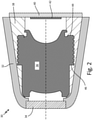
- FIG. 2 is a schematic cross-sectional view of optical assembly 30.
- Optical assembly 30 is a substantially cylindrical structure that supports an optical lens stack.
- Optical assembly 30 includes housing 32, window 34, optical lens stack 36, internal mounting structure 38, electronic package 40, and focal plane array 42. Stops 44 and 46 minimize setback and setforward motion respectively during a launch event.
- optical wavelengths of interest for optical assembly 30 range from infrared to visible.
- Cylindrical lens stack 36 includes metal inner ring 50, metal outer ring 52, lenses L1-L5 and spacers S1-S4. Retaining ring 54 secures the lens stack after assembly.
- lens stack 36 shown in FIG. 3 is only one of a number of possible embodiments that may be utilized for optical sensing applications in the art of seeker optics.
- Cavity 60 between inner ring 50 and outer ring 52 may be filled with an energy absorbing material such as rubber, flexible Kevlar composites, Kevlar doped elastomers or other rubber-like material through holes 58.
- Outer ring 52 and filled cavity 60 provide an opto-mechanical isolator structure that dampens and mitigates shock and vibration.
- the isolator may be designed such that it includes stops 44 and 46 to limit setback and setforward travel.
- the natural frequency of the isolator may be designed to attenuate particular frequencies that could cause damage in the optical stack.
- the filler of cavity 60 is a thermal barrier that decreases the amount of heat transferred by thermal conduction through the housing into the lens stack in an operation such as a gun launch.
- the outside diameter of inner ring 50 and the inside diameter of outer ring 52 may have circumferential and axial grooves that result in barriers to setback, setforward, and rotation during operation.
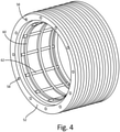
- a perspective view of outer ring 52 showing the cast rubber liner is shown in FIG. 4 .
- Circumferential barriers 60 to setback and setforward motion are formed by circumferential grooves in the outer diameter of ring 50 and the inner diameter of ring 52.
- Axial barriers 62 to rotational motion result from axial grooves in the outer diameter of ring 50 and the inner diameter of ring 52.
- FIG. 5 is a flow diagram of a method of forming the vibration isolated optical lens stack 36.
- Method 70 includes forming inner ring 50 of the mounting structure capable of containing a series of axially mounted circular lenses L1-L5 (step 72).
- the lenses may be positioned in inner ring 50 on circumferential mounting surfaces that closely match the outer surfaces of the lenses in the stack.
- a circumferential groove is formed along a fixed axial length on the outer diameter of inner ring 50 (step 74).
- the vibration isolator structure is formed.
- outer ring 52 is formed that closely fits over the outside diameter of inner ring 20 (step 76).
- the outer ring may be threaded for future insertion in a seeker assembly.
- a circumferential groove is formed in the inner diameter of outer ring 52 along the same fixed axial length of the outer ring to form a circumferential cavity 60 (step 78). Circumferential and axial grooves are machined in the inner diameter of outer ring 52 and the outer diameter of inner ring 50 in the channel (step 80).
- outer ring 52 is installed on inner ring 50 to form isolator cavity 60 (step 82).
- the resulting isolator cavity may be filed with a rubber or rubber-like energy absorbing material to form the isolator for damping/mitigating vibration (step 84).
- the opto-mechanical isolator structure includes outer ring 52, cavity 60, and the energy absorbing material.
- the grooves filled with the cast energy absorbing material act to prevent shifting during setback, setfoward and rotation during launch and flight.
- the isolator structure is placed on the lens stack such that the resulting vibration and shock isolation structure is centered on the center of gravity of the system to prevent rocking during launch.
- the lenses are then installed in the inner ring with spacers between each lens such that the outer surfaces of the lenses match their respective circumferential mounting surfaces in inner ring 50 (step 86).
- Final steps of the assembly include securing the optical lens stack in position on a focal plane array and associated electronic assembly behind a protective window (step 90).
- An optical lens stack may include an inner ring of a mounting structure including a plurality of axially spaced circumferential lens mounting surfaces on an inside diameter of the inner ring, wherein an outside diameter of the inner ring is grooved over a fixed axial distance to form a circumferential channel in the outside diameter of the inner ring.
- the lens stack further includes an outer ring formed to fit over the inner ring, wherein an inside diameter of the outer ring is grooved along the same fixed axial distance as the inner ring thereby forming a circumferential cavity between the inside diameter of the outer ring and the outside diameter of the inner ring when the outer ring is mounted on the inner ring.
- the lens stack further includes an energy absorbing conformal filler material that fills the cavity to form a mechanical vibration isolator in the mounting structure of the optical lens stack and a plurality of optical lenses formed to fit the lens mounting surfaces on the inside diameter of the inner ring of the mounting structure.
- the optical lens stack of the preceding paragraph can optionally include, additionally and/or alternatively, any one or more of the following features, configurations and/or additional components:
- the inner and outer rings may be metal.
- the cavity between the inside diameter of the outer ring and the outside diameter of the inner ring may have axial and circumferential grooves that act to prevent the filler material cast in the cavity from rotating or translating during operation.
- the conformal filler material that fills the cavity may be rubber, flexible Kevlar composites, or Kevlar doped elastomers.
- the optical lens may be separated from each other by spacers.
- the top lens in the stack may be secured by a circular retainer attached to the inner ring.
- the energy absorbing conformal filler material may be a thermal insulator.
- the optical lens stack may operate in an optical wavelength range from infrared to visible.
- the cavity and filler material that form the vibration isolator may be centered on a center of gravity of the optical lens stack to minimize rocking during operation.
- a method of forming an optical lens stack includes forming an inner ring with an outer diameter and axially spaced circumferential lens mounting surfaces on an inner diameter and forming a groove on a portion of the outer diameter of the inner ring along a fixed axial length to form a circumferential channel on the outer diameter of the inner ring.
- the method further includes forming an outer ring with an inner diameter sized to fit closely over the inner ring and forming a groove on the inner diameter of the outer ring along the same fixed axial length to form a circumferential channel. Attaching the outer ring to the inner ring such that channels in both coincide to form a cavity and filling the cavity with an energy absorbing material forms a mechanical isolator substructure.
- the method further includes inserting a plurality of circular lenses in the inner rings positioned on the axially spaced circumferential lens mounting surfaces and attaching a retaining ring over the last lens to secure the optical lens stack.
- the method of the preceding paragraph can optionally include, additionally and/or alternatively, any one or more of the following features, configurations and/or additional components:
- the inner ring and outer ring may be metal.
- the cavity between the inside diameter of the outer ring and outside diameter of the inner ring may contain axial and circumferential grooves that act to restrain the filler material in the cavity from rotating or translating.
- the outer ring may contain holes that allow filler material to be injected into the cavity.
- the isolator cavity may be placed in the lens stack such that the vibration isolator is centered on a center of gravity of the structure.
- the energy absorbing filler material may be a thermal insulator.
- Each lens in the stack may be separated by spacers.
- a vibration isolator for a cylindrical optical lens stack may include an inner ring of a mounting structure for the optical lens stack wherein an outside diameter of the inner ring is grooved over a fixed axial distance to form a circumferential channel on the outside diameter of the inner ring.
- the isolator structure further includes an outer ring formed to fit over the inner ring wherein an inside diameter of the outer ring is grooved over the same fixed axial distance as the inner ring thereby forming a circumferential cavity between the inside diameter of the outer ring and outside diameter of the inner ring.
- An energy absorbing conformal filler material may fill the cavity to form a mechanical vibration isolator for the lens stack.
- the vibration isolator of the preceding paragraph can optionally include, additionally and/or alternatively, any one or more of the following features, configurations and/or additional components:
- the inner and outer rings may be metal.
- the cavity between the inside diameter of the outer ring and the outside diameter of the inner ring may have axial and circumferential grooves that act to prevent the filler material cast in the cavity from rotating or translating during operation.
- the energy absorbing conformal filler material may be a thermal insulator.
Landscapes
- Physics & Mathematics (AREA)
- Engineering & Computer Science (AREA)
- General Physics & Mathematics (AREA)
- Optics & Photonics (AREA)
- General Engineering & Computer Science (AREA)
- Mechanical Engineering (AREA)
- Health & Medical Sciences (AREA)
- Multimedia (AREA)
- Signal Processing (AREA)
- Aviation & Aerospace Engineering (AREA)
- Acoustics & Sound (AREA)
- Life Sciences & Earth Sciences (AREA)
- Atmospheric Sciences (AREA)
- Toxicology (AREA)
- Environmental & Geological Engineering (AREA)
- Epidemiology (AREA)
- Public Health (AREA)
- Vibration Prevention Devices (AREA)
- Lens Barrels (AREA)
Claims (14)
- Optischer Linsenstapel (36) zur Verwendung in Luftfahrzeugen und Munition, wobei der optische Linsenstapel umfasst:einen Innenring (50) einer Befestigungsstruktur (38), die eine Vielzahl von axial beabstandeten, umlaufenden Linsenbefestigungsoberflächen an einem Innendurchmesser des Innenrings (50) aufweist, wobei ein Außendurchmesser des Innenrings (50) über einen festen axialen Abstand gerillt ist, um einen umlaufenden Kanal in dem Außendurchmesser des Innenrings (50) zu bilden;einen Außenring (52), der so geformt ist, dass er über den Innenring (50) passt, wobei ein Innendurchmesser des Außenrings (52) entlang des gleichen festen axialen Abstands wie der Innenring (50) gerillt ist, wodurch ein umlaufender Hohlraum (60) zwischen dem Innendurchmesser des Außenrings (52) und dem Außendurchmesser des Innenrings (50) gebildet wird, wenn der Außenring (52) auf dem Innenring (50) montiert ist;ein energieabsorbierendes konformes Füllmaterial, das den Hohlraum (60) ausfüllt, um einen mechanischen Schwingungsisolator in der Befestigungsstruktur des optischen Linsenstapels (36) zu bilden;eine Vielzahl optischer Linsen (L1-L5), die so geformt sind, dass sie auf die Linsenbefestigungsoberflächen am Innendurchmesser des Innenrings (50) der Befestigungsstruktur (38) passenwobei sowohl auf dem Außendurchmesser des Innenrings (50) als auch auf dem Innendurchmesser des Außenrings (52) Umfangs- und Axialrillen ausgebildet sind, die während des Betriebs als Barrieren (62) für Rückwärts-, Vorwärts- und Drehbewegungen wirken.
- Optischer Linsenstapel nach Anspruch 1, wobei das konforme Füllmaterial, das den Hohlraum (60) füllt, Gummi, flexiblen Kevlar-Verbundstoffe oder mit Kevlar angereicherte Elastomere ist.
- Optischer Linsenstapel (36) nach Anspruch 1 oder 2, wobei die optischen Linsen durch Abstandshalter (S1-S4) voneinander getrennt sind.
- Optischer Linsenstapel (36) nach Anspruch 1, 2 oder 3, wobei die oberste Linse des Stapels (36) durch eine kreisförmige Halterung (54) gesichert ist, die am Innenring (50) befestigt ist.
- Optischer Linsenstapel (36) nach einem der vorstehenden Ansprüche, wobei der optische Linsenstapel (36) in einem optischen Wellenlängenbereich von infrarot bis sichtbar arbeitet.
- Optischer Linsenstapel (36) nach einem der vorstehenden Ansprüche, wobei der Hohlraum (60) und das Füllmaterial, die den Schwingungsisolator bilden, auf einen Schwerpunkt des optischen Linsenstapels zentriert sind, um ein Wackeln während des Betriebs zu minimieren.
- Verfahren zur Herstellung eines optischen Linsenstapels (36) zur Verwendung in Luftfahrzeugen und Munition, der optische Linsenstapel, wobei das Verfahren Folgendes umfasst:Ausbilden eines Innenrings mit einem Außendurchmesser und axial beabstandeten, umlaufenden Linsenbefestigungsoberflächen an einem Innendurchmesser;Ausbilden einer Rille auf einem Teil des Außendurchmessers des Innenrings entlang einer festen axialen Länge, um einen umlaufenden Kanal auf dem Außendurchmesser des Innenrings zu bilden;Ausbilden eines Außenrings mit einem Innendurchmesser, der so bemessen ist, dass er eng über den Innenring passt;Ausbilden einer Rille auf dem Innendurchmesser des Außenrings entlang der gleichen festen axialen Länge, um einen umlaufenden Kanal zu bilden;Ausbilden von Umfangs- und Axialrillen (62) sowohl am Außendurchmesser des Innenrings als auch am Innendurchmesser des Außenrings, die während des Betriebs als Barrieren für Rückwärts-, Vorwärts- und Drehbewegungen wirkenAnbringen des Außenrings am Innenring, so dass die Kanäle in beiden zusammenkommen, um einen Hohlraum (60) zu bilden;Füllen des Hohlraums (60) mit einem energieabsorbierenden Material, um eine mechanische Isolator-Unterstruktur zu bilden;Einsetzen einer Vielzahl von kreisförmigen Linsen in den Innenring, die auf den axial beabstandeten, umlaufenden Linsenbefestigungsoberflächen angeordnet sind;Anbringen eines Halterings über der letzten Linse, um den optischen Linsenstapel zu sichern.
- Verfahren nach Anspruch 7, wobei der Hohlraum zwischen dem Innendurchmesser des Außenrings und dem Außendurchmesser des Innenrings axiale und umlaufende Rillen aufweist, die dazu dienen, das Füllmaterial im Hohlraum (60) an einer Drehung oder Verschiebung zu hindern.
- Verfahren nach Anspruch 7 oder 8, wobei der Außenring Löcher enthält, durch die Füllmaterial in den Hohlraum (60) eingespritzt werden kann.
- Verfahren nach Anspruch 7, 8 oder 9, wobei der Isolatorhohlraum in dem Linsenstapel so angeordnet ist, dass der Schwingungsisolator in der Mitte des Schwerpunkts der Struktur liegt.
- Verfahren nach einem der Ansprüche 7 bis 10, wobei jede Linse (L1-L5) durch Abstandshalter getrennt ist.
- Optischer Linsenstapel (36) nach einem der Ansprüche 1 bis 6 oder Verfahren nach einem der Ansprüche 7 bis 11, wobei der Innen- und der Außenring (50, 52) Metall sind.
- Optischer Linsenstapel (36) nach einem der Ansprüche 1 bis 6 oder 11 oder 12, wobei der Hohlraum (60) zwischen dem Innendurchmesser des Außenrings und dem Außendurchmesser des Innenrings axiale und umlaufende Rillen aufweist, die dazu dienen, das in den Hohlraum (60) gegossene Füllmaterial an einer Drehung oder Verschiebung während des Betriebs zu hindern.
- Optischer Linsenstapel (36) nach einem der Ansprüche 1 bis 6 oder 11 bis 13 oder Verfahren nach einem der Ansprüche 7 bis 11, wobei das energieabsorbierende konforme Füllmaterial ein Wärmeisolator ist.
Applications Claiming Priority (1)
| Application Number | Priority Date | Filing Date | Title |
|---|---|---|---|
| US15/709,879 US10443676B2 (en) | 2017-09-20 | 2017-09-20 | Isolated seeker optics |
Publications (2)
| Publication Number | Publication Date |
|---|---|
| EP3460554A1 EP3460554A1 (de) | 2019-03-27 |
| EP3460554B1 true EP3460554B1 (de) | 2022-03-16 |
Family
ID=63642832
Family Applications (1)
| Application Number | Title | Priority Date | Filing Date |
|---|---|---|---|
| EP18195430.6A Active EP3460554B1 (de) | 2017-09-20 | 2018-09-19 | Isolierte sucheroptik |
Country Status (2)
| Country | Link |
|---|---|
| US (1) | US10443676B2 (de) |
| EP (1) | EP3460554B1 (de) |
Families Citing this family (2)
| Publication number | Priority date | Publication date | Assignee | Title |
|---|---|---|---|---|
| CN111190258A (zh) * | 2018-11-15 | 2020-05-22 | 三营超精密光电(晋城)有限公司 | 光学镜头、应用该光学镜头的镜头模组及电子装置 |
| US12554180B2 (en) * | 2022-10-13 | 2026-02-17 | Gopro, Inc. | Optical module isolation in image capture devices |
Family Cites Families (15)
| Publication number | Priority date | Publication date | Assignee | Title |
|---|---|---|---|---|
| DE3843838A1 (de) | 1988-12-24 | 1990-06-28 | Arnold & Richter Kg | Schallgedaempftes wechselobjektiv |
| US5485053A (en) | 1993-10-15 | 1996-01-16 | Univ America Catholic | Method and device for active constrained layer damping for vibration and sound control |
| JPH08152661A (ja) | 1994-11-30 | 1996-06-11 | Canon Inc | 防振装置 |
| DE10062786A1 (de) | 2000-12-15 | 2002-06-20 | Zeiss Carl | System zur Dämpfung von Schwingungen |
| US7002139B2 (en) | 2003-04-23 | 2006-02-21 | Raytheon Company | Window mounting for optical sensor |
| US7145124B2 (en) | 2004-09-15 | 2006-12-05 | Raytheon Company | Multispectral imaging chip using photonic crystals |
| US7767944B2 (en) | 2007-03-07 | 2010-08-03 | Raytheon Company | Piezoelectric fiber, active damped, composite electronic housings |
| KR20100101675A (ko) | 2008-01-23 | 2010-09-17 | 후지필름 가부시키가이샤 | 렌즈 디바이스 |
| KR101141011B1 (ko) * | 2010-05-18 | 2012-05-02 | 삼성전기주식회사 | 카메라모듈 |
| KR101300341B1 (ko) * | 2011-12-05 | 2013-08-28 | 삼성전기주식회사 | 카메라 모듈 |
| US8567969B2 (en) | 2012-02-10 | 2013-10-29 | Raytheon Company | Bi-polymer infrared optics for high-G applications |
| CN104755978B (zh) | 2012-08-10 | 2018-01-12 | 南昌欧菲光电技术有限公司 | 具有柔性印刷电路延伸的自动聚焦相机模组 |
| CN204154187U (zh) | 2014-07-10 | 2015-02-11 | 北京剑邦科技有限公司 | 一种车外瞄准装置 |
| US10845466B2 (en) * | 2016-12-23 | 2020-11-24 | Cepton Technologies, Inc. | Mounting apparatuses for optical components in a scanning lidar system |
| US10451892B2 (en) * | 2017-09-20 | 2019-10-22 | Rosemount Aerospace Inc. | Active isolation for seeker optics |
-
2017
- 2017-09-20 US US15/709,879 patent/US10443676B2/en active Active
-
2018
- 2018-09-19 EP EP18195430.6A patent/EP3460554B1/de active Active
Also Published As
| Publication number | Publication date |
|---|---|
| EP3460554A1 (de) | 2019-03-27 |
| US20190085931A1 (en) | 2019-03-21 |
| US10443676B2 (en) | 2019-10-15 |
Similar Documents
| Publication | Publication Date | Title |
|---|---|---|
| US8430578B1 (en) | Separation of main and secondary inertial measurements for improved line of sight error of an imaging vehicle's isolated detector assembly | |
| US11754380B2 (en) | Drone payload—energetic weapons pod | |
| US9500454B1 (en) | Mortar projectile with guided deceleration system for delivering a payload | |
| US10443676B2 (en) | Isolated seeker optics | |
| US8234979B1 (en) | 3D shock isolation apparatus with access to one end of a body | |
| US20120298088A1 (en) | System and method for delivering a projectile toward a target | |
| US6244535B1 (en) | Man-packable missile weapon system | |
| US8567969B2 (en) | Bi-polymer infrared optics for high-G applications | |
| EP0447080A1 (de) | Aufklärungsvorrichtung | |
| US20050115440A1 (en) | Granular matter filled weapon guidance electronics unit | |
| US10656369B2 (en) | Mounting of optical elements for imaging in air vehicles | |
| EP1209075B1 (de) | Optische Fensteranordnung für Ultraschall-Plattform | |
| EP3220177B1 (de) | Halterung für optische komponente für high-g-anwendungen | |
| US4227438A (en) | Weapon system, notably infantry anti-tank weapon | |
| US8640619B1 (en) | Use of polyamide thermal plastics as low cost electronics potting compounds for munitions applications | |
| KR101262696B1 (ko) | 유도탄의 보호덮개, 이를 구비하는 유도탄 및 유도탄의 충격완화방법 | |
| EP3467426A1 (de) | Aktive isolierung für sucheroptik | |
| KR20120058335A (ko) | 쉘 조립체, 이를 구비하는 유도탄 및 유도탄의 충격완화방법 | |
| RU2577745C1 (ru) | Переносной тактический комплекс | |
| CN108981473A (zh) | 一种对旋翼无人机的拦截方法 | |
| KR102038577B1 (ko) | 충격 완화 구조를 포함하는 신관 조립체 | |
| US12267974B2 (en) | Electronics unit | |
| US12535308B1 (en) | Recovery system for high performance large bore projectiles | |
| US12560415B2 (en) | Integrally formed high-G shock metal isolator in a projectile | |
| KR102116059B1 (ko) | 이종 재료를 포함하는 유도탄의 구동부 기체 |
Legal Events
| Date | Code | Title | Description |
|---|---|---|---|
| PUAI | Public reference made under article 153(3) epc to a published international application that has entered the european phase |
Free format text: ORIGINAL CODE: 0009012 |
|
| STAA | Information on the status of an ep patent application or granted ep patent |
Free format text: STATUS: THE APPLICATION HAS BEEN PUBLISHED |
|
| AK | Designated contracting states |
Kind code of ref document: A1 Designated state(s): AL AT BE BG CH CY CZ DE DK EE ES FI FR GB GR HR HU IE IS IT LI LT LU LV MC MK MT NL NO PL PT RO RS SE SI SK SM TR |
|
| AX | Request for extension of the european patent |
Extension state: BA ME |
|
| STAA | Information on the status of an ep patent application or granted ep patent |
Free format text: STATUS: REQUEST FOR EXAMINATION WAS MADE |
|
| 17P | Request for examination filed |
Effective date: 20190919 |
|
| RBV | Designated contracting states (corrected) |
Designated state(s): AL AT BE BG CH CY CZ DE DK EE ES FI FR GB GR HR HU IE IS IT LI LT LU LV MC MK MT NL NO PL PT RO RS SE SI SK SM TR |
|
| GRAP | Despatch of communication of intention to grant a patent |
Free format text: ORIGINAL CODE: EPIDOSNIGR1 |
|
| STAA | Information on the status of an ep patent application or granted ep patent |
Free format text: STATUS: GRANT OF PATENT IS INTENDED |
|
| INTG | Intention to grant announced |
Effective date: 20210930 |
|
| GRAS | Grant fee paid |
Free format text: ORIGINAL CODE: EPIDOSNIGR3 |
|
| GRAA | (expected) grant |
Free format text: ORIGINAL CODE: 0009210 |
|
| STAA | Information on the status of an ep patent application or granted ep patent |
Free format text: STATUS: THE PATENT HAS BEEN GRANTED |
|
| AK | Designated contracting states |
Kind code of ref document: B1 Designated state(s): AL AT BE BG CH CY CZ DE DK EE ES FI FR GB GR HR HU IE IS IT LI LT LU LV MC MK MT NL NO PL PT RO RS SE SI SK SM TR |
|
| REG | Reference to a national code |
Ref country code: GB Ref legal event code: FG4D |
|
| REG | Reference to a national code |
Ref country code: CH Ref legal event code: EP Ref country code: DE Ref legal event code: R096 Ref document number: 602018032243 Country of ref document: DE |
|
| REG | Reference to a national code |
Ref country code: IE Ref legal event code: FG4D |
|
| REG | Reference to a national code |
Ref country code: AT Ref legal event code: REF Ref document number: 1476305 Country of ref document: AT Kind code of ref document: T Effective date: 20220415 |
|
| REG | Reference to a national code |
Ref country code: LT Ref legal event code: MG9D |
|
| REG | Reference to a national code |
Ref country code: NL Ref legal event code: MP Effective date: 20220316 |
|
| PG25 | Lapsed in a contracting state [announced via postgrant information from national office to epo] |
Ref country code: SE Free format text: LAPSE BECAUSE OF FAILURE TO SUBMIT A TRANSLATION OF THE DESCRIPTION OR TO PAY THE FEE WITHIN THE PRESCRIBED TIME-LIMIT Effective date: 20220316 Ref country code: RS Free format text: LAPSE BECAUSE OF FAILURE TO SUBMIT A TRANSLATION OF THE DESCRIPTION OR TO PAY THE FEE WITHIN THE PRESCRIBED TIME-LIMIT Effective date: 20220316 Ref country code: NO Free format text: LAPSE BECAUSE OF FAILURE TO SUBMIT A TRANSLATION OF THE DESCRIPTION OR TO PAY THE FEE WITHIN THE PRESCRIBED TIME-LIMIT Effective date: 20220616 Ref country code: LT Free format text: LAPSE BECAUSE OF FAILURE TO SUBMIT A TRANSLATION OF THE DESCRIPTION OR TO PAY THE FEE WITHIN THE PRESCRIBED TIME-LIMIT Effective date: 20220316 Ref country code: HR Free format text: LAPSE BECAUSE OF FAILURE TO SUBMIT A TRANSLATION OF THE DESCRIPTION OR TO PAY THE FEE WITHIN THE PRESCRIBED TIME-LIMIT Effective date: 20220316 Ref country code: BG Free format text: LAPSE BECAUSE OF FAILURE TO SUBMIT A TRANSLATION OF THE DESCRIPTION OR TO PAY THE FEE WITHIN THE PRESCRIBED TIME-LIMIT Effective date: 20220616 |
|
| REG | Reference to a national code |
Ref country code: AT Ref legal event code: MK05 Ref document number: 1476305 Country of ref document: AT Kind code of ref document: T Effective date: 20220316 |
|
| PG25 | Lapsed in a contracting state [announced via postgrant information from national office to epo] |
Ref country code: LV Free format text: LAPSE BECAUSE OF FAILURE TO SUBMIT A TRANSLATION OF THE DESCRIPTION OR TO PAY THE FEE WITHIN THE PRESCRIBED TIME-LIMIT Effective date: 20220316 Ref country code: GR Free format text: LAPSE BECAUSE OF FAILURE TO SUBMIT A TRANSLATION OF THE DESCRIPTION OR TO PAY THE FEE WITHIN THE PRESCRIBED TIME-LIMIT Effective date: 20220617 Ref country code: FI Free format text: LAPSE BECAUSE OF FAILURE TO SUBMIT A TRANSLATION OF THE DESCRIPTION OR TO PAY THE FEE WITHIN THE PRESCRIBED TIME-LIMIT Effective date: 20220316 |
|
| PG25 | Lapsed in a contracting state [announced via postgrant information from national office to epo] |
Ref country code: NL Free format text: LAPSE BECAUSE OF FAILURE TO SUBMIT A TRANSLATION OF THE DESCRIPTION OR TO PAY THE FEE WITHIN THE PRESCRIBED TIME-LIMIT Effective date: 20220316 |
|
| PG25 | Lapsed in a contracting state [announced via postgrant information from national office to epo] |
Ref country code: SM Free format text: LAPSE BECAUSE OF FAILURE TO SUBMIT A TRANSLATION OF THE DESCRIPTION OR TO PAY THE FEE WITHIN THE PRESCRIBED TIME-LIMIT Effective date: 20220316 Ref country code: SK Free format text: LAPSE BECAUSE OF FAILURE TO SUBMIT A TRANSLATION OF THE DESCRIPTION OR TO PAY THE FEE WITHIN THE PRESCRIBED TIME-LIMIT Effective date: 20220316 Ref country code: RO Free format text: LAPSE BECAUSE OF FAILURE TO SUBMIT A TRANSLATION OF THE DESCRIPTION OR TO PAY THE FEE WITHIN THE PRESCRIBED TIME-LIMIT Effective date: 20220316 Ref country code: PT Free format text: LAPSE BECAUSE OF FAILURE TO SUBMIT A TRANSLATION OF THE DESCRIPTION OR TO PAY THE FEE WITHIN THE PRESCRIBED TIME-LIMIT Effective date: 20220718 Ref country code: ES Free format text: LAPSE BECAUSE OF FAILURE TO SUBMIT A TRANSLATION OF THE DESCRIPTION OR TO PAY THE FEE WITHIN THE PRESCRIBED TIME-LIMIT Effective date: 20220316 Ref country code: EE Free format text: LAPSE BECAUSE OF FAILURE TO SUBMIT A TRANSLATION OF THE DESCRIPTION OR TO PAY THE FEE WITHIN THE PRESCRIBED TIME-LIMIT Effective date: 20220316 Ref country code: CZ Free format text: LAPSE BECAUSE OF FAILURE TO SUBMIT A TRANSLATION OF THE DESCRIPTION OR TO PAY THE FEE WITHIN THE PRESCRIBED TIME-LIMIT Effective date: 20220316 Ref country code: AT Free format text: LAPSE BECAUSE OF FAILURE TO SUBMIT A TRANSLATION OF THE DESCRIPTION OR TO PAY THE FEE WITHIN THE PRESCRIBED TIME-LIMIT Effective date: 20220316 |
|
| PG25 | Lapsed in a contracting state [announced via postgrant information from national office to epo] |
Ref country code: PL Free format text: LAPSE BECAUSE OF FAILURE TO SUBMIT A TRANSLATION OF THE DESCRIPTION OR TO PAY THE FEE WITHIN THE PRESCRIBED TIME-LIMIT Effective date: 20220316 Ref country code: IS Free format text: LAPSE BECAUSE OF FAILURE TO SUBMIT A TRANSLATION OF THE DESCRIPTION OR TO PAY THE FEE WITHIN THE PRESCRIBED TIME-LIMIT Effective date: 20220716 Ref country code: AL Free format text: LAPSE BECAUSE OF FAILURE TO SUBMIT A TRANSLATION OF THE DESCRIPTION OR TO PAY THE FEE WITHIN THE PRESCRIBED TIME-LIMIT Effective date: 20220316 |
|
| REG | Reference to a national code |
Ref country code: DE Ref legal event code: R097 Ref document number: 602018032243 Country of ref document: DE |
|
| PLBE | No opposition filed within time limit |
Free format text: ORIGINAL CODE: 0009261 |
|
| STAA | Information on the status of an ep patent application or granted ep patent |
Free format text: STATUS: NO OPPOSITION FILED WITHIN TIME LIMIT |
|
| PG25 | Lapsed in a contracting state [announced via postgrant information from national office to epo] |
Ref country code: DK Free format text: LAPSE BECAUSE OF FAILURE TO SUBMIT A TRANSLATION OF THE DESCRIPTION OR TO PAY THE FEE WITHIN THE PRESCRIBED TIME-LIMIT Effective date: 20220316 |
|
| 26N | No opposition filed |
Effective date: 20221219 |
|
| PG25 | Lapsed in a contracting state [announced via postgrant information from national office to epo] |
Ref country code: SI Free format text: LAPSE BECAUSE OF FAILURE TO SUBMIT A TRANSLATION OF THE DESCRIPTION OR TO PAY THE FEE WITHIN THE PRESCRIBED TIME-LIMIT Effective date: 20220316 |
|
| PG25 | Lapsed in a contracting state [announced via postgrant information from national office to epo] |
Ref country code: MC Free format text: LAPSE BECAUSE OF FAILURE TO SUBMIT A TRANSLATION OF THE DESCRIPTION OR TO PAY THE FEE WITHIN THE PRESCRIBED TIME-LIMIT Effective date: 20220316 |
|
| REG | Reference to a national code |
Ref country code: CH Ref legal event code: PL |
|
| REG | Reference to a national code |
Ref country code: BE Ref legal event code: MM Effective date: 20220930 |
|
| PG25 | Lapsed in a contracting state [announced via postgrant information from national office to epo] |
Ref country code: LU Free format text: LAPSE BECAUSE OF NON-PAYMENT OF DUE FEES Effective date: 20220919 |
|
| PG25 | Lapsed in a contracting state [announced via postgrant information from national office to epo] |
Ref country code: LI Free format text: LAPSE BECAUSE OF NON-PAYMENT OF DUE FEES Effective date: 20220930 Ref country code: IT Free format text: LAPSE BECAUSE OF FAILURE TO SUBMIT A TRANSLATION OF THE DESCRIPTION OR TO PAY THE FEE WITHIN THE PRESCRIBED TIME-LIMIT Effective date: 20220316 Ref country code: IE Free format text: LAPSE BECAUSE OF NON-PAYMENT OF DUE FEES Effective date: 20220919 Ref country code: CH Free format text: LAPSE BECAUSE OF NON-PAYMENT OF DUE FEES Effective date: 20220930 |
|
| PG25 | Lapsed in a contracting state [announced via postgrant information from national office to epo] |
Ref country code: BE Free format text: LAPSE BECAUSE OF NON-PAYMENT OF DUE FEES Effective date: 20220930 |
|
| PG25 | Lapsed in a contracting state [announced via postgrant information from national office to epo] |
Ref country code: HU Free format text: LAPSE BECAUSE OF FAILURE TO SUBMIT A TRANSLATION OF THE DESCRIPTION OR TO PAY THE FEE WITHIN THE PRESCRIBED TIME-LIMIT; INVALID AB INITIO Effective date: 20180919 |
|
| PG25 | Lapsed in a contracting state [announced via postgrant information from national office to epo] |
Ref country code: CY Free format text: LAPSE BECAUSE OF FAILURE TO SUBMIT A TRANSLATION OF THE DESCRIPTION OR TO PAY THE FEE WITHIN THE PRESCRIBED TIME-LIMIT Effective date: 20220316 |
|
| PG25 | Lapsed in a contracting state [announced via postgrant information from national office to epo] |
Ref country code: MK Free format text: LAPSE BECAUSE OF FAILURE TO SUBMIT A TRANSLATION OF THE DESCRIPTION OR TO PAY THE FEE WITHIN THE PRESCRIBED TIME-LIMIT Effective date: 20220316 |
|
| PG25 | Lapsed in a contracting state [announced via postgrant information from national office to epo] |
Ref country code: TR Free format text: LAPSE BECAUSE OF FAILURE TO SUBMIT A TRANSLATION OF THE DESCRIPTION OR TO PAY THE FEE WITHIN THE PRESCRIBED TIME-LIMIT Effective date: 20220316 |
|
| PG25 | Lapsed in a contracting state [announced via postgrant information from national office to epo] |
Ref country code: MT Free format text: LAPSE BECAUSE OF FAILURE TO SUBMIT A TRANSLATION OF THE DESCRIPTION OR TO PAY THE FEE WITHIN THE PRESCRIBED TIME-LIMIT Effective date: 20220316 |
|
| PGFP | Annual fee paid to national office [announced via postgrant information from national office to epo] |
Ref country code: DE Payment date: 20250820 Year of fee payment: 8 |
|
| PGFP | Annual fee paid to national office [announced via postgrant information from national office to epo] |
Ref country code: GB Payment date: 20250822 Year of fee payment: 8 |
|
| PGFP | Annual fee paid to national office [announced via postgrant information from national office to epo] |
Ref country code: FR Payment date: 20250820 Year of fee payment: 8 |
|
| P01 | Opt-out of the competence of the unified patent court (upc) registered |
Free format text: CASE NUMBER: UPC_APP_0017877_3460554/2025 Effective date: 20251217 |