EP3460552B1 - Hinter der wand angeordnetes faserspulmodul - Google Patents
Hinter der wand angeordnetes faserspulmodul Download PDFInfo
- Publication number
- EP3460552B1 EP3460552B1 EP18194241.8A EP18194241A EP3460552B1 EP 3460552 B1 EP3460552 B1 EP 3460552B1 EP 18194241 A EP18194241 A EP 18194241A EP 3460552 B1 EP3460552 B1 EP 3460552B1
- Authority
- EP
- European Patent Office
- Prior art keywords
- spool
- plate
- hub
- module
- cover
- Prior art date
- Legal status (The legal status is an assumption and is not a legal conclusion. Google has not performed a legal analysis and makes no representation as to the accuracy of the status listed.)
- Active
Links
Images


Classifications
-
- G—PHYSICS
- G02—OPTICS
- G02B—OPTICAL ELEMENTS, SYSTEMS OR APPARATUS
- G02B6/00—Light guides; Structural details of arrangements comprising light guides and other optical elements, e.g. couplings
- G02B6/46—Processes or apparatus adapted for installing or repairing optical fibres or optical cables
- G02B6/47—Installation in buildings
- G02B6/475—Mechanical aspects of installing cables in ducts or the like for buildings
-
- G—PHYSICS
- G02—OPTICS
- G02B—OPTICAL ELEMENTS, SYSTEMS OR APPARATUS
- G02B6/00—Light guides; Structural details of arrangements comprising light guides and other optical elements, e.g. couplings
- G02B6/44—Mechanical structures for providing tensile strength and external protection for fibres, e.g. optical transmission cables
- G02B6/4439—Auxiliary devices
- G02B6/444—Systems or boxes with surplus lengths
- G02B6/4453—Cassettes
-
- G—PHYSICS
- G02—OPTICS
- G02B—OPTICAL ELEMENTS, SYSTEMS OR APPARATUS
- G02B6/00—Light guides; Structural details of arrangements comprising light guides and other optical elements, e.g. couplings
- G02B6/44—Mechanical structures for providing tensile strength and external protection for fibres, e.g. optical transmission cables
- G02B6/4439—Auxiliary devices
- G02B6/4457—Bobbins; Reels
-
- G—PHYSICS
- G02—OPTICS
- G02B—OPTICAL ELEMENTS, SYSTEMS OR APPARATUS
- G02B6/00—Light guides; Structural details of arrangements comprising light guides and other optical elements, e.g. couplings
- G02B6/46—Processes or apparatus adapted for installing or repairing optical fibres or optical cables
- G02B6/47—Installation in buildings
- G02B6/477—Wall sockets
-
- H—ELECTRICITY
- H01—ELECTRIC ELEMENTS
- H01R—ELECTRICALLY-CONDUCTIVE CONNECTIONS; STRUCTURAL ASSOCIATIONS OF A PLURALITY OF MUTUALLY-INSULATED ELECTRICAL CONNECTING ELEMENTS; COUPLING DEVICES; CURRENT COLLECTORS
- H01R13/00—Details of coupling devices of the kinds covered by groups H01R12/70 or H01R24/00 - H01R33/00
- H01R13/73—Means for mounting coupling parts to apparatus or structures, e.g. to a wall
-
- H—ELECTRICITY
- H02—GENERATION; CONVERSION OR DISTRIBUTION OF ELECTRIC POWER
- H02G—INSTALLATION OF ELECTRIC CABLES OR LINES, OR OF COMBINED OPTICAL AND ELECTRIC CABLES OR LINES
- H02G11/00—Arrangements of electric cables or lines between relatively-movable parts
- H02G11/02—Arrangements of electric cables or lines between relatively-movable parts using take-up reel or drum
-
- H—ELECTRICITY
- H02—GENERATION; CONVERSION OR DISTRIBUTION OF ELECTRIC POWER
- H02G—INSTALLATION OF ELECTRIC CABLES OR LINES, OR OF COMBINED OPTICAL AND ELECTRIC CABLES OR LINES
- H02G3/00—Installations of electric cables or lines or protective tubing therefor in or on buildings, equivalent structures or vehicles
- H02G3/02—Details
- H02G3/08—Distribution boxes; Connection or junction boxes
- H02G3/12—Distribution boxes; Connection or junction boxes for flush mounting
-
- G—PHYSICS
- G02—OPTICS
- G02B—OPTICAL ELEMENTS, SYSTEMS OR APPARATUS
- G02B6/00—Light guides; Structural details of arrangements comprising light guides and other optical elements, e.g. couplings
- G02B6/46—Processes or apparatus adapted for installing or repairing optical fibres or optical cables
- G02B6/50—Underground or underwater installation; Installation through tubing, conduits or ducts
-
- H—ELECTRICITY
- H02—GENERATION; CONVERSION OR DISTRIBUTION OF ELECTRIC POWER
- H02G—INSTALLATION OF ELECTRIC CABLES OR LINES, OR OF COMBINED OPTICAL AND ELECTRIC CABLES OR LINES
- H02G3/00—Installations of electric cables or lines or protective tubing therefor in or on buildings, equivalent structures or vehicles
- H02G3/02—Details
- H02G3/08—Distribution boxes; Connection or junction boxes
- H02G3/14—Fastening of cover or lid to box
Definitions
- the present invention relates to modules for storing optical fibers inside the premises of fiber optic network users.
- a drop fiber is routed over a path that is hidden as much as possible from view by occupants of the premises.
- the fiber may be stapled or bonded with an adhesive to a crown molding near the ceiling and/or to a baseboard near the floor.
- the path extends between an entry point at the premises where the fiber is connected at one end to a provider network terminal, and at the other end to a module that is mounted on a wall inside the premises. Any remaining or "slack" length of fiber is stored inside the module, and on the same spool from which the fiber was initially supplied and unwound when routed at the premises.
- the end of the of the fiber stored on the spool is terminated in a connector, and the connector is mated to one side of a connector adapter that is also stored inside the module.
- the other side of the adapter is exposed to the outside, and a fiber jumper cable is connected at one end to the adapter.
- the other end of the jumper cable is typically connected to an optical network terminal (ONT) that may be placed on a desk or shelf at the premises.
- ONT optical network terminal
- the ONT operates to convert downlink optical signals originating from the network provider and transmitted from the network terminal through the drop fiber and the jumper cable, into corresponding electrical signals that are provided at an output of the ONT.
- a wire cable is connected at one end to the ONT output, and at the other end to, e.g ,, a television and/or a router that is configured to link other electronic devices at the premises with the fiber optic network.
- the ONT also converts electrical signals that originate from the devices into corresponding uplink optical signals that it sends to the network terminal through the jumper cable and the drop fiber, for transmission to the network provider.
- U.S. Patents No. 6,243,526 (Jun. 5, 2001 ) and No. 5,761,368 (Jun. 2, 1998 ) relate to storage spool assemblies for optical fiber. Slack lengths of optical fibers that are routed behind a wall at user premises, are stored on spools that are fixed behind a faceplate mounted on the front of the wall. The fibers are coupled to connectors that are accessible on the front of the faceplate. The spools are not accessible for storing excess lengths of fibers that are routed along exposed surfaces of walls or wall moldings at the premises, however.
- a fiber storage module for storing a slack length of fiber after the fiber is routed along a wall or other exposed surface at user premises, and for enabling the fiber to be connected to optical devices at the premises, wherein the module is out of the ordinary field of view of occupants at the premises.
- US 5 638 481 A discloses an outlet assembly for use with optical fibers and, where called for, electrical cables has a hinged wall plate adapted to be mounted to an outlet box.
- the wall plate is adapted to receive couplers therein for receiving both optical fiber and electrical connectors.
- a storage spool is mountable to the rear of the wall plate for storing the required amounts of fiber slack and includes wall members and guide members for maintaining separation among at least some of the fibers.
- the wall plate has an upper portion which is pivotally connected to a lower portion and which can be swung away from the outlet box to provide access to the rear of the wall plate.
- a protective hood is movably mountable to the front of the wall plate to protect the various connections thereto.
- US 2015/153513 A1 teaches a fiber optic splicing assembly having an assembly housing and a fiber storing device.
- the assembly housing has a mounting side and an opposite outer facing side.
- the fiber storing device is removably mounted to the assembly housing, and is at least partially received in an assembly receiving passageway of a mounting wall.
- a module for storing a length of optical fiber at user premises according to claim 1 is provided.
- FIG. 1 shows a first embodiment of a fiber spool module 10 according to the invention
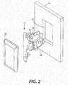
- FIG. 2 shows a second embodiment of a fiber spool module 12 according to the invention.
- Both of the modules 10, 12 are constructed and arranged for installation behind a drywall 14 at the premises of a fiber optic network user, so that the installed modules will have little if any adverse visual impact on occupants of the premises.
- Module 10 is constructed to be housed inside a standard utility box 16 that extends behind the drywall 14.
- the box 16 fits snugly within a rectangular opening 18 that is cut in the drywall 14 and measures, e.g ., 8.89 cm by 5.08 cm (3.50 inches by 2.00 inches).
- the module 12 is dimensioned and arranged to pass through the opening 18 and to extend behind the drywall 14 without the utility box 16.
- the module 10 includes an adapter plate 20, a cover 22, a spool plate 24 that hinges on the adapter plate 24, a spool 26 configured to mount on the spool plate 24, and a connector adapter 27 (e.g ., type SCA) that is supported on the adapter plate 20.
- type SCA connectors are dimensionally the same as SC connectors, but with an angled end face that introduces lower loss when mated with another SCA connector.
- Module 12 includes the cover 22, the spool plate 24, the spool 26, the connector adapter 27, and a different adapter plate 28.
- the adapter plates 20, 28 are oriented for insertion through the opening 18 in the drywall 14, after the plates 20, 28 are assembled with the spool plate 24, the spool 26, the adapter 27, and a length of slack fiber on the spool 26 is terminated, as described below.
- FIG. 3 is an enlarged view of the adapter plate 20.
- the plate 20 is generally elongated and may be formed of a clear ABS/PC blend, or equivalent material that is RoHS compliant.
- the adapter plate 20 has a pair of keyed slots 30, 32 that are formed to receive and capture corresponding tabs 59a, 59b that project from the inside surface of the cover 22 (see FIG. 5B ), so that the cover 22 can be snapped in place over the adapter plate 20 when the plate is secured across the opening 18 in the drywall 14.
- the adapter plate 20 is configured to accept two 40 mm long splice sleeves, and to allow a slack length of fiber (e.g ., 900 ⁇ m O.D.) wound on the spool 26 to exit from a top or bottom edge of the cover 22 when the adapter plate 20 is fastened to the drywall 14, and the cover 22 is fixed over the adapter plate 20 and the opening 18 in the drywall.
- a slack length of fiber e.g ., 900 ⁇ m O.D.
- the adapter plate 20 may have an overall height H of, e.g ., 11.95 cm (4.706 inches), including short tabs 34 that project from the top and the bottom ends of the plate as viewed in FIG. 3 .
- the tabs 34 are seated in corresponding cutouts in the top and the bottom edges of the cover 22 when the cover is fixed over the adapter plate 20.
- a first pair of open ended slots 36 are formed near the top and the bottom ends of the adapter plate 20.
- the slots 36 are spaced apart by, e.g ., 10.24 cm (4.030 inches) so that the adapter plate 20 can be fastened by screws to the drywall 14 above and below the wall opening 18.
- a second pair of open ended slots 38 are also formed along the length of the adapter plate 20, wherein the slots 38 are spaced, e.g ., 8.382 cm (3.300 inches) apart.
- the cover 22 can therefore be fastened directly to the utility box 16 by inserting two screws through openings formed in the cover 22 (see FIG. 5 ), passing the screws through the slots 38 in the adapter plate 20, and threading the screws into corresponding openings formed in the utility box 16.
- An elongated splice holder 40 is formed midway along the length of the adapter plate 20, for receiving and storing two 40 mm splice sleeves.
- the holder 40 is formed by a continuous flat vertical wall 40a that is approximately 3.932 cm (1.548 inches) long and 0.744 cm (0.293 inch) high, and a series of six evenly spaced retaining fingers 40b that are arrayed parallel to the wall 40a and spaced approximately 0.269 cm (0.106 inch) from the wall.
- An adapter mounting frame 42 is also formed midway along the length of the adapter plate 20 and next to the splice holder 40, for securing the connector adapter 27 as shown in FIGS. 1 and 2 .
- the frame 42 is formed, e.g ., by a 1.78 cm (0.699 inch) wall 46 that extends from the base of the plate 20 at an angle of 110 degrees with respect to the base.
- a rectangular aperture 48 is formed in the wall 46 for receiving the adapter 27, wherein the aperture 48 Is dimensioned so that the wall 46 secures the adapter firmly at the desired orientation.
- Two spool plate hinge mounts 44a, 44b are also formed midway along the length of the adapter plate 20, and at either side of the plate. Each one of the mounts 44a, 44b forms an elongated hinge knuckle 50a, 50b, wherein the axis of each knuckle is approximately 0.600 inch above the base of the plate 20.
- FIG. 4 is an enlarged view of the adapter plate 28.
- Parts or features of the adapter plate 28 that are same as corresponding parts of the adapter plate 20 are identified using the same reference numerals with an apostrophe.
- the adapter plate 28 is generally elongated and includes the tabs 34' at the top and the bottom ends of the plate 28.
- a first pair of open ended slots 36' are formed near the top and the bottom ends of the adapter plate 28.
- the slots 36' are spaced apart by, e.g ., 10.24 cm (4.030 inches) so that the adapter plate 28 can be fastened by screws to the drywall 14 above and below wall cutout 18 in FIG. 2 .
- a pair of cylindrical sleeves or bosses 39 are fixed next to the open ended slots 36' in the adapter plate 28.
- the bosses 39 are, e.g ., 1.27 cm (0.500 inch) high and spaced 8.382 cm (3.300 inches) apart on the adapter plate 28. According ly, the cover 22 can be fastened directly to the adapter plate 28 by inserting screws through the two openings in the cover 22 (see FIG. 5 ), and threading the screws into the bosses 39 on the plate 28.
- the bosses 39 also prevent the screws from coming into contact with any fiber in the vicinity of the screws.
- the adapter plate 28 is also configured to accept two 40 mm long splice sleeves, and to allow a slack length of fiber (e.g ., 900 ⁇ m O.D.) wound on the spool 26 to exit from a top or a bottom edge of the cover 22 when the cover is fixed to the adapter plate 28.
- a slack length of fiber e.g ., 900 ⁇ m O.D.
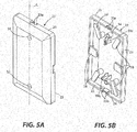
- FIG. 5A is a view of the rectangular cover 22 as seen from the front, and FIG. 5B shows the cover 22 from the rear.
- the cover 22 is also made of a PC/ABS blend or equivalent RoHS compliant material.
- Two vertically aligned openings 50, 52 are formed through the front of the cover 22, wherein the openings 50, 52 are spaced, e.g ., 8.382 cm (3.300 inches) apart from one another.
- the openings 50, 52 will therefore coincide with the slots 38 formed in the adapter plate 20, or with the bosses 39 on the adapter plate 28.
- the cover 22 can therefore be fastened directly to the utility box 16 by aligning the cover openings 50, 52 with the slots 38 in the adapter plate 20 as in FIG. 1 , inserting screws through the openings in the cover and the slots in the adapter plate 20, and threading the screws into the utility box 16.
- the cover 22 can be fastened to the adapter plate 28 by aligning the cover openings 50, 52 with the bosses 39 on the adapter plate 28 as in FIG. 2 , inserting screws through the cover openings, and threading the screws into the bosses 39 on the adapter plate 28.
- Cover 22 has a lip 23 that projects from the rear side about the perimeter of the cover. Cutouts 23a are formed in the lip 23 at the top of the of the cover 22, and cutouts 23b are also formed in the lip at the bottom of the cover. The cutouts 23a, 23b are dimensioned to provide safe clearance for a fiber or jumper cable that is adhered to the outside surface of the drywall 14, to pass to and from the module 10 or 12 after the module is installed behind the drywall 14 and the cover 22 is fastened over the opening 18 in the drywall, as explained below.
- two cylindrical sleeves or bosses 54, 56 are formed on the rear of the cover 22, coaxially with the openings 50, 52.
- the bosses project a sufficient distance from the rear surface of the cover 22 so that they confront either one of the adapter plates 20, 28 when the plate is fastened to the drywall 14 and the cover 22 is placed over the plate as in FIG. 1 or in FIG. 2 .
- the bosses 54, 56 therefore prevent the cover 22 from deforming when screws inserted through the openings 50, 52 are tightened to attach the cover 22 to the utility box 16 as in FIG. 1 , or to the adapter plate 28 as in FIG. 2 .
- the openings 50, 52 in the front of the cover 22 are preferably chamfered, and knockouts are formed at the bottom of each opening.
- the rear of the cover 22 also has a number of retainers 58 arrayed over the rear surface of the cover, for managing and storing a slack length of a fiber jumper cable, after the jumper cable is connected between the module 10 or 12 and an ONT or other optical device at the premises.
- a pair of tabs 59a, 59b also project from the rear of the cover 22, so that the cover can be attached directly to the adapter plate 20 by snapping the tabs 59a, 59b of the cover into the keyed slots 30, 32 in the adapter plate.
- FIG. 6A is view of the spool plate 24 in FIG. 1 , as seen from a front side of the plate 24 on which the spool 26 (see FIGS. 7A & 7B ) is mounted for rotation.
- FIG. 6B shows the spool plate 24 from the opposite side.
- the entire spool 24 can be made, for example, of polypropylene copolymer or an equivalent material that is RoHS compliant.
- the spool plate 24 is formed with a partly circular base 62 having a diameter of, e.g ., 4.237 cm (1.668 inches).
- a first pair of spool retaining fingers 64 and a second pair of spool retaining fingers 66 all rise from the base 62 in an equi-circumferentially spaced array, as seen in FIG. 6A .
- the first pair of retaining fingers 64 reach a height of, e.g ., 1.85 cm (0.727 inch) above the base 62, and the fingers 64 are diametrically opposed to one another.
- the second pair of spool retaining fingers 66 rise to a lower height of, e.g ., 1.67cm (0.659 inch) above the base 62, and the fingers 66 are also diametrically opposite one another.
- Each one of the spool retaining fingers 64 has a lip 64a that projects radially outward from the top of the finger, and each of the retaining fingers 66 also has a radially outwardly projecting lip 66a at the top of the finger.
- the lips 64a and 66a on the retaining fingers cooperate to capture the inner circumference of an annular disk inside the hub of the spool, so that the spool can rotate smoothly about the retaining fingers 64, 66 when the spool hub is centered over the retaining fingers and urged a certain distance toward the base 62 of the spool plate.
- the lips 66a on the shorter pair of retaining fingers 66 clear the inner circumference of the annular disk inside the hub, and the lips 66a diverge radially outward and over the inner circumference of the disk so that the spool 26 is prevented from moving upward on the retaining fingers.
- the base 62 of the spool plate 24 has an array of eight tabs or bosses 68 that rise up from the base in a circular array, coaxially about the retaining fingers 64, 66. As noted below, the bosses 68 will align with and enter a set of corresponding cutouts in the bottom of the spool hub so as to lock the spool 28 from rotation about the retaining fingers.
- the spool plate 24 also has a hinge pin portion 70 appended to the base 62.
- the hinge portion 70 includes two parallel arms 72a, 72b that extend from and are coplanar with the base 62, and a hinge pin 74 supported between the distal ends of the arms 72a, 72b.
- the spool plate 24 can be attached to the adapter plate 20 for swinging movement by urging the hinge pin 74 into either one of the hinge knuckles 50a, 50b of the two hinge mounts 44a, 44b that are formed on the plate 20.
- FIG. 1 the hinge pin portion 70 appended to the base 62.
- the hinge portion 70 includes two parallel arms 72a, 72b that extend from and are coplanar with the base 62, and a hinge pin 74 supported between the distal ends of the arms 72a, 72b.
- the spool plate 24 can also be attached to the adapter plate 28 for swinging movement by urging the hinge pin 74 into either one of the hinge knuckles 50a', 50b' of the two hinge mounts 44a', 44b' formed on the plate 28,
- FIG. 7A is an enlarged view of the spool 26 In FIGS. 1 and 2 .
- FIG. 7B is an enlarged view of a different version of the spool 26, wherein an intermediate set of four flat fiber retaining ears 80 that extend radially outward every 90 degrees from a hollow cylindrical hub 82 of the spool 26 in FIG. 7A , are eliminated.
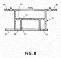
- FIG. 8 is a cross-sectional view of the spool 26 in FIG. 7B in a plane that contains the axis of the spool hub 82
- a first set of four flat fiber retaining ears 84 extend radially outward every 90 degrees from the top axial end of the spool hub 82, and a second set of four flat fiber retaining ears 86 also extend radially outward every 90 degrees from the bottom axial end of the hub 82
- the first and the intermediate sets of retaining ears 84, 80 form a first winding section on an upper portion of the spool hub 82
- the second and the intermediate sets of retaining ears 86, 80 define a second winding section on a lower portion of the hub 82.
- the spool 26 in FIG. 7A can store a length of 900 ⁇ m O.D. buffered fiber in the second winding section on the lower portion of the hub 82, which fiber will be payed out for routing from the module 10 or 12 to a network terminal near an entry point of the premises.
- the same 900 ⁇ m fiber may remain unjacketed, or transition through a length of furcation tubing to a 2.0 mm or 3.0 mm O.D. jacketed fiber, to be stored in the first winding section on the upper portion of the spool 26 In FIG. 7A .
- the fiber in the first winding section will be connected to the ONT or other optical device at the premises without a need for the connector adapter 27.
- a strain relief tab may be added to two of the intermediate retaining ears 80 of the spool 26 to restrain the furcation tubing at the fiber transition point.
- the spool hub 82 also has eight recesses or cutouts 88 formed in the bottom of the hub wall.
- the cutouts 88 are equi-angularly spaced from one another and are dimensioned to align with and receive the eight bosses 68 on the base 62 of the spool plate 24.
- the spool 26 can be locked from rotation about the retaining fingers 64, 66 by lowering the spool hub 82 to a position where the bosses 68 on the base 62 of the spool plate enter the cutouts 88 in the bottom of the hub.
- the spool 26 contains a flat annular support disk 90, the outer circumference of which is joined coaxially to the inner circumference of the spool hub 82, at a position approximately midway between the top and the bottom axial ends of the spool hub 82.
- a cylindrical collar 92 is joined at its upper circumference to the inner circumference of the support disk 90, and a rim 94 projects radially inward from the inner circumference of the support disk 90. The lower circumference of the collar 92 is commensurate with the bottom end of the spool hub 82.
- a rectangular opening of approximately 9.53 cm by 5.72 cm (3.75 inches by 2.25 inches) is cut through the drywall 14 inside the user premises, near an ONT or other optical device to be linked to the user's fiber optic network.
- the size of the hole Is just large enough to accept the spool 26 and, optionally, one SCA to SCA adapter or one 40 mm fiber optic fusion splice sleeve.
- the corresponding adapter plate 20 or 28 is then fastened to the drywall 14 over the rectangular opening using two drywall screws, with the hinge mounts 44a, 44b (or 44a', 44b') on the adapter plate facing away from the drywall.
- the spool 26 is mounted for rotation on the spool plate 24, and the spool plate 24 is fastened to the adapter plate 20 (or 28) by snapping the hinge pin 74 on the spool plate into either the left or the right hinge knuckle 44a, 44b (or 44a', 44b') on the adapter plate, depending on a desired orientation of the spool 26 when the fiber supplied on the spool will be payed out for routing at the premises.
- a first stretch of a continuous length of a buffered optical fiber can be supplied in the second winding section of the spool, and a second stretch of the fiber can be wound in the first winding section of the spool.
- the first stretch of fiber may consist of a length of unjacketed 900 ⁇ m O.D. buffered fiber that will be routed between the module 10 or 12, and a network terminal near an entry point at the premises.
- the second stretch of fiber may remain unjacketed, or have a protective jacket with an O.D. of, e.g., 2.0 or 3.0 mm, wherein the length of the second stretch of fiber is sufficient to extend between the module 10 or 12 and the ONT or other optical device at the premises.
- the spool 26 is ready to be stored behind the drywall 14.
- the spool plate 24 is swung to a position perpendicular to the drywall so that the plate and the mounted spool passes easily through the rectangular opening in the drywall.
- the two screws fastening the adapter plate 20 (or 28) over the rectangular opening in the drywall 14 are loosened and withdrawn, and the adapter plate is reoriented 180 degrees about its long axis. If the spool 26 has the first and second winding sections as in FIG. 7A , enough jacketed fiber is unwound from the first winding section to reach the ONT or other optical device at the premises.
- an SCA or equivalent connector adapter 27 is mounted in the frame 46 on the adapter plate 20 or 28 so that a lower end of the adapter is easily accessible between the spool 26 and the adapter plate for connection to an outside jumper cable.
- the connector adapter 27 is preferably supported in the frame 48 on the adapter plate at an angle of approximately 20 degrees from the vertical, so as to provide the user with easy access to the adapter 27 when removing the cover 22 after the installation.
- the assembled module 10 or 12 is inserted through the rectangular opening 18 in the drywall 14, and the adapter plate is again fastened to the drywall. Once the screws fastening the adapter plate to the drywall are tightened, the cover 22 or a standard utility box blank plate is fastened with screws to the utility box 16 or to the adapter plate 28.
Landscapes
- Physics & Mathematics (AREA)
- Engineering & Computer Science (AREA)
- Civil Engineering (AREA)
- Structural Engineering (AREA)
- General Physics & Mathematics (AREA)
- Optics & Photonics (AREA)
- Architecture (AREA)
- Light Guides In General And Applications Therefor (AREA)
- Mechanical Coupling Of Light Guides (AREA)
Claims (10)
- Ein Modul (10, 12) zum Lagern einer Länge einer optischen Faser auf einem Nutzergelände, das folgende Merkmale aufweist:eine Faserbereitstellungsspule (26), die eine zylindrische Hohlnabe (82), einen ersten Satz von Faserhalteösen (84), die sich von einem oberen axialen Ende der Nabe (82) radial nach außen erstrecken, und einen zweiten Satz von Faserhalteösen (86), die sich von einem unteren axialen Ende der Nabe (82) radial nach außen erstrecken, umfasst, wobei die Sätze von Halteösen (84, 86) zumindest ein Wicklungssegment an der Spule (26) zum Lagern einer Länge einer optischen Faser zum Verlegen auf dem Gelände bilden;eine Spulenplatte (24), die eine im Wesentlichen flache Basis (62) und einen Scharnierstiftabschnitt (70) aufweist, der zwei Arme (72a, 72b), die sich von der Basis (62) aus erstrecken, und einen Scharnierstift (74), der zwischen distalen Enden der Arme (72a, 72b) getragen wird, umfasst; undeine längliche Adapterplatte (20, 28), die dazu ausgebildet und angeordnet ist, eine Gipskartonplatte (14) auf dem Gelände zu befestigen, wobei die Adapterplatte (20, 28) zumindest eine Scharnierhalterung (44a, 44b, 44a', 44b') umfasst, die ein Gelenk (50a, 50b, 50a', 50b') zum Einpassen des Scharnierstifts (74) aufweist, so dass die Spulenplatte (24) und die daran angebrachte Spule (26) zum Zweck einer Schwenkbewegung bezüglich der Adapterplatte (20, 28) befestigt sind;wobei die Spulenplatte (24) und die daran angebrachte Spule (26) auf der Adapterplatte (20, 28) zwischen einer ersten Position, in der eine auf der Spule (26) bereitgestellte optische Faser von der Spule (26) abgewickelt wird, um eine Verlegung über einen gewünschten Pfad auf dem Gelände vorzunehmen, und einer zweiten Position, in der die Spulenplatte (24) und die Spule (26) durch eine Öffnung (18) bestimmter Abmessungen in der Gipskartonplatte (14) auf dem Gelände geführt werden können und die Adapterplatte (20, 28) an der Gipskartonplatte (14) befestigt werden kann, so dass die Spule (26) hinter der Gipskartonplatte (14) gelagert ist, wobei nach dem Verlegen der Faser auf dem Gelände eine Faserlänge auf der Spule (26) verbleibt,dadurch gekennzeichnet, dass eine Anzahl von Spulenhaltefingern (64, 66) sich von der Basis (62) nach oben erstrecken, um die Nabe (82) der Spule (26) in Eingriff zu nehmen, wobei die Spule (26) zur Drehung um die Haltefinger (64, 66) angebracht ist, wenn die Nabe (82) über den Haltefingern (64, 66) zentriert ist und über eine gewisse Strecke zur Basis (62) der Spulenplatte (24) gedrückt wird,wobei die Spule (26) eine ringförmige Tragescheibe (90), deren Außenumfang koaxial an den Innenumfang der Nabe (82) angefügt ist, eine zylindrische Manschette (92), die an ihrem oberen Umfang an den Innenumfang der ringförmigen Tragescheibe (90) angefügt ist, und einen Rand (94), der von dem Innenumfang der ringförmigen Tragescheibe (90) radial nach innen vorsteht, umfasst,wobei die Haltefinger (64, 66) ein erstes und ein zweites Paar von Haltefingern (64, 66) umfassen und die Haltefinger (64, 66) jedes Paares von Haltefingern (64, 66) einander diametral gegenüberliegen,wobei sich das erste Paar von Haltefingern (64) auf eine gewisse Höhe über der Basis (62) der Spulenplatte (24) erhebt, sich das zweite Paar von Haltefingern (66) auf eine Höhe erhebt, die niedriger ist als die des ersten Paares von Haltefingern (64), und jeder der Haltefinger (64, 66) an dem oberen Ende des Haltefingers (64, 66) eine radial nach außen vorstehende Lippe (64a, 66a) aufweist,wobei die Lippen (64a, 66a) zusammenwirken, um den Innenumfang der ringförmigen Tragescheibe (90) in der Nabe (82) zu erfassen, so dass sich die Spule (26) reibungslos um die Haltefinger (64, 66) dreht, wenn die Nabe (82) über die Haltefinger (64, 66) um die gewisse Strecke zur Basis (62) der Spulenplatte (24) abgesenkt wird,wobei die Basis (62) der Spulenplatte (24) eine Anzahl von in gleichen Winkeln beabstandeten Vorsprüngen (68) aufweist, die koaxial um die Haltefinger (64, 66) herum angeordnet sind, und die Nabe (82) der Spule (26) eine entsprechende Anzahl von Ausnehmungen (88) aufweist, die in dem unteren Ende der Nabe (82) gebildet sind, so dass die Spule (26) bezüglich einer Drehung um die Haltefinger (64, 66) verriegelt wird, wenn die Nabe (82) auf eine verriegelte Position abgesenkt wird, in der die Vorsprünge (68) auf der Basis (62) der Spulenplatte (24) in die Ausnehmungen (88) in der Nabe (82) eintreten,wobei die Lippen (66a) an dem oberen Ende des zweiten Paares von Haltefingern (66) radial nach außen und über den Innenumfang der ringförmigen Tragescheibe (90) in der Nabe (82) der Spule (26) hinweg auseinanderlaufen, wenn sich die Nabe (82) in der verriegelten Position befindet, so dass die Spule (26) an einer Aufwärtsbewegung an den Haltefingern (64, 66) gehindert wird.
- Ein Modul (10, 12) gemäß Anspruch 1, bei dem die Arme (72a, 72b), die sich von der Basis (62) der Spulenplatte (24) erstrecken, koplanar mit der Basis (62) sind.
- Ein Modul (10, 12) gemäß Anspruch 2, bei dem die Arme (72a, 72b) parallel zueinander sind.
- Ein Modul (10, 12) gemäß Anspruch 1, bei dem die Adapterplatte (20, 28) einen Adapteranbringrahmen (42) zum Sichern eines Verbinderadapters aufweist.
- Ein Modul (10, 12) gemäß Anspruch 4, das eine Abdeckung (22) umfasst, die dazu bemessen und angeordnet ist, die Öffnung (18) in der Gipskartonplatte (14) abzudecken, nachdem die Spule (26) hinter der Gipskartonplatte (14) gelagert wird, und der Adapteranbringrahmen (42) dazu ausgebildet ist, den Verbinderadapter in einem Winkel von etwa 20 Grad von der Vertikalen zu sichern, um einem Nutzer mit einem Zugang zu einem Ende des Verbinderadapters zu ermöglichen, wenn die Abdeckung (22) abgenommen ist.
- Ein Modul (10, 12) gemäß Anspruch 1, bei dem die Adapterplatte (20, 28) zwei Scharnierhalterungen (44a, 44b, 44a', 44b') aufweist, die auf beiden Längsseiten der Adapterplatte (20, 28) entlang der Länge der Adapterplatte (20, 28) gebildet sind.
- Ein Modul (10, 12) gemäß Anspruch 1, bei dem die Adapterplatte (20, 28) einen Spleißhalter (40, 40') aufweist, der entlang der Länge der Adapterplatte (20, 28) gebildet ist.
- Ein Modul (10, 12) gemäß Anspruch 5, bei dem die Abdeckung (22) eine Anzahl von Haltevorrichtungen (58) aufweist, die über eine hintere Oberfläche der Abdeckung (22) hinweg angeordnet sind, um eine schlaffe Länge eines Faserüberbrückungsdrahts handzuhaben und zu lagern, nachdem der Überbrückungsdraht zwischen das Modul (10, 12) und ein optisches Bauelement auf dem Gelände geschaltet wurde.
- Ein Modul (10, 12) gemäß Anspruch 5, bei dem die Abdeckung (22) Nasen (59a, 59b) aufweist, die von einer hinteren Oberfläche der Abdeckung (22) vorstehen, um entsprechende Schlitze (30, 32, 30', 32') in der Adapterplatte (20, 28) in Eingriff zu nehmen, so dass die Abdeckung (22) über die Öffnung (18) in der Gipskartonplatte (14) hinweg festgehalten werden kann, wenn die Adapterplatte (20, 28) an der Gipskartonplatte (14) befestigt ist.
- Ein Modul (10, 12) gemäß Anspruch 5, bei dem die Abdeckung (22) eine Lippe (23) aufweist, die von einer Rückseite der Abdeckung (22) vorsteht, und Ausnehmungen (23a, 23b) in der Lippe (23) gebildet sind, wobei die Ausnehmungen (23a, 23b) dazu bemessen sind, einen lichten Raum für eine Faser oder einen Faserüberbrückungsdraht bereitzustellen, die beziehungsweise der an der Außenoberfläche der Gipskartonwand (14) entlang verlegt ist, um hin zu und weg von dem Modul (10, 12) zu gelangen, nachdem das Modul (10, 12) hinter der Gipskartonplatte (14) installiert ist und die Abdeckung (22) über die Öffnung (18) in der Gipskartonplatte (14) hinweg befestigt ist.
Applications Claiming Priority (3)
| Application Number | Priority Date | Filing Date | Title |
|---|---|---|---|
| US201762561352P | 2017-09-21 | 2017-09-21 | |
| US201762568535P | 2017-10-05 | 2017-10-05 | |
| US15/935,250 US10162143B1 (en) | 2017-09-21 | 2018-03-26 | Behind-the-wall fiber spool module |
Publications (2)
| Publication Number | Publication Date |
|---|---|
| EP3460552A1 EP3460552A1 (de) | 2019-03-27 |
| EP3460552B1 true EP3460552B1 (de) | 2021-03-31 |
Family
ID=64692170
Family Applications (1)
| Application Number | Title | Priority Date | Filing Date |
|---|---|---|---|
| EP18194241.8A Active EP3460552B1 (de) | 2017-09-21 | 2018-09-13 | Hinter der wand angeordnetes faserspulmodul |
Country Status (3)
| Country | Link |
|---|---|
| US (1) | US10162143B1 (de) |
| EP (1) | EP3460552B1 (de) |
| JP (1) | JP6777699B2 (de) |
Families Citing this family (8)
| Publication number | Priority date | Publication date | Assignee | Title |
|---|---|---|---|---|
| US11509102B1 (en) | 2017-05-07 | 2022-11-22 | Jeffrey P. Baldwin | Powered wall plate with plug prongs |
| US11778302B1 (en) | 2019-04-23 | 2023-10-03 | Titan3 Technology LLC | Electrical wall plate with movably positionable camera |
| US11489280B1 (en) | 2019-06-04 | 2022-11-01 | Jeffrey P. Baldwin | Powered wall plate with keyed interface |
| USD922856S1 (en) * | 2020-01-10 | 2021-06-22 | Donna Stearns | Bracket |
| US12335593B2 (en) | 2020-12-30 | 2025-06-17 | Titan3 Technology LLC | Electrical receptacle with built-in camera |
| US11489323B1 (en) | 2021-02-05 | 2022-11-01 | Jeffrey P. Baldwin | Powered wall plate with adjustable plug prongs |
| US11609381B2 (en) * | 2021-07-16 | 2023-03-21 | Canon U.S.A., Inc. | Polarization control module employing hollow shaft motor |
| US12327956B1 (en) | 2022-02-01 | 2025-06-10 | Titan3 Technology LLC | Two-part powered electrical wall plate |
Family Cites Families (19)
| Publication number | Priority date | Publication date | Assignee | Title |
|---|---|---|---|---|
| US5189256A (en) * | 1991-11-18 | 1993-02-23 | Keptel, Inc. | Apparatus for coiling and storing conductors in a circular shape |
| US5559922A (en) | 1995-02-28 | 1996-09-24 | Lucent Technologies Inc. | Wire guide and optical fiber storage spool assembly |
| US5659650A (en) * | 1995-09-26 | 1997-08-19 | Lucent Technologies Inc. | Hinged faceplate |
| US5638481A (en) * | 1995-09-26 | 1997-06-10 | Lucent Technologies Inc. | Flush mounted outlet |
| US6243526B1 (en) * | 1999-10-26 | 2001-06-05 | Avaya Technology Corp. | Storage spool assembly for optical fiber |
| US6612515B1 (en) * | 2000-08-28 | 2003-09-02 | Adc Telecommunications, Inc. | Telecommunications cable storage spool |
| JP3882820B2 (ja) * | 2004-02-20 | 2007-02-21 | 松下電工株式会社 | 光ファイバ用配線器具 |
| JP3815479B2 (ja) * | 2004-02-20 | 2006-08-30 | 松下電工株式会社 | 光ファイバ用配線器具 |
| US7059895B2 (en) * | 2004-09-24 | 2006-06-13 | Ortronics, Inc. | Work station outlet for behind-the-wall cable management |
| US8070112B2 (en) * | 2007-01-19 | 2011-12-06 | Adc Telecommunications, Inc. | Lateral storage spool for overhead cable pathway |
| US7715679B2 (en) * | 2007-05-07 | 2010-05-11 | Adc Telecommunications, Inc. | Fiber optic enclosure with external cable spool |
| US7869682B2 (en) * | 2007-09-05 | 2011-01-11 | Adc Telecommunications, Inc. | Fiber optic enclosure with tear-away spool |
| US7542649B1 (en) * | 2008-02-27 | 2009-06-02 | Ofs Fitel Llc | Optical fiber line card assembly |
| JP5686895B2 (ja) | 2010-07-20 | 2015-03-18 | オーエフエス ファイテル,エルエルシー | 顧客施設内における光ファイバー設置 |
| AU2011205016A1 (en) * | 2011-07-27 | 2013-02-14 | Tyco Electronics Services Gmbh | Surface-mountable enclosure |
| US9020321B2 (en) * | 2012-04-10 | 2015-04-28 | Tyco Electronics Corporation | Wall outlet having enclosed service connection |
| CN106707434B (zh) * | 2012-08-07 | 2019-06-11 | 爱德奇电讯国际贸易(上海)有限公司 | 光纤接续组件 |
| US9459425B2 (en) * | 2013-12-20 | 2016-10-04 | Google Inc. | Spooling cable |
| AU2016297602B2 (en) * | 2015-07-23 | 2020-12-17 | Commscope Technologies Llc | Cable spool re-orientation device for a wall box |
-
2018
- 2018-03-26 US US15/935,250 patent/US10162143B1/en active Active
- 2018-09-13 JP JP2018171257A patent/JP6777699B2/ja active Active
- 2018-09-13 EP EP18194241.8A patent/EP3460552B1/de active Active
Non-Patent Citations (1)
| Title |
|---|
| None * |
Also Published As
| Publication number | Publication date |
|---|---|
| JP6777699B2 (ja) | 2020-10-28 |
| JP2019056906A (ja) | 2019-04-11 |
| EP3460552A1 (de) | 2019-03-27 |
| US10162143B1 (en) | 2018-12-25 |
Similar Documents
| Publication | Publication Date | Title |
|---|---|---|
| EP3460552B1 (de) | Hinter der wand angeordnetes faserspulmodul | |
| US11899260B2 (en) | Fiber optic cable deployment assemblies, systems, and methods | |
| USRE49385E1 (en) | Fiber optic cable distribution box | |
| US7546018B2 (en) | Fiber optic cabling for multi-dwelling unit (MDU) and commercial building deployments | |
| US20210072484A1 (en) | Cable storage arrangement | |
| US10527811B2 (en) | Method of installing an optical fiber at user premises | |
| US20110262095A1 (en) | Removable fiber optic splice tray | |
| EP3942343B1 (de) | Mehrfaserspule und adapteranordnung | |
| US20250284080A1 (en) | Enclosure box for fiber optic cable | |
| US10215943B2 (en) | Deploying optical fibers within a multi-dwelling unit | |
| JP5188230B2 (ja) | 壁面設置可能な光ファイバおよびケーブル処理装置 | |
| HK1121811A1 (en) | Fiber optic cabling for multi-dwelling unit (mdu) and commercial building deployments | |
| HK1121811B (en) | Fiber optic cabling for multi-dwelling unit (mdu) and commercial building deployments |
Legal Events
| Date | Code | Title | Description |
|---|---|---|---|
| PUAI | Public reference made under article 153(3) epc to a published international application that has entered the european phase |
Free format text: ORIGINAL CODE: 0009012 |
|
| STAA | Information on the status of an ep patent application or granted ep patent |
Free format text: STATUS: THE APPLICATION HAS BEEN PUBLISHED |
|
| AK | Designated contracting states |
Kind code of ref document: A1 Designated state(s): AL AT BE BG CH CY CZ DE DK EE ES FI FR GB GR HR HU IE IS IT LI LT LU LV MC MK MT NL NO PL PT RO RS SE SI SK SM TR |
|
| AX | Request for extension of the european patent |
Extension state: BA ME |
|
| STAA | Information on the status of an ep patent application or granted ep patent |
Free format text: STATUS: REQUEST FOR EXAMINATION WAS MADE |
|
| 17P | Request for examination filed |
Effective date: 20190913 |
|
| RBV | Designated contracting states (corrected) |
Designated state(s): AL AT BE BG CH CY CZ DE DK EE ES FI FR GB GR HR HU IE IS IT LI LT LU LV MC MK MT NL NO PL PT RO RS SE SI SK SM TR |
|
| STAA | Information on the status of an ep patent application or granted ep patent |
Free format text: STATUS: EXAMINATION IS IN PROGRESS |
|
| 17Q | First examination report despatched |
Effective date: 20200323 |
|
| GRAP | Despatch of communication of intention to grant a patent |
Free format text: ORIGINAL CODE: EPIDOSNIGR1 |
|
| RIC1 | Information provided on ipc code assigned before grant |
Ipc: H02G 3/12 20060101ALI20200918BHEP Ipc: G02B 6/44 20060101AFI20200918BHEP Ipc: H02G 11/02 20060101ALI20200918BHEP |
|
| STAA | Information on the status of an ep patent application or granted ep patent |
Free format text: STATUS: GRANT OF PATENT IS INTENDED |
|
| INTG | Intention to grant announced |
Effective date: 20201029 |
|
| GRAS | Grant fee paid |
Free format text: ORIGINAL CODE: EPIDOSNIGR3 |
|
| GRAA | (expected) grant |
Free format text: ORIGINAL CODE: 0009210 |
|
| STAA | Information on the status of an ep patent application or granted ep patent |
Free format text: STATUS: THE PATENT HAS BEEN GRANTED |
|
| AK | Designated contracting states |
Kind code of ref document: B1 Designated state(s): AL AT BE BG CH CY CZ DE DK EE ES FI FR GB GR HR HU IE IS IT LI LT LU LV MC MK MT NL NO PL PT RO RS SE SI SK SM TR |
|
| REG | Reference to a national code |
Ref country code: GB Ref legal event code: FG4D Ref country code: CH Ref legal event code: EP |
|
| REG | Reference to a national code |
Ref country code: AT Ref legal event code: REF Ref document number: 1377590 Country of ref document: AT Kind code of ref document: T Effective date: 20210415 |
|
| REG | Reference to a national code |
Ref country code: DE Ref legal event code: R096 Ref document number: 602018014648 Country of ref document: DE |
|
| REG | Reference to a national code |
Ref country code: IE Ref legal event code: FG4D |
|
| REG | Reference to a national code |
Ref country code: LT Ref legal event code: MG9D |
|
| PG25 | Lapsed in a contracting state [announced via postgrant information from national office to epo] |
Ref country code: NO Free format text: LAPSE BECAUSE OF FAILURE TO SUBMIT A TRANSLATION OF THE DESCRIPTION OR TO PAY THE FEE WITHIN THE PRESCRIBED TIME-LIMIT Effective date: 20210630 Ref country code: BG Free format text: LAPSE BECAUSE OF FAILURE TO SUBMIT A TRANSLATION OF THE DESCRIPTION OR TO PAY THE FEE WITHIN THE PRESCRIBED TIME-LIMIT Effective date: 20210630 Ref country code: HR Free format text: LAPSE BECAUSE OF FAILURE TO SUBMIT A TRANSLATION OF THE DESCRIPTION OR TO PAY THE FEE WITHIN THE PRESCRIBED TIME-LIMIT Effective date: 20210331 Ref country code: FI Free format text: LAPSE BECAUSE OF FAILURE TO SUBMIT A TRANSLATION OF THE DESCRIPTION OR TO PAY THE FEE WITHIN THE PRESCRIBED TIME-LIMIT Effective date: 20210331 |
|
| PG25 | Lapsed in a contracting state [announced via postgrant information from national office to epo] |
Ref country code: SE Free format text: LAPSE BECAUSE OF FAILURE TO SUBMIT A TRANSLATION OF THE DESCRIPTION OR TO PAY THE FEE WITHIN THE PRESCRIBED TIME-LIMIT Effective date: 20210331 Ref country code: LV Free format text: LAPSE BECAUSE OF FAILURE TO SUBMIT A TRANSLATION OF THE DESCRIPTION OR TO PAY THE FEE WITHIN THE PRESCRIBED TIME-LIMIT Effective date: 20210331 Ref country code: RS Free format text: LAPSE BECAUSE OF FAILURE TO SUBMIT A TRANSLATION OF THE DESCRIPTION OR TO PAY THE FEE WITHIN THE PRESCRIBED TIME-LIMIT Effective date: 20210331 |
|
| REG | Reference to a national code |
Ref country code: NL Ref legal event code: MP Effective date: 20210331 |
|
| REG | Reference to a national code |
Ref country code: AT Ref legal event code: MK05 Ref document number: 1377590 Country of ref document: AT Kind code of ref document: T Effective date: 20210331 |
|
| PG25 | Lapsed in a contracting state [announced via postgrant information from national office to epo] |
Ref country code: EE Free format text: LAPSE BECAUSE OF FAILURE TO SUBMIT A TRANSLATION OF THE DESCRIPTION OR TO PAY THE FEE WITHIN THE PRESCRIBED TIME-LIMIT Effective date: 20210331 Ref country code: CZ Free format text: LAPSE BECAUSE OF FAILURE TO SUBMIT A TRANSLATION OF THE DESCRIPTION OR TO PAY THE FEE WITHIN THE PRESCRIBED TIME-LIMIT Effective date: 20210331 Ref country code: LT Free format text: LAPSE BECAUSE OF FAILURE TO SUBMIT A TRANSLATION OF THE DESCRIPTION OR TO PAY THE FEE WITHIN THE PRESCRIBED TIME-LIMIT Effective date: 20210331 Ref country code: AT Free format text: LAPSE BECAUSE OF FAILURE TO SUBMIT A TRANSLATION OF THE DESCRIPTION OR TO PAY THE FEE WITHIN THE PRESCRIBED TIME-LIMIT Effective date: 20210331 Ref country code: NL Free format text: LAPSE BECAUSE OF FAILURE TO SUBMIT A TRANSLATION OF THE DESCRIPTION OR TO PAY THE FEE WITHIN THE PRESCRIBED TIME-LIMIT Effective date: 20210331 Ref country code: SM Free format text: LAPSE BECAUSE OF FAILURE TO SUBMIT A TRANSLATION OF THE DESCRIPTION OR TO PAY THE FEE WITHIN THE PRESCRIBED TIME-LIMIT Effective date: 20210331 |
|
| PG25 | Lapsed in a contracting state [announced via postgrant information from national office to epo] |
Ref country code: PT Free format text: LAPSE BECAUSE OF FAILURE TO SUBMIT A TRANSLATION OF THE DESCRIPTION OR TO PAY THE FEE WITHIN THE PRESCRIBED TIME-LIMIT Effective date: 20210802 Ref country code: PL Free format text: LAPSE BECAUSE OF FAILURE TO SUBMIT A TRANSLATION OF THE DESCRIPTION OR TO PAY THE FEE WITHIN THE PRESCRIBED TIME-LIMIT Effective date: 20210331 Ref country code: RO Free format text: LAPSE BECAUSE OF FAILURE TO SUBMIT A TRANSLATION OF THE DESCRIPTION OR TO PAY THE FEE WITHIN THE PRESCRIBED TIME-LIMIT Effective date: 20210331 Ref country code: SK Free format text: LAPSE BECAUSE OF FAILURE TO SUBMIT A TRANSLATION OF THE DESCRIPTION OR TO PAY THE FEE WITHIN THE PRESCRIBED TIME-LIMIT Effective date: 20210331 Ref country code: IS Free format text: LAPSE BECAUSE OF FAILURE TO SUBMIT A TRANSLATION OF THE DESCRIPTION OR TO PAY THE FEE WITHIN THE PRESCRIBED TIME-LIMIT Effective date: 20210731 |
|
| REG | Reference to a national code |
Ref country code: DE Ref legal event code: R097 Ref document number: 602018014648 Country of ref document: DE |
|
| PG25 | Lapsed in a contracting state [announced via postgrant information from national office to epo] |
Ref country code: ES Free format text: LAPSE BECAUSE OF FAILURE TO SUBMIT A TRANSLATION OF THE DESCRIPTION OR TO PAY THE FEE WITHIN THE PRESCRIBED TIME-LIMIT Effective date: 20210331 Ref country code: DK Free format text: LAPSE BECAUSE OF FAILURE TO SUBMIT A TRANSLATION OF THE DESCRIPTION OR TO PAY THE FEE WITHIN THE PRESCRIBED TIME-LIMIT Effective date: 20210331 Ref country code: AL Free format text: LAPSE BECAUSE OF FAILURE TO SUBMIT A TRANSLATION OF THE DESCRIPTION OR TO PAY THE FEE WITHIN THE PRESCRIBED TIME-LIMIT Effective date: 20210331 |
|
| PLBE | No opposition filed within time limit |
Free format text: ORIGINAL CODE: 0009261 |
|
| STAA | Information on the status of an ep patent application or granted ep patent |
Free format text: STATUS: NO OPPOSITION FILED WITHIN TIME LIMIT |
|
| 26N | No opposition filed |
Effective date: 20220104 |
|
| REG | Reference to a national code |
Ref country code: CH Ref legal event code: PL |
|
| REG | Reference to a national code |
Ref country code: BE Ref legal event code: MM Effective date: 20210930 |
|
| PG25 | Lapsed in a contracting state [announced via postgrant information from national office to epo] |
Ref country code: IS Free format text: LAPSE BECAUSE OF FAILURE TO SUBMIT A TRANSLATION OF THE DESCRIPTION OR TO PAY THE FEE WITHIN THE PRESCRIBED TIME-LIMIT Effective date: 20210731 Ref country code: MC Free format text: LAPSE BECAUSE OF FAILURE TO SUBMIT A TRANSLATION OF THE DESCRIPTION OR TO PAY THE FEE WITHIN THE PRESCRIBED TIME-LIMIT Effective date: 20210331 |
|
| PG25 | Lapsed in a contracting state [announced via postgrant information from national office to epo] |
Ref country code: LU Free format text: LAPSE BECAUSE OF NON-PAYMENT OF DUE FEES Effective date: 20210913 Ref country code: IT Free format text: LAPSE BECAUSE OF FAILURE TO SUBMIT A TRANSLATION OF THE DESCRIPTION OR TO PAY THE FEE WITHIN THE PRESCRIBED TIME-LIMIT Effective date: 20210331 Ref country code: IE Free format text: LAPSE BECAUSE OF NON-PAYMENT OF DUE FEES Effective date: 20210913 Ref country code: BE Free format text: LAPSE BECAUSE OF NON-PAYMENT OF DUE FEES Effective date: 20210930 |
|
| PG25 | Lapsed in a contracting state [announced via postgrant information from national office to epo] |
Ref country code: LI Free format text: LAPSE BECAUSE OF NON-PAYMENT OF DUE FEES Effective date: 20210930 Ref country code: CH Free format text: LAPSE BECAUSE OF NON-PAYMENT OF DUE FEES Effective date: 20210930 |
|
| P01 | Opt-out of the competence of the unified patent court (upc) registered |
Effective date: 20230411 |
|
| PG25 | Lapsed in a contracting state [announced via postgrant information from national office to epo] |
Ref country code: CY Free format text: LAPSE BECAUSE OF FAILURE TO SUBMIT A TRANSLATION OF THE DESCRIPTION OR TO PAY THE FEE WITHIN THE PRESCRIBED TIME-LIMIT Effective date: 20210331 |
|
| PG25 | Lapsed in a contracting state [announced via postgrant information from national office to epo] |
Ref country code: HU Free format text: LAPSE BECAUSE OF FAILURE TO SUBMIT A TRANSLATION OF THE DESCRIPTION OR TO PAY THE FEE WITHIN THE PRESCRIBED TIME-LIMIT; INVALID AB INITIO Effective date: 20180913 Ref country code: GR Free format text: LAPSE BECAUSE OF FAILURE TO SUBMIT A TRANSLATION OF THE DESCRIPTION OR TO PAY THE FEE WITHIN THE PRESCRIBED TIME-LIMIT Effective date: 20210331 |
|
| PG25 | Lapsed in a contracting state [announced via postgrant information from national office to epo] |
Ref country code: MK Free format text: LAPSE BECAUSE OF FAILURE TO SUBMIT A TRANSLATION OF THE DESCRIPTION OR TO PAY THE FEE WITHIN THE PRESCRIBED TIME-LIMIT Effective date: 20210331 |
|
| PG25 | Lapsed in a contracting state [announced via postgrant information from national office to epo] |
Ref country code: TR Free format text: LAPSE BECAUSE OF FAILURE TO SUBMIT A TRANSLATION OF THE DESCRIPTION OR TO PAY THE FEE WITHIN THE PRESCRIBED TIME-LIMIT Effective date: 20210331 |
|
| PG25 | Lapsed in a contracting state [announced via postgrant information from national office to epo] |
Ref country code: MT Free format text: LAPSE BECAUSE OF FAILURE TO SUBMIT A TRANSLATION OF THE DESCRIPTION OR TO PAY THE FEE WITHIN THE PRESCRIBED TIME-LIMIT Effective date: 20210331 |
|
| PGFP | Annual fee paid to national office [announced via postgrant information from national office to epo] |
Ref country code: DE Payment date: 20251128 Year of fee payment: 8 |
|
| PGFP | Annual fee paid to national office [announced via postgrant information from national office to epo] |
Ref country code: GB Payment date: 20251127 Year of fee payment: 8 |
|
| PGFP | Annual fee paid to national office [announced via postgrant information from national office to epo] |
Ref country code: FR Payment date: 20251125 Year of fee payment: 8 |