EP3460539A1 - Head-up display mit diffusor für ein fahrzeug - Google Patents
Head-up display mit diffusor für ein fahrzeug Download PDFInfo
- Publication number
- EP3460539A1 EP3460539A1 EP18190355.0A EP18190355A EP3460539A1 EP 3460539 A1 EP3460539 A1 EP 3460539A1 EP 18190355 A EP18190355 A EP 18190355A EP 3460539 A1 EP3460539 A1 EP 3460539A1
- Authority
- EP
- European Patent Office
- Prior art keywords
- diffuser
- light
- display
- light source
- display device
- Prior art date
- Legal status (The legal status is an assumption and is not a legal conclusion. Google has not performed a legal analysis and makes no representation as to the accuracy of the status listed.)
- Granted
Links
Images


Classifications
-
- G—PHYSICS
- G02—OPTICS
- G02B—OPTICAL ELEMENTS, SYSTEMS OR APPARATUS
- G02B27/00—Optical systems or apparatus not provided for by any of the groups G02B1/00 - G02B26/00, G02B30/00
- G02B27/01—Head-up displays
- G02B27/0101—Head-up displays characterised by optical features
-
- B—PERFORMING OPERATIONS; TRANSPORTING
- B60—VEHICLES IN GENERAL
- B60K—ARRANGEMENT OR MOUNTING OF PROPULSION UNITS OR OF TRANSMISSIONS IN VEHICLES; ARRANGEMENT OR MOUNTING OF PLURAL DIVERSE PRIME-MOVERS IN VEHICLES; AUXILIARY DRIVES FOR VEHICLES; INSTRUMENTATION OR DASHBOARDS FOR VEHICLES; ARRANGEMENTS IN CONNECTION WITH COOLING, AIR INTAKE, GAS EXHAUST OR FUEL SUPPLY OF PROPULSION UNITS IN VEHICLES
- B60K35/00—Instruments specially adapted for vehicles; Arrangement of instruments in or on vehicles
-
- G—PHYSICS
- G02—OPTICS
- G02B—OPTICAL ELEMENTS, SYSTEMS OR APPARATUS
- G02B27/00—Optical systems or apparatus not provided for by any of the groups G02B1/00 - G02B26/00, G02B30/00
- G02B27/0081—Optical systems or apparatus not provided for by any of the groups G02B1/00 - G02B26/00, G02B30/00 with means for altering, e.g. enlarging, the entrance or exit pupil
-
- G—PHYSICS
- G02—OPTICS
- G02B—OPTICAL ELEMENTS, SYSTEMS OR APPARATUS
- G02B5/00—Optical elements other than lenses
- G02B5/02—Diffusing elements; Afocal elements
- G02B5/0205—Diffusing elements; Afocal elements characterised by the diffusing properties
- G02B5/021—Diffusing elements; Afocal elements characterised by the diffusing properties the diffusion taking place at the element's surface, e.g. by means of surface roughening or microprismatic structures
-
- G—PHYSICS
- G02—OPTICS
- G02B—OPTICAL ELEMENTS, SYSTEMS OR APPARATUS
- G02B27/00—Optical systems or apparatus not provided for by any of the groups G02B1/00 - G02B26/00, G02B30/00
- G02B27/01—Head-up displays
- G02B27/0101—Head-up displays characterised by optical features
- G02B2027/0123—Head-up displays characterised by optical features comprising devices increasing the field of view
-
- G—PHYSICS
- G03—PHOTOGRAPHY; CINEMATOGRAPHY; ANALOGOUS TECHNIQUES USING WAVES OTHER THAN OPTICAL WAVES; ELECTROGRAPHY; HOLOGRAPHY
- G03B—APPARATUS OR ARRANGEMENTS FOR TAKING PHOTOGRAPHS OR FOR PROJECTING OR VIEWING THEM; APPARATUS OR ARRANGEMENTS EMPLOYING ANALOGOUS TECHNIQUES USING WAVES OTHER THAN OPTICAL WAVES; ACCESSORIES THEREFOR
- G03B21/00—Projectors or projection-type viewers; Accessories therefor
- G03B21/005—Projectors using an electronic spatial light modulator but not peculiar thereto
- G03B21/008—Projectors using an electronic spatial light modulator but not peculiar thereto using micromirror devices
-
- G—PHYSICS
- G03—PHOTOGRAPHY; CINEMATOGRAPHY; ANALOGOUS TECHNIQUES USING WAVES OTHER THAN OPTICAL WAVES; ELECTROGRAPHY; HOLOGRAPHY
- G03B—APPARATUS OR ARRANGEMENTS FOR TAKING PHOTOGRAPHS OR FOR PROJECTING OR VIEWING THEM; APPARATUS OR ARRANGEMENTS EMPLOYING ANALOGOUS TECHNIQUES USING WAVES OTHER THAN OPTICAL WAVES; ACCESSORIES THEREFOR
- G03B21/00—Projectors or projection-type viewers; Accessories therefor
- G03B21/14—Details
- G03B21/20—Lamp housings
- G03B21/208—Homogenising, shaping of the illumination light
Definitions
- the present invention relates to a display device as a head-up display for a vehicle having an image generating device configured to emit light for displaying a virtual image or a virtual display, the image generating device comprising a light source and a display unit, and the light source radiates the light and the display unit generates an image, an optical device configured to project the light emitted from the image forming device onto a display element, and a diffuser disposed in a beam path of the light emitted from the light source, such that The light emitted by the light source enters the diffuser via an entry surface and exits the diffuser via an exit surface.
- the present invention relates to a vehicle having a display device as above.
- the present invention relates to a method for producing a display device as a head-up display for a vehicle, comprising the steps of providing an image generating device, which is designed to emit light with an image information, wherein the image generating device comprises a light source and a display unit, and Light source emits the light and the display unit generates an image or display, providing and arranging an optical device, which is designed to project the light emitted by the image generator onto a display element, providing a diffuser as a substantially flat plate, and arranging the diffuser in a beam path of the light emitted by the light source, so that light emitted by the light source enters the diffuser via an entry surface and exits the diffuser via an exit surface.
- Such a display device usually comprises an image forming device with which light can be emitted.
- the display device comprises an optical device, which may comprise, for example, one or more mirrors. With the optical device, the light emitted by the imaging device light can be projected onto a display element.
- the display element has a semi-transparent mirror surface. This semitransparent mirror surface may be provided, for example, by an area of the windshield of the vehicle.
- display devices are known which have a so-called combinatorial mirror or combination mirror which comprises the semitransparent mirror surface.
- Such display devices are usually mounted in an interior of the vehicle.
- the virtual display is usually generated in a so-called eyebox for a driver.
- the eyebox describes an area in the interior of the vehicle in which the driver's eyes must be in order to be able to see the virtual image or the virtual display of the display device. When the eyes move out of the eyebox, the driver can no longer perceive the virtual image or the virtual display.
- the display devices often have diffusers to direct light at defined angles to desired solid angles and to avoid direct visibility of the light source by light mixing.
- diffusers There are different types of diffusers, simple sandblasted glass plates to specially designed holographic diffusers.
- optical structures are applied to a substrate such as foil or plastic plate. The light distribution for these diffusers is given when nearly parallel, directional, so-called collimated light normally strikes the diffuser. Then the light is refracted at the optical structure of the diffuser and directed in the designed angular range, for example 20 ° circular.
- the diffuser can thus be designed, for example, as a two-dimensional field with optical structures.
- a backlight in which a reduction in brightness is reduced at an edge portion associated with the change of a viewing distance.
- the backlight comprises an optical component for transforming beams projected from light sources into beams having a narrow angle light distribution in which wave beams having an intensity of not less than a predetermined value are set within a predetermined angular range, which is shown in FIG Normal direction of a display surface of a liquid crystal display panel is centered, and for projecting the transformed beams in the direction of the liquid crystal display panel; and a light distribution control member for receiving the beams projected from the optical component and having the narrow angle light distribution and for projecting the received beams in the direction of the liquid crystal display panel.
- a plurality of concave elements are provided in the light distribution control member for transforming a beam of the row of beams with the narrow angle light distribution entering a peripheral portion of the liquid crystal display panel, so that the narrow angle light distribution of the incident beam is widened as compared to FIG that of a beam entering a central portion of the liquid crystal display panel; and radii of curvature of the plurality of concave elements are formed.
- a radius of curvature of a concave element located at an edge portion of the light distribution control member is smaller than a radius of curvature of a concave element located at a central portion of the light distribution control part.
- An optical system that reduces reflections from an electronic display may include an electronic display and a light-directing medium.
- the light-directing medium is configured to have a plurality of Direct viewing cones into an eye movement field facing the display such that the viewing cones overlap at least partially at the eye movement field level, a viewing cone being a geometric position within which a viewer sees only light coming from the electronic display can.
- the invention is therefore based on the object, a display device as a head-up display for a vehicle, a vehicle with such a display device and a method for producing such a display device to provide a reliable and easily recognizable representation from a virtual image or a virtual display.
- a display device is provided as a head-up display for a vehicle having an image generating device which is designed to emit light for displaying a virtual image or a virtual display, wherein the image generating device comprises a light source and a display unit, and the light source emits the light and the display unit generates an image, an optical device configured to project the light emitted from the image forming device onto a display element, and a diffuser disposed in a beam path of the light emitted from the light source, such that The light emitted by the light source enters the diffuser via an entry surface and exits the diffuser via an exit surface, wherein the exit surface has a curvature in total, around the light emitted by the light source in an eyebox of the display device bundle up.
- a vehicle is also indicated with a display device above.
- a method for producing a display device as a head-up display for a vehicle comprising the steps of providing an image generation device configured to emit light with image information, the image generation device comprising a light source and a display unit, and the light source emitting the light and the display unit generating an image, providing and arranging an optical device that is embodied, projecting the light emitted by the imaging device onto a display element, providing a diffuser as a substantially planar plate, and arranging the diffuser in a beam path of the light emitted by the light source so that light emitted by the light source enters the diffuser via an entrance surface and exiting the diffuser via an exit surface, the method comprising bending the diffuser such that the entrance surface has an overall curvature to bundle the light emitted by the light source into an eyebox of the display device.
- the basic idea of the present invention is therefore to bundle the light emitted by the diffuser in the eyebox by the curvature of the exit surface and to improve its illumination.
- a curve radius of curvature that is small compared to the size of the diffuser, a required exit angle for the light is not exceeded.
- the light emitted by the imaging device is considered to be essentially collimilar.
- the vaulting can be easily provided.
- the display element may be provided, for example, by a portion of a windshield of the vehicle.
- the display element preferably comprises a semitransparent mirror surface.
- the semitransparent mirror surface can be achieved by arranging the display element at appropriate angles to the light emitted by the image generator and from light of the information appearing through the mirror.
- the representation of a virtual image or a virtual display relates to a projection of information for a driver.
- the information may relate to the vehicle itself, such as a current speed, Vehicle status information, such as a level of a fuel tank or information about an open door, route information, such as route information, obstacles, current prohibitions or bids for driving the vehicle, or - in the state - multimedia information for entertainment or information of the driver.
- the information is radiated from the imaging device with the light.
- the image displayed by the display unit or the display represented by the display unit is displayed as a virtual image or virtual display in the eyebox.
- the display unit thus provides the image information with which the light is emitted by the image generation unit.
- the optical device can be any optical device for projecting the light emitted by the imaging device onto the display element, for example with mirrors and / or lenses. Also, the optical device may include other optical elements, such as filters.
- the diffuser may be made of a basically any transmissive material, for example of glass or preferably of a translucent plastic material.
- the entrance surface may have a basically any shape.
- the entrance surface may for example be a straight surface, or even have a curvature.
- the light enters the diffuser via the entrance surface, so that the entrance surface must be designed and arranged so that the light emitted by the image generator hits it at a suitable angle, so that the light is not wholly or predominantly reflected.
- the entrance surface may be formed as a whole flat surface. However, the entrance surface may have local structures.
- the exit surface has an overall curvature, which means that a substantially uniform curvature is formed over the exit surface.
- the exit surface may have local structures that alter the curvature.
- the diffuser is arranged in the image forming device.
- the arrangement of the diffuser in the image forming device allows for easy provision and use of the diffuser.
- the image forming device is preconfigured with the diffuser, such that the image forming device with the contained diffuser can be automatically used by attachment to the vehicle.
- the diffuser between the light source and the display unit is arranged.
- the light emitted by the light source can thus be influenced accordingly before reaching the display unit in order to appear bundled in the eyebox.
- the diffuser is arranged in a beam path of the light emitted by the light source behind the display unit. This allows a compact arrangement of light source and display unit.
- the diffuser is arranged in a beam path of the light emitted by the light source behind the image forming device.
- the diffuser is therefore part of the optical device, for example.
- the arrangement of the diffuser behind the image forming device allows great freedom in terms of the positioning of the diffuser and thus also on a design of the diffuser.
- the curvature of the diffuser is designed such that the exit surface comprises an angular segment of at most about 30 °, preferably at most about 20 °.
- Corresponding angle segments are on the one hand to be regarded as the maximum value, since otherwise the light can no longer escape as desired through the exit surface, at least in peripheral areas thereof.
- results for conventional vehicles a structure that causes suitable conditions between the diffuser, display element, distance between the display element and diffuser, as well as other sizes. For example, with an angular segment of 20 °, a maximum angle of 10 ° on both sides results from a center position of the diffuser. It results in accordance with a maximum exit angle of about 10 °.
- the diffuser has a substantially constant distance between the entrance surface and the exit surface.
- the diffuser thus has a substantially constant thickness.
- the diffuser can be designed accordingly, for example, as a curved disc.
- the result for the entry surface is a radius of curvature in accordance with the curvature of the exit surface.
- the entrance surface thus has a substantially uniform curvature.
- optical structures may be formed to project the light emitted by the image generator in a desired manner onto the display element. These optical structures can locally change the thickness of the diffuser.
- the diffuser is designed on its outlet surface with a plurality of optical structures, wherein the optical structures have a radiation characteristic for focusing the emitted light.
- the optical structures may be formed in the diffuser on the side of the exit surface. Alternatively or additionally, the optical structures can be applied to the diffuser on the side of the exit surface.
- the optical structures influence the leakage of the light emitted by the imaging device from the diffuser.
- the diffuser can project the light emitted by the imaging device in a desired manner onto the display element.
- an additional directivity of the light emitted by the image generating device to the eyebox can be achieved by the optical structures.
- the optical structures preferably have a matrix-like arrangement.
- the diffuser can also be embodied on its entrance surface with a plurality of optical structures, the optical structures improving and / or directing an irradiation of the light emitted by the radiated imaging device.
- the optical structures have a radiation characteristic with a half-width of not more than 45 °, preferably not more than 35 °, more preferably not more than 30 °.
- the half width of a function with a maximum is the difference between the two argument values for which the function values have fallen to half of the maximum, vividly the "width at half height". The smaller the half-width, the stronger the light is concentrated, and the more targeted the light can be projected onto the display element.
- the optical structures have a main emission direction, the main emission direction being perpendicular to the exit surface.
- the main emission direction thus corresponds at least in a local region or in an asymptotic approximation of a normal direction on the exit surface.
- a bundling of the emitted light can thus be achieved. Losses in the peripheral areas of the diffuser or the eyebox can be reduced.
- the optical structures have a main emission direction, the main emission direction of the optical structures being designed in the direction of a center of the eyebox.
- each optical structure has a different angle of the main emission direction with respect to the normal of the exit surface. Due to the main emission direction in the direction of the center of the eyebox, losses in peripheral areas of the diffuser or the eyebox can be reduced more strongly.
- a homogeneous illumination of the eyebox can be achieved. For example, if the half width is approximately equal to an angle coincident with an angular range defined by the display element, ideally for any optical structure, all the light can be projected onto the display element. It is not necessary that all optical structures are aligned exactly to the center of the eyebox. However, it is the goal to increase at least a portion of light which strikes the display element in order to improve the illumination of the eyebox.
- the diffuser is designed as a substantially flat plate, and the curvature is in the diffuser by bending the flat plate educated.
- the diffuser with the buckle can be provided in a particularly simple manner.
- Corresponding planar diffusers are known in principle and readily available, which also results in a cost advantage.
- the diffuser is made in this case of a preferably elastically deformable material, particularly preferably of an elastically deformable plastic.
- the display device is designed with the display element.
- the display element is usually foldable, pivotable, linearly displaceable, or the like, held to store it invisibly when not in use, for example in a dashboard.
- the display element preferably has a semi-transparent mirror surface.
- the display element can be embodied, for example, as a so-called combinatorial mirror or combining mirror, which comprises the semitransparent mirror surface.
- the FIG. 1 shows a partial view of a vehicle 10 according to a first preferred embodiment of the present invention.
- the vehicle 10 is formed in the present embodiment as a passenger car.
- the vehicle 10 includes a display device 12.
- the display device 12 is in the Present embodiment as a head-up display, which is sometimes referred to as a head-up display device executed.
- the display device 12 comprises an image generating device 14.
- the image generating device 14 can emit light 16.
- a display or an image can be provided with the image generation device 14.
- the image forming device 14 of the first embodiment is described in detail in FIG Fig. 7 is shown.
- the image generation device 14 comprises a light source 62 and a display unit 64. Accordingly, the light source 62 in the present case is designed as a backlight for the display unit 64.
- the image forming device 14 includes first and second filters 66, 68 positioned on both sides of the display unit 64. The filters 66, 68 are optional and may be omitted in an alternative embodiment.
- the display unit 64 is embodied here as a TFT display and can thus provide the display or the image.
- a display or an image provided on the display unit 64 is provided by the image generation device 14 or with which the light 16 can be emitted.
- it is also known to illuminate the screen frontally, and to generate the display or the image via corresponding reflections of frontally incident light, or to provide a self-illuminating display unit 64.
- the display device 12 comprises an optical device 18.
- the optical device 18 comprises in the present embodiment, a first mirror 20 and a second mirror 22.
- the light emitted by the imaging device 14 light 16 first strikes the first mirror 20, and is from there to the reflected second mirror 22.
- the optical device 18 may comprise further optical elements such as mirrors, lenses and / or filters in an alternative embodiment.
- the image generating device 14 and the optical device 18 are presently arranged within a dashboard 24 of the vehicle 10, which is only indicated here.
- the light 16 emitted by the image forming device 14 is projected onto a display element 26 by the second mirror 22 of the optical device 18.
- the display element 26 is presently formed by a part of a windshield 28 of the vehicle 10.
- the display element 26 comprises a semitransparent mirror surface.
- the light 16, which is projected onto the display element 26, is reflected in the area of an eyebox 30 to a driver 32 of the vehicle 10, the eyebox 30 being positioned so that the light 16 strikes eyes 34 of the vehicle driver 32.
- the light 16, which is projected by the image generating device 14 onto the display element 26 overlaps with light that passes from a surrounding area 36 of the vehicle 10 to the eyes 34 of the vehicle driver 32.
- For the driver 32 of the vehicle 10 thus results in a virtual display 38 and a virtual image 38.
- the eyebox 30 describes an area in an interior 40 of the vehicle 10, in which the eyes 34 of the driver 32 must be to the virtual Image 38 or the virtual display 38 on the display element 26 to see.
- the representation of a virtual image 38 or a virtual display 38 relates to a projection of information for the driver 32.
- the information may relate to the vehicle 10 itself, such as a current speed, vehicle status information, such as a level of a fuel tank or information about an open door, and / or route information, such as route information, obstacles, current prohibitions or bids for driving the vehicle 10.
- vehicle status information such as a level of a fuel tank or information about an open door
- route information such as route information, obstacles, current prohibitions or bids for driving the vehicle 10.
- the information is radiated by the imaging device 14 with the light 16.
- FIG. 2 shows a partial view of a vehicle 10 with a display device 12 according to a second embodiment of the present invention.
- the vehicle 10 and the display device 12 of the second embodiment are broadly similar to the vehicle 10 and the display device 12 of the first embodiment, so that only differences between the vehicle 10 and the display device 12 of the first and second embodiments will be considered in detail. Not discussed in detail Features of the vehicle 10 and the display device 12 of the second embodiment agree, as far as an explicit description is required, in doubt with those of the first embodiment.
- the display device 12 as display element 26 comprises a combiner mirror 42, which in the present case is positioned in an interior 40 of the vehicle 10 in an area below the windshield 28.
- the combiner mirror 42 which may also be referred to as a combiner 42, is adjustable with an adjusting device 44, in particular pivotably, held on the dashboard 24.
- the combiner mirror 42 can be adjusted with the adjusting device 44 on the one hand in its inclination.
- the combiner mirror 42 can be pivoted with the adjusting device 44 when not in use in a storage position.
- the storage position is arranged in the dashboard 24 in this embodiment.
- the optical device 18 comprises a first mirror 20, via which light 16 emitted by the imaging device 14 is reflected directly onto the combiner mirror 42.
- the light 16 which is emitted by the imaging device 14 is therefore projected onto the combiner mirror 42 with the first mirror 20.
- a second mirror 22 provided in the optical device 18 of the first embodiment is eliminated.
- the combiner mirror 42 comprises a semitransparent mirror surface.
- a virtual display 38 or a virtual image 38 can be generated via the combiner mirror 42 in accordance with the first embodiment, which can be seen in an eyebox 30 by the driver 32.
- Fig. 3 shows an arrangement of a diffuser 46 in a beam path of the light emitted by the image forming device 14 light 16 according to a third embodiment.
- the diffuser 46 is therefore positioned outside of the image generation device 14 in a manner not explicitly shown.
- the diffuser 46 may also be positioned, starting from the light source 62, anywhere within the beam path of the light 16 emitted by the light source 62 within the image generation device 14. The diffuser 46 may thus be positioned on each side of the display unit 64.
- the arrangement and configuration of the diffuser 46 according to the third embodiment can be combined with the vehicle 10 and the display device 12 of each of the first or second embodiments described above.
- the diffuser 46 can be arranged within the optical device 16 in a beam path of the light 16 emitted by the image-generating device 14. Possibly.
- the diffuser 46 may already be embodied as part of the image generation device 14.
- the diffuser 46 is made of a transmissive, elastically deformable plastic material as a substantially planar plate having a substantially constant thickness.
- the flat plate is bent as a whole, so that the finished diffuser 46 has a corresponding bend.
- the diffuser 46 has an entrance surface 48, via which light 16 emitted by the image generation device 14 enters the diffuser 46, and an exit surface 50 for emitting the incident light 16, wherein a distance between the entrance surface 48 and the exit surface 50 is substantially constant is.
- the entry surface 48 and the exit surface 50 each have a substantially uniform curvature due to the bend.
- the curvature of the diffuser 46 is designed such that the entry surface 48 and the exit surface 50 comprise an angular segment of about 20 °.
- the light 16 radiated by the imaging device 14 also strikes the entrance surface 48 at an angle of at most 10 ° in an edge region of the diffuser 46.
- the curvature of the diffuser 46 and the associated curvature of the exit surface 50 cause the light emitted by the image generation device 14 Light 16 from the diffuser 46 in the eyebox 30 bundled.
- the diffuser 46 is formed at its exit surface 50 with a plurality of optical structures 52 having a radiation characteristic 54 for focusing the emitted light 16.
- the optical structures 52 are formed in the diffuser 46 on the side of the exit surface 50 and have a matrix-like arrangement.
- the emission characteristic 54 of the optical structures 52 is shown in FIG Fig. 5 shown in detail.
- the optical structures 52 have an identical emission characteristic 54 with a half width of approximately 30 °.
- the half-width of a function with a maximum is a difference between the two argument values for which the function values have fallen to half of the maximum, so clearly the "width at half height".
- the optical structures 52 have a main emission direction 56, which is embodied in each case perpendicular to the exit surface 50. Additionally are in Fig. 3 the lateral radiation directions 58 for the radiation with a half intensity compared to the main emission direction 56 indicated.
- Fig. 4 shows an arrangement of a diffuser 46 in a beam path of the light emitted by the image forming device 14 light 16 according to a fourth embodiment.
- the arrangement and configuration of the diffuser 46 according to the fourth embodiment can be combined with the vehicle 10 and the display device 12 of each of the first or second embodiments described above.
- the diffuser 46 can be arranged within the optical device 16 in a beam path of the light 16 emitted by the image-generating device 14. Possibly.
- the diffuser 46 may be embodied as part of the imaging device 14.
- the diffuser 46 of the fourth embodiment is made of a transmissive plastic material designed as a domed disc with a substantially constant thickness.
- the bend of the diffuser 46 of the fourth embodiment is less than the bend of the diffuser 46 of the third embodiment.
- the diffuser 46 has an entrance surface 48, via which light 16 emitted by the image generation device 14 enters the diffuser 46, and an exit surface 50 for emitting the incident light 16, wherein a distance between the entrance surface 48 and the exit surface 50 is substantially constant is.
- the entry surface 48 and the exit surface 50 each have a substantially uniform curvature due to the bend.
- the curvature of the diffuser 46 is designed such that the entrance surface 48 and the exit surface 50 comprise an angular segment of less than 20 °.
- the light 16 emitted by the imaging device 14 also makes an angle at an edge region of the diffuser 46 less than 10 ° to the entrance surface 48. Due to the curvature of the diffuser 46 and the associated curvature of the exit surface 50, the emitted light from the imaging device 14 light 16 is bundled by the diffuser 46 in the eyebox 30.
- the diffuser 46 is executed at its exit surface 50 having a plurality of optical structures 52 having a radiation characteristic 54 for focusing the emitted light 16.
- the optical structures 52 are formed in the diffuser 46 on the side of the exit surface 50 and have a matrix-like arrangement.
- the optical structures 52 each have a main emission direction 56, which is embodied in the direction of a center 60 of the eyebox 30.
- the optical structures 52 have different angles of the main emission direction 56 with respect to a normal of the exit surface 50.
- optical structures 52 are shown in detail in FIG Fig. 5 are shown arranged.
- These optical structures 52 in accordance with the optical structures 52 of the third embodiment, have a radiation characteristic 54 having a half width of about 30 °, the main radiation direction 56 being perpendicular to the exit surface 50.
- optical structures 52 In an edge region of the diffuser 46 are optical structures 52, the radiation characteristic 54 in detail in Fig. 6 is shown arranged. These optical structures 52 have a radiation characteristic 54, wherein the main emission direction 56 is not perpendicular to the exit surface 50, in order to effect an overall emission towards the center 60 of the eyebox 30.
- the optical structures 52 By means of the optical structures 52 and their directivity, an additional directivity of the light 16 emitted by the imaging device 14 to the eyebox 30 with a homogeneous light distribution in the eyebox 30 is achieved. It is not necessary that all optical structures 52 are aligned exactly with the center 60 of the eyebox 30.
- the light 16 is bundled in the eyebox 30 by the bending of the radiating surface 50 together with the radiating characteristic 54 of the optical structures 52 comparable to the diffuser 46 of the third embodiment.
- the respective image generating device 14 includes the diffuser 46, as will be explained in detail below.
- the diffuser 46 may be configured as described above with respect to the diffusers 46 of the third to sixth embodiments, respectively.
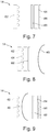
- the image forming device 14 of the seventh embodiment is shown in FIG FIG. 8 shown.
- the image generating device 14 comprises a light source 62 and a display unit 64, wherein the light source 62 is executed here as a backlight for the display unit 64.
- the light source 62 is attached directly to the display unit 64 and thus quasi-integral with it.
- the image generation device 14 comprises a first filter 66, which adjoins the display unit 64 directly. Again, the first filter 66 is optional and may be omitted in an alternative embodiment.
- the image generating device 14 includes the diffuser 46, which is arranged in the beam path of the light 16 behind the first filter 66. With regard to possible embodiments of the diffuser 46, the above statements apply.
- the image forming device 14 of the eighth embodiment is shown in FIG FIG. 9 shown.
- the image forming device 14 of the eighth embodiment is substantially identical to the image forming device 14 of the first embodiment, and further includes a diffuser 46.
- the image forming device 14 of the eighth embodiment includes a light source 62 and a display unit 64, the light source 62 also being referred to herein as Backlight for the display unit 64 is executed.
- the image forming device 14 includes first and second filters 66, 68 positioned on both sides of the display unit 64. The filters 66, 68 are optional and may be omitted in an alternative embodiment.
- the image forming device 14 comprises the already mentioned diffuser 46, which is arranged in the beam path of the light 16 between the light source 62 and the display unit 64, concretely between the light source 62 and the second filter 68.
- the diffuser 46 is arranged in the beam path of the light 16 behind the first filter 66.
Landscapes
- Physics & Mathematics (AREA)
- General Physics & Mathematics (AREA)
- Optics & Photonics (AREA)
- Engineering & Computer Science (AREA)
- Chemical & Material Sciences (AREA)
- Combustion & Propulsion (AREA)
- Transportation (AREA)
- Mechanical Engineering (AREA)
- Instrument Panels (AREA)
Abstract
Description
- Die vorliegende Erfindung betrifft eine Anzeigevorrichtung als Head-up Display für ein Fahrzeug mit einer Bilderzeugungseinrichtung, die ausgeführt ist, Licht zur Darstellung eines virtuellen Bildes beziehungsweise einer virtuellen Anzeige abzustrahlen, wobei die Bilderzeugungseinrichtung eine Lichtquelle und eine Displayeinheit umfasst, und die Lichtquelle das Licht abstrahlt und die Displayeinheit ein Bild bzw. eine Anzeige erzeugt, einer Optikeinrichtung, die ausgeführt ist, das von der Bilderzeugungseinrichtung abgestrahlte Licht auf ein Anzeigeelement zu projizieren, und einem Diffusor, der in einem Strahlengang des von der Lichtquelle abgestrahlten Lichts angeordnet ist, so dass von der Lichtquelle abgestrahltes Licht über eine Eintrittsfläche in den Diffusor eintritt und über eine Austrittsfläche aus dem Diffusor austritt.
- Auch betrifft die vorliegende Erfindung ein Fahrzeug mit einer obigen Anzeigevorrichtung.
- Des Weiteren betrifft die vorliegende Erfindung ein Verfahren zur Herstellung einer Anzeigevorrichtung als Head-up Display für ein Fahrzeug, umfassend die Schritte Bereitstellen einer Bilderzeugungseinrichtung, die ausgeführt ist, Licht mit einer Bildinformation abzustrahlen, wobei die Bilderzeugungseinrichtung eine Lichtquelle und eine Displayeinheit umfasst, und die Lichtquelle das Licht abstrahlt und die Displayeinheit ein Bild bzw. eine Anzeige erzeugt, Bereitstellen und Anordnen einer Optikeinrichtung, die ausgeführt ist, das von der Bilderzeugungseinrichtung abgestrahlte Licht auf ein Anzeigeelement zu projizieren, Bereitstellen eines Diffusors als im Wesentlichen ebene Platte, und Anordnen des Diffusors in einem Strahlengang des von der Lichtquelle abgestrahlten Lichts, so dass von der Lichtquelle abgestrahltes Licht über eine Eintrittsfläche in den Diffusor eintritt und über eine Austrittsfläche aus dem Diffusor austritt.
- Es sind verschiedene Anzeigevorrichtungen für Fahrzeuge bekannt, die insbesondere als Head-up Displays (HUD) bekannt sind. Gelegentlich werden derartige Anzeigevorrichtungen auch als Kopf-oben-Anzeigevorrichtungen bezeichnet, wobei die englische Bezeichnung allerdings auch in der deutschen Sprache Einzug gefunden hat. Eine derartige Anzeigevorrichtung umfasst üblicherweise eine Bilderzeugungseinrichtung, mit der Licht abgestrahlt werden kann. Ferner umfasst die Anzeigevorrichtung eine Optikeinrichtung, welche beispielsweise einen oder mehrere Spiegel umfassen kann. Mit der Optikeinrichtung kann das von der Bilderzeugungseinrichtung abgestrahlte Licht auf ein Anzeigeelement projiziert werden. Das Anzeigeelement weist eine semitransparente Spiegelfläche auf. Diese semitransparente Spiegelfläche kann beispielsweise durch einen Bereich der Windschutzscheibe des Fahrzeugs bereitgestellt werden. Ferner sind Anzeigevorrichtungen bekannt, die einen sogenannten Combinerspiegel beziehungsweise Kombinierspiegel aufweisen, der die semitransparente Spiegelfläche umfasst. Durch eine Überlagerung der auf den Spiegel projizierten Information, welche von diesem reflektiert wird, mit einer durch den Spiegel hindurch scheinenden Information aus einer hinter dem Spiegel gelegenen Umgebung kann somit ein virtuelles Bild beziehungsweise eine virtuelle Anzeige bereitgestellt werden.
- Derartige Anzeigevorrichtungen werden üblicherweise in einem Innenraum des Fahrzeugs montiert. Die virtuelle Anzeige wird üblicherweise in einer sogenannten Eyebox für einen Fahrzeugführer erzeugt. Die Eyebox beschreibt einen Bereich in dem Innenraum des Fahrzeugs, in dem sich die Augen des Fahrzeugführers befinden müssen, um das virtuelle Bild beziehungsweise die virtuelle Anzeige der Anzeigevorrichtung sehen zu können. Bei einer Bewegung der Augen aus der Eyebox hinaus, kann der Fahrzeugführer das virtuelle Bild beziehungsweise die virtuelle Anzeige nicht mehr wahrnehmen.
- Die Anzeigevorrichtungen besitzen häufig Diffusoren, um Licht unter definierten Winkeln in gewünschte Raumwinkel zu lenken und eine direkte Sichtbarkeit der Lichtquelle durch Lichtmischung zu vermeiden. Es gibt verschiedene Arten von Diffusoren, einfache sandgestrahlte Glasplatten bis hin zu speziell ausgelegten holographischen Diffusoren. Typischerweise werden optische Strukturen auf ein Substrat wie Folie oder Kunststoffplatte aufgebracht. Die Lichtverteilung für diese Diffusoren ist gegeben, wenn nahezu paralleles, gerichtetes, sogenanntes kollimiertes, Licht normal auf den Diffusor trifft. Dann wird das Licht an der optischen Struktur des Diffusors gebrochen und in den ausgelegten Winkelbereich, beispielsweise 20° zirkular, gelenkt. Der Diffusor kann also beispielsweise als ein zweidimensionales Feld mit optischen Strukturen ausgeführt sein. Insbesondere bei HUD Anwendungen ist es eine große Herausforderung, die Eyebox, d.h. den Bereich, in dem ein Fahrer das virtuelle Bild beziehungsweise die virtuelle Anzeige sehen kann, homogen auszuleuchten. Gleichzeitig ist es wünschenswert, dass möglichst viel des von der Anzeigevorrichtung erzeugten Lichts in die Eyebox gelangt, um eine elektrische Leistungsaufnahme der Anzeigevorrichtung zu begrenzen. Bei einer ideal effizienten Beleuchtung würde alles erzeugte Licht homogen auf der Fläche der Eyebox verteilt.
- In diesem Zusammenhang ist aus der
US 2014/0085570 A1 eine Hintergrundbeleuchtung bekannt, in der eine Verringerung der Helligkeit bei einem Randabschnitt verknüpft mit der Änderung einer Betrachtungsdistanz reduziert wird. Die Hintergrundbeleuchtung umfasst ein optisches Bauteil zum Transformieren von Strahlen, die von Lichtquellen projiziert worden sind, in Strahlen mit einer Schmalwinkel-Lichtverteilung, in der Wellenstrahlen mit einer Intensität von nicht weniger als einem vorbestimmten Wert innerhalb eines vorbestimmten Winkelbereichs örtlich festgelegt sind, der in der Normalrichtung einer Anzeigeoberfläche eines Flüssigkristallanzeige-Panels zentriert ist, und zum Projizieren der transformierten Strahlen in die Richtung des Flüssigkristallanzeige-Panels; und ein Lichtverteilungs-Steuerbauteil zum Empfangen der Strahlen, die von dem optischen Bauteil projiziert werden, und die die Schmalwinkel-Lichtverteilung haben, und zum Projizieren der empfangenen Strahlen in die Richtung des Flüssigkristallanzeige-Panels. Eine Vielzahl von Konkavelementen ist bei dem Lichtverteilungs-Steuerbauteil bereitgestellt zum Transformieren eines Strahls aus der Reihe der Strahlen mit der Schmalwinkel-Lichtverteilung, der in einen Randabschnitt des Flüssigkristallanzeige-Panels eintritt, so dass die Schmalwinkel-Lichtverteilung des eingetretenen Strahls verbreitert wird im Vergleich zu der eines Strahls, der in einen Zentralabschnitt des Flüssigkristallanzeige-Panels eintritt; und Krümmungsradien der Vielzahl von Konkavelementen gebildet sind. Dabei ist ein Krümmungsradius eines Konkavelementes, das bei einem Randabschnitt des Lichtverteilungs-Steuerbauteils gelegen ist, kleiner als ein Krümmungsradius eines Konkavelementes, das bei einem Zentralabschnitt des Lichtverteilungs-Steuerbauteils gelegen ist. - Auch ist aus der
US 2016/0062114 A1 eine elektronische Anzeige für verminderte Rückstrahlungen bekannt. Ein optisches System, das Reflektionen von einer elektronischen Anzeige verringert, kann eine elektronische Anzeige und ein Lichtlenkmedium umfassen. Das Lichtlenkmedium ist konfiguriert, eine Vielzahl von Betrachtungskegeln in ein Augenbewegungsfeld, das der Anzeige zugewandt ist, zu lenken, so dass die Betrachtungskegel zumindest teilweise an der Augenbewegungsfeld-Ebene überlappen, wobei ein Betrachtungskegel eine geometrische Position ist, innerhalb der ein Betrachters nur Licht, welches von der elektronischen Anzeige kommt, sehen kann. - Ausgehend von dem oben genannten Stand der Technik liegt der Erfindung somit die Aufgabe zugrunde, eine Anzeigevorrichtung als Head-up Display für ein Fahrzeug, ein Fahrzeug mit einer solchen Anzeigevorrichtung und ein Verfahren zur Herstellung einer solchen Anzeigevorrichtung anzugeben, die eine zuverlässige und gut erkennbare Darstellung von einem virtuellen Bild beziehungsweise einer virtuellen Anzeige ermöglichen.
- Die Lösung der Aufgabe erfolgt erfindungsgemäß durch die Merkmale der unabhängigen Ansprüche. Vorteilhafte Ausgestaltungen der Erfindung sind in den Unteransprüchen angegeben.
- Erfindungsgemäß ist somit eine Anzeigevorrichtung als Head-up Display für ein Fahrzeug angegeben mit einer Bilderzeugungseinrichtung, die ausgeführt ist, Licht zur Darstellung eines virtuellen Bildes beziehungsweise einer virtuellen Anzeige abzustrahlen, wobei die Bilderzeugungseinrichtung eine Lichtquelle und eine Displayeinheit umfasst, und die Lichtquelle das Licht abstrahlt und die Displayeinheit ein Bild bzw. eine Anzeige erzeugt, einer Optikeinrichtung, die ausgeführt ist, das von der Bilderzeugungseinrichtung abgestrahlte Licht auf ein Anzeigeelement zu projizieren, und einem Diffusor, der in einem Strahlengang des von der Lichtquelle abgestrahlten Lichts angeordnet ist, so dass von der Lichtquelle abgestrahltes Licht über eine Eintrittsfläche in den Diffusor eintritt und über eine Austrittsfläche aus dem Diffusor austritt, wobei die Austrittsfläche insgesamt eine Wölbung aufweist, um das von der Lichtquelle abgestrahlte Licht in einer Eyebox der Anzeigevorrichtung zu bündeln.
- Erfindungsgemäß ist außerdem ein Fahrzeug mit einer obigen Anzeigevorrichtung angegeben.
- Weiter ist erfindungsgemäß ein Verfahren zur Herstellung einer Anzeigevorrichtung als Head-up Display für ein Fahrzeug angegeben, umfassend die Schritte Bereitstellen einer Bilderzeugungseinrichtung, die ausgeführt ist, Licht mit einer Bildinformation abzustrahlen, wobei die Bilderzeugungseinrichtung eine Lichtquelle und eine Displayeinheit umfasst, und die Lichtquelle das Licht abstrahlt und die Displayeinheit ein Bild bzw. eine Anzeige erzeugt, Bereitstellen und Anordnen einer Optikeinrichtung, die ausgeführt ist, das von der Bilderzeugungseinrichtung abgestrahlte Licht auf ein Anzeigeelement zu projizieren, Bereitstellen eines Diffusors als im Wesentlichen ebene Platte, und Anordnen des Diffusors in einem Strahlengang des von der Lichtquelle abgestrahlten Lichts, so dass von der Lichtquelle abgestrahltes Licht über eine Eintrittsfläche in den Diffusor eintritt und über eine Austrittsfläche aus dem Diffusor austritt, wobei das Verfahren ein Biegen des Diffusors umfasst, so dass die Eintrittsfläche insgesamt eine Wölbung aufweist, um das von der Lichtquelle abgestrahlte Licht in einer Eyebox der Anzeigevorrichtung zu bündeln.
- Grundidee der vorliegenden Erfindung ist es also, durch die Wölbung der Austrittsfläche das von dem Diffusor abgestrahlte Licht in der Eyebox zu bündeln und ihre Ausleuchtung zu verbessern. Durch eine Wahl von einem Kurvenradius der Wölbung, der klein im Vergleich zu Größe des Diffusors ist, wird ein benötigter Austrittswinkel für das Licht nicht überschritten. Das von der Bilderzeugungseinrichtung abgestrahlte Licht wird dabei als im Wesentlichen kollimar angesehen. Die Wölbung kann einfach bereitgestellt werden.
- Das Anzeigeelement kann beispielsweise durch einen Bereich einer Windschutzscheibe des Fahrzeugs bereitgestellt werden. Das Anzeigeelement umfasst vorzugsweise eine semitransparente Spiegelfläche. Durch eine Überlagerung von auf den Spiegel projizierten Informationen, welche von diesem reflektiert werden, zusammen mit einer durch den Spiegel hindurch scheinenden Information aus einer hinter dem Spiegel gelegenen Umgebung, kann somit ein virtuelles Bild beziehungsweise eine virtuelle Anzeige bereitgestellt werden. Die semitransparente Spiegelfläche kann durch eine Anordnung des Anzeigeelements mit entsprechenden Winkeln zu dem von der Bilderzeugungseinrichtung abgestrahlten Licht und von Licht der durch den Spiegel hindurch scheinenden Information erzielt werden.
- Die Darstellung eines virtuellen Bildes beziehungsweise einer virtuellen Anzeige betrifft eine Projektion von Informationen für einen Fahrzeugführer. Die Informationen können das Fahrzeug selber betreffen, beispielsweise eine aktuelle Geschwindigkeit, Fahrzeugstatusinformationen, beispielsweise einen Füllstand eines Kraftstoffbehälters oder eine Information über eine geöffnete Tür, Streckeninformationen, beispielsweise Routeninformationen, Hindernisse, aktuelle Verbote oder Gebote zum Führen des Fahrzeugs, oder auch - im Stand - Multimediainformationen zur Unterhaltung oder Information des Fahrzeugführers. Die Informationen werden von der Bilderzeugungseinrichtung mit dem Licht abgestrahlt.
- Dabei wird das von der Displayeinheit dargestellte Bild bzw. die von der Displayeinheit dargestellte Anzeige als virtuelles Bild beziehungsweise virtuelle Anzeige in der Eyebox dargestellt. Die Displayeinheit liefert also die Bildinformationen, mit denen das Licht von der Bilderzeugungseinheit abgestrahlt wird.
- Die Optikeinrichtung kann eine beliebige optische Einrichtung sein, um das von der Bilderzeugungseinrichtung abgestrahlte Licht auf das Anzeigeelement zu projizieren, beispielsweise mit Spiegeln und/oder Linsen. Auch kann die Optikeinrichtung weitere optische Elemente enthalten, beispielsweise Filter.
- Der Diffusor kann aus einem prinzipiell beliebigen transmissiven Material gefertigt sein, beispielsweise aus Glas oder vorzugsweise aus einem lichtdurchlässigen Kunststoffmaterial.
- Die Eintrittsfläche kann eine prinzipiell beliebige Form aufweisen. Die Eintrittsfläche kann beispielsweise eine gerade Fläche sein, oder selber eine Wölbung aufweisen. Das Licht tritt über die Eintrittsfläche in den Diffusor ein, so dass die Eintrittsfläche ausgeführt und angeordnet sein muss, dass das von der Bilderzeugungseinrichtung abgestrahlte Licht in einem geeigneten Winkel darauf trifft, so dass das Licht nicht ganz oder überwiegend reflektiert wird. Die Eintrittsfläche kann als insgesamt ebene Fläche ausgebildet. Unbenommen davon kann die Eintrittsfläche lokale Strukturen aufweisen.
- Die Austrittsfläche weist insgesamt eine Wölbung, was bedeutet, dass eine im Wesentlichen einheitliche Wölbung über die Austrittsfläche ausgebildet ist. Unbenommen davon kann die Austrittsfläche lokale Strukturen aufweisen, die die Wölbung verändern.
- In vorteilhafter Ausgestaltung der Erfindung ist der Diffusor in der Bilderzeugungseinrichtung angeordnet. Die Anordnung des Diffusors in der Bilderzeugungseinrichtung ermöglicht eine einfache Bereitstellung und Verwendung des Diffusors. Vorzugsweise ist die Bilderzeugungseinrichtung mit dem Diffusor entsprechend vorkonfiguriert, dass die Bilderzeugungseinrichtung mit dem enthaltenen Diffusor durch eine Anbringung an dem Fahrzeug automatisch verwendet werden kann.
- In vorteilhafter Ausgestaltung der Erfindung ist der Diffusor zwischen der Lichtquelle und der Displayeinheit angeordnet. Das von der Lichtquelle abgestrahlte Licht kann also bereits vor einem Erreichen der Displayeinheit entsprechend beeinflusst werden, um in der Eyebox gebündelt zu erscheinen.
- In vorteilhafter Ausgestaltung der Erfindung ist der Diffusor in einem Strahlengang des von der Lichtquelle abgestrahlten Lichts hinter der Displayeinheit angeordnet ist. Dies ermöglicht eine Kompakte Anordnung von Lichtquelle und Displayeinheit.
- In vorteilhafter Ausgestaltung der Erfindung ist der Diffusor in einem Strahlengang des von der Lichtquelle abgestrahlten Lichts hinter der Bilderzeugungseinrichtung angeordnet ist. Der Diffusor ist also beispielsweise Teil der Optikeinrichtung sein. Die Anordnung des Diffusors hinter der Bilderzeugungseinrichtung ermöglicht große Freiheiten in Bezug auf die Positionierung des Diffusors und damit auch auf eine Gestaltung des Diffusors.
- In vorteilhafter Ausgestaltung der Erfindung ist die Wölbung des Diffusors derart ausgeführt, dass die Austrittsfläche ein Winkelsegment von maximal etwa 30°, vorzugsweise maximal etwa 20°, umfasst. Entsprechende Winkelsegmente sind einerseits als Maximalwert anzusehen, da andernfalls das Licht zumindest in Randbereichen davon nicht mehr wie gewünscht durch die Austrittsfläche austreten kann. Außerdem ergibt sich für übliche Fahrzeuge ein Aufbau, der geeignete Verhältnisse zwischen Diffusor, Anzeigeelement, Abstand zwischen Anzeigeelement und Diffusor, wie auch anderen Größen bewirkt. Bei einem Winkelsegment von 20° ergibt sich beispielsweise ein maximaler Winkel von 10° zu beiden Seiten von einer Mittelposition des Diffusors. Es ergibt sich entsprechend ein maximaler Austrittswinkel von etwa 10°.
- In vorteilhafter Ausgestaltung der Erfindung weist der Diffusor einen im Wesentlichen konstanten Abstand zwischen der Eintrittsfläche und der Austrittsfläche auf. Der Diffusor weist also eine im Wesentlichen konstante Dicke auf. Der Diffusor kann entsprechend beispielsweise als gewölbte Scheibe ausgeführt sein. Es ergibt sich für die Eintrittsfläche ein Kurvenradius in Übereinstimmung mit der Wölbung der Austrittsfläche. Somit kann erreicht werden, dass ein benötigter Einfallswinkel für von der Bilderzeugungseinrichtung abgestrahltes Licht von beispielsweise +/-10° bezogen auf eine Hauptausbreitungsrichtung des Lichts nicht überschritten wird. Auch die Eintrittsfläche weist somit eine im Wesentlichen einheitliche Wölbung auf. Der Abstand zwischen der Eintrittsfläche und der Austrittsfläche ist nur im Wesentlichen konstant, da neben Bauteilschwankungen an der Eintrittsfläche und/oder der Austrittsfläche optische Strukturen ausgeformt sein können, um das von der Bilderzeugungseinrichtung abgestrahlte Licht in einer gewünschten Weise auf das Anzeigeelement zu projizieren. Diese optischen Strukturen können die Dicke des Diffusors lokal verändern.
- In vorteilhafter Ausgestaltung der Erfindung ist der Diffusor an seiner Austrittsfläche mit einer Mehrzahl optischer Strukturen ausgeführt, wobei die optischen Strukturen eine Abstrahlcharakteristik zur Bündelung des abgestrahlten Lichts aufweisen. Die optischen Strukturen können in dem Diffusor an der Seite der Austrittsfläche ausgeformt sein. Alternativ oder zusätzlich können die optischen Strukturen auf den Diffusor an der Seite der Austrittsfläche aufgebracht sein. Die optischen Strukturen beeinflussen ein Austreten des von der von der Bilderzeugungseinrichtung abgestrahlten Lichts aus dem Diffusor. Dadurch kann der Diffusor das von der Bilderzeugungseinrichtung abgestrahlte Licht in einer gewünschten Weise auf das Anzeigeelement projizieren. Durch die optischen Strukturen kann insbesondere eine zusätzliche Richtwirkung des von der Bilderzeugungseinrichtung abgestrahlten Lichts zu der Eyebox erzielt werden. Vorzugsweise weisen die optischen Strukturen eine matrixartige Anordnung auf. Mit den optischen Strukturen kann eine besonders homogene Lichtverteilung in der Eyebox erzielt werden, indem das Licht in auszuleuchtende Bereiche gelenkt werden kann. Entsprechend kann der Diffusor auch an seiner Eintrittsfläche mit einer Mehrzahl optischer Strukturen ausgeführt sein, wobei die optischen Strukturen eine Einstrahlung des von der abgestrahlten Bilderzeugungseinrichtung abgestrahlten Lichts verbessern und/oder lenken.
- In vorteilhafter Ausgestaltung der Erfindung weisen die optischen Strukturen eine Abstrahlcharakteristik mit einer Halbwertsbreite von nicht mehr als 45°, vorzugsweise von nicht mehr als 35°, weiter bevorzugt von nicht mehr als 30°, auf. Die Halbwertsbreite einer Funktion mit einem Maximum ist die Differenz zwischen den beiden Argumentwerten, für die die Funktionswerte auf die Hälfte des Maximums abgesunken sind, anschaulich also die "Breite bei halber Höhe". Je geringer die Halbwertsbreite, desto stärker wird das Licht gebündelt, und desto gezielter kann das Licht auf das Anzeigeelement projiziert werden.
- In vorteilhafter Ausgestaltung der Erfindung weisen die optischen Strukturen eine Hauptabstrahlrichtung auf, wobei die Hauptabstrahlrichtung senkrecht zu der Austrittsfläche ausgeführt ist. Die Hauptabstrahlrichtung entspricht also zumindest in einem lokalen Bereich bzw. in einer asymptotischen Näherung einer Normalenrichtung auf der Austrittsfläche. Ausgehend von der Wölbung der Austrittsfläche des Diffusors kann somit eine Bündelung des abgestrahlten Lichts erreicht werden. Verluste in Randbereichen des Diffusors bzw. der Eyebox können verringert werden.
- In vorteilhafter Ausgestaltung der Erfindung weisen die optischen Strukturen eine Hauptabstrahlrichtung auf, wobei die Hauptabstrahlrichtung der optischen Strukturen in Richtung zu einem Mittelpunkt der Eyebox ausgeführt ist. Dadurch weist jede optische Struktur einen anderen Winkel der Hauptabstrahlrichtung bezogen auf die Normale der Austrittsfläche auf. Durch die Hauptabstrahlrichtung in Richtung zu dem Mittelpunkt der Eyebox können Verluste in Randbereichen des Diffusors bzw. der Eyebox stärker verringert werden. Basierend auf einer Dimensionierung von Diffusor, Anzeigeelement, und dazwischenliegenden Abständen kann eine homogene Ausleuchtung der Eyebox erzielt werden. Wenn beispielsweise die Halbwertsbreite ungefähr einem Winkel entspricht, der mit einem durch das Anzeigeelement definierten Winkelbereich übereinstimmt, kann im Idealfall für jede optische Struktur das gesamte Licht auf das Anzeigeelement projiziert werden. Es ist nicht erforderlich, das alle optischen Strukturen exakt zu dem Mittelpunkt der Eyebox ausgerichtet sind. Es ist aber Ziel, zumindest einen Anteil von Licht, welches auf das Anzeigeelement trifft, zu vergrößern, um die Ausleuchtung der Eyebox zu verbessern.
- In vorteilhafter Ausgestaltung der Erfindung ist der Diffusor als im Wesentlichen ebene Platte ausgeführt, und die Wölbung ist in dem Diffusor durch Biegen der ebenen Platte ausgebildet. Somit kann der Diffusor mit der Wölbung auf besonders einfache Weise bereitgestellt werden. Entsprechende planare Diffusoren sind prinzipiell bekannt und leicht verfügbar, wodurch sich auch ein Kostenvorteil ergibt. Der Diffusor ist in diesem Fall aus einem vorzugsweise elastisch verformbaren Material hergestellt, besonders bevorzugt aus einem elastisch verformbaren Kunststoff.
- In vorteilhafter Ausgestaltung der Erfindung ist die Anzeigevorrichtung mit dem Anzeigeelement ausgeführt. Das Anzeigeelement ist dabei üblicherweise klappbar, verschwenkbar, linear verschiebbar, oder ähnliches, gehalten, um es bei Nichtbenutzung unsichtbar zu lagern, beispielsweise in einem Armaturenbrett. Das Anzeigeelement weist vorzugsweise eine semitransparente Spiegelfläche auf. Das Anzeigeelement kann beispielsweise als ein sogenannter Combinerspiegel beziehungsweise Kombinierspiegel ausgeführt sein, der die semitransparente Spiegelfläche umfasst.
- Nachfolgend wird die Erfindung unter Bezugnahme auf die anliegende Zeichnung anhand bevorzugter Ausführungsformen näher erläutert. Die dargestellten Merkmale können sowohl jeweils einzeln als auch in Kombination einen Aspekt der Erfindung darstellen. Merkmale verschiedener Ausführungsbeispiele sind übertragebar von einem Ausführungsbeispiel auf ein anderes.
- Es zeigt
- Fig. 1
- eine ausschnittsweise, schematische Darstellung eines Fahrzeugs mit einer Anzeigevorrichtung zur Projektion auf einer Windschutzscheibe des Fahrzeugs gemäß einer ersten, bevorzugten Ausführungsform der vorliegenden Erfindung in einer teilweise freigeschnittenen Seitenansicht,
- Fig. 2
- eine ausschnittsweise, schematische Darstellung eines Fahrzeugs mit einer Anzeigevorrichtung zur Projektion auf einem Combinerspiegel der Anzeigevorrichtung gemäß einer zweiten Ausführungsform der vorliegenden Erfindung in einer teilweise freigeschnittenen Seitenansicht,
- Fig. 3
- eine schematische Darstellung eines Diffusors und einer Eyebox mit in der Austrittsfläche des Diffusors ausgebildeten optischen Strukturen gemäß einer dritten Ausführungsform der vorliegenden Erfindung in einer Seitenansicht,
- Fig. 4
- eine schematische Darstellung eines Diffusors und einer Eyebox mit in der Austrittsfläche des Diffusors ausgebildeten optischen Strukturen gemäß einer vierten Ausführungsform der vorliegenden Erfindung in einer Seitenansicht,
- Fig. 5
- eine Detailansicht einer optischen Struktur des Diffusors aus einer der
Figuren 3 oder 4 mit einer homogenen Lichtverteilung gemäß einer fünften Ausführungsform, - Fig. 6
- eine Detailansicht einer optischen Struktur des Diffusors aus
Figur 4 mit einer gerichteten Lichtverteilung gemäß einer sechsten Ausführungsform, - Fig. 7
- eine schematische Darstellung einer Bilderzeugungseinrichtung zum Bereitstellen eines Bildes zur Projektion auf dem Combinerspiegel der Anzeigevorrichtung in Übereinstimmung mit der ersten Ausführungsform der vorliegenden Erfindung,
- Fig. 8
- eine schematische Darstellung einer Bilderzeugungseinrichtung mit einem Diffusor zum Bereitstellen eines Bildes zur Projektion auf dem Combinerspiegel der Anzeigevorrichtung gemäß einer siebten Ausführungsform der vorliegenden Erfindung, und
- Fig. 9
- eine schematische Darstellung einer Bilderzeugungseinrichtung mit einem Diffusor zum Bereitstellen eines Bildes zur Projektion auf dem Combinerspiegel der Anzeigevorrichtung gemäß einer achten Ausführungsform der vorliegenden Erfindung.
- Die
Figur 1 zeigt eine ausschnittsweise Darstellung eines Fahrzeugs 10 gemäß einer ersten, bevorzugten Ausführungsform der vorliegenden Erfindung. Das Fahrzeug 10 ist in dem vorliegenden Ausführungsbeispiel als Personenkraftwagen ausgebildet. Das Fahrzeug 10 umfasst eine Anzeigevorrichtung 12. Die Anzeigevorrichtung 12 ist in dem vorliegenden Ausführungsbeispiel als Head-up Display, das gelegentlich auch als Kopf-oben-Anzeigevorrichtung bezeichnet wird, ausgeführt. - Die Anzeigevorrichtung 12 umfasst eine Bilderzeugungseinrichtung 14. Von der Bilderzeugungseinrichtung 14 kann Licht 16 abgestrahlt werden. Insbesondere kann mit der Bilderzeugungseinrichtung 14 eine Anzeige beziehungsweise ein Bild bereitgestellt werden.
- Die Bilderzeugungseinrichtung 14 der ersten Ausführungsform ist im Detail in
Fig. 7 dargestellt ist. Die Bilderzeugungseinrichtung 14 umfasst eine Lichtquelle 62 und eine Displayeinheit 64. Entsprechend ist die Lichtquelle 62 vorliegend als Hintergrundbeleuchtung für die Displayeinheit 64 ausgeführt. Zusätzlich umfasst die Bilderzeugungseinrichtung 14 einen ersten und zweiten Filter 66, 68, die an beiden Seiten der Displayeinheit 64 positioniert sind. Die Filter 66, 68 sind optional und können in einer alternativen Ausführungsform weggelassen werden. - Die Displayeinheit 64 ist hier als TFT-Display ausgeführt und kann somit die Anzeige beziehungsweise das Bild bereitstellen. Durch das Beleuchten der Displayeinheit 64 mit der Lichtquelle 62 wird eine auf der Displayeinheit 64 bereitgestellte Anzeige beziehungsweise ein Bild von der Bilderzeugungseinrichtung 14 bereitgestellt beziehungsweise mit dem das Licht 16 abgestrahlt werden kann. Prinzipiell ist es auch bekannt, den Bildschirm frontal zu beleuchten, und die Anzeige beziehungsweise das Bild über entsprechende Reflektionen von frontal eintreffendem Licht zu erzeugen, oder eine selbstleuchtende Displayeinheit 64 breitzustellen.
- Darüber hinaus umfasst die Anzeigevorrichtung 12 eine Optikeinrichtung 18. Die Optikeinrichtung 18 umfasst in dem vorliegenden Ausführungsbeispiel einen ersten Spiegel 20 und einen zweiten Spiegel 22. Das von der Bilderzeugungseinrichtung 14 abgestrahlte Licht 16 trifft zunächst auf den ersten Spiegel 20, und wird von dort auf den zweiten Spiegel 22 reflektiert. Die Optikeinrichtung 18 kann in einer alternativen Ausführungsform weitere optische Elemente wie Spiegel, Linsen und/oder Filter umfassen. Die Bilderzeugungseinrichtung 14 und die Optikeinrichtung 18 sind vorliegend innerhalb eines hier nur angedeuteten Armaturenbretts 24 des Fahrzeugs 10 angeordnet.
- Das Licht 16, das von der Bilderzeugungseinrichtung 14 abgestrahlt wird, wird von dem zweiten Spiegel 22 der Optikeinrichtung 18 auf ein Anzeigeelement 26 projiziert. Das Anzeigeelement 26 ist vorliegend durch einen Teil einer Windschutzscheibe 28 des Fahrzeugs 10 gebildet. Das Anzeigeelement 26 umfasst eine semitransparente Spiegelfläche. Das Licht 16, das auf das Anzeigeelement 26 projiziert wird, wird im Bereich einer Eyebox 30 zu einem Fahrzeugführer 32 des Fahrzeugs 10 reflektiert, wobei die Eyebox 30 so positioniert ist, dass das Licht 16 auf Augen 34 des Fahrzeugführers 32 trifft. Somit überlagert sich das Licht 16, das von der Bilderzeugungseinrichtung 14 auf das Anzeigeelement 26 projiziert wird, mit Licht, das von einem Umgebungsbereich 36 des Fahrzeugs 10 zu den Augen 34 des Fahrzeugführers 32 gelangt. Für den Fahrzeugführer 32 des Fahrzeugs 10 ergibt sich somit eine virtuelle Anzeige 38 beziehungsweise ein virtuelles Bild 38. Die Eyebox 30 beschreibt dabei einen Bereich in einem Innenraum 40 des Fahrzeugs 10, in dem sich die Augen 34 des Fahrzeugführers 32 befinden müssen, um das virtuelle Bild 38 beziehungsweise die virtuelle Anzeige 38 auf dem Anzeigeelement 26 sehen zu können.
- Die Darstellung eines virtuellen Bildes 38 beziehungsweise einer virtuellen Anzeige 38 betrifft eine Projektion von Informationen für den Fahrzeugführer 32. Die Informationen können das Fahrzeug 10 selber betreffen, beispielsweise eine aktuelle Geschwindigkeit, Fahrzeugstatusinformationen, beispielsweise einen Füllstand eines Kraftstoffbehälters oder eine Information über eine geöffnete Tür, und/oder Streckeninformationen, beispielsweise Routeninformationen, Hindernisse, aktuelle Verbote oder Gebote zum Führen des Fahrzeugs 10. Im Stand können auch Multimediainformationen zur Unterhaltung oder Information des Fahrzeugführers 10 projiziert werden. Die Informationen werden von der Bilderzeugungseinrichtung 14 mit dem Licht 16 abgestrahlt.
- Die
Figur 2 zeigt eine ausschnittsweise Darstellung eines Fahrzeugs 10 mit einer Anzeigevorrichtung 12 gemäß einer zweiten Ausführungsform der vorliegenden Erfindung. Das Fahrzeug 10 und die Anzeigevorrichtung 12 der zweiten Ausführungsform stimmen weitgehend mit dem Fahrzeug 10 und der Anzeigevorrichtung 12 der ersten Ausführungsform überein, so dass hier nur Unterschiede zwischen dem Fahrzeug 10 und der Anzeigevorrichtung 12 der ersten und zweiten Ausführungsform im Detail betrachtet werden. Nicht im Detail erörterte Merkmale des Fahrzeugs 10 und der Anzeigevorrichtung 12 der zweiten Ausführungsform stimmen, soweit eine explizite Beschreibung erforderlich ist, im Zweifel mit denen der ersten Ausführungsform überein. - In diesem Ausführungsbeispiel umfasst die Anzeigevorrichtung 12 als Anzeigeelement 26 einen Combinerspiegel 42, der vorliegend in einem Innenraum 40 des Fahrzeugs 10 in einem Bereich unterhalb der Windschutzscheibe 28 positioniert ist. Der Combinerspiegel 42, der auch als Combiner 42 bezeichnet werden kann, ist mit einer Verstelleinrichtung 44 verstellbar, insbesondere verschwenkbar, an dem Armaturenbrett 24 gehalten. Der Combinerspiegel 42 kann mit der Verstelleinrichtung 44 einerseits in seiner Neigung eingestellt werden. Andererseits kann der Combinerspiegel 42 mit der Verstelleinrichtung 44 bei Nichtbenutzung in eine Lagerposition verschwenkt werden. Die Lagerposition ist in diesem Ausführungsbeispiel in dem Armaturenbrett 24 angeordnet.
- Ferner umfasst die Optikeinrichtung 18 einen ersten Spiegel 20, über den von der Bilderzeugungseinrichtung 14 abgestrahltes Licht 16 unmittelbar auf den Combinerspiegel 42 reflektiert wird. Das Licht 16, das von der Bilderzeugungseinrichtung 14 abgestrahlt wird, wird also mit dem ersten Spiegel 20 auf den Combinerspiegel 42 projiziert. Ein zweiter Spiegel 22, der in der Optikeinrichtung 18 der ersten Ausführungsform vorgesehen ist, entfällt.
- Der Combinerspiegel 42 umfasst eine semitransparente Spiegelfläche. Damit kann über den Combinerspiegel 42 in Übereinstimmung mit der ersten Ausführungsform eine virtuelle Anzeige 38 beziehungsweise ein virtuelles Bild 38 erzeugt werden, welche in einer Eyebox 30 von dem Fahrzeugführer 32 gesehen werden können.
-
Fig. 3 zeigt eine Anordnung eines Diffusors 46 in einem Strahlengang des von der Bilderzeugungseinrichtung 14 abgestrahlten Lichts 16 gemäß einer dritten Ausführungsform. Der Diffusor 46 ist also in nicht explizit dargestellter Weise außerhalb der Bilderzeugungseinrichtung 14 positioniert. Alternativ kann der Diffusor 46 auch ausgehend von der Lichtquelle 62 an einer beliebigen Stelle im Strahlengang des von der Lichtquelle 62 abgestrahlten Lichts 16 innerhalb der Bilderzeugungseinrichtung 14 positioniert sein. Der Diffusor 46 kann also auf jeder Seiter der Displayeinheit 64 positioniert sein. - Die Anordnung und Ausgestaltung des Diffusors 46 gemäß der dritten Ausführungsform ist mit dem Fahrzeug 10 und der Anzeigevorrichtung 12 jeder der zuvor beschriebenen ersten oder zweiten Ausführungsform kombinierbar. Der Diffusor 46 kann innerhalb der Optikeinrichtung 16 in einem Strahlengang des von der Bilderzeugungseinrichtung 14 abgestrahlten Lichts 16 angeordnet sein. Ggf. kann der Diffusor 46 bereits als Teil der Bilderzeugungseinrichtung 14 ausgeführt sein.
- Der Diffusor 46 ist aus einem transmissiven, elastisch verformbaren Kunststoffmaterial als im Wesentlichen ebene Platte mit einer im Wesentlichen konstanten Dicke gefertigt. Die ebene Platte ist insgesamt gebogen, so dass der fertige Diffusor 46 eine entsprechende Biegung aufweist.
- Der Diffusor 46 weist eine Eintrittsfläche 48, über die von der Bilderzeugungseinrichtung 14 abgestrahltes Licht 16 in den Diffusor 46 eintritt, und eine Austrittsfläche 50 für eine Abstrahlung des eingestrahlten Lichts 16 auf, wobei ein Abstand zwischen der Eintrittsfläche 48 und der Austrittsfläche 50 im Wesentlichen konstant ist. Die Eintrittsfläche 48 und die Austrittsfläche 50 weisen durch die Biegung jeweils insgesamt eine im Wesentlichen einheitliche Wölbung auf. Die Wölbung des Diffusors 46 ist derart ausgeführt, dass die Eintrittsfläche 48 und die Austrittsfläche 50 ein Winkelsegment von etwa 20° umfassen. Entsprechend trifft das von der Bilderzeugungseinrichtung 14 abgestrahlte Licht 16 auch in einem Randbereich des Diffusors 46 mit einem Winkel von maximal 10° auf die Eintrittsfläche 48. Durch die Wölbung des Diffusors 46 und der damit einhergehenden Wölbung der Austrittsfläche 50 wird das von der Bilderzeugungseinrichtung 14 abgestrahlte Licht 16 von dem Diffusor 46 in der Eyebox 30 gebündelt.
- Wie in
Fig. 3 gezeigt, ist der Diffusor 46 an seiner Austrittsfläche 50 mit einer Mehrzahl optischer Strukturen 52 ausgeführt, die eine Abstrahlcharakteristik 54 zur Bündelung des abgestrahlten Lichts 16 aufweisen. Die optischen Strukturen 52 sind in dem Diffusor 46 an der Seite der Austrittsfläche 50 ausgeformt und weisen eine matrixartige Anordnung auf. Die Abstrahlcharakteristik 54 der optischen Strukturen 52 ist inFig. 5 im Detail dargestellt. In diesem Ausführungsbeispiel weisen die optischen Strukturen 52 eine identische Abstrahlcharakteristik 54 mit einer Halbwertsbreite von etwa 30° auf. Die Halbwertsbreite einer Funktion mit einem Maximum ist dabei eine Differenz zwischen den beiden Argumentwerten, für die die Funktionswerte auf die Hälfte des Maximums abgesunken sind, anschaulich also die "Breite bei halber Höhe". - Wie entsprechend in
Fig. 3 ersichtlich, weisen die optischen Strukturen 52 eine Hauptabstrahlrichtung 56 auf, die jeweils senkrecht zu der Austrittsfläche 50 ausgeführt ist. Zusätzlich sind inFig. 3 die seitlichen Abstrahlrichtungen 58 für die Abstrahlung mit einer halben Intensität verglichen mit der Hauptabstrahlrichtung 56 angegeben. - Durch die optischen Strukturen 52 und Ihre Richtwirkung wird eine zusätzliche Richtwirkung des von der Bilderzeugungseinrichtung 14 abgestrahlten Lichts 16 zu der Eyebox 30 mit einer homogenen Lichtverteilung in der Eyebox 30 erzielt.
-
Fig. 4 zeigt eine Anordnung eines Diffusors 46 in einem Strahlengang des von der Bilderzeugungseinrichtung 14 abgestrahlten Lichts 16 gemäß einer vierten Ausführungsform. Die Anordnung und Ausgestaltung des Diffusors 46 gemäß der vierten Ausführungsform ist mit dem Fahrzeug 10 und der Anzeigevorrichtung 12 jeder der zuvor beschriebenen ersten oder zweiten Ausführungsform kombinierbar. Der Diffusor 46 kann innerhalb der Optikeinrichtung 16 in einem Strahlengang des von der Bilderzeugungseinrichtung 14 abgestrahlten Lichts 16 angeordnet sein. Ggf. kann der Diffusor 46 als Teil der Bilderzeugungseinrichtung 14 ausgeführt sein. - Der Diffusor 46 der vierten Ausführungsform ist aus einem transmissiven Kunststoffmaterial als gewölbte Scheibe ausgeführt mit einer im Wesentlichen konstanten Dicke ausgeführt. Die Biegung des Diffusors 46 der vierten Ausführungsform ist geringer als die Biegung des Diffusors 46 der dritten Ausführungsform.
- Der Diffusor 46 weist eine Eintrittsfläche 48, über die von der Bilderzeugungseinrichtung 14 abgestrahltes Licht 16 in den Diffusor 46 eintritt, und eine Austrittsfläche 50 für eine Abstrahlung des eingestrahlten Lichts 16 auf, wobei ein Abstand zwischen der Eintrittsfläche 48 und der Austrittsfläche 50 im Wesentlichen konstant ist. Die Eintrittsfläche 48 und die Austrittsfläche 50 weisen durch die Biegung jeweils insgesamt eine im Wesentlichen einheitliche Wölbung auf. Die Wölbung des Diffusors 46 ist derart ausgeführt, dass die Eintrittsfläche 48 und die Austrittsfläche 50 ein Winkelsegment von weniger als 20° umfassen. Entsprechend trifft das von der Bilderzeugungseinrichtung 14 abgestrahlte Licht 16 auch in einem Randbereich des Diffusors 46 mit einem Winkel von weniger als 10° auf die Eintrittsfläche 48. Durch die Wölbung des Diffusors 46 und der damit einhergehenden Wölbung der Austrittsfläche 50 wird das von der Bilderzeugungseinrichtung 14 abgestrahlte Licht 16 von dem Diffusor 46 in der Eyebox 30 gebündelt.
- Wie in
Fig. 4 dargestellt ist, ist der Diffusor 46 an seiner Austrittsfläche 50 mit einer Mehrzahl optischer Strukturen 52 ausgeführt, die eine Abstrahlcharakteristik 54 zur Bündelung des abgestrahlten Lichts 16 aufweisen. Die optischen Strukturen 52 sind in dem Diffusor 46 an der Seite der Austrittsfläche 50 ausgeformt und weisen eine matrixartige Anordnung auf. Die optischen Strukturen 52 weisen jeweils eine Hauptabstrahlrichtung 56 auf, die in Richtung zu einem Mittelpunkt 60 der Eyebox 30 ausgeführt ist. Dadurch weisen die optischen Strukturen 52 unterschiedliche Winkel der Hauptabstrahlrichtung 56 bezogen auf eine Normale der Austrittsfläche 50 auf. So sind in einem Mittelbereich des Diffusors 46 optische Strukturen 52, die im Detail inFig. 5 dargestellt sind, angeordnet. Diese optischen Strukturen 52 weisen in Übereinstimmung mit den optischen Strukturen 52 der dritten Ausführungsform eine Abstrahlcharakteristik 54 mit einer Halbwertsbreite von etwa 30° auf, wobei die Hauptabstrahlrichtung 56 senkrecht zu der Austrittsfläche 50 ausgeführt ist. - In einem Randbereich des Diffusors 46 sind optische Strukturen 52, deren Abstrahlcharakteristik 54 im Detail in
Fig. 6 dargestellt ist, angeordnet. Diese optischen Strukturen 52 weisen eine Abstrahlcharakteristik 54 auf, wobei die Hauptabstrahlrichtung 56 nicht senkrecht zu der Austrittsfläche 50 ausgeführt ist, um insgesamt eine Abstrahlung in Richtung zu dem Mittelpunkt 60 der Eyebox 30 zu bewirken. Durch die optischen Strukturen 52 und Ihre Richtwirkung wird eine zusätzliche Richtwirkung des von der Bilderzeugungseinrichtung 14 abgestrahlten Lichts 16 zu der Eyebox 30 mit einer homogenen Lichtverteilung in der Eyebox 30 erzielt. Dabei ist es nicht erforderlich, das alle optischen Strukturen 52 exakt zu dem Mittelpunkt 60 der Eyebox 30 ausgerichtet sind. Das Licht 16 wird durch die Biegung der Abstrahlfläche 50 zusammen mit der Abstrahlcharakteristik 54 der optischen Strukturen 52 vergleichbar mit dem Diffusor 46 der dritten Ausführungsform in der Eyebox 30 gebündelt. - In einer alternativen Ausführungsform der Anzeigevorrichtung wird ausgehend von der Anzeigevorrichtung 12 der ersten bzw. zweiten Ausführungsform eine der Bilderzeugungseinrichtungen 14 der siebten oder achten Ausführungsform, die in den
Figuren 8 oder 9 dargestellt sind, verwendet. Dabei beinhaltet die jeweilige Bilderzeugungseinrichtung 14 den Diffusor 46, wie untenstehend im Detail erläutert wird. Der Diffusor 46 kann dabei jeweils wie oben unter Bezug auf die Diffusoren 46 der dritten bis sechsten Ausführungsform beschrieben ausgeführt sein. - Die Bilderzeugungseinrichtung 14 der siebten Ausführungsform ist in
Figur 8 dargestellt. Die Bilderzeugungseinrichtung 14 umfasst eine Lichtquelle 62 und eine Displayeinheit 64, wobei die Lichtquelle 62 auch hier als Hintergrundbeleuchtung für die Displayeinheit 64 ausgeführt. In diesem Ausführungsbeispiel ist die Lichtquelle 62 unmittelbar an der Displayeinheit 64 angebracht und somit quasi integral damit ausgeführt. Zusätzlich umfasst die Bilderzeugungseinrichtung 14 einen ersten Filter 66, der sich unmittelbar an die Displayeinheit 64 anschließt. Auch hier ist der erste Filter 66 optional und kann in einer alternativen Ausführungsform weggelassen werden. Außerdem umfasst die Bilderzeugungseinrichtung 14 den Diffusor 46, der im Strahlengang des Lichts 16 hinter dem ersten Filter 66 angeordnet ist. In Bezug auf mögliche Ausgestaltungen des Diffusors 46 gelten die obigen Ausführungen. - Die Bilderzeugungseinrichtung 14 der achten Ausführungsform ist in
Figur 9 dargestellt. Die Bilderzeugungseinrichtung 14 der achten Ausführungsform ist im Wesentlichen identisch wie die Bilderzeugungseinrichtung 14 der ersten Ausführungsform ausgeführt, und umfasst zusätzlich einen Diffusor 46. Entsprechend umfasst die Bilderzeugungseinrichtung 14 der achten Ausführungsform umfasst eine Lichtquelle 62 und eine Displayeinheit 64, wobei die Lichtquelle 62 auch hier als Hintergrundbeleuchtung für die Displayeinheit 64 ausgeführt ist. Zusätzlich umfasst die Bilderzeugungseinrichtung 14 einen ersten und zweiten Filter 66, 68, die an beiden Seiten der Displayeinheit 64 positioniert sind. Die Filter 66, 68 sind optional und können in einer alternativen Ausführungsform weggelassen werden. - Außerdem umfasst die Bilderzeugungseinrichtung 14 den bereits genannten Diffusor 46, der im Strahlengang des Lichts 16 zwischen der Lichtquelle 62 und der Displayeinheit 64 angeordnet ist, konkret zwischen der Lichtquelle 62 und dem zweiten Filter 68. In Bezug auf mögliche Ausgestaltungen des Diffusors 46 gelten die obigen Ausführungen. In einer alternativen Ausführungsform ist der Diffusor 46 im Strahlengang des Lichts 16 hinter dem ersten Filter 66 angeordnet.
-
- 10
- Fahrzeug
- 12
- Anzeigevorrichtung
- 14
- Bilderzeugungseinrichtung
- 16
- Licht
- 18
- Optikeinrichtung
- 20
- erster Spiegel
- 22
- zweiter Spiegel
- 24
- Armaturenbrett
- 26
- Anzeigeelement
- 28
- Windschutzscheibe
- 30
- Eyebox
- 32
- Fahrzeugführer
- 34
- Auge
- 36
- Umgebungsbereich
- 38
- virtuelle Anzeige, virtuelles Bild
- 40
- Innenraum
- 42
- Combinerspiegel, Combiner
- 44
- Verstelleinrichtung
- 46
- Diffusor
- 48
- Eintrittsfläche
- 50
- Austrittsfläche
- 52
- optische Struktur
- 54
- Abstrahlcharakteristik
- 56
- Hauptabstrahlrichtung
- 58
- seitliche Abstrahlrichtung
- 60
- Mittelpunkt
- 62
- Lichtquelle
- 64
- Displayeinheit, TFT
- 66
- erster Filter
- 68
- zweiter Filter
Claims (15)
- Anzeigevorrichtung (12) als Head-up Display für ein Fahrzeug (10) mit einer Bilderzeugungseinrichtung (14), die ausgeführt ist, Licht (16) zur Darstellung eines virtuellen Bildes (38) beziehungsweise einer virtuellen Anzeige (38) abzustrahlen, wobei die Bilderzeugungseinrichtung (14) eine Lichtquelle (62) und eine Displayeinheit (64) umfasst, und die Lichtquelle (62) das Licht (16) abstrahlt und die Displayeinheit (64) ein Bild bzw. eine Anzeige erzeugt,
einer Optikeinrichtung (18), die ausgeführt ist, das von der Bilderzeugungseinrichtung (14) abgestrahlte Licht (16) auf ein Anzeigeelement (26) zu projizieren, und
einem Diffusor (46), der in einem Strahlengang des von der Lichtquelle (62) abgestrahlten Lichts (16) angeordnet ist, so dass von der Lichtquelle (62) abgestrahltes Licht (16) über eine Eintrittsfläche (48) in den Diffusor (46) eintritt und über eine Austrittsfläche (50) aus dem Diffusor (46) austritt,
dadurch gekennzeichnet, dass
die Austrittsfläche (50) insgesamt eine Wölbung aufweist, um das von der Lichtquelle (62) abgestrahlte Licht (16) in einer Eyebox (30) der Anzeigevorrichtung (12) zu bündeln. - Anzeigevorrichtung (12) nach Anspruch 1, dadurch gekennzeichnet, dass der Diffusor (46) in der Bilderzeugungseinrichtung (14) angeordnet ist.
- Anzeigevorrichtung (12) nach Anspruch 2, dadurch gekennzeichnet, dass der Diffusor (46) zwischen der Lichtquelle (62) und der Displayeinheit (64) angeordnet ist.
- Anzeigevorrichtung (12) nach Anspruch 2, dadurch gekennzeichnet, dass der Diffusor (46) in einem Strahlengang des von der Lichtquelle (62) abgestrahlten Lichts (16) hinter der Displayeinheit (64) angeordnet ist.
- Anzeigevorrichtung (12) nach Anspruch 1, dadurch gekennzeichnet, dass der Diffusor (46) in einem Strahlengang des von der Lichtquelle (62) abgestrahlten Lichts (16) hinter der Bilderzeugungseinrichtung (14) angeordnet ist.
- Anzeigevorrichtung (12) nach einem der vorhergehenden Ansprüche 1 bis 5, dadurch gekennzeichnet, dass
die Wölbung des Diffusors (46) derart ausgeführt ist, dass die Austrittsfläche (50) ein Winkelsegment von maximal etwa 30°, vorzugsweise maximal etwa 20°, umfasst. - Anzeigevorrichtung (12) nach einem der vorhergehenden Ansprüche, dadurch gekennzeichnet, dass
der Diffusor (46) einen im Wesentlichen konstanten Abstand zwischen der Eintrittsfläche (48) und der Austrittsfläche (50) aufweist. - Anzeigevorrichtung (12) nach einem der vorhergehenden Ansprüche, dadurch gekennzeichnet, dass
der Diffusor (46) an seiner Austrittsfläche (50) mit einer Mehrzahl optischer Strukturen (52) ausgeführt ist, wobei die optischen Strukturen (52) eine Abstrahlcharakteristik (54) zur Bündelung des abgestrahlten Lichts (16) aufweisen. - Anzeigevorrichtung (12) nach Anspruch 8, dadurch gekennzeichnet, dass die optischen Strukturen (52) eine Abstrahlcharakteristik (54) mit einer Halbwertsbreite von nicht mehr als 45°, vorzugsweise von nicht mehr als 35°, weiter bevorzugt von nicht mehr als 30°, aufweisen.
- Anzeigevorrichtung (12) nach einem der vorhergehenden Ansprüche 8 oder 9, dadurch gekennzeichnet, dass
die optischen Strukturen (52) eine Hauptabstrahlrichtung (56) aufweisen, wobei die Hauptabstrahlrichtung (52) senkrecht zu der Austrittsfläche (50) ausgeführt ist. - Anzeigevorrichtung (12) nach einem der vorhergehenden Ansprüche 8 oder 9, dadurch gekennzeichnet, dass
die optischen Strukturen (52) eine Hauptabstrahlrichtung (56) aufweisen, wobei die Hauptabstrahlrichtung (56) der optischen Strukturen (52) in Richtung zu einem Mittelpunkt (60) der Eyebox (30) ausgeführt ist. - Anzeigevorrichtung (12) nach einem der vorhergehenden Ansprüche, dadurch gekennzeichnet, dass
der Diffusor (46) als im Wesentlichen ebene Platte ausgeführt ist, und die Wölbung in dem Diffusor (46) durch Biegen der ebenen Platte ausgebildet ist. - Anzeigevorrichtung (12) nach einem der vorhergehenden Ansprüche, dadurch gekennzeichnet, dass
die Anzeigevorrichtung (12) mit dem Anzeigeelement (26) ausgeführt ist. - Fahrzeug (10) mit einer Anzeigevorrichtung (12) nach einem der vorhergehenden Ansprüche.
- Verfahren zur Herstellung einer Anzeigevorrichtung (12) als Head-up Display für ein Fahrzeug (10) umfassend die Schritte
Bereitstellen einer Bilderzeugungseinrichtung (14), die ausgeführt ist, Licht (16) mit einer Bildinformation abzustrahlen, wobei die Bilderzeugungseinrichtung (14) eine Lichtquelle (62) und eine Displayeinheit (64) umfasst, und die Lichtquelle (62) das Licht (16) abstrahlt und die Displayeinheit (64) ein Bild bzw. eine Anzeige erzeugt,
Bereitstellen und Anordnen einer Optikeinrichtung (18), die ausgeführt ist, das von der Bilderzeugungseinrichtung (14) abgestrahlte Licht (16) auf ein Anzeigeelement (26) zu projizieren,
Bereitstellen eines Diffusors (46) als im Wesentlichen ebene Platte, und Anordnen des Diffusors (46) in einem Strahlengang des von der Lichtquelle (62) abgestrahlten Lichts (16), so dass von der Lichtquelle (62) abgestrahltes Licht (16) über eine Eintrittsfläche (48) in den Diffusor (46) eintritt und über eine Austrittsfläche (50) aus dem Diffusor (46) austritt,
dadurch gekennzeichnet, dass
das Verfahren ein Biegen des Diffusors (46) umfasst, so dass die Eintrittsfläche (48) insgesamt eine Wölbung aufweist, um das von der Lichtquelle (62) abgestrahlte Licht (16) in einer Eyebox (30) der Anzeigevorrichtung (12) zu bündeln.
Applications Claiming Priority (1)
| Application Number | Priority Date | Filing Date | Title |
|---|---|---|---|
| DE102017120598.5A DE102017120598A1 (de) | 2017-09-07 | 2017-09-07 | Head-up Display mit Diffusor für ein Fahrzeug |
Publications (2)
| Publication Number | Publication Date |
|---|---|
| EP3460539A1 true EP3460539A1 (de) | 2019-03-27 |
| EP3460539B1 EP3460539B1 (de) | 2022-06-08 |
Family
ID=63371509
Family Applications (1)
| Application Number | Title | Priority Date | Filing Date |
|---|---|---|---|
| EP18190355.0A Active EP3460539B1 (de) | 2017-09-07 | 2018-08-23 | Head-up display mit diffusor für ein fahrzeug |
Country Status (3)
| Country | Link |
|---|---|
| EP (1) | EP3460539B1 (de) |
| CN (1) | CN109471261A (de) |
| DE (1) | DE102017120598A1 (de) |
Families Citing this family (3)
| Publication number | Priority date | Publication date | Assignee | Title |
|---|---|---|---|---|
| FR3130712A1 (fr) * | 2021-12-17 | 2023-06-23 | Compagnie Plastic Omnium Se | Pièce de véhicule avec interface utilisateur |
| DE102024128397A1 (de) * | 2024-10-01 | 2026-04-02 | Bayerische Motoren Werke Aktiengesellschaft | Anzeigen mit variierendem Abstrahlwinkelspektrum, insbesondere für ein Fahrzeug |
| DE102024132167A1 (de) * | 2024-11-05 | 2026-05-07 | Valeo Schalter Und Sensoren Gmbh | Projektionsvorrichtung für ein Head-Up-Display, Gehäuseteil und Optikmodulgehäuse für eine Projektionsvorrichtung und Fahrzeug mit einem Head-Up-Display |
Citations (4)
| Publication number | Priority date | Publication date | Assignee | Title |
|---|---|---|---|---|
| FR2858068A1 (fr) * | 2003-07-25 | 2005-01-28 | Thales Sa | Systeme de projection d'images pour viseur tete haute |
| DE102014217180A1 (de) * | 2014-08-28 | 2016-03-03 | Robert Bosch Gmbh | Bilderzeugungsvorrichtung für ein Head-up-Display, Head-up-Display und Verfahren zum Erzeugen eines Bilds für ein Head-up-Display |
| EP3026482A1 (de) * | 2013-07-26 | 2016-06-01 | Nippon Seiki Co., Ltd. | Abtastende projektionsvorrichtung |
| EP3064995A1 (de) * | 2013-10-28 | 2016-09-07 | JVC Kenwood Corporation | Lichtdurchlässiger schirm und bildanzeigevorrichtung damit |
Family Cites Families (9)
| Publication number | Priority date | Publication date | Assignee | Title |
|---|---|---|---|---|
| JP2008518244A (ja) * | 2004-10-22 | 2008-05-29 | コーニンクレッカ フィリップス エレクトロニクス エヌ ヴィ | 投射ディスプレイ装置 |
| JP5287828B2 (ja) * | 2010-10-26 | 2013-09-11 | 株式会社デンソー | ヘッドアップディスプレイ装置 |
| DE112012002308T5 (de) | 2011-05-31 | 2014-02-27 | Mitsubishi Electric Corporation | Hintergrundbeleuchtung und Flüssigkristallanzeigevorrichtung |
| DE102012218360A1 (de) * | 2012-10-09 | 2014-04-10 | Robert Bosch Gmbh | Blickfeldanzeige für ein Fahrzeug |
| IL226434A (en) | 2013-05-19 | 2015-02-26 | Elbit Systems Ltd | Electronic display with reduced refunds |
| US10078217B2 (en) * | 2014-10-24 | 2018-09-18 | Ricoh Company, Ltd. | Image display device and apparatus |
| KR102317356B1 (ko) * | 2015-02-09 | 2021-10-27 | 삼성디스플레이 주식회사 | 표시 장치 및 그 제조 방법 |
| CN106032109A (zh) * | 2015-03-09 | 2016-10-19 | 乔杨 | 用于在挡风玻璃上投影显示的设备 |
| JP6465353B2 (ja) * | 2015-04-28 | 2019-02-06 | 日本精機株式会社 | ヘッドアップディスプレイ装置 |
-
2017
- 2017-09-07 DE DE102017120598.5A patent/DE102017120598A1/de not_active Withdrawn
-
2018
- 2018-08-23 EP EP18190355.0A patent/EP3460539B1/de active Active
- 2018-09-07 CN CN201811043587.9A patent/CN109471261A/zh active Pending
Patent Citations (4)
| Publication number | Priority date | Publication date | Assignee | Title |
|---|---|---|---|---|
| FR2858068A1 (fr) * | 2003-07-25 | 2005-01-28 | Thales Sa | Systeme de projection d'images pour viseur tete haute |
| EP3026482A1 (de) * | 2013-07-26 | 2016-06-01 | Nippon Seiki Co., Ltd. | Abtastende projektionsvorrichtung |
| EP3064995A1 (de) * | 2013-10-28 | 2016-09-07 | JVC Kenwood Corporation | Lichtdurchlässiger schirm und bildanzeigevorrichtung damit |
| DE102014217180A1 (de) * | 2014-08-28 | 2016-03-03 | Robert Bosch Gmbh | Bilderzeugungsvorrichtung für ein Head-up-Display, Head-up-Display und Verfahren zum Erzeugen eines Bilds für ein Head-up-Display |
Also Published As
| Publication number | Publication date |
|---|---|
| EP3460539B1 (de) | 2022-06-08 |
| DE102017120598A1 (de) | 2019-03-07 |
| CN109471261A (zh) | 2019-03-15 |
Similar Documents
| Publication | Publication Date | Title |
|---|---|---|
| DE112017006376B4 (de) | Blickfeldanzeigevorrichtung | |
| DE102013203616B4 (de) | Vorrichtung zur Projektion eines Bildes in einen Anzeigebereich mit Schirm zur Zwischenbildanzeige | |
| DE112019004715B4 (de) | Head-up display | |
| DE102007014298A1 (de) | Headup-Display-Vorrichtung | |
| DE102020103967A1 (de) | Blickfeldanzeigevorrichtung mit einem hellen energieeffizienten Backlight für ein Fahrzeug | |
| WO2019243250A1 (de) | Blickfeldanzeigevorrichtung für ein kraftfahrzeug | |
| DE112017003904T5 (de) | Optische Vorrichtung | |
| DE102018204274A1 (de) | Projektionsanordnung zur Erzeugung einer schwebenden Projektionsanzeige im Inneren eines Kraftfahrzeugs | |
| EP1410096A2 (de) | Projektionsanordnung | |
| DE102015206001A1 (de) | Autostereoskopisches Head-up-Display für ein Fahrzeug und Verfahren zum Erzeugen eines autostereoskopischen Bilds mittels eines Head-up-Displays für ein Fahrzeug | |
| EP3460539B1 (de) | Head-up display mit diffusor für ein fahrzeug | |
| DE102017130376B4 (de) | Anzeigevorrichtung als Head-up Display mit einfacher Eyebox-Verschiebung | |
| DE102018203875A1 (de) | Kraftfahrzeug | |
| WO2023006275A1 (de) | Head-up-display mit einer gleichbleibenden ausrichtung der virtuellen bildebene bei der eyebox-anpassung | |
| DE102017109051A1 (de) | Optisches System und Verfahren zum Betrieb eines HUD | |
| DE112017006586B4 (de) | Anzeigevorrichtung und sich bewegender Körper, der eine Anzeigevorrichtung trägt | |
| DE102020100536B3 (de) | Kopf-Oben-Anzeigevorrichtung für ein Kraftfahrzeug, sowie Verfahren zum Betreiben einer Kopf-oben-Anzeigevorrichtung | |
| DE102021106433A1 (de) | Wellenfrontmanipulator für Head-up-Display, optische Anordnung und Head-up-Display | |
| WO2019238856A1 (de) | Gerät zum generieren eines virtuellen bildes mit mikrolichtquellen | |
| EP4582849A2 (de) | Head-up-display bilderzeugungseinheit mit faltspiegel | |
| DE102022210445A1 (de) | Anzeigeeinrichtung mit Diffusor | |
| DE102022211404B3 (de) | Anzeigevorrichtung mit Lichtwellenleiter | |
| WO2014009186A1 (de) | Bilderzeugende einheit | |
| DE102024123559A1 (de) | Verlustarmer transmissiver Bildgeber und ein damit ausgestattetes HUD in einem Fahrzeug | |
| DE102024209595A1 (de) | Anzeigevorrichtung und Fortbewegungsmittel |
Legal Events
| Date | Code | Title | Description |
|---|---|---|---|
| PUAI | Public reference made under article 153(3) epc to a published international application that has entered the european phase |
Free format text: ORIGINAL CODE: 0009012 |
|
| STAA | Information on the status of an ep patent application or granted ep patent |
Free format text: STATUS: THE APPLICATION HAS BEEN PUBLISHED |
|
| AK | Designated contracting states |
Kind code of ref document: A1 Designated state(s): AL AT BE BG CH CY CZ DE DK EE ES FI FR GB GR HR HU IE IS IT LI LT LU LV MC MK MT NL NO PL PT RO RS SE SI SK SM TR |
|
| AX | Request for extension of the european patent |
Extension state: BA ME |
|
| STAA | Information on the status of an ep patent application or granted ep patent |
Free format text: STATUS: REQUEST FOR EXAMINATION WAS MADE |
|
| 17P | Request for examination filed |
Effective date: 20190927 |
|
| RBV | Designated contracting states (corrected) |
Designated state(s): AL AT BE BG CH CY CZ DE DK EE ES FI FR GB GR HR HU IE IS IT LI LT LU LV MC MK MT NL NO PL PT RO RS SE SI SK SM TR |
|
| REG | Reference to a national code |
Ref country code: DE Ref legal event code: R079 Ref document number: 502018009854 Country of ref document: DE Free format text: PREVIOUS MAIN CLASS: G02B0005020000 Ipc: G02B0027000000 |
|
| RIC1 | Information provided on ipc code assigned before grant |
Ipc: G03B 21/20 20060101ALI20211029BHEP Ipc: G03B 21/00 20060101ALI20211029BHEP Ipc: G02B 5/02 20060101ALI20211029BHEP Ipc: G02B 27/01 20060101ALI20211029BHEP Ipc: G02B 27/00 20060101AFI20211029BHEP |
|
| GRAP | Despatch of communication of intention to grant a patent |
Free format text: ORIGINAL CODE: EPIDOSNIGR1 |
|
| STAA | Information on the status of an ep patent application or granted ep patent |
Free format text: STATUS: GRANT OF PATENT IS INTENDED |
|
| INTG | Intention to grant announced |
Effective date: 20220105 |
|
| GRAS | Grant fee paid |
Free format text: ORIGINAL CODE: EPIDOSNIGR3 |
|
| GRAA | (expected) grant |
Free format text: ORIGINAL CODE: 0009210 |
|
| STAA | Information on the status of an ep patent application or granted ep patent |
Free format text: STATUS: THE PATENT HAS BEEN GRANTED |
|
| AK | Designated contracting states |
Kind code of ref document: B1 Designated state(s): AL AT BE BG CH CY CZ DE DK EE ES FI FR GB GR HR HU IE IS IT LI LT LU LV MC MK MT NL NO PL PT RO RS SE SI SK SM TR |
|
| REG | Reference to a national code |
Ref country code: AT Ref legal event code: REF Ref document number: 1497318 Country of ref document: AT Kind code of ref document: T Effective date: 20220615 Ref country code: CH Ref legal event code: EP |
|
| REG | Reference to a national code |
Ref country code: DE Ref legal event code: R096 Ref document number: 502018009854 Country of ref document: DE |
|
| REG | Reference to a national code |
Ref country code: IE Ref legal event code: FG4D Free format text: LANGUAGE OF EP DOCUMENT: GERMAN |
|
| REG | Reference to a national code |
Ref country code: LT Ref legal event code: MG9D |
|
| REG | Reference to a national code |
Ref country code: NL Ref legal event code: MP Effective date: 20220608 |
|
| PG25 | Lapsed in a contracting state [announced via postgrant information from national office to epo] |
Ref country code: SE Free format text: LAPSE BECAUSE OF FAILURE TO SUBMIT A TRANSLATION OF THE DESCRIPTION OR TO PAY THE FEE WITHIN THE PRESCRIBED TIME-LIMIT Effective date: 20220608 Ref country code: NO Free format text: LAPSE BECAUSE OF FAILURE TO SUBMIT A TRANSLATION OF THE DESCRIPTION OR TO PAY THE FEE WITHIN THE PRESCRIBED TIME-LIMIT Effective date: 20220908 Ref country code: LT Free format text: LAPSE BECAUSE OF FAILURE TO SUBMIT A TRANSLATION OF THE DESCRIPTION OR TO PAY THE FEE WITHIN THE PRESCRIBED TIME-LIMIT Effective date: 20220608 Ref country code: HR Free format text: LAPSE BECAUSE OF FAILURE TO SUBMIT A TRANSLATION OF THE DESCRIPTION OR TO PAY THE FEE WITHIN THE PRESCRIBED TIME-LIMIT Effective date: 20220608 Ref country code: GR Free format text: LAPSE BECAUSE OF FAILURE TO SUBMIT A TRANSLATION OF THE DESCRIPTION OR TO PAY THE FEE WITHIN THE PRESCRIBED TIME-LIMIT Effective date: 20220909 Ref country code: FI Free format text: LAPSE BECAUSE OF FAILURE TO SUBMIT A TRANSLATION OF THE DESCRIPTION OR TO PAY THE FEE WITHIN THE PRESCRIBED TIME-LIMIT Effective date: 20220608 Ref country code: ES Free format text: LAPSE BECAUSE OF FAILURE TO SUBMIT A TRANSLATION OF THE DESCRIPTION OR TO PAY THE FEE WITHIN THE PRESCRIBED TIME-LIMIT Effective date: 20220608 Ref country code: BG Free format text: LAPSE BECAUSE OF FAILURE TO SUBMIT A TRANSLATION OF THE DESCRIPTION OR TO PAY THE FEE WITHIN THE PRESCRIBED TIME-LIMIT Effective date: 20220908 |
|
| PG25 | Lapsed in a contracting state [announced via postgrant information from national office to epo] |
Ref country code: RS Free format text: LAPSE BECAUSE OF FAILURE TO SUBMIT A TRANSLATION OF THE DESCRIPTION OR TO PAY THE FEE WITHIN THE PRESCRIBED TIME-LIMIT Effective date: 20220608 Ref country code: LV Free format text: LAPSE BECAUSE OF FAILURE TO SUBMIT A TRANSLATION OF THE DESCRIPTION OR TO PAY THE FEE WITHIN THE PRESCRIBED TIME-LIMIT Effective date: 20220608 |
|
| PG25 | Lapsed in a contracting state [announced via postgrant information from national office to epo] |
Ref country code: NL Free format text: LAPSE BECAUSE OF FAILURE TO SUBMIT A TRANSLATION OF THE DESCRIPTION OR TO PAY THE FEE WITHIN THE PRESCRIBED TIME-LIMIT Effective date: 20220608 |
|
| PG25 | Lapsed in a contracting state [announced via postgrant information from national office to epo] |
Ref country code: SM Free format text: LAPSE BECAUSE OF FAILURE TO SUBMIT A TRANSLATION OF THE DESCRIPTION OR TO PAY THE FEE WITHIN THE PRESCRIBED TIME-LIMIT Effective date: 20220608 Ref country code: SK Free format text: LAPSE BECAUSE OF FAILURE TO SUBMIT A TRANSLATION OF THE DESCRIPTION OR TO PAY THE FEE WITHIN THE PRESCRIBED TIME-LIMIT Effective date: 20220608 Ref country code: RO Free format text: LAPSE BECAUSE OF FAILURE TO SUBMIT A TRANSLATION OF THE DESCRIPTION OR TO PAY THE FEE WITHIN THE PRESCRIBED TIME-LIMIT Effective date: 20220608 Ref country code: PT Free format text: LAPSE BECAUSE OF FAILURE TO SUBMIT A TRANSLATION OF THE DESCRIPTION OR TO PAY THE FEE WITHIN THE PRESCRIBED TIME-LIMIT Effective date: 20221010 Ref country code: EE Free format text: LAPSE BECAUSE OF FAILURE TO SUBMIT A TRANSLATION OF THE DESCRIPTION OR TO PAY THE FEE WITHIN THE PRESCRIBED TIME-LIMIT Effective date: 20220608 Ref country code: CZ Free format text: LAPSE BECAUSE OF FAILURE TO SUBMIT A TRANSLATION OF THE DESCRIPTION OR TO PAY THE FEE WITHIN THE PRESCRIBED TIME-LIMIT Effective date: 20220608 |
|
| PG25 | Lapsed in a contracting state [announced via postgrant information from national office to epo] |
Ref country code: PL Free format text: LAPSE BECAUSE OF FAILURE TO SUBMIT A TRANSLATION OF THE DESCRIPTION OR TO PAY THE FEE WITHIN THE PRESCRIBED TIME-LIMIT Effective date: 20220608 Ref country code: IS Free format text: LAPSE BECAUSE OF FAILURE TO SUBMIT A TRANSLATION OF THE DESCRIPTION OR TO PAY THE FEE WITHIN THE PRESCRIBED TIME-LIMIT Effective date: 20221008 |
|
| REG | Reference to a national code |
Ref country code: DE Ref legal event code: R097 Ref document number: 502018009854 Country of ref document: DE |
|
| PG25 | Lapsed in a contracting state [announced via postgrant information from national office to epo] |
Ref country code: MC Free format text: LAPSE BECAUSE OF FAILURE TO SUBMIT A TRANSLATION OF THE DESCRIPTION OR TO PAY THE FEE WITHIN THE PRESCRIBED TIME-LIMIT Effective date: 20220608 Ref country code: AL Free format text: LAPSE BECAUSE OF FAILURE TO SUBMIT A TRANSLATION OF THE DESCRIPTION OR TO PAY THE FEE WITHIN THE PRESCRIBED TIME-LIMIT Effective date: 20220608 |
|
| REG | Reference to a national code |
Ref country code: CH Ref legal event code: PL |
|
| PLBE | No opposition filed within time limit |
Free format text: ORIGINAL CODE: 0009261 |
|
| STAA | Information on the status of an ep patent application or granted ep patent |
Free format text: STATUS: NO OPPOSITION FILED WITHIN TIME LIMIT |
|
| PG25 | Lapsed in a contracting state [announced via postgrant information from national office to epo] |
Ref country code: LU Free format text: LAPSE BECAUSE OF NON-PAYMENT OF DUE FEES Effective date: 20220823 Ref country code: LI Free format text: LAPSE BECAUSE OF NON-PAYMENT OF DUE FEES Effective date: 20220831 Ref country code: DK Free format text: LAPSE BECAUSE OF FAILURE TO SUBMIT A TRANSLATION OF THE DESCRIPTION OR TO PAY THE FEE WITHIN THE PRESCRIBED TIME-LIMIT Effective date: 20220608 Ref country code: CH Free format text: LAPSE BECAUSE OF NON-PAYMENT OF DUE FEES Effective date: 20220831 |
|
| REG | Reference to a national code |
Ref country code: BE Ref legal event code: MM Effective date: 20220831 |
|
| 26N | No opposition filed |
Effective date: 20230310 |
|
| PG25 | Lapsed in a contracting state [announced via postgrant information from national office to epo] |
Ref country code: SI Free format text: LAPSE BECAUSE OF FAILURE TO SUBMIT A TRANSLATION OF THE DESCRIPTION OR TO PAY THE FEE WITHIN THE PRESCRIBED TIME-LIMIT Effective date: 20220608 |
|
| P01 | Opt-out of the competence of the unified patent court (upc) registered |
Effective date: 20230528 |
|
| PG25 | Lapsed in a contracting state [announced via postgrant information from national office to epo] |
Ref country code: IE Free format text: LAPSE BECAUSE OF NON-PAYMENT OF DUE FEES Effective date: 20220823 |
|
| PG25 | Lapsed in a contracting state [announced via postgrant information from national office to epo] |
Ref country code: BE Free format text: LAPSE BECAUSE OF NON-PAYMENT OF DUE FEES Effective date: 20220831 |
|
| PG25 | Lapsed in a contracting state [announced via postgrant information from national office to epo] |
Ref country code: IT Free format text: LAPSE BECAUSE OF FAILURE TO SUBMIT A TRANSLATION OF THE DESCRIPTION OR TO PAY THE FEE WITHIN THE PRESCRIBED TIME-LIMIT Effective date: 20220608 |
|
| PG25 | Lapsed in a contracting state [announced via postgrant information from national office to epo] |
Ref country code: HU Free format text: LAPSE BECAUSE OF FAILURE TO SUBMIT A TRANSLATION OF THE DESCRIPTION OR TO PAY THE FEE WITHIN THE PRESCRIBED TIME-LIMIT; INVALID AB INITIO Effective date: 20180823 |
|
| PG25 | Lapsed in a contracting state [announced via postgrant information from national office to epo] |
Ref country code: CY Free format text: LAPSE BECAUSE OF FAILURE TO SUBMIT A TRANSLATION OF THE DESCRIPTION OR TO PAY THE FEE WITHIN THE PRESCRIBED TIME-LIMIT Effective date: 20220608 |
|
| PG25 | Lapsed in a contracting state [announced via postgrant information from national office to epo] |
Ref country code: MK Free format text: LAPSE BECAUSE OF FAILURE TO SUBMIT A TRANSLATION OF THE DESCRIPTION OR TO PAY THE FEE WITHIN THE PRESCRIBED TIME-LIMIT Effective date: 20220608 |
|
| PG25 | Lapsed in a contracting state [announced via postgrant information from national office to epo] |
Ref country code: MT Free format text: LAPSE BECAUSE OF FAILURE TO SUBMIT A TRANSLATION OF THE DESCRIPTION OR TO PAY THE FEE WITHIN THE PRESCRIBED TIME-LIMIT Effective date: 20220608 |
|
| REG | Reference to a national code |
Ref country code: AT Ref legal event code: MM01 Ref document number: 1497318 Country of ref document: AT Kind code of ref document: T Effective date: 20230823 |
|
| PG25 | Lapsed in a contracting state [announced via postgrant information from national office to epo] |
Ref country code: AT Free format text: LAPSE BECAUSE OF NON-PAYMENT OF DUE FEES Effective date: 20230823 |
|
| PG25 | Lapsed in a contracting state [announced via postgrant information from national office to epo] |
Ref country code: AT Free format text: LAPSE BECAUSE OF NON-PAYMENT OF DUE FEES Effective date: 20230823 |
|
| PG25 | Lapsed in a contracting state [announced via postgrant information from national office to epo] |
Ref country code: BG Free format text: LAPSE BECAUSE OF FAILURE TO SUBMIT A TRANSLATION OF THE DESCRIPTION OR TO PAY THE FEE WITHIN THE PRESCRIBED TIME-LIMIT Effective date: 20220608 |
|
| PG25 | Lapsed in a contracting state [announced via postgrant information from national office to epo] |
Ref country code: BG Free format text: LAPSE BECAUSE OF FAILURE TO SUBMIT A TRANSLATION OF THE DESCRIPTION OR TO PAY THE FEE WITHIN THE PRESCRIBED TIME-LIMIT Effective date: 20220608 |
|
| PGFP | Annual fee paid to national office [announced via postgrant information from national office to epo] |
Ref country code: DE Payment date: 20250812 Year of fee payment: 8 |
|
| PGFP | Annual fee paid to national office [announced via postgrant information from national office to epo] |
Ref country code: GB Payment date: 20250826 Year of fee payment: 8 |
|
| PGFP | Annual fee paid to national office [announced via postgrant information from national office to epo] |
Ref country code: FR Payment date: 20250828 Year of fee payment: 8 |
|
| PG25 | Lapsed in a contracting state [announced via postgrant information from national office to epo] |
Ref country code: TR Free format text: LAPSE BECAUSE OF FAILURE TO SUBMIT A TRANSLATION OF THE DESCRIPTION OR TO PAY THE FEE WITHIN THE PRESCRIBED TIME-LIMIT Effective date: 20220608 |
|
| PGFP | Annual fee paid to national office [announced via postgrant information from national office to epo] |
Ref country code: AT Payment date: 20260410 Year of fee payment: 5 |