EP3460309A1 - Vacuum insulation panel manufacturing device - Google Patents
Vacuum insulation panel manufacturing device Download PDFInfo
- Publication number
- EP3460309A1 EP3460309A1 EP17813134.8A EP17813134A EP3460309A1 EP 3460309 A1 EP3460309 A1 EP 3460309A1 EP 17813134 A EP17813134 A EP 17813134A EP 3460309 A1 EP3460309 A1 EP 3460309A1
- Authority
- EP
- European Patent Office
- Prior art keywords
- insulation panel
- vacuum insulation
- chamber
- manufacturing device
- metal plate
- Prior art date
- Legal status (The legal status is an assumption and is not a legal conclusion. Google has not performed a legal analysis and makes no representation as to the accuracy of the status listed.)
- Granted
Links
Images



Classifications
-
- B—PERFORMING OPERATIONS; TRANSPORTING
- B23—MACHINE TOOLS; METAL-WORKING NOT OTHERWISE PROVIDED FOR
- B23K—SOLDERING OR UNSOLDERING; WELDING; CLADDING OR PLATING BY SOLDERING OR WELDING; CUTTING BY APPLYING HEAT LOCALLY, e.g. FLAME CUTTING; WORKING BY LASER BEAM
- B23K26/00—Working by laser beam, e.g. welding, cutting or boring
- B23K26/20—Bonding
- B23K26/21—Bonding by welding
- B23K26/24—Seam welding
-
- B—PERFORMING OPERATIONS; TRANSPORTING
- B23—MACHINE TOOLS; METAL-WORKING NOT OTHERWISE PROVIDED FOR
- B23K—SOLDERING OR UNSOLDERING; WELDING; CLADDING OR PLATING BY SOLDERING OR WELDING; CUTTING BY APPLYING HEAT LOCALLY, e.g. FLAME CUTTING; WORKING BY LASER BEAM
- B23K26/00—Working by laser beam, e.g. welding, cutting or boring
- B23K26/08—Devices involving relative movement between laser beam and workpiece
- B23K26/10—Devices involving relative movement between laser beam and workpiece using a fixed support, i.e. involving moving the laser beam
- B23K26/103—Devices involving relative movement between laser beam and workpiece using a fixed support, i.e. involving moving the laser beam the laser beam rotating around the fixed workpiece
-
- B—PERFORMING OPERATIONS; TRANSPORTING
- B23—MACHINE TOOLS; METAL-WORKING NOT OTHERWISE PROVIDED FOR
- B23K—SOLDERING OR UNSOLDERING; WELDING; CLADDING OR PLATING BY SOLDERING OR WELDING; CUTTING BY APPLYING HEAT LOCALLY, e.g. FLAME CUTTING; WORKING BY LASER BEAM
- B23K26/00—Working by laser beam, e.g. welding, cutting or boring
- B23K26/12—Working by laser beam, e.g. welding, cutting or boring in a special environment or atmosphere, e.g. in an enclosure
- B23K26/1224—Working by laser beam, e.g. welding, cutting or boring in a special environment or atmosphere, e.g. in an enclosure in vacuum
-
- B—PERFORMING OPERATIONS; TRANSPORTING
- B23—MACHINE TOOLS; METAL-WORKING NOT OTHERWISE PROVIDED FOR
- B23K—SOLDERING OR UNSOLDERING; WELDING; CLADDING OR PLATING BY SOLDERING OR WELDING; CUTTING BY APPLYING HEAT LOCALLY, e.g. FLAME CUTTING; WORKING BY LASER BEAM
- B23K26/00—Working by laser beam, e.g. welding, cutting or boring
- B23K26/12—Working by laser beam, e.g. welding, cutting or boring in a special environment or atmosphere, e.g. in an enclosure
- B23K26/123—Working by laser beam, e.g. welding, cutting or boring in a special environment or atmosphere, e.g. in an enclosure in an atmosphere of particular gases
-
- B—PERFORMING OPERATIONS; TRANSPORTING
- B23—MACHINE TOOLS; METAL-WORKING NOT OTHERWISE PROVIDED FOR
- B23K—SOLDERING OR UNSOLDERING; WELDING; CLADDING OR PLATING BY SOLDERING OR WELDING; CUTTING BY APPLYING HEAT LOCALLY, e.g. FLAME CUTTING; WORKING BY LASER BEAM
- B23K26/00—Working by laser beam, e.g. welding, cutting or boring
- B23K26/14—Working by laser beam, e.g. welding, cutting or boring using a fluid stream, e.g. a jet of gas, in conjunction with the laser beam; Nozzles therefor
- B23K26/1462—Nozzles; Features related to nozzles
- B23K26/1464—Supply to, or discharge from, nozzles of media, e.g. gas, powder, wire
- B23K26/1476—Features inside the nozzle for feeding the fluid stream through the nozzle
-
- B—PERFORMING OPERATIONS; TRANSPORTING
- B23—MACHINE TOOLS; METAL-WORKING NOT OTHERWISE PROVIDED FOR
- B23K—SOLDERING OR UNSOLDERING; WELDING; CLADDING OR PLATING BY SOLDERING OR WELDING; CUTTING BY APPLYING HEAT LOCALLY, e.g. FLAME CUTTING; WORKING BY LASER BEAM
- B23K26/00—Working by laser beam, e.g. welding, cutting or boring
- B23K26/20—Bonding
- B23K26/206—Laser sealing
-
- B—PERFORMING OPERATIONS; TRANSPORTING
- B23—MACHINE TOOLS; METAL-WORKING NOT OTHERWISE PROVIDED FOR
- B23K—SOLDERING OR UNSOLDERING; WELDING; CLADDING OR PLATING BY SOLDERING OR WELDING; CUTTING BY APPLYING HEAT LOCALLY, e.g. FLAME CUTTING; WORKING BY LASER BEAM
- B23K26/00—Working by laser beam, e.g. welding, cutting or boring
- B23K26/20—Bonding
- B23K26/21—Bonding by welding
- B23K26/24—Seam welding
- B23K26/28—Seam welding of curved planar seams
-
- B—PERFORMING OPERATIONS; TRANSPORTING
- B23—MACHINE TOOLS; METAL-WORKING NOT OTHERWISE PROVIDED FOR
- B23K—SOLDERING OR UNSOLDERING; WELDING; CLADDING OR PLATING BY SOLDERING OR WELDING; CUTTING BY APPLYING HEAT LOCALLY, e.g. FLAME CUTTING; WORKING BY LASER BEAM
- B23K26/00—Working by laser beam, e.g. welding, cutting or boring
- B23K26/20—Bonding
- B23K26/32—Bonding taking account of the properties of the material involved
-
- B—PERFORMING OPERATIONS; TRANSPORTING
- B23—MACHINE TOOLS; METAL-WORKING NOT OTHERWISE PROVIDED FOR
- B23K—SOLDERING OR UNSOLDERING; WELDING; CLADDING OR PLATING BY SOLDERING OR WELDING; CUTTING BY APPLYING HEAT LOCALLY, e.g. FLAME CUTTING; WORKING BY LASER BEAM
- B23K26/00—Working by laser beam, e.g. welding, cutting or boring
- B23K26/60—Preliminary treatment
-
- B—PERFORMING OPERATIONS; TRANSPORTING
- B23—MACHINE TOOLS; METAL-WORKING NOT OTHERWISE PROVIDED FOR
- B23K—SOLDERING OR UNSOLDERING; WELDING; CLADDING OR PLATING BY SOLDERING OR WELDING; CUTTING BY APPLYING HEAT LOCALLY, e.g. FLAME CUTTING; WORKING BY LASER BEAM
- B23K37/00—Auxiliary devices or processes, not specially adapted for a procedure covered by only one of the other main groups of this subclass
- B23K37/04—Auxiliary devices or processes, not specially adapted for a procedure covered by only one of the other main groups of this subclass for holding or positioning work
- B23K37/0408—Auxiliary devices or processes, not specially adapted for a procedure covered by only one of the other main groups of this subclass for holding or positioning work for planar work
-
- B—PERFORMING OPERATIONS; TRANSPORTING
- B23—MACHINE TOOLS; METAL-WORKING NOT OTHERWISE PROVIDED FOR
- B23K—SOLDERING OR UNSOLDERING; WELDING; CLADDING OR PLATING BY SOLDERING OR WELDING; CUTTING BY APPLYING HEAT LOCALLY, e.g. FLAME CUTTING; WORKING BY LASER BEAM
- B23K37/00—Auxiliary devices or processes, not specially adapted for a procedure covered by only one of the other main groups of this subclass
- B23K37/04—Auxiliary devices or processes, not specially adapted for a procedure covered by only one of the other main groups of this subclass for holding or positioning work
- B23K37/0426—Fixtures for other work
- B23K37/0435—Clamps
- B23K37/0443—Jigs
-
- B—PERFORMING OPERATIONS; TRANSPORTING
- B32—LAYERED PRODUCTS
- B32B—LAYERED PRODUCTS, i.e. PRODUCTS BUILT-UP OF STRATA OF FLAT OR NON-FLAT, e.g. CELLULAR OR HONEYCOMB, FORM
- B32B15/00—Layered products comprising a layer of metal
- B32B15/14—Layered products comprising a layer of metal next to a fibrous or filamentary layer
-
- B—PERFORMING OPERATIONS; TRANSPORTING
- B32—LAYERED PRODUCTS
- B32B—LAYERED PRODUCTS, i.e. PRODUCTS BUILT-UP OF STRATA OF FLAT OR NON-FLAT, e.g. CELLULAR OR HONEYCOMB, FORM
- B32B37/00—Methods or apparatus for laminating, e.g. by curing or by ultrasonic bonding
- B32B37/06—Methods or apparatus for laminating, e.g. by curing or by ultrasonic bonding characterised by the heating method
- B32B37/065—Methods or apparatus for laminating, e.g. by curing or by ultrasonic bonding characterised by the heating method resulting in the laminate being partially bonded
-
- F—MECHANICAL ENGINEERING; LIGHTING; HEATING; WEAPONS; BLASTING
- F16—ENGINEERING ELEMENTS AND UNITS; GENERAL MEASURES FOR PRODUCING AND MAINTAINING EFFECTIVE FUNCTIONING OF MACHINES OR INSTALLATIONS; THERMAL INSULATION IN GENERAL
- F16L—PIPES; JOINTS OR FITTINGS FOR PIPES; SUPPORTS FOR PIPES, CABLES OR PROTECTIVE TUBING; MEANS FOR THERMAL INSULATION IN GENERAL
- F16L59/00—Thermal insulation in general
- F16L59/02—Shape or form of insulating materials, with or without coverings integral with the insulating materials
-
- F—MECHANICAL ENGINEERING; LIGHTING; HEATING; WEAPONS; BLASTING
- F16—ENGINEERING ELEMENTS AND UNITS; GENERAL MEASURES FOR PRODUCING AND MAINTAINING EFFECTIVE FUNCTIONING OF MACHINES OR INSTALLATIONS; THERMAL INSULATION IN GENERAL
- F16L—PIPES; JOINTS OR FITTINGS FOR PIPES; SUPPORTS FOR PIPES, CABLES OR PROTECTIVE TUBING; MEANS FOR THERMAL INSULATION IN GENERAL
- F16L59/00—Thermal insulation in general
- F16L59/06—Arrangements using an air layer or vacuum
- F16L59/065—Arrangements using an air layer or vacuum using vacuum
-
- F—MECHANICAL ENGINEERING; LIGHTING; HEATING; WEAPONS; BLASTING
- F25—REFRIGERATION OR COOLING; COMBINED HEATING AND REFRIGERATION SYSTEMS; HEAT PUMP SYSTEMS; MANUFACTURE OR STORAGE OF ICE; LIQUEFACTION SOLIDIFICATION OF GASES
- F25D—REFRIGERATORS; COLD ROOMS; ICE-BOXES; COOLING OR FREEZING APPARATUS NOT OTHERWISE PROVIDED FOR
- F25D23/00—General constructional features
- F25D23/06—Walls
-
- B—PERFORMING OPERATIONS; TRANSPORTING
- B23—MACHINE TOOLS; METAL-WORKING NOT OTHERWISE PROVIDED FOR
- B23K—SOLDERING OR UNSOLDERING; WELDING; CLADDING OR PLATING BY SOLDERING OR WELDING; CUTTING BY APPLYING HEAT LOCALLY, e.g. FLAME CUTTING; WORKING BY LASER BEAM
- B23K2101/00—Articles made by soldering, welding or cutting
- B23K2101/18—Sheet panels
-
- B—PERFORMING OPERATIONS; TRANSPORTING
- B23—MACHINE TOOLS; METAL-WORKING NOT OTHERWISE PROVIDED FOR
- B23K—SOLDERING OR UNSOLDERING; WELDING; CLADDING OR PLATING BY SOLDERING OR WELDING; CUTTING BY APPLYING HEAT LOCALLY, e.g. FLAME CUTTING; WORKING BY LASER BEAM
- B23K2103/00—Materials to be soldered, welded or cut
- B23K2103/16—Composite materials
- B23K2103/166—Multilayered materials
- B23K2103/172—Multilayered materials wherein at least one of the layers is non-metallic
-
- F—MECHANICAL ENGINEERING; LIGHTING; HEATING; WEAPONS; BLASTING
- F25—REFRIGERATION OR COOLING; COMBINED HEATING AND REFRIGERATION SYSTEMS; HEAT PUMP SYSTEMS; MANUFACTURE OR STORAGE OF ICE; LIQUEFACTION SOLIDIFICATION OF GASES
- F25D—REFRIGERATORS; COLD ROOMS; ICE-BOXES; COOLING OR FREEZING APPARATUS NOT OTHERWISE PROVIDED FOR
- F25D2201/00—Insulation
- F25D2201/10—Insulation with respect to heat
- F25D2201/14—Insulation with respect to heat using subatmospheric pressure
Definitions
- the present invention relates to a vacuum insulation panel manufacturing device suitably used for a refrigerator, a cold storage, a hot storage, a heat insulating wall of a house or the like, and so on.
- Vacuum insulation panels are products developed as one of energy-saving measures. At present, the panels are widely adopted as a heat insulating material for refrigerators, vending machines, and the like and for heat insulating performance enhancement and electric power consumption reduction. Also in progress is examination for application as a heat insulating material for houses.
- existing vacuum insulation panels have a structure in which a core member such as glass wool is heat sealed with an aluminum laminate film.
- a vacuum insulation panel capable of maintaining its heat insulating properties for a long time.
- a vacuum insulation panel having long-term heat insulation properties is a vacuum insulation panel that is evacuated inside and has a stainless steel-based end portion welded in a state where a core member such as glass wool is wrapped with a thin metal plate such as a stainless steel plate.
- Patent Document 1 discloses a device for manufacturing such vacuum insulation panels.
- a heat insulating material is arranged in the space that is formed by an inner plate body and an outer plate body provided with an evacuation port, a laminated body is prepared in which the peripheral edge portions of the outer and inner plate bodies are welded, a sealing member is placed on the wax that is arranged around the evacuation port, the laminated body is arranged in a chamber, vacuum suctioning is performed from the evacuation port by a vacuum suction unit, the wax is melted by heating of the laminated body, and the evacuation port is sealed by the sealing member.
- Patent Document 1 Japanese Patent No. 4365736
- An object of the present invention is to provide a miniaturizable vacuum insulation panel manufacturing device.
- a vacuum insulation panel is manufactured by wrapping an insulating core member with a packaging member in which an evacuation port is provided, applying a vacuum to evacuate inside of the packaging member from the evacuation port, and sealing the evacuation port with a sealing member.
- the vacuum insulation panel manufacturing device includes a chamber with an opened bottom, a chamber evacuation hole provided in the chamber, a quartz glass window unit provided in the top of the chamber, a holding unit which can hold the sealing member, a lifting mechanism which raises/lowers the holding unit, a frame member which holds and raises/lowers the chamber, and a laser welding unit provided outside of the chamber.
- the holding unit may include a magnet and be capable of holding the sealing member as a magnetic body by using a magnetic force on an evacuation port side surface of the holding unit.
- the holding unit may be capable of pressing the sealing member to a region covering the evacuation port of the packaging member.
- a seal member may be attached to an outer periphery of the opening of the chamber.
- a laser emitting unit of the laser welding unit may be rotatable around an axis.
- a miniaturizable vacuum insulation panel manufacturing device can be provided.
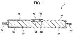
- Fig. 1 is a cross-sectional view of a vacuum insulation panel 1 manufactured by a vacuum insulation panel manufacturing device 2 of the present invention.
- Fig. 2 is an exploded view of the vacuum insulation panel 1.
- the vacuum insulation panel 1 is provided with a core member 10 made of an insulating material and a first metal plate (packaging member) 20 and a second metal plate 30 (packaging member) arranged so as to sandwich the core member 10.
- Bulging portions 21 and 31 are provided in the middle portions of the first metal plate 20 and the second metal plate 30.
- the first metal plate 20 and the second metal plate 30 are stacked in a state where the core member 10 is accommodated in the recessed portion that is on the inner surface sides of the bulging portions 21 and 31.
- Peripheral edge portions 40 (four sides) of the stacked first metal plate 20 and second metal plate 30 are seam welded.
- An evacuation port 32 which is a circular opening, is provided in the middle of the second metal plate 30.
- An annular backing member 50 is arranged inside the second metal plate 30 across the evacuation port 32, a circular sealing member 60 is arranged outside the second metal plate 30, and the evacuation port 32 is sealed as a result.
- the backing member 50, the second metal plate 30, and the sealing member 60 are laser welded as described later, and the inside of the vacuum insulation panel 1 is maintained in a vacuum state.
- the core member 10 is formed by organic fibers such as synthetic fibers and natural fibers or inorganic fibers such as glass fibers and rock wool, which are insulating materials, being laminated so as to have a predetermined thickness.
- the first metal plate 20 and the second metal plate 30 are formed in a rectangular shape slightly larger than the core member 10 in plain view and are arranged so as to cover the upper surface and the lower surface of the core member 10.
- a stainless steel plate excellent in strength and corrosion resistance is preferably used from the viewpoint of deformation resistance and appearance maintenance over a long period of time.
- the thicknesses of the first metal plate 20 and the second metal plate 30 are preferably 0.1 mm to 0.3 mm from the viewpoint of reducing the weight of the vacuum insulation panel 1 while suitably maintaining the vacuum state inside the vacuum insulation panel 1.
- the first metal plate 20 and the second metal plate 30 are provided with the bulging portions 21 and 31 for core member accommodation.
- the bulging portions 21 and 31 have a shape in which the respective inner surface sides of the first metal plate 20 and the second metal plate 30 are recessed in a shape corresponding to the core member 10 and bulge to the outer surface sides.
- the evacuation port 32 is provided in the middle of the bulging portion 31 of the second metal plate 30.
- the backing member 50 has an annular shape, and an opening portion 51 having the same diameter as the evacuation port 32 provided in the second metal plate 30 is provided in the middle of the backing member 50.
- the sealing member 60 has a disk shape and has the same diameter as the backing member 50.
- SUS 430 as a magnetic body is used as the backing member 50 and the sealing member 60.
- the backing member 50 may be another metal member without having to be limited to the magnetic body and the sealing member 60 may be another magnetic body.
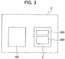
- Fig. 3 is a block diagram of the vacuum insulation panel manufacturing device 2.
- the vacuum insulation panel manufacturing device 2 is provided with a seam welding device 100 performing a seam welding step on the outer peripheries of the first metal plate 20 and the second metal plate 30 and a vacuum device 3 performing vacuum creation and sealing on the inside of a panel in a state where a vacuum is yet to be created inside with seam welding performed.
- the vacuum device 3 is provided with a vacuum suction unit 200 and a laser welding unit 300.
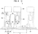
- Fig. 4 is a diagram illustrating the seam welding device 100
- Fig. 5 is a schematic perspective view of the seam welding device 100.
- the seam welding device 100 is provided with a plurality of lower electrodes 130, a plurality of upper electrodes 140, a plurality of upper electrode support members 150 supporting the plurality of upper electrodes 140, an upper electrode moving mechanism 160, a first inter-electrode distance variable mechanism 170, and a second inter-electrode distance variable mechanism 180.
- two lower electrodes 130, two upper electrodes 140, two upper electrode support members 150, two upper electrode moving mechanisms 160, and two first inter-electrode distance variable mechanisms 170 are provided.
- the lower electrode 130 is formed in a rail shape (block shape) and is arranged on a floor surface 101.
- the plurality of lower electrodes 130 extend in parallel to each other.
- two lower electrodes 130 are arranged.
- the lower electrode 130 is arranged on the floor surface 101 via the second inter-electrode distance variable mechanism 180 (described later) arranged on the floor surface 101.
- the upper electrode 140 is arranged above each lower electrode 130.
- the upper electrode 140 is formed in a disk shape and is arranged such that the circumferential direction (rotation direction) of the disk is along the direction in which the lower electrode 130 extends.
- the upper electrode support member 150 rotatably supports the upper electrode 140 in the direction in which the lower electrode 130 extends.
- the upper electrode support member 150 is arranged beside each upper electrode 140 and is provided with a shaft member 151 connected to the rotation center of the upper electrode 140 and extending in the horizontal direction and a main body portion 152 rotatably supporting the shaft member 151.
- the upper electrode moving mechanism 160 moves the upper electrode support member 150 in the direction in which the lower electrode 130 extends.
- the upper electrode moving mechanism 160 includes, for example, a rail member arranged above the upper electrode support member 150, extending in the same direction as the direction in which the lower electrode 130 extends, and supporting the upper electrode support member 150.
- the first inter-electrode distance variable mechanism 170 varies the distance between the lower electrode 130 and the upper electrode 140.
- the first inter-electrode distance variable mechanism 170 includes, for example, a piston rod 171 and a cylinder (not illustrated) advancing and retracting the piston rod 171 upwards and downwards.
- the lower end side of the piston rod 171 is connected to the upper electrode support member 150 and the upper end side of the piston rod 171 is connected to the upper electrode moving mechanism 160.
- the second inter-electrode distance variable mechanism 180 is interposed between the lower electrode 130 and a bottom surface and varies distances W between the plurality of lower electrodes 130 and between the plurality of upper electrodes 140.
- the second inter-electrode distance variable mechanism 180 is provided with a base 181 installed on the floor surface 101 and a fixed table 182 and a movable table 183 arranged on the upper surface of the base 181.
- the base 181 is fixed to the floor surface 101.
- the fixed table 182 is fixed to the upper surface of the base 181.
- the movable table 183 is installed so as to be slidable with respect to the base 181.
- one of the two lower electrodes 130 is fixed to the upper surface of the fixed table 182 and the other is fixed to the upper surface of the movable table 183.
- one of the two upper electrode moving mechanisms 160 and one of the two first inter-electrode distance variable mechanisms 170 are fixed to the upper surface of the fixed table 182 via a support frame 190 and the others are fixed to the upper surface of the movable table 183 via the support frame 190.
- the movable table 183 slides in a direction X, which is orthogonal to the direction in which the lower electrode 130 extends. As a result, it is possible to change the distance W between the two lower electrodes 130 and the distance W between the two upper electrodes.
- Fig. 6 is a diagram illustrating the vacuum device 3 of the vacuum insulation panel manufacturing device 2.
- the vacuum device 3 is provided with the vacuum suction unit 200 and the laser welding unit 300.
- a partial cross section is illustrated for easy understanding and the whole is not necessarily illustrated in cross section.
- the vacuum suction unit 200 is provided with a chamber 210 having an open bottom portion and a sealing member lifting mechanism 250 provided in the chamber 210.
- the chamber 210 has an open bottom portion (opening portion 211). On the outer periphery of the opening portion 211, a packing 217 is arranged over the entire circumference in the circumferential direction. Sealability is maintained and evacuation is possible by the packing 217 and the surface of the second metal plate 30 being brought into close contact with each other.
- a flange portion 212 extending to the outer diameter side is provided on the outer periphery of the bottom portion of the chamber 210.
- a pillar member 218 extending upwards is fixed to the outer periphery of the flange portion 212.
- two pillar members 218 are attached in bilateral symmetry. In the embodiment, however, the pillar members 218 are attached in three places evenly in the circumferential direction.
- the upper end of the pillar member 218 is fixed to an upper plate 219 holding the sealing member lifting mechanism 250.
- the upper plate 219 is annular and a circular upper plate opening portion 220 is provided in the middle portion of the upper plate 219.
- a window 213 is provided in the middle of the upper portion of the chamber 210, and quartz glass 214 is attached to the window 213.
- a chamber evacuation hole 215 is provided in a side portion of the chamber 210.
- a pipe 216 is connected to the chamber evacuation hole 215, and a vacuum pump (not illustrated) is connected to the pipe 216.
- the sealing member lifting mechanism 250 is provided with a holding plate 251 holding the sealing member 60, a support rod 253 supporting the holding plate 251 at the lower end, a lifting plate 255 to which the upper end of the support rod 253 is fixed, a lifting rod 258 screwed with the lifting plate 255, and a chain gear 260, a chain 261, and a rotary knob 262 rotating the lifting rod.
- the holding plate 251 has an annular shape with a hole 252 in the middle, and a magnet is attached inside.
- the sealing member 60 is made of a magnetic body, and thus the holding plate 251 is capable of holding the sealing member 60 with a magnetic force.
- the magnetic force of the holding plate 251 allows a worker to manually attach and detach the sealing member 60 from the holding plate 251 with ease.
- the force suctioned by vacuum is stronger than the magnetic force.
- the support rod 253 is attached to the holding plate 251 in three places along the circumference. In Fig. 3 , two support rods 253 are attached in bilateral symmetry. In the embodiment, however, the support rods 253 are attached in three places evenly in the circumferential direction. The support rod 253 extends upwards and has an upper end attached to the lifting plate 255.
- the support rod 253 is inserted, so as to be movable up and down while maintaining the airtight state of the chamber 210, in three places around the quartz glass 214 on the upper surface of the chamber 210.
- the lifting plate 255 has an annular shape with a hole 256 in the middle.
- a screw hole 257 is provided on the outer periphery side of the place where the support rod 253 supporting the holding plate 251 is fixed.
- the screw hole 257 is provided in two places in bilateral symmetry. In the embodiment, however, the screw holes 257 are attached in three places evenly in the circumferential direction.
- the lifting rod 258 having a threaded outer periphery is screwed into the screw hole 257 of the lifting plate.
- the lifting rod 258 is also provided in two places in bilateral symmetry. In the embodiment, however, the lifting rods 258 are provided in three places evenly in the circumferential direction.
- the lifting rod 258 passes through a hole 259 formed in the upper plate 219 and is held so as to be rotatable and so as to be incapable of moving up and down with respect to the upper plate 219.
- the chain gear 260 is attached to the upper end of the lifting rod 258.
- the chain 261 is bridged between the chain gears 260 of the three lifting rods 258.
- the chain 261 meshes with the gear of the chain gear 260.
- the rotary knob 262 is attached to the portion of one of the lifting rods 258 that is on the chain gear 260.
- a frame member 301 is arranged so as to cover the outside of the above-described vacuum suction unit 200.
- the frame member 301 is provided with a base member 302, a pillar member 303 extending upwards from the outer peripheral portion of the base member 302, and an upper frame portion 304 fixed to the upper end of the pillar member 303.
- the frame member 301 is fixed with the vacuum suction unit 200 by a connecting rod 306.
- the upper frame portion 304 moves up and down when the nut 307 is rotated in the clockwise direction or the counterclockwise direction. Possible as a result are fixing of the vacuum insulation panel 1 before sealing and opening of the vacuum insulation panel 1 after sealing.
- a circular hole 305 is provided in the middle of the upper frame portion 304.
- the laser welding unit 300 is arranged on the upper frame portion 304.
- the laser welding unit 300 is provided with a laser irradiation unit 310.
- the laser irradiation unit 310 is rotatable around an axis A of the vacuum device 3. In other words, the laser irradiation unit 310 is movable along a circumference with a predetermined diameter around the axis A.
- the upper plate opening portion 220, the window 213, the hole 252, and the quartz glass 214 are arranged around the axis A.
- the laser light that is emitted from the laser irradiation unit 310 rotatable around the axis A passes through the upper plate opening portion 220, the quartz glass 214, and the hole 252, and then the sealing member 60, the outer peripheral portion of the evacuation port 32 of the second metal plate 30, and the backing member 50 are welded.
- the diameters of the upper plate opening portion 220, the window 213, the hole 252, and the quartz glass 214 exceed the diameter of the evacuation port 32 by a certain width and are similar to, for example, the outer diameter of the backing member 50.
- the optical path of the laser light is not hindered during laser welding of the sealing member 60, the second metal plate 30, and the backing member 50 as described later.
- FIG. 7 is a diagram illustrating the method for manufacturing the vacuum insulation panel 1 by using the vacuum insulation panel manufacturing device 2.
- the method for manufacturing the vacuum insulation panel 1 includes an stacking step, a seam welding step, an evacuating step, a laser welding step, and a cutting step.
- Fig. 7A is a diagram illustrating the stacking step.
- the first metal plate 20 in which the bulging portion 21 is formed is arranged such that the bulging portion 21 faces downwards, and the core member 10 is accommodated in the recessed portion of the upper surface of the first metal plate 20.
- the backing member 50 is placed on the core member 10.
- the backing member 50 is arranged so as to be positioned substantially in the middle of the core member 10.
- the second metal plate 30 in which the bulging portion 31 is formed is stacked on the first metal plate 20, the core member 10, and the backing member 50 such that the bulging portion 31 faces upwards.
- a laminated body 1A is formed as a result.
- Fig. 7B is a diagram illustrating the seam welding step.
- seam welding is performed on the edge portions (four sides) of the first metal plate 20 and the second metal plate 30 in the laminated body 1A manufactured in the stacking step.
- the edge portions are parts outside the bulging portions 21 and 31, and the core member 10 is not included in the edge portions.
- This seam welding step is performed in the atmosphere.
- the seam welding is performed by the seam welding device 100 illustrated in Figs. 4 and 5 .
- the laminated body 1A manufactured in the stacking step is set in the seam welding device 100.
- the movable table 183 in Fig. 4 is slid until the distance between the two lower electrodes 130 matches the distance between two sides L1 (illustrated in Fig. 5 ) to be seam welded.
- the laminated body 1A is arranged such that the two sides L1 to be seam welded are positioned on the upper surface of the lower electrode 130.
- the two sides L1 are seam welded by the seam welding device 100.
- the two upper electrodes 140 are lowered by the first inter-electrode distance variable mechanism 170 and the first metal plate 20 and the second metal plate 30 are sandwiched between the upper electrodes 140 and the lower electrodes 130.
- the first metal plate 20 and the second metal plate 30 are seam welded while the upper electrode moving mechanism 160 simultaneously rotates and moves the two upper electrodes 140 in the direction in which the lower electrode 130 extends.
- the two facing sides L1 of the first metal plate 20 and the second metal plate 30 are seam welded at the same time.
- the seam welding device 100 seam welds two sides L2, which are orthogonal to the side LI, similarly to the above L1. At this time, the welding line of the side L1 and the welding line of the side L2 are allowed to intersect.
- the two facing sides L1 of the first metal plate 20 and the second metal plate 30 and the facing sides L2 orthogonal to the sides L1 are seam welded.
- Fig. 7C is a diagram illustrating the evacuating step.
- the sealing member 60 is mounted on the holding plate 251.
- the holding plate 251 is positioned above the opening portion 211 of the chamber 210.
- the center of the sealing member 60 is allowed to come to the axis A.
- the sealing member 60 which is made of a magnetic body, can be easily attached and detached by the magnetic force of the holding plate 251.
- the panel 1B resulting from the seam welding step and not evacuated inside is arranged under the chamber 210 on the base member 302 of the frame member 301. Then, fixing is performed by means of the frame member 301 and tightening of the nut 307. At this time, the center of the evacuation port 32 of the panel 1B is set so as to be on the axis A of the device, and fixing is performed such that the panel 1B is pressed down with uniformity.
- sealability with respect to the upper surface of the second metal plate 30 of the panel 1B is excellent as the packing 217 is attached to the bottom portion of the chamber 210.
- the vacuum pump (not illustrated) that is connected to the chamber evacuation hole 215 of the chamber 210 is operated. Evacuation is performed to the target vacuum degree in the chamber 210 or less.
- the sealing member 60 when the evacuation is performed, the sealing member 60 may be allowed to approach the evacuation port 32 by being temporarily lowered and the evacuation may be initiated in that state. At the beginning of the evacuation, turbulence may occur and the glass wool or the like of the core member 10 may be scattered. In the initial stage of the evacuation that may entail turbulence as described above, the sealing member 60 and the evacuation port 32 are allowed to be in proximity to each other in terms of distance, and thus airflow stabilization is achieved and the possibility of such content scattering and the like is reduced. After the airflow is stabilized, the sealing member 60 is raised so as not to hinder the evacuation.
- the distance between the evacuation port 32 and the sealing member 60 at the beginning of the evacuation is preferably 0.5 mm to 3.0 mm.
- the sealing member 60 is lowered and the evacuation port 32 is blocked as illustrated in Fig. 7D .
- the lowering of the sealing member 60 is performed as follows.
- the rotary knob 262 illustrated in Fig. 6 is rotated. Then, the chain 261 transmits a rotational force, and each of the chain gears 260 rotates. Once the chain gears 260 rotate, the lifting rods 258 connected to the chain gears 260 rotate as well, and the lifting plate 255 screwed with the screw portions of the lifting rods 258 moves up and down. Once the lifting plate 255 is lowered, the support rod 253 supported by the lifting plate 255 and the holding plate 251 supported by the lower end of the support rod 253 are lowered, and the sealing member 60 held by the holding plate 251 is lowered as well.
- the sealing member 60 is lowered in this manner and pressed toward the evacuation port 32 side.
- the second metal plate 30 is sandwiched between the backing member 50 inserted in the panel 1B and the lowered sealing member 60. Accordingly, the part where the lowered sealing member 60, the second metal plate 30, and the backing member 50 are stacked in three sheets is restrained without a gap.
- the laser irradiation unit 310 of the laser welding unit 300 emits laser to the part where the sealing member 60, the second metal plate 30, and the backing member 50 are stacked in three sheets.
- the laser emission is performed over the entire circumference around the evacuation port 32 by the laser irradiation unit 310 being rotated.
- the backing member 50 is arranged besides the lowered sealing member 60 and the second metal plate 30.
- the second metal plate 30 is thin. Accordingly, there is a possibility of melting down in a case where only the sealing member 60 and the second metal plate 30 are used during the laser welding. In the present embodiment, however, the possibility of melting down is low since the backing member 50 is arranged as well.
- the part where the sealing member 60, the second metal plate 30, and the backing member 50 are stacked in three sheets is circumferentially welded by the laser light emitted by the laser irradiation unit 310, and thus the internal space in which the core member 10 sandwiched by the first metal plate 20 and the second metal plate 30 is arranged can be completely sealed.
- the vacuum insulation panel 1 is completed as a result.
- the vacuum is released after the part where the lowered sealing member 60, the second metal plate 30, and the backing member 50 are stacked in three sheets is laser welded.
- the holding plate 251 is raised by the rotary knob 262 being rotated in the direction that is opposite to the lowering direction.
- the vacuum insulation panel 1 is removed from the vacuum device 3, by the nut 307 of the frame member 301 being loosened, with the internal space sealed through the laser welding step. Then, the surplus part in the outer peripheral portion of the vacuum insulation panel 1 is cut and the vacuum insulation panel 1 is completed.
- the vacuum insulation panel 1 was actually manufactured by means of the vacuum insulation panel manufacturing device 2.
- a glass wool with a basis weight of approximately 1,200 g/m 2 was used and an object was used that has a dimension capable of filling the inner surface side of the bulging portion to be described later without gaps when the first metal plate 20 and the second metal plate 30 are stacked.
- a steel plate of SUS 304 was used as the first metal plate 20 and the second metal plate 30.
- the dimensions are 220 mm ⁇ 220 mm ⁇ 0.1 mm.
- the bulging portions 21 and 31 of 190 mm ⁇ 190 mm ⁇ 5.0 mm were produced by press molding in the first metal plate 20 and the second metal plate 30, respectively.
- the evacuation port 32 in the middle of the bulging portion 31 of the second metal plate 30 has a diameter of 20 mm.
- SUS 430 as a magnetic body was used for the backing member 50 and the sealing member 60.
- the dimensions are 0.3 mm in thickness and 40 mm in outer diameter dimension.
- the opening portion 51 of the backing member 50 has a diameter of 20 mm as in the case of the evacuation port 32 provided in the second metal plate 30.
- a single phase AC-type device was used as the seam welding device 100.
- the upper electrode which is 100 mm in diameter and 4 mm in thickness, has a disk shape with a flat electrode tip portion.
- the lower electrode has a block shape and has a thickness of 4 mm, a height of 50 mm, a length of 250 mm, and an electrode tip portion curvature of 20 R.
- the welding conditions are an applied pressure of 250 N, a welding speed of 1 m/min, a welding current of 1.6 kA, and an energization time ON/OFF ratio of 3 ms/2 ms.
- the outer diameter of the opening portion 211 of the chamber 210 is approximately 220 mm, and the packing 217 is a silicone rubber packing with a thickness of 20 mm.
- Used as the quartz glass 214 was a circular quartz glass with an outer diameter of 40 mm through which a laser beam with a wavelength of 1 ⁇ m is capable of passing.
- a fiber laser welding machine manufactured by IPG was used as the laser welding unit 300, and the welding conditions are a welding speed of 10 m/min, an output of 700 W, a laser spot diameter of ⁇ 0.2 mm, and pulse-type laser oscillation.
- the vacuum insulation panel 1 was manufactured and its performance was evaluated.
- a thermal conductivity measuring device (model: FOX200) manufactured by EKO Instruments Co., Ltd. was used for thermal conductivity measurement and evaluation under a condition that the middle portion of the vacuum insulation panel 1 has an average temperature of 25°C.
- the laser welding does not require heating of a welding spot such as brazing, and irradiation can be performed from the outside of the chamber 210 through the quartz glass 214. Accordingly, a heating unit or the like does not have to be arranged in the chamber 210.
- the chamber 210 can be reduced in size, and the manufacturing cost of the vacuum insulation panel 1 can be reduced.
- the backing member 50 is arranged inside the part of the evacuation port 32 of the second metal plate 30. Accordingly, the possibility of melting down attributable to laser welding is low, and laser welding to the part where the backing member 50 is arranged becomes possible. Therefore, sealing by the sealing member 60 using the laser welding of the evacuation port 32 becomes possible.
Landscapes
- Engineering & Computer Science (AREA)
- Physics & Mathematics (AREA)
- Optics & Photonics (AREA)
- Mechanical Engineering (AREA)
- Plasma & Fusion (AREA)
- General Engineering & Computer Science (AREA)
- Chemical & Material Sciences (AREA)
- Combustion & Propulsion (AREA)
- Thermal Sciences (AREA)
- Laser Beam Processing (AREA)
- Thermal Insulation (AREA)
- Joining Of Glass To Other Materials (AREA)
Abstract
Description
- The present invention relates to a vacuum insulation panel manufacturing device suitably used for a refrigerator, a cold storage, a hot storage, a heat insulating wall of a house or the like, and so on.
- In recent years, development of energy-saving products and energy-saving techniques is in progress in every industry with regard to electric power shortage and so on. Vacuum insulation panels are products developed as one of energy-saving measures. At present, the panels are widely adopted as a heat insulating material for refrigerators, vending machines, and the like and for heat insulating performance enhancement and electric power consumption reduction. Also in progress is examination for application as a heat insulating material for houses. In general, existing vacuum insulation panels have a structure in which a core member such as glass wool is heat sealed with an aluminum laminate film.
- In a vacuum insulation panel heat sealed with an aluminum laminate film, moisture permeation from a heat seal portion results in a decrease in the degree of vacuum, and enclosure with an adsorbent such as activated carbon and zeolite is performed in this regard. Even so, a problem arises as the heat insulating performance is halved in seven to eight years. Desired in this regard is development of a vacuum insulation panel capable of maintaining its heat insulating properties for a long time. Developed as a vacuum insulation panel having long-term heat insulation properties is a vacuum insulation panel that is evacuated inside and has a stainless steel-based end portion welded in a state where a core member such as glass wool is wrapped with a thin metal plate such as a stainless steel plate.
-
Patent Document 1 discloses a device for manufacturing such vacuum insulation panels. In the device, a heat insulating material is arranged in the space that is formed by an inner plate body and an outer plate body provided with an evacuation port, a laminated body is prepared in which the peripheral edge portions of the outer and inner plate bodies are welded, a sealing member is placed on the wax that is arranged around the evacuation port, the laminated body is arranged in a chamber, vacuum suctioning is performed from the evacuation port by a vacuum suction unit, the wax is melted by heating of the laminated body, and the evacuation port is sealed by the sealing member. - Patent Document 1: Japanese Patent No.
4365736 - In the manufacturing device disclosed in
Patent Document 1, evacuation and brazing are performed in the chamber. Accordingly, the chamber is required into which the entire laminated body of the outer and inner plate bodies and the heat insulating material is put. In addition, a heating unit in the chamber is required since brazing is performed in the chamber. As a result, the size of the vacuum insulation panel manufacturing device increases to entail costs. - An object of the present invention is to provide a miniaturizable vacuum insulation panel manufacturing device.
- In the vacuum insulation panel manufacturing device according to the present invention, a vacuum insulation panel is manufactured by wrapping an insulating core member with a packaging member in which an evacuation port is provided, applying a vacuum to evacuate inside of the packaging member from the evacuation port, and sealing the evacuation port with a sealing member. The vacuum insulation panel manufacturing device includes a chamber with an opened bottom, a chamber evacuation hole provided in the chamber, a quartz glass window unit provided in the top of the chamber, a holding unit which can hold the sealing member, a lifting mechanism which raises/lowers the holding unit, a frame member which holds and raises/lowers the chamber, and a laser welding unit provided outside of the chamber.
- The holding unit may include a magnet and be capable of holding the sealing member as a magnetic body by using a magnetic force on an evacuation port side surface of the holding unit.
- The holding unit may be capable of pressing the sealing member to a region covering the evacuation port of the packaging member.
- A seal member may be attached to an outer periphery of the opening of the chamber.
- A laser emitting unit of the laser welding unit may be rotatable around an axis.
- According to the present invention, a miniaturizable vacuum insulation panel manufacturing device can be provided.
-
-
Fig. 1 is a cross-sectional view of avacuum insulation panel 1. -
Fig. 2 is an exploded view of thevacuum insulation panel 1. -
Fig. 3 is a block diagram of a vacuum insulationpanel manufacturing device 2 manufacturing thevacuum insulation panel 1. -
Fig. 4 is a diagram illustrating aseam welding device 100. -
Fig. 5 is a schematic perspective view of theseam welding device 100. -
Fig. 6 is a diagram illustrating avacuum device 3 of the vacuum insulationpanel manufacturing device 2. -
Figs. 7 are diagrams illustrating a method for manufacturing thevacuum insulation panel 1 by using the vacuum insulationpanel manufacturing device 2. - Hereinafter, a preferred embodiment of the present invention will be described with reference to accompanying drawings.
Fig. 1 is a cross-sectional view of avacuum insulation panel 1 manufactured by a vacuum insulationpanel manufacturing device 2 of the present invention.Fig. 2 is an exploded view of thevacuum insulation panel 1. - The
vacuum insulation panel 1 is provided with acore member 10 made of an insulating material and a first metal plate (packaging member) 20 and a second metal plate 30 (packaging member) arranged so as to sandwich thecore member 10. - Bulging
portions first metal plate 20 and thesecond metal plate 30. Thefirst metal plate 20 and thesecond metal plate 30 are stacked in a state where thecore member 10 is accommodated in the recessed portion that is on the inner surface sides of the bulgingportions - Peripheral edge portions 40 (four sides) of the stacked
first metal plate 20 andsecond metal plate 30 are seam welded. - An
evacuation port 32, which is a circular opening, is provided in the middle of thesecond metal plate 30. Anannular backing member 50 is arranged inside thesecond metal plate 30 across theevacuation port 32, acircular sealing member 60 is arranged outside thesecond metal plate 30, and theevacuation port 32 is sealed as a result. - The
backing member 50, thesecond metal plate 30, and the sealingmember 60 are laser welded as described later, and the inside of thevacuum insulation panel 1 is maintained in a vacuum state. - The
core member 10 is formed by organic fibers such as synthetic fibers and natural fibers or inorganic fibers such as glass fibers and rock wool, which are insulating materials, being laminated so as to have a predetermined thickness. - The
first metal plate 20 and thesecond metal plate 30 are formed in a rectangular shape slightly larger than thecore member 10 in plain view and are arranged so as to cover the upper surface and the lower surface of thecore member 10. - Although various metal plates such as an aluminum alloy plate and a stainless steel plate can be used as the material of the
first metal plate 20 and thesecond metal plate 30, a stainless steel plate excellent in strength and corrosion resistance is preferably used from the viewpoint of deformation resistance and appearance maintenance over a long period of time. - The thicknesses of the
first metal plate 20 and thesecond metal plate 30 are preferably 0.1 mm to 0.3 mm from the viewpoint of reducing the weight of thevacuum insulation panel 1 while suitably maintaining the vacuum state inside thevacuum insulation panel 1. - The
first metal plate 20 and thesecond metal plate 30 are provided with the bulgingportions portions first metal plate 20 and thesecond metal plate 30 are recessed in a shape corresponding to thecore member 10 and bulge to the outer surface sides. - The
evacuation port 32 is provided in the middle of the bulgingportion 31 of thesecond metal plate 30. - The
backing member 50 has an annular shape, and anopening portion 51 having the same diameter as theevacuation port 32 provided in thesecond metal plate 30 is provided in the middle of thebacking member 50. The sealingmember 60 has a disk shape and has the same diameter as thebacking member 50. In the embodiment, SUS 430 as a magnetic body is used as thebacking member 50 and the sealingmember 60. However, the present invention is not limited thereto, and the backingmember 50 may be another metal member without having to be limited to the magnetic body and the sealingmember 60 may be another magnetic body. - Next, the vacuum insulation
panel manufacturing device 2 of the embodiment for manufacturing thevacuum insulation panel 1 will be described.Fig. 3 is a block diagram of the vacuum insulationpanel manufacturing device 2. The vacuum insulationpanel manufacturing device 2 is provided with aseam welding device 100 performing a seam welding step on the outer peripheries of thefirst metal plate 20 and thesecond metal plate 30 and avacuum device 3 performing vacuum creation and sealing on the inside of a panel in a state where a vacuum is yet to be created inside with seam welding performed. Thevacuum device 3 is provided with avacuum suction unit 200 and alaser welding unit 300. - The
seam welding device 100 will be described first.Fig. 4 is a diagram illustrating theseam welding device 100, andFig. 5 is a schematic perspective view of theseam welding device 100. - The
seam welding device 100 is provided with a plurality oflower electrodes 130, a plurality ofupper electrodes 140, a plurality of upperelectrode support members 150 supporting the plurality ofupper electrodes 140, an upperelectrode moving mechanism 160, a first inter-electrode distancevariable mechanism 170, and a second inter-electrode distancevariable mechanism 180. - In the present embodiment, two
lower electrodes 130, twoupper electrodes 140, two upperelectrode support members 150, two upperelectrode moving mechanisms 160, and two first inter-electrode distancevariable mechanisms 170 are provided. - As illustrated in
Figs. 4 and5 , thelower electrode 130 is formed in a rail shape (block shape) and is arranged on afloor surface 101. The plurality oflower electrodes 130 extend in parallel to each other. In the present embodiment, twolower electrodes 130 are arranged. In the present embodiment, thelower electrode 130 is arranged on thefloor surface 101 via the second inter-electrode distance variable mechanism 180 (described later) arranged on thefloor surface 101. - The
upper electrode 140 is arranged above eachlower electrode 130. Theupper electrode 140 is formed in a disk shape and is arranged such that the circumferential direction (rotation direction) of the disk is along the direction in which thelower electrode 130 extends. - The upper
electrode support member 150 rotatably supports theupper electrode 140 in the direction in which thelower electrode 130 extends. In the present embodiment, the upperelectrode support member 150 is arranged beside eachupper electrode 140 and is provided with ashaft member 151 connected to the rotation center of theupper electrode 140 and extending in the horizontal direction and amain body portion 152 rotatably supporting theshaft member 151. - The upper
electrode moving mechanism 160 moves the upperelectrode support member 150 in the direction in which thelower electrode 130 extends. The upperelectrode moving mechanism 160 includes, for example, a rail member arranged above the upperelectrode support member 150, extending in the same direction as the direction in which thelower electrode 130 extends, and supporting the upperelectrode support member 150. - The first inter-electrode distance
variable mechanism 170 varies the distance between thelower electrode 130 and theupper electrode 140. The first inter-electrode distancevariable mechanism 170 includes, for example, apiston rod 171 and a cylinder (not illustrated) advancing and retracting thepiston rod 171 upwards and downwards. The lower end side of thepiston rod 171 is connected to the upperelectrode support member 150 and the upper end side of thepiston rod 171 is connected to the upperelectrode moving mechanism 160. - The second inter-electrode distance
variable mechanism 180 is interposed between thelower electrode 130 and a bottom surface and varies distances W between the plurality oflower electrodes 130 and between the plurality ofupper electrodes 140. The second inter-electrode distancevariable mechanism 180 is provided with a base 181 installed on thefloor surface 101 and a fixed table 182 and a movable table 183 arranged on the upper surface of thebase 181. - The
base 181 is fixed to thefloor surface 101. The fixed table 182 is fixed to the upper surface of thebase 181. The movable table 183 is installed so as to be slidable with respect to thebase 181. - In the present embodiment, one of the two
lower electrodes 130 is fixed to the upper surface of the fixed table 182 and the other is fixed to the upper surface of the movable table 183. In addition, one of the two upperelectrode moving mechanisms 160 and one of the two first inter-electrode distancevariable mechanisms 170 are fixed to the upper surface of the fixed table 182 via asupport frame 190 and the others are fixed to the upper surface of the movable table 183 via thesupport frame 190. - The movable table 183 slides in a direction X, which is orthogonal to the direction in which the
lower electrode 130 extends. As a result, it is possible to change the distance W between the twolower electrodes 130 and the distance W between the two upper electrodes. - The
vacuum device 3 of the vacuum insulationpanel manufacturing device 2 will be described below.Fig. 6 is a diagram illustrating thevacuum device 3 of the vacuum insulationpanel manufacturing device 2. Thevacuum device 3 is provided with thevacuum suction unit 200 and thelaser welding unit 300. In the drawing, a partial cross section is illustrated for easy understanding and the whole is not necessarily illustrated in cross section. - The
vacuum suction unit 200 is provided with achamber 210 having an open bottom portion and a sealingmember lifting mechanism 250 provided in thechamber 210. - The
chamber 210 has an open bottom portion (opening portion 211). On the outer periphery of theopening portion 211, a packing 217 is arranged over the entire circumference in the circumferential direction. Sealability is maintained and evacuation is possible by the packing 217 and the surface of thesecond metal plate 30 being brought into close contact with each other. - A
flange portion 212 extending to the outer diameter side is provided on the outer periphery of the bottom portion of thechamber 210. Apillar member 218 extending upwards is fixed to the outer periphery of theflange portion 212. InFig. 3 , twopillar members 218 are attached in bilateral symmetry. In the embodiment, however, thepillar members 218 are attached in three places evenly in the circumferential direction. - The upper end of the
pillar member 218 is fixed to anupper plate 219 holding the sealingmember lifting mechanism 250. Theupper plate 219 is annular and a circular upperplate opening portion 220 is provided in the middle portion of theupper plate 219. - A
window 213 is provided in the middle of the upper portion of thechamber 210, andquartz glass 214 is attached to thewindow 213. Achamber evacuation hole 215 is provided in a side portion of thechamber 210. Apipe 216 is connected to thechamber evacuation hole 215, and a vacuum pump (not illustrated) is connected to thepipe 216. - The sealing
member lifting mechanism 250 is provided with a holdingplate 251 holding the sealingmember 60, asupport rod 253 supporting the holdingplate 251 at the lower end, alifting plate 255 to which the upper end of thesupport rod 253 is fixed, a liftingrod 258 screwed with the liftingplate 255, and achain gear 260, achain 261, and arotary knob 262 rotating the lifting rod. - The holding
plate 251 has an annular shape with ahole 252 in the middle, and a magnet is attached inside. As described above, the sealingmember 60 is made of a magnetic body, and thus the holdingplate 251 is capable of holding the sealingmember 60 with a magnetic force. - Incidentally, the magnetic force of the holding
plate 251 allows a worker to manually attach and detach the sealingmember 60 from the holdingplate 251 with ease. During sealing of theevacuation port 32 of thesecond metal plate 30 as described later, the force suctioned by vacuum is stronger than the magnetic force. Once the holdingplate 251 is raised in a vacuum-suctioned state, the sealingmember 60 is separated from the holdingplate 251. - The
support rod 253 is attached to the holdingplate 251 in three places along the circumference. InFig. 3 , twosupport rods 253 are attached in bilateral symmetry. In the embodiment, however, thesupport rods 253 are attached in three places evenly in the circumferential direction. Thesupport rod 253 extends upwards and has an upper end attached to thelifting plate 255. - The
support rod 253 is inserted, so as to be movable up and down while maintaining the airtight state of thechamber 210, in three places around thequartz glass 214 on the upper surface of thechamber 210. - The lifting
plate 255 has an annular shape with ahole 256 in the middle. Ascrew hole 257 is provided on the outer periphery side of the place where thesupport rod 253 supporting the holdingplate 251 is fixed. - In
Fig. 3 , thescrew hole 257 is provided in two places in bilateral symmetry. In the embodiment, however, the screw holes 257 are attached in three places evenly in the circumferential direction. - The lifting
rod 258 having a threaded outer periphery is screwed into thescrew hole 257 of the lifting plate. InFig. 3 , the liftingrod 258 is also provided in two places in bilateral symmetry. In the embodiment, however, the liftingrods 258 are provided in three places evenly in the circumferential direction. - The lifting
rod 258 passes through ahole 259 formed in theupper plate 219 and is held so as to be rotatable and so as to be incapable of moving up and down with respect to theupper plate 219. - The
chain gear 260 is attached to the upper end of the liftingrod 258. Thechain 261 is bridged between the chain gears 260 of the three liftingrods 258. Thechain 261 meshes with the gear of thechain gear 260. Therotary knob 262 is attached to the portion of one of the liftingrods 258 that is on thechain gear 260. - A
frame member 301 is arranged so as to cover the outside of the above-describedvacuum suction unit 200. Theframe member 301 is provided with abase member 302, apillar member 303 extending upwards from the outer peripheral portion of thebase member 302, and anupper frame portion 304 fixed to the upper end of thepillar member 303. Theframe member 301 is fixed with thevacuum suction unit 200 by a connectingrod 306. - By the action of a
nut 307 and aspring 308 fixing theupper frame portion 304 and thepillar member 303, theupper frame portion 304 moves up and down when thenut 307 is rotated in the clockwise direction or the counterclockwise direction. Possible as a result are fixing of thevacuum insulation panel 1 before sealing and opening of thevacuum insulation panel 1 after sealing. Acircular hole 305 is provided in the middle of theupper frame portion 304. Thelaser welding unit 300 is arranged on theupper frame portion 304. - The
laser welding unit 300 is provided with alaser irradiation unit 310. Thelaser irradiation unit 310 is rotatable around an axis A of thevacuum device 3. In other words, thelaser irradiation unit 310 is movable along a circumference with a predetermined diameter around the axis A. - The upper
plate opening portion 220, thewindow 213, thehole 252, and thequartz glass 214 are arranged around the axis A. The laser light that is emitted from thelaser irradiation unit 310 rotatable around the axis A passes through the upperplate opening portion 220, thequartz glass 214, and thehole 252, and then the sealingmember 60, the outer peripheral portion of theevacuation port 32 of thesecond metal plate 30, and the backingmember 50 are welded. - Incidentally, the diameters of the upper
plate opening portion 220, thewindow 213, thehole 252, and thequartz glass 214 exceed the diameter of theevacuation port 32 by a certain width and are similar to, for example, the outer diameter of the backingmember 50. As a result, the optical path of the laser light is not hindered during laser welding of the sealingmember 60, thesecond metal plate 30, and the backingmember 50 as described later. - A method for manufacturing the
vacuum insulation panel 1 by using the vacuum insulationpanel manufacturing device 2 of the embodiment will be described below.Fig. 7 is a diagram illustrating the method for manufacturing thevacuum insulation panel 1 by using the vacuum insulationpanel manufacturing device 2. - The method for manufacturing the
vacuum insulation panel 1 includes an stacking step, a seam welding step, an evacuating step, a laser welding step, and a cutting step. -
Fig. 7A is a diagram illustrating the stacking step. - First, the
first metal plate 20 in which the bulgingportion 21 is formed is arranged such that the bulgingportion 21 faces downwards, and thecore member 10 is accommodated in the recessed portion of the upper surface of thefirst metal plate 20. - The backing
member 50 is placed on thecore member 10. The backingmember 50 is arranged so as to be positioned substantially in the middle of thecore member 10. - Subsequently, the
second metal plate 30 in which the bulgingportion 31 is formed is stacked on thefirst metal plate 20, thecore member 10, and the backingmember 50 such that the bulgingportion 31 faces upwards. Alaminated body 1A is formed as a result. - At this time, adjustment is performed such that the opening
portion 51 of the backingmember 50 and theevacuation port 32 of thesecond metal plate 30 are aligned. -
Fig. 7B is a diagram illustrating the seam welding step. In the seam welding step, seam welding is performed on the edge portions (four sides) of thefirst metal plate 20 and thesecond metal plate 30 in thelaminated body 1A manufactured in the stacking step. The edge portions are parts outside the bulgingportions core member 10 is not included in the edge portions. This seam welding step is performed in the atmosphere. - The seam welding is performed by the
seam welding device 100 illustrated inFigs. 4 and5 . - First, the
laminated body 1A manufactured in the stacking step is set in theseam welding device 100. - Specifically, the movable table 183 in
Fig. 4 is slid until the distance between the twolower electrodes 130 matches the distance between two sides L1 (illustrated inFig. 5 ) to be seam welded. - Then, the
laminated body 1A is arranged such that the two sides L1 to be seam welded are positioned on the upper surface of thelower electrode 130. - Then, the two sides L1 are seam welded by the
seam welding device 100. - Specifically, first, the two
upper electrodes 140 are lowered by the first inter-electrode distancevariable mechanism 170 and thefirst metal plate 20 and thesecond metal plate 30 are sandwiched between theupper electrodes 140 and thelower electrodes 130. - The
first metal plate 20 and thesecond metal plate 30 are seam welded while the upperelectrode moving mechanism 160 simultaneously rotates and moves the twoupper electrodes 140 in the direction in which thelower electrode 130 extends. - As a result, the two facing sides L1 of the
first metal plate 20 and thesecond metal plate 30 are seam welded at the same time. - Next, the
seam welding device 100 seam welds two sides L2, which are orthogonal to the side LI, similarly to the above L1. At this time, the welding line of the side L1 and the welding line of the side L2 are allowed to intersect. - As a result, the two facing sides L1 of the
first metal plate 20 and thesecond metal plate 30 and the facing sides L2 orthogonal to the sides L1 are seam welded. - As a result of the above seam welding step, a
panel 1B that is not evacuated inside is manufactured. -
Fig. 7C is a diagram illustrating the evacuating step. - First, the sealing
member 60 is mounted on the holdingplate 251. At this time, the holdingplate 251 is positioned above theopening portion 211 of thechamber 210. In addition, the center of the sealingmember 60 is allowed to come to the axis A. At this time, the sealingmember 60, which is made of a magnetic body, can be easily attached and detached by the magnetic force of the holdingplate 251. - The
panel 1B resulting from the seam welding step and not evacuated inside is arranged under thechamber 210 on thebase member 302 of theframe member 301. Then, fixing is performed by means of theframe member 301 and tightening of thenut 307. At this time, the center of theevacuation port 32 of thepanel 1B is set so as to be on the axis A of the device, and fixing is performed such that thepanel 1B is pressed down with uniformity. - At this time, sealability with respect to the upper surface of the
second metal plate 30 of thepanel 1B is excellent as the packing 217 is attached to the bottom portion of thechamber 210. - The vacuum pump (not illustrated) that is connected to the
chamber evacuation hole 215 of thechamber 210 is operated. Evacuation is performed to the target vacuum degree in thechamber 210 or less. - Incidentally, when the evacuation is performed, the sealing
member 60 may be allowed to approach theevacuation port 32 by being temporarily lowered and the evacuation may be initiated in that state. At the beginning of the evacuation, turbulence may occur and the glass wool or the like of thecore member 10 may be scattered. In the initial stage of the evacuation that may entail turbulence as described above, the sealingmember 60 and theevacuation port 32 are allowed to be in proximity to each other in terms of distance, and thus airflow stabilization is achieved and the possibility of such content scattering and the like is reduced. After the airflow is stabilized, the sealingmember 60 is raised so as not to hinder the evacuation. - From the viewpoint of preventing glass wool scattering attributable to turbulence, the distance between the
evacuation port 32 and the sealingmember 60 at the beginning of the evacuation is preferably 0.5 mm to 3.0 mm. - After the target vacuum degree is reached, the sealing
member 60 is lowered and theevacuation port 32 is blocked as illustrated inFig. 7D . Here, the lowering of the sealingmember 60 is performed as follows. - The
rotary knob 262 illustrated inFig. 6 is rotated. Then, thechain 261 transmits a rotational force, and each of the chain gears 260 rotates. Once the chain gears 260 rotate, the liftingrods 258 connected to the chain gears 260 rotate as well, and thelifting plate 255 screwed with the screw portions of the liftingrods 258 moves up and down. Once the liftingplate 255 is lowered, thesupport rod 253 supported by the liftingplate 255 and the holdingplate 251 supported by the lower end of thesupport rod 253 are lowered, and the sealingmember 60 held by the holdingplate 251 is lowered as well. - The sealing
member 60 is lowered in this manner and pressed toward theevacuation port 32 side. As a result of this pressing, thesecond metal plate 30 is sandwiched between the backingmember 50 inserted in thepanel 1B and the lowered sealingmember 60. Accordingly, the part where the lowered sealingmember 60, thesecond metal plate 30, and the backingmember 50 are stacked in three sheets is restrained without a gap. - Subsequently, the
laser irradiation unit 310 of thelaser welding unit 300 emits laser to the part where the sealingmember 60, thesecond metal plate 30, and the backingmember 50 are stacked in three sheets. The laser emission is performed over the entire circumference around theevacuation port 32 by thelaser irradiation unit 310 being rotated. - Here, the backing
member 50 is arranged besides the lowered sealingmember 60 and thesecond metal plate 30. Thesecond metal plate 30 is thin. Accordingly, there is a possibility of melting down in a case where only the sealingmember 60 and thesecond metal plate 30 are used during the laser welding. In the present embodiment, however, the possibility of melting down is low since the backingmember 50 is arranged as well. - The part where the sealing
member 60, thesecond metal plate 30, and the backingmember 50 are stacked in three sheets is circumferentially welded by the laser light emitted by thelaser irradiation unit 310, and thus the internal space in which thecore member 10 sandwiched by thefirst metal plate 20 and thesecond metal plate 30 is arranged can be completely sealed. Thevacuum insulation panel 1 is completed as a result. - The vacuum is released after the part where the lowered sealing
member 60, thesecond metal plate 30, and the backingmember 50 are stacked in three sheets is laser welded. The holdingplate 251 is raised by therotary knob 262 being rotated in the direction that is opposite to the lowering direction. - In the cutting step, the
vacuum insulation panel 1 is removed from thevacuum device 3, by thenut 307 of theframe member 301 being loosened, with the internal space sealed through the laser welding step. Then, the surplus part in the outer peripheral portion of thevacuum insulation panel 1 is cut and thevacuum insulation panel 1 is completed. - Under the following conditions, the
vacuum insulation panel 1 was actually manufactured by means of the vacuum insulationpanel manufacturing device 2. - As the
core member 10, a glass wool with a basis weight of approximately 1,200 g/m2 was used and an object was used that has a dimension capable of filling the inner surface side of the bulging portion to be described later without gaps when thefirst metal plate 20 and thesecond metal plate 30 are stacked. - A steel plate of
SUS 304 was used as thefirst metal plate 20 and thesecond metal plate 30. The dimensions are 220 mm × 220 mm × 0.1 mm. Then, the bulgingportions first metal plate 20 and thesecond metal plate 30, respectively. - The
evacuation port 32 in the middle of the bulgingportion 31 of thesecond metal plate 30 has a diameter of 20 mm. - SUS 430 as a magnetic body was used for the backing
member 50 and the sealingmember 60. The dimensions are 0.3 mm in thickness and 40 mm in outer diameter dimension. The openingportion 51 of the backingmember 50 has a diameter of 20 mm as in the case of theevacuation port 32 provided in thesecond metal plate 30. - A single phase AC-type device was used as the
seam welding device 100. The upper electrode, which is 100 mm in diameter and 4 mm in thickness, has a disk shape with a flat electrode tip portion. The lower electrode has a block shape and has a thickness of 4 mm, a height of 50 mm, a length of 250 mm, and an electrode tip portion curvature of 20 R. The welding conditions are an applied pressure of 250 N, a welding speed of 1 m/min, a welding current of 1.6 kA, and an energization time ON/OFF ratio of 3 ms/2 ms. - The outer diameter of the
opening portion 211 of thechamber 210 is approximately 220 mm, and the packing 217 is a silicone rubber packing with a thickness of 20 mm. - Used as the
quartz glass 214 was a circular quartz glass with an outer diameter of 40 mm through which a laser beam with a wavelength of 1 µm is capable of passing. - A fiber laser welding machine manufactured by IPG was used as the
laser welding unit 300, and the welding conditions are a welding speed of 10 m/min, an output of 700 W, a laser spot diameter of φ 0.2 mm, and pulse-type laser oscillation. - Under the above conditions, the
vacuum insulation panel 1 was manufactured and its performance was evaluated. - In evaluating the performance of the
vacuum insulation panel 1, a thermal conductivity measuring device (model: FOX200) manufactured by EKO Instruments Co., Ltd. was used for thermal conductivity measurement and evaluation under a condition that the middle portion of thevacuum insulation panel 1 has an average temperature of 25°C. - Three units of the
vacuum insulation panel 1 were produced as prototypes under the same conditions and thermal conductivity measurement was carried out. As a result, the thermal conductivity of every sample was within a range of 2.5 to 3.0 mW/m-K, and it was confirmed that trial production of the stainless steel-basedvacuum insulation panel 1 excellent in heat insulation performance and heat resistance is possible. -
- (1) Since the vacuum insulation
panel manufacturing device 2 of the embodiment is provided with thelaser welding unit 300, theevacuation port 32 can be sealed with the sealingmember 60 by laser. - The laser welding does not require heating of a welding spot such as brazing, and irradiation can be performed from the outside of the
chamber 210 through thequartz glass 214. Accordingly, a heating unit or the like does not have to be arranged in thechamber 210. Thechamber 210 can be reduced in size, and the manufacturing cost of thevacuum insulation panel 1 can be reduced. - In a case where the laser welding is performed, the backing
member 50 is arranged inside the part of theevacuation port 32 of thesecond metal plate 30. Accordingly, the possibility of melting down attributable to laser welding is low, and laser welding to the part where the backingmember 50 is arranged becomes possible. Therefore, sealing by the sealingmember 60 using the laser welding of theevacuation port 32 becomes possible. - (2) Since the
chamber 210 can be reduced in size as described above, it is possible to achieve a compact shape in which arrangement is performed so as to cover a part of thepanel 1B that includes theevacuation port 32. As a result, evacuation can be facilitated and can be completed with little effort, and cost reduction can be achieved along with a shorter operation time. - (3) Since the holding
unit 251 which can hold the sealingmember 60 and thelifting mechanism 250 which can raise/lower theholding unit 251 are provided, it is possible to lower the sealingmember 60 and press the sealingmember 60 to theevacuation port 32 side. Accordingly, thesecond metal plate 30 can be sandwiched between the backingmember 50 inserted in thepanel 1B and the lowered sealingmember 60. As a result, the part where the lowered sealingmember 60, thesecond metal plate 30, and the backingmember 50 are stacked in three sheets can be restrained without any gap, and sealing by subsequent laser irradiation is possible. - (5) Since the holding
plate 251 includes a magnet, the sealingmember 60 made of a magnetic body is attached and detached with ease. - (6) The
laser irradiation unit 310 is rotatable around the axis A. In other words, circular welding can be performed on the outer periphery of theevacuation port 32 since thelaser irradiation unit 310 moves along a circumference that has a predetermined diameter around the axis A. - (7) Since the packing (seal member) 217 is attached to the bottom portion of the
chamber 210, sealability with respect to the upper surface of thesecond metal plate 30 of thepanel 1B is excellent. -
- 1
- VACUUM INSULATION PANEL
- 2
- VACUUM INSULATION PANEL MANUFACTURING DEVICE
- 3
- VACUUM DEVICE
- 10
- CORE MEMBER
- 20
- FIRST METAL PLATE
- 20
- METAL PLATE
- 21
- BULGING PORTION
- 30
- SECOND METAL PLATE
- 30
- METAL PLATE
- 31
- BULGING PORTION
- 32
- EVACUATION PORT
- 50
- BACKING MEMBER
- 60
- SEALING MEMBER
- 100
- SEAM WELDING DEVICE
- 200
- VACUUM SUCTION UNIT
- 210
- CHAMBER
- 211
- OPENING PORTION
- 214
- QUARTZ GLASS
- 217
- PACKING
- 250
- SEALING MEMBER LIFTING MECHANISM
- 251
- HOLDING PLATE
- 255
- LIFTING PLATE
- 300
- LASER WELDING UNIT
Claims (5)
- A vacuum insulation panel manufacturing device in which a vacuum insulation panel is manufactured by wrapping an insulating core member with a packaging member in which an evacuation port is provided, applying a vacuum to evacuate inside of the packaging member from the evacuation port, and sealing the evacuation port with a sealing member, the vacuum insulation panel manufacturing device comprising:a chamber with an opened bottom;a chamber evacuation hole provided in the chamber;a quartz glass window unit provided in the top of the chamber;a holding unit which can hold the sealing member;a lifting mechanism which raises/lowers the holding unit;a frame member which holds and raises/lowers the chamber; anda laser welding unit provided outside of the chamber.
- The vacuum insulation panel manufacturing device according to claim 1, wherein
the holding unit includes a magnet and can hold the sealing member as a magnetic body by using a magnetic force on an evacuation port side surface of the holding unit. - The vacuum insulation panel manufacturing device according to claim 1 or 2, wherein
the holding unit can press the sealing member to a region covering the evacuation port of the packaging member. - The vacuum insulation panel manufacturing device according to any one of claims 1 to 3, wherein
a seal member is attached to an outer periphery of the opening of the chamber. - The vacuum insulation panel manufacturing device according to any one of claims 1 to 4, wherein
a laser emitting unit of the laser welding unit is rotatable around an axis.
Applications Claiming Priority (2)
| Application Number | Priority Date | Filing Date | Title |
|---|---|---|---|
| JP2016117304A JP6223506B1 (en) | 2016-06-13 | 2016-06-13 | Vacuum insulation panel manufacturing equipment |
| PCT/JP2017/020286 WO2017217232A1 (en) | 2016-06-13 | 2017-05-31 | Vacuum insulation panel manufacturing device |
Publications (3)
| Publication Number | Publication Date |
|---|---|
| EP3460309A1 true EP3460309A1 (en) | 2019-03-27 |
| EP3460309A4 EP3460309A4 (en) | 2019-08-14 |
| EP3460309B1 EP3460309B1 (en) | 2022-12-07 |
Family
ID=60205967
Family Applications (1)
| Application Number | Title | Priority Date | Filing Date |
|---|---|---|---|
| EP17813134.8A Active EP3460309B1 (en) | 2016-06-13 | 2017-05-31 | Vacuum insulation panel manufacturing device |
Country Status (10)
| Country | Link |
|---|---|
| US (1) | US10632564B2 (en) |
| EP (1) | EP3460309B1 (en) |
| JP (1) | JP6223506B1 (en) |
| KR (1) | KR102104216B1 (en) |
| CN (1) | CN109312888B (en) |
| MY (1) | MY202054A (en) |
| PH (1) | PH12018502624A1 (en) |
| SG (1) | SG11201811129VA (en) |
| TW (1) | TWI694221B (en) |
| WO (1) | WO2017217232A1 (en) |
Cited By (1)
| Publication number | Priority date | Publication date | Assignee | Title |
|---|---|---|---|---|
| WO2019206519A1 (en) * | 2018-04-23 | 2019-10-31 | Va-Q-Tec Ag | Method for checking the operational reliability of a vacuum insulation panel |
Families Citing this family (8)
| Publication number | Priority date | Publication date | Assignee | Title |
|---|---|---|---|---|
| JP7324063B2 (en) * | 2019-06-19 | 2023-08-09 | 矢崎エナジーシステム株式会社 | Method for manufacturing vacuum insulator, and vacuum insulator |
| WO2022092957A1 (en) * | 2020-11-02 | 2022-05-05 | Lg Electronics Inc. | Vacuum adiabatic body and fabrication method for the same |
| KR102487391B1 (en) * | 2021-07-14 | 2023-01-11 | (주)제이피오토메이션 | device for manufacturing vacuum insulating glass |
| KR102672527B1 (en) * | 2021-09-27 | 2024-06-05 | (주)탑레이저 | Apparatus for manufacturing vacuum pad using uniform immersion machine by wireless control |
| CN114054989B (en) * | 2021-12-08 | 2024-12-31 | 浙江哈尔斯真空器皿股份有限公司 | Vacuuming equipment and vacuuming method for thermos cup |
| CN116043409B (en) * | 2022-12-08 | 2024-07-02 | 安徽省天助纺织科技集团股份有限公司 | Manufacturing device and process for manufacturing heat-insulating material by using waste textiles |
| KR20240153845A (en) * | 2023-04-17 | 2024-10-24 | 엘지전자 주식회사 | Vacuum insulation panel, apparatus for manufacturing vacuum insulation panel and method for for manufacturing vacuum insulation panel |
| CN117206770B (en) * | 2023-11-09 | 2024-01-23 | 山西建投晋东南建筑产业有限公司 | Auxiliary welding device for cylindrical shell section of wind power generation tower |
Family Cites Families (20)
| Publication number | Priority date | Publication date | Assignee | Title |
|---|---|---|---|---|
| JPS58224087A (en) * | 1982-06-21 | 1983-12-26 | Taiyo Sanso Kk | Method and device for vacuum sealing of heat insulated vacuum vessel |
| JPS63232122A (en) * | 1987-03-20 | 1988-09-28 | 山田 千春 | Seal type vacuum packaging method and device |
| JPH0187030U (en) | 1987-12-01 | 1989-06-08 | ||
| JP2590455B2 (en) | 1990-12-28 | 1997-03-12 | 日本精機株式会社 | Airtight product welding equipment |
| JP2000149791A (en) * | 1998-11-16 | 2000-05-30 | Canon Inc | Sealing container, sealing method, sealing device, and image forming apparatus |
| KR100404887B1 (en) | 1999-01-20 | 2003-11-10 | 주식회사 엘지화학 | Lithium secondary battery |
| JP2001108184A (en) * | 1999-10-12 | 2001-04-20 | Kubota Corp | Vacuum insulation |
| JP2001287074A (en) * | 2000-03-31 | 2001-10-16 | Kubota Corp | Welding method under vacuum |
| JP2001311497A (en) | 2000-04-28 | 2001-11-09 | Zojirushi Corp | Vacuum heat insulation member |
| JP4517376B2 (en) * | 2000-08-01 | 2010-08-04 | マイクロストーン株式会社 | Sealing method of vacuum container for electronic parts |
| JP2002144072A (en) * | 2000-11-07 | 2002-05-21 | Kubota Corp | Welding equipment |
| JP2004205794A (en) | 2002-12-25 | 2004-07-22 | Yoshihiro Shiotani | Vacuum body |
| JP4365736B2 (en) * | 2004-06-30 | 2009-11-18 | 株式会社セブン・セブン | Method for manufacturing vacuum insulator |
| JP2010003763A (en) * | 2008-06-18 | 2010-01-07 | Adwelds:Kk | Package sealing method and package |
| WO2010060115A1 (en) | 2008-11-19 | 2010-05-27 | Convatec Technologies Inc. | Ostomy pouch appliance |
| JP5271785B2 (en) | 2009-04-21 | 2013-08-21 | 新日鐵住金株式会社 | Steel sheet pile anticorrosion structure and anticorrosion method |
| CN102434758A (en) * | 2011-09-28 | 2012-05-02 | 南京航空航天大学 | A rigid vacuum insulation panel and its manufacturing method |
| CN103492118B (en) * | 2012-03-16 | 2015-01-07 | 松下电器产业株式会社 | Laser processing device and laser processing method |
| JP6071122B2 (en) * | 2012-03-29 | 2017-02-01 | 住友化学株式会社 | Hollow molded body manufacturing method, hollow molded body and manufacturing apparatus |
| JP6088561B2 (en) | 2015-02-05 | 2017-03-01 | コンバテック・テクノロジーズ・インコーポレイテッドConvatec Technologies Inc | Ostomy pouch utensil |
-
2016
- 2016-06-13 JP JP2016117304A patent/JP6223506B1/en active Active
-
2017
- 2017-05-31 WO PCT/JP2017/020286 patent/WO2017217232A1/en not_active Ceased
- 2017-05-31 SG SG11201811129VA patent/SG11201811129VA/en unknown
- 2017-05-31 EP EP17813134.8A patent/EP3460309B1/en active Active
- 2017-05-31 KR KR1020197001123A patent/KR102104216B1/en active Active
- 2017-05-31 US US16/308,962 patent/US10632564B2/en active Active
- 2017-05-31 PH PH12018502624A patent/PH12018502624A1/en unknown
- 2017-05-31 MY MYPI2018002504A patent/MY202054A/en unknown
- 2017-05-31 CN CN201780036412.2A patent/CN109312888B/en active Active
- 2017-06-09 TW TW106119202A patent/TWI694221B/en active
Cited By (1)
| Publication number | Priority date | Publication date | Assignee | Title |
|---|---|---|---|---|
| WO2019206519A1 (en) * | 2018-04-23 | 2019-10-31 | Va-Q-Tec Ag | Method for checking the operational reliability of a vacuum insulation panel |
Also Published As
| Publication number | Publication date |
|---|---|
| SG11201811129VA (en) | 2019-01-30 |
| MY202054A (en) | 2024-03-30 |
| CN109312888B (en) | 2020-08-14 |
| KR102104216B1 (en) | 2020-04-23 |
| JP6223506B1 (en) | 2017-11-01 |
| WO2017217232A1 (en) | 2017-12-21 |
| EP3460309A4 (en) | 2019-08-14 |
| PH12018502624A1 (en) | 2019-10-07 |
| TW201802387A (en) | 2018-01-16 |
| CN109312888A (en) | 2019-02-05 |
| EP3460309B1 (en) | 2022-12-07 |
| KR20190019145A (en) | 2019-02-26 |
| US20190247956A1 (en) | 2019-08-15 |
| JP2017223251A (en) | 2017-12-21 |
| US10632564B2 (en) | 2020-04-28 |
| TWI694221B (en) | 2020-05-21 |
Similar Documents
| Publication | Publication Date | Title |
|---|---|---|
| EP3460310B1 (en) | Vacuum insulation panel manufacturing methods, and vacuum insulation panels | |
| EP3460309B1 (en) | Vacuum insulation panel manufacturing device | |
| CN102201592B (en) | Servo double-sided heating vacuum packaging machine | |
| US9157230B2 (en) | Vacuum insulated panels of arbitrary size and method for manufacturing the panels | |
| JP6285749B2 (en) | Manufacturing method of vacuum insulation panel | |
| JP2012189114A (en) | Method of manufacturing vacuum heat insulating material | |
| CN102168784A (en) | Vacuum insulation plate sealing machine and sealing process for sealing vacuum insulation plate by utilizing same | |
| JP5924729B2 (en) | Manufacturing method of vacuum insulation panel | |
| JP6223611B1 (en) | Vacuum insulating panel manufacturing method and vacuum insulating panel | |
| JP6223507B1 (en) | Vacuum insulating panel manufacturing method and vacuum insulating panel | |
| JP2018035922A (en) | Vacuum heat insulation panel for structure | |
| JP2015117830A (en) | Manufacturing method of vacuum insulation panel | |
| US20210017805A1 (en) | Glass panel unit, glass window, method for producing glass panel unit, and method for producing glass window | |
| JP6605890B2 (en) | Vacuum insulating panel manufacturing method and vacuum insulating panel manufacturing apparatus | |
| JP2015096743A (en) | Manufacturing method of vacuum insulation panel | |
| JP2014152847A (en) | Manufacturing method of vacuum heat insulation panel | |
| JP5591149B2 (en) | Method and apparatus for manufacturing vacuum insulation panel | |
| CN208432289U (en) | A kind of testing equipment adiabatic heat-insulation device | |
| CN208654061U (en) | Failure detector in a kind of X-ray room for soldered fitting | |
| CN206970660U (en) | A kind of deep freeze refrigeration plant transmural with visual window | |
| CN114150251A (en) | A kind of chrome-free tin plate and its surface treatment method | |
| CN204688544U (en) | The moistureproof dust-proof room of vacuum packing machine thermal insulation |
Legal Events
| Date | Code | Title | Description |
|---|---|---|---|
| STAA | Information on the status of an ep patent application or granted ep patent |
Free format text: STATUS: THE INTERNATIONAL PUBLICATION HAS BEEN MADE |
|
| PUAI | Public reference made under article 153(3) epc to a published international application that has entered the european phase |
Free format text: ORIGINAL CODE: 0009012 |
|
| STAA | Information on the status of an ep patent application or granted ep patent |
Free format text: STATUS: REQUEST FOR EXAMINATION WAS MADE |
|
| 17P | Request for examination filed |
Effective date: 20181221 |
|
| AK | Designated contracting states |
Kind code of ref document: A1 Designated state(s): AL AT BE BG CH CY CZ DE DK EE ES FI FR GB GR HR HU IE IS IT LI LT LU LV MC MK MT NL NO PL PT RO RS SE SI SK SM TR |
|
| AX | Request for extension of the european patent |
Extension state: BA ME |
|
| A4 | Supplementary search report drawn up and despatched |
Effective date: 20190716 |
|
| RIC1 | Information provided on ipc code assigned before grant |
Ipc: B23K 26/32 20140101ALI20190710BHEP Ipc: B23K 26/60 20140101ALI20190710BHEP Ipc: F25D 23/06 20060101ALI20190710BHEP Ipc: B23K 26/12 20140101ALI20190710BHEP Ipc: B23K 26/28 20140101ALI20190710BHEP Ipc: B23K 26/10 20060101ALI20190710BHEP Ipc: F16L 59/065 20060101AFI20190710BHEP Ipc: B23K 26/20 20140101ALI20190710BHEP Ipc: B23K 103/16 20060101ALN20190710BHEP Ipc: B23K 101/18 20060101ALN20190710BHEP Ipc: B23K 26/14 20140101ALI20190710BHEP Ipc: B23K 37/04 20060101ALI20190710BHEP |
|
| DAV | Request for validation of the european patent (deleted) | ||
| DAX | Request for extension of the european patent (deleted) | ||
| RAP1 | Party data changed (applicant data changed or rights of an application transferred) |
Owner name: NIPPON STEEL NISSHIN CO., LTD. |
|
| STAA | Information on the status of an ep patent application or granted ep patent |
Free format text: STATUS: EXAMINATION IS IN PROGRESS |
|
| 17Q | First examination report despatched |
Effective date: 20200706 |
|
| RAP1 | Party data changed (applicant data changed or rights of an application transferred) |
Owner name: NIPPON STEEL CORPORATION |
|
| GRAP | Despatch of communication of intention to grant a patent |
Free format text: ORIGINAL CODE: EPIDOSNIGR1 |
|
| STAA | Information on the status of an ep patent application or granted ep patent |
Free format text: STATUS: GRANT OF PATENT IS INTENDED |
|
| INTG | Intention to grant announced |
Effective date: 20220707 |
|
| GRAS | Grant fee paid |
Free format text: ORIGINAL CODE: EPIDOSNIGR3 |
|
| GRAA | (expected) grant |
Free format text: ORIGINAL CODE: 0009210 |
|
| STAA | Information on the status of an ep patent application or granted ep patent |
Free format text: STATUS: THE PATENT HAS BEEN GRANTED |
|
| AK | Designated contracting states |
Kind code of ref document: B1 Designated state(s): AL AT BE BG CH CY CZ DE DK EE ES FI FR GB GR HR HU IE IS IT LI LT LU LV MC MK MT NL NO PL PT RO RS SE SI SK SM TR |
|
| REG | Reference to a national code |
Ref country code: GB Ref legal event code: FG4D |
|
| REG | Reference to a national code |
Ref country code: CH Ref legal event code: EP Ref country code: AT Ref legal event code: REF Ref document number: 1536500 Country of ref document: AT Kind code of ref document: T Effective date: 20221215 |
|
| REG | Reference to a national code |
Ref country code: DE Ref legal event code: R096 Ref document number: 602017064443 Country of ref document: DE |
|
| REG | Reference to a national code |
Ref country code: IE Ref legal event code: FG4D |
|
| REG | Reference to a national code |
Ref country code: LT Ref legal event code: MG9D |
|
| REG | Reference to a national code |
Ref country code: NL Ref legal event code: MP Effective date: 20221207 |
|
| PG25 | Lapsed in a contracting state [announced via postgrant information from national office to epo] |
Ref country code: SE Free format text: LAPSE BECAUSE OF FAILURE TO SUBMIT A TRANSLATION OF THE DESCRIPTION OR TO PAY THE FEE WITHIN THE PRESCRIBED TIME-LIMIT Effective date: 20221207 Ref country code: NO Free format text: LAPSE BECAUSE OF FAILURE TO SUBMIT A TRANSLATION OF THE DESCRIPTION OR TO PAY THE FEE WITHIN THE PRESCRIBED TIME-LIMIT Effective date: 20230307 Ref country code: LT Free format text: LAPSE BECAUSE OF FAILURE TO SUBMIT A TRANSLATION OF THE DESCRIPTION OR TO PAY THE FEE WITHIN THE PRESCRIBED TIME-LIMIT Effective date: 20221207 Ref country code: FI Free format text: LAPSE BECAUSE OF FAILURE TO SUBMIT A TRANSLATION OF THE DESCRIPTION OR TO PAY THE FEE WITHIN THE PRESCRIBED TIME-LIMIT Effective date: 20221207 Ref country code: ES Free format text: LAPSE BECAUSE OF FAILURE TO SUBMIT A TRANSLATION OF THE DESCRIPTION OR TO PAY THE FEE WITHIN THE PRESCRIBED TIME-LIMIT Effective date: 20221207 |
|
| REG | Reference to a national code |
Ref country code: AT Ref legal event code: MK05 Ref document number: 1536500 Country of ref document: AT Kind code of ref document: T Effective date: 20221207 |
|
| PG25 | Lapsed in a contracting state [announced via postgrant information from national office to epo] |
Ref country code: RS Free format text: LAPSE BECAUSE OF FAILURE TO SUBMIT A TRANSLATION OF THE DESCRIPTION OR TO PAY THE FEE WITHIN THE PRESCRIBED TIME-LIMIT Effective date: 20221207 Ref country code: PL Free format text: LAPSE BECAUSE OF FAILURE TO SUBMIT A TRANSLATION OF THE DESCRIPTION OR TO PAY THE FEE WITHIN THE PRESCRIBED TIME-LIMIT Effective date: 20221207 Ref country code: LV Free format text: LAPSE BECAUSE OF FAILURE TO SUBMIT A TRANSLATION OF THE DESCRIPTION OR TO PAY THE FEE WITHIN THE PRESCRIBED TIME-LIMIT Effective date: 20221207 Ref country code: HR Free format text: LAPSE BECAUSE OF FAILURE TO SUBMIT A TRANSLATION OF THE DESCRIPTION OR TO PAY THE FEE WITHIN THE PRESCRIBED TIME-LIMIT Effective date: 20221207 Ref country code: GR Free format text: LAPSE BECAUSE OF FAILURE TO SUBMIT A TRANSLATION OF THE DESCRIPTION OR TO PAY THE FEE WITHIN THE PRESCRIBED TIME-LIMIT Effective date: 20230308 |
|
| PG25 | Lapsed in a contracting state [announced via postgrant information from national office to epo] |
Ref country code: NL Free format text: LAPSE BECAUSE OF FAILURE TO SUBMIT A TRANSLATION OF THE DESCRIPTION OR TO PAY THE FEE WITHIN THE PRESCRIBED TIME-LIMIT Effective date: 20221207 |
|
| PG25 | Lapsed in a contracting state [announced via postgrant information from national office to epo] |
Ref country code: SM Free format text: LAPSE BECAUSE OF FAILURE TO SUBMIT A TRANSLATION OF THE DESCRIPTION OR TO PAY THE FEE WITHIN THE PRESCRIBED TIME-LIMIT Effective date: 20221207 Ref country code: RO Free format text: LAPSE BECAUSE OF FAILURE TO SUBMIT A TRANSLATION OF THE DESCRIPTION OR TO PAY THE FEE WITHIN THE PRESCRIBED TIME-LIMIT Effective date: 20221207 Ref country code: PT Free format text: LAPSE BECAUSE OF FAILURE TO SUBMIT A TRANSLATION OF THE DESCRIPTION OR TO PAY THE FEE WITHIN THE PRESCRIBED TIME-LIMIT Effective date: 20230410 Ref country code: EE Free format text: LAPSE BECAUSE OF FAILURE TO SUBMIT A TRANSLATION OF THE DESCRIPTION OR TO PAY THE FEE WITHIN THE PRESCRIBED TIME-LIMIT Effective date: 20221207 Ref country code: CZ Free format text: LAPSE BECAUSE OF FAILURE TO SUBMIT A TRANSLATION OF THE DESCRIPTION OR TO PAY THE FEE WITHIN THE PRESCRIBED TIME-LIMIT Effective date: 20221207 Ref country code: AT Free format text: LAPSE BECAUSE OF FAILURE TO SUBMIT A TRANSLATION OF THE DESCRIPTION OR TO PAY THE FEE WITHIN THE PRESCRIBED TIME-LIMIT Effective date: 20221207 |
|
| PG25 | Lapsed in a contracting state [announced via postgrant information from national office to epo] |
Ref country code: SK Free format text: LAPSE BECAUSE OF FAILURE TO SUBMIT A TRANSLATION OF THE DESCRIPTION OR TO PAY THE FEE WITHIN THE PRESCRIBED TIME-LIMIT Effective date: 20221207 Ref country code: IS Free format text: LAPSE BECAUSE OF FAILURE TO SUBMIT A TRANSLATION OF THE DESCRIPTION OR TO PAY THE FEE WITHIN THE PRESCRIBED TIME-LIMIT Effective date: 20230407 Ref country code: AL Free format text: LAPSE BECAUSE OF FAILURE TO SUBMIT A TRANSLATION OF THE DESCRIPTION OR TO PAY THE FEE WITHIN THE PRESCRIBED TIME-LIMIT Effective date: 20221207 |
|
| REG | Reference to a national code |
Ref country code: DE Ref legal event code: R097 Ref document number: 602017064443 Country of ref document: DE |
|
| PLBE | No opposition filed within time limit |
Free format text: ORIGINAL CODE: 0009261 |
|
| STAA | Information on the status of an ep patent application or granted ep patent |
Free format text: STATUS: NO OPPOSITION FILED WITHIN TIME LIMIT |
|
| PG25 | Lapsed in a contracting state [announced via postgrant information from national office to epo] |
Ref country code: DK Free format text: LAPSE BECAUSE OF FAILURE TO SUBMIT A TRANSLATION OF THE DESCRIPTION OR TO PAY THE FEE WITHIN THE PRESCRIBED TIME-LIMIT Effective date: 20221207 |
|
| 26N | No opposition filed |
Effective date: 20230908 |
|
| PG25 | Lapsed in a contracting state [announced via postgrant information from national office to epo] |
Ref country code: SI Free format text: LAPSE BECAUSE OF FAILURE TO SUBMIT A TRANSLATION OF THE DESCRIPTION OR TO PAY THE FEE WITHIN THE PRESCRIBED TIME-LIMIT Effective date: 20221207 |
|
| REG | Reference to a national code |
Ref country code: CH Ref legal event code: PL |
|
| PG25 | Lapsed in a contracting state [announced via postgrant information from national office to epo] |
Ref country code: MC Free format text: LAPSE BECAUSE OF FAILURE TO SUBMIT A TRANSLATION OF THE DESCRIPTION OR TO PAY THE FEE WITHIN THE PRESCRIBED TIME-LIMIT Effective date: 20221207 |
|
| GBPC | Gb: european patent ceased through non-payment of renewal fee |
Effective date: 20230531 |
|
| REG | Reference to a national code |
Ref country code: BE Ref legal event code: MM Effective date: 20230531 |
|
| PG25 | Lapsed in a contracting state [announced via postgrant information from national office to epo] |
Ref country code: MC Free format text: LAPSE BECAUSE OF FAILURE TO SUBMIT A TRANSLATION OF THE DESCRIPTION OR TO PAY THE FEE WITHIN THE PRESCRIBED TIME-LIMIT Effective date: 20221207 Ref country code: LU Free format text: LAPSE BECAUSE OF NON-PAYMENT OF DUE FEES Effective date: 20230531 Ref country code: LI Free format text: LAPSE BECAUSE OF NON-PAYMENT OF DUE FEES Effective date: 20230531 Ref country code: CH Free format text: LAPSE BECAUSE OF NON-PAYMENT OF DUE FEES Effective date: 20230531 |
|
| REG | Reference to a national code |
Ref country code: IE Ref legal event code: MM4A |
|
| PG25 | Lapsed in a contracting state [announced via postgrant information from national office to epo] |
Ref country code: IE Free format text: LAPSE BECAUSE OF NON-PAYMENT OF DUE FEES Effective date: 20230531 |
|
| PG25 | Lapsed in a contracting state [announced via postgrant information from national office to epo] |
Ref country code: IE Free format text: LAPSE BECAUSE OF NON-PAYMENT OF DUE FEES Effective date: 20230531 Ref country code: GB Free format text: LAPSE BECAUSE OF NON-PAYMENT OF DUE FEES Effective date: 20230531 |
|
| PG25 | Lapsed in a contracting state [announced via postgrant information from national office to epo] |
Ref country code: IT Free format text: LAPSE BECAUSE OF FAILURE TO SUBMIT A TRANSLATION OF THE DESCRIPTION OR TO PAY THE FEE WITHIN THE PRESCRIBED TIME-LIMIT Effective date: 20221207 Ref country code: BE Free format text: LAPSE BECAUSE OF NON-PAYMENT OF DUE FEES Effective date: 20230531 |
|
| PG25 | Lapsed in a contracting state [announced via postgrant information from national office to epo] |
Ref country code: BG Free format text: LAPSE BECAUSE OF FAILURE TO SUBMIT A TRANSLATION OF THE DESCRIPTION OR TO PAY THE FEE WITHIN THE PRESCRIBED TIME-LIMIT Effective date: 20221207 |
|
| PG25 | Lapsed in a contracting state [announced via postgrant information from national office to epo] |
Ref country code: BG Free format text: LAPSE BECAUSE OF FAILURE TO SUBMIT A TRANSLATION OF THE DESCRIPTION OR TO PAY THE FEE WITHIN THE PRESCRIBED TIME-LIMIT Effective date: 20221207 |
|
| PGFP | Annual fee paid to national office [announced via postgrant information from national office to epo] |
Ref country code: DE Payment date: 20250402 Year of fee payment: 9 |
|
| PGFP | Annual fee paid to national office [announced via postgrant information from national office to epo] |
Ref country code: FR Payment date: 20250401 Year of fee payment: 9 |
|
| PG25 | Lapsed in a contracting state [announced via postgrant information from national office to epo] |
Ref country code: CY Free format text: LAPSE BECAUSE OF FAILURE TO SUBMIT A TRANSLATION OF THE DESCRIPTION OR TO PAY THE FEE WITHIN THE PRESCRIBED TIME-LIMIT; INVALID AB INITIO Effective date: 20170531 |
|
| PG25 | Lapsed in a contracting state [announced via postgrant information from national office to epo] |
Ref country code: HU Free format text: LAPSE BECAUSE OF FAILURE TO SUBMIT A TRANSLATION OF THE DESCRIPTION OR TO PAY THE FEE WITHIN THE PRESCRIBED TIME-LIMIT; INVALID AB INITIO Effective date: 20170531 |
|
| PG25 | Lapsed in a contracting state [announced via postgrant information from national office to epo] |
Ref country code: TR Free format text: LAPSE BECAUSE OF FAILURE TO SUBMIT A TRANSLATION OF THE DESCRIPTION OR TO PAY THE FEE WITHIN THE PRESCRIBED TIME-LIMIT Effective date: 20221207 |