EP3460017B1 - Flying splice adhesive tape - Google Patents
Flying splice adhesive tape Download PDFInfo
- Publication number
- EP3460017B1 EP3460017B1 EP18193965.3A EP18193965A EP3460017B1 EP 3460017 B1 EP3460017 B1 EP 3460017B1 EP 18193965 A EP18193965 A EP 18193965A EP 3460017 B1 EP3460017 B1 EP 3460017B1
- Authority
- EP
- European Patent Office
- Prior art keywords
- adhesive
- layer
- adhesive tape
- deactivated
- area
- Prior art date
- Legal status (The legal status is an assumption and is not a legal conclusion. Google has not performed a legal analysis and makes no representation as to the accuracy of the status listed.)
- Active
Links
- 239000002390 adhesive tape Substances 0.000 title claims description 65
- 230000001070 adhesive effect Effects 0.000 claims description 108
- 239000000853 adhesive Substances 0.000 claims description 101
- 239000000463 material Substances 0.000 claims description 60
- 239000011248 coating agent Substances 0.000 claims description 52
- 238000000576 coating method Methods 0.000 claims description 52
- 239000000843 powder Substances 0.000 claims description 6
- 239000002966 varnish Substances 0.000 claims description 5
- 230000001678 irradiating effect Effects 0.000 claims 1
- 239000010410 layer Substances 0.000 description 98
- 239000012790 adhesive layer Substances 0.000 description 78
- 239000000203 mixture Substances 0.000 description 18
- 238000000034 method Methods 0.000 description 16
- 239000011230 binding agent Substances 0.000 description 15
- 239000003795 chemical substances by application Substances 0.000 description 11
- 230000008569 process Effects 0.000 description 11
- 239000000126 substance Substances 0.000 description 11
- 230000008859 change Effects 0.000 description 10
- 239000004094 surface-active agent Substances 0.000 description 10
- 239000000654 additive Substances 0.000 description 8
- 229920001577 copolymer Polymers 0.000 description 8
- 150000004676 glycans Chemical class 0.000 description 8
- 229920001282 polysaccharide Polymers 0.000 description 8
- 239000005017 polysaccharide Substances 0.000 description 8
- 239000004820 Pressure-sensitive adhesive Substances 0.000 description 7
- NIXOWILDQLNWCW-UHFFFAOYSA-M Acrylate Chemical compound [O-]C(=O)C=C NIXOWILDQLNWCW-UHFFFAOYSA-M 0.000 description 6
- 229920002472 Starch Polymers 0.000 description 6
- 239000006185 dispersion Substances 0.000 description 6
- 239000000178 monomer Substances 0.000 description 6
- 239000003973 paint Substances 0.000 description 6
- 239000000049 pigment Substances 0.000 description 6
- 239000004033 plastic Substances 0.000 description 6
- 229920003023 plastic Polymers 0.000 description 6
- 239000008107 starch Substances 0.000 description 6
- 235000019698 starch Nutrition 0.000 description 6
- NIXOWILDQLNWCW-UHFFFAOYSA-N acrylic acid group Chemical group C(C=C)(=O)O NIXOWILDQLNWCW-UHFFFAOYSA-N 0.000 description 5
- 150000001875 compounds Chemical class 0.000 description 5
- 238000004132 cross linking Methods 0.000 description 5
- NLYAJNPCOHFWQQ-UHFFFAOYSA-N kaolin Chemical compound O.O.O=[Al]O[Si](=O)O[Si](=O)O[Al]=O NLYAJNPCOHFWQQ-UHFFFAOYSA-N 0.000 description 5
- 239000004922 lacquer Substances 0.000 description 5
- 239000007787 solid Substances 0.000 description 5
- 239000000454 talc Substances 0.000 description 5
- 229910052623 talc Inorganic materials 0.000 description 5
- VTYYLEPIZMXCLO-UHFFFAOYSA-L Calcium carbonate Chemical compound [Ca+2].[O-]C([O-])=O VTYYLEPIZMXCLO-UHFFFAOYSA-L 0.000 description 4
- CJZGTCYPCWQAJB-UHFFFAOYSA-L calcium stearate Chemical compound [Ca+2].CCCCCCCCCCCCCCCCCC([O-])=O.CCCCCCCCCCCCCCCCCC([O-])=O CJZGTCYPCWQAJB-UHFFFAOYSA-L 0.000 description 4
- 235000013539 calcium stearate Nutrition 0.000 description 4
- 239000008116 calcium stearate Substances 0.000 description 4
- 229910052500 inorganic mineral Inorganic materials 0.000 description 4
- 239000011707 mineral Substances 0.000 description 4
- 229920003052 natural elastomer Polymers 0.000 description 4
- 229920001194 natural rubber Polymers 0.000 description 4
- 239000000243 solution Substances 0.000 description 4
- 125000004079 stearyl group Chemical group [H]C([*])([H])C([H])([H])C([H])([H])C([H])([H])C([H])([H])C([H])([H])C([H])([H])C([H])([H])C([H])([H])C([H])([H])C([H])([H])C([H])([H])C([H])([H])C([H])([H])C([H])([H])C([H])([H])C([H])([H])C([H])([H])[H] 0.000 description 4
- 229920003051 synthetic elastomer Polymers 0.000 description 4
- 239000005061 synthetic rubber Substances 0.000 description 4
- XLYOFNOQVPJJNP-UHFFFAOYSA-N water Substances O XLYOFNOQVPJJNP-UHFFFAOYSA-N 0.000 description 4
- 238000004804 winding Methods 0.000 description 4
- 244000215068 Acacia senegal Species 0.000 description 3
- 239000005995 Aluminium silicate Substances 0.000 description 3
- 229920000084 Gum arabic Polymers 0.000 description 3
- 244000043261 Hevea brasiliensis Species 0.000 description 3
- 229920000881 Modified starch Polymers 0.000 description 3
- 239000000205 acacia gum Substances 0.000 description 3
- 235000010489 acacia gum Nutrition 0.000 description 3
- 229910052782 aluminium Inorganic materials 0.000 description 3
- XAGFODPZIPBFFR-UHFFFAOYSA-N aluminium Chemical compound [Al] XAGFODPZIPBFFR-UHFFFAOYSA-N 0.000 description 3
- 235000012211 aluminium silicate Nutrition 0.000 description 3
- 230000008901 benefit Effects 0.000 description 3
- -1 chalk Substances 0.000 description 3
- 238000003776 cleavage reaction Methods 0.000 description 3
- 239000000470 constituent Substances 0.000 description 3
- 230000009849 deactivation Effects 0.000 description 3
- 238000007373 indentation Methods 0.000 description 3
- 230000003993 interaction Effects 0.000 description 3
- 229910052751 metal Inorganic materials 0.000 description 3
- 239000002184 metal Substances 0.000 description 3
- 235000019426 modified starch Nutrition 0.000 description 3
- 229920000058 polyacrylate Polymers 0.000 description 3
- 230000007017 scission Effects 0.000 description 3
- OKTJSMMVPCPJKN-UHFFFAOYSA-N Carbon Chemical compound [C] OKTJSMMVPCPJKN-UHFFFAOYSA-N 0.000 description 2
- 239000004743 Polypropylene Substances 0.000 description 2
- PPBRXRYQALVLMV-UHFFFAOYSA-N Styrene Chemical compound C=CC1=CC=CC=C1 PPBRXRYQALVLMV-UHFFFAOYSA-N 0.000 description 2
- GWEVSGVZZGPLCZ-UHFFFAOYSA-N Titan oxide Chemical compound O=[Ti]=O GWEVSGVZZGPLCZ-UHFFFAOYSA-N 0.000 description 2
- 230000001133 acceleration Effects 0.000 description 2
- 150000001252 acrylic acid derivatives Chemical class 0.000 description 2
- 230000004913 activation Effects 0.000 description 2
- 230000015572 biosynthetic process Effects 0.000 description 2
- 229910000019 calcium carbonate Inorganic materials 0.000 description 2
- 239000012876 carrier material Substances 0.000 description 2
- 239000000975 dye Substances 0.000 description 2
- 229920001971 elastomer Polymers 0.000 description 2
- 239000011888 foil Substances 0.000 description 2
- 229910002804 graphite Inorganic materials 0.000 description 2
- 239000010439 graphite Substances 0.000 description 2
- 239000000976 ink Substances 0.000 description 2
- 238000010030 laminating Methods 0.000 description 2
- 238000003475 lamination Methods 0.000 description 2
- 229920001223 polyethylene glycol Polymers 0.000 description 2
- 229920001451 polypropylene glycol Polymers 0.000 description 2
- 229920001296 polysiloxane Polymers 0.000 description 2
- 229920001592 potato starch Polymers 0.000 description 2
- 238000002360 preparation method Methods 0.000 description 2
- 239000005060 rubber Substances 0.000 description 2
- 238000000926 separation method Methods 0.000 description 2
- 239000002904 solvent Substances 0.000 description 2
- 239000000758 substrate Substances 0.000 description 2
- 239000000725 suspension Substances 0.000 description 2
- 239000002562 thickening agent Substances 0.000 description 2
- TURGQPDWYFJEDY-UHFFFAOYSA-N 1-hydroperoxypropane Chemical compound CCCOO TURGQPDWYFJEDY-UHFFFAOYSA-N 0.000 description 1
- 229920002799 BoPET Polymers 0.000 description 1
- 101100004286 Caenorhabditis elegans best-5 gene Proteins 0.000 description 1
- FYYHWMGAXLPEAU-UHFFFAOYSA-N Magnesium Chemical compound [Mg] FYYHWMGAXLPEAU-UHFFFAOYSA-N 0.000 description 1
- CERQOIWHTDAKMF-UHFFFAOYSA-M Methacrylate Chemical compound CC(=C)C([O-])=O CERQOIWHTDAKMF-UHFFFAOYSA-M 0.000 description 1
- 239000004372 Polyvinyl alcohol Substances 0.000 description 1
- OFOBLEOULBTSOW-UHFFFAOYSA-N Propanedioic acid Natural products OC(=O)CC(O)=O OFOBLEOULBTSOW-UHFFFAOYSA-N 0.000 description 1
- QAOWNCQODCNURD-UHFFFAOYSA-L Sulfate Chemical compound [O-]S([O-])(=O)=O QAOWNCQODCNURD-UHFFFAOYSA-L 0.000 description 1
- 238000005299 abrasion Methods 0.000 description 1
- 238000004026 adhesive bonding Methods 0.000 description 1
- 239000004840 adhesive resin Substances 0.000 description 1
- 229920006223 adhesive resin Polymers 0.000 description 1
- 238000007605 air drying Methods 0.000 description 1
- 238000004873 anchoring Methods 0.000 description 1
- 125000000129 anionic group Chemical group 0.000 description 1
- 239000002518 antifoaming agent Substances 0.000 description 1
- 239000007864 aqueous solution Substances 0.000 description 1
- 230000004888 barrier function Effects 0.000 description 1
- 239000003139 biocide Substances 0.000 description 1
- OSGAYBCDTDRGGQ-UHFFFAOYSA-L calcium sulfate Chemical compound [Ca+2].[O-]S([O-])(=O)=O OSGAYBCDTDRGGQ-UHFFFAOYSA-L 0.000 description 1
- XFWJKVMFIVXPKK-UHFFFAOYSA-N calcium;oxido(oxo)alumane Chemical compound [Ca+2].[O-][Al]=O.[O-][Al]=O XFWJKVMFIVXPKK-UHFFFAOYSA-N 0.000 description 1
- 238000003490 calendering Methods 0.000 description 1
- 239000005018 casein Substances 0.000 description 1
- BECPQYXYKAMYBN-UHFFFAOYSA-N casein, tech. Chemical compound NCCCCC(C(O)=O)N=C(O)C(CC(O)=O)N=C(O)C(CCC(O)=N)N=C(O)C(CC(C)C)N=C(O)C(CCC(O)=O)N=C(O)C(CC(O)=O)N=C(O)C(CCC(O)=O)N=C(O)C(C(C)O)N=C(O)C(CCC(O)=N)N=C(O)C(CCC(O)=N)N=C(O)C(CCC(O)=N)N=C(O)C(CCC(O)=O)N=C(O)C(CCC(O)=O)N=C(O)C(COP(O)(O)=O)N=C(O)C(CCC(O)=N)N=C(O)C(N)CC1=CC=CC=C1 BECPQYXYKAMYBN-UHFFFAOYSA-N 0.000 description 1
- 235000021240 caseins Nutrition 0.000 description 1
- 239000003086 colorant Substances 0.000 description 1
- 238000010924 continuous production Methods 0.000 description 1
- 239000012050 conventional carrier Substances 0.000 description 1
- 238000003851 corona treatment Methods 0.000 description 1
- 238000007766 curtain coating Methods 0.000 description 1
- 230000001419 dependent effect Effects 0.000 description 1
- 238000011161 development Methods 0.000 description 1
- 230000018109 developmental process Effects 0.000 description 1
- GUJOJGAPFQRJSV-UHFFFAOYSA-N dialuminum;dioxosilane;oxygen(2-);hydrate Chemical compound O.[O-2].[O-2].[O-2].[Al+3].[Al+3].O=[Si]=O.O=[Si]=O.O=[Si]=O.O=[Si]=O GUJOJGAPFQRJSV-UHFFFAOYSA-N 0.000 description 1
- 239000002270 dispersing agent Substances 0.000 description 1
- 238000001035 drying Methods 0.000 description 1
- 239000000835 fiber Substances 0.000 description 1
- 239000000945 filler Substances 0.000 description 1
- 239000013538 functional additive Substances 0.000 description 1
- 239000003292 glue Substances 0.000 description 1
- 238000000227 grinding Methods 0.000 description 1
- 229920001519 homopolymer Polymers 0.000 description 1
- 239000002346 layers by function Substances 0.000 description 1
- 229910052749 magnesium Inorganic materials 0.000 description 1
- HQKMJHAJHXVSDF-UHFFFAOYSA-L magnesium stearate Substances [Mg+2].CCCCCCCCCCCCCCCCCC([O-])=O.CCCCCCCCCCCCCCCCCC([O-])=O HQKMJHAJHXVSDF-UHFFFAOYSA-L 0.000 description 1
- 235000019359 magnesium stearate Nutrition 0.000 description 1
- 239000011976 maleic acid Substances 0.000 description 1
- 238000000691 measurement method Methods 0.000 description 1
- 150000002734 metacrylic acid derivatives Chemical class 0.000 description 1
- 239000007769 metal material Substances 0.000 description 1
- 239000010445 mica Substances 0.000 description 1
- 229910052618 mica group Inorganic materials 0.000 description 1
- 229910052901 montmorillonite Inorganic materials 0.000 description 1
- 239000004745 nonwoven fabric Substances 0.000 description 1
- QIQXTHQIDYTFRH-UHFFFAOYSA-N octadecanoic acid Chemical compound CCCCCCCCCCCCCCCCCC(O)=O QIQXTHQIDYTFRH-UHFFFAOYSA-N 0.000 description 1
- HMZGPNHSPWNGEP-UHFFFAOYSA-N octadecyl 2-methylprop-2-enoate Chemical compound CCCCCCCCCCCCCCCCCCOC(=O)C(C)=C HMZGPNHSPWNGEP-UHFFFAOYSA-N 0.000 description 1
- 230000003287 optical effect Effects 0.000 description 1
- 239000002245 particle Substances 0.000 description 1
- 230000002093 peripheral effect Effects 0.000 description 1
- 229910052615 phyllosilicate Inorganic materials 0.000 description 1
- 238000000053 physical method Methods 0.000 description 1
- 238000009832 plasma treatment Methods 0.000 description 1
- 229920000151 polyglycol Polymers 0.000 description 1
- 239000010695 polyglycol Substances 0.000 description 1
- 229920002451 polyvinyl alcohol Polymers 0.000 description 1
- 230000037452 priming Effects 0.000 description 1
- 235000018102 proteins Nutrition 0.000 description 1
- 108090000623 proteins and genes Proteins 0.000 description 1
- 102000004169 proteins and genes Human genes 0.000 description 1
- 230000005855 radiation Effects 0.000 description 1
- 238000012958 reprocessing Methods 0.000 description 1
- 239000013464 silicone adhesive Substances 0.000 description 1
- 229920003048 styrene butadiene rubber Polymers 0.000 description 1
- 239000004753 textile Substances 0.000 description 1
- 239000004408 titanium dioxide Substances 0.000 description 1
- VZCYOOQTPOCHFL-UHFFFAOYSA-N trans-butenedioic acid Natural products OC(=O)C=CC(O)=O VZCYOOQTPOCHFL-UHFFFAOYSA-N 0.000 description 1
- 239000001993 wax Substances 0.000 description 1
Images

Classifications
-
- C—CHEMISTRY; METALLURGY
- C09—DYES; PAINTS; POLISHES; NATURAL RESINS; ADHESIVES; COMPOSITIONS NOT OTHERWISE PROVIDED FOR; APPLICATIONS OF MATERIALS NOT OTHERWISE PROVIDED FOR
- C09J—ADHESIVES; NON-MECHANICAL ASPECTS OF ADHESIVE PROCESSES IN GENERAL; ADHESIVE PROCESSES NOT PROVIDED FOR ELSEWHERE; USE OF MATERIALS AS ADHESIVES
- C09J7/00—Adhesives in the form of films or foils
- C09J7/20—Adhesives in the form of films or foils characterised by their carriers
- C09J7/29—Laminated material
-
- C—CHEMISTRY; METALLURGY
- C09—DYES; PAINTS; POLISHES; NATURAL RESINS; ADHESIVES; COMPOSITIONS NOT OTHERWISE PROVIDED FOR; APPLICATIONS OF MATERIALS NOT OTHERWISE PROVIDED FOR
- C09J—ADHESIVES; NON-MECHANICAL ASPECTS OF ADHESIVE PROCESSES IN GENERAL; ADHESIVE PROCESSES NOT PROVIDED FOR ELSEWHERE; USE OF MATERIALS AS ADHESIVES
- C09J7/00—Adhesives in the form of films or foils
- C09J7/20—Adhesives in the form of films or foils characterised by their carriers
-
- C—CHEMISTRY; METALLURGY
- C09—DYES; PAINTS; POLISHES; NATURAL RESINS; ADHESIVES; COMPOSITIONS NOT OTHERWISE PROVIDED FOR; APPLICATIONS OF MATERIALS NOT OTHERWISE PROVIDED FOR
- C09J—ADHESIVES; NON-MECHANICAL ASPECTS OF ADHESIVE PROCESSES IN GENERAL; ADHESIVE PROCESSES NOT PROVIDED FOR ELSEWHERE; USE OF MATERIALS AS ADHESIVES
- C09J7/00—Adhesives in the form of films or foils
- C09J7/40—Adhesives in the form of films or foils characterised by release liners
-
- B—PERFORMING OPERATIONS; TRANSPORTING
- B65—CONVEYING; PACKING; STORING; HANDLING THIN OR FILAMENTARY MATERIAL
- B65H—HANDLING THIN OR FILAMENTARY MATERIAL, e.g. SHEETS, WEBS, CABLES
- B65H19/00—Changing the web roll
- B65H19/10—Changing the web roll in unwinding mechanisms or in connection with unwinding operations
- B65H19/102—Preparing the leading end of the replacement web before splicing operation; Adhesive arrangements on leading end of replacement web; Tabs and adhesive tapes for splicing
-
- B—PERFORMING OPERATIONS; TRANSPORTING
- B65—CONVEYING; PACKING; STORING; HANDLING THIN OR FILAMENTARY MATERIAL
- B65H—HANDLING THIN OR FILAMENTARY MATERIAL, e.g. SHEETS, WEBS, CABLES
- B65H19/00—Changing the web roll
- B65H19/10—Changing the web roll in unwinding mechanisms or in connection with unwinding operations
- B65H19/18—Attaching, e.g. pasting, the replacement web to the expiring web
-
- C—CHEMISTRY; METALLURGY
- C09—DYES; PAINTS; POLISHES; NATURAL RESINS; ADHESIVES; COMPOSITIONS NOT OTHERWISE PROVIDED FOR; APPLICATIONS OF MATERIALS NOT OTHERWISE PROVIDED FOR
- C09J—ADHESIVES; NON-MECHANICAL ASPECTS OF ADHESIVE PROCESSES IN GENERAL; ADHESIVE PROCESSES NOT PROVIDED FOR ELSEWHERE; USE OF MATERIALS AS ADHESIVES
- C09J5/00—Adhesive processes in general; Adhesive processes not provided for elsewhere, e.g. relating to primers
-
- C—CHEMISTRY; METALLURGY
- C09—DYES; PAINTS; POLISHES; NATURAL RESINS; ADHESIVES; COMPOSITIONS NOT OTHERWISE PROVIDED FOR; APPLICATIONS OF MATERIALS NOT OTHERWISE PROVIDED FOR
- C09J—ADHESIVES; NON-MECHANICAL ASPECTS OF ADHESIVE PROCESSES IN GENERAL; ADHESIVE PROCESSES NOT PROVIDED FOR ELSEWHERE; USE OF MATERIALS AS ADHESIVES
- C09J7/00—Adhesives in the form of films or foils
- C09J7/20—Adhesives in the form of films or foils characterised by their carriers
- C09J7/21—Paper; Textile fabrics
-
- C—CHEMISTRY; METALLURGY
- C09—DYES; PAINTS; POLISHES; NATURAL RESINS; ADHESIVES; COMPOSITIONS NOT OTHERWISE PROVIDED FOR; APPLICATIONS OF MATERIALS NOT OTHERWISE PROVIDED FOR
- C09J—ADHESIVES; NON-MECHANICAL ASPECTS OF ADHESIVE PROCESSES IN GENERAL; ADHESIVE PROCESSES NOT PROVIDED FOR ELSEWHERE; USE OF MATERIALS AS ADHESIVES
- C09J7/00—Adhesives in the form of films or foils
- C09J7/30—Adhesives in the form of films or foils characterised by the adhesive composition
-
- B—PERFORMING OPERATIONS; TRANSPORTING
- B32—LAYERED PRODUCTS
- B32B—LAYERED PRODUCTS, i.e. PRODUCTS BUILT-UP OF STRATA OF FLAT OR NON-FLAT, e.g. CELLULAR OR HONEYCOMB, FORM
- B32B2250/00—Layers arrangement
- B32B2250/04—4 layers
-
- B—PERFORMING OPERATIONS; TRANSPORTING
- B32—LAYERED PRODUCTS
- B32B—LAYERED PRODUCTS, i.e. PRODUCTS BUILT-UP OF STRATA OF FLAT OR NON-FLAT, e.g. CELLULAR OR HONEYCOMB, FORM
- B32B2250/00—Layers arrangement
- B32B2250/44—Number of layers variable across the laminate
-
- B—PERFORMING OPERATIONS; TRANSPORTING
- B32—LAYERED PRODUCTS
- B32B—LAYERED PRODUCTS, i.e. PRODUCTS BUILT-UP OF STRATA OF FLAT OR NON-FLAT, e.g. CELLULAR OR HONEYCOMB, FORM
- B32B2405/00—Adhesive articles, e.g. adhesive tapes
-
- B—PERFORMING OPERATIONS; TRANSPORTING
- B32—LAYERED PRODUCTS
- B32B—LAYERED PRODUCTS, i.e. PRODUCTS BUILT-UP OF STRATA OF FLAT OR NON-FLAT, e.g. CELLULAR OR HONEYCOMB, FORM
- B32B7/00—Layered products characterised by the relation between layers; Layered products characterised by the relative orientation of features between layers, or by the relative values of a measurable parameter between layers, i.e. products comprising layers having different physical, chemical or physicochemical properties; Layered products characterised by the interconnection of layers
- B32B7/04—Interconnection of layers
- B32B7/05—Interconnection of layers the layers not being connected over the whole surface, e.g. discontinuous connection or patterned connection
-
- B—PERFORMING OPERATIONS; TRANSPORTING
- B32—LAYERED PRODUCTS
- B32B—LAYERED PRODUCTS, i.e. PRODUCTS BUILT-UP OF STRATA OF FLAT OR NON-FLAT, e.g. CELLULAR OR HONEYCOMB, FORM
- B32B7/00—Layered products characterised by the relation between layers; Layered products characterised by the relative orientation of features between layers, or by the relative values of a measurable parameter between layers, i.e. products comprising layers having different physical, chemical or physicochemical properties; Layered products characterised by the interconnection of layers
- B32B7/04—Interconnection of layers
- B32B7/06—Interconnection of layers permitting easy separation
-
- B—PERFORMING OPERATIONS; TRANSPORTING
- B32—LAYERED PRODUCTS
- B32B—LAYERED PRODUCTS, i.e. PRODUCTS BUILT-UP OF STRATA OF FLAT OR NON-FLAT, e.g. CELLULAR OR HONEYCOMB, FORM
- B32B7/00—Layered products characterised by the relation between layers; Layered products characterised by the relative orientation of features between layers, or by the relative values of a measurable parameter between layers, i.e. products comprising layers having different physical, chemical or physicochemical properties; Layered products characterised by the interconnection of layers
- B32B7/04—Interconnection of layers
- B32B7/12—Interconnection of layers using interposed adhesives or interposed materials with bonding properties
-
- B—PERFORMING OPERATIONS; TRANSPORTING
- B65—CONVEYING; PACKING; STORING; HANDLING THIN OR FILAMENTARY MATERIAL
- B65H—HANDLING THIN OR FILAMENTARY MATERIAL, e.g. SHEETS, WEBS, CABLES
- B65H2301/00—Handling processes for sheets or webs
- B65H2301/40—Type of handling process
- B65H2301/41—Winding, unwinding
- B65H2301/417—Handling or changing web rolls
- B65H2301/4176—Preparing leading edge of replacement roll
- B65H2301/41766—Preparing leading edge of replacement roll by adhesive tab or tape with cleavable or delaminating layer
-
- B—PERFORMING OPERATIONS; TRANSPORTING
- B65—CONVEYING; PACKING; STORING; HANDLING THIN OR FILAMENTARY MATERIAL
- B65H—HANDLING THIN OR FILAMENTARY MATERIAL, e.g. SHEETS, WEBS, CABLES
- B65H2301/00—Handling processes for sheets or webs
- B65H2301/40—Type of handling process
- B65H2301/46—Splicing
- B65H2301/4606—Preparing leading edge for splicing
- B65H2301/4607—Preparing leading edge for splicing by adhesive tape
-
- B—PERFORMING OPERATIONS; TRANSPORTING
- B65—CONVEYING; PACKING; STORING; HANDLING THIN OR FILAMENTARY MATERIAL
- B65H—HANDLING THIN OR FILAMENTARY MATERIAL, e.g. SHEETS, WEBS, CABLES
- B65H2301/00—Handling processes for sheets or webs
- B65H2301/40—Type of handling process
- B65H2301/46—Splicing
- B65H2301/4606—Preparing leading edge for splicing
- B65H2301/46078—Preparing leading edge for splicing the adhesive tab or tab having a cleavable or delaminating layer
-
- B—PERFORMING OPERATIONS; TRANSPORTING
- B65—CONVEYING; PACKING; STORING; HANDLING THIN OR FILAMENTARY MATERIAL
- B65H—HANDLING THIN OR FILAMENTARY MATERIAL, e.g. SHEETS, WEBS, CABLES
- B65H2301/00—Handling processes for sheets or webs
- B65H2301/40—Type of handling process
- B65H2301/46—Splicing
- B65H2301/463—Splicing splicing means, i.e. means by which a web end is bound to another web end
- B65H2301/4631—Adhesive tape
- B65H2301/46312—Adhesive tape double-sided
-
- C—CHEMISTRY; METALLURGY
- C09—DYES; PAINTS; POLISHES; NATURAL RESINS; ADHESIVES; COMPOSITIONS NOT OTHERWISE PROVIDED FOR; APPLICATIONS OF MATERIALS NOT OTHERWISE PROVIDED FOR
- C09J—ADHESIVES; NON-MECHANICAL ASPECTS OF ADHESIVE PROCESSES IN GENERAL; ADHESIVE PROCESSES NOT PROVIDED FOR ELSEWHERE; USE OF MATERIALS AS ADHESIVES
- C09J2203/00—Applications of adhesives in processes or use of adhesives in the form of films or foils
- C09J2203/342—Applications of adhesives in processes or use of adhesives in the form of films or foils for flying splice applications
-
- C—CHEMISTRY; METALLURGY
- C09—DYES; PAINTS; POLISHES; NATURAL RESINS; ADHESIVES; COMPOSITIONS NOT OTHERWISE PROVIDED FOR; APPLICATIONS OF MATERIALS NOT OTHERWISE PROVIDED FOR
- C09J—ADHESIVES; NON-MECHANICAL ASPECTS OF ADHESIVE PROCESSES IN GENERAL; ADHESIVE PROCESSES NOT PROVIDED FOR ELSEWHERE; USE OF MATERIALS AS ADHESIVES
- C09J2301/00—Additional features of adhesives in the form of films or foils
- C09J2301/10—Additional features of adhesives in the form of films or foils characterized by the structural features of the adhesive tape or sheet
- C09J2301/12—Additional features of adhesives in the form of films or foils characterized by the structural features of the adhesive tape or sheet by the arrangement of layers
- C09J2301/124—Additional features of adhesives in the form of films or foils characterized by the structural features of the adhesive tape or sheet by the arrangement of layers the adhesive layer being present on both sides of the carrier, e.g. double-sided adhesive tape
-
- C—CHEMISTRY; METALLURGY
- C09—DYES; PAINTS; POLISHES; NATURAL RESINS; ADHESIVES; COMPOSITIONS NOT OTHERWISE PROVIDED FOR; APPLICATIONS OF MATERIALS NOT OTHERWISE PROVIDED FOR
- C09J—ADHESIVES; NON-MECHANICAL ASPECTS OF ADHESIVE PROCESSES IN GENERAL; ADHESIVE PROCESSES NOT PROVIDED FOR ELSEWHERE; USE OF MATERIALS AS ADHESIVES
- C09J2301/00—Additional features of adhesives in the form of films or foils
- C09J2301/20—Additional features of adhesives in the form of films or foils characterized by the structural features of the adhesive itself
- C09J2301/204—Additional features of adhesives in the form of films or foils characterized by the structural features of the adhesive itself the adhesive coating being discontinuous
-
- C—CHEMISTRY; METALLURGY
- C09—DYES; PAINTS; POLISHES; NATURAL RESINS; ADHESIVES; COMPOSITIONS NOT OTHERWISE PROVIDED FOR; APPLICATIONS OF MATERIALS NOT OTHERWISE PROVIDED FOR
- C09J—ADHESIVES; NON-MECHANICAL ASPECTS OF ADHESIVE PROCESSES IN GENERAL; ADHESIVE PROCESSES NOT PROVIDED FOR ELSEWHERE; USE OF MATERIALS AS ADHESIVES
- C09J2301/00—Additional features of adhesives in the form of films or foils
- C09J2301/20—Additional features of adhesives in the form of films or foils characterized by the structural features of the adhesive itself
- C09J2301/208—Additional features of adhesives in the form of films or foils characterized by the structural features of the adhesive itself the adhesive layer being constituted by at least two or more adjacent or superposed adhesive layers, e.g. multilayer adhesive
-
- C—CHEMISTRY; METALLURGY
- C09—DYES; PAINTS; POLISHES; NATURAL RESINS; ADHESIVES; COMPOSITIONS NOT OTHERWISE PROVIDED FOR; APPLICATIONS OF MATERIALS NOT OTHERWISE PROVIDED FOR
- C09J—ADHESIVES; NON-MECHANICAL ASPECTS OF ADHESIVE PROCESSES IN GENERAL; ADHESIVE PROCESSES NOT PROVIDED FOR ELSEWHERE; USE OF MATERIALS AS ADHESIVES
- C09J2301/00—Additional features of adhesives in the form of films or foils
- C09J2301/30—Additional features of adhesives in the form of films or foils characterized by the chemical, physicochemical or physical properties of the adhesive or the carrier
- C09J2301/312—Additional features of adhesives in the form of films or foils characterized by the chemical, physicochemical or physical properties of the adhesive or the carrier parameters being the characterizing feature
-
- C—CHEMISTRY; METALLURGY
- C09—DYES; PAINTS; POLISHES; NATURAL RESINS; ADHESIVES; COMPOSITIONS NOT OTHERWISE PROVIDED FOR; APPLICATIONS OF MATERIALS NOT OTHERWISE PROVIDED FOR
- C09J—ADHESIVES; NON-MECHANICAL ASPECTS OF ADHESIVE PROCESSES IN GENERAL; ADHESIVE PROCESSES NOT PROVIDED FOR ELSEWHERE; USE OF MATERIALS AS ADHESIVES
- C09J2301/00—Additional features of adhesives in the form of films or foils
- C09J2301/40—Additional features of adhesives in the form of films or foils characterized by the presence of essential components
- C09J2301/416—Additional features of adhesives in the form of films or foils characterized by the presence of essential components use of irradiation
-
- C—CHEMISTRY; METALLURGY
- C09—DYES; PAINTS; POLISHES; NATURAL RESINS; ADHESIVES; COMPOSITIONS NOT OTHERWISE PROVIDED FOR; APPLICATIONS OF MATERIALS NOT OTHERWISE PROVIDED FOR
- C09J—ADHESIVES; NON-MECHANICAL ASPECTS OF ADHESIVE PROCESSES IN GENERAL; ADHESIVE PROCESSES NOT PROVIDED FOR ELSEWHERE; USE OF MATERIALS AS ADHESIVES
- C09J2400/00—Presence of inorganic and organic materials
- C09J2400/10—Presence of inorganic materials
- C09J2400/16—Metal
- C09J2400/163—Metal in the substrate
-
- C—CHEMISTRY; METALLURGY
- C09—DYES; PAINTS; POLISHES; NATURAL RESINS; ADHESIVES; COMPOSITIONS NOT OTHERWISE PROVIDED FOR; APPLICATIONS OF MATERIALS NOT OTHERWISE PROVIDED FOR
- C09J—ADHESIVES; NON-MECHANICAL ASPECTS OF ADHESIVE PROCESSES IN GENERAL; ADHESIVE PROCESSES NOT PROVIDED FOR ELSEWHERE; USE OF MATERIALS AS ADHESIVES
- C09J2400/00—Presence of inorganic and organic materials
- C09J2400/20—Presence of organic materials
- C09J2400/26—Presence of textile or fabric
- C09J2400/263—Presence of textile or fabric in the substrate
-
- C—CHEMISTRY; METALLURGY
- C09—DYES; PAINTS; POLISHES; NATURAL RESINS; ADHESIVES; COMPOSITIONS NOT OTHERWISE PROVIDED FOR; APPLICATIONS OF MATERIALS NOT OTHERWISE PROVIDED FOR
- C09J—ADHESIVES; NON-MECHANICAL ASPECTS OF ADHESIVE PROCESSES IN GENERAL; ADHESIVE PROCESSES NOT PROVIDED FOR ELSEWHERE; USE OF MATERIALS AS ADHESIVES
- C09J2400/00—Presence of inorganic and organic materials
- C09J2400/20—Presence of organic materials
- C09J2400/28—Presence of paper
- C09J2400/283—Presence of paper in the substrate
-
- Y—GENERAL TAGGING OF NEW TECHNOLOGICAL DEVELOPMENTS; GENERAL TAGGING OF CROSS-SECTIONAL TECHNOLOGIES SPANNING OVER SEVERAL SECTIONS OF THE IPC; TECHNICAL SUBJECTS COVERED BY FORMER USPC CROSS-REFERENCE ART COLLECTIONS [XRACs] AND DIGESTS
- Y10—TECHNICAL SUBJECTS COVERED BY FORMER USPC
- Y10T—TECHNICAL SUBJECTS COVERED BY FORMER US CLASSIFICATION
- Y10T428/00—Stock material or miscellaneous articles
- Y10T428/14—Layer or component removable to expose adhesive
- Y10T428/1476—Release layer
-
- Y—GENERAL TAGGING OF NEW TECHNOLOGICAL DEVELOPMENTS; GENERAL TAGGING OF CROSS-SECTIONAL TECHNOLOGIES SPANNING OVER SEVERAL SECTIONS OF THE IPC; TECHNICAL SUBJECTS COVERED BY FORMER USPC CROSS-REFERENCE ART COLLECTIONS [XRACs] AND DIGESTS
- Y10—TECHNICAL SUBJECTS COVERED BY FORMER USPC
- Y10T—TECHNICAL SUBJECTS COVERED BY FORMER US CLASSIFICATION
- Y10T428/00—Stock material or miscellaneous articles
- Y10T428/24—Structurally defined web or sheet [e.g., overall dimension, etc.]
- Y10T428/24752—Laterally noncoextensive components
-
- Y—GENERAL TAGGING OF NEW TECHNOLOGICAL DEVELOPMENTS; GENERAL TAGGING OF CROSS-SECTIONAL TECHNOLOGIES SPANNING OVER SEVERAL SECTIONS OF THE IPC; TECHNICAL SUBJECTS COVERED BY FORMER USPC CROSS-REFERENCE ART COLLECTIONS [XRACs] AND DIGESTS
- Y10—TECHNICAL SUBJECTS COVERED BY FORMER USPC
- Y10T—TECHNICAL SUBJECTS COVERED BY FORMER US CLASSIFICATION
- Y10T428/00—Stock material or miscellaneous articles
- Y10T428/24—Structurally defined web or sheet [e.g., overall dimension, etc.]
- Y10T428/24777—Edge feature
- Y10T428/24793—Comprising discontinuous or differential impregnation or bond
-
- Y—GENERAL TAGGING OF NEW TECHNOLOGICAL DEVELOPMENTS; GENERAL TAGGING OF CROSS-SECTIONAL TECHNOLOGIES SPANNING OVER SEVERAL SECTIONS OF THE IPC; TECHNICAL SUBJECTS COVERED BY FORMER USPC CROSS-REFERENCE ART COLLECTIONS [XRACs] AND DIGESTS
- Y10—TECHNICAL SUBJECTS COVERED BY FORMER USPC
- Y10T—TECHNICAL SUBJECTS COVERED BY FORMER US CLASSIFICATION
- Y10T428/00—Stock material or miscellaneous articles
- Y10T428/24—Structurally defined web or sheet [e.g., overall dimension, etc.]
- Y10T428/24802—Discontinuous or differential coating, impregnation or bond [e.g., artwork, printing, retouched photograph, etc.]
- Y10T428/24851—Intermediate layer is discontinuous or differential
- Y10T428/2486—Intermediate layer is discontinuous or differential with outer strippable or release layer
-
- Y—GENERAL TAGGING OF NEW TECHNOLOGICAL DEVELOPMENTS; GENERAL TAGGING OF CROSS-SECTIONAL TECHNOLOGIES SPANNING OVER SEVERAL SECTIONS OF THE IPC; TECHNICAL SUBJECTS COVERED BY FORMER USPC CROSS-REFERENCE ART COLLECTIONS [XRACs] AND DIGESTS
- Y10—TECHNICAL SUBJECTS COVERED BY FORMER USPC
- Y10T—TECHNICAL SUBJECTS COVERED BY FORMER US CLASSIFICATION
- Y10T428/00—Stock material or miscellaneous articles
- Y10T428/28—Web or sheet containing structurally defined element or component and having an adhesive outermost layer
- Y10T428/2809—Web or sheet containing structurally defined element or component and having an adhesive outermost layer including irradiated or wave energy treated component
-
- Y—GENERAL TAGGING OF NEW TECHNOLOGICAL DEVELOPMENTS; GENERAL TAGGING OF CROSS-SECTIONAL TECHNOLOGIES SPANNING OVER SEVERAL SECTIONS OF THE IPC; TECHNICAL SUBJECTS COVERED BY FORMER USPC CROSS-REFERENCE ART COLLECTIONS [XRACs] AND DIGESTS
- Y10—TECHNICAL SUBJECTS COVERED BY FORMER USPC
- Y10T—TECHNICAL SUBJECTS COVERED BY FORMER US CLASSIFICATION
- Y10T428/00—Stock material or miscellaneous articles
- Y10T428/28—Web or sheet containing structurally defined element or component and having an adhesive outermost layer
- Y10T428/2839—Web or sheet containing structurally defined element or component and having an adhesive outermost layer with release or antistick coating
-
- Y—GENERAL TAGGING OF NEW TECHNOLOGICAL DEVELOPMENTS; GENERAL TAGGING OF CROSS-SECTIONAL TECHNOLOGIES SPANNING OVER SEVERAL SECTIONS OF THE IPC; TECHNICAL SUBJECTS COVERED BY FORMER USPC CROSS-REFERENCE ART COLLECTIONS [XRACs] AND DIGESTS
- Y10—TECHNICAL SUBJECTS COVERED BY FORMER USPC
- Y10T—TECHNICAL SUBJECTS COVERED BY FORMER US CLASSIFICATION
- Y10T428/00—Stock material or miscellaneous articles
- Y10T428/28—Web or sheet containing structurally defined element or component and having an adhesive outermost layer
- Y10T428/2843—Web or sheet containing structurally defined element or component and having an adhesive outermost layer including a primer layer
-
- Y—GENERAL TAGGING OF NEW TECHNOLOGICAL DEVELOPMENTS; GENERAL TAGGING OF CROSS-SECTIONAL TECHNOLOGIES SPANNING OVER SEVERAL SECTIONS OF THE IPC; TECHNICAL SUBJECTS COVERED BY FORMER USPC CROSS-REFERENCE ART COLLECTIONS [XRACs] AND DIGESTS
- Y10—TECHNICAL SUBJECTS COVERED BY FORMER USPC
- Y10T—TECHNICAL SUBJECTS COVERED BY FORMER US CLASSIFICATION
- Y10T428/00—Stock material or miscellaneous articles
- Y10T428/28—Web or sheet containing structurally defined element or component and having an adhesive outermost layer
- Y10T428/2848—Three or more layers
Definitions
- the invention relates to an adhesive tape for the flying roll change of flat web material wound on rolls with a carrier layer which has a first surface and a second surface opposite the first surfaces, a first adhesive layer which is arranged directly or indirectly at least partially on the first surface of the carrier layer , a second layer of adhesive, which is arranged on at least one surface area of the second surface of the carrier layer, and at least one predetermined breaking area for the planar splitting of the adhesive tape, wherein the predetermined breaking area is designed such that the at least one surface area has a surface coating that is between the carrier layer and the second layer of adhesive is arranged, the adhesion forces of the second layer of adhesive to the surface coating being greater than the forces of adhesion of the surface coating to the carrier layer, and / or where d
- the adhesive forces of the second layer of adhesive for surface coating are greater than the cohesive forces within the surface coating.
- the invention also relates to a flat web material which is wound on a roll and has such an adhesive tape.
- the invention also relates to a use of such an
- a corresponding adhesive tape is from the DE 10 2015 214 193 A1 known.
- the flying roll change is a common method in paper mills or the like to replace an old, almost unwound roll of flat web material with a new one without having to stop the high-speed machines.
- the adhesive tape is applied to the starting area of a flat web material wound on a roll, the adhesive tape being bonded to the flat web material with its first adhesive layer and with its second adhesive layer.
- the unwinding of the flat web material of a new roll, which a The old roll, on which the flat web material is almost completely unwound, is to be replaced, is called "on-the-fly roll change" if it takes place while the flat web material is running.
- the adhesive tape connected to the flat web material of the new roll is split in the area of the predetermined breaking surface in such a way that the second adhesive layer detaches from the carrier layer.
- the first adhesive layer and the carrier layer remain on a first area of the flat web material
- the second adhesive layer and the surface coating applied to the second adhesive layer remain on a second area of the flat web material which is spaced from the first area.
- the first area of the flat web material of the new roll only partially covers the first layer of adhesive.
- the area of the first adhesive layer that is not covered by the flat web material of the new roll sticks to the flat web material of the old roll, whereas the second adhesive layer sticks to the flat web material of the new roll.
- the second layer of adhesive should be completely covered by the surface coating in order to avoid the risk of the web tearing off due to an exposed adhesive.
- the adhesive tape with its two opposite adhesive layers can ensure that the flat web material of the new roll does not unwind before a roll change, since the flat web material is held together by the special structure of the adhesive tape.
- the predetermined breaking surface of the adhesive tape should ensure a controlled and defined opening and unwinding of the flat web material of the new roll.
- the adhesive tape according to the invention is characterized in that the second adhesive layer has a deactivated adhesive area on a surface pointing in the direction of the carrier layer.
- the second adhesive layer in particular the surface of the second adhesive layer pointing in the direction of the carrier layer, has no adhesive effect.
- the deactivated adhesive area achieves a kind of protrusion of the second adhesive layer in the area of the predetermined breaking area. This protrusion can improve the splitting behavior in the area of the predetermined breaking area, since the beginning or start of the splitting in the area of the predetermined breaking area can be made even more defined and controlled by the protrusion.
- the protrusion formed by the deactivated adhesive area represents a type of activation area for splitting the adhesive tape in the area of the predetermined breaking area, so that a tear can be introduced in a targeted and defined manner into the gap plane of the predetermined breaking area.
- This splitting aid promotes an even more reliable and gentle splitting in the area of the predetermined breaking surface, whereby the probability of an incorrect splitting can be reduced in particular.
- the formation of the deactivated adhesive area can be realized in that before the application, in particular lamination, of the second adhesive layer onto the surface coating and thus onto the carrier layer, the adhesive effect of the surface of the second adhesive layer facing in the direction of the carrier layer is deactivated or canceled in certain areas.
- the surface coating can make up the entire or also only a partial area of the second adhesive layer.
- the deactivated adhesive area is preferably arranged adjacent to an edge area of the second adhesive layer extending in the longitudinal direction of the adhesive tape.
- the second adhesive layer is preferably arranged at a distance from an edge region of the carrier layer extending in the longitudinal direction of the adhesive tape. This distance forms a type of indentation of the second adhesive layer relative to that of the edge region of the carrier layer.
- the second layer of adhesive therefore preferably does not end flush with the edge region of the carrier layer, but is with it arranged at a distance from the edge region of the carrier layer.
- the distance A can preferably be 0.5 mm A 5 mm, preferably 1 mm A 3 mm.
- the gap between the second adhesive layer and the edge region of the carrier layer extending in the longitudinal direction of the adhesive tape can further improve the splitting behavior, in particular the splitting, of the predetermined breaking surface. A necessary force peak when splitting can be reduced by the distance or the indentation.
- splitting force initial splitting force to initiate the splitting process of the predetermined breaking point.
- the product of the applied force and the width of the splitting system is the work that is required for splitting (splitting work).
- the splitting force should be set so high that the product does not open prematurely due to the centrifugal and aerodynamic forces acting during acceleration; on the other hand, the splitting work must be set so low that the work required for the complete splitting of the predetermined breaking surface does not lead to tears.
- the design of the adhesive tapes according to the invention enables excellent values to be achieved for these parameters.
- the deactivated adhesive area preferably extends over the entire length of the second layer of adhesive.
- the deactivated adhesive area extends in sections and thus only over part of the area over the length of the second adhesive layer.
- the length of the predetermined breaking surface and the length of the adhesive layer extend in the longitudinal direction of the adhesive tape.
- the deactivated adhesive area preferably extends over a partial area of the total width of the second adhesive layer.
- the deactivated adhesive area preferably has a width b dK which is smaller than half the total width bs of the second layer of adhesive.
- the deactivated adhesive area can have a width of 0.5 mm b dK 5 mm, preferably 1 mm b dK 3 mm.
- the deactivated adhesive area particularly preferably has a width of 1.5 mm b dK 2.5 mm.
- the deactivated adhesive area on the surface of the second adhesive layer, which points in the direction of the predetermined breaking area, can be formed in various ways.
- the deactivated adhesive area can be formed by applying a paint or a lacquer to the surface of the second adhesive layer pointing in the direction of the carrier layer.
- These inks or varnishes can be, for example, so-called UV varnishes or UV inks.
- other crosslinking or drying for example air-drying, paints or lacquers can also be used.
- the curing of the paint or varnish creates a permanent barrier layer, which can deactivate the adhesive area.
- the paint or the lacquer can be applied, for example, by a printing process, for example by means of a printing unit or inkjet.
- the paint or varnish can also be painted on, for example by means of pens arranged in a holder. A particularly small thickness in the ⁇ m range can be achieved here. Deactivation is also possible in a sub-area. Any other application method can also be used.
- the deactivated adhesive area can be formed by applying a web-like, non-adhesive strip of material to the surface of the second adhesive layer pointing in the direction of the carrier layer.
- the material strip can for example be formed from a plastic material or else from a metal material.
- the material strip can be a film strip, such as an aluminum film or a PET film.
- the material strip should be as thin as possible.
- the material strip can have a thickness of approximately 2 ⁇ m.
- the material strip can be applied, for example, by lamination, as a result of which complete coverage and thus particularly good deactivation of the second adhesive layer can be achieved.
- the deactivated adhesive area can be formed by applying a powder material to the surface of the second adhesive layer pointing in the direction of the carrier layer.
- a powder material for example, talc, chalk, calcium carbonate, kaolin, etc. can be used as powder material.
- the powder material can be applied, for example, by powdering, whereby a particularly thin application can be achieved and deactivation is also possible in partial areas.
- the second layer of adhesive is deactivated by overcrosslinking by means of irradiation of the surface facing in the direction of the carrier layer.
- the surface of the second adhesive layer is preferably irradiated by means of an ultraviolet light in order to trigger the crosslinking process of the surface of the second adhesive layer.
- the adhesive effect of the second adhesive layer can be canceled in the areas of irradiation, so that the deactivated adhesive area can be formed. With this type of formation of the deactivated adhesive area, it is therefore not necessary to apply an additional material to the second layer of adhesive in order to cancel the adhesive effect.
- the object according to the invention is also achieved by means of a flat web material which is wound onto a roll, the flat web material having an adhesive tape designed and developed as described above.
- the invention also provides for the use of an adhesive tape designed and developed as described above for a flying roll change.
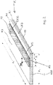
- Fig. 1 and 2 show schematically an adhesive tape K, which is on a as in Figures 3a to 3e shown flat web material RB, which is wound on a roll R, can be arranged.
- the adhesive tape K has a carrier layer K3.
- the carrier layer K3 has a first surface K31 and a second surface K32 opposite the first surface K31.
- a first adhesive layer K1 is arranged on the first surface K31.
- the first layer of adhesive K1 can be arranged directly or indirectly on the carrier layer K3.
- “directly” means that the first layer of adhesive K1 rests directly on the carrier layer K3.
- one or more additional layers such as functional layers, for example, for detecting the adhesive tape K by means of appropriate detectors provided by means of suitable layers, such as, for example, lacquer layers, metal layers (e.g.
- the first adhesive layer K1 is arranged directly on the carrier layer K3 or the first surface K31 of the carrier layer K3.
- the first layer of adhesive K1 is arranged over the entire area on the first surface K31 of the carrier layer K3. It is also possible, however, for the first adhesive layer K1 to be arranged only on certain sections of the first surface K31 of the carrier layer K3 and thus over part of the area, so that two or more first adhesive layers K1 can be present next to one another.
- a separating cover K5 is arranged on the first adhesive layer K1, which has a perforation or a slot K5S in the longitudinal direction I K of the adhesive tape K, so that the separating cover K5 can be cut through at least in regions.
- the separating cover K5 can, for example, be a siliconized separating paper or else a separating film.
- a second adhesive layer K2 is arranged on the second surface K32 of the carrier layer K3, which is arranged indirectly on the carrier layer K3, since a surface coating K4 is arranged between the second adhesive layer K2 and the carrier layer K3.
- the surface coating K4 and the second adhesive layer K2 are arranged on a surface area FB of the second surface K32 of the carrier layer K3 which is smaller than the total area of the second surface K32 of the carrier layer K3.
- the surface coating K4 can be used to create a predetermined breaking area for the planar splitting of the adhesive tape K, the predetermined breaking area corresponding to the area FB on which the surface coating K4 is arranged together with the second adhesive layer K2.
- the surface area FB and thus the predetermined breaking area is smaller than the adhesive layer K2.
- FB K2 - K6.
- the surface coating K4 is greater than or equal to the area of the second adhesive layer K2.
- papers, foils - for example made of plastics -, nonwovens, multilayer laminates - for example made of several papers or several film materials or paper (s) and film (s) - can be used as the carrier layer K3.
- Laminates At least one layer of a conventional carrier layer material - such as paper and / or plastic - with a metal foil layer (such as in particular aluminum) can also be used.
- a layer of a chemical substance for example a binder, can be applied as the surface coating K4 to the surface K32 of the carrier layer K3.
- the chemical substance can, for example, be applied in the form of a solution or a dispersion and then dried, so that a dry layer (for example continuous film or porous coating) is present that rests on the surface K32 of the carrier layer K3.
- a dry layer for example continuous film or porous coating
- the solution, suspension or dispersion to form the surface coating K4 penetrates into the surface K32 of the carrier layer K3. This can be of particular interest for the embodiments in which the predetermined breaking area lies within the surface coating K4 and splits it in the splitting process due to a cohesive break.
- a coated paper can be used as the carrier layer K3, or such a carrier layer K3 can be used which has a coated paper on its one surface.
- a coating slip (also known as coating color) is often evenly applied to papers - such as base papers -, for example by coating with a knife, roller, brush, nozzle (e.g. air nozzle coating), or for example by means of curtain coating.
- the surface coating obtained in this way is also referred to as "coating”, and the treated paper as “coated paper”. Papers can be coated on one or both sides.
- the coating colors that can be used are usually composed of several of the following main components: water, pigments (usually mineral white pigments or white minerals), dispersants for pigments (usually Polyacrylates), binders (usually synthetic acrylate or styrene-butadiene copolymers), starch, thickeners (usually methyl cellulose derivatives or acrylate copolymers), additives to regulate viscosity and water retention, calendering aids (e.g. waxes), Release agents (e.g. polyvinyl alcohol), auxiliaries to reduce wet abrasion, shading dyes (e.g. optical brighteners), anti-foaming agents, biocides.
- water usually composed of several of the following main components: water, pigments (usually mineral white pigments or white minerals), dispersants for pigments (usually Polyacrylates), binders (usually synthetic acrylate or styrene-butadiene copolymers), starch, thickeners (usually methyl cellulose derivatives or acrylate cop
- the solids content in a coating slip is usually around 65 to 70% by weight, of which almost 90% is pigments.
- the binder content is usually 10 to 15% by weight (based on the dry substance); the binder content can be used in particular to influence the properties relevant for the splitting process in the predetermined breaking point (such as the tendency towards adhesive or cohesive separation, etc.). All other additives are usually added in low concentrations (in particular below 1% by weight).
- the selection of the pigments of commercially available papers depends on the quality requirements of the coated papers, for example whiteness, opacity, smoothness, gloss, pick resistance, printability.
- a chemical composition can be used as the material for the coating slip, the main constituent of which is one or more minerals - such as chalk (calcium carbonate), talc, china clay (kaolin, for example china clay) -, one or more protein derivatives - such as casein or several polysaccharides - such as, for example, starch -, one or more plastic particles or a mixture of two or more representatives of the aforementioned substances.
- minerals - such as chalk (calcium carbonate), talc, china clay (kaolin, for example china clay) -, one or more protein derivatives - such as casein or several polysaccharides - such as, for example, starch -, one or more plastic particles or a mixture of two or more representatives of the aforementioned substances.
- special pigments such as satin white (calcium aluminate sulfate) or calcined clays can be used in addition or instead.
- the chemical composition for the coating slip in particular at least some, preferably as the main constituent, that is to say more than 50%, more preferably also exclusively, those components that are in the form of flakes and / or layers can be selected.
- suitable minerals Leaflet or layered substances, especially minerals, have such a structure that the interactions between the building blocks are not comparable in all dimensions, but are greater within a level (layer) than between the levels (definition according to Römpp). The different interaction shows up in different atomic distances and leads to a mostly leaf-like cleavage.
- Well-known examples of such compounds are graphite, montmorillonite and mica.
- the slidable layers which are either flat, as in graphite, or corrugated, as in phyllosilicates, can easily be moved parallel to one another.
- the choice of lamellar or layer-shaped components of the coating slip can be used for particularly good controllability of the cleavage in the sense of the inventive teaching.
- Coating slips based on kaolin, in particular in flake form, and / or based on titanium dioxide are particularly advantageously used, since particularly good compatibility with the adhesives has been shown for this.
- Such papers coated on one or both sides can be used particularly well. Since the interface between paper and line or the line itself represents the predetermined breaking surface of the system, it is advantageous to choose paper that is only coated on one side.
- coated papers can be used for the carrier material, the coating of which can be split off in the course of the splicing process on the surfaces of the carrier provided with a second adhesive.
- uncoated papers can only be provided with a line for use as a carrier material for the adhesive tape according to the invention, or a paper that has already been provided with a line is provided with a further surface coating, the splitting during the splicing process in particular between the original - first - Line and the further surface coating can take place.
- compositions such as those used as laminating compounds, for example in the documents, are also advantageously suitable as chemical substances for the surface coating EP 1 076 026 A and EP 2 116 581 A are described.
- such laminating compounds usually contain additives that are weakly separating and, if necessary, also elasticizing additives.
- the splitting properties in particular the tendency to cohesive or adhesive breakage
- An excellent composition contains, in addition to a binder, silicone-free and, if necessary, elasticizing additives with weak release properties.
- Modified starches for example, or binders such as have long been in use for wet adhesive tapes can be used as binders.
- talc stearyl derivatives such as calcium stearate or dispersions of - in particular silicone and fluorine-free - polymeric release agents, such as dispersions based on copolymers of stearyl methacrylate or stearyl derivatives of maleic acid with styrene, can be used as release agents.
- Water-soluble polyglycols for example, can serve as elasticizing agents which can optionally be added.
- aqueous preparations with 10 to 90% by weight of binder and 10 to 90% by weight of release agent and up to 60% by weight of elasticizing agent can be used as the mass for producing the surface coating.
- the preferred binders are starch derivatives, for example anionic potato starch, in proportions of 30 to 70% by weight.
- the release agents used are preferably talc, calcium stearate and / or release copolymers with stearyl groups in proportions of 30 to 80% by weight.
- Polypropylene or polyethylene glycols, in particular water-soluble ones, preferably in amounts between 0 to 15% by weight have proven to be very suitable for elasticization.
- the higher molecular weight products that are solid at room temperature are primarily used.
- Other elasticizing agents that can be used well in larger proportions are gum arabic and plastics with a similar property profile. Fillers and / or thickeners can be added to the mass, in particular in a proportion of up to 30% by weight.
- compositions that can be used excellently for producing the surface coating comprises at least one polysaccharide component and one surfactant component.
- the composition used for the surface coating is such a mass which, in addition to a binder, in particular a polysaccharide component, comprises at least one surfactant component which in particular serves as a release agent.
- the Surfactant component can be a single surfactant, but a surfactant component composed of two or more surfactants can also be used. If necessary, the composition can advantageously comprise further components, such as, in particular, elasticizing additives (hereinafter also elasticizing agents).
- the polysaccharide component is starch, gum arabic or derivatives of the aforementioned compounds.
- the binder component can also be, for example, a stearate, in particular magnesium and calcium stearate.
- the binder component can also be composed in such a way that a mixture of starch with one or more other binders is used.
- Compositions particularly preferred according to the invention have a polysaccharide content of up to 98% by weight, particularly preferably up to 85 to 95% by weight, even better from 90 to 95% by weight.
- Starch derivatives can be used with particular preference, in particular hydroxypropyl ether based on potato starch.
- Such a starch is available, for example, from the Emsland starch company under the name Emsol K55.
- the surfactant content is very preferably 2 to 20, better 5 to 15, best 5 to 10% by weight.
- the above proportions refer to the mixture of surfactant and polysaccharide both for the polysaccharide component and for the surfactant component, in each case in the form of the amount based on the solids content.
- Solvent in particular water, is also present, preferably in proportions of 50 to 80%. In particular, one can proceed in this way by adding the solid surfactant to a 20 to 40% strength aqueous solution of the polysaccharide component.
- Talc calcium stearate and / or separating copolymers with stearyl groups in proportions of 30 to 80% by weight can also be used here as further additives.
- Polypropylene or polyethylene glycols preferably in amounts between 0 to 15% by weight, have proven to be very suitable for elasticization. The higher molecular weight products that are solid at room temperature are primarily used.
- Other elasticizing agents that can be used well in larger proportions are gum arabic and plastics with a similar property profile.
- the first layer of adhesive K1 and / or the second layer of adhesive K2 can be designed as self-adhesives.
- the PSAs are able to wet a substrate to be bonded sufficiently at the application temperature without activation by solvents or by heat - but usually by the influence of a more or less high pressure - so that there is a bond between the adhesive and the substrate be able to develop sufficient interactions.
- the main influencing parameters here are pressure and contact time.
- the special properties of the PSAs are due, inter alia, in particular to their viscoelastic properties.
- the adhesive used for the first adhesive layer K1 is preferably selected to have a high tack (initial tack), while a shear-resistant (self) adhesive is advantageously used for the second adhesive layer K2.
- Systems based on acrylate can be used as self-adhesives, for example as pure acrylate adhesives (homopolymers and copolymers, each exclusively based on acrylate and / or methacrylate monomers; so-called 100% systems), as adhesives based on copolymers from acrylic monomers - acrylates , Methacrylates and non-acrylic monomers, or as adhesives based on blends, containing at least two representatives from the list comprising pure polyacrylates, copolymers of acrylic monomers and non-acrylic monomers and (co) polymers only of non-acrylic monomers. Both water-soluble and water-insoluble acrylates can advantageously be used. Acrylates polymerized in water (waterborne systems) can also be used with particular advantage.
- PSAs for example, for example, mixtures of rubber-based adhesives
- Adhesives natural rubber and / or synthetic rubber
- acrylate adhesives or mixtures of natural rubber with synthetic rubber can also be used.
- Mixtures of various components selected from the group of silicone adhesives, rubber systems (natural rubber and / or synthetic rubber) and / or acrylate systems can also be used.
- the second layer of adhesive K2 is applied in the form of a strip, the second layer of adhesive K2 extending parallel to an edge region LK3 of the carrier layer K3 extending in the longitudinal direction I K of the adhesive tape K.
- the second adhesive layer K2 is arranged at a distance A from the edge region LK3 of the carrier layer K3 extending in the longitudinal direction I K of the adhesive tape K.
- the distance A formed as an indentation can be up to 10 mm, preferably between 0.5 to 5 mm, very preferably between 1 to 3 mm. In particular, the distance A can be 2 mm.
- the splitting work which has to be expended in order to completely split the predetermined breaking area can be set independently of the width of the main carrier K3. This is an advantage over the systems in which the predetermined breaking surface extends over the entire area over the width b K of the adhesive tape K.
- splitting force an increased maximum force is required to split the splitting system (splitting force). Furthermore, you need a force at a lower level to split over the entire width of the split strip (further splitting force).
- the splitting force must be set so high that the product does not open prematurely due to the centrifugal and aerodynamic forces acting during acceleration; on the other hand, the further splitting force must be set so low ensure that the complete splitting of the gap system does not lead to web breaks.
- An essential quality factor is the constant further splitting force of the splitting strip, which is set at a defined level within narrow limits.
- a deactivated adhesive area K6 is formed on a surface K21 of the second adhesive layer K2 pointing in the direction of the carrier layer K3.
- the deactivated adhesive area K6 allows a crack to be introduced into the predetermined breaking area in a targeted manner.
- the deactivated adhesive area K6 has no adhesive effect, so that in the deactivated adhesive area K6 no cohesive connection is formed between the second adhesive layer K2 and the surface coating K4 and / or the carrier layer K3.
- the deactivated adhesive area K6 is arranged adjacent to the edge area LK2 of the second adhesive layer K2 which extends in the longitudinal direction I K of the adhesive tape K, so that the deactivated adhesive area K6 is flush with the edge area LK2 of the second adhesive layer K2.
- the deactivated adhesive area K6 extends over the entire length of the second adhesive layer K2.
- the deactivated adhesive area K6 has the shape of a strip. However, it is also possible for the deactivated adhesive area K6 to extend only over a partial area of the length of the second adhesive layer K2. Furthermore, it is also possible for the deactivated adhesive area K6 to have a wave shape.
- the deactivated adhesive region K6 has a width b dK which is smaller than half the total width bs of the second adhesive layer K2.
- the deactivated adhesive area K6 can have a width of 0.5 mm b dK 5 mm, preferably 1 mm b dK 3 mm.
- the deactivated adhesive area particularly preferably has a width of 1.5 mm b dK 2.5 mm.
- the deactivated adhesive region K6 on the surface K21 of the second adhesive layer K2 can be formed in various ways.
- the deactivated adhesive region K6 can be formed by applying a paint or a lacquer to the surface K21 of the second adhesive layer K2 pointing in the direction of the carrier layer K3. Furthermore, the deactivated adhesive region K6 can be formed by applying a web-shaped, non-adhesive strip of material to the surface K21 of the second adhesive layer K2 pointing in the direction of the carrier layer K3. Furthermore, the deactivated adhesive region K6 can be formed by applying a powder material to the surface K21 of the second adhesive layer K2 pointing in the direction of the carrier layer K3.
- the deactivated adhesive area K6 is formed by overcrosslinking by means of irradiation of the surface K21 of the second adhesive layer K2 pointing in the direction of the carrier layer K3.
- the surface K21 of the second adhesive layer K2 is preferably irradiated by means of an ultraviolet light in order to trigger the crosslinking process of the surface K21 of the second adhesive layer K2.
- an adhesive layer K2 is used which can be crosslinked by means of UV radiation.
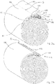
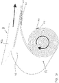
- an on-the-fly roll change is shown by way of example, the preparation and implementation of a on-the-fly roll change of the flat web material RB by means of the adhesive tape K according to the invention being shown.
- On-the-fly roll changes can in particular be carried out in such a way that the new roll R of a flat web material RB is first prepared by fixing the flat web section R1 of the new roll R, which forms the top winding, to the flat web section R2, which forms the second winding, of the new roll R with an adhesive tape K according to the invention becomes.
- the adhesive tape K is applied to the flat web section R2. Then the first adhesive layer K1 of the adhesive tape K is only partially exposed. This can be done by removing the separating cover K5 on it, as shown in Fig. 1 can be seen has a slot or a perforation K5S in the longitudinal direction I K of the adhesive tape K, so that the separating cover K5 is divided into two parts K51, K52 or has a predetermined breaking point for producing two parts K51, K52, and then only one part separating cover K51 is pulled off so that, as in Fig. 3a can be seen a adhesive area K11 and a non-adhesive area K12 - because it is covered - and area of the first adhesive layer K1, each running in the longitudinal direction I K of the adhesive tape K, remain.
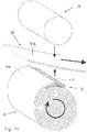
- This adhesive tape K is now used to glue the flat web section R1 of a new roll R, which forms the top winding - the topmost flat web layer - to the flat web section R2, which forms the second top winding - the second flat web layer - of the new roll R.
- the adhesive layer K2 is glued to the flat web section R2.
- the partial area of the separating cover K51 is uncovered and the flat web section R1 is glued to the free partial area of the adhesive area K11. This will connect R1 to R2.
- the protruding flag R3 of the flat web section R1 bonded to the first adhesive layer K1 is then cut to length in the area of the dashed line S to the area K12 of the first adhesive layer K1 covered by the remaining part of the separating cover K52 - cut off, torn off or the like - so that then The resulting end E of the flat web material RB essentially adjoins the remaining release cover K52 of the first adhesive layer K1 of the adhesive tape K.
- the part K52 of the separating cover K5 that is still present can then be peeled off, so that an exposed adhesive mass surface K12 is present, which can be used for bonding to the old flat web B that is running off, as in FIG Figures 3b-3e is shown. It is advantageous if the adhesive surface K12, viewed in the running direction of the flat web material RB, is at least as wide as the adhesive region K11.
- the so prepared roll R is then placed next to an almost completely unwound old roll B to be replaced and accelerated to essentially the same peripheral speed as this. It is then pressed against the flat web material RB of the old roll B, for example with the aid of a pressure cylinder A, the exposed surface area K12 of the first adhesive layer K1 of the adhesive tape K with the flat web material RB of the old roll B at essentially the same speeds of the rolls R, B is glued.
- Different materials can also be spliced together.
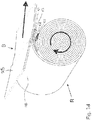
- the adhesive tape K opens in the predetermined breaking area FB, as in FIG Fig. 3d can be seen, so that the flat web material RB of the new roll R can be threaded into the process with the flat web material RB of the old roll B to which it is glued, as in FIG Figure 3e can be seen. In this way, a continuous process sequence can be ensured with a flying roll change.
- the split-off remainder of the surface coating K4 completely covers the second adhesive layer K2 after splitting, so that no adhesions occur in the further machine cycle.
Description
Die Erfindung betrifft ein Klebeband für den fliegenden Rollenwechsel von auf Rollen aufgewickeltem Flachbahnmaterial mit einer Trägerschicht, welche eine erste Oberfläche und eine der ersten Oberflächen gegenüberliegende zweite Oberfläche aufweist, einer ersten Klebmassenschicht, welche auf der ersten Oberfläche der Trägerschicht mittelbar oder unmittelbar zumindest teilflächig angeordnet ist, einer zweiten Klebmassenschicht, welche auf zumindest einem Flächenbereich der zweiten Oberfläche der Trägerschicht angeordnet ist, und mindestens einer Sollbruchfläche zum flächigen Spalten des Klebebands, wobei die Sollbruchfläche derart ausgebildet ist, dass der zumindest eine Flächenbereich eine Oberflächenbeschichtung aufweist, welche zwischen der Trägerschicht und der zweiten Klebmassenschicht angeordnet ist, wobei die Adhäsionskräfte der zweiten Klebmassenschicht zur Oberflächenbeschichtung größer sind als die Adhäsionskräfte der Oberflächenbeschichtung zur Trägerschicht, und/oder wobei die Adhäsionskräfte der zweiten Klebmassenschicht zur Oberflächenbeschichtung größer sind als die Kohäsionskräfte innerhalb der Oberflächenbeschichtung. Weiter betrifft die Erfindung ein Flachbahnmaterial, welches auf einer Rolle aufgewickelt ist und ein derartiges Klebeband aufweist. Ferner betrifft die Erfindung eine Verwendung eines derartigen Klebebands.The invention relates to an adhesive tape for the flying roll change of flat web material wound on rolls with a carrier layer which has a first surface and a second surface opposite the first surfaces, a first adhesive layer which is arranged directly or indirectly at least partially on the first surface of the carrier layer , a second layer of adhesive, which is arranged on at least one surface area of the second surface of the carrier layer, and at least one predetermined breaking area for the planar splitting of the adhesive tape, wherein the predetermined breaking area is designed such that the at least one surface area has a surface coating that is between the carrier layer and the second layer of adhesive is arranged, the adhesion forces of the second layer of adhesive to the surface coating being greater than the forces of adhesion of the surface coating to the carrier layer, and / or where d The adhesive forces of the second layer of adhesive for surface coating are greater than the cohesive forces within the surface coating. The invention also relates to a flat web material which is wound on a roll and has such an adhesive tape. The invention also relates to a use of such an adhesive tape.
Ein entsprechendes Klebeband ist aus der
Es ist die Aufgabe der vorliegenden Erfindung, ein Klebeband sowie ein Flachbahnmaterial mit einem derartigen Klebeband zur Verfügung zu stellen, bei welchen das Spalten des Klebebands im Bereich der Sollbruchfläche weiter verbessert werden kann.It is the object of the present invention to provide an adhesive tape and a flat web material with such an adhesive tape in which the splitting of the adhesive tape in the area of the predetermined breaking surface can be further improved.
Diese Aufgabe wird mit den Merkmalen der unabhängigen Ansprüche gelöst. Vorteilhafte Ausgestaltungen und Weiterbildungen der Erfindung sind in den abhängigen Ansprüchen angegeben.This object is achieved with the features of the independent claims. Advantageous refinements and developments of the invention are given in the dependent claims.
Das Klebeband gemäß der Erfindung zeichnet sich dadurch aus, dass die zweite Klebmassenschicht an einer in Richtung Trägerschicht zeigenden Oberfläche einen deaktivierten Klebebereich aufweist.The adhesive tape according to the invention is characterized in that the second adhesive layer has a deactivated adhesive area on a surface pointing in the direction of the carrier layer.
In dem deaktivierten Klebebereich weist die zweite Klebmassenschicht, insbesondere die in Richtung der Trägerschicht zeigende Oberfläche der zweiten Klebmassenschicht, keine Klebwirkung auf. Dadurch ist in dem deaktivierten Klebebereich die stoffschlüssige Verbindung der zweiten Klebmassenschicht mit der Oberflächenbeschichtung und/oder der Trägerschicht aufgehoben. Durch den deaktivierten Klebebereich wird eine Art Überstand der zweiten Klebmassenschicht im Bereich der Sollbruchfläche erreicht. Durch diesen Überstand kann das Spaltverhalten im Bereich der Sollbruchfläche verbessert werden, da der Beginn bzw. Start des Spaltens im Bereich der Sollbruchfläche durch den Überstand noch definierter und kontrollierter erfolgen kann. Der durch den deaktivierten Klebebereich ausgebildete Überstand stellt eine Art Aktivierungsbereich für das Spalten des Klebebands im Bereich der Sollbruchfläche dar, so dass ein Riss gezielt und definiert in die Spaltebene der Sollbruchfläche eingeleitet werden kann. Diese Anspalthilfe begünstigt ein noch sicheres und sanfteres Anspalten im Bereich der Sollbruchfläche, wodurch insbesondere auch die Wahrscheinlichkeit eines fehlerhaften Anspaltens reduziert werden kann. Die Ausbildung des deaktivierten Klebebereichs kann dadurch realisiert werden, dass vor dem Aufbringen, insbesondere Auflaminieren, der zweiten Klebmassenschicht auf die Oberflächenbeschichtung und damit auf die Trägerschicht die Klebwirkung der in Richtung der Trägerschicht zeigenden Oberfläche der zweiten Klebmassenschicht bereichsweise deaktiviert bzw. aufgehoben wird. Die Oberflächenbeschichtung kann die gesamte oder auch nur eine Teilfläche der zweiten Klebmassenschicht ausmachen.In the deactivated adhesive area, the second adhesive layer, in particular the surface of the second adhesive layer pointing in the direction of the carrier layer, has no adhesive effect. As a result, the material connection of the second adhesive layer with the surface coating and / or the carrier layer is canceled in the deactivated adhesive area. The deactivated adhesive area achieves a kind of protrusion of the second adhesive layer in the area of the predetermined breaking area. This protrusion can improve the splitting behavior in the area of the predetermined breaking area, since the beginning or start of the splitting in the area of the predetermined breaking area can be made even more defined and controlled by the protrusion. The protrusion formed by the deactivated adhesive area represents a type of activation area for splitting the adhesive tape in the area of the predetermined breaking area, so that a tear can be introduced in a targeted and defined manner into the gap plane of the predetermined breaking area. This splitting aid promotes an even more reliable and gentle splitting in the area of the predetermined breaking surface, whereby the probability of an incorrect splitting can be reduced in particular. The formation of the deactivated adhesive area can be realized in that before the application, in particular lamination, of the second adhesive layer onto the surface coating and thus onto the carrier layer, the adhesive effect of the surface of the second adhesive layer facing in the direction of the carrier layer is deactivated or canceled in certain areas. The surface coating can make up the entire or also only a partial area of the second adhesive layer.
Um ein besonders gutes Anspaltverhalten erreichen zu können, ist der deaktivierte Klebebereich bevorzugt angrenzend zu einem sich in Längsrichtung des Klebebands erstreckenden Kantenbereich der zweiten Klebmassenschicht angeordnet.In order to be able to achieve particularly good splitting behavior, the deactivated adhesive area is preferably arranged adjacent to an edge area of the second adhesive layer extending in the longitudinal direction of the adhesive tape.
Die zweite Klebmassenschicht ist bevorzugt beabstandet zu einem sich in Längsrichtung des Klebebands erstreckenden Kantenbereich der Trägerschicht angeordnet. Dieser Abstand bildet eine Art Einrückung der zweiten Klebmassenschicht relativ zu der dem Kantenbereich der Trägerschicht aus. Die zweite Klebmassenschicht schließt damit vorzugsweise nicht bündig mit dem Kantenbereich der Trägerschicht ab, sondern ist mit einem Abstand zu dem Kantenbereich der Trägerschicht angeordnet. Der Abstand A kann vorzugsweise 0,5 mm ≤ A ≤ 5 mm, bevorzugt 1 mm ≤ A ≤ 3 mm sein. Durch den Abstand der zweiten Klebmassenschicht zu dem sich in Längsrichtung des Klebebands erstreckenden Kantenbereich der Trägerschicht kann das Spaltverhalten, insbesondere das Anspalten, der Sollbruchfläche weiter verbessert werden. Durch den Abstand bzw. die Einrückung kann eine erforderliche Kraftspitze beim Anspalten reduziert werden. Zur Überwindung der Spaltfestigkeit an der vorderen Kante wird dabei eine erhöhte, maximale Kraft zum Anspalten des Systems benötigt (Anspaltkraft, Initialspaltkraft zum Einleiten des Spaltvorgangs der Sollbruchstelle). Des Weiteren benötigt man eine Kraft auf niedrigerem Niveau zum Spalten über die gesamte Breite des Splicebandes (Weiterspaltkraft). Das Produkt aus der aufgewendeten Kraft und der Breite des Spaltsystems ist die Arbeit, die zum Spalten benötigt wird (Spaltarbeit). Die Anspaltkraft sollte so hoch eingestellt sein, dass das Produkt durch die bei der Beschleunigung wirkenden Fliehkräfte und aerodynamischen Kräfte nicht vorzeitig öffnet, zum anderen muss die Spaltarbeit so gering eingestellt sein, dass die benötigte Arbeit für das komplette Durchspalten des Sollbruchfläche nicht zu Abrissen führt. Durch die Ausgestaltung der erfindungsgemäßen Klebebänder lassen sich für diese Parameter hervorragende Werte realisieren.The second adhesive layer is preferably arranged at a distance from an edge region of the carrier layer extending in the longitudinal direction of the adhesive tape. This distance forms a type of indentation of the second adhesive layer relative to that of the edge region of the carrier layer. The second layer of adhesive therefore preferably does not end flush with the edge region of the carrier layer, but is with it arranged at a distance from the edge region of the carrier layer. The distance A can preferably be 0.5 mm A 5 mm, preferably 1 mm A 3 mm. The gap between the second adhesive layer and the edge region of the carrier layer extending in the longitudinal direction of the adhesive tape can further improve the splitting behavior, in particular the splitting, of the predetermined breaking surface. A necessary force peak when splitting can be reduced by the distance or the indentation. In order to overcome the splitting strength at the front edge, an increased maximum force is required to split the system (splitting force, initial splitting force to initiate the splitting process of the predetermined breaking point). Furthermore, you need a force at a lower level to split over the entire width of the splice tape (further splitting force). The product of the applied force and the width of the splitting system is the work that is required for splitting (splitting work). The splitting force should be set so high that the product does not open prematurely due to the centrifugal and aerodynamic forces acting during acceleration; on the other hand, the splitting work must be set so low that the work required for the complete splitting of the predetermined breaking surface does not lead to tears. The design of the adhesive tapes according to the invention enables excellent values to be achieved for these parameters.
Um ein gleichmäßiges Spaltverhalten der Sollbruchfläche über die gesamte Länge der Sollbruchfläche erreichen zu können, erstreckt sich der deaktivierte Klebebereich vorzugsweise über die gesamte Länge der zweiten Klebmassenschicht. Alternativ ist es aber auch möglich, dass sich der deaktivierte Klebebereich abschnittsweise und damit nur teilflächig über die Länge der zweiten Klebmassenschicht erstreckt. Die Länge der Sollbruchfläche und die Länge der Klebmassenschicht erstrecken sich in Längsrichtung des Klebebandes.In order to be able to achieve a uniform splitting behavior of the predetermined breaking surface over the entire length of the predetermined breaking surface, the deactivated adhesive area preferably extends over the entire length of the second layer of adhesive. Alternatively, however, it is also possible that the deactivated adhesive area extends in sections and thus only over part of the area over the length of the second adhesive layer. The length of the predetermined breaking surface and the length of the adhesive layer extend in the longitudinal direction of the adhesive tape.
Der deaktivierte Klebebereich erstreckt sich vorzugsweise über einen Teilbereich der Gesamtbreite der zweiten Klebmassenschicht. Bevorzugt weist der deaktivierte Klebebereich dabei eine Breite bdK auf, welche kleiner ist als die Hälfte der Gesamtbreite bs der zweiten Klebmassenschicht. Hierdurch kann trotz eines verbesserten Spaltverhaltens der Sollbruchfläche noch eine ausreichend gute Klebewirkung der zweiten Klebmassenschicht hin zu der Oberflächenbeschichtung und/oder der Trägerschicht gewährleistet werden, um vor dem Spaltvorgang an der Sollbruchfläche ein Abwickeln des Flachbahnmaterials sicher verhindern zu können.The deactivated adhesive area preferably extends over a partial area of the total width of the second adhesive layer. The deactivated adhesive area preferably has a width b dK which is smaller than half the total width bs of the second layer of adhesive. In this way, despite an improved splitting behavior of the predetermined breaking area, a sufficiently good adhesive effect of the second adhesive layer towards the surface coating and / or the carrier layer can be ensured in order to be able to reliably prevent the flat web material from unwinding at the predetermined breaking area before the splitting process.
Der deaktivierte Klebebereich kann eine Breite von 0,5 mm ≤ bdK ≤ 5 mm, bevorzugt von 1 mm ≤ bdK ≤ 3 mm aufweisen. Besonders bevorzugt weist der deaktivierte Klebebereich eine Breite von 1,5 mm ≤ bdK ≤ 2,5 mm auf.The deactivated adhesive area can have a width of 0.5 mm b dK 5 mm, preferably 1 mm b dK 3 mm. The deactivated adhesive area particularly preferably has a width of 1.5 mm b dK 2.5 mm.
Der deaktivierte Klebebereich an der Oberfläche der zweiten Klebmassenschicht, die in Richtung der Sollbruchfläche zeigt, kann durch verschiedene Art und Weisen ausgebildet werden.The deactivated adhesive area on the surface of the second adhesive layer, which points in the direction of the predetermined breaking area, can be formed in various ways.
Beispielsweise kann der deaktivierte Klebebereich durch Aufbringen einer Farbe oder eines Lacks auf die in Richtung Trägerschicht zeigende Oberfläche der zweiten Klebmassenschicht ausgebildet sein. Diese Farben oder Lacke können beispielsweise sogenannte UV-Lacke oder UV-Farben sein. Es sind aber auch andere vernetzende oder trocknende, beispielsweise lufttrocknende, Farben oder Lacke einsetzbar. Durch das Aushärten der Farbe oder des Lacks entsteht eine permanente Sperrschicht, wodurch eine Deaktivierung des Klebebereichs erreicht werden kann. Das Aufbringen der Farbe oder des Lacks kann beispielsweise durch ein Bedruckungsverfahren, zum Beispiel mittels eines Druckwerks oder Inkjets, erfolgen. Ferner kann die Farbe oder der Lack auch aufgestrichen werden, zum Beispiel mittels in einer Halterung angeordneten Stiften. Hierbei kann eine besonders geringe Dicke im µm-Bereich erreicht werden. Zudem ist eine Deaktivierung in einem Teilbereich möglich. Jegliche andere Auftragsverfahren können ebenfalls eingesetzt werden.For example, the deactivated adhesive area can be formed by applying a paint or a lacquer to the surface of the second adhesive layer pointing in the direction of the carrier layer. These inks or varnishes can be, for example, so-called UV varnishes or UV inks. However, other crosslinking or drying, for example air-drying, paints or lacquers can also be used. The curing of the paint or varnish creates a permanent barrier layer, which can deactivate the adhesive area. The paint or the lacquer can be applied, for example, by a printing process, for example by means of a printing unit or inkjet. Furthermore, the paint or varnish can also be painted on, for example by means of pens arranged in a holder. A particularly small thickness in the µm range can be achieved here. Deactivation is also possible in a sub-area. Any other application method can also be used.
Weiter kann der deaktivierte Klebebereich durch Aufbringen eines bahnförmigen, nicht klebenden Materialstreifens auf die in Richtung Trägerschicht zeigende Oberfläche der zweiten Klebmassenschicht ausgebildet sein. Der Materialstreifen kann beispielsweise aus einem Kunststoffmaterial oder aber auch aus einem Metallmaterial ausgebildet sein. Beispielsweise kann der Materialstreifen ein Folienstreifen, wie beispielsweise eine Aluminiumfolie oder eine PET-Folie sein. Der Materialstreifen sollte eine möglichst geringe Dicke aufweisen. Beispielsweise kann der Materialstreifen eine Dicke von ca. 2 µm aufweisen. Aufgebracht werden kann der Materialstreifen beispielsweise durch Auflaminieren, wodurch eine vollständige Abdeckung und damit eine besonders gute Deaktivierung der zweiten Klebmassenschicht erreichbar ist.Furthermore, the deactivated adhesive area can be formed by applying a web-like, non-adhesive strip of material to the surface of the second adhesive layer pointing in the direction of the carrier layer. The material strip can for example be formed from a plastic material or else from a metal material. For example, the material strip can be a film strip, such as an aluminum film or a PET film. The material strip should be as thin as possible. For example, the material strip can have a thickness of approximately 2 μm. The material strip can be applied, for example, by lamination, as a result of which complete coverage and thus particularly good deactivation of the second adhesive layer can be achieved.
Ferner kann der deaktivierte Klebebereich durch Aufbringen eines Pudermaterials auf die in Richtung Trägerschicht zeigende Oberfläche der zweiten Klebmassenschicht ausgebildet sein. Als Pudermaterial kann beispielsweise Talkum, Kreide, Calciumcarbonat, Kaolin, usw. verwendet werden. Das Aufbringen des Pudermaterials kann beispielsweise durch ein Bepudern erfolgen, wodurch eine besonders dünne Aufbringung erreicht werden kann und auch eine Deaktivierung in Teilbereichen möglich ist.Furthermore, the deactivated adhesive area can be formed by applying a powder material to the surface of the second adhesive layer pointing in the direction of the carrier layer. For example, talc, chalk, calcium carbonate, kaolin, etc. can be used as powder material. The powder material can be applied, for example, by powdering, whereby a particularly thin application can be achieved and deactivation is also possible in partial areas.
Auch ist es möglich, dass die zweite Klebmassenschicht durch Übervernetzung mittels einer Bestrahlung der in Richtung Trägerschicht zeigenden Oberfläche zu deaktivieren. Die Bestrahlung der Oberfläche der zweiten Klebmassenschicht erfolgt vorzugsweise mittels eines ultravioletten Lichts, um den Vernetzungsvorgang der Oberfläche der zweiten Klebmassenschicht auszulösen. Durch die Vernetzung der Oberfläche der zweiten Klebmassenschicht kann in den Bereichen der Bestrahlung die Klebwirkung der zweiten Klebmassenschicht aufgehoben werden, so dass der deaktivierte Klebebereich ausgebildet werden kann. Bei dieser Art der Ausbildung des deaktivierten Klebebereichs ist es daher nicht notwendig, ein zusätzliches Material auf die zweite Klebmassenschicht aufzubringen, um die Klebwirkung aufzuheben.It is also possible for the second layer of adhesive to be deactivated by overcrosslinking by means of irradiation of the surface facing in the direction of the carrier layer. The surface of the second adhesive layer is preferably irradiated by means of an ultraviolet light in order to trigger the crosslinking process of the surface of the second adhesive layer. As a result of the crosslinking of the surface of the second adhesive layer, the adhesive effect of the second adhesive layer can be canceled in the areas of irradiation, so that the deactivated adhesive area can be formed. With this type of formation of the deactivated adhesive area, it is therefore not necessary to apply an additional material to the second layer of adhesive in order to cancel the adhesive effect.
Die Lösung der erfindungsgemäßen Aufgabe erfolgt ferner mittels eines Flachbahnmaterials, welches auf eine Rolle aufgewickelt ist, wobei das Flachbahnmaterial ein wie vorstehend beschrieben, aus- und weitergebildetes Klebeband aufweist.The object according to the invention is also achieved by means of a flat web material which is wound onto a roll, the flat web material having an adhesive tape designed and developed as described above.
Weiter ist erfindungsgemäß die Verwendung eines wie vorstehend beschriebenen, aus- und weitergebildeten Klebebands für einen fliegenden Rollenwechsel vorgesehen.The invention also provides for the use of an adhesive tape designed and developed as described above for a flying roll change.
Weitere, die Erfindung verbessernde Maßnahmen werden nachstehend gemeinsam mit der Beschreibung einer bevorzugten Ausgestaltung der Erfindung anhand der Figuren näher dargestellt. Es zeigen:
- Fig. 1
- eine schematische Darstellung eines Klebebands gemäß der Erfindung,
- Fig. 2
- eine weitere schematische Darstellung des Klebebands gemäß der Erfindung, und
- Fig. 3a bis 3e
- eine schematische Darstellung eines Flachbahnmaterials gemäß der Erfindung während eines fliegendes Rollenwechsels.
- Fig. 1
- a schematic representation of an adhesive tape according to the invention,
- Fig. 2
- a further schematic representation of the adhesive tape according to the invention, and
- Figures 3a to 3e
- a schematic representation of a flat web material according to the invention during a flying roll change.
Das Klebeband K weist eine Trägerschicht K3 auf. Die Trägerschicht K3 weist eine erste Oberfläche K31 und eine der ersten Oberfläche K31 gegenüberliegende zweite Oberfläche K32 auf.The adhesive tape K has a carrier layer K3. The carrier layer K3 has a first surface K31 and a second surface K32 opposite the first surface K31.
Auf der ersten Oberfläche K31 ist eine erste Klebmassenschicht K1 angeordnet. Die erste Klebmassenschicht K1 kann mittelbar oder unmittelbar auf der Trägerschicht K3 angeordnet sein. Unmittelbar bedeutet in diesem Zusammenhang, dass die erste Klebmassenschicht K1 direkt auf der Trägerschicht K3 aufliegt. Mittelbar bedeutet, dass zwischen der Trägerschicht K3 und der ersten Klebmassenschicht K1 eine oder mehrere weitere Schichten, wie beispielsweise Funktionsschichten - etwa für eine Detektierung des Klebebandes K durch entsprechende vorgesehene Detektoren mittels geeigneter Schichten, wie zum Beispiel Lackschichten, Metallschichten (z.B. Aluminiumschichten, etc.) oder anderer funktionelle Additive (wie Farbstoffe, Metallpulver, Getter usw.) enthaltende Schichten -, weitere Klebmassenschichten, Folienschichten, Schichten aus textilen Materialien, Schichten zur Haftverbesserung zwischen der ersten Oberfläche K31 der Trägerschicht K3 und der ersten Klebmassenschicht K1 und dergleichen vorgesehen sein können. Bei der hier gezeigten Ausgestaltung ist die erste Klebmassenschicht K1 unmittelbar auf der Trägerschicht K3 bzw. der ersten Oberfläche K31 der Trägerschicht K3 angeordnet. Dabei ist die erste Klebmassenschicht K1 vollflächig auf der ersten Oberfläche K31 der Trägerschicht K3 angeordnet. Es ist aber auch möglich, dass die erste Klebmassenschicht K1 nur auf bestimmten Abschnitten der ersten Oberfläche K31 der Trägerschicht K3 und damit teilflächig auf dieser angeordnet ist, so dass zwei oder mehr erste Klebmassenschichten K1 nebeneinander vorliegen können.A first adhesive layer K1 is arranged on the first surface K31. The first layer of adhesive K1 can be arranged directly or indirectly on the carrier layer K3. In this context, “directly” means that the first layer of adhesive K1 rests directly on the carrier layer K3. Indirectly means that between the carrier layer K3 and the first adhesive layer K1 one or more additional layers, such as functional layers, for example, for detecting the adhesive tape K by means of appropriate detectors provided by means of suitable layers, such as, for example, lacquer layers, metal layers (e.g. aluminum layers, etc.) ) or layers containing other functional additives (such as dyes, metal powder, getter, etc.), further layers of adhesive, film layers, layers of textile materials, layers to improve adhesion between the first surface K31 of the carrier layer K3 and the first layer of adhesive K1 and the like can be provided . In the embodiment shown here, the first adhesive layer K1 is arranged directly on the carrier layer K3 or the first surface K31 of the carrier layer K3. The first layer of adhesive K1 is arranged over the entire area on the first surface K31 of the carrier layer K3. It is also possible, however, for the first adhesive layer K1 to be arranged only on certain sections of the first surface K31 of the carrier layer K3 and thus over part of the area, so that two or more first adhesive layers K1 can be present next to one another.
Bei der hier gezeigten Ausgestaltung ist auf der ersten Klebmassenschicht K1 eine Trennabdeckung K5 angeordnet, die eine Perforation oder einen Schlitz K5S in Längsrichtung IK des Klebebands K aufweist, so dass die Trennabdeckung K5 zumindest bereichsweise durchgeschnitten sein kann. Die Trennabdeckung K5 kann beispielsweise ein silikonisiertes Trennpapier oder aber auch eine Trennfolie sein.In the embodiment shown here, a separating cover K5 is arranged on the first adhesive layer K1, which has a perforation or a slot K5S in the longitudinal direction I K of the adhesive tape K, so that the separating cover K5 can be cut through at least in regions. The separating cover K5 can, for example, be a siliconized separating paper or else a separating film.
Auf der zweiten Oberfläche K32 der Trägerschicht K3 ist eine zweite Klebmassenschicht K2 angeordnet, welche mittelbar auf der Trägerschicht K3 angeordnet ist, da zwischen der zweiten Klebmassenschicht K2 und der Trägerschicht K3 eine Oberflächenbeschichtung K4 angeordnet ist. Die Oberflächenbeschichtung K4 und die zweite Klebmassenschicht K2 sind auf einem Flächenbereich FB der zweiten Oberfläche K32 der Trägerschicht K3 angeordnet, welcher kleiner ist als die Gesamtfläche der zweiten Oberfläche K32 der Trägerschicht K3. Es ist aber auch möglich, dass die Oberflächenbeschichtung K4 die gesamte Oberfläche der Trägerschicht K3 abdeckt. Mittels der Oberflächenbeschichtung K4 kann eine Sollbruchfläche zum flächigen Spalten des Klebebands K geschaffen werden, wobei die Sollbruchfläche dem Flächenbereich FB entspricht, auf welchem die Oberflächenbeschichtung K4 zusammen mit der zweiten Klebmassenschicht K2 angeordnet ist. Dabei ist der Flächenbereich FB und damit die Sollbruchfläche kleiner als die Klebmassenschicht K2. Vorzugsweise ist FB = K2 - K6. Die Oberflächenbeschichtung K4 ist größer oder gleich der Fläche der zweiten Klebmassenschicht K2.A second adhesive layer K2 is arranged on the second surface K32 of the carrier layer K3, which is arranged indirectly on the carrier layer K3, since a surface coating K4 is arranged between the second adhesive layer K2 and the carrier layer K3. The surface coating K4 and the second adhesive layer K2 are arranged on a surface area FB of the second surface K32 of the carrier layer K3 which is smaller than the total area of the second surface K32 of the carrier layer K3. However, it is also possible for the surface coating K4 to cover the entire surface of the carrier layer K3. The surface coating K4 can be used to create a predetermined breaking area for the planar splitting of the adhesive tape K, the predetermined breaking area corresponding to the area FB on which the surface coating K4 is arranged together with the second adhesive layer K2. The surface area FB and thus the predetermined breaking area is smaller than the adhesive layer K2. Preferably FB = K2 - K6. The surface coating K4 is greater than or equal to the area of the second adhesive layer K2.
Da die Spaltung des Klebebandes K in der Oberflächenbeschichtung K4 oder zwischen der Oberflächenbeschichtung K4 und der Trägerschicht K3, nicht aber innerhalb der Trägerschicht K3 stattfindet, ist man in Bezug auf die Wahl des Materials der Trägerschicht K3 grundsätzlich nicht eingeschränkt. Voraussetzung ist lediglich, dass sich auf der Trägerschicht K3 eine Oberflächenbeschichtung K4 vorsehen lässt, die entweder hinreichend geringe Adhäsionskräfte zur Oberfläche K32 der Trägerschicht K3 aufweist oder hinreichend geringe innere Kohäsionskräfte aufweist, so dass die Haftung der zweiten Klebmassenschicht K2 auf dieser Oberflächenbeschichtung K4 höher ist als zumindest eine der vorgenannten Kräfte.Since the splitting of the adhesive tape K takes place in the surface coating K4 or between the surface coating K4 and the carrier layer K3, but not within the carrier layer K3, there is basically no restriction on the choice of the material of the carrier layer K3. The only prerequisite is that a surface coating K4 can be provided on the carrier layer K3, which either has sufficiently low adhesive forces to the surface K32 of the carrier layer K3 or has sufficiently low internal cohesive forces, so that the adhesion of the second adhesive layer K2 to this surface coating K4 is higher than at least one of the aforementioned forces.
Als Trägerschicht K3 können grundsätzlich Papiere, Folien - z.B. aus Kunststoffen -, Vliese, Mehrschichtlaminate - z.B. aus mehreren Papieren oder mehreren Folienmaterialien oder Papier(en) und Folie(n) - eingesetzt werden. Laminate aus zumindest einer Schicht eines üblichen Trägerschichtmaterials - wie Papier und/oder Kunststoff - mit einer Metallfolienschicht (wie insbesondere Aluminium) können ebenfalls eingesetzt werden.In principle, papers, foils - for example made of plastics -, nonwovens, multilayer laminates - for example made of several papers or several film materials or paper (s) and film (s) - can be used as the carrier layer K3. Laminates At least one layer of a conventional carrier layer material - such as paper and / or plastic - with a metal foil layer (such as in particular aluminum) can also be used.
Als Oberflächenbeschichtung K4 kann auf die Oberfläche K32 der Trägerschicht K3 eine Schicht einer chemischen Substanz aufgebracht sein, zum Beispiel ein Bindemittel. Die chemische Substanz kann beispielweise in Form einer Lösung oder einer Dispersion aufgebracht und danach getrocknet werden, so dass eine trockene Schicht (zum Beispiel durchgängiger Film oder poröse Beschichtung) vorliegt, die auf der Oberfläche K32 der Trägerschicht K3 aufliegt. Durch Wahl der Aufbringungsart, der chemischen Substanz und der Konzentration der Lösung, Suspension oder Dispersion kann die Adhäsion des Films der Oberflächenbeschichtung K4 zu der Oberfläche K32 der Trägerschicht K3 beeinflusst werden.A layer of a chemical substance, for example a binder, can be applied as the surface coating K4 to the surface K32 of the carrier layer K3. The chemical substance can, for example, be applied in the form of a solution or a dispersion and then dried, so that a dry layer (for example continuous film or porous coating) is present that rests on the surface K32 of the carrier layer K3. By choosing the type of application, the chemical substance and the concentration of the solution, suspension or dispersion, the adhesion of the film of the surface coating K4 to the surface K32 of the carrier layer K3 can be influenced.
Es ist auch möglich, dass die Lösung, Suspension bzw. Dispersion zur Ausbildung der Oberflächenbeschichtung K4 in die Oberfläche K32 der Trägerschicht K3 eindringt. Dies kann insbesondere für die Ausführungsformen von Interesse sein, bei der die Sollbruchfläche innerhalb der Oberflächenbeschichtung K4 liegt und diese im Spaltvorgang durch einen Kohäsionsbruch spaltet.It is also possible that the solution, suspension or dispersion to form the surface coating K4 penetrates into the surface K32 of the carrier layer K3. This can be of particular interest for the embodiments in which the predetermined breaking area lies within the surface coating K4 and splits it in the splitting process due to a cohesive break.
Als Trägerschicht K3 kann ein gestrichenes Papier eingesetzt sein oder es kann eine solche Trägerschicht K3 verwendet werden, die an ihrer einen Oberfläche ein gestrichenes Papier aufweist.A coated paper can be used as the carrier layer K3, or such a carrier layer K3 can be used which has a coated paper on its one surface.
Um eine geschlossene Oberfläche und eine bessere Bedruckbarkeit zu erzielen, wird auf Papiere - wie etwa Streichrohpapiere - häufig eine Streichmasse (auch als Streichfarbe bezeichnet) gleichmäßig aufgebracht, etwa durch Rakel-, Walzen-, Bürsten-, Düsenbeschichtung (beispielweise Luftdüsenbeschichtung), oder beispielsweise durch Vorhangguss ("Curtain Coating"). Die so erhaltene Oberflächenbeschichtung wird auch als "Strich" bezeichnet, das behandelte Papier als "gestrichenes Papier". Papiere können ein- oder beidseitig gestrichen sein.In order to achieve a closed surface and better printability, a coating slip (also known as coating color) is often evenly applied to papers - such as base papers -, for example by coating with a knife, roller, brush, nozzle (e.g. air nozzle coating), or for example by means of curtain coating. The surface coating obtained in this way is also referred to as "coating", and the treated paper as "coated paper". Papers can be coated on one or both sides.
Die einsetzbaren Streichfarben setzen sich üblicherweise zusammen aus mehreren der folgenden Hauptbestandteile: Wasser, Pigmente (in der Regel mineralische Weißpigmente bzw. Weißminerale), Dispergiermittel für Pigmente (in der Regel Polyacrylate), Bindemittel (in der Regel synthetische Acrylat- oder Styrol-Butadien-Copolymere), Stärke, Verdickungsmittel (in der Regel Methylcellulose-Derivate oder Acrylat-Copolymere), Additive zur Regulierung der Viskosität und des Wasserrückhaltevermögens, Kalandrierhilfsmittel (z.B. Wachse), Trennmittel (zum Beispiel Polyvinylalkohol), Hilfsmittel zur Verminderung des Nassabriebes, Nuancierfarbstoffe (zum Beispiel optische Aufheller), Schaumverhütungsmittel, Biozide. Der Feststoffanteil beträgt in einer Streichfarbe üblicherweise etwa 65 bis 70 Gew.%, davon fast 90 % Pigmente. Der Bindemittelanteil liegt üblicherweise bei 10 bis 15 Gew.% (bezogen auf die Trockensubstanz), über den Bindemittelanteil lassen sich insbesondere die für den Spaltvorgang in der Sollbruchstelle relevanten Eigenschaften beeinflussen (wie beispielsweise die Neigung zu adhäsiver oder kohäsiver Trennung usw.). Alle anderen Additive werden üblicherweise in geringen Konzentrationen (insbesondere unter 1 Gew.%) zugegeben. Die Auswahl der Pigmente kommerziell erhältlicher Papiere richtet sich nach den Qualitätsanforderungen der gestrichenen Papiere, zum Beispiel Weiße, Opazität, Glätte, Glanz, Rupffestigkeit, Bedruckbarkeit.The coating colors that can be used are usually composed of several of the following main components: water, pigments (usually mineral white pigments or white minerals), dispersants for pigments (usually Polyacrylates), binders (usually synthetic acrylate or styrene-butadiene copolymers), starch, thickeners (usually methyl cellulose derivatives or acrylate copolymers), additives to regulate viscosity and water retention, calendering aids (e.g. waxes), Release agents (e.g. polyvinyl alcohol), auxiliaries to reduce wet abrasion, shading dyes (e.g. optical brighteners), anti-foaming agents, biocides. The solids content in a coating slip is usually around 65 to 70% by weight, of which almost 90% is pigments. The binder content is usually 10 to 15% by weight (based on the dry substance); the binder content can be used in particular to influence the properties relevant for the splitting process in the predetermined breaking point (such as the tendency towards adhesive or cohesive separation, etc.). All other additives are usually added in low concentrations (in particular below 1% by weight). The selection of the pigments of commercially available papers depends on the quality requirements of the coated papers, for example whiteness, opacity, smoothness, gloss, pick resistance, printability.
Als Material für die Streichmasse kann eine chemische Zusammensetzung verwendet werden, deren Hauptbestandteil ein oder mehrere Mineralien - wie beispielweise Kreide (Calciumcarbonat), Talkum, Porzellanerde (Kaolin, zum Beispiel China Clay) -, ein oder mehrere Proteinabkömmlinge - wie beispielsweise Kasein -, ein oder mehrere Polysaccharide - wie beispielweise Stärke -, ein oder mehrere Kunststoffpartikeln oder eine Mischung zweier oder mehrerer Vertreter der vorgenannten Substanzen ist. Weiterhin können zusätzlich oder stattdessen Spezialpigmente, wie Satinweiß (Calciumaluminatsulfat) oder calcinierte Clays eingesetzt werden.A chemical composition can be used as the material for the coating slip, the main constituent of which is one or more minerals - such as chalk (calcium carbonate), talc, china clay (kaolin, for example china clay) -, one or more protein derivatives - such as casein or several polysaccharides - such as, for example, starch -, one or more plastic particles or a mixture of two or more representatives of the aforementioned substances. Furthermore, special pigments such as satin white (calcium aluminate sulfate) or calcined clays can be used in addition or instead.
Als Bestandteil der chemischen Zusammensetzung für die Streichmasse können insbesondere zumindest zum Teil, bevorzugt als Hauptbestandteil, also zu mehr als 50 %, weiter bevorzugt auch ausschließlich, solche Komponenten ausgewählt werden, die blättchenförmig und/oder schichtförmig vorliegen. Dies lässt sich insbesondere vorteilhaft durch Wahl geeigneter Mineralien realisieren. Blättchen- bzw. schichtförmige Substanzen, insbesondere Mineralien, haben eine solche Struktur, dass die Wechselwirkungen zwischen den Bausteinen nicht in allen Dimensionen vergleichbar, sondern innerhalb einer Ebene (Schicht) größer als zwischen den Ebenen sind (Definition nach Römpp). Die unterschiedliche Wechselwirkung zeigt sich in unterschiedlichen Atomabständen und führt zu einer meist blätterigen Spaltbarkeit. Bekannte Beispiele für solche Verbindungen sind Graphit, Montmorillonit und Glimmer. Die gleitfähigen Schichten, die entweder eben, wie in Graphit, oder gewellt, wie in Phyllosilicaten, sind, können leicht parallel gegeneinander verschoben werden. Die Wahl blättchen- bzw. schichtförmiger Bestandteile der Streichmasse kann zu einer besonders guten Regulierbarkeit der Spaltbarkeit im Sinne der erfinderischen Lehre genutzt werden.As a constituent of the chemical composition for the coating slip, in particular at least some, preferably as the main constituent, that is to say more than 50%, more preferably also exclusively, those components that are in the form of flakes and / or layers can be selected. This can be achieved particularly advantageously by choosing suitable minerals. Leaflet or layered substances, especially minerals, have such a structure that the interactions between the building blocks are not comparable in all dimensions, but are greater within a level (layer) than between the levels (definition according to Römpp). The different interaction shows up in different atomic distances and leads to a mostly leaf-like cleavage. Well-known examples of such compounds are graphite, montmorillonite and mica. The slidable layers, which are either flat, as in graphite, or corrugated, as in phyllosilicates, can easily be moved parallel to one another. The choice of lamellar or layer-shaped components of the coating slip can be used for particularly good controllability of the cleavage in the sense of the inventive teaching.
Besonders vorteilhaft werden Streichmassen auf Basis von Kaolin, insbesondere in Blättchenform, und/oder auf Basis von Titandioxid eingesetzt, da sich hierfür eine besonders gute Verträglichkeit mit den Klebmassen gezeigt hat.Coating slips based on kaolin, in particular in flake form, and / or based on titanium dioxide are particularly advantageously used, since particularly good compatibility with the adhesives has been shown for this.
Besonders gut können solche ein- oder beidseitig gestrichenen Papiere eingesetzt werden. Da die Grenzfläche zwischen Papier und Strich oder der Strich selbst die Sollbruchfläche des Systems darstellt, ist es vorteilhaft, ein nur einseitig gestrichenes Papier zu wählen.Such papers coated on one or both sides can be used particularly well. Since the interface between paper and line or the line itself represents the predetermined breaking surface of the system, it is advantageous to choose paper that is only coated on one side.
Für das Trägermaterial können handelsübliche mit Strich versehene Papiere eingesetzt werden, deren Strich im Laufe des Spliceprozesses an den mit einer zweiten Klebmasse versehenen Oberflächen des Trägers abgespalten werden kann.Commercially available coated papers can be used for the carrier material, the coating of which can be split off in the course of the splicing process on the surfaces of the carrier provided with a second adhesive.
Alternativ können ungestrichene Papiere jedoch auch erst für den Einsatz als Trägermaterial für das erfindungsgemäße Klebeband mit einem Strich versehen werden, oder es wird ein bereits mit einem Strich versehenes Papier mit einer weiteren Oberflächenbeschichtung versehen, wobei die Spaltung während des Spliceprozesses insbesondere zwischen dem ursprünglichen - ersten - Strich und der weiteren Oberflächenbeschichtung stattfinden kann.Alternatively, however, uncoated papers can only be provided with a line for use as a carrier material for the adhesive tape according to the invention, or a paper that has already been provided with a line is provided with a further surface coating, the splitting during the splicing process in particular between the original - first - Line and the further surface coating can take place.
Auch wenn die Spaltung - wie vorstehend ausgeführt - zwischen dem ersten Strich und der Trägeroberfläche stattfindet, kann es vorteilhaft sein, durch eine weitere Behandlung der gestrichenen Oberfläche die Verankerung der zweiten Klebmassenschicht und dem Strich zu erhöhen, insbesondere durch physikalische Methoden wie Corona- oder Plasmabehandlung oder durch chemische Methoden wie Primerung.Even if the cleavage - as explained above - takes place between the first coat and the carrier surface, it can be advantageous to increase the anchoring of the second adhesive layer and the coat by further treatment of the coated surface, in particular by physical methods such as corona or plasma treatment or by chemical methods such as priming.
Als chemische Substanz für die Oberflächenbeschichtung kommen weiterhin vorteilhaft auch solche chemischen Zusammensetzungen in Frage, wie sie als Kaschiermassen beispielweise in der Schriften
Solche Kaschiermassen enthalten üblicherweise neben einem Binder schwach trennwirksame und bei Bedarf auch elastifizierende Zusätze. Durch Wahl von Art und Menge des Binders können die Spalteigenschaften (insbesondere die Tendenz zu kohäsiven oder adhäsiven Bruch) vorteilhaft beeinflusst werden.In addition to a binder, such laminating compounds usually contain additives that are weakly separating and, if necessary, also elasticizing additives. The splitting properties (in particular the tendency to cohesive or adhesive breakage) can be influenced in an advantageous manner by choosing the type and amount of binder.
Eine hervorragend einsetzbare Zusammensetzung, wie sie die
Eine weitere hervorragend zur Erzeugung der Oberflächenbeschichtung einsetzbare Zusammensetzung umfasst zumindest eine Polysaccharidkomponente und eine Tensidkomponente. Solche Zusammensetzungen sind in der
Die erste Klebmassenschicht K1 und/oder die zweite Klebmassenschicht K2 können als Selbstklebmassen ausgebildet sein. Als Selbstklebmassen - auch als Haftklebmassen, englisch: PSA = "pressure sensitive adhesives" bezeichnet - werden insbesondere solche polymeren Klebmassen angesehen, die - gegebenenfalls durch geeignete Additivierung mit weiteren Komponenten, wie beispielsweise Klebharzen - bei der Anwendungstemperatur (sofern nicht anders definiert, bei Raumtemperatur) dauerhaft klebrig und permanent klebfähig sind und an einer Vielzahl von Oberflächen, hier insbesondere an den Flachbahnmaterialien, bei Kontakt anhaften, insbesondere sofort anhaften (einen sogenannten "Tack" [Klebrigkeit oder Anfassklebrigkeit] aufweisen). Sie sind in der Lage, bereits bei der Anwendungstemperatur ohne eine Aktivierung durch Lösemittel oder durch Wärme - üblicherweise aber durch den Einfluss eines mehr oder weniger hohen Druckes - ein zu verklebenden Substrat hinreichend zu benetzen, damit sich zwischen der Klebmasse und dem Substrat für die Haftung hinreichende Wechselwirkungen ausbilden können. Hierfür wesentliche Einflussparameter sind unter anderem der Druck sowie die Kontaktzeit. Die besonderen Eigenschaften der Haftklebmassen gehen unter anderem insbesondere auf deren viskoelastische Eigenschaften zurück.The first layer of adhesive K1 and / or the second layer of adhesive K2 can be designed as self-adhesives. As self-adhesives - also referred to as PSA = "pressure sensitive adhesives" - those polymeric adhesives are considered in particular, which - optionally by suitable additives with further components, such as adhesive resins - in the Application temperature (unless otherwise defined, at room temperature) are permanently tacky and permanently tacky and adhere to a large number of surfaces, in particular to the flat sheet materials, upon contact, in particular adhere immediately (have a so-called "tack"). They are able to wet a substrate to be bonded sufficiently at the application temperature without activation by solvents or by heat - but usually by the influence of a more or less high pressure - so that there is a bond between the adhesive and the substrate be able to develop sufficient interactions. The main influencing parameters here are pressure and contact time. The special properties of the PSAs are due, inter alia, in particular to their viscoelastic properties.
Die für die erste Klebmassenschicht K1 verwendete Klebmasse wird bevorzugt mit einem hohen Tack (Anfassklebrigkeit) gewählt, während für zweite Klebmassenschicht K2 vorteilhaft eine scherfeste (Selbst-)Klebmasse eingesetzt wird.The adhesive used for the first adhesive layer K1 is preferably selected to have a high tack (initial tack), while a shear-resistant (self) adhesive is advantageously used for the second adhesive layer K2.
Als Selbstklebmassen können Systeme auf Acrylatbasis eingesetzt werden, beispielsweise als Reinacrylat-Klebmassen (Homopolymere und Copolymere, jeweils ausschließlich auf Basis von Acrylat- und/oder Methacrylatmonomeren; sogenannte 100-%-Systeme), als Klebmassen auf Basis von Copolymeren aus acrylischen Monomeren - Acrylate, Methacrylate - und nicht acrylischen Monomeren, oder als Klebmassen auf Basis von Abmischungen, enthaltend zumindest zwei Vertreter aus der Liste umfassend Rein-Polyacrylate, Copolymere aus acrylischen Monomeren und nicht acrylischen Monomeren sowie (Co-)Polymere nur aus nicht-acrylischen Monomeren. Es können vorteilhaft sowohl wasserlösliche als auch wasserunlösliche Acrylate eingesetzt werden. Insbesondere vorteilhaft sind auch in Wasser polymerisierte Acrylate (Waterborne-Systeme) einsetzbar.Systems based on acrylate can be used as self-adhesives, for example as pure acrylate adhesives (homopolymers and copolymers, each exclusively based on acrylate and / or methacrylate monomers; so-called 100% systems), as adhesives based on copolymers from acrylic monomers - acrylates , Methacrylates and non-acrylic monomers, or as adhesives based on blends, containing at least two representatives from the list comprising pure polyacrylates, copolymers of acrylic monomers and non-acrylic monomers and (co) polymers only of non-acrylic monomers. Both water-soluble and water-insoluble acrylates can advantageously be used. Acrylates polymerized in water (waterborne systems) can also be used with particular advantage.
Weiterhin lassen sich auch Natur- und Synthesekautschukmassen, Klebemassen auf Silikonbasis als auch Dispersionen der vorstehend beschriebenen Verbindungen einsetzen.It is also possible to use natural and synthetic rubber compositions, silicone-based adhesives and dispersions of the compounds described above.
Gut einsetzbar sind auch Mischungen, ggf. mehrphasig, verschiedener Typen von Haftklebemassen, etwa beispielsweise Mischungen von kautschukbasierten Klebemassen (Naturkautschuk und/oder Synthesekautschuk) mit Acrylatklebemassen oder Mischungen aus Naturkautschuk mit Synthesekautschuk. Auch Mischungen aus verschiedenen Komponenten, gewählt aus der Gruppe der Silikonklebmassen, der Kautschuksysteme (Naturkautschuk und/oder Synthesekautschuk) und/oder der Acrylatsysteme sind einsetzbar.Mixtures, optionally multiphase, of different types of PSAs, for example, for example, mixtures of rubber-based adhesives, can also be used well Adhesives (natural rubber and / or synthetic rubber) with acrylate adhesives or mixtures of natural rubber with synthetic rubber. Mixtures of various components selected from the group of silicone adhesives, rubber systems (natural rubber and / or synthetic rubber) and / or acrylate systems can also be used.
Es sei darauf verwiesen, dass prinzipiell alle Basistypen von Haftklebmassen, welche für derartige Verklebungen geeignet sind, eingesetzt werden können. Vorteilhaft werden repulpierbare - insbesondere nach Messmethode TAPPI UM 213 (TAPPI Useful Methods 213, issued 2012) repulpierbare - Klebemassen eingesetzt, also solche Klebemassen, die bei der Wiederaufbereitung des Flachbahnmaterials, insbesondere von Papier, weitgehend oder vollständig in die Pulpe eingebracht werden können, also in den in Wasser gelösten beziehungsweise aufgeschwemmten Papier- oder Faserbrei.It should be pointed out that in principle all basic types of pressure-sensitive adhesives which are suitable for such bonds can be used. It is advantageous to use repulpable - especially repulpable according to the measurement method TAPPI UM 213 (TAPPI Useful Methods 213, issued 2012) - adhesives that can be largely or completely incorporated into the pulp during the reprocessing of the flat web material, in particular paper, that is into the paper or fiber pulp dissolved or suspended in water.
Die zweite Klebmassenschicht K2 ist in Form eines Streifens aufgebracht, wobei sich die zweite Klebmassenschicht K2 parallel zu einem sich in Längsrichtung IK des Klebebands K erstreckenden Kantenbereichs LK3 der Trägerschicht K3 erstreckt. Dabei ist die zweite Klebmassenschicht K2 mit einem Abstand A zu dem sich in Längsrichtung IK des Klebebands K erstreckenden Kantenbereich LK3 der Trägerschicht K3 angeordnet. Der als Einrückung ausgebildete Abstand A kann bis zu 10 mm groß sein, bevorzugt zwischen 0,5 bis 5 mm, sehr bevorzugt zwischen 1 bis 3 mm groß sein. Insbesondere kann der Abstand A 2 mm betragen.The second layer of adhesive K2 is applied in the form of a strip, the second layer of adhesive K2 extending parallel to an edge region LK3 of the carrier layer K3 extending in the longitudinal direction I K of the adhesive tape K. In this case, the second adhesive layer K2 is arranged at a distance A from the edge region LK3 of the carrier layer K3 extending in the longitudinal direction I K of the adhesive tape K. The distance A formed as an indentation can be up to 10 mm, preferably between 0.5 to 5 mm, very preferably between 1 to 3 mm. In particular, the distance A can be 2 mm.
Durch die Wahl der Breite bs der zweiten Klebmassenschicht K2 lässt sich die Spaltarbeit, die aufgewandt werden muss, um die Sollbruchfläche vollständig zu spalten, unabhängig von der Breite des Hauptträgers K3 einstellen. Dies ist ein Vorteil zu den Systemen, bei denen sich die Sollbruchfläche vollflächig über die Breite bK des Klebebands K erstreckt.By choosing the width bs of the second adhesive layer K2, the splitting work which has to be expended in order to completely split the predetermined breaking area can be set independently of the width of the main carrier K3. This is an advantage over the systems in which the predetermined breaking surface extends over the entire area over the width b K of the adhesive tape K.
Zur Überwindung der Spaltfestigkeit an der vorderen Kante wird eine erhöhte, maximale Kraft zum Anspalten des Spaltsystems benötigt (Anspaltkraft). Des Weiteren benötigt man eine Kraft auf niedrigerem Niveau zum Spalten über die gesamte Breite des Spaltstreifens (Weiterspaltkraft). Die Anspaltkraft muss so hoch eingestellt sein, dass das Produkt durch die bei der Beschleunigung wirkenden Fliehkräfte und aerodynamischen Kräfte nicht vorzeitig öffnet, zum anderen muss die Weiterspaltkraft so gering eingestellt sein, dass das komplette Durchspalten des Spaltsystems nicht zu Bahnabrissen führt. Ein wesentlicher Qualitätsfaktor ist die konstante Weiterspaltkraft des Spaltstreifens, die auf einem definierten Niveau in engen Grenzen eingestellt ist.To overcome the splitting strength at the front edge, an increased maximum force is required to split the splitting system (splitting force). Furthermore, you need a force at a lower level to split over the entire width of the split strip (further splitting force). The splitting force must be set so high that the product does not open prematurely due to the centrifugal and aerodynamic forces acting during acceleration; on the other hand, the further splitting force must be set so low ensure that the complete splitting of the gap system does not lead to web breaks. An essential quality factor is the constant further splitting force of the splitting strip, which is set at a defined level within narrow limits.
Um das Abspaltverhalten der Sollbruchfläche zu verbessern, ist an einer in Richtung Trägerschicht K3 zeigenden Oberfläche K21 der zweiten Klebmassenschicht K2 ein deaktivierter Klebebereich K6 ausgebildet. Durch den deaktivierten Klebebereich K6 kann ein Riss gezielt in die Sollbruchfläche eingeleitet werden. Der deaktivierte Klebebereich K6 weist keine Klebwirkung auf, so dass in dem deaktivierten Klebebereich K6 keine stoffschlüssige Verbindung zwischen der zweiten Klebmassenschicht K2 und der Oberflächenbeschichtung K4 und/oder der Trägerschicht K3 ausgebildet ist.In order to improve the separation behavior of the predetermined breaking surface, a deactivated adhesive area K6 is formed on a surface K21 of the second adhesive layer K2 pointing in the direction of the carrier layer K3. The deactivated adhesive area K6 allows a crack to be introduced into the predetermined breaking area in a targeted manner. The deactivated adhesive area K6 has no adhesive effect, so that in the deactivated adhesive area K6 no cohesive connection is formed between the second adhesive layer K2 and the surface coating K4 and / or the carrier layer K3.
Wie insbesondere in
Der deaktivierte Klebebereich K6 erstreckt sich dabei über die gesamte Länge der zweiten Klebmassenschicht K2. Der deaktivierte Klebebereich K6 weist dabei die Form eines Streifens auf. Es ist aber auch möglich, dass der deaktivierte Klebebereich K6 sich nur über einen Teilbereich der Länge der zweiten Klebmassenschicht K2 erstreckt. Weiter ist es auch möglich, dass der deaktivierte Klebebereich K6 eine Wellenform aufweist.The deactivated adhesive area K6 extends over the entire length of the second adhesive layer K2. The deactivated adhesive area K6 has the shape of a strip. However, it is also possible for the deactivated adhesive area K6 to extend only over a partial area of the length of the second adhesive layer K2. Furthermore, it is also possible for the deactivated adhesive area K6 to have a wave shape.
Wie in
Der deaktivierte Klebebereich K6 an der Oberfläche K21 der zweiten Klebmassenschicht K2 kann durch verschiedene Art und Weisen ausgebildet werden.The deactivated adhesive region K6 on the surface K21 of the second adhesive layer K2 can be formed in various ways.
Beispielsweise kann der deaktivierte Klebebereich K6 durch Aufbringen einer Farbe oder eines Lacks auf die in Richtung Trägerschicht K3 zeigende Oberfläche K21 der zweiten Klebmassenschicht K2 ausgebildet sein. Weiter kann der deaktivierte Klebebereich K6 durch Aufbringen eines bahnförmigen, nicht klebenden Materialstreifens auf die in Richtung Trägerschicht K3 zeigende Oberfläche K21 der zweiten Klebmassenschicht K2 ausgebildet sein. Ferner kann der deaktivierte Klebebereich K6 durch Aufbringen eines Pudermaterials auf die in Richtung Trägerschicht K3 zeigende Oberfläche K21 der zweiten Klebmassenschicht K2 ausgebildet sein. Auch ist es möglich, dass der deaktivierte Klebebereich K6 durch Übervernetzung mittels einer Bestrahlung der in Richtung Trägerschicht K3 zeigenden Oberfläche K21 der zweiten Klebmassenschicht K2 ausgebildet ist. Die Bestrahlung der Oberfläche K21 der zweiten Klebmassenschicht K2 erfolgt vorzugsweise mittels eines ultravioletten Lichts, um den Vernetzungsvorgang der Oberfläche K21 der zweiten Klebmassenschicht K2 auszulösen. Bei dieser Ausgestaltung wird eine Klebmassenschicht K2 verwendet, welche mittels UV-Strahlung vernetzbar ist. Durch die Vernetzung der Oberfläche K21 der zweiten Klebmassenschicht K2 kann in den Bereichen der Bestrahlung die Klebwirkung der zweiten Klebmassenschicht K2 aufgehoben werden, so dass der deaktivierte Klebebereich K6 ausgebildet werden kann.For example, the deactivated adhesive region K6 can be formed by applying a paint or a lacquer to the surface K21 of the second adhesive layer K2 pointing in the direction of the carrier layer K3. Furthermore, the deactivated adhesive region K6 can be formed by applying a web-shaped, non-adhesive strip of material to the surface K21 of the second adhesive layer K2 pointing in the direction of the carrier layer K3. Furthermore, the deactivated adhesive region K6 can be formed by applying a powder material to the surface K21 of the second adhesive layer K2 pointing in the direction of the carrier layer K3. It is also possible for the deactivated adhesive area K6 to be formed by overcrosslinking by means of irradiation of the surface K21 of the second adhesive layer K2 pointing in the direction of the carrier layer K3. The surface K21 of the second adhesive layer K2 is preferably irradiated by means of an ultraviolet light in order to trigger the crosslinking process of the surface K21 of the second adhesive layer K2. In this embodiment, an adhesive layer K2 is used which can be crosslinked by means of UV radiation. As a result of the crosslinking of the surface K21 of the second adhesive layer K2, the adhesive effect of the second adhesive layer K2 can be canceled in the areas of irradiation, so that the deactivated adhesive area K6 can be formed.
In den
Zuerst wird das Klebeband K auf den Flachbahnabschnitt R2 aufgebracht. Dann wird die erste Klebmassenschicht K1 des Klebebandes K nur teilweise freigelegt. Dies kann geschehen, indem die darauf befindliche Trennabdeckung K5, wie in
Dieses Klebeband K wird nun genutzt, um den die oberste Wicklung bildenden Flachbahnabschnitt R1 einer neuen Rolle R - die oberste Flachbahnlage - auf dem die zweitoberste Wicklung bildenden Flachbahnabschnitt R2 - die zweite Flachbahnlage - der neuen Rolle R zu verkleben. Zuerst wird die Klebmassenschicht K2 auf dem Flachbahnabschnitt R2 verklebt. Dann wird der Teilbereich der Trennabdeckung K51 aufgedeckt und der Flachbahnabschnitt R1 wird auf den freien Teilbereich des klebenden Bereichs K11 verklebt. Dadurch wird R1 mit R2 verbunden.This adhesive tape K is now used to glue the flat web section R1 of a new roll R, which forms the top winding - the topmost flat web layer - to the flat web section R2, which forms the second top winding - the second flat web layer - of the new roll R. First, the adhesive layer K2 is glued to the flat web section R2. Then the partial area of the separating cover K51 is uncovered and the flat web section R1 is glued to the free partial area of the adhesive area K11. This will connect R1 to R2.
Die überstehende Fahne R3 des auf die erste Klebmassenschicht K1 verklebten Flachbahnabschnitts R1 wird dann im Bereich der gestrichelt dargestellten Linie S zum durch den verbliebenen Teil der Trennabdeckung K52 abgedeckten Bereich K12 der ersten Klebmassenschicht K1 abgelängt - abgeschnitten, abgerissen oder dergleichen -, so dass das dann entstandene Ende E des Flachbahnmaterials RB im Wesentlichen an der verbliebenen Trennabdeckung K52 der ersten Klebmassenschicht K1 des Klebebands K angrenzt. Dann kann der noch vorhandene Teil K52 der Trennabdeckung K5 abgezogen werden, so dass eine offenliegende Klebmassenoberfläche K12 vorliegt, die zur Verklebung mit der ablaufenden alten Flachbahn B genutzt werden kann, wie in
Wie in
Zugleich oder unmittelbar nach der Verklebung mit dem Flachbahnmaterial RB der alten Rolle B öffnet sich das Klebeband K in der Sollbruchfläche FB, wie in
Der abgespaltene Rest der Oberflächenbeschichtung K4 deckt die zweite Klebmassenschicht K2 nach dem Spalten vollständig ab, damit es im weiteren Maschinendurchlauf nicht zu Verklebungen kommt.The split-off remainder of the surface coating K4 completely covers the second adhesive layer K2 after splitting, so that no adhesions occur in the further machine cycle.
Claims (14)
- Adhesive tape (K) for on-the-fly roll changeover of flat web material (RB) wound up into rolls (R, B), having
a carrier layer (K3), which comprises a first surface (K31) and a second surface (K32) opposite the first surface (K31),
a first layer of adhesive (K1), which is disposed indirectly or directly over at least part of the area on the first surface (K31) of the carrier layer (K3),
a second layer of adhesive (K2), which is disposed on at least one areal region (FB) of the second surface (K32) of the carrier layer (K3), and
at least one predetermined breakage area for the areal splitting of the adhesive tape (K),
where the predetermined breakage area is configured such that the at least one areal region (FB) comprises a surface coating (K4), which is disposed between the carrier layer (K3) and the second layer of adhesive (K2),
where the forces of adhesion of the second layer of adhesive (K2) to the surface coating (K4) are greater than the forces of adhesion of the surface coating (K4) to the carrier layer (K3), and/or
where the forces of adhesion of the second layer of adhesive (K2) to the surface coating (K4) are greater than the forces of cohesion within the surface coating (K4),
characterized in that the second layer of adhesive (K2) has a deactivated bonding region (K6) on a surface (K21) that points in the carrier layer (K3) direction. - Adhesive tape (K) according to Claim 1, characterized in that the deactivated bonding region (K6) is disposed adjacently to an edge region (LK2) of the second layer of adhesive (K2), said edge region (LK2) extending in the longitudinal direction (lK) of the adhesive tape (K).
- Adhesive tape (K) according to Claim 1 or 2, characterized in that the second layer of adhesive (K2) is disposed at a distance from an edge region (LK3) of the carrier layer (K3), said edge region (LK3) extending in the longitudinal direction (lK) of the adhesive tape (K).
- Adhesive tape (K) according to any of Claims 1 to 3, characterized in that the deactivated bonding region (K6) extends over the entire length or over a sub-region of the length of the second layer of adhesive (K2).
- Adhesive tape (K) according to any of Claims 1 to 4, characterized in that the deactivated bonding region (K6) has a width bdK which is less than half the total width bs of the second layer of adhesive (K2).
- Adhesive tape (K) according to any of Claims 1 to 5, characterized in that the deactivated bonding region (K6) has a width of 0.5 mm ≤ bdK ≤ 5 mm.
- Adhesive tape (K) according to Claim 6, characterized in that the deactivated bonding region (K6) has a width of 1 mm ≤ bdK ≤ 3 mm.
- Adhesive tape (K) according to Claim 7, characterized in that the deactivated bonding region (K6) has a width of 1.5 mm ≤ bdK ≤ 2.5 mm.
- Adhesive tape (K) according to any of Claims 1 to 8, characterized in that the deactivated bonding region (K6) is configured by applying an ink or a varnish to the surface (K21) of the second layer of adhesive (K2) that points in the carrier layer (K3) direction.
- Adhesive tape (K) according to any of Claims 1 to 8, characterized in that the deactivated bonding region (K6) is configured by applying a web-like, non-adhesive strip of material to the surface (K21) of the second layer of adhesive (K2) that points in the carrier layer (K3) direction.
- Adhesive tape (K) according to any of Claims 1 to 8, characterized in that the deactivated bonding region (K6) is configured by applying a powder material to the surface (K21) of the second layer of adhesive (K2) that points in the carrier layer (K3) direction.
- Adhesive tape (K) according to any of Claims 1 to 8, characterized in that the deactivated bonding region (K6) is configured by overcrosslinking by irradiating the surface (K21) of the second layer of adhesive (K2) that points in the carrier layer (K3) direction.
- Flat web material (RB) wound up into a roll (R, B), where the flat web material (RB) comprises an adhesive tape (K) according to any of Claims 1 to 12.
- Use of an adhesive tape (K) configured according to any of Claims 1 to 12 for an on-the-fly roll changeover.
Applications Claiming Priority (1)
| Application Number | Priority Date | Filing Date | Title |
|---|---|---|---|
| DE102017217094.8A DE102017217094A1 (en) | 2017-09-26 | 2017-09-26 | Adhesive tape and flat web material with such an adhesive tape |
Publications (2)
| Publication Number | Publication Date |
|---|---|
| EP3460017A1 EP3460017A1 (en) | 2019-03-27 |
| EP3460017B1 true EP3460017B1 (en) | 2020-08-19 |
Family
ID=63579020
Family Applications (1)
| Application Number | Title | Priority Date | Filing Date |
|---|---|---|---|
| EP18193965.3A Active EP3460017B1 (en) | 2017-09-26 | 2018-09-12 | Flying splice adhesive tape |
Country Status (8)
| Country | Link |
|---|---|
| US (1) | US20190092981A1 (en) |
| EP (1) | EP3460017B1 (en) |
| JP (1) | JP2019090003A (en) |
| KR (1) | KR20190035559A (en) |
| CN (1) | CN109554131A (en) |
| BR (1) | BR102018068204A2 (en) |
| CA (1) | CA3017662A1 (en) |
| DE (1) | DE102017217094A1 (en) |
Families Citing this family (3)
| Publication number | Priority date | Publication date | Assignee | Title |
|---|---|---|---|---|
| DE102015214193A1 (en) * | 2015-07-27 | 2017-02-02 | Tesa Se | Adhesive tape for the flying reel change |
| DE102019204925A1 (en) * | 2019-04-05 | 2020-10-08 | Tesa Se | Adhesive tape and flat sheet material with such an adhesive tape |
| CN111147633B (en) * | 2019-12-24 | 2021-07-02 | 荣耀终端有限公司 | Mobile terminal |
Family Cites Families (14)
| Publication number | Priority date | Publication date | Assignee | Title |
|---|---|---|---|---|
| JPH09263735A (en) * | 1996-03-27 | 1997-10-07 | Nippon Micro-Bu Kk | Adhesive tape |
| JPH11116905A (en) * | 1997-10-15 | 1999-04-27 | Sekisui Chem Co Ltd | Edge treatment of adhesive tape or sheet |
| DE19809959A1 (en) * | 1998-03-07 | 1999-09-09 | Prinz | Label for flying roll exchange for paper web material wound on rolls |
| DE50011801D1 (en) | 1999-07-17 | 2006-01-12 | Tesa Ag | Spliceband with fixing aid and its use |
| US6488228B2 (en) * | 2000-09-22 | 2002-12-03 | 3M Innovative Properties Company | Tape for flying splice, method of use, and method of manufacture |
| DE102006053439A1 (en) * | 2006-02-22 | 2008-05-15 | Tesa Ag | Adhesive tape and its use |
| JP2008106242A (en) * | 2006-09-25 | 2008-05-08 | Diatex Co Ltd | Easy-to-peel adhesive tape and method for producing the same |
| DE102007048280A1 (en) * | 2007-10-08 | 2009-04-09 | Tesa Ag | Adhesive tape for the flying reel change |
| DE102008021247A1 (en) * | 2008-04-28 | 2009-10-29 | Tesa Se | Adhesive tape for the roll change of flat web materials |
| DE102008023020B4 (en) | 2008-05-09 | 2015-05-07 | Tesa Se | Adhesive tape for carrying out a flying roll change |
| DE102008059384A1 (en) * | 2008-06-03 | 2009-12-17 | Tesa Se | Adhesive tape and its use |
| DE102008059381A1 (en) * | 2008-06-03 | 2009-12-17 | Tesa Se | Adhesive tape and its use |
| TW201315790A (en) * | 2011-10-05 | 2013-04-16 | Bk Chemical Co Ltd | Doubled-sided self-splittable adhesive tape for dynamic splicing and its method of use |
| DE102015214193A1 (en) | 2015-07-27 | 2017-02-02 | Tesa Se | Adhesive tape for the flying reel change |
-
2017
- 2017-09-26 DE DE102017217094.8A patent/DE102017217094A1/en not_active Withdrawn
-
2018
- 2018-09-10 BR BR102018068204-0A patent/BR102018068204A2/en not_active IP Right Cessation
- 2018-09-12 EP EP18193965.3A patent/EP3460017B1/en active Active
- 2018-09-18 CA CA3017662A patent/CA3017662A1/en not_active Abandoned
- 2018-09-19 US US16/135,834 patent/US20190092981A1/en not_active Abandoned
- 2018-09-21 KR KR1020180113557A patent/KR20190035559A/en not_active Application Discontinuation
- 2018-09-25 CN CN201811113207.4A patent/CN109554131A/en active Pending
- 2018-09-25 JP JP2018178293A patent/JP2019090003A/en active Pending
Non-Patent Citations (1)
| Title |
|---|
| None * |
Also Published As
| Publication number | Publication date |
|---|---|
| CA3017662A1 (en) | 2019-03-26 |
| JP2019090003A (en) | 2019-06-13 |
| BR102018068204A2 (en) | 2019-05-07 |
| KR20190035559A (en) | 2019-04-03 |
| CN109554131A (en) | 2019-04-02 |
| EP3460017A1 (en) | 2019-03-27 |
| DE102017217094A1 (en) | 2019-03-28 |
| US20190092981A1 (en) | 2019-03-28 |
Similar Documents
| Publication | Publication Date | Title |
|---|---|---|
| EP3124565A1 (en) | Adhesive tape for an on the fly reel change | |
| EP3460017B1 (en) | Flying splice adhesive tape | |
| DE60120196T2 (en) | BAND FOR FLYING SPLEISSEN, METHOD OF USE, AND METHOD FOR THE PRODUCTION THEREOF | |
| EP2113543B1 (en) | Flying splice adhesive tape | |
| EP2571949B1 (en) | Splicing adhesive tape comprising splittable connector elements | |
| EP2130886A2 (en) | Flying splice adhesive tape | |
| EP1429984B1 (en) | Adhesive tape for automatic replacement of rolls | |
| EP1076026B1 (en) | Splicing tape with fixing aid and its use | |
| EP1436220B1 (en) | Adhesive strip for continuous adhesion on a calender | |
| EP0825298B1 (en) | Method of simultaneously coating the upper and lower sides of a paper substrate | |
| EP0860489A2 (en) | Repulpable adhesive tape | |
| EP3173452B1 (en) | Adhesive strip and its use | |
| WO2011069824A1 (en) | Use of a splice band having laminating mass strips disposed adjacent to each other | |
| EP2386614A1 (en) | Environmentally friendly adhesive tape paper and adhesive paper made from same | |
| DE202010005924U1 (en) | Environmentally friendly adhesive tape and tape made from it | |
| EP1367107A2 (en) | Use of an adhesive tape as masking tape for painting works | |
| DE3129003A1 (en) | REMOVABLE WALLPAPERS AND METHOD FOR THEIR PRODUCTION | |
| DE19641830A1 (en) | Pressure sensitive adhesive articles made of an outer material, a pressure sensitive adhesive layer and a silicone-free carrier material | |
| DE19956442A1 (en) | Use of fixing aid on splicing tape used for a flying splice, e.g. on paper finishing machines, in which the fixing aid consists of two sheets of paper laminated together with a preset breaking zone | |
| EP0852253B1 (en) | Adhesive masking tape | |
| DE2018929A1 (en) | Printable pressure-sensitive adhesive strips | |
| DE102006052219A1 (en) | Surface coating composition, e.g. for forming release coating on adhesive label supporting paper, contains paraffin, polyhydric alcohol, auxiliary and nano-particulate polymer | |
| DE1594057A1 (en) | Adhesive strips or separating foils with separating layers and with non-porous films as carriers | |
| CH712249A1 (en) | Silicone and fluorine-free release paper. | |
| WO2010118969A1 (en) | Carrier material for adhesive tapes and method for the production thereof |
Legal Events
| Date | Code | Title | Description |
|---|---|---|---|
| PUAI | Public reference made under article 153(3) epc to a published international application that has entered the european phase |
Free format text: ORIGINAL CODE: 0009012 |
|
| STAA | Information on the status of an ep patent application or granted ep patent |
Free format text: STATUS: THE APPLICATION HAS BEEN PUBLISHED |
|
| AK | Designated contracting states |
Kind code of ref document: A1 Designated state(s): AL AT BE BG CH CY CZ DE DK EE ES FI FR GB GR HR HU IE IS IT LI LT LU LV MC MK MT NL NO PL PT RO RS SE SI SK SM TR |
|
| AX | Request for extension of the european patent |
Extension state: BA ME |
|
| STAA | Information on the status of an ep patent application or granted ep patent |
Free format text: STATUS: REQUEST FOR EXAMINATION WAS MADE |
|
| 17P | Request for examination filed |
Effective date: 20190927 |
|
| RBV | Designated contracting states (corrected) |
Designated state(s): AL AT BE BG CH CY CZ DE DK EE ES FI FR GB GR HR HU IE IS IT LI LT LU LV MC MK MT NL NO PL PT RO RS SE SI SK SM TR |
|
| GRAP | Despatch of communication of intention to grant a patent |
Free format text: ORIGINAL CODE: EPIDOSNIGR1 |
|
| STAA | Information on the status of an ep patent application or granted ep patent |
Free format text: STATUS: GRANT OF PATENT IS INTENDED |
|
| INTG | Intention to grant announced |
Effective date: 20200130 |
|
| GRAJ | Information related to disapproval of communication of intention to grant by the applicant or resumption of examination proceedings by the epo deleted |
Free format text: ORIGINAL CODE: EPIDOSDIGR1 |
|
| STAA | Information on the status of an ep patent application or granted ep patent |
Free format text: STATUS: REQUEST FOR EXAMINATION WAS MADE |
|
| GRAP | Despatch of communication of intention to grant a patent |
Free format text: ORIGINAL CODE: EPIDOSNIGR1 |
|
| STAA | Information on the status of an ep patent application or granted ep patent |
Free format text: STATUS: GRANT OF PATENT IS INTENDED |
|
| GRAS | Grant fee paid |
Free format text: ORIGINAL CODE: EPIDOSNIGR3 |
|
| INTC | Intention to grant announced (deleted) | ||
| INTG | Intention to grant announced |
Effective date: 20200507 |
|
| GRAA | (expected) grant |
Free format text: ORIGINAL CODE: 0009210 |
|
| STAA | Information on the status of an ep patent application or granted ep patent |
Free format text: STATUS: THE PATENT HAS BEEN GRANTED |
|
| AK | Designated contracting states |
Kind code of ref document: B1 Designated state(s): AL AT BE BG CH CY CZ DE DK EE ES FI FR GB GR HR HU IE IS IT LI LT LU LV MC MK MT NL NO PL PT RO RS SE SI SK SM TR |
|
| REG | Reference to a national code |
Ref country code: CH Ref legal event code: EP |
|
| REG | Reference to a national code |
Ref country code: DE Ref legal event code: R096 Ref document number: 502018002227 Country of ref document: DE |
|
| REG | Reference to a national code |
Ref country code: AT Ref legal event code: REF Ref document number: 1303926 Country of ref document: AT Kind code of ref document: T Effective date: 20200915 |
|
| REG | Reference to a national code |
Ref country code: IE Ref legal event code: FG4D Free format text: LANGUAGE OF EP DOCUMENT: GERMAN |
|
| REG | Reference to a national code |
Ref country code: LT Ref legal event code: MG4D |
|
| REG | Reference to a national code |
Ref country code: NL Ref legal event code: MP Effective date: 20200819 |
|
| PG25 | Lapsed in a contracting state [announced via postgrant information from national office to epo] |
Ref country code: BG Free format text: LAPSE BECAUSE OF FAILURE TO SUBMIT A TRANSLATION OF THE DESCRIPTION OR TO PAY THE FEE WITHIN THE PRESCRIBED TIME-LIMIT Effective date: 20201119 Ref country code: NO Free format text: LAPSE BECAUSE OF FAILURE TO SUBMIT A TRANSLATION OF THE DESCRIPTION OR TO PAY THE FEE WITHIN THE PRESCRIBED TIME-LIMIT Effective date: 20201119 Ref country code: HR Free format text: LAPSE BECAUSE OF FAILURE TO SUBMIT A TRANSLATION OF THE DESCRIPTION OR TO PAY THE FEE WITHIN THE PRESCRIBED TIME-LIMIT Effective date: 20200819 Ref country code: PT Free format text: LAPSE BECAUSE OF FAILURE TO SUBMIT A TRANSLATION OF THE DESCRIPTION OR TO PAY THE FEE WITHIN THE PRESCRIBED TIME-LIMIT Effective date: 20201221 Ref country code: FI Free format text: LAPSE BECAUSE OF FAILURE TO SUBMIT A TRANSLATION OF THE DESCRIPTION OR TO PAY THE FEE WITHIN THE PRESCRIBED TIME-LIMIT Effective date: 20200819 Ref country code: LT Free format text: LAPSE BECAUSE OF FAILURE TO SUBMIT A TRANSLATION OF THE DESCRIPTION OR TO PAY THE FEE WITHIN THE PRESCRIBED TIME-LIMIT Effective date: 20200819 Ref country code: GR Free format text: LAPSE BECAUSE OF FAILURE TO SUBMIT A TRANSLATION OF THE DESCRIPTION OR TO PAY THE FEE WITHIN THE PRESCRIBED TIME-LIMIT Effective date: 20201120 Ref country code: SE Free format text: LAPSE BECAUSE OF FAILURE TO SUBMIT A TRANSLATION OF THE DESCRIPTION OR TO PAY THE FEE WITHIN THE PRESCRIBED TIME-LIMIT Effective date: 20200819 |
|
| PG25 | Lapsed in a contracting state [announced via postgrant information from national office to epo] |
Ref country code: LV Free format text: LAPSE BECAUSE OF FAILURE TO SUBMIT A TRANSLATION OF THE DESCRIPTION OR TO PAY THE FEE WITHIN THE PRESCRIBED TIME-LIMIT Effective date: 20200819 Ref country code: RS Free format text: LAPSE BECAUSE OF FAILURE TO SUBMIT A TRANSLATION OF THE DESCRIPTION OR TO PAY THE FEE WITHIN THE PRESCRIBED TIME-LIMIT Effective date: 20200819 Ref country code: NL Free format text: LAPSE BECAUSE OF FAILURE TO SUBMIT A TRANSLATION OF THE DESCRIPTION OR TO PAY THE FEE WITHIN THE PRESCRIBED TIME-LIMIT Effective date: 20200819 Ref country code: PL Free format text: LAPSE BECAUSE OF FAILURE TO SUBMIT A TRANSLATION OF THE DESCRIPTION OR TO PAY THE FEE WITHIN THE PRESCRIBED TIME-LIMIT Effective date: 20200819 Ref country code: IS Free format text: LAPSE BECAUSE OF FAILURE TO SUBMIT A TRANSLATION OF THE DESCRIPTION OR TO PAY THE FEE WITHIN THE PRESCRIBED TIME-LIMIT Effective date: 20201219 |
|
| PG25 | Lapsed in a contracting state [announced via postgrant information from national office to epo] |
Ref country code: EE Free format text: LAPSE BECAUSE OF FAILURE TO SUBMIT A TRANSLATION OF THE DESCRIPTION OR TO PAY THE FEE WITHIN THE PRESCRIBED TIME-LIMIT Effective date: 20200819 Ref country code: RO Free format text: LAPSE BECAUSE OF FAILURE TO SUBMIT A TRANSLATION OF THE DESCRIPTION OR TO PAY THE FEE WITHIN THE PRESCRIBED TIME-LIMIT Effective date: 20200819 Ref country code: CZ Free format text: LAPSE BECAUSE OF FAILURE TO SUBMIT A TRANSLATION OF THE DESCRIPTION OR TO PAY THE FEE WITHIN THE PRESCRIBED TIME-LIMIT Effective date: 20200819 Ref country code: DK Free format text: LAPSE BECAUSE OF FAILURE TO SUBMIT A TRANSLATION OF THE DESCRIPTION OR TO PAY THE FEE WITHIN THE PRESCRIBED TIME-LIMIT Effective date: 20200819 Ref country code: SM Free format text: LAPSE BECAUSE OF FAILURE TO SUBMIT A TRANSLATION OF THE DESCRIPTION OR TO PAY THE FEE WITHIN THE PRESCRIBED TIME-LIMIT Effective date: 20200819 |
|
| REG | Reference to a national code |
Ref country code: DE Ref legal event code: R097 Ref document number: 502018002227 Country of ref document: DE |
|
| PG25 | Lapsed in a contracting state [announced via postgrant information from national office to epo] |
Ref country code: AL Free format text: LAPSE BECAUSE OF FAILURE TO SUBMIT A TRANSLATION OF THE DESCRIPTION OR TO PAY THE FEE WITHIN THE PRESCRIBED TIME-LIMIT Effective date: 20200819 Ref country code: ES Free format text: LAPSE BECAUSE OF FAILURE TO SUBMIT A TRANSLATION OF THE DESCRIPTION OR TO PAY THE FEE WITHIN THE PRESCRIBED TIME-LIMIT Effective date: 20200819 Ref country code: MC Free format text: LAPSE BECAUSE OF FAILURE TO SUBMIT A TRANSLATION OF THE DESCRIPTION OR TO PAY THE FEE WITHIN THE PRESCRIBED TIME-LIMIT Effective date: 20200819 |
|
| REG | Reference to a national code |
Ref country code: BE Ref legal event code: MM Effective date: 20200930 |
|
| PLBE | No opposition filed within time limit |
Free format text: ORIGINAL CODE: 0009261 |
|
| STAA | Information on the status of an ep patent application or granted ep patent |
Free format text: STATUS: NO OPPOSITION FILED WITHIN TIME LIMIT |
|
| PG25 | Lapsed in a contracting state [announced via postgrant information from national office to epo] |
Ref country code: LU Free format text: LAPSE BECAUSE OF NON-PAYMENT OF DUE FEES Effective date: 20200912 Ref country code: SK Free format text: LAPSE BECAUSE OF FAILURE TO SUBMIT A TRANSLATION OF THE DESCRIPTION OR TO PAY THE FEE WITHIN THE PRESCRIBED TIME-LIMIT Effective date: 20200819 |
|
| 26N | No opposition filed |
Effective date: 20210520 |
|
| PG25 | Lapsed in a contracting state [announced via postgrant information from national office to epo] |
Ref country code: IT Free format text: LAPSE BECAUSE OF FAILURE TO SUBMIT A TRANSLATION OF THE DESCRIPTION OR TO PAY THE FEE WITHIN THE PRESCRIBED TIME-LIMIT Effective date: 20200819 Ref country code: FR Free format text: LAPSE BECAUSE OF NON-PAYMENT OF DUE FEES Effective date: 20201019 |
|
| PG25 | Lapsed in a contracting state [announced via postgrant information from national office to epo] |
Ref country code: BE Free format text: LAPSE BECAUSE OF NON-PAYMENT OF DUE FEES Effective date: 20200930 Ref country code: SI Free format text: LAPSE BECAUSE OF FAILURE TO SUBMIT A TRANSLATION OF THE DESCRIPTION OR TO PAY THE FEE WITHIN THE PRESCRIBED TIME-LIMIT Effective date: 20200819 Ref country code: IE Free format text: LAPSE BECAUSE OF NON-PAYMENT OF DUE FEES Effective date: 20200912 |
|
| REG | Reference to a national code |
Ref country code: CH Ref legal event code: PL |
|
| PG25 | Lapsed in a contracting state [announced via postgrant information from national office to epo] |
Ref country code: TR Free format text: LAPSE BECAUSE OF FAILURE TO SUBMIT A TRANSLATION OF THE DESCRIPTION OR TO PAY THE FEE WITHIN THE PRESCRIBED TIME-LIMIT Effective date: 20200819 Ref country code: MT Free format text: LAPSE BECAUSE OF FAILURE TO SUBMIT A TRANSLATION OF THE DESCRIPTION OR TO PAY THE FEE WITHIN THE PRESCRIBED TIME-LIMIT Effective date: 20200819 Ref country code: CY Free format text: LAPSE BECAUSE OF FAILURE TO SUBMIT A TRANSLATION OF THE DESCRIPTION OR TO PAY THE FEE WITHIN THE PRESCRIBED TIME-LIMIT Effective date: 20200819 |
|
| PG25 | Lapsed in a contracting state [announced via postgrant information from national office to epo] |
Ref country code: MK Free format text: LAPSE BECAUSE OF FAILURE TO SUBMIT A TRANSLATION OF THE DESCRIPTION OR TO PAY THE FEE WITHIN THE PRESCRIBED TIME-LIMIT Effective date: 20200819 |
|
| PG25 | Lapsed in a contracting state [announced via postgrant information from national office to epo] |
Ref country code: LI Free format text: LAPSE BECAUSE OF NON-PAYMENT OF DUE FEES Effective date: 20210930 Ref country code: CH Free format text: LAPSE BECAUSE OF NON-PAYMENT OF DUE FEES Effective date: 20210930 |
|
| GBPC | Gb: european patent ceased through non-payment of renewal fee |
Effective date: 20220912 |
|
| PG25 | Lapsed in a contracting state [announced via postgrant information from national office to epo] |
Ref country code: GB Free format text: LAPSE BECAUSE OF NON-PAYMENT OF DUE FEES Effective date: 20220912 |
|
| PGFP | Annual fee paid to national office [announced via postgrant information from national office to epo] |
Ref country code: DE Payment date: 20230920 Year of fee payment: 6 |