EP3459701A2 - Dispositif de coupe, système doté d'un dispositif de coupe et d'un dispositif de traitement ultérieur ainsi que procédé de broyage des matières pâteuses - Google Patents
Dispositif de coupe, système doté d'un dispositif de coupe et d'un dispositif de traitement ultérieur ainsi que procédé de broyage des matières pâteuses Download PDFInfo
- Publication number
- EP3459701A2 EP3459701A2 EP18191208.0A EP18191208A EP3459701A2 EP 3459701 A2 EP3459701 A2 EP 3459701A2 EP 18191208 A EP18191208 A EP 18191208A EP 3459701 A2 EP3459701 A2 EP 3459701A2
- Authority
- EP
- European Patent Office
- Prior art keywords
- section
- outlet
- cutting
- flow cross
- central body
- Prior art date
- Legal status (The legal status is an assumption and is not a legal conclusion. Google has not performed a legal analysis and makes no representation as to the accuracy of the status listed.)
- Granted
Links
Images


Classifications
-
- B—PERFORMING OPERATIONS; TRANSPORTING
- B02—CRUSHING, PULVERISING, OR DISINTEGRATING; PREPARATORY TREATMENT OF GRAIN FOR MILLING
- B02C—CRUSHING, PULVERISING, OR DISINTEGRATING IN GENERAL; MILLING GRAIN
- B02C18/00—Disintegrating by knives or other cutting or tearing members which chop material into fragments
- B02C18/06—Disintegrating by knives or other cutting or tearing members which chop material into fragments with rotating knives
- B02C18/16—Details
- B02C18/22—Feed or discharge means
- B02C18/2225—Feed means
-
- B—PERFORMING OPERATIONS; TRANSPORTING
- B26—HAND CUTTING TOOLS; CUTTING; SEVERING
- B26D—CUTTING; DETAILS COMMON TO MACHINES FOR PERFORATING, PUNCHING, CUTTING-OUT, STAMPING-OUT OR SEVERING
- B26D1/00—Cutting through work characterised by the nature or movement of the cutting member or particular materials not otherwise provided for; Apparatus or machines therefor; Cutting members therefor
- B26D1/01—Cutting through work characterised by the nature or movement of the cutting member or particular materials not otherwise provided for; Apparatus or machines therefor; Cutting members therefor involving a cutting member which does not travel with the work
- B26D1/12—Cutting through work characterised by the nature or movement of the cutting member or particular materials not otherwise provided for; Apparatus or machines therefor; Cutting members therefor involving a cutting member which does not travel with the work having a cutting member moving about an axis
- B26D1/25—Cutting through work characterised by the nature or movement of the cutting member or particular materials not otherwise provided for; Apparatus or machines therefor; Cutting members therefor involving a cutting member which does not travel with the work having a cutting member moving about an axis with a non-circular cutting member
- B26D1/34—Cutting through work characterised by the nature or movement of the cutting member or particular materials not otherwise provided for; Apparatus or machines therefor; Cutting members therefor involving a cutting member which does not travel with the work having a cutting member moving about an axis with a non-circular cutting member moving about an axis parallel to the line of cut
- B26D1/36—Cutting through work characterised by the nature or movement of the cutting member or particular materials not otherwise provided for; Apparatus or machines therefor; Cutting members therefor involving a cutting member which does not travel with the work having a cutting member moving about an axis with a non-circular cutting member moving about an axis parallel to the line of cut and rotating continuously in one direction during cutting, e.g. mounted on a rotary cylinder
-
- A—HUMAN NECESSITIES
- A23—FOODS OR FOODSTUFFS; TREATMENT THEREOF, NOT COVERED BY OTHER CLASSES
- A23P—SHAPING OR WORKING OF FOODSTUFFS, NOT FULLY COVERED BY A SINGLE OTHER SUBCLASS
- A23P30/00—Shaping or working of foodstuffs characterised by the process or apparatus
- A23P30/10—Moulding
-
- B—PERFORMING OPERATIONS; TRANSPORTING
- B01—PHYSICAL OR CHEMICAL PROCESSES OR APPARATUS IN GENERAL
- B01J—CHEMICAL OR PHYSICAL PROCESSES, e.g. CATALYSIS OR COLLOID CHEMISTRY; THEIR RELEVANT APPARATUS
- B01J2/00—Processes or devices for granulating materials, e.g. fertilisers in general; Rendering particulate materials free flowing in general, e.g. making them hydrophobic
- B01J2/20—Processes or devices for granulating materials, e.g. fertilisers in general; Rendering particulate materials free flowing in general, e.g. making them hydrophobic by expressing the material, e.g. through sieves and fragmenting the extruded length
-
- B—PERFORMING OPERATIONS; TRANSPORTING
- B02—CRUSHING, PULVERISING, OR DISINTEGRATING; PREPARATORY TREATMENT OF GRAIN FOR MILLING
- B02C—CRUSHING, PULVERISING, OR DISINTEGRATING IN GENERAL; MILLING GRAIN
- B02C18/00—Disintegrating by knives or other cutting or tearing members which chop material into fragments
- B02C18/06—Disintegrating by knives or other cutting or tearing members which chop material into fragments with rotating knives
- B02C18/14—Disintegrating by knives or other cutting or tearing members which chop material into fragments with rotating knives within horizontal containers
-
- B—PERFORMING OPERATIONS; TRANSPORTING
- B26—HAND CUTTING TOOLS; CUTTING; SEVERING
- B26D—CUTTING; DETAILS COMMON TO MACHINES FOR PERFORATING, PUNCHING, CUTTING-OUT, STAMPING-OUT OR SEVERING
- B26D1/00—Cutting through work characterised by the nature or movement of the cutting member or particular materials not otherwise provided for; Apparatus or machines therefor; Cutting members therefor
- B26D1/01—Cutting through work characterised by the nature or movement of the cutting member or particular materials not otherwise provided for; Apparatus or machines therefor; Cutting members therefor involving a cutting member which does not travel with the work
- B26D1/12—Cutting through work characterised by the nature or movement of the cutting member or particular materials not otherwise provided for; Apparatus or machines therefor; Cutting members therefor involving a cutting member which does not travel with the work having a cutting member moving about an axis
- B26D1/25—Cutting through work characterised by the nature or movement of the cutting member or particular materials not otherwise provided for; Apparatus or machines therefor; Cutting members therefor involving a cutting member which does not travel with the work having a cutting member moving about an axis with a non-circular cutting member
- B26D1/26—Cutting through work characterised by the nature or movement of the cutting member or particular materials not otherwise provided for; Apparatus or machines therefor; Cutting members therefor involving a cutting member which does not travel with the work having a cutting member moving about an axis with a non-circular cutting member moving about an axis substantially perpendicular to the line of cut
- B26D1/28—Cutting through work characterised by the nature or movement of the cutting member or particular materials not otherwise provided for; Apparatus or machines therefor; Cutting members therefor involving a cutting member which does not travel with the work having a cutting member moving about an axis with a non-circular cutting member moving about an axis substantially perpendicular to the line of cut and rotating continuously in one direction during cutting
-
- B—PERFORMING OPERATIONS; TRANSPORTING
- B26—HAND CUTTING TOOLS; CUTTING; SEVERING
- B26D—CUTTING; DETAILS COMMON TO MACHINES FOR PERFORATING, PUNCHING, CUTTING-OUT, STAMPING-OUT OR SEVERING
- B26D7/00—Details of apparatus for cutting, cutting-out, stamping-out, punching, perforating, or severing by means other than cutting
- B26D7/06—Arrangements for feeding or delivering work of other than sheet, web, or filamentary form
- B26D7/0683—Arrangements for feeding or delivering work of other than sheet, web, or filamentary form specially adapted for elongated articles
-
- B—PERFORMING OPERATIONS; TRANSPORTING
- B29—WORKING OF PLASTICS; WORKING OF SUBSTANCES IN A PLASTIC STATE IN GENERAL
- B29B—PREPARATION OR PRETREATMENT OF THE MATERIAL TO BE SHAPED; MAKING GRANULES OR PREFORMS; RECOVERY OF PLASTICS OR OTHER CONSTITUENTS OF WASTE MATERIAL CONTAINING PLASTICS
- B29B9/00—Making granules
- B29B9/02—Making granules by dividing preformed material
- B29B9/06—Making granules by dividing preformed material in the form of filamentary material, e.g. combined with extrusion
-
- B—PERFORMING OPERATIONS; TRANSPORTING
- B29—WORKING OF PLASTICS; WORKING OF SUBSTANCES IN A PLASTIC STATE IN GENERAL
- B29C—SHAPING OR JOINING OF PLASTICS; SHAPING OF MATERIAL IN A PLASTIC STATE, NOT OTHERWISE PROVIDED FOR; AFTER-TREATMENT OF THE SHAPED PRODUCTS, e.g. REPAIRING
- B29C48/00—Extrusion moulding, i.e. expressing the moulding material through a die or nozzle which imparts the desired form; Apparatus therefor
- B29C48/001—Combinations of extrusion moulding with other shaping operations
- B29C48/0022—Combinations of extrusion moulding with other shaping operations combined with cutting
-
- B—PERFORMING OPERATIONS; TRANSPORTING
- B29—WORKING OF PLASTICS; WORKING OF SUBSTANCES IN A PLASTIC STATE IN GENERAL
- B29C—SHAPING OR JOINING OF PLASTICS; SHAPING OF MATERIAL IN A PLASTIC STATE, NOT OTHERWISE PROVIDED FOR; AFTER-TREATMENT OF THE SHAPED PRODUCTS, e.g. REPAIRING
- B29C48/00—Extrusion moulding, i.e. expressing the moulding material through a die or nozzle which imparts the desired form; Apparatus therefor
- B29C48/03—Extrusion moulding, i.e. expressing the moulding material through a die or nozzle which imparts the desired form; Apparatus therefor characterised by the shape of the extruded material at extrusion
- B29C48/04—Particle-shaped
-
- B—PERFORMING OPERATIONS; TRANSPORTING
- B29—WORKING OF PLASTICS; WORKING OF SUBSTANCES IN A PLASTIC STATE IN GENERAL
- B29C—SHAPING OR JOINING OF PLASTICS; SHAPING OF MATERIAL IN A PLASTIC STATE, NOT OTHERWISE PROVIDED FOR; AFTER-TREATMENT OF THE SHAPED PRODUCTS, e.g. REPAIRING
- B29C48/00—Extrusion moulding, i.e. expressing the moulding material through a die or nozzle which imparts the desired form; Apparatus therefor
- B29C48/03—Extrusion moulding, i.e. expressing the moulding material through a die or nozzle which imparts the desired form; Apparatus therefor characterised by the shape of the extruded material at extrusion
- B29C48/131—Curved articles
-
- B—PERFORMING OPERATIONS; TRANSPORTING
- B29—WORKING OF PLASTICS; WORKING OF SUBSTANCES IN A PLASTIC STATE IN GENERAL
- B29C—SHAPING OR JOINING OF PLASTICS; SHAPING OF MATERIAL IN A PLASTIC STATE, NOT OTHERWISE PROVIDED FOR; AFTER-TREATMENT OF THE SHAPED PRODUCTS, e.g. REPAIRING
- B29C48/00—Extrusion moulding, i.e. expressing the moulding material through a die or nozzle which imparts the desired form; Apparatus therefor
- B29C48/25—Component parts, details or accessories; Auxiliary operations
- B29C48/30—Extrusion nozzles or dies
- B29C48/3001—Extrusion nozzles or dies characterised by the material or their manufacturing process
-
- B—PERFORMING OPERATIONS; TRANSPORTING
- B29—WORKING OF PLASTICS; WORKING OF SUBSTANCES IN A PLASTIC STATE IN GENERAL
- B29C—SHAPING OR JOINING OF PLASTICS; SHAPING OF MATERIAL IN A PLASTIC STATE, NOT OTHERWISE PROVIDED FOR; AFTER-TREATMENT OF THE SHAPED PRODUCTS, e.g. REPAIRING
- B29C48/00—Extrusion moulding, i.e. expressing the moulding material through a die or nozzle which imparts the desired form; Apparatus therefor
- B29C48/25—Component parts, details or accessories; Auxiliary operations
- B29C48/30—Extrusion nozzles or dies
- B29C48/301—Extrusion nozzles or dies having reciprocating, oscillating or rotating parts
-
- B—PERFORMING OPERATIONS; TRANSPORTING
- B29—WORKING OF PLASTICS; WORKING OF SUBSTANCES IN A PLASTIC STATE IN GENERAL
- B29C—SHAPING OR JOINING OF PLASTICS; SHAPING OF MATERIAL IN A PLASTIC STATE, NOT OTHERWISE PROVIDED FOR; AFTER-TREATMENT OF THE SHAPED PRODUCTS, e.g. REPAIRING
- B29C48/00—Extrusion moulding, i.e. expressing the moulding material through a die or nozzle which imparts the desired form; Apparatus therefor
- B29C48/25—Component parts, details or accessories; Auxiliary operations
- B29C48/30—Extrusion nozzles or dies
- B29C48/32—Extrusion nozzles or dies with annular openings, e.g. for forming tubular articles
- B29C48/325—Extrusion nozzles or dies with annular openings, e.g. for forming tubular articles being adjustable, i.e. having adjustable exit sections
- B29C48/327—Extrusion nozzles or dies with annular openings, e.g. for forming tubular articles being adjustable, i.e. having adjustable exit sections with centering means
-
- B—PERFORMING OPERATIONS; TRANSPORTING
- B29—WORKING OF PLASTICS; WORKING OF SUBSTANCES IN A PLASTIC STATE IN GENERAL
- B29C—SHAPING OR JOINING OF PLASTICS; SHAPING OF MATERIAL IN A PLASTIC STATE, NOT OTHERWISE PROVIDED FOR; AFTER-TREATMENT OF THE SHAPED PRODUCTS, e.g. REPAIRING
- B29C48/00—Extrusion moulding, i.e. expressing the moulding material through a die or nozzle which imparts the desired form; Apparatus therefor
- B29C48/25—Component parts, details or accessories; Auxiliary operations
- B29C48/30—Extrusion nozzles or dies
- B29C48/32—Extrusion nozzles or dies with annular openings, e.g. for forming tubular articles
- B29C48/33—Extrusion nozzles or dies with annular openings, e.g. for forming tubular articles with parts rotatable relative to each other
-
- A—HUMAN NECESSITIES
- A23—FOODS OR FOODSTUFFS; TREATMENT THEREOF, NOT COVERED BY OTHER CLASSES
- A23V—INDEXING SCHEME RELATING TO FOODS, FOODSTUFFS OR NON-ALCOHOLIC BEVERAGES AND LACTIC OR PROPIONIC ACID BACTERIA USED IN FOODSTUFFS OR FOOD PREPARATION
- A23V2002/00—Food compositions, function of food ingredients or processes for food or foodstuffs
-
- B—PERFORMING OPERATIONS; TRANSPORTING
- B26—HAND CUTTING TOOLS; CUTTING; SEVERING
- B26D—CUTTING; DETAILS COMMON TO MACHINES FOR PERFORATING, PUNCHING, CUTTING-OUT, STAMPING-OUT OR SEVERING
- B26D1/00—Cutting through work characterised by the nature or movement of the cutting member or particular materials not otherwise provided for; Apparatus or machines therefor; Cutting members therefor
- B26D1/0006—Cutting members therefor
- B26D2001/006—Cutting members therefor the cutting blade having a special shape, e.g. a special outline, serrations
-
- B—PERFORMING OPERATIONS; TRANSPORTING
- B26—HAND CUTTING TOOLS; CUTTING; SEVERING
- B26D—CUTTING; DETAILS COMMON TO MACHINES FOR PERFORATING, PUNCHING, CUTTING-OUT, STAMPING-OUT OR SEVERING
- B26D2210/00—Machines or methods used for cutting special materials
- B26D2210/02—Machines or methods used for cutting special materials for cutting food products, e.g. food slicers
Definitions
- the invention relates to a cutting device, a system and a method for comminuting and separating, in particular, such pasty ones Substances with heavy or non-dividable fibers and / or particles.
- Such pasty substances are comminuted into pellets, so that informal masses can be reliably separated into uniform shaped bodies.
- the moldings Simultaneously with the comminution and separation, the moldings, which may be contaminated with fibers and foreign substances and also surface-sticky, may be introduced into a surrounding fluid, for example in a vacuum or high pressure environment.
- a device for producing pellets in which the length of cords or strands previously produced by a die can be selected independently of the feed rate of the material being pressed through and the speed of rotation of cutting knives.
- webs are arranged between the mold openings in the die, which are at least as wide as a knife.
- the cutting tool is rotated at intervals to perform a cutting process in a circle when the strands have reached the desired length. Subsequently, the knives remain in the respective rest position in front of a bridge.
- a disadvantage of the solutions known from the prior art is that the material flow must be forced through mold breaks and thereby separated to produce uniform particles before the cords or strands are divided transversely.
- the actual separation process is unproblematic, but a high pressure for pressing the pasty substance through the openings of the die is needed. Since most pasty substances are incompressible, the energy required for pressing is very high.
- the material used is highly loaded and the pasty substances are exposed to high compressive stresses and temperature increases due to the effects of force.
- this type of production of pellets is prone to clogging, especially when the pasty substances fibers, hair, wires, contaminants or soot particles.
- the resulting strings of pasty material after cutting strongly tend to re-bonding and must be kept consuming separate from each other or optionally additionally comminuted. This is usually done by cutting devices before the passage of the substance through the die to produce predetermined breaking points.
- a cutting instrument moves directly on the inside of the die, so that both the die and the cutting instrument are subject to very high wear and a very high mechanical load.
- the object of the present invention is to provide a device, a system and a method for comminuting pasty substances, with which pasty substances can be reliably comminuted with the least possible expenditure of energy to form parts or pellets.
- the cutting device for comminuting pasty substances with a nozzle with a nozzle housing having at least one inlet with an inlet flow cross section through which the pasty substance enters the nozzle, and an outlet with an outlet flow cross section through which the pasty substance the nozzle exits, as well as having a flow channel leading from the inlet to the outlet and with a arranged at the outlet, rotating cutting tool for cutting the emerging pasty substance provides that the outlet flow cross-section has the shape of a particular interrupted annular gap, which by a formed in the conveying direction of the pasty substance in cross-section increasing central body within the nozzle and an inner wall of the flow channel.
- the central body is thus arranged or formed within the flow channel and ensures that the material flow conveyed from the inlet to the outlet is transformed or rearranged, so that no separate material streams have to be forced through an outlet or through form openings in a die.
- This has the advantage that due to the central body, which enlarges in the direction of the outlet, a rearrangement, deflection or diversion of the material flow results without this being divided. Thereby There are no flow obstacles or stalls, where congestion or adhesions form or fibers, wires or other materials can get caught within the pasty mass.
- the nozzle housing may be integrally formed and manufactured in a primary molding process, alternatively, a multi-part design with fastening means may be provided to each other, which may facilitate machining the inner wall of the flow channel and the shape of the flow channel.
- the shape of the pellets is not done by matrices, but by an embodiment of an intermediate space of an inner wall of a flow channel and a central body located therein.
- the central body may be integrally formed with the nozzle housing or, if the nozzle housing is formed in multiple parts, integrally formed with a part of a nozzle housing part to ensure a continuous inner surface or a continuous inner wall of the flow channel.
- a one-piece design for example as a casting, as an additive produced component or as a sintered component complex geometries can be generated without interfaces. The assembly effort is reduced and ensures increased durability due to the closed inner surface.
- the central body may be fastened as a separate insert in the flow channel.
- central body By a separate embodiment of the central body, it is possible to install different central body in a nozzle housing, for example, to achieve a greater variety of variants in the adaptation of the cutting device to the desired performance parameters.
- different central bodies can be inserted into a nozzle housing and fixed thereto, for example, to adapt the geometry of the annular gap, which is formed between the inner wall of the flow channel and the outer contour of the central body, to the desired pellet size or to the material used.
- maintenance work can be carried out or replacement can be facilitated if worn on the central body.
- corresponding material pairings can be provided, so that different materials are used for the production of the cutting device, in particular the nozzle housing and the central body, the one to each existing Load adapted material selection allows. Also, the production of a partially complex structure with a curved flow channel can be facilitated by a multi-part design.
- the central body extends from the inner wall of the flow channel in the conveying direction inclined into the flow channel, so that a continuous or quasi-continuous deformation of the flow cross section along the conveying direction within the flow channel.
- the starting point on the inner wall of the flow channel, the pasty material is passed around the approach of the central body around.
- the central body is not located and need not be located centrally within the flow channel, but only within the flow channel and protrudes into it.
- this may have a conical shape, which penetrates the inner wall or bulges from this into the flow channel, so that the material flow is rearranged in the form of a curved surface, the outlet flow cross section opens in the form of an annular gap.
- a development of the invention provides that the flow cross-sectional area of the flow channel is not reduced in the conveying direction.
- the area of the outlet flow cross section is not smaller than the area of the inlet flow cross section, it is preferably at least equal to the area or larger than the area of the inlet flow cross section, on the one hand to relax or at least compress the pasty material, so that after Possibility no or only a slight increase in pressure within the conveyed substance before the outlet takes place. If there is no dynamic pressure due to an area reduction in the area of dies, high volume flows can be achieved with only a slight pressure loss. Even sensitive materials can therefore be processed in the cutting device.
- the central body is conical, which may be formed continuously increasing in cross-section. Even with a non-conical shape of the central body of this can be formed continuously increasing in cross-section, if a deviating from a cone shape is desired. Together with the increasing cross-sectional area of the central body along the conveying direction from the inlet to the outlet, it is provided that the inner diameter of the inner wall of the flow housing increases to ensure an at least constant area of the flow cross-section along the conveying direction within the flow channel.
- the annular gap in particular a broken annular gap, by a continuous change in cross section over the length of the flow channel, which has a rearrangement of the material flow without dividing into a plurality of partial streams result.
- the central body may be formed as a solid component or as a molded fitting in a one-piece design.
- the central body may be formed as a hollow body and, for example, in an embodiment of the flow channel as a tube by increasing impressions with a corresponding expansion on the opposite side done, so that is made by forming the central body of a one-piece tube.
- the shape of the broken annular gap is then substantially C-shaped or approximately C-shaped.
- the respective ends of an interrupted annular gap can be rectilinear, tapered or rounded and are designed depending on the respective process parameters, materials used, production methods and the pasty substances to be cut or cut.
- the central body In a non-integral design of the central body this can be mounted longitudinally displaceable and in particular spring-loaded against the displacement direction of the housing.
- a longitudinal displaceability of the central body along the longitudinal extension of the flow channel in or against the conveying direction it is possible to change the shape or the area of the outlet flow cross-section and adapt it to the respective process parameters.
- the central body In the longitudinally displaced position, the central body is on the nozzle housing fixable or lockable.
- a spring-loaded mounting of the central body within the nozzle housing there is the possibility that when conveying the pasty material larger solids that can not pass through the outlet flow cross-section, move the central body and thus cause an increase in the outlet flow cross-section.
- the outlet flow cross-section increases with a displacement of the central body in the conveying direction, so that disturbances can be avoided and solids or other disruptive bodies can be transported through the flow channel up to the outlet. About the spring load of the central body is then moved back to the starting position.
- a drive shaft of the cutting tool is mounted in the central body, so that through the central body through the cutting tool can be driven.
- the drive shaft preferably passes through the central body and exits the nozzle housing.
- the drive shaft connects the rotating cutting tool with a drive mounted outside of the nozzle housing, unless the cutting tool is driven by a direct drive. Since the shaft or the direct drive runs within the central body and thus within the nozzle housing, there is no material contact of the shaft with the pasty substance. There are thus no moving parts within the nozzle housing, which may come into contact with the pasty substance to be divided, so that a contamination of the pasty substance or a wear of the shaft or the drive is out of the question.
- the nozzle housing is provided with a bend, so that the flow channel also performs a bend.
- the shaft in particular if it is designed as a rigid shaft, can then be introduced in a straight line in the region of the bend in the central body and extends within the central body in a straight line to the outlet.
- the shaft is preferably mounted such that it is arranged centrally in the center of the annular gap or, in the case of a non-circular or polygonal configuration of the shape of the outlet flow cross-section, so that a cutting element or a cutting edge on the cutting tool covers the entire outlet flow cross-section can paint over.
- the shaft can run in an outer housing and then in the inner central body, without touching the product. If the central body is formed by a depression or deformation of the flow channel or the nozzle housing, the shaft always extends outside the nozzle housing on the outside in a fold formed by the indentation or invagination and preferably does not touch the outside of the housing.
- the drive shaft itself may be designed to be displaceable, so that the cutting tool is also displaceably mounted relative to the outlet. Thus, it can be reacted to material fluctuations or blockages, without having to interrupt the flow or crushing the same.
- the drive shaft may also be spring-loaded in the direction of the outlet, so that upon impact of solid materials on the cutting tool or cutting the cutting tool an axial displacement away from the outlet is made possible and after removal of the obstacle to return to the starting position.
- the drive shaft can also be designed as a flexible shaft.
- the outlet flow cross section may be formed as a single, interrupted annular gap, wherein the central body forms a single web at the outlet flow cross section.
- the bridge of the annular gap is interrupted.
- the web may be between 1 and 180 degrees, preferably between 60 and 10 degrees, in particular between 25 and 15 degrees of the total circumference, the shape and dimensions of the web being the resulting shaped bodies or pellets influence in their shape.
- the length of the pellets is determined by the radian measure or the proportion of the circumference of the uninterruptible part of the annular gap at the outlet flow cross-section.
- the contour of the web can change in the direction of flow; in particular, the web width or web height can be reduced or widened in order to achieve improved separation and detachment from the cutting element.
- the annular gap does not have to have a constant circle radius or a constant compromise radius, but rather there is the possibility that the interrupted Annular gap has different central circular radii at the beginning and the end, so as to influence the cutting geometry and separation behavior of the material.
- the central body can be formed as a cone with a web arranged on or formed on the lateral surface, which is fitted into the flow channel or molded therein.
- the inlet flow cross section continuously merges into the outlet flow cross section, in particular the area of the flow cross section along the flow channel remains essentially the same.
- the difference between the inner diameter, the inner wall and the outer diameter of the central body can vary over the circumference, but preferably remains the same.
- projections are arranged or formed, which protrude into the annular gap in the outlet flow cross-section. Due to the tensile stresses arising on the outside as a result of the deformation of the pasty substance, it is advantageous if the projections project from the outer circumference, that is to say from the inner wall of the nozzle housing, into the outlet flow cross section.
- the projections may be formed in the housing itself or arranged in the form of an attachment after the exit and before cutting the pasty material. The attachment to the housing is used for molding, scoring or pressing or even passing the material flow to the cutting edges of the cutting tool.
- the projections are used to create predetermined breaking points in the pasty substance and in the comminuted pelletized shaped body, over which the length of fragments after an example drying and mechanical stress can be predetermined. So that no foreign substances can adhere to the projections, it is advantageous to make them tapered in a wedge shape counter to the flow direction of the substance.
- the cutting tool has at least one cutting edge inclined from the inside to the outside, counter to the direction of rotation.
- the cutting edge may be bent, similar to a dorsal fin, a fin or a saber.
- the blades may be replaceably disposed on the cutting tool and may be disposed at a predetermined angle to the plane of the cutting tool on the periphery of the cutting tool.
- the angle of the cutting edges can be used to set how far a separation from the subsequent material flow takes place.
- the number of cutting depends on the speed required to determine the particular desired width of the pellets or the molded body to be produced. Usually one to four rotating blades are used, which can be provided with a wear-reducing coating.
- the blades preferably have a slope facing away from the nozzle to provide an additional separation pulse.
- the cutting tool may be axially spaced in the conveying direction to the central body and stored to the nozzle housing, so that the cutting the nozzle housing and the central body or an attachment located thereon do not touch. As a result, the wear of the cutting tool and the attachment is reduced.
- cutting elements such as wires or cords may also be arranged on the cutting tool or be formed by air, steam or liquid jets which cut the pasty material.
- the arrangement of the cutting or cutting elements can be designed irregularly on the circumference of the cutting tool, whereby batches of pellets or shaped bodies of different thickness can be produced in one operation.
- the web and the nozzle housing moves the blade or move the cutting or cutting elements exclusively in the pasty substance and not comparable to a pair of scissors touching on the housing, the web, the essay or the central body. This reduces the wear of the knives, and the interference of the generated moldings or pellets by the knife is minimal.
- the cutting edges are adjustably aligned at an angle to the plane of rotation of the cutting tool.
- the angle of the cutting to the plane of the rotary tool is between 0 and 60 degrees, preferably between 2 degrees and 15 degrees and depends in particular on the expected rotational speed and the outflow velocity of the pasty substance.
- the annular gap or the contour of the annular gap preferably surrounds the central body by more than 180 degrees.
- the axis of rotation of the cutting tool is substantially in the center of the annular gap or in the center of the annular gap, if this is circular.
- the axis of rotation of the cutting tool is thus also surrounded by the annular gap by more than 180 degrees.
- the inventive system with a cutting device, as described above, and a further processing device provides that the cutting device is arranged on the further processing device, wherein in the further processing means the separate, comminuted, pasty substance, which is now in the form of moldings or pellets , is further processed.
- the further processing means By separating, cutting, crushing or dividing is generally understood the dissolution of a substance context, so that a separate molded body is formed.
- pasty biomasses or multiphase mixtures can be used, in particular pressure, temperature or shear-sensitive or dilatant or abrasive masses whose separation can cause high wear of extruders, pumps and matrices and pasty masses with a high fiber content and very long and hard-to-cut fibers, hair or contaminants in which other cutting devices would lock or consuming separation or cutting devices must be kept in front of the outlet openings.
- the system provides for drying in the processing of dewatered sludges, especially sewage sludge.
- the pellets may be thermally, mechanically or chemically treated or reacted, subsequently or partially concurrently roasted, fritted, dried, granulated, fluidized, pneumatically transported, stored, cooled, heated, mixed homogenized or incorporated or hardened into a new chemical solution or cured.
- the system can also be used to produce food, feed, building materials and similar intermediate and final products.
- the cutting device produces uniform, uniform shaped bodies which, as a rule, can be described as a curved parallelepiped in the case of a round configuration or an approximately round configuration of the annular gap.
- the result is an interrupted-annular, curved parallelepiped when using a broken annular gap, if a complete annular gap is present, creates a helix.
- the shape of the pellets produced depends on the shape of the outlet opening, the presence or absence of cutting elements which protrude into the annular gap and produce predetermined breaking points, as well as the width, angle, offset of the circle radii of the beginning and end of the interrupted annular outlet and designs of the footbridge. Further influencing factors are the substances used, the flow rate of the substance, the direction of the outflow as well as the arrangement, design and number of cutting edges on the cutting tool and their orientation, the temperature of the nozzle and the environmental conditions of the further processing device.
- a negative or positive pressure prevail, which also bears against the outlet flow cross-section.
- the pasty shaped article is transported into the further processing device without pressure change.
- the generally still moist and sticky shaped bodies can be processed directly in an overpressure atmosphere without they again being able to adhere to one another or a separate transport device and a pressure lock, in particular a rotary valve, having to be introduced into an overpressure environment.
- a direct entry into a dryer in particular a fluidized bed evaporator, a roasting or frying, granulation, fluidization, cooling, mixing or homogenizing done
- the transport distance is reduced, no subsequent adhesion of the molded body to each other and in particular at Fluidized bed evaporators or fluidizing hardly any wall contact with adhesions takes place.
- the substance may be in a negative pressure atmosphere are promoted, whereby here the problem of the adhesion of separate moldings is not or less urgent.
- the method for comminuting pasty substances provides inter alia the steps of passing a pasty substance through a nozzle, wherein the cross-sectional shape of the pasty substance during passage through the nozzle from an inlet to an outlet of the nozzle from an inlet flow cross-section to one of them Deviating outlet flow cross section is changed.
- the pasty substance is expelled from the outlet of the nozzle with the exit flow cross-section and cut or separated during its exit and / or exit from the outlet with a rotary cutting tool, the pasty substance cut into an elongated pellet and the cross-section cut to the exit direction of the pasty substance and along a long side of the pellet is performed so that the cut surface forms a long side.
- the singulation and configuration of the shaped article with a rotating cutting element is transverse to the direction and along a long side of an elongated, bent or poly-diagonally shaped pellet on its long side.
- the length of the shaped body is determined by the radian measure or the circumferential portion of the uninterruptible part of the annular gap and not by the outflow velocity of the exiting strands as in the prior art or by the rotational speed of the rotating cutting element.
- the width of the shaped body is determined by the outflow velocity of the substance and by the number and the rotational speed of the cutting edges.
- the height of the shaped body and the pellet is defined by the height of the annular gap.
- the pasty substance is forced through the outlet flow cross-section in the form of an open annular gap, so that an automatic separation of the shaped body results after the circulation of a cutting edge along the outlet flow cross-section.
- the pasty substance is preferably transferred from the inlet to the outlet flow cross section in a continuously changing shape, without any division into different material flows.
- the pasty substance can be rearranged from a circular inlet flow cross-section to an open or closed annular outlet flow cross-section, so that the production of shaped bodies is effected by a diagonal division of an exiting bent material surface.
- the formation of the curved surface, which are separated by the cutting edges of the cutting tool from the pasty material flow, does not follow by extrusion, but by a rearrangement, diversion or deflection of the material flow along the conveying direction.
- depressions are produced in the subsequently cut pellets when the pasty substance emerges on its outside.
- the cutting speed of the cutting tool is preferably set greater than the exit speed of the pasty substance, so that it remains ensured that the length of the shaped body is predetermined by the radian measure or the length of the annular gap and not by the outflow velocity of the pasty material.
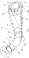
- FIG. 1 shows in a perspective, partially transparent view of a cutting device 10 for comminuting pasty substances with a nozzle 20 having a nozzle housing 21.
- the nozzle housing 21 is formed as a pipe with a bend.
- the nozzle 20 has one in the inlet 22 with an inlet flow cross-section 23, which is shown slightly offset for better representation.
- the pasty material to be comminuted is conveyed through the flow channel 26 formed in the nozzle housing 21 in the direction of an outlet 24 with an outlet flow cross-section 25. This can be done by a pump or the like, which is connected to the nozzle 20 and upstream of the cutting device 10.
- a rotating cutting tool 30 with four cutting edges 31 is arranged.
- the cutting tool 30 is driven via a drive shaft 52, which is led out of the nozzle housing 21 in the region of the bend.
- the drive shaft is mounted within the flow channel 26 in a central body 28, which forms the outlet flow cross-section 25 together with an inner wall 29 of the nozzle housing 21.
- the central body 28 extends from the outlet 24 in the flow channel 26 counter to the conveying direction.
- the central body 28 is conically shaped and has on its lateral surface on a web 281 which bears against the inner wall 29 of the nozzle housing 21.
- an extension which is up to the Inner wall 29 extends and terminates there or in, so that a continuous or almost continuous transition from the substantially circular inlet flow cross-section 23 takes place to the formed as an interrupted annular gap 27 outlet flow cross-section.
- the extension may be made separately from the conical central body 28, preferably the central body 28 forms an insert or indentation which, without further internals, rearranges the flow of material from the inlet 22 to the outlet 24 without splitting it into two separate streams.
- projections 271 on the central body 28 can also project from the outside, that is to say from the inner wall 29 of the nozzle housing 21, into the outlet flow cross-section.
- projections can also be manufactured separately and attached to the nozzle housing 21 via an attachment, attachment ring or insert. Alternatively, such projections may also be integrally formed.
- FIG. 2 shows the cutting device according to FIG. 1 in a sectional view.
- the inlet 22 and the outlet 24 are formed at opposite ends of the nozzle 20.
- the central body 28 is arranged, which has a substantially conical contour.
- the drive shaft 52 is guided, which drives the cutting tool 30 with the blades 31.
- the blades 31 completely sweep the outlet flow section 25, which is in the form of an interrupted annular gap.
- the drive shaft 25 is sealed relative to the transported material in the flow channel 26 stored so that an outside of the nozzle housing 21 arranged motor drive can not come into contact with the pasty substance.
- FIG. 2 It will be noted that the blades 31 are spaced from the nozzle 20 at the outlet 24 and thus do not abut or slide along the housing 21 or the center body. It is only the pasty material is cut by the cutting, so that a reduction in wear can be achieved.
- the central body 28 is shown as a separate component which is inserted into the nozzle housing 21 and fixed thereto.
- a web 281 is integrally formed or arranged, which ensures that in the region of the outlet 24, the outlet flow cross-section is formed as a broken annular gap, in the illustrated embodiment as a circular, interrupted annular gap.
- annular gap shapes such as polygonal shapes or oval shapes.
- nozzle 20 with the central body 28 can also be formed in one piece, for example in a casting process or in a forming process in which a first tubular base part taken as a nozzle housing 21 and the central body 28 is bent or formed inwardly ,
- the nozzle housing 21 is circumferentially enlarged over the conveying direction in the direction of the outlet 24, so that the pasty medium is not jammed within the nozzle 20.
- the central body 28 extends from the inner wall 29 in the direction of the flow channel 26 and in the conveying direction volume enlarging, preferably continuous volumenverellornd and projects into the flow channel, the material flow is relocated adjacent to the inner wall 29 and the outer contour of the central body 28 and reshaped, until the shape of the outlet flow cross section 25 is reached.
- FIG. 3 a variant of a possible outlet opening is shown as an interrupted annular gap 27.
- the outlet flow cross section 25 is formed by the outer contour of the central body 28 and the inner wall 29 of the nozzle housing 21. Via the web 281, the annular shape of the gap is interrupted.
- the end contours of the annular gap 27 are formed by the shape of the web 28.
- the length of the shaped body to be produced is essentially defined by the length of the annular gap or the radian measure of the interrupted outlet opening.
- FIG. 4 a variant shown in which the web 281 forms different circular radii R1, R2.
- the output radius R1 is smaller than the final radius R2 when the cutting element, not shown, rotates in the direction of the arrow.
- the radius changes from the initial radius R1 to the final radius R2 in the illustrated exemplary embodiment, so that a spiral-like shape of the molded article produced is obtained after truncation results.
- a continuous change of the radius makes sense. In principle, however, deviating shapes of the annular gap 27 or of the interrupted annular gap 27 can also be used.
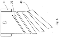
- FIG. 5 shows two views of the molding 40 or pellets obtained by the cutting process.
- the pasty material was through an annular gap, as shown in the FIG. 3 is shown pressed through and cut transversely to the exit direction of the rotary cutting tool 30.
- the result is an interrupted, annularly bent parallelepiped, in which the length is defined essentially by the length of the annular gap.
- the molding has two end faces 41, which are formed by the web 281, at which the material flow of the pasty material separated from each other and bent out of the outlet 24 is pushed out.
- the cross section of the end faces is a parallelepiped, a total of four longitudinal sides are present, an outer side 49, which abuts the outlet on the inner side 29 of the nozzle housing 21.
- the shape of the molded body 40 is first dependent on the shape of the annular gap 27 or the outlet flow cross-section 25. If an attachment or inserts are present within the outlet flow cross-section 25, over predetermined elements, such as cutting predetermined breaking points 47 or indentations in the outer long side 49 or the inner long side 48 are incorporated.
- the thickness of the space body 40 is determined in particular by the flow rate of the pasty substance and the number of revolutions of the cutting tool together with the number of cutting edges 31 and their orientation and arrangement on the circumference influenced by the cutting tool.
- the cut surfaces 43 of the shaped bodies 40 are not located on the end faces 41 but on the longitudinal sides 43 of the pellets.
- saber-type cutting edges 31 are arranged, over which the material pressed through the outlet 24 is cut transversely to the outflow direction and along the long extension of the respective shaped bodies 40 produced.
- the nozzle housing 21 and the central body 28 are formed as separate components and joined together.
- the outlet flow cross section is formed by the outer contour of the central body 28 and the inner contour of the inner surface 29 of the nozzle housing at the outlet 24.
- FIG. 8 shows a perspective sectional view of FIG. 7 in that it can be seen that the cone-shaped central body 28 increases continuously from a passage area through the inner wall 29 near the inlet 22 in the direction of the outlet 24, so that the cross-sectional shape of the inlet cross-section 23 changes continuously until an interrupted annular gap is generated ,
- the longitudinal axis of the cone is not collinear with the longitudinal axis or center axis of the nozzle housing 21 in the outlet region, so that over the length of the flow channel changing, not rotationally symmetrical flow cross-sectional shapes result.
- Within the flow channel 26 no separation or division takes place into two separate streams of material transported through, but the transported material is rearranged and reshaped until it is brought into a curved, flat shape.
- a separation of the two ends of the annular gap takes place.
- a helical division of the pasty medium is then made.
- a separation in the length can be done via the introduced predetermined breaking points in the further processing of the formed blanks.
- FIG. 9 shows the cutting device in a partially assembled state, in which only the nozzle housing 21 with the central body 28 and on the lateral surface of the cone-shaped central body 28 integrally molded web 281 can be seen.
- the central body 28 is connected via a slot, as shown for example in the FIG. 11 designated by the reference numeral 218, inserted into the housing.
- the web 281 protrudes through the nozzle housing 21.
- different variants of the central body 28 can be coupled to a nozzle housing 21 as a base body. Likewise, worn components can be replaced more easily.
- FIG. 10 shows the mounting condition according to FIG. 9 in a rear view from the inlet side. It can be seen that the central body 28 with the conical basic shape penetrates the wall of the nozzle housing 21. Material flowing from the inlet side to the outlet side is moved around the central body 28 at the penetration site and contacts the inner wall 29 of the nozzle housing 21 and the outer wall of the central body 28 and around the central body 28 without material flow separation. Within the central body 28, a bore 285 for receiving the drive shaft 52 is incorporated.
- FIG. 11 shows the nozzle housing 21 in a single view with the in the conveying direction extending to the outlet 24 slot 218.
- the slot 218 is shaped so that the web 281 is closely received and the conical central body 28 fits snugly against the nozzle housing 21, so that a dense completion and a continuous as possible transition from the inner wall 29 of the nozzle housing to the conical central body 28 takes place.
Landscapes
- Engineering & Computer Science (AREA)
- Mechanical Engineering (AREA)
- Manufacturing & Machinery (AREA)
- Life Sciences & Earth Sciences (AREA)
- Forests & Forestry (AREA)
- Chemical & Material Sciences (AREA)
- Food Science & Technology (AREA)
- Polymers & Plastics (AREA)
- Organic Chemistry (AREA)
- Chemical Kinetics & Catalysis (AREA)
- Processing And Handling Of Plastics And Other Materials For Molding In General (AREA)
- Crushing And Pulverization Processes (AREA)
- Crushing And Grinding (AREA)
- Formation And Processing Of Food Products (AREA)
- Details Of Cutting Devices (AREA)
Priority Applications (1)
| Application Number | Priority Date | Filing Date | Title |
|---|---|---|---|
| PL18191208T PL3459701T3 (pl) | 2017-08-31 | 2018-08-28 | Urządzenie tnące do rozdrabniania substancji o konsystencji pasty |
Applications Claiming Priority (1)
| Application Number | Priority Date | Filing Date | Title |
|---|---|---|---|
| DE102017120047.9A DE102017120047B4 (de) | 2017-08-31 | 2017-08-31 | Schneidvorrichtung, System mit einer Schneidvorrichtung und einer Weiterverarbeitungseinrichtung sowie Verfahren zum Zerkleinern von pastösen Stoffen |
Publications (3)
| Publication Number | Publication Date |
|---|---|
| EP3459701A2 true EP3459701A2 (fr) | 2019-03-27 |
| EP3459701A3 EP3459701A3 (fr) | 2019-06-05 |
| EP3459701B1 EP3459701B1 (fr) | 2021-11-03 |
Family
ID=63442487
Family Applications (1)
| Application Number | Title | Priority Date | Filing Date |
|---|---|---|---|
| EP18191208.0A Active EP3459701B1 (fr) | 2017-08-31 | 2018-08-28 | Dispositif de coupe pour découper des matières pâteuses |
Country Status (7)
| Country | Link |
|---|---|
| US (1) | US20190061192A1 (fr) |
| EP (1) | EP3459701B1 (fr) |
| JP (1) | JP2019048373A (fr) |
| CN (1) | CN109433371A (fr) |
| DE (1) | DE102017120047B4 (fr) |
| DK (1) | DK3459701T3 (fr) |
| PL (1) | PL3459701T3 (fr) |
Families Citing this family (2)
| Publication number | Priority date | Publication date | Assignee | Title |
|---|---|---|---|---|
| DE102022002368A1 (de) | 2022-06-30 | 2024-01-04 | Universität Düsseldorf. Körperschaft des öffentlichen Rechts | Schneidevorrichtung und Schneideverfahren für Schnittstücke von Extrudaten unterschiedlicher Länge |
| CN117322343B (zh) * | 2023-11-22 | 2025-07-04 | 山东安然纳米实业发展有限公司 | 一种具有导流罩的裁切结构及其植物组织培养罐 |
Family Cites Families (8)
| Publication number | Priority date | Publication date | Assignee | Title |
|---|---|---|---|---|
| US1987358A (en) | 1932-09-06 | 1935-01-08 | Bonnot Company | Method and apparatus for plastic material manufacture |
| US3025565A (en) * | 1958-05-28 | 1962-03-20 | Wacker Chemie Gmbh | Process and apparatus for granulating and forming plastic masses |
| DE3518323A1 (de) | 1985-05-22 | 1986-11-27 | SEVAR Entsorgungsanlagen GmbH, 8590 Marktredwitz | Verfahren und vorrichtung zum trocknen von klaerschlamm |
| DE4013760A1 (de) | 1990-04-28 | 1991-10-31 | Sevar Entsorgung | Einrichtung zum formen wuerstchenfoermiger formlinge aus pastoesem schlammaterial |
| DE19617972B4 (de) | 1996-05-06 | 2005-02-10 | Alb. Klein Umwelttechnik Gmbh | Vorrichtung und Verfahren zum Pelletieren von Schlamm |
| DE19710302A1 (de) | 1997-02-28 | 1998-09-03 | Bech Ulrich Dipl Ing | Schlamm-Schredder |
| DE19813485A1 (de) | 1998-03-26 | 1999-09-30 | Sep Tech Studien | Zerkleinerungs- und Zuteilungsvorrichtung für zerstückelbare, pumpbare Stoffe |
| CH704751B1 (de) | 2004-07-21 | 2012-10-15 | Buss Ag | Schneidvorrichtung für zähplastische Materialien sowie Verfahren zum Betrieb der Schneidvorrichtung. |
-
2017
- 2017-08-31 DE DE102017120047.9A patent/DE102017120047B4/de active Active
-
2018
- 2018-08-17 JP JP2018153355A patent/JP2019048373A/ja active Pending
- 2018-08-28 EP EP18191208.0A patent/EP3459701B1/fr active Active
- 2018-08-28 US US16/114,277 patent/US20190061192A1/en not_active Abandoned
- 2018-08-28 DK DK18191208.0T patent/DK3459701T3/da active
- 2018-08-28 PL PL18191208T patent/PL3459701T3/pl unknown
- 2018-08-30 CN CN201811001469.1A patent/CN109433371A/zh active Pending
Also Published As
| Publication number | Publication date |
|---|---|
| PL3459701T3 (pl) | 2022-02-21 |
| JP2019048373A (ja) | 2019-03-28 |
| EP3459701B1 (fr) | 2021-11-03 |
| CN109433371A (zh) | 2019-03-08 |
| EP3459701A3 (fr) | 2019-06-05 |
| DE102017120047A1 (de) | 2019-02-28 |
| DE102017120047B4 (de) | 2021-07-08 |
| US20190061192A1 (en) | 2019-02-28 |
| DK3459701T3 (da) | 2022-01-31 |
Similar Documents
| Publication | Publication Date | Title |
|---|---|---|
| DE1457182C3 (de) | Vorrichtung zum kontinuierlichen Mischen | |
| EP1931951B1 (fr) | Dispositif de dosage pour substances pulverulentes ou pateuses | |
| EP1815958B1 (fr) | Mélangeur pétrisseur | |
| EP1631371B1 (fr) | Dispositif pour le traitement de solides | |
| EP2766163B1 (fr) | Dispositif pour préparer une matière plastique | |
| EP0652824B1 (fr) | Extrudeuse a vis | |
| EP2755769B1 (fr) | Dispositif de mélangeage | |
| WO2019007756A1 (fr) | Dispositif et procédé pour l'extrusion de matériaux en vrac pouvant subir une déformation thermo-mécanique, et extrudeuse à vis de type compact | |
| WO2019076631A1 (fr) | Arbre à vis sans fin à deux ailes pour machine de mélange et de malaxage | |
| EP3459701B1 (fr) | Dispositif de coupe pour découper des matières pâteuses | |
| AT511564A1 (de) | Mischvorrichtung und verfahren zum mischen eines schüttgutes oder einer pastösen masse | |
| EP3964069B1 (fr) | Unité de traitement de la pâte, ainsi que dispositif et procédé de traitement de la pâte | |
| DE2537915C3 (de) | Misch- und Knetvorrichtung für «ine Strangpresse zum Plastifizieren von thermoplastischen Kunststoffen | |
| EP0428978B1 (fr) | Dispositif d'extrusion | |
| DE1145787B (de) | Schneckenstrangpresse mit einem Stauabschnitt, dessen Querschnitt veraenderlich ist | |
| DE1288297B (de) | Extrusionseinrichtung zum Herstellen von Schlaeuchen aus thermoplastischem Material | |
| EP2584322A1 (fr) | Rouleau doseur, dispositifs de dosage et procédé de dosage pour particules de marchandises en vrac | |
| DE1937547A1 (de) | Verfahren und Vorrichtung zum Granulieren von duroplastischen Pressmassen | |
| EP1771500B1 (fr) | Procede de melange de granules plastiques avec un additif, dispositif de melange permettant de mettre en oeuvre ce procede et systeme comprenant ce dispositif | |
| EP3941701B1 (fr) | Vis sans fin avec partie coupée à l'arrière pour extrudeuse ou transporteur | |
| EP2654437B1 (fr) | Dispositif à pétrir pour pétrir et mélanger de la pâte | |
| EP2501531B1 (fr) | Appareil pour granuler | |
| EP3300793B1 (fr) | Dispositif de mélange d'un article en poudre avec un liquide | |
| DE19754873A1 (de) | Extrusionsvorrichtung | |
| DE1949836B2 (de) | Plastifizier- und knetvorrichtung fuer plastifizierbares gut, insbesondere kunststoffe |
Legal Events
| Date | Code | Title | Description |
|---|---|---|---|
| PUAI | Public reference made under article 153(3) epc to a published international application that has entered the european phase |
Free format text: ORIGINAL CODE: 0009012 |
|
| STAA | Information on the status of an ep patent application or granted ep patent |
Free format text: STATUS: THE APPLICATION HAS BEEN PUBLISHED |
|
| AK | Designated contracting states |
Kind code of ref document: A2 Designated state(s): AL AT BE BG CH CY CZ DE DK EE ES FI FR GB GR HR HU IE IS IT LI LT LU LV MC MK MT NL NO PL PT RO RS SE SI SK SM TR |
|
| AX | Request for extension of the european patent |
Extension state: BA ME |
|
| PUAL | Search report despatched |
Free format text: ORIGINAL CODE: 0009013 |
|
| AK | Designated contracting states |
Kind code of ref document: A3 Designated state(s): AL AT BE BG CH CY CZ DE DK EE ES FI FR GB GR HR HU IE IS IT LI LT LU LV MC MK MT NL NO PL PT RO RS SE SI SK SM TR |
|
| AX | Request for extension of the european patent |
Extension state: BA ME |
|
| RIC1 | Information provided on ipc code assigned before grant |
Ipc: B29B 9/06 20060101AFI20190429BHEP Ipc: B29C 48/33 20190101ALI20190429BHEP Ipc: B29C 48/04 20190101ALN20190429BHEP |
|
| STAA | Information on the status of an ep patent application or granted ep patent |
Free format text: STATUS: REQUEST FOR EXAMINATION WAS MADE |
|
| 17P | Request for examination filed |
Effective date: 20191204 |
|
| RBV | Designated contracting states (corrected) |
Designated state(s): AL AT BE BG CH CY CZ DE DK EE ES FI FR GB GR HR HU IE IS IT LI LT LU LV MC MK MT NL NO PL PT RO RS SE SI SK SM TR |
|
| GRAP | Despatch of communication of intention to grant a patent |
Free format text: ORIGINAL CODE: EPIDOSNIGR1 |
|
| STAA | Information on the status of an ep patent application or granted ep patent |
Free format text: STATUS: GRANT OF PATENT IS INTENDED |
|
| RIC1 | Information provided on ipc code assigned before grant |
Ipc: A23P 30/10 20160101ALN20210604BHEP Ipc: B26D 1/28 20060101ALN20210604BHEP Ipc: B26D 1/36 20060101ALN20210604BHEP Ipc: B29C 48/04 20190101ALN20210604BHEP Ipc: B29C 48/30 20190101ALI20210604BHEP Ipc: B29C 48/33 20190101ALI20210604BHEP Ipc: B29B 9/06 20060101AFI20210604BHEP |
|
| INTG | Intention to grant announced |
Effective date: 20210622 |
|
| GRAS | Grant fee paid |
Free format text: ORIGINAL CODE: EPIDOSNIGR3 |
|
| GRAA | (expected) grant |
Free format text: ORIGINAL CODE: 0009210 |
|
| STAA | Information on the status of an ep patent application or granted ep patent |
Free format text: STATUS: THE PATENT HAS BEEN GRANTED |
|
| AK | Designated contracting states |
Kind code of ref document: B1 Designated state(s): AL AT BE BG CH CY CZ DE DK EE ES FI FR GB GR HR HU IE IS IT LI LT LU LV MC MK MT NL NO PL PT RO RS SE SI SK SM TR |
|
| REG | Reference to a national code |
Ref country code: GB Ref legal event code: FG4D Free format text: NOT ENGLISH |
|
| REG | Reference to a national code |
Ref country code: AT Ref legal event code: REF Ref document number: 1443575 Country of ref document: AT Kind code of ref document: T Effective date: 20211115 Ref country code: CH Ref legal event code: EP |
|
| REG | Reference to a national code |
Ref country code: IE Ref legal event code: FG4D Free format text: LANGUAGE OF EP DOCUMENT: GERMAN |
|
| REG | Reference to a national code |
Ref country code: DE Ref legal event code: R096 Ref document number: 502018007657 Country of ref document: DE |
|
| REG | Reference to a national code |
Ref country code: DK Ref legal event code: T3 Effective date: 20220124 |
|
| REG | Reference to a national code |
Ref country code: NL Ref legal event code: FP |
|
| REG | Reference to a national code |
Ref country code: LT Ref legal event code: MG9D |
|
| PG25 | Lapsed in a contracting state [announced via postgrant information from national office to epo] |
Ref country code: RS Free format text: LAPSE BECAUSE OF FAILURE TO SUBMIT A TRANSLATION OF THE DESCRIPTION OR TO PAY THE FEE WITHIN THE PRESCRIBED TIME-LIMIT Effective date: 20211103 Ref country code: LT Free format text: LAPSE BECAUSE OF FAILURE TO SUBMIT A TRANSLATION OF THE DESCRIPTION OR TO PAY THE FEE WITHIN THE PRESCRIBED TIME-LIMIT Effective date: 20211103 Ref country code: FI Free format text: LAPSE BECAUSE OF FAILURE TO SUBMIT A TRANSLATION OF THE DESCRIPTION OR TO PAY THE FEE WITHIN THE PRESCRIBED TIME-LIMIT Effective date: 20211103 Ref country code: BG Free format text: LAPSE BECAUSE OF FAILURE TO SUBMIT A TRANSLATION OF THE DESCRIPTION OR TO PAY THE FEE WITHIN THE PRESCRIBED TIME-LIMIT Effective date: 20220203 |
|
| PG25 | Lapsed in a contracting state [announced via postgrant information from national office to epo] |
Ref country code: IS Free format text: LAPSE BECAUSE OF FAILURE TO SUBMIT A TRANSLATION OF THE DESCRIPTION OR TO PAY THE FEE WITHIN THE PRESCRIBED TIME-LIMIT Effective date: 20220303 Ref country code: SE Free format text: LAPSE BECAUSE OF FAILURE TO SUBMIT A TRANSLATION OF THE DESCRIPTION OR TO PAY THE FEE WITHIN THE PRESCRIBED TIME-LIMIT Effective date: 20211103 Ref country code: PT Free format text: LAPSE BECAUSE OF FAILURE TO SUBMIT A TRANSLATION OF THE DESCRIPTION OR TO PAY THE FEE WITHIN THE PRESCRIBED TIME-LIMIT Effective date: 20220303 Ref country code: NO Free format text: LAPSE BECAUSE OF FAILURE TO SUBMIT A TRANSLATION OF THE DESCRIPTION OR TO PAY THE FEE WITHIN THE PRESCRIBED TIME-LIMIT Effective date: 20220203 Ref country code: LV Free format text: LAPSE BECAUSE OF FAILURE TO SUBMIT A TRANSLATION OF THE DESCRIPTION OR TO PAY THE FEE WITHIN THE PRESCRIBED TIME-LIMIT Effective date: 20211103 Ref country code: HR Free format text: LAPSE BECAUSE OF FAILURE TO SUBMIT A TRANSLATION OF THE DESCRIPTION OR TO PAY THE FEE WITHIN THE PRESCRIBED TIME-LIMIT Effective date: 20211103 Ref country code: GR Free format text: LAPSE BECAUSE OF FAILURE TO SUBMIT A TRANSLATION OF THE DESCRIPTION OR TO PAY THE FEE WITHIN THE PRESCRIBED TIME-LIMIT Effective date: 20220204 Ref country code: ES Free format text: LAPSE BECAUSE OF FAILURE TO SUBMIT A TRANSLATION OF THE DESCRIPTION OR TO PAY THE FEE WITHIN THE PRESCRIBED TIME-LIMIT Effective date: 20211103 |
|
| PG25 | Lapsed in a contracting state [announced via postgrant information from national office to epo] |
Ref country code: SM Free format text: LAPSE BECAUSE OF FAILURE TO SUBMIT A TRANSLATION OF THE DESCRIPTION OR TO PAY THE FEE WITHIN THE PRESCRIBED TIME-LIMIT Effective date: 20211103 Ref country code: SK Free format text: LAPSE BECAUSE OF FAILURE TO SUBMIT A TRANSLATION OF THE DESCRIPTION OR TO PAY THE FEE WITHIN THE PRESCRIBED TIME-LIMIT Effective date: 20211103 Ref country code: RO Free format text: LAPSE BECAUSE OF FAILURE TO SUBMIT A TRANSLATION OF THE DESCRIPTION OR TO PAY THE FEE WITHIN THE PRESCRIBED TIME-LIMIT Effective date: 20211103 Ref country code: EE Free format text: LAPSE BECAUSE OF FAILURE TO SUBMIT A TRANSLATION OF THE DESCRIPTION OR TO PAY THE FEE WITHIN THE PRESCRIBED TIME-LIMIT Effective date: 20211103 Ref country code: CZ Free format text: LAPSE BECAUSE OF FAILURE TO SUBMIT A TRANSLATION OF THE DESCRIPTION OR TO PAY THE FEE WITHIN THE PRESCRIBED TIME-LIMIT Effective date: 20211103 |
|
| REG | Reference to a national code |
Ref country code: DE Ref legal event code: R097 Ref document number: 502018007657 Country of ref document: DE |
|
| PLBE | No opposition filed within time limit |
Free format text: ORIGINAL CODE: 0009261 |
|
| STAA | Information on the status of an ep patent application or granted ep patent |
Free format text: STATUS: NO OPPOSITION FILED WITHIN TIME LIMIT |
|
| 26N | No opposition filed |
Effective date: 20220804 |
|
| PG25 | Lapsed in a contracting state [announced via postgrant information from national office to epo] |
Ref country code: AL Free format text: LAPSE BECAUSE OF FAILURE TO SUBMIT A TRANSLATION OF THE DESCRIPTION OR TO PAY THE FEE WITHIN THE PRESCRIBED TIME-LIMIT Effective date: 20211103 |
|
| PG25 | Lapsed in a contracting state [announced via postgrant information from national office to epo] |
Ref country code: SI Free format text: LAPSE BECAUSE OF FAILURE TO SUBMIT A TRANSLATION OF THE DESCRIPTION OR TO PAY THE FEE WITHIN THE PRESCRIBED TIME-LIMIT Effective date: 20211103 |
|
| PG25 | Lapsed in a contracting state [announced via postgrant information from national office to epo] |
Ref country code: MC Free format text: LAPSE BECAUSE OF FAILURE TO SUBMIT A TRANSLATION OF THE DESCRIPTION OR TO PAY THE FEE WITHIN THE PRESCRIBED TIME-LIMIT Effective date: 20211103 |
|
| REG | Reference to a national code |
Ref country code: CH Ref legal event code: PL |
|
| PG25 | Lapsed in a contracting state [announced via postgrant information from national office to epo] |
Ref country code: LU Free format text: LAPSE BECAUSE OF NON-PAYMENT OF DUE FEES Effective date: 20220828 Ref country code: LI Free format text: LAPSE BECAUSE OF NON-PAYMENT OF DUE FEES Effective date: 20220831 Ref country code: CH Free format text: LAPSE BECAUSE OF NON-PAYMENT OF DUE FEES Effective date: 20220831 |
|
| REG | Reference to a national code |
Ref country code: BE Ref legal event code: MM Effective date: 20220831 |
|
| PG25 | Lapsed in a contracting state [announced via postgrant information from national office to epo] |
Ref country code: IT Free format text: LAPSE BECAUSE OF FAILURE TO SUBMIT A TRANSLATION OF THE DESCRIPTION OR TO PAY THE FEE WITHIN THE PRESCRIBED TIME-LIMIT Effective date: 20211103 |
|
| P01 | Opt-out of the competence of the unified patent court (upc) registered |
Effective date: 20230605 |
|
| PG25 | Lapsed in a contracting state [announced via postgrant information from national office to epo] |
Ref country code: IE Free format text: LAPSE BECAUSE OF NON-PAYMENT OF DUE FEES Effective date: 20220828 |
|
| PG25 | Lapsed in a contracting state [announced via postgrant information from national office to epo] |
Ref country code: BE Free format text: LAPSE BECAUSE OF NON-PAYMENT OF DUE FEES Effective date: 20220831 |
|
| PG25 | Lapsed in a contracting state [announced via postgrant information from national office to epo] |
Ref country code: HU Free format text: LAPSE BECAUSE OF FAILURE TO SUBMIT A TRANSLATION OF THE DESCRIPTION OR TO PAY THE FEE WITHIN THE PRESCRIBED TIME-LIMIT; INVALID AB INITIO Effective date: 20180828 |
|
| PG25 | Lapsed in a contracting state [announced via postgrant information from national office to epo] |
Ref country code: CY Free format text: LAPSE BECAUSE OF FAILURE TO SUBMIT A TRANSLATION OF THE DESCRIPTION OR TO PAY THE FEE WITHIN THE PRESCRIBED TIME-LIMIT Effective date: 20211103 |
|
| PG25 | Lapsed in a contracting state [announced via postgrant information from national office to epo] |
Ref country code: MK Free format text: LAPSE BECAUSE OF FAILURE TO SUBMIT A TRANSLATION OF THE DESCRIPTION OR TO PAY THE FEE WITHIN THE PRESCRIBED TIME-LIMIT Effective date: 20211103 |
|
| REG | Reference to a national code |
Ref country code: DE Ref legal event code: R081 Ref document number: 502018007657 Country of ref document: DE Owner name: BMA BRAUNSCHWEIGISCHE MASCHINENBAUANSTALT GMBH, DE Free format text: FORMER OWNER: BMA BRAUNSCHWEIGISCHE MASCHINENBAUANSTALT AG, 38122 BRAUNSCHWEIG, DE |
|
| PG25 | Lapsed in a contracting state [announced via postgrant information from national office to epo] |
Ref country code: TR Free format text: LAPSE BECAUSE OF FAILURE TO SUBMIT A TRANSLATION OF THE DESCRIPTION OR TO PAY THE FEE WITHIN THE PRESCRIBED TIME-LIMIT Effective date: 20211103 |
|
| REG | Reference to a national code |
Ref country code: NL Ref legal event code: PD Owner name: BMA BRAUNSCHWEIGISCHE MASCHINENBAUANSTALT GMBH; DE Free format text: DETAILS ASSIGNMENT: CHANGE OF OWNER(S), CHANGE OF LEGAL ENTITY; FORMER OWNER NAME: BMA BRAUNSCHWEIGISCHE MASCHINENBAUANSTALT AG Effective date: 20240624 |
|
| PG25 | Lapsed in a contracting state [announced via postgrant information from national office to epo] |
Ref country code: MT Free format text: LAPSE BECAUSE OF FAILURE TO SUBMIT A TRANSLATION OF THE DESCRIPTION OR TO PAY THE FEE WITHIN THE PRESCRIBED TIME-LIMIT Effective date: 20211103 |
|
| REG | Reference to a national code |
Ref country code: AT Ref legal event code: MM01 Ref document number: 1443575 Country of ref document: AT Kind code of ref document: T Effective date: 20230828 |
|
| PG25 | Lapsed in a contracting state [announced via postgrant information from national office to epo] |
Ref country code: AT Free format text: LAPSE BECAUSE OF NON-PAYMENT OF DUE FEES Effective date: 20230828 |
|
| PG25 | Lapsed in a contracting state [announced via postgrant information from national office to epo] |
Ref country code: AT Free format text: LAPSE BECAUSE OF NON-PAYMENT OF DUE FEES Effective date: 20230828 |
|
| PGFP | Annual fee paid to national office [announced via postgrant information from national office to epo] |
Ref country code: NL Payment date: 20250821 Year of fee payment: 8 |
|
| PGFP | Annual fee paid to national office [announced via postgrant information from national office to epo] |
Ref country code: DE Payment date: 20250819 Year of fee payment: 8 Ref country code: DK Payment date: 20250821 Year of fee payment: 8 |
|
| PGFP | Annual fee paid to national office [announced via postgrant information from national office to epo] |
Ref country code: PL Payment date: 20250825 Year of fee payment: 8 |
|
| PGFP | Annual fee paid to national office [announced via postgrant information from national office to epo] |
Ref country code: GB Payment date: 20250822 Year of fee payment: 8 |
|
| PGFP | Annual fee paid to national office [announced via postgrant information from national office to epo] |
Ref country code: FR Payment date: 20250827 Year of fee payment: 8 |