EP3459468B1 - Method and system for arranging objects in an operating room - Google Patents
Method and system for arranging objects in an operating room Download PDFInfo
- Publication number
- EP3459468B1 EP3459468B1 EP18204774.6A EP18204774A EP3459468B1 EP 3459468 B1 EP3459468 B1 EP 3459468B1 EP 18204774 A EP18204774 A EP 18204774A EP 3459468 B1 EP3459468 B1 EP 3459468B1
- Authority
- EP
- European Patent Office
- Prior art keywords
- placement
- mobile cart
- operating room
- guidance station
- trackers
- Prior art date
- Legal status (The legal status is an assumption and is not a legal conclusion. Google has not performed a legal analysis and makes no representation as to the accuracy of the status listed.)
- Active
Links
- 238000000034 method Methods 0.000 title claims description 60
- 238000001356 surgical procedure Methods 0.000 claims description 32
- 210000000988 bone and bone Anatomy 0.000 claims description 23
- 230000033001 locomotion Effects 0.000 claims description 18
- 230000000007 visual effect Effects 0.000 claims description 17
- 238000004891 communication Methods 0.000 claims description 8
- 238000003754 machining Methods 0.000 description 24
- 238000005520 cutting process Methods 0.000 description 19
- 239000007943 implant Substances 0.000 description 18
- 230000003287 optical effect Effects 0.000 description 16
- 210000003484 anatomy Anatomy 0.000 description 15
- 210000002414 leg Anatomy 0.000 description 14
- 210000002303 tibia Anatomy 0.000 description 12
- 210000000689 upper leg Anatomy 0.000 description 12
- 238000013461 design Methods 0.000 description 9
- 210000003127 knee Anatomy 0.000 description 7
- 230000004807 localization Effects 0.000 description 6
- 230000001276 controlling effect Effects 0.000 description 5
- 238000010586 diagram Methods 0.000 description 5
- 210000001519 tissue Anatomy 0.000 description 5
- 230000007704 transition Effects 0.000 description 5
- 210000000629 knee joint Anatomy 0.000 description 4
- 238000013150 knee replacement Methods 0.000 description 4
- 230000008901 benefit Effects 0.000 description 3
- 238000001444 catalytic combustion detection Methods 0.000 description 3
- 239000012636 effector Substances 0.000 description 3
- 210000004417 patella Anatomy 0.000 description 3
- 238000012545 processing Methods 0.000 description 3
- 238000005070 sampling Methods 0.000 description 3
- 238000004088 simulation Methods 0.000 description 3
- 206010002091 Anaesthesia Diseases 0.000 description 2
- 230000037005 anaesthesia Effects 0.000 description 2
- 238000004458 analytical method Methods 0.000 description 2
- 238000002591 computed tomography Methods 0.000 description 2
- 230000000875 corresponding effect Effects 0.000 description 2
- 230000001934 delay Effects 0.000 description 2
- 210000003414 extremity Anatomy 0.000 description 2
- 238000011540 hip replacement Methods 0.000 description 2
- 238000003384 imaging method Methods 0.000 description 2
- 210000001503 joint Anatomy 0.000 description 2
- 239000000463 material Substances 0.000 description 2
- 238000002360 preparation method Methods 0.000 description 2
- 238000012552 review Methods 0.000 description 2
- 238000012546 transfer Methods 0.000 description 2
- 238000002679 ablation Methods 0.000 description 1
- 230000003466 anti-cipated effect Effects 0.000 description 1
- 230000002596 correlated effect Effects 0.000 description 1
- 230000008878 coupling Effects 0.000 description 1
- 238000010168 coupling process Methods 0.000 description 1
- 238000005859 coupling reaction Methods 0.000 description 1
- 238000005516 engineering process Methods 0.000 description 1
- 210000001624 hip Anatomy 0.000 description 1
- 210000004394 hip joint Anatomy 0.000 description 1
- 238000002513 implantation Methods 0.000 description 1
- 238000004519 manufacturing process Methods 0.000 description 1
- 230000007246 mechanism Effects 0.000 description 1
- 239000002184 metal Substances 0.000 description 1
- 238000012986 modification Methods 0.000 description 1
- 230000004048 modification Effects 0.000 description 1
- 230000000399 orthopedic effect Effects 0.000 description 1
- 210000004872 soft tissue Anatomy 0.000 description 1
- 238000003860 storage Methods 0.000 description 1
- 230000009466 transformation Effects 0.000 description 1
Images


Classifications
-
- A—HUMAN NECESSITIES
- A61—MEDICAL OR VETERINARY SCIENCE; HYGIENE
- A61B—DIAGNOSIS; SURGERY; IDENTIFICATION
- A61B34/00—Computer-aided surgery; Manipulators or robots specially adapted for use in surgery
- A61B34/20—Surgical navigation systems; Devices for tracking or guiding surgical instruments, e.g. for frameless stereotaxis
-
- A—HUMAN NECESSITIES
- A61—MEDICAL OR VETERINARY SCIENCE; HYGIENE
- A61B—DIAGNOSIS; SURGERY; IDENTIFICATION
- A61B17/00—Surgical instruments, devices or methods, e.g. tourniquets
- A61B17/14—Surgical saws ; Accessories therefor
- A61B17/15—Guides therefor
- A61B17/154—Guides therefor for preparing bone for knee prosthesis
-
- A—HUMAN NECESSITIES
- A61—MEDICAL OR VETERINARY SCIENCE; HYGIENE
- A61B—DIAGNOSIS; SURGERY; IDENTIFICATION
- A61B17/00—Surgical instruments, devices or methods, e.g. tourniquets
- A61B17/16—Bone cutting, breaking or removal means other than saws, e.g. Osteoclasts; Drills or chisels for bones; Trepans
- A61B17/17—Guides or aligning means for drills, mills, pins or wires
- A61B17/1739—Guides or aligning means for drills, mills, pins or wires specially adapted for particular parts of the body
- A61B17/1742—Guides or aligning means for drills, mills, pins or wires specially adapted for particular parts of the body for the hip
-
- A—HUMAN NECESSITIES
- A61—MEDICAL OR VETERINARY SCIENCE; HYGIENE
- A61B—DIAGNOSIS; SURGERY; IDENTIFICATION
- A61B17/00—Surgical instruments, devices or methods, e.g. tourniquets
- A61B17/16—Bone cutting, breaking or removal means other than saws, e.g. Osteoclasts; Drills or chisels for bones; Trepans
- A61B17/17—Guides or aligning means for drills, mills, pins or wires
- A61B17/1739—Guides or aligning means for drills, mills, pins or wires specially adapted for particular parts of the body
- A61B17/1764—Guides or aligning means for drills, mills, pins or wires specially adapted for particular parts of the body for the knee
-
- A—HUMAN NECESSITIES
- A61—MEDICAL OR VETERINARY SCIENCE; HYGIENE
- A61B—DIAGNOSIS; SURGERY; IDENTIFICATION
- A61B90/00—Instruments, implements or accessories specially adapted for surgery or diagnosis and not covered by any of the groups A61B1/00 - A61B50/00, e.g. for luxation treatment or for protecting wound edges
- A61B90/36—Image-producing devices or illumination devices not otherwise provided for
- A61B90/37—Surgical systems with images on a monitor during operation
-
- G—PHYSICS
- G16—INFORMATION AND COMMUNICATION TECHNOLOGY [ICT] SPECIALLY ADAPTED FOR SPECIFIC APPLICATION FIELDS
- G16H—HEALTHCARE INFORMATICS, i.e. INFORMATION AND COMMUNICATION TECHNOLOGY [ICT] SPECIALLY ADAPTED FOR THE HANDLING OR PROCESSING OF MEDICAL OR HEALTHCARE DATA
- G16H40/00—ICT specially adapted for the management or administration of healthcare resources or facilities; ICT specially adapted for the management or operation of medical equipment or devices
- G16H40/40—ICT specially adapted for the management or administration of healthcare resources or facilities; ICT specially adapted for the management or operation of medical equipment or devices for the management of medical equipment or devices, e.g. scheduling maintenance or upgrades
-
- A—HUMAN NECESSITIES
- A61—MEDICAL OR VETERINARY SCIENCE; HYGIENE
- A61B—DIAGNOSIS; SURGERY; IDENTIFICATION
- A61B34/00—Computer-aided surgery; Manipulators or robots specially adapted for use in surgery
- A61B34/10—Computer-aided planning, simulation or modelling of surgical operations
- A61B2034/101—Computer-aided simulation of surgical operations
- A61B2034/105—Modelling of the patient, e.g. for ligaments or bones
-
- A—HUMAN NECESSITIES
- A61—MEDICAL OR VETERINARY SCIENCE; HYGIENE
- A61B—DIAGNOSIS; SURGERY; IDENTIFICATION
- A61B34/00—Computer-aided surgery; Manipulators or robots specially adapted for use in surgery
- A61B34/10—Computer-aided planning, simulation or modelling of surgical operations
- A61B2034/107—Visualisation of planned trajectories or target regions
-
- A—HUMAN NECESSITIES
- A61—MEDICAL OR VETERINARY SCIENCE; HYGIENE
- A61B—DIAGNOSIS; SURGERY; IDENTIFICATION
- A61B34/00—Computer-aided surgery; Manipulators or robots specially adapted for use in surgery
- A61B34/20—Surgical navigation systems; Devices for tracking or guiding surgical instruments, e.g. for frameless stereotaxis
- A61B2034/2046—Tracking techniques
- A61B2034/2055—Optical tracking systems
-
- A—HUMAN NECESSITIES
- A61—MEDICAL OR VETERINARY SCIENCE; HYGIENE
- A61B—DIAGNOSIS; SURGERY; IDENTIFICATION
- A61B34/00—Computer-aided surgery; Manipulators or robots specially adapted for use in surgery
- A61B34/25—User interfaces for surgical systems
- A61B2034/252—User interfaces for surgical systems indicating steps of a surgical procedure
Definitions
- the present invention relates generally to a system and method for arranging objects in an operating room in preparation for a surgical procedure.
- objects Before starting a surgical procedure, many objects need to be properly arranged in the operating room. Such objects include equipment, the patient, surgical personnel, instruments, and the like. Proper arrangement of these objects in the operating room, before the procedure begins, helps to ensure that the surgical procedure proceeds without unnecessary delays. Traditionally, objects are arranged according to written protocols that may include operating room layouts and written instructions associated with the particular procedure being performed.
- navigation equipment such as sensing devices (e.g., tracking cameras, magnetic field sensors, etc.) and tracking devices require arrangement before the procedure starts.
- Navigation systems employ such navigation equipment to assist users in locating objects. For instance, navigation systems assist surgeons in precisely placing surgical instruments relative to a patient's anatomy.
- Surgeries in which navigation systems are used include neurosurgery and orthopedic surgery.
- the instrument and the anatomy are tracked together with their relative movement shown on a display.
- Navigation systems may employ light signals, sound waves, magnetic fields, RF signals, etc. in order to track the position and/or orientation of objects.
- Tracking devices are attached to the objects being tracked.
- a localizer which includes the sensing devices, cooperates with the tracking devices to determine a position of the tracking devices, and ultimately to determine a position and/or orientation of the objects.
- the navigation system monitors movement of the objects via the tracking devices.
- Document US 2012/0101508 describes a movement compensating device of a surgical robot in which a surgical operation processing unit mounted with a surgical instrument is coupled to one end of a body section.
- Said movement compensating device includes an image information creating unit that creates image information corresponding to an image signal supplied from a camera unit, a recognition point information analyzing unit that creates analysis information on a distance and an angle between a recognition point recognized from image information pieces corresponding to a predetermined number of image frames and a predetermined reference point, a variation analyzing unit that creates variation information in distance and angle between two analysis information pieces continuously created, and a control command creating and outputting unit that creates and outputs a control command for adjusting the position of the surgical operation processing unit so that the variation in distance and angle included in the variation information be zero.
- a system for arranging a mobile cart of a robotic system in an operating room according to surgical procedure information.
- a method for arranging a mobile cart of a robotic system in an operating room using a guidance station having a display includes providing surgical procedure information to the guidance station.
- the method further includes determining a desired placement of the mobile cart based on the procedure information, wherein the robotic system has a tracking device capable of communication with the guidance station to determine a current placement of the mobile cart. Manual placement of the mobile cart by a user is guided according to the desired placement.
- One advantage of these embodiments is to facilitate arranging objects in the operating room in an efficient manner and based on the particular procedure to be performed so that the objects are placed in desired locations for that particular procedure.
- the system includes a guidance station 20 and tracking elements associated with various objects.
- the tracking elements are capable of communicating with the guidance station 20 to track the objects.
- Procedure information is provided to the guidance station 20.
- the procedure information may come from a pre-operative surgical plan and/or be provided intra-operatively.
- the guidance station 20 Based on the procedure information (e.g., identification of anatomy being treated, type of procedure - such as hip replacement surgery or total or partial knee replacement surgery, implant types/sizes, patient information, surgeon preferences, etc.), the guidance station 20 performs the steps of determining a desired placement of the objects and guiding surgical personnel to place the objects according to the desired placement.
- One advantage of this system and method is to reduce setup time in the operating room and improve the efficiency of surgeries.
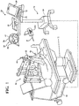
- the guidance station 20 is shown in an operating room of a medical facility.
- the guidance station 20 is set up to track movement of the various objects in the operating room.
- Such objects include, for example, a surgical instrument 22, a femur F, and a tibia T.
- the guidance station 20 tracks these objects for purposes of displaying their relative positions and orientations to the surgeon and, in some cases, for purposes of controlling or constraining movement of the surgical instrument 22 relative to a predefined path or anatomical boundary.
- the guidance station 20 also assists in arranging these objects and other objects in the operating room prior to the start of a surgical procedure and/or intra-operatively, as will be discussed further below.
- the guidance station 20 includes a computer cart assembly 24 that houses a navigation computer 26, or other type of control unit.
- a navigation interface is in operative communication with the navigation computer 26.
- the navigation interface includes a first display 28 adapted to be situated outside of the sterile field and a second display 29 adapted to be situated inside the sterile field.
- the displays 28, 29 are adjustably mounted to the computer cart assembly 24.
- First and second input devices 30, 32 such as a keyboard and mouse can be used to input information into the navigation computer 26 or otherwise select/control certain aspects of the navigation computer 26. Other input devices are contemplated including a touch screen (not shown) or voice-activation.
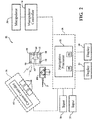
- a localizer 34 communicates with the navigation computer 26.
- the localizer 34 is an optical localizer and includes a camera unit 36 (also referred to as a sensing device).
- the camera unit 36 has an outer casing 38 that houses one or more optical position sensors 40.
- at least two optical sensors 40 are employed, preferably three or more.
- the optical sensors 40 may be three separate charge-coupled devices (CCD). In one embodiment three, one-dimensional CCDs are employed. It should be appreciated that in other embodiments, separate camera units, each with a separate CCD, or two or more CCDs, could also be arranged around the operating room.
- the CCDs detect infrared (IR) signals.
- Camera unit 36 is mounted on an adjustable arm to position the optical sensors 40 with a field of view of the below discussed trackers that, ideally, is free from obstructions.
- the adjustable arm allows adjustment of the camera unit 36 in at least one degree of freedom and, in some embodiments, in two or more degrees of freedom.
- the camera unit 36 includes a camera controller 42 in communication with the optical sensors 40 to receive signals from the optical sensors 40.
- the camera controller 42 communicates with the navigation computer 26 through either a wired or wireless connection (not shown).
- a wired or wireless connection may be an IEEE 1394 interface, which is a serial bus interface standard for high-speed communications and isochronous real-time data transfer.
- the connection could also use a company specific protocol.
- the optical sensors 40 communicate directly with the navigation computer 26.
- Position and orientation signals and/or data are transmitted to the navigation computer 26 for purposes of tracking the objects.
- the displays 28, 29 and camera unit 36 may be like those described in U.S. Patent No. 7,725,162 to Malackowski, et al. issued on May 25, 2010 , entitled “Surgery Systems”.
- the navigation computer 26 can be a personal computer or laptop computer.
- Navigation computer 26 has the displays 28, 29, central processing unit (CPU) and/or other processors, memory (not shown), and storage (not shown).
- the navigation computer 26 is loaded with software as described below.
- the software converts the signals/data received from the camera unit 36 into data representative of the position and orientation of the objects being tracked.
- Guidance station 20 communicates with a plurality of tracking devices 44, 46, 48, also referred to herein as trackers.
- one tracker 44 is firmly affixed to the femur F of the patient and another tracker 46 is firmly affixed to the tibia T of the patient.
- Trackers 44, 46 are firmly affixed to sections of bone. Trackers 44, 46 may be attached to the femur F and tibia T in the manner shown in U.S. Patent No. 7,725,162 . Trackers 44, 46 could also be mounted like those shown in U.S. Provisional Patent Application No.
- a tracker is attached to the patella (not shown) to track a position and orientation of the patella.
- the trackers 44, 46 could be mounted to other tissue types or parts of the anatomy.
- An instrument tracker 48 is rigidly attached to the surgical instrument 22.
- the instrument tracker 48 may be integrated into the surgical instrument 22 during manufacture or may be separately mounted to the surgical instrument 22 in preparation for the surgical procedure.
- the working end of the surgical instrument 22, which is being tracked by virtue of the instrument tracker 48, may be a rotating bur, electrical ablation device, or the like.
- the trackers 44, 46, 48 can be battery powered with an internal battery or may have leads to receive power through the navigation computer 26, which, like the camera unit 36, preferably receives external power.
- the surgical instrument 22 is an end effector of a machining station 56.
- a machining station 56 Such an arrangement is shown in U.S. Provisional Patent Application No. 61/679,258 , entitled, "Surgical Manipulator Capable of Controlling a Surgical Instrument in either a Semi-Autonomous Mode or a Manual, Boundary Constrained Mode.”
- a separate tracker (not shown) may be attached to a mobile cart 57 of the machining station 56 to track movement of the cart 57.
- joint position sensors such as position encoders, the guidance station 20 is able to determine a position of the cart 57 based on the position and orientation of the instrument tracker 48 and owing to the rigid connection of the instrument tracker 48 relative to the machining station 56.
- the optical sensors 40 of the localizer 34 receive light signals from the trackers 44, 46, 48.
- the trackers 44, 46, 48 are active trackers.
- each tracker 44, 46, 48 has at least three active tracking elements or markers for transmitting light signals to the optical sensors 40.
- the active markers can be, for example, light emitting diodes or LEDs 50 transmitting light, such as infrared light.
- the optical sensors 40 preferably have sampling rates of 100 Hz or more, more preferably 300 Hz or more, and most preferably 500 Hz or more. In some embodiments, the optical sensors 40 have sampling rates of 8000 Hz. The sampling rate is the rate at which the optical sensors 40 receive light signals from sequentially fired LEDs 50. In some embodiments, the light signals from the LEDs 50 are fired at different rates for each tracker 44, 46, 48.
- each of the LEDs 50 are connected to a tracker controller 62 located in a housing (not shown) of the associated tracker 44, 46, 48 that transmits/receives data to/from the navigation computer 26.
- the tracker controllers 62 transmit data on the order of several Megabytes/second through wired connections with the navigation computer 26. In other embodiments, a wireless connection may be used.
- the navigation computer 26 has a transceiver (not shown) to receive the data from the tracker controller 62.
- the trackers 44, 46, 48 may have passive markers (not shown), such as reflectors that reflect light emitted from the camera unit 36. The reflected light is then received by the optical sensors 40. Active and passive tracking elements are well known in the art.
- the navigation computer 26 includes a navigation processor 52.
- the camera unit 36 receives optical signals from the LEDs 50 of the trackers 44, 46, 48 and outputs to the processor 52 signals relating to the position of the LEDs 50 of the trackers 44, 46, 48 relative to the localizer 34. Based on the received optical signals, navigation processor 52 generates data indicating the relative positions and orientations of the trackers 44, 46, 48 relative to the localizer 34.
- the trackers 44, 46, 48 also include a gyroscope sensor 60 and accelerometer 70, such as the trackers shown in U.S. Provisional Patent Application No. 61/753,219, filed on January 16, 2013 , entitled, "Tracking Devices and Navigation Systems and Methods for Use Thereof".
- the navigation processor 52 could include one or more processors to control operation of the navigation computer 26.
- the processors can be any type of microprocessor or multi-processor system.
- the term processor is not intended to limit the scope of the invention to a single processor.
- navigation processor 52 determines the position and orientation of the surgical instrument 22 relative to the tissue (e.g., femur F and tibia T) against which the working end is to be applied.
- the previously loaded data includes data associated with pre-operative images, including MRI images, CT scans, etc. taken before the surgical procedure.
- the previously loaded data also includes geometric relationships between the working end of the surgical instrument 22 and the LEDs 50 on instrument tracker 48. Using well known navigation techniques for registration and coordinate system transformation, the patient's anatomy and the working end of the surgical instrument 22 can be registered into a coordinate reference frame of the localizer 34 so that the working end and the anatomy can be tracked together using the LEDs 50.
- navigation processor 52 forwards position and/or orientation data to a manipulator controller 54.
- the manipulator controller 54 can then use the data to control the machining station 56 as described in U.S. Provisional Patent Application No. 61/679,258 , entitled, "Surgical Manipulator Capable of Controlling a Surgical Instrument in either a Semi-Autonomous Mode or a Manual, Boundary Constrained Mode".
- the navigation processor 52 also generates image signals that indicate the relative position of the surgical instrument working end to the surgical site. These image signals are applied to the displays 28, 29. Displays 28, 29, based on these signals, generate images that allow the surgeon and surgical personnel to view the relative position of the surgical instrument working end to the surgical site.
- the displays, 28, 29, as discussed above, may include a touch screen or other input/output device that allows entry of commands.
- a localization engine 100 is a software module that can be considered part of the guidance station 20. Components of the localization engine 100 run on navigation processor 52. In some versions of the invention, the localization engine 100 may run on the manipulator controller 54.
- Localization engine 100 receives as inputs the optically-based signals from the camera controller 42 and, in some embodiments, the non-optically based signals from the tracker controller 62. Based on these signals, localization engine 100 determines the pose of the trackers 44, 46, 48 in the localizer coordinate system. The localization engine 100 forwards the signals representative of the poses of trackers 44, 46, 48 to a coordinate transformer 102.
- Coordinate transformer 102 is a navigation system software module that runs on navigation processor 52. Coordinate transformer 102 references the data that defines the relationship between the pre-operative images of the patient and the patient trackers 44, 46. Coordinate transformer 102 also stores the data indicating the pose of the working end of the surgical instrument relative to the instrument tracker 48.
- the coordinate transformer 102 then generates data indicating the position and orientation of the working end of the surgical instrument 22 relative to the tissue (e.g., bone) against which the instrument working end is applied. Image signals representative of these data are forwarded to displays 28, 29 enabling the surgeon and surgical personnel to view this information. To avoid interruption of this data, the line-of-sight between the trackers 44, 46, 48 and the sensors 40 is to be maintained. If there are obstructions to the line-of-sight, then errors may occur.
- the guidance station 20 is configured to assist with the pre-surgery and/or intra-operative placement of objects, such as the trackers 44, 46, 48, used in the operating room during a surgical procedure.
- the guidance station 20 provides instructions on the arrangement of the objects to facilitate procedural efficiency and to reduce possible obstructions to navigation during the surgical procedure.
- Other objects that may be arranged according to instructions from the guidance station 20 may include, but are not limited to, the patient, the machining station 56, surgical personnel, the camera unit 36, other instruments, equipment, or stations, and the like.
- the instructions provided by the guidance station 20 may be based on procedure information such as the type of procedure being performed, preferences of the surgeon performing the procedure, implant types/sizes, patient information, and other factors.
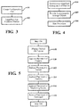
- the instructions from the guidance station 20 are provided based on the pre-operative plan.
- the pre-operative plan is created in step 101.
- Pre-operative plans are prescribed by surgeons for each patient and describe in detail the type of procedure being performed, the target anatomy that is being treated, the types, sizes, and/or shapes of implants (if any) that are being implanted, surgeon preferences, and other information.
- Creation of the pre-operative plan includes several steps. First, the patient is diagnosed to determine the appropriate treatment for the patient. Next, the surgeon prescribes the treatment. In the embodiment shown, the treatment is a total knee replacement.
- the surgeon's prescription includes the imaging of the patient's bones, i.e., the femur and tibia using MRI, CT scan, etc. Once imaging of the bones is complete, the images are used to prepare or select an appropriate design of a total knee implant. The design can also be based on a kinematic study of the patient performed in the operating room (OR) immediately prior to the surgery.
- the design includes the type of implant, the size/shape of the implant, and the location on the bones to which the implant is to be fixed (which includes identifying the tissue to be removed to receive the implant). This information may be stored in electronic form in a computer readable format such as a text file, image file, or the like.
- the design may be prepared or selected by the surgeon or by a third party. Once the design of the knee implant is determined, the surgeon reviews the design, and if acceptable, approves the design and the surgical procedure is scheduled. Once the surgical procedure is scheduled, the operating room is prepared for the surgery, which includes arranging the objects based on the pre-operative plan.
- the objects are arranged based on procedure information determined at the time of the surgery, i.e., not preoperatively.
- the pre-operative plan is stored on the guidance station 20 in step 103.
- the pre-operative plan may be stored in the navigation computer 26 using a wired or wireless internet connection to the navigation computer 26, by flash memory device, or the like.
- the surgeon or his or her designee transfers the encrypted pre-operative plan (including design information) to the guidance station 20, via hospital or surgical center secure local area network (Ethernet), secure USB flash drive, or secure wireless (WiFi) connection.
- the pre-operative plan is created using the guidance station 20.
- an OR Setup module 109 (see Figure 2 ) can be used to begin setting up the objects in the operating room.
- the OR Setup module 109 is a software module that runs on navigation computer 26.
- the surgical personnel can operate the OR Setup module 109 using the user interface and displays 28, 29 of the guidance station 20.
- the surgical personnel first load the procedure information (e.g., pre-operative plan) into the OR Setup module 109. When loaded, certain information is made available to the OR Setup module 109.
- the OR Setup module 109 determines a prescribed arrangement of objects based on the procedure information in step 104.
- the prescribed arrangement of objects can be determined by looking for certain information loaded into the OR Setup module 109 and matching the information to one of a plurality of prescribed arrangements listed in a look-up table.
- the look-up table is stored on the navigation computer 26. For instance, the information loaded may identify the type of procedure as "TOTAL KNEE - LEFT".
- the OR Setup module 109 is programmed to select a prescribed arrangement of objects based on this type of procedure by finding in the look-up table the specific arrangement associated with "TOTAL KNEE - LEFT".
- Prescribed arrangements include overhead layouts such as those shown in Figures 6 and 7 . These overhead layouts may be stored in the navigation computer 26 as image files or other file types. Alternatively, the overhead layouts may be part of the pre-operative plan and/or loaded along with the procedure information into the OR Setup module 109. Different layouts may be associated with different procedure types. Different layouts may also be associated with different surgeon preferences. For example, the layout shown in Figure 6 is for a right-handed surgeon, while the layout shown in Figure 7 is for a left-handed surgeon.
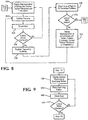
- the guidance station 20 provides instructions to arrange the objects accordingly in step 105. Such instructions can be carried out in the order shown in Figure 5 . Other orders of these instructions are also contemplated.
- the guidance station 20 displays the overhead layout determined by the OR Setup module.
- the overhead layout is shown on the displays 28, 29.
- the overhead layout provides the surgical personnel with instructions on the gross placement of the objects including the guidance station 20, the patient and operating table, the machining station 56, the surgeon, nurses, and other objects. As described further below, more precise positioning of trackers 44, 46 and the machining station 56 is also navigationally guided by the guidance station 20.
- step 110 which directs placement of the camera unit 36. Transition to step 110 may require input from the surgical personnel, such as selecting "OK” or "DONE" on the displays 28, 29 with an input device to indicate to the OR Setup module 109 that the guidance station 20 is in position.
- the camera unit 36 is adjustable about at least one degree of freedom and, in some cases, about two or more degrees of freedom.
- the guidance station 20, through the OR Setup module 109 instructs the surgical personnel on how to position the camera unit 36.
- This instruction may include written instructions present on displays 28, 29 to adjust the camera unit 36 to a predetermined height or a predetermine angle relative to ground.
- the instruction for placement of the camera unit 36 may include visual guidance showing an exemplary setup for the camera unit 36. Once the camera unit 36 is properly placed, transition to step 112 may require input from the surgical personnel, such as selecting "OK" or "DONE" on the displays 28, 29 with an input device to indicate to the OR Setup module 109 that the camera unit 36 is in position.
- joints of the arms for moving the camera unit 36 may have position encoders that can be read by the navigation computer 26 and used to dynamically track movement of the camera unit 36 relative to the ground based on known geometric relationships between the cart assembly 24, ground, adjustment arms, and camera unit 36.
- visual guidance on the displays 28, 29 can include showing a representation of the current position of the camera unit 36 (shown in hidden lines) relative to a representation of the desired position of the camera unit 36. The representation of the current position dynamically moves on the displays 28, 29 toward or away from the representation of the desired position as the user adjusts a position of the camera unit 36.
- the OR Setup module 109 can transmit images to the displays 28, 29 showing the direction of required movement to reach the desired position, such as the arrow shown in Figure 5B . Once the current position of the camera unit 36 is within a predefined tolerance of the desired position, the OR Setup module 109 indicates that the desired position has been reached and moves to Step 112.
- the patient is brought into the operating room on the operating table in step 112.
- the patient in the case of a total knee replacement, is either brought in under anesthesia or anesthesia is administered in the operating room.
- the surgical staff may also secure the leg of interest in a leg holder, and drape the patient and equipment.
- One such leg holder is shown in U.S. Patent Application No. 13/554,010 , entitled, "Multi-position Limb Holder", published as U.S. Patent Application Publication No. 2013/0019883 .
- Instructions on the placement of the patient may include written instructions on the displays 28, 29 regarding positioning of the operating table relative to the guidance station 20. Such instructions may include establishing a desired distance between the computer cart assembly 24 and the operating table or aligning a particular side of the operating table with respect to the camera unit 36.
- the instruction for placement of the patient may include visual guidance showing an exemplary setup for the patient relative to the camera unit 36.
- a video camera (not shown) is attached to the camera unit 36.
- the video camera is oriented such that a field of view of the camera unit 36 can be associated with the field of view of the video camera.
- the two fields of view may be matched or otherwise correlated such that if an object (e.g., LEDs 50) can be seen in video images streamed from the video camera, the objects are also within the field of view of the camera unit 36.
- Video images from the video camera can be streamed to the displays 28, 29 during any of the steps in Figure 5 .
- step 112 while the displays 28, 29 show a window 113 with video images streaming from the video camera in the window 113, the instructions provided on the displays 28, 29 may also include written instructions stating to the surgical personnel to place the patient within the window 113.
- the window 113 may also show where certain edges or sides of the operating table are to be located by overlaying geometric visual aids (such as cross-hairs, edge lines, etc.) onto the video images and providing accompanying written instructions.
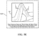
- Tracker placement is performed in step 114.
- One exemplary embodiment of instructions provided by the guidance station 20 for placing the trackers 44, 46 is shown in Figure 8 .
- representations of the femur F and tibia T are shown on the displays 28, 29 with desired tracker placement and associated instructions.
- An example of this is shown in Figure 5D .
- Generic bone representations are used to generally show proper placement based on distance from the knee joint, for example, or distances from certain anatomical landmarks associated with the knee joint (e.g, distances from patella, tibial tubercle, etc.).
- Written instructions on the displays 28, 29 can indicate distances from the anatomical landmarks to each of the trackers 44, 46 (distances may be indicated from landmark to the base of each tracker 44, 46 mounted to bone). A desired distance between trackers 44, 46 (or the bases thereof) may also be numerically and visually depicted on the displays 28, 29.
- the instructions on the display 28, 29 include written instructions on the placement of the leg in a leg holder prior to placing the trackers 44, 46 and instructions on securing the leg holder in position.
- One such leg holder is shown in U.S. Patent Application No. 13/554,010 , entitled, "Multi-position Limb Holder", published as U.S. Patent Application Publication No. 20 13/0019883 .
- the video camera described above may be integrated into a machine vision system of the guidance station 20 with ability to identify the leg of the patient using conventional machine vision technology.
- the guidance station 20 overlays desired positions of the trackers 44, 46 on the displays 28, 29 (shown by arrows), while simultaneously and continuously showing the video images from the video camera, which shows the surgeon and/or surgical personnel placing the trackers 44, 46 (actual trackers not shown in Figure 5E ).
- the camera unit 36 is activated to begin receiving position-related signals from the LEDs 50, of the trackers 44, 46.
- step 124 the navigation computer 26 measures distances between the LEDs 50 on tracker 44 with the LEDs 50 on tracker 46. This provides a basic indication of how far apart the trackers 44, 46 are located on the bones, e.g., femur and tibia. In one embodiment, a shortest distance between the closest two LEDs 50 and a farthest distance between the farthest two LEDs 50 are measured. In step 126 these measure distances are compared to a predetermined range of distances. If both of the shortest and farthest measured distances fall within the range, the method proceeds to step 128. If not, the method goes back to step 120 and the trackers 44, 46 are repositioned according to the instructions in step 120.
- the instructions can additionally include details on whether the trackers 44, 46 were too close together or too far apart - giving the surgical personnel additional guidance on where to position the trackers 44, 46.
- Repositioning of the trackers 44, 46 may simply require adjustment of the trackers 44, 46 about one or more adjustable degrees of freedom without requiring removal of the base (or bone pins) from the bone. In extreme cases, the trackers 44, 46 will need to be completely removed from the bone and re-mounted.
- the trackers 44, 46 are registered to the anatomy. Registration of bone surfaces and reference landmarks is well-known in the art using pointers P and will not be described in detail. Registration results in the pre-operative MRI or CT images being associated with positions of the LEDs 50 on the trackers 44, 46. As a result, movement of the femur F and tibia T can be tracked by tracking movement of the LEDs 50.
- the navigation computer 26 can simulate movement of the femur F and tibia T through a range of motion from flexion to extension and in all anticipated positions of the femur and tibia during the surgical procedure. For instance, the procedure may require the knee to be placed in maximum flexion and extension.
- the navigation processor 52 can simulate where the LEDs 50 will be located at maximum flexion and extension positions of the leg and determine whether the LEDs 50 will be within the field-of-view of each of the sensors 40 in all of these positions since the field-of-view of the sensors 40 is also known to the navigation computer 26. In other words, the navigation computer 26 can simulate movement of the femur F and tibia T during the procedure and detect whether any of the LEDs 50 will be blocked from the field-of-view of any of the sensors 40.
- the instructions on the displays 28, 29 may require the surgical personnel to actually move the leg through maximum extension and flexion in the leg holder, while the guidance station 20 tracks the LEDs 50 on the trackers 44, 46. Blockage is then identified by determining if at any position of the leg, any of the LEDs 50 is blocked from transmitting signals to the sensors 40.
- step 134 representations of the actual bones of the patient are shown on the displays 28, 29 along with the current tracker placement and the desired tracker placement (similar to Figure 5E , but now using navigation position information). Instructions for moving or repositioning the trackers 44, 46 are also displayed on displays 28, 29. In some cases, repositioning may simply require sliding, tilting or rotating a head of one of the trackers 44, 46 using adjustment features of the trackers 44, 46, without requiring complete removal of the trackers 44, 46 from the bone. See, for example, adjustment features of the trackers shown in U.S. Provisional Patent Application No. 61/753,219, filed on January 16, 2013 , entitled, "Tracking Devices and Navigation Systems and Methods for Use Thereof". In other cases, one or both of the trackers 44, 46 need to be removed from the bones.
- step 124 the initial error check in step 124 is performed again. If the error is acceptable, then the trackers 44, 46 are re-registered to the anatomy and the remaining steps continue as before.
- step 132 if no blockage is predicted or detected, the method proceeds to step 116. Transition to step 116 may be automatic after the simulations or movements are performed in step 132, or transition to step 116 may require input from the surgical personnel, such as selecting "OK" or "DONE" on the displays 28, 29 with an input device to indicate to the OR Setup module 109 that the patient is in position.
- the trackers 44, 46 may be setup according to the procedure outlined in U.S. Provisional Patent Application No. 61/753,219, filed on January 16, 2013 , entitled, "Tracking Devices and Navigation Systems and Methods for Use Thereof", which may improve the likelihood that the trackers 44, 46 do not require repositioning during positioning in step 114.
- the surgeon also has the ability to again review the design, confirm it matches the patient, and either give final approval or makes revisions in implant size, position, and/or orientation.
- Step 116 Instructions for placement of the machining station 56 are provided in step 116.
- steps 136 through 142 in Figure 9 One example of how these instructions are provided is shown in steps 136 through 142 in Figure 9 .
- the guidance station 20 can assist in guiding the machining station 56 into position relative to the bones to be machined.
- step 136 the desired placement of the machining station 56 is shown on displays 28, 29.
- the cart 57 of the machining station 56 also has an integrated display 59 which is in communication with the guidance station 20 (see Figure 1 ).
- the machining station display 59 additionally shows the desired placement of the machining station 56.
- the desired placement may be an overhead visual illustration of the cart 57 in a desired position, such as shown in Figures 6 and 7 .
- a position and orientation of the cart 57 is tracked by the guidance station 20 using the instrument tracker 48. More specifically, owing to rigid connections of the instrument tracker 48 to the end effector and the end effector to an arm/coupler structure of the machining station 56, the guidance station 20 is able to determine a position and orientation of the cart 57 based on the position and orientation of the instrument tracker 48 using: (1) joint angle data measured by position encoders located at joints in the machining station 56 and/or joint angle data calculated by a kinematics module, as described in U.S. Provisional Patent Application No.
- 61/679,258 entitled, "Surgical Manipulator Capable of Controlling a Surgical Instrument in either a Semi-Autonomous Mode or a Manual, Boundary Constrained Mode” and (2) data relating to the arm/coupler structure (e.g., virtual model data) of the machining station 56, as described in U.S. Provisional Patent Application No. 61/679,258 , entitled, "Surgical Manipulator Capable of Controlling a Surgical Instrument in either a Semi-Autonomous Mode or a Manual, Boundary Constrained Mode".
- a separate tracker (not shown) is attached to and calibrated to a virtual model of the cart 57 to track a position and orientation of the cart 57.
- the displays 28, 29, 59 in some embodiments not only show the desired overhead position of the cart 57, but also the current position of the cart 57.
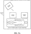
- One example of representations of the cart 57 shown on displays 28, 29, 59 is shown Figure 9A .
- one visual representation is an image of the cart 57 (represented by a 2-D rectangle) shown in the desired position.
- Another visual representation is an image of the cart 57 (represented by a 2-D rectangle) shown in the current position.
- the representation of the cart 57 in the current position moves on the displays 28, 29, 59 as the cart 57 is moved.
- Further instructions provided by the guidance station 20 may include geometric images, such as an arrow, guiding the surgical personnel as to the direction in which to move the cart 57 to reach the desired position.
- step 138 the surgical personnel place the machining station 56 in the desired position by watching the displays 28, 29, 59, and moving the cart 57 such that the visual representations on the displays 28, 29, 59 of the actual cart position moves toward the visual representation of the desired position.
- step 140 the OR Setup module 109 checks the error between actual position and desired position until the cart 57 reaches the desired position. Once the actual position of the machining station 56 is within a predetermined tolerance of the desired position, as depicted by the visual representation of the actual position of the cart 57 being aligned with the visual representation of the desired position of the cart 57, i.e., the rectangles are aligned, the OR Setup module 109 indicates that the machining station 56 is in the desired position and moves to step 118.
- the visual images on the displays 28, 29, 59 may blink or provide some other visual effect when the cart 57 has reached the desired position.
- step 118 the guidance station 20 instructs the surgical personnel on their proper positions relative to the patient, machining station 56, guidance station 20, etc. This may be done by re-displaying the overhead layout, such as those shown in Figures 6 and 7 . Once the surgical personnel are in position and ready, the procedure can be started - see step 106 in Figure 4 .
- the machining station 56 is a robotic surgical cutting system for cutting away material from a patient's anatomy, such as bone or soft tissue.
- the cutting system cuts away material to be replaced by surgical implants such as hip and knee implants, including unicompartmental, bicompartmental, or total knee implants.
- surgical implants such as hip and knee implants, including unicompartmental, bicompartmental, or total knee implants.
- the instrument 22 has a cutting tool that is movable in three degrees of freedom relative to a handheld housing and is manually positioned by the hand of the surgeon, without the aid of cutting jigs, guide arms or other constraining mechanism.
- a cutting tool that is movable in three degrees of freedom relative to a handheld housing and is manually positioned by the hand of the surgeon, without the aid of cutting jigs, guide arms or other constraining mechanism.
- Such systems are shown in U.S. Patent Application No. 13/600,888 , entitled, "Surgical Instrument Including Housing, a Cutting Accessory that Extends from the Housing and Actuators that Establish the Position of the Cutting Accessory Relative to the Housing".
- the system includes a hand held surgical cutting instrument having a cutting tool.
- a control system controls movement of the cutting tool in at least 3 degrees of freedom using internal actuators/motors, as shown in U.S. Patent Application No. 13/600,888 , entitled, "Surgical Instrument Including Housing, a Cutting Accessory that Extends from the Housing and Actuators that Establish the Position of the Cutting Accessory Relative to the Housing".
- the guidance station 20 communicates with the control system.
- One tracker (such as tracker 48) is mounted to the instrument.
- Other trackers (such as trackers 44, 46) are mounted to a patient's anatomy.
- the guidance station 20 communicates with the control system of the hand held surgical cutting instrument.
- the guidance station 20 communicates position and/or orientation data to the control system.
- the position and/or orientation data is indicative of a position and/or orientation of the instrument 22 relative to the anatomy.
- This communication provides closed loop control to control cutting of the anatomy such that the cutting occurs within a predefined boundary (the term predefined boundary is understood to include predefined trajectory, volume, line, other shapes or geometric forms, and the like).
- the trackers 44, 46, 48 could be other line-of-sight tracking devices or non line-of-sight tracking devices used for navigation.
- the trackers 44, 46, 48 could employ sound waves, magnetic fields, RF signals, and the like to determine position and/or orientation.
- step 110 relates to placement of sensing devices, transmitters, generators, etc. associated with these other types of navigation systems.
- steps 130 and 132 relate to checking for obstructions or other interference with signals from these other types of navigation systems. In essence, surgical personnel are instructed to place trackers of the navigation system with respect to the patient's anatomy, regardless of the type of navigation employed, so that obstructions or interference is minimized or within acceptable tolerances.
- the objects may be arranged with respect to an operating room table that is fixed in the operating room, i.e., unable to be readily moved, except for adjustments of portions of the operating room table.
- some or all of the objects to be arranged according to their desired placement may be located outside the operating room and first need to be moved into the operating room. In other embodiments, some or all of the objects to be arranged according to their desired placement may already be located inside the operating room, but not yet in their desired placements.
- pre-surgery is considered the time leading up to any cutting or incision of the patient in the operating room for purposes of treatment.
- Such cutting may include the cutting of skin and tissue to access the knee joint for purposes of knee replacement or the hip joint for purposes of hip replacement.
- arranging the objects in the operating room may be performed manually such as by pushing a wheeled cart of the object into position, or manually attaching trackers to the patient.
- arranging the objects may include guiding the objects into their desired placement remotely or by some automated control, such as by moving an automated cart using associated steering controls.
Applications Claiming Priority (3)
| Application Number | Priority Date | Filing Date | Title |
|---|---|---|---|
| US201361779725P | 2013-03-13 | 2013-03-13 | |
| PCT/US2014/023154 WO2014159350A1 (en) | 2013-03-13 | 2014-03-11 | System for arranging objects in an operating room in preparation for surgical procedures |
| EP14714524.7A EP2996615B1 (en) | 2013-03-13 | 2014-03-11 | System for arranging objects in an operating room in preparation for surgical procedures |
Related Parent Applications (2)
| Application Number | Title | Priority Date | Filing Date |
|---|---|---|---|
| EP14714524.7A Division EP2996615B1 (en) | 2013-03-13 | 2014-03-11 | System for arranging objects in an operating room in preparation for surgical procedures |
| EP14714524.7A Division-Into EP2996615B1 (en) | 2013-03-13 | 2014-03-11 | System for arranging objects in an operating room in preparation for surgical procedures |
Publications (2)
| Publication Number | Publication Date |
|---|---|
| EP3459468A1 EP3459468A1 (en) | 2019-03-27 |
| EP3459468B1 true EP3459468B1 (en) | 2020-07-15 |
Family
ID=50397326
Family Applications (2)
| Application Number | Title | Priority Date | Filing Date |
|---|---|---|---|
| EP14714524.7A Active EP2996615B1 (en) | 2013-03-13 | 2014-03-11 | System for arranging objects in an operating room in preparation for surgical procedures |
| EP18204774.6A Active EP3459468B1 (en) | 2013-03-13 | 2014-03-11 | Method and system for arranging objects in an operating room |
Family Applications Before (1)
| Application Number | Title | Priority Date | Filing Date |
|---|---|---|---|
| EP14714524.7A Active EP2996615B1 (en) | 2013-03-13 | 2014-03-11 | System for arranging objects in an operating room in preparation for surgical procedures |
Country Status (8)
| Country | Link |
|---|---|
| US (4) | US9652591B2 (zh) |
| EP (2) | EP2996615B1 (zh) |
| JP (2) | JP6442472B2 (zh) |
| KR (2) | KR102274277B1 (zh) |
| CN (2) | CN108175503B (zh) |
| AU (2) | AU2014240998B2 (zh) |
| CA (1) | CA2897861A1 (zh) |
| WO (1) | WO2014159350A1 (zh) |
Families Citing this family (56)
| Publication number | Priority date | Publication date | Assignee | Title |
|---|---|---|---|---|
| US7708741B1 (en) * | 2001-08-28 | 2010-05-04 | Marctec, Llc | Method of preparing bones for knee replacement surgery |
| US9707043B2 (en) | 2011-09-02 | 2017-07-18 | Stryker Corporation | Surgical instrument including housing, a cutting accessory that extends from the housing and actuators that establish the position of the cutting accessory relative to the housing |
| US9585597B2 (en) * | 2012-07-24 | 2017-03-07 | Zimmer, Inc. | Patient specific instrumentation with MEMS in surgery |
| WO2014159350A1 (en) | 2013-03-13 | 2014-10-02 | Stryker Corporation | System for arranging objects in an operating room in preparation for surgical procedures |
| US10500004B2 (en) * | 2014-03-17 | 2019-12-10 | Intuitive Surgical Operations, Inc. | Guided setup for teleoperated medical device |
| KR102450087B1 (ko) | 2014-03-17 | 2022-10-06 | 인튜어티브 서지컬 오퍼레이션즈 인코포레이티드 | 원격 조종 의료 시스템에서 미리 설정된 암 위치를 가지는 자동화된 구조 |
| US20160179315A1 (en) * | 2014-12-18 | 2016-06-23 | Aditazz, Inc. | Room plan generation user interface for component placement configuration |
| US10025473B2 (en) | 2014-12-18 | 2018-07-17 | Aditazz, Inc. | Room plan generation user interface for room plan selection |
| US10226302B2 (en) * | 2015-05-15 | 2019-03-12 | Mako Surgical Corporation | Systems and methods for providing guidance for a robotic medical procedure |
| JP7166760B2 (ja) * | 2015-06-09 | 2022-11-08 | インテュイティブ サージカル オペレーションズ, インコーポレイテッド | 外科的処置アトラスを用いた手術システムの構成 |
| US20170061039A1 (en) * | 2015-08-24 | 2017-03-02 | Aditazz, Inc. | Computer-implemented system and method for placing objects in a room |
| DE102016116702B4 (de) * | 2015-09-14 | 2019-01-24 | Fanuc Corporation | Messsystem zum Kalibrieren der mechanischen Parameter eines Roboters |
| KR20180068336A (ko) | 2015-11-12 | 2018-06-21 | 인튜어티브 서지컬 오퍼레이션즈 인코포레이티드 | 훈련 또는 보조 기능들을 갖는 수술 시스템 |
| CN108778179A (zh) | 2016-02-26 | 2018-11-09 | 思想外科有限公司 | 用于指导用户定位机器人的方法和系统 |
| WO2017214696A1 (en) * | 2016-06-13 | 2017-12-21 | Synaptive Medical (Barbados) Inc. | Virtual operating room layout planning and analysis tool |
| US20190183589A1 (en) * | 2016-08-23 | 2019-06-20 | Neurosimplicity, Llc | System, devices and method for surgical navigation including active tracking and drift elimination |
| US11314846B1 (en) * | 2016-09-29 | 2022-04-26 | OR Link, Inc. | Surgical communication and computerization infrastructure |
| AU2017340607B2 (en) | 2016-10-05 | 2022-10-27 | Nuvasive, Inc. | Surgical navigation system and related methods |
| WO2018132835A1 (en) * | 2017-01-16 | 2018-07-19 | Smith & Nephew, Inc. | Tracked surgical tool with controlled extension |
| CN110603002A (zh) | 2017-03-10 | 2019-12-20 | 拜欧米特制造有限责任公司 | 增强现实支持的膝盖手术 |
| US10610307B2 (en) * | 2017-09-28 | 2020-04-07 | General Electric Company | Workflow assistant for image guided procedures |
| US20190102533A1 (en) | 2017-10-04 | 2019-04-04 | Stryker Corporation | Peripheral Cyber-Security Device |
| JP7155511B2 (ja) * | 2017-11-17 | 2022-10-19 | ソニーグループ株式会社 | 手術システム、情報処理装置、及び情報処理方法 |
| US11809823B2 (en) | 2017-12-07 | 2023-11-07 | International Business Machines Corporation | Dynamic operating room scheduler using machine learning |
| US11484379B2 (en) * | 2017-12-28 | 2022-11-01 | Orbsurgical Ltd. | Microsurgery-specific haptic hand controller |
| US11114199B2 (en) | 2018-01-25 | 2021-09-07 | Mako Surgical Corp. | Workflow systems and methods for enhancing collaboration between participants in a surgical procedure |
| EP3764932A4 (en) * | 2018-03-13 | 2021-05-26 | Intuitive Surgical Operations, Inc. | MANUAL MOVEMENT GUIDANCE PROCESSES OF MEDICAL SYSTEMS |
| EP3545896A1 (en) * | 2018-03-30 | 2019-10-02 | Koninklijke Philips N.V. | Monitoring of moving objects in an operation room |
| WO2019222728A1 (en) * | 2018-05-18 | 2019-11-21 | Smith & Nephew Inc. | System and method for tracking resection planes |
| US11007031B2 (en) * | 2018-08-14 | 2021-05-18 | Verb Surgical Inc. | Setup of surgical robots using an augmented mirror display |
| US11612438B2 (en) * | 2018-09-05 | 2023-03-28 | Point Robotics Medtech Inc. | Navigation system and method for medical operation by a robotic system using a tool |
| US10858023B2 (en) | 2019-03-15 | 2020-12-08 | Medline Industries, Inc. | Mattress air supply device cart and methods of use |
| USD914217S1 (en) | 2019-03-15 | 2021-03-23 | Medline Industries, Inc. | Cart |
| US11690680B2 (en) * | 2019-03-19 | 2023-07-04 | Mako Surgical Corp. | Trackable protective packaging for tools and methods for calibrating tool installation using the same |
| EP4003205A1 (en) * | 2019-07-25 | 2022-06-01 | Howmedica Osteonics Corp. | Positioning a camera for perspective sharing of a surgical site |
| US11548140B2 (en) * | 2019-08-15 | 2023-01-10 | Covidien Lp | System and method for radio based location of modular arm carts in a surgical robotic system |
| KR102274167B1 (ko) * | 2019-09-05 | 2021-07-12 | 큐렉소 주식회사 | 로봇의 위치 가이드 장치, 이의 방법 및 이를 포함하는 시스템 |
| US11612440B2 (en) | 2019-09-05 | 2023-03-28 | Nuvasive, Inc. | Surgical instrument tracking devices and related methods |
| JP2022550148A (ja) * | 2019-09-26 | 2022-11-30 | ストライカー・ユーロピアン・オペレーションズ・リミテッド | 手術器具用トラッカ |
| EP3808304A1 (en) * | 2019-10-16 | 2021-04-21 | DePuy Ireland Unlimited Company | Method and system for guiding position and orientation of a robotic device holding a surgical tool |
| CN112420143A (zh) * | 2019-11-27 | 2021-02-26 | 上海联影智能医疗科技有限公司 | 提供个性化健康护理的系统,方法和装置 |
| CN112489745A (zh) * | 2019-11-27 | 2021-03-12 | 上海联影智能医疗科技有限公司 | 用于医疗设施的感测装置及实施方法 |
| US11430564B2 (en) | 2019-11-27 | 2022-08-30 | Shanghai United Imaging Intelligence Co., Ltd. | Personalized patient positioning, verification and treatment |
| US20220000558A1 (en) * | 2020-07-05 | 2022-01-06 | Asensus Surgical Us, Inc. | Augmented reality surgery set-up for robotic surgical procedures |
| CN112155733B (zh) * | 2020-09-29 | 2022-01-28 | 苏州微创畅行机器人有限公司 | 可读存储介质、骨建模配准系统及骨科手术系统 |
| CN112641510B (zh) * | 2020-12-18 | 2021-08-17 | 北京长木谷医疗科技有限公司 | 关节置换手术机器人导航定位系统及方法 |
| JP2024513204A (ja) | 2021-03-31 | 2024-03-22 | ムーン サージカル エスアエス | 腹腔鏡下外科手術を実施するための外科手術用器具と併用するための協調操作式外科手術用システム |
| US11812938B2 (en) | 2021-03-31 | 2023-11-14 | Moon Surgical Sas | Co-manipulation surgical system having a coupling mechanism removeably attachable to surgical instruments |
| US11844583B2 (en) | 2021-03-31 | 2023-12-19 | Moon Surgical Sas | Co-manipulation surgical system having an instrument centering mode for automatic scope movements |
| US11819302B2 (en) | 2021-03-31 | 2023-11-21 | Moon Surgical Sas | Co-manipulation surgical system having user guided stage control |
| US11832909B2 (en) | 2021-03-31 | 2023-12-05 | Moon Surgical Sas | Co-manipulation surgical system having actuatable setup joints |
| US20220384025A1 (en) * | 2021-05-28 | 2022-12-01 | Cilag Gmbh International | Control access verification of a health care professional |
| WO2023089100A1 (en) * | 2021-11-18 | 2023-05-25 | Advanced Osteotomy Tools - Aot Ag | Method of positioning a cutting device involved in a surgical cutting process performed in an operation space |
| EP4241716A1 (en) | 2022-03-08 | 2023-09-13 | Stryker European Operations Limited | Technique for determining a patient-specific marker arrangement for a tracker of a surgical tracking system |
| CN115789443B (zh) * | 2022-11-21 | 2023-11-14 | 深圳市安立信电子有限公司 | 一种伽玛自动校准调试的医疗显示器 |
| US11839442B1 (en) | 2023-01-09 | 2023-12-12 | Moon Surgical Sas | Co-manipulation surgical system for use with surgical instruments for performing laparoscopic surgery while estimating hold force |
Family Cites Families (187)
| Publication number | Priority date | Publication date | Assignee | Title |
|---|---|---|---|---|
| GB2082346B (en) | 1980-07-04 | 1984-05-16 | Komatsu Mfg Co Ltd | Method and device for automatically retreating and returning a tool in a machine tool |
| US5078140A (en) | 1986-05-08 | 1992-01-07 | Kwoh Yik S | Imaging device - aided robotic stereotaxis system |
| US5251127A (en) | 1988-02-01 | 1993-10-05 | Faro Medical Technologies Inc. | Computer-aided surgery apparatus |
| US4979949A (en) | 1988-04-26 | 1990-12-25 | The Board Of Regents Of The University Of Washington | Robot-aided system for surgery |
| IL89484A (en) | 1989-03-03 | 1992-08-18 | Nct Ltd Numerical Control Tech | System for automatic finishing of machined parts |
| US5343391A (en) | 1990-04-10 | 1994-08-30 | Mushabac David R | Device for obtaining three dimensional contour data and for operating on a patient and related method |
| US5562448A (en) | 1990-04-10 | 1996-10-08 | Mushabac; David R. | Method for facilitating dental diagnosis and treatment |
| US5569578A (en) | 1990-04-10 | 1996-10-29 | Mushabac; David R. | Method and apparatus for effecting change in shape of pre-existing object |
| US5086401A (en) * | 1990-05-11 | 1992-02-04 | International Business Machines Corporation | Image-directed robotic system for precise robotic surgery including redundant consistency checking |
| US6347240B1 (en) | 1990-10-19 | 2002-02-12 | St. Louis University | System and method for use in displaying images of a body part |
| US5662111A (en) | 1991-01-28 | 1997-09-02 | Cosman; Eric R. | Process of stereotactic optical navigation |
| US5279309A (en) | 1991-06-13 | 1994-01-18 | International Business Machines Corporation | Signaling device and method for monitoring positions in a surgical operation |
| US6963792B1 (en) | 1992-01-21 | 2005-11-08 | Sri International | Surgical method |
| US6788999B2 (en) | 1992-01-21 | 2004-09-07 | Sri International, Inc. | Surgical system |
| US5603318A (en) | 1992-04-21 | 1997-02-18 | University Of Utah Research Foundation | Apparatus and method for photogrammetric surgical localization |
| FR2691093B1 (fr) | 1992-05-12 | 1996-06-14 | Univ Joseph Fourier | Robot de guidage de gestes et procede de commande. |
| US5524180A (en) | 1992-08-10 | 1996-06-04 | Computer Motion, Inc. | Automated endoscope system for optimal positioning |
| US5397323A (en) | 1992-10-30 | 1995-03-14 | International Business Machines Corporation | Remote center-of-motion robot for surgery |
| US5517990A (en) | 1992-11-30 | 1996-05-21 | The Cleveland Clinic Foundation | Stereotaxy wand and tool guide |
| GB9405299D0 (en) | 1994-03-17 | 1994-04-27 | Roke Manor Research | Improvements in or relating to video-based systems for computer assisted surgery and localisation |
| US5623582A (en) | 1994-07-14 | 1997-04-22 | Immersion Human Interface Corporation | Computer interface or control input device for laparoscopic surgical instrument and other elongated mechanical objects |
| ATE252349T1 (de) | 1994-09-15 | 2003-11-15 | Visualization Technology Inc | System zur positionserfassung mittels einer an einem patientenkopf angebrachten referenzeinheit zur anwendung im medizinischen gebiet |
| US6646541B1 (en) | 1996-06-24 | 2003-11-11 | Computer Motion, Inc. | General purpose distributed operating room control system |
| US5891157A (en) | 1994-09-30 | 1999-04-06 | Ohio Medical Instrument Company, Inc. | Apparatus for surgical stereotactic procedures |
| US5695501A (en) | 1994-09-30 | 1997-12-09 | Ohio Medical Instrument Company, Inc. | Apparatus for neurosurgical stereotactic procedures |
| US6978166B2 (en) | 1994-10-07 | 2005-12-20 | Saint Louis University | System for use in displaying images of a body part |
| DE29521895U1 (de) | 1994-10-07 | 1998-09-10 | Univ St Louis | Chirurgisches Navigationssystem umfassend Referenz- und Lokalisationsrahmen |
| US5882206A (en) | 1995-03-29 | 1999-03-16 | Gillio; Robert G. | Virtual surgery system |
| US5730129A (en) | 1995-04-03 | 1998-03-24 | General Electric Company | Imaging of interventional devices in a non-stationary subject |
| US5649956A (en) | 1995-06-07 | 1997-07-22 | Sri International | System and method for releasably holding a surgical instrument |
| US5814038A (en) | 1995-06-07 | 1998-09-29 | Sri International | Surgical manipulator for a telerobotic system |
| WO1997000649A1 (en) | 1995-06-20 | 1997-01-09 | Wan Sing Ng | Articulated arm for medical procedures |
| JPH0970780A (ja) | 1995-09-06 | 1997-03-18 | Fanuc Ltd | ロボットのツール形状補正方式 |
| US5784542A (en) | 1995-09-07 | 1998-07-21 | California Institute Of Technology | Decoupled six degree-of-freedom teleoperated robot system |
| US5806518A (en) | 1995-09-11 | 1998-09-15 | Integrated Surgical Systems | Method and system for positioning surgical robot |
| US6351659B1 (en) | 1995-09-28 | 2002-02-26 | Brainlab Med. Computersysteme Gmbh | Neuro-navigation system |
| US5682886A (en) | 1995-12-26 | 1997-11-04 | Musculographics Inc | Computer-assisted surgical system |
| US5971976A (en) | 1996-02-20 | 1999-10-26 | Computer Motion, Inc. | Motion minimization and compensation system for use in surgical procedures |
| US6063095A (en) | 1996-02-20 | 2000-05-16 | Computer Motion, Inc. | Method and apparatus for performing minimally invasive surgical procedures |
| US5855583A (en) | 1996-02-20 | 1999-01-05 | Computer Motion, Inc. | Method and apparatus for performing minimally invasive cardiac procedures |
| US6436107B1 (en) | 1996-02-20 | 2002-08-20 | Computer Motion, Inc. | Method and apparatus for performing minimally invasive surgical procedures |
| US6699177B1 (en) | 1996-02-20 | 2004-03-02 | Computer Motion, Inc. | Method and apparatus for performing minimally invasive surgical procedures |
| US5769092A (en) | 1996-02-22 | 1998-06-23 | Integrated Surgical Systems, Inc. | Computer-aided system for revision total hip replacement surgery |
| US5952796A (en) | 1996-02-23 | 1999-09-14 | Colgate; James E. | Cobots |
| US5884682A (en) | 1996-03-21 | 1999-03-23 | Cae Newnes Ltd. | Position-based integrated motion controlled curve sawing |
| US5792135A (en) | 1996-05-20 | 1998-08-11 | Intuitive Surgical, Inc. | Articulated surgical instrument for performing minimally invasive surgery with enhanced dexterity and sensitivity |
| US5807377A (en) | 1996-05-20 | 1998-09-15 | Intuitive Surgical, Inc. | Force-reflecting surgical instrument and positioning mechanism for performing minimally invasive surgery with enhanced dexterity and sensitivity |
| US6017354A (en) | 1996-08-15 | 2000-01-25 | Stryker Corporation | Integrated system for powered surgical tools |
| US6024576A (en) | 1996-09-06 | 2000-02-15 | Immersion Corporation | Hemispherical, high bandwidth mechanical interface for computer systems |
| US6331116B1 (en) | 1996-09-16 | 2001-12-18 | The Research Foundation Of State University Of New York | System and method for performing a three-dimensional virtual segmentation and examination |
| US5824085A (en) | 1996-09-30 | 1998-10-20 | Integrated Surgical Systems, Inc. | System and method for cavity generation for surgical planning and initial placement of a bone prosthesis |
| US5776136A (en) | 1996-09-30 | 1998-07-07 | Integrated Surgical Systems, Inc. | Method and system for finish cutting bone cavities |
| US7302288B1 (en) * | 1996-11-25 | 2007-11-27 | Z-Kat, Inc. | Tool position indicator |
| US6205411B1 (en) | 1997-02-21 | 2001-03-20 | Carnegie Mellon University | Computer-assisted surgery planner and intra-operative guidance system |
| US5880976A (en) | 1997-02-21 | 1999-03-09 | Carnegie Mellon University | Apparatus and method for facilitating the implantation of artificial components in joints |
| DE29704393U1 (de) | 1997-03-11 | 1997-07-17 | Aesculap Ag | Vorrichtung zur präoperativen Bestimmung der Positionsdaten von Endoprothesenteilen |
| US6097168A (en) | 1997-08-25 | 2000-08-01 | Toshiba Kikai Kabushiki Kaisha | Position control apparatus and method of the same, numerical control program preparation apparatus and method of the same, and methods of controlling numerical control machine tool |
| JPH11156672A (ja) | 1997-08-25 | 1999-06-15 | Yoshiaki Kakino | 数値制御装置及びこれを備えた工作機械 |
| AU9036098A (en) | 1997-08-28 | 1999-03-16 | Microdexterity Systems | Parallel mechanism |
| EP1247622B1 (de) | 1997-12-06 | 2007-02-28 | Elan Schaltelemente GmbH & Co. KG | Verfahren zur Überwachung einer technischen Anlage mit erhöhten Sicherheitsanforderungen insbesondere eines Handhabungsgerätes, sowie Überwachungs- und Steuergerät |
| US6228089B1 (en) | 1997-12-19 | 2001-05-08 | Depuy International Limited | Device for positioning and guiding a surgical instrument during orthopaedic interventions |
| WO1999037220A1 (en) | 1998-01-23 | 1999-07-29 | Sm Scienzia Machinale S.R.L. | Orthopaedic surgery apparatus for guiding a tool and for supporting a limb |
| US6692485B1 (en) | 1998-02-24 | 2004-02-17 | Endovia Medical, Inc. | Articulated apparatus for telemanipulator system |
| DE19814630B4 (de) | 1998-03-26 | 2011-09-29 | Carl Zeiss | Verfahren und Vorrichtung zum handgesteuerten Führen eines Werkzeuges in einem vorgegebenen Bewegungsbereich |
| US6157873A (en) | 1998-04-09 | 2000-12-05 | Motoman, Inc. | Robot programming system and method |
| US6233504B1 (en) | 1998-04-16 | 2001-05-15 | California Institute Of Technology | Tool actuation and force feedback on robot-assisted microsurgery system |
| ES2228043T3 (es) | 1998-05-28 | 2005-04-01 | Orthosoft, Inc. | Sistema quirurgico interactivo asistido por ordenador. |
| US6421048B1 (en) | 1998-07-17 | 2002-07-16 | Sensable Technologies, Inc. | Systems and methods for interacting with virtual objects in a haptic virtual reality environment |
| US6117143A (en) | 1998-09-11 | 2000-09-12 | Hybex Surgical Specialties, Inc. | Apparatus for frameless stereotactic surgery |
| US6311100B1 (en) | 1998-09-14 | 2001-10-30 | Mass. Institute Of Technology | Tool path generator for computer aided manufacturing |
| US6033415A (en) | 1998-09-14 | 2000-03-07 | Integrated Surgical Systems | System and method for performing image directed robotic orthopaedic procedures without a fiducial reference system |
| DE19846687C2 (de) | 1998-10-09 | 2001-07-26 | Auer Dorothee | Chirurgische Hilfsvorrichtung zur Verwendung beim Ausführen von medizinischen Eingriffen und Verfahren zum Erzeugen eines Bildes im Rahmen von medizinischen Eingriffen |
| US6195618B1 (en) | 1998-10-15 | 2001-02-27 | Microscribe, Llc | Component position verification using a probe apparatus |
| US6704694B1 (en) | 1998-10-16 | 2004-03-09 | Massachusetts Institute Of Technology | Ray based interaction system |
| US6366796B1 (en) * | 1998-10-23 | 2002-04-02 | Philips Medical Systems (Cleveland), Inc. | Method and apparatus for planning brachytherapy surgical procedures |
| WO2000028882A2 (en) | 1998-11-18 | 2000-05-25 | Microdexterity Systems, Inc. | Medical manipulator for use with an imaging device |
| JP4542710B2 (ja) | 1998-11-23 | 2010-09-15 | マイクロデクステラティー・システムズ・インコーポレーテッド | 外科用マニプレータ |
| US6522906B1 (en) | 1998-12-08 | 2003-02-18 | Intuitive Surgical, Inc. | Devices and methods for presenting and regulating auxiliary information on an image display of a telesurgical system to assist an operator in performing a surgical procedure |
| US6430434B1 (en) | 1998-12-14 | 2002-08-06 | Integrated Surgical Systems, Inc. | Method for determining the location and orientation of a bone for computer-assisted orthopedic procedures using intraoperatively attached markers |
| US6322567B1 (en) | 1998-12-14 | 2001-11-27 | Integrated Surgical Systems, Inc. | Bone motion tracking system |
| US6466815B1 (en) | 1999-03-30 | 2002-10-15 | Olympus Optical Co., Ltd. | Navigation apparatus and surgical operation image acquisition/display apparatus using the same |
| DE19914455B4 (de) | 1999-03-30 | 2005-07-14 | Siemens Ag | Verfahren zur Bestimmung der Bewegung eines Organs oder Therapiegebiets eines Patienten sowie hierfür geeignetes System |
| DE19915060A1 (de) | 1999-04-01 | 2000-11-02 | Erbe Elektromedizin | Chirurgisches Instrument |
| US7084867B1 (en) | 1999-04-02 | 2006-08-01 | Massachusetts Institute Of Technology | Haptic interface system for collision detection and applications therefore |
| US6304050B1 (en) | 1999-07-19 | 2001-10-16 | Steven B. Skaar | Means and method of robot control relative to an arbitrary surface using camera-space manipulation |
| DE19946948A1 (de) | 1999-09-30 | 2001-04-05 | Philips Corp Intellectual Pty | Verfahren und Anordnung zur Bestimmung der Position eines medizinischen Instruments |
| US7366562B2 (en) | 2003-10-17 | 2008-04-29 | Medtronic Navigation, Inc. | Method and apparatus for surgical navigation |
| US20010034530A1 (en) | 2000-01-27 | 2001-10-25 | Malackowski Donald W. | Surgery system |
| DE10004764A1 (de) | 2000-02-03 | 2001-08-09 | Philips Corp Intellectual Pty | Verfahren zur Positionsbestimmung eines medizinischen Instruments |
| WO2001062173A2 (en) | 2000-02-25 | 2001-08-30 | The Board Of Trustees Of The Leland Stanford Junior University | Methods and apparatuses for maintaining a trajectory in sterotaxi for tracking a target inside a body |
| US6535756B1 (en) | 2000-04-07 | 2003-03-18 | Surgical Navigation Technologies, Inc. | Trajectory storage apparatus and method for surgical navigation system |
| US6711432B1 (en) | 2000-10-23 | 2004-03-23 | Carnegie Mellon University | Computer-aided orthopedic surgery |
| US6336931B1 (en) | 2000-05-17 | 2002-01-08 | Yeh-Liang Hsu | Automatic bone drilling apparatus for surgery operation |
| GB0015683D0 (en) | 2000-06-28 | 2000-08-16 | Depuy Int Ltd | Apparatus for positioning a surgical instrument |
| US6837892B2 (en) | 2000-07-24 | 2005-01-04 | Mazor Surgical Technologies Ltd. | Miniature bone-mounted surgical robot |
| US6494882B1 (en) | 2000-07-25 | 2002-12-17 | Verimetra, Inc. | Cutting instrument having integrated sensors |
| US6902560B1 (en) | 2000-07-27 | 2005-06-07 | Intuitive Surgical, Inc. | Roll-pitch-roll surgical tool |
| AU2001292836A1 (en) | 2000-09-23 | 2002-04-02 | The Board Of Trustees Of The Leland Stanford Junior University | Endoscopic targeting method and system |
| DE10047698A1 (de) | 2000-09-25 | 2002-04-11 | Zeiss Carl | Medizinisches Therapie- und/oder Diagnosegerät mit einer Positionserfassungseinrichtung |
| JP4014792B2 (ja) | 2000-09-29 | 2007-11-28 | 株式会社東芝 | マニピュレータ |
| US7892243B2 (en) | 2001-01-16 | 2011-02-22 | Microdexterity Systems, Inc. | Surgical manipulator |
| US6676669B2 (en) | 2001-01-16 | 2004-01-13 | Microdexterity Systems, Inc. | Surgical manipulator |
| ES2304430T3 (es) | 2001-01-29 | 2008-10-16 | The Acrobot Company Limited | Robots con limitacion activa. |
| US20030135204A1 (en) | 2001-02-15 | 2003-07-17 | Endo Via Medical, Inc. | Robotically controlled medical instrument with a flexible section |
| DE10108547B4 (de) | 2001-02-22 | 2006-04-20 | Siemens Ag | Operationssystem zur Steuerung chirurgischer Instrumente auf Basis von intra-operativen Röngtenbildern |
| JP4219170B2 (ja) | 2001-02-27 | 2009-02-04 | スミス アンド ネフュー インコーポレーテッド | 膝関節全置換術のシステム及び方法 |
| DE10110093A1 (de) | 2001-03-02 | 2002-09-26 | Juergen Wahrburg | Vorrichtung zum Anzeigen der räumlichen Position eines chirurgischen Instruments während einer Operation |
| DE50214535D1 (de) | 2001-03-26 | 2010-08-26 | All Of Innovation Ges Mit Besc | Verfahren und gerätesystem zum materialabtrag oder zur materialbearbeitung |
| US7056123B2 (en) | 2001-07-16 | 2006-06-06 | Immersion Corporation | Interface apparatus with cable-driven force feedback and grounded actuators |
| WO2003013372A2 (en) | 2001-08-08 | 2003-02-20 | Stryker Corporation | Surgical tool system with components that perform inductive data transfer |
| US6728599B2 (en) | 2001-09-07 | 2004-04-27 | Computer Motion, Inc. | Modularity system for computer assisted surgery |
| US6785572B2 (en) | 2001-11-21 | 2004-08-31 | Koninklijke Philips Electronics, N.V. | Tactile feedback and display in a CT image guided robotic system for interventional procedures |
| US6793653B2 (en) | 2001-12-08 | 2004-09-21 | Computer Motion, Inc. | Multifunctional handle for a medical robotic system |
| AU2003239171A1 (en) * | 2002-01-31 | 2003-09-02 | Braintech Canada, Inc. | Method and apparatus for single camera 3d vision guided robotics |
| US8010180B2 (en) | 2002-03-06 | 2011-08-30 | Mako Surgical Corp. | Haptic guidance system and method |
| US7831292B2 (en) | 2002-03-06 | 2010-11-09 | Mako Surgical Corp. | Guidance system and method for surgical procedures with improved feedback |
| AU2003218010A1 (en) | 2002-03-06 | 2003-09-22 | Z-Kat, Inc. | System and method for using a haptic device in combination with a computer-assisted surgery system |
| US8983776B2 (en) | 2002-03-28 | 2015-03-17 | Jason A. Dean | Programmable robotic apparatus |
| US6757582B2 (en) | 2002-05-03 | 2004-06-29 | Carnegie Mellon University | Methods and systems to control a shaping tool |
| US7055789B2 (en) | 2002-05-14 | 2006-06-06 | Automation Tool Company | Articulating tool arm with positional feedback |
| AU2003245758A1 (en) | 2002-06-21 | 2004-01-06 | Cedara Software Corp. | Computer assisted system and method for minimal invasive hip, uni knee and total knee replacement |
| CA2437286C (en) | 2002-08-13 | 2008-04-29 | Garnette Roy Sutherland | Microsurgical robot system |
| DE10239673A1 (de) | 2002-08-26 | 2004-03-11 | Markus Schwarz | Vorrichtung zur Bearbeitung von Teilen |
| US7542791B2 (en) | 2003-01-30 | 2009-06-02 | Medtronic Navigation, Inc. | Method and apparatus for preplanning a surgical procedure |
| US7660623B2 (en) | 2003-01-30 | 2010-02-09 | Medtronic Navigation, Inc. | Six degree of freedom alignment display for medical procedures |
| EP1605810A2 (en) | 2003-02-04 | 2005-12-21 | Z-Kat, Inc. | Computer-assisted knee replacement apparatus and method |
| JP3950805B2 (ja) * | 2003-02-27 | 2007-08-01 | ファナック株式会社 | 教示位置修正装置 |
| JP3805317B2 (ja) * | 2003-03-17 | 2006-08-02 | ファナック株式会社 | 教示位置修正方法及び教示位置修正装置 |
| JP3708097B2 (ja) | 2003-10-08 | 2005-10-19 | ファナック株式会社 | ロボットの手動送り装置 |
| US7835778B2 (en) * | 2003-10-16 | 2010-11-16 | Medtronic Navigation, Inc. | Method and apparatus for surgical navigation of a multiple piece construct for implantation |
| US7392076B2 (en) * | 2003-11-04 | 2008-06-24 | Stryker Leibinger Gmbh & Co. Kg | System and method of registering image data to intra-operatively digitized landmarks |
| US8548822B2 (en) | 2003-12-19 | 2013-10-01 | Stryker Leibinger Gmbh & Co., Kg | Reactive workflow system and method |
| US7466303B2 (en) | 2004-02-10 | 2008-12-16 | Sunnybrook Health Sciences Center | Device and process for manipulating real and virtual objects in three-dimensional space |
| US20060284834A1 (en) | 2004-06-29 | 2006-12-21 | Sensable Technologies, Inc. | Apparatus and methods for haptic rendering using a haptic camera view |
| DE102004042489B4 (de) | 2004-08-31 | 2012-03-29 | Siemens Ag | Medizinische Untersuchungs- oder Behandlungseinrichtung mit dazugehörigem Verfahren |
| SE529122C2 (sv) | 2004-09-24 | 2007-05-02 | Jokab Safety Ab | Skyddsanordning för områdesbegränsning och övervakning |
| DE102004057933A1 (de) | 2004-12-01 | 2006-06-08 | Fraunhofer-Gesellschaft zur Förderung der angewandten Forschung e.V. | Verfahren und eine Vorrichtung zum Navigieren und Positionieren eines Gegenstands relativ zu einem Patienten |
| US20060161052A1 (en) | 2004-12-08 | 2006-07-20 | Perception Raisonnement Action En Medecine | Computer assisted orthopaedic surgery system for ligament graft reconstruction |
| EP1833390B1 (en) | 2004-12-09 | 2010-05-12 | Stryker Corporation | Wireless system for providing instrument and implant data to a surgical navigation unit |
| JP4528136B2 (ja) | 2005-01-11 | 2010-08-18 | 株式会社日立製作所 | 手術装置 |
| US20060176242A1 (en) | 2005-02-08 | 2006-08-10 | Blue Belt Technologies, Inc. | Augmented reality device and method |
| WO2006106419A2 (en) | 2005-04-07 | 2006-10-12 | Perception Raisonnement Action En Medecine | Robotic guide assembly for use in computer-aided surgery |
| JP2006289531A (ja) * | 2005-04-07 | 2006-10-26 | Seiko Epson Corp | ロボット位置教示のための移動制御装置、ロボットの位置教示装置、ロボット位置教示のための移動制御方法、ロボットの位置教示方法及びロボット位置教示のための移動制御プログラム |
| WO2007017642A1 (en) | 2005-08-05 | 2007-02-15 | Depuy Orthopädie Gmbh | Computer assisted surgery system |
| US20070073136A1 (en) * | 2005-09-15 | 2007-03-29 | Robert Metzger | Bone milling with image guided surgery |
| US7835784B2 (en) | 2005-09-21 | 2010-11-16 | Medtronic Navigation, Inc. | Method and apparatus for positioning a reference frame |
| US9241767B2 (en) | 2005-12-20 | 2016-01-26 | Intuitive Surgical Operations, Inc. | Method for handling an operator command exceeding a medical device state limitation in a medical robotic system |
| CN100464720C (zh) * | 2005-12-22 | 2009-03-04 | 天津市华志计算机应用技术有限公司 | 基于光学跟踪闭环控制的脑外科机器人系统及实现方法 |
| EP1854425A1 (de) | 2006-05-11 | 2007-11-14 | BrainLAB AG | Medizintechnische Positionsbestimmung mit redundanten Positionserfassungseinrichtungen und Prioritätsgewichtung für die Positionserfassungseinrichtungen |
| JP2009537230A (ja) | 2006-05-19 | 2009-10-29 | マコ サージカル コーポレーション | 外科装置の較正を検証するためのシステムおよび方法 |
| AU2007254217A1 (en) | 2006-05-19 | 2007-11-29 | Mako Surgical Corp. | A method and apparatus for controlling a haptic device |
| US8560047B2 (en) | 2006-06-16 | 2013-10-15 | Board Of Regents Of The University Of Nebraska | Method and apparatus for computer aided surgery |
| US8231610B2 (en) | 2006-09-06 | 2012-07-31 | National Cancer Center | Robotic surgical system for laparoscopic surgery |
| US9399298B2 (en) | 2006-12-27 | 2016-07-26 | Mako Surgical Corp. | Apparatus and method for providing an adjustable positive stop in space |
| US7950306B2 (en) | 2007-02-23 | 2011-05-31 | Microdexterity Systems, Inc. | Manipulator |
| US8655429B2 (en) | 2007-06-29 | 2014-02-18 | Accuray Incorporated | Robotic arm for a radiation treatment system |
| WO2009059330A2 (en) | 2007-11-01 | 2009-05-07 | University Of Utah Research Foundation | Integrated surgical cutting system |
| DE102007055205A1 (de) * | 2007-11-19 | 2009-05-20 | Kuka Roboter Gmbh | Verfahren zum Ermitteln eines Aufstellortes und zum Aufstellen einer Erfassungsvorrichtung eines Navigationssystems |
| JP5562583B2 (ja) | 2009-06-24 | 2014-07-30 | カール シュトルツ ゲゼルシャフト ミット ベシュレンクテル ハフツング ウント コンパニー コマンディートゲゼルシャフト | 医療用ロボットシステム |
| WO2011021192A1 (en) | 2009-08-17 | 2011-02-24 | Mazor Surgical Technologies Ltd. | Device for improving the accuracy of manual operations |
| EP2298223A1 (en) * | 2009-09-21 | 2011-03-23 | Stryker Leibinger GmbH & Co. KG | Technique for registering image data of an object |
| US10045882B2 (en) | 2009-10-30 | 2018-08-14 | The Johns Hopkins University | Surgical instrument and systems with integrated optical sensor |
| US20120059378A1 (en) | 2009-11-25 | 2012-03-08 | James David Farrell | Efficient Sculpting System |
| US8694075B2 (en) | 2009-12-21 | 2014-04-08 | General Electric Company | Intra-operative registration for navigated surgical procedures |
| EP3760151A1 (en) | 2010-01-19 | 2021-01-06 | Orthosoft ULC | Tracking system and method |
| US9901405B2 (en) | 2010-03-02 | 2018-02-27 | Orthosoft Inc. | MEMS-based method and system for tracking a femoral frame of reference |
| EP2547278B2 (en) | 2010-03-17 | 2019-10-23 | Brainlab AG | Flow control in computer-assisted surgery based on marker positions |
| WO2011128766A2 (en) | 2010-04-13 | 2011-10-20 | Picard Frederic | Methods and systems for object tracking |
| WO2011133927A2 (en) | 2010-04-22 | 2011-10-27 | Blue Belt Technologies, Llc | Navigated freehand surgical tool and kit |
| CA2797116A1 (en) | 2010-04-22 | 2011-10-27 | Blue Belt Technologies, Llc | Reconfigurable navigated surgical tool tracker |
| WO2011134083A1 (en) | 2010-04-28 | 2011-11-03 | Ryerson University | System and methods for intraoperative guidance feedback |
| US9706948B2 (en) * | 2010-05-06 | 2017-07-18 | Sachin Bhandari | Inertial sensor based surgical navigation system for knee replacement surgery |
| CN103037799B (zh) | 2010-08-02 | 2016-03-09 | 约翰霍普金斯大学 | 用于协作手术机器人的工具更换接口和控制算法 |
| US8827948B2 (en) | 2010-09-17 | 2014-09-09 | Hansen Medical, Inc. | Steerable catheters |
| US8679125B2 (en) | 2010-09-22 | 2014-03-25 | Biomet Manufacturing, Llc | Robotic guided femoral head reshaping |
| KR101598773B1 (ko) * | 2010-10-21 | 2016-03-15 | (주)미래컴퍼니 | 수술용 로봇의 움직임 제어/보상 방법 및 장치 |
| CN102393739B (zh) * | 2011-05-27 | 2014-12-03 | 严海蓉 | 智能手推车及其应用方法 |
| AU2012272748C1 (en) | 2011-06-23 | 2017-06-15 | Stryker Corporation | Prosthetic implant and method of implantation |
| AU2012287169B2 (en) | 2011-07-22 | 2015-09-10 | Stryker Corporation | Multi-position limb holder |
| US9707043B2 (en) * | 2011-09-02 | 2017-07-18 | Stryker Corporation | Surgical instrument including housing, a cutting accessory that extends from the housing and actuators that establish the position of the cutting accessory relative to the housing |
| US9060794B2 (en) | 2011-10-18 | 2015-06-23 | Mako Surgical Corp. | System and method for robotic surgery |
| EP2797542B1 (en) * | 2011-12-30 | 2019-08-28 | MAKO Surgical Corp. | Systems and methods for customizing interactive haptic boundaries |
| CN202453770U (zh) * | 2012-02-07 | 2012-09-26 | 郑正耀 | 一种超市购物车用助手机器人 |
| KR102304096B1 (ko) | 2012-08-03 | 2021-09-24 | 스트리커 코포레이션 | 로봇 수술을 위한 시스템 및 방법 |
| US9993273B2 (en) | 2013-01-16 | 2018-06-12 | Mako Surgical Corp. | Bone plate and tracking device using a bone plate for attaching to a patient's anatomy |
| WO2014159350A1 (en) | 2013-03-13 | 2014-10-02 | Stryker Corporation | System for arranging objects in an operating room in preparation for surgical procedures |
| CN108778179A (zh) | 2016-02-26 | 2018-11-09 | 思想外科有限公司 | 用于指导用户定位机器人的方法和系统 |
-
2014
- 2014-03-11 WO PCT/US2014/023154 patent/WO2014159350A1/en active Application Filing
- 2014-03-11 CN CN201810127385.6A patent/CN108175503B/zh active Active
- 2014-03-11 EP EP14714524.7A patent/EP2996615B1/en active Active
- 2014-03-11 EP EP18204774.6A patent/EP3459468B1/en active Active
- 2014-03-11 US US14/203,663 patent/US9652591B2/en active Active
- 2014-03-11 CA CA2897861A patent/CA2897861A1/en not_active Abandoned
- 2014-03-11 KR KR1020207010177A patent/KR102274277B1/ko active IP Right Grant
- 2014-03-11 JP JP2016501163A patent/JP6442472B2/ja active Active
- 2014-03-11 KR KR1020157019405A patent/KR102101435B1/ko active IP Right Grant
- 2014-03-11 AU AU2014240998A patent/AU2014240998B2/en active Active
- 2014-03-11 CN CN201480009352.1A patent/CN105025835B/zh active Active
-
2017
- 2017-05-10 US US15/591,343 patent/US10410746B2/en active Active
-
2018
- 2018-04-27 JP JP2018087309A patent/JP6538234B2/ja active Active
- 2018-12-12 AU AU2018278930A patent/AU2018278930B2/en active Active
-
2019
- 2019-06-20 US US16/447,422 patent/US11183297B2/en active Active
-
2021
- 2021-10-26 US US17/510,527 patent/US20220044795A1/en active Pending
Non-Patent Citations (1)
| Title |
|---|
| None * |
Also Published As
| Publication number | Publication date |
|---|---|
| AU2014240998B2 (en) | 2018-09-20 |
| EP3459468A1 (en) | 2019-03-27 |
| JP6442472B2 (ja) | 2018-12-19 |
| KR102101435B1 (ko) | 2020-04-17 |
| CN105025835B (zh) | 2018-03-02 |
| US10410746B2 (en) | 2019-09-10 |
| JP2018149321A (ja) | 2018-09-27 |
| US20190304602A1 (en) | 2019-10-03 |
| CN108175503A (zh) | 2018-06-19 |
| US20140276855A1 (en) | 2014-09-18 |
| EP2996615A1 (en) | 2016-03-23 |
| CN105025835A (zh) | 2015-11-04 |
| JP2016512073A (ja) | 2016-04-25 |
| US11183297B2 (en) | 2021-11-23 |
| CA2897861A1 (en) | 2014-10-02 |
| JP6538234B2 (ja) | 2019-07-03 |
| WO2014159350A1 (en) | 2014-10-02 |
| CN108175503B (zh) | 2022-03-18 |
| US9652591B2 (en) | 2017-05-16 |
| AU2018278930A1 (en) | 2019-01-17 |
| EP2996615B1 (en) | 2019-01-30 |
| AU2018278930B2 (en) | 2020-07-16 |
| KR102274277B1 (ko) | 2021-07-08 |
| AU2014240998A1 (en) | 2015-07-16 |
| KR20150127032A (ko) | 2015-11-16 |
| KR20200040315A (ko) | 2020-04-17 |
| US20170239000A1 (en) | 2017-08-24 |
| US20220044795A1 (en) | 2022-02-10 |
Similar Documents
| Publication | Publication Date | Title |
|---|---|---|
| US11183297B2 (en) | System and method for arranging objects in an operating room in preparation for surgical procedures | |
| US11806089B2 (en) | Merging localization and vision data for robotic control | |
| EP3482710A1 (en) | Patient-specific preoperative planning simulation techniques | |
| EP2996611B1 (en) | Systems and software for establishing virtual constraint boundaries | |
| CN113616332A (zh) | 在机器人手术过程期间识别和跟踪物理对象的系统和方法 | |
| US11684489B2 (en) | Robotic system for ankle arthroplasty |
Legal Events
| Date | Code | Title | Description |
|---|---|---|---|
| PUAI | Public reference made under article 153(3) epc to a published international application that has entered the european phase |
Free format text: ORIGINAL CODE: 0009012 |
|
| STAA | Information on the status of an ep patent application or granted ep patent |
Free format text: STATUS: THE APPLICATION HAS BEEN PUBLISHED |
|
| AC | Divisional application: reference to earlier application |
Ref document number: 2996615 Country of ref document: EP Kind code of ref document: P |
|
| AK | Designated contracting states |
Kind code of ref document: A1 Designated state(s): AL AT BE BG CH CY CZ DE DK EE ES FI FR GB GR HR HU IE IS IT LI LT LU LV MC MK MT NL NO PL PT RO RS SE SI SK SM TR |
|
| STAA | Information on the status of an ep patent application or granted ep patent |
Free format text: STATUS: REQUEST FOR EXAMINATION WAS MADE |
|
| 17P | Request for examination filed |
Effective date: 20190621 |
|
| RBV | Designated contracting states (corrected) |
Designated state(s): AL AT BE BG CH CY CZ DE DK EE ES FI FR GB GR HR HU IE IS IT LI LT LU LV MC MK MT NL NO PL PT RO RS SE SI SK SM TR |
|
| STAA | Information on the status of an ep patent application or granted ep patent |
Free format text: STATUS: EXAMINATION IS IN PROGRESS |
|
| 17Q | First examination report despatched |
Effective date: 20190830 |
|
| GRAP | Despatch of communication of intention to grant a patent |
Free format text: ORIGINAL CODE: EPIDOSNIGR1 |
|
| STAA | Information on the status of an ep patent application or granted ep patent |
Free format text: STATUS: GRANT OF PATENT IS INTENDED |
|
| INTG | Intention to grant announced |
Effective date: 20200214 |
|
| GRAS | Grant fee paid |
Free format text: ORIGINAL CODE: EPIDOSNIGR3 |
|
| GRAA | (expected) grant |
Free format text: ORIGINAL CODE: 0009210 |
|
| STAA | Information on the status of an ep patent application or granted ep patent |
Free format text: STATUS: THE PATENT HAS BEEN GRANTED |
|
| AC | Divisional application: reference to earlier application |
Ref document number: 2996615 Country of ref document: EP Kind code of ref document: P |
|
| AK | Designated contracting states |
Kind code of ref document: B1 Designated state(s): AL AT BE BG CH CY CZ DE DK EE ES FI FR GB GR HR HU IE IS IT LI LT LU LV MC MK MT NL NO PL PT RO RS SE SI SK SM TR |
|
| REG | Reference to a national code |
Ref country code: CH Ref legal event code: EP Ref country code: GB Ref legal event code: FG4D |
|
| RIN1 | Information on inventor provided before grant (corrected) |
Inventor name: MALACKOWSKI, DONALD W. Inventor name: MOCTEZUMA DE LA BARRERA, JOSE LUIS |
|
| REG | Reference to a national code |
Ref country code: CH Ref legal event code: NV Representative=s name: VALIPAT S.A. C/O BOVARD SA NEUCHATEL, CH |
|
| REG | Reference to a national code |
Ref country code: IE Ref legal event code: FG4D |
|
| REG | Reference to a national code |
Ref country code: DE Ref legal event code: R096 Ref document number: 602014067921 Country of ref document: DE |
|
| REG | Reference to a national code |
Ref country code: AT Ref legal event code: REF Ref document number: 1290078 Country of ref document: AT Kind code of ref document: T Effective date: 20200815 |
|
| REG | Reference to a national code |
Ref country code: LT Ref legal event code: MG4D |
|
| REG | Reference to a national code |
Ref country code: AT Ref legal event code: MK05 Ref document number: 1290078 Country of ref document: AT Kind code of ref document: T Effective date: 20200715 |
|
| REG | Reference to a national code |
Ref country code: NL Ref legal event code: MP Effective date: 20200715 |
|
| PG25 | Lapsed in a contracting state [announced via postgrant information from national office to epo] |
Ref country code: LT Free format text: LAPSE BECAUSE OF FAILURE TO SUBMIT A TRANSLATION OF THE DESCRIPTION OR TO PAY THE FEE WITHIN THE PRESCRIBED TIME-LIMIT Effective date: 20200715 Ref country code: FI Free format text: LAPSE BECAUSE OF FAILURE TO SUBMIT A TRANSLATION OF THE DESCRIPTION OR TO PAY THE FEE WITHIN THE PRESCRIBED TIME-LIMIT Effective date: 20200715 Ref country code: PT Free format text: LAPSE BECAUSE OF FAILURE TO SUBMIT A TRANSLATION OF THE DESCRIPTION OR TO PAY THE FEE WITHIN THE PRESCRIBED TIME-LIMIT Effective date: 20201116 Ref country code: AT Free format text: LAPSE BECAUSE OF FAILURE TO SUBMIT A TRANSLATION OF THE DESCRIPTION OR TO PAY THE FEE WITHIN THE PRESCRIBED TIME-LIMIT Effective date: 20200715 Ref country code: GR Free format text: LAPSE BECAUSE OF FAILURE TO SUBMIT A TRANSLATION OF THE DESCRIPTION OR TO PAY THE FEE WITHIN THE PRESCRIBED TIME-LIMIT Effective date: 20201016 Ref country code: NO Free format text: LAPSE BECAUSE OF FAILURE TO SUBMIT A TRANSLATION OF THE DESCRIPTION OR TO PAY THE FEE WITHIN THE PRESCRIBED TIME-LIMIT Effective date: 20201015 Ref country code: ES Free format text: LAPSE BECAUSE OF FAILURE TO SUBMIT A TRANSLATION OF THE DESCRIPTION OR TO PAY THE FEE WITHIN THE PRESCRIBED TIME-LIMIT Effective date: 20200715 Ref country code: BG Free format text: LAPSE BECAUSE OF FAILURE TO SUBMIT A TRANSLATION OF THE DESCRIPTION OR TO PAY THE FEE WITHIN THE PRESCRIBED TIME-LIMIT Effective date: 20201015 Ref country code: SE Free format text: LAPSE BECAUSE OF FAILURE TO SUBMIT A TRANSLATION OF THE DESCRIPTION OR TO PAY THE FEE WITHIN THE PRESCRIBED TIME-LIMIT Effective date: 20200715 Ref country code: HR Free format text: LAPSE BECAUSE OF FAILURE TO SUBMIT A TRANSLATION OF THE DESCRIPTION OR TO PAY THE FEE WITHIN THE PRESCRIBED TIME-LIMIT Effective date: 20200715 |
|
| PG25 | Lapsed in a contracting state [announced via postgrant information from national office to epo] |
Ref country code: PL Free format text: LAPSE BECAUSE OF FAILURE TO SUBMIT A TRANSLATION OF THE DESCRIPTION OR TO PAY THE FEE WITHIN THE PRESCRIBED TIME-LIMIT Effective date: 20200715 Ref country code: RS Free format text: LAPSE BECAUSE OF FAILURE TO SUBMIT A TRANSLATION OF THE DESCRIPTION OR TO PAY THE FEE WITHIN THE PRESCRIBED TIME-LIMIT Effective date: 20200715 Ref country code: LV Free format text: LAPSE BECAUSE OF FAILURE TO SUBMIT A TRANSLATION OF THE DESCRIPTION OR TO PAY THE FEE WITHIN THE PRESCRIBED TIME-LIMIT Effective date: 20200715 Ref country code: IS Free format text: LAPSE BECAUSE OF FAILURE TO SUBMIT A TRANSLATION OF THE DESCRIPTION OR TO PAY THE FEE WITHIN THE PRESCRIBED TIME-LIMIT Effective date: 20201115 |
|
| PG25 | Lapsed in a contracting state [announced via postgrant information from national office to epo] |
Ref country code: NL Free format text: LAPSE BECAUSE OF FAILURE TO SUBMIT A TRANSLATION OF THE DESCRIPTION OR TO PAY THE FEE WITHIN THE PRESCRIBED TIME-LIMIT Effective date: 20200715 |
|
| REG | Reference to a national code |
Ref country code: DE Ref legal event code: R097 Ref document number: 602014067921 Country of ref document: DE |
|
| PG25 | Lapsed in a contracting state [announced via postgrant information from national office to epo] |
Ref country code: IT Free format text: LAPSE BECAUSE OF FAILURE TO SUBMIT A TRANSLATION OF THE DESCRIPTION OR TO PAY THE FEE WITHIN THE PRESCRIBED TIME-LIMIT Effective date: 20200715 Ref country code: SM Free format text: LAPSE BECAUSE OF FAILURE TO SUBMIT A TRANSLATION OF THE DESCRIPTION OR TO PAY THE FEE WITHIN THE PRESCRIBED TIME-LIMIT Effective date: 20200715 Ref country code: RO Free format text: LAPSE BECAUSE OF FAILURE TO SUBMIT A TRANSLATION OF THE DESCRIPTION OR TO PAY THE FEE WITHIN THE PRESCRIBED TIME-LIMIT Effective date: 20200715 Ref country code: DK Free format text: LAPSE BECAUSE OF FAILURE TO SUBMIT A TRANSLATION OF THE DESCRIPTION OR TO PAY THE FEE WITHIN THE PRESCRIBED TIME-LIMIT Effective date: 20200715 Ref country code: CZ Free format text: LAPSE BECAUSE OF FAILURE TO SUBMIT A TRANSLATION OF THE DESCRIPTION OR TO PAY THE FEE WITHIN THE PRESCRIBED TIME-LIMIT Effective date: 20200715 Ref country code: EE Free format text: LAPSE BECAUSE OF FAILURE TO SUBMIT A TRANSLATION OF THE DESCRIPTION OR TO PAY THE FEE WITHIN THE PRESCRIBED TIME-LIMIT Effective date: 20200715 |
|
| PLBE | No opposition filed within time limit |
Free format text: ORIGINAL CODE: 0009261 |
|
| STAA | Information on the status of an ep patent application or granted ep patent |
Free format text: STATUS: NO OPPOSITION FILED WITHIN TIME LIMIT |
|
| PG25 | Lapsed in a contracting state [announced via postgrant information from national office to epo] |
Ref country code: AL Free format text: LAPSE BECAUSE OF FAILURE TO SUBMIT A TRANSLATION OF THE DESCRIPTION OR TO PAY THE FEE WITHIN THE PRESCRIBED TIME-LIMIT Effective date: 20200715 |
|
| 26N | No opposition filed |
Effective date: 20210416 |
|
| PG25 | Lapsed in a contracting state [announced via postgrant information from national office to epo] |
Ref country code: SK Free format text: LAPSE BECAUSE OF FAILURE TO SUBMIT A TRANSLATION OF THE DESCRIPTION OR TO PAY THE FEE WITHIN THE PRESCRIBED TIME-LIMIT Effective date: 20200715 |
|
| PG25 | Lapsed in a contracting state [announced via postgrant information from national office to epo] |
Ref country code: SI Free format text: LAPSE BECAUSE OF FAILURE TO SUBMIT A TRANSLATION OF THE DESCRIPTION OR TO PAY THE FEE WITHIN THE PRESCRIBED TIME-LIMIT Effective date: 20200715 |
|
| PG25 | Lapsed in a contracting state [announced via postgrant information from national office to epo] |
Ref country code: MC Free format text: LAPSE BECAUSE OF FAILURE TO SUBMIT A TRANSLATION OF THE DESCRIPTION OR TO PAY THE FEE WITHIN THE PRESCRIBED TIME-LIMIT Effective date: 20200715 |
|
| REG | Reference to a national code |
Ref country code: BE Ref legal event code: MM Effective date: 20210331 |
|
| PG25 | Lapsed in a contracting state [announced via postgrant information from national office to epo] |
Ref country code: LU Free format text: LAPSE BECAUSE OF NON-PAYMENT OF DUE FEES Effective date: 20210311 Ref country code: IE Free format text: LAPSE BECAUSE OF NON-PAYMENT OF DUE FEES Effective date: 20210311 |
|
| PG25 | Lapsed in a contracting state [announced via postgrant information from national office to epo] |
Ref country code: BE Free format text: LAPSE BECAUSE OF NON-PAYMENT OF DUE FEES Effective date: 20210331 |
|
| PGFP | Annual fee paid to national office [announced via postgrant information from national office to epo] |
Ref country code: GB Payment date: 20230119 Year of fee payment: 10 Ref country code: DE Payment date: 20230117 Year of fee payment: 10 |
|
| P01 | Opt-out of the competence of the unified patent court (upc) registered |
Effective date: 20230522 |
|
| PG25 | Lapsed in a contracting state [announced via postgrant information from national office to epo] |
Ref country code: CY Free format text: LAPSE BECAUSE OF FAILURE TO SUBMIT A TRANSLATION OF THE DESCRIPTION OR TO PAY THE FEE WITHIN THE PRESCRIBED TIME-LIMIT Effective date: 20200715 |
|
| PG25 | Lapsed in a contracting state [announced via postgrant information from national office to epo] |
Ref country code: HU Free format text: LAPSE BECAUSE OF FAILURE TO SUBMIT A TRANSLATION OF THE DESCRIPTION OR TO PAY THE FEE WITHIN THE PRESCRIBED TIME-LIMIT; INVALID AB INITIO Effective date: 20140311 |
|
| PGFP | Annual fee paid to national office [announced via postgrant information from national office to epo] |
Ref country code: CH Payment date: 20230401 Year of fee payment: 10 |
|
| PGFP | Annual fee paid to national office [announced via postgrant information from national office to epo] |
Ref country code: FR Payment date: 20231229 Year of fee payment: 11 |