EP3459255B1 - Methods and systems for generating and processing content color volume messages for video - Google Patents
Methods and systems for generating and processing content color volume messages for video Download PDFInfo
- Publication number
- EP3459255B1 EP3459255B1 EP17727770.4A EP17727770A EP3459255B1 EP 3459255 B1 EP3459255 B1 EP 3459255B1 EP 17727770 A EP17727770 A EP 17727770A EP 3459255 B1 EP3459255 B1 EP 3459255B1
- Authority
- EP
- European Patent Office
- Prior art keywords
- content
- video
- color
- volume
- pictures
- Prior art date
- Legal status (The legal status is an assumption and is not a legal conclusion. Google has not performed a legal analysis and makes no representation as to the accuracy of the status listed.)
- Active
Links
Images


Classifications
-
- H—ELECTRICITY
- H04—ELECTRIC COMMUNICATION TECHNIQUE
- H04N—PICTORIAL COMMUNICATION, e.g. TELEVISION
- H04N19/00—Methods or arrangements for coding, decoding, compressing or decompressing digital video signals
- H04N19/10—Methods or arrangements for coding, decoding, compressing or decompressing digital video signals using adaptive coding
- H04N19/134—Methods or arrangements for coding, decoding, compressing or decompressing digital video signals using adaptive coding characterised by the element, parameter or criterion affecting or controlling the adaptive coding
- H04N19/136—Incoming video signal characteristics or properties
-
- H—ELECTRICITY
- H04—ELECTRIC COMMUNICATION TECHNIQUE
- H04N—PICTORIAL COMMUNICATION, e.g. TELEVISION
- H04N19/00—Methods or arrangements for coding, decoding, compressing or decompressing digital video signals
- H04N19/10—Methods or arrangements for coding, decoding, compressing or decompressing digital video signals using adaptive coding
- H04N19/169—Methods or arrangements for coding, decoding, compressing or decompressing digital video signals using adaptive coding characterised by the coding unit, i.e. the structural portion or semantic portion of the video signal being the object or the subject of the adaptive coding
- H04N19/17—Methods or arrangements for coding, decoding, compressing or decompressing digital video signals using adaptive coding characterised by the coding unit, i.e. the structural portion or semantic portion of the video signal being the object or the subject of the adaptive coding the unit being an image region, e.g. an object
- H04N19/176—Methods or arrangements for coding, decoding, compressing or decompressing digital video signals using adaptive coding characterised by the coding unit, i.e. the structural portion or semantic portion of the video signal being the object or the subject of the adaptive coding the unit being an image region, e.g. an object the region being a block, e.g. a macroblock
-
- H—ELECTRICITY
- H04—ELECTRIC COMMUNICATION TECHNIQUE
- H04N—PICTORIAL COMMUNICATION, e.g. TELEVISION
- H04N19/00—Methods or arrangements for coding, decoding, compressing or decompressing digital video signals
- H04N19/10—Methods or arrangements for coding, decoding, compressing or decompressing digital video signals using adaptive coding
- H04N19/169—Methods or arrangements for coding, decoding, compressing or decompressing digital video signals using adaptive coding characterised by the coding unit, i.e. the structural portion or semantic portion of the video signal being the object or the subject of the adaptive coding
- H04N19/186—Methods or arrangements for coding, decoding, compressing or decompressing digital video signals using adaptive coding characterised by the coding unit, i.e. the structural portion or semantic portion of the video signal being the object or the subject of the adaptive coding the unit being a colour or a chrominance component
-
- H—ELECTRICITY
- H04—ELECTRIC COMMUNICATION TECHNIQUE
- H04N—PICTORIAL COMMUNICATION, e.g. TELEVISION
- H04N19/00—Methods or arrangements for coding, decoding, compressing or decompressing digital video signals
- H04N19/70—Methods or arrangements for coding, decoding, compressing or decompressing digital video signals characterised by syntax aspects related to video coding, e.g. related to compression standards
Definitions
- This application is related to video coding and compression. More specifically, this application relates to generating and processing messages that indicate the content color volume of video content.
- Digital video data includes large amounts of data to meet the demands of consumers and video providers.
- consumers of video data desire video of the utmost quality, with high fidelity, resolutions, frame rates, and the like.
- the large amount of video data that is required to meet these demands places a burden on communication networks and devices that process and store the video data.
- Video coding is performed according to one or more video coding standards.
- video coding standards include high-efficiency video coding (HEVC), advanced video coding (AVC), moving picture experts group (MPEG) coding, or the like.
- Video coding generally utilizes prediction methods (e.g., inter-prediction, intra-prediction, or the like) that take advantage of redundancy present in video images or sequences.
- prediction methods e.g., inter-prediction, intra-prediction, or the like
- An important goal of video coding techniques is to compress video data into a form that uses a lower bit rate, while avoiding or minimizing degradations to video quality. With ever-evolving video services becoming available, encoding techniques with better coding efficiency are needed.
- WO2015/124486 describes a different color encoding space for high dynamic range video which has a chromaticity determination unit arranged to encode chromaticities of pixel colors with luma below a predetermined threshold luma with a mathematical chromaticity definition which yields a maximum encodable saturation for a particular hue for pixels colors with a luma below the predetermined threshold luma which is lower than a maximum encodable saturation for the particular hue for a pixel color with a luma above the predetermined threshold luma, and a constant maximum encodable saturation for pixels with colors of a particular hue and a luma equal to or larger than the predetermined threshold luma.
- EP 3010231 describes a method of color mapping a video signal represented in a first color volume from the first color volume to a second color volume using color mapping data, where the first and second color volumes are different.
- a video encoding device (or other transmission-side device) can determine the color volume of content being encoded, and can generate a content color volume message with content color volume information describing the color volume of the video content.
- a client-side device e.g., a video decoding device, a video player device, a video display device, or other suitable device
- individual embodiments may be described as a process which is depicted as a flowchart, a flow diagram, a data flow diagram, a structure diagram, or a block diagram. Although a flowchart may describe the operations as a sequential process, many of the operations can be performed in parallel or concurrently. In addition, the order of the operations may be re-arranged.
- a process is terminated when its operations are completed, but could have additional steps not included in a figure.
- a process may correspond to a method, a function, a procedure, a subroutine, a subprogram, etc. When a process corresponds to a function, its termination can correspond to a return of the function to the calling function or the main function.
- a computer-readable medium may have stored thereon code and/or machine-executable instructions that may represent a procedure, a function, a subprogram, a program, a routine, a subroutine, a module, a software package, a class, or any combination of instructions, data structures, or program statements.
- a code segment may be coupled to another code segment or a hardware circuit by passing and/or receiving information, data, arguments, parameters, or memory contents.
- Information, arguments, parameters, data, etc. may be passed, forwarded, or transmitted via any suitable means including memory sharing, message passing, token passing, network transmission, or the like.
- embodiments may be implemented by hardware, software, firmware, middleware, microcode, hardware description languages, or any combination thereof.
- the program code or code segments to perform the necessary tasks may be stored in a computer-readable or machine-readable medium.
- a processor(s) may perform the necessary tasks.
- one or more systems and methods are described herein.
- one or more systems and methods are described for generating and processing messages containing information describing the color volume of video content.
- the messages can include supplemental enhancement information (SEI) messages or other suitable messages.
- SEI Supplemental Enhancement information
- a client-side device can use the content color volume information to render or display the video content according to the parameters of the device. Details of such systems and methods are described in detail further below.
- Video coding is needed to reduce storage and transmission requirements necessary to handle the large amounts of data present in digital video data.
- Various video coding techniques may be used to compress video data into a form that uses a lower bit rate while maintaining high video quality.
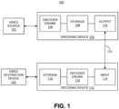
- FIG. 1 is a block diagram illustrating an example of a system 100 including an encoding device 104 and a decoding device 112.
- the encoding device 104 may be part of a source device, and the decoding device 112 may be part of a receiving device.
- the source device and/or the receiving device may include an electronic device, such as a mobile or stationary telephone handset (e.g., smartphone, cellular telephone, or the like), a desktop computer, a laptop or notebook computer, a tablet computer, a set-top box, a television, a camera, a display device, a digital media player, a video gaming console, a video streaming device, an Internet Protocol (IP) camera, or any other suitable electronic device.
- IP Internet Protocol
- the source device and the receiving device may include one or more wireless transceivers for wireless communications.
- the coding techniques described herein are applicable to video coding in various multimedia applications, including streaming video transmissions (e.g., over the Internet), television broadcasts or transmissions, encoding of digital video for storage on a data storage medium, decoding of digital video stored on a data storage medium, or other applications.
- system 100 can support one-way or two-way video transmission to support applications such as video conferencing, video streaming, video playback, video broadcasting, gaming, and/or video telephony.
- the encoding device 104 can be used to encode video data using a video coding standard or protocol to generate an encoded video bitstream.
- Video coding standards include ITU-T H.261, ISO/IEC MPEG-1 Visual, ITU-T H.262 or ISO/IEC MPEG-2 Visual, ITU-T H.263, ISO/IEC MPEG-4 Visual and ITU-T H.264 (also known as ISO/IEC MPEG-4 AVC), including its Scalable Video Coding (SVC) and Multiview Video Coding (MVC) extensions.
- HEVC High-Efficiency Video Coding
- JCT-VC Joint Collaboration Team on Video Coding
- VCEG ITU-T Video Coding Experts Group
- MPEG ISO/IEC Moving Picture Experts Group
- MV-HEVC multiview extension to HEVC
- SHVC scalable extension to HEVC
- a video source 102 may provide the video data to the encoding device 104.
- the video source 102 may be part of the source device, or may be part of a device other than the source device.
- the video source 102 may include a video capture device (e.g., a video camera, a camera phone, a video phone, or the like), a video archive containing stored video, a video server or content provider providing video data, a video feed interface receiving video from a video server or content provider, a computer graphics system for generating computer graphics video data, a combination of such sources, or any other suitable video source.
- the video data from the video source 102 may include one or more input pictures or frames.
- a picture or frame is a still image that is part of a video.
- the encoder engine 106 (or encoder) of the encoding device 104 encodes the video data to generate an encoded video bitstream.
- an encoded video bitstream (or "video bitstream” or “bitstream”) is a series of one or more coded video sequences.
- a coded video sequence (CVS) includes a series of access units (AUs) starting with an AU that has a random access point picture in the base layer and with certain properties up to and not including a next AU that has a random access point picture in the base layer and with certain properties.
- the certain properties of a random access point picture that starts a CVS may include a RASL flag (e.g., NoRaslOutputFlag) equal to 1. Otherwise, a random access point picture (with RASL flag equal to 0) does not start a CVS.
- An access unit (AU) includes one or more coded pictures and control information corresponding to the coded pictures that share the same output time. Coded slices of pictures are encapsulated in the bitstream level into data units called network abstraction layer (NAL) units.
- NAL network abstraction layer
- an HEVC video bitstream may include one or more CVSs including NAL units. Each of the NAL units has a NAL unit header.
- VCL NAL units Two classes of NAL units exist in the HEVC standard, including video coding layer (VCL) NAL units and non-VCL NAL units.
- VCL NAL unit includes one slice or slice segment (described below) of coded picture data
- non-VCL NAL unit includes control information that relates to one or more coded pictures.
- a NAL unit can be referred to as a packet.
- An HEVC AU includes VCL NAL units containing coded picture data and non-VCL NAL units (if any) corresponding to the coded picture data.
- NAL units may contain a sequence of bits forming a coded representation of the video data (e.g., an encoded video bitstream, a CVS of a bitstream, or the like), such as coded representations of pictures in a video.
- the encoder engine 106 generates coded representations of pictures by partitioning each picture into multiple slices.
- a slice is independent of other slices so that information in the slice is coded without dependency on data from other slices within the same picture.
- a slice includes one or more slice segments including an independent slice segment and, if present, one or more dependent slice segments that depend on previous slice segments.
- the slices are then partitioned into coding tree blocks (CTBs) of luma samples and chroma samples.
- CTBs coding tree blocks
- a CTB of luma samples and one or more CTBs of chroma samples, along with syntax for the samples, are referred to as a coding tree unit (CTU).
- a CTU is the basic processing unit for HEVC encoding.
- a CTU can be split into multiple coding units (CUs) of varying sizes.
- a CU contains luma and chroma sample arrays that are referred to as coding blocks (CBs).
- a size of a CU corresponds to a size of the coding mode and may be square in shape.
- a size of a CU may be 8 x 8 samples, 16 x 16 samples, 32 x 32 samples, 64 x 64 samples, or any other appropriate size up to the size of the corresponding CTU.
- the phrase "N x N" is used herein to refer to pixel dimensions of a video block in terms of vertical and horizontal dimensions (e.g., 8 pixels x 8 pixels).
- the pixels in a block may be arranged in rows and columns. In some embodiments, blocks may not have the same number of pixels in a horizontal direction as in a vertical direction.
- Syntax data associated with a CU may describe, for example, partitioning of the CU into one or more PUs.
- Partitioning modes may differ between whether the CU is intra-prediction mode encoded or inter-prediction mode encoded.
- PUs may be partitioned to be non-square in shape.
- Syntax data associated with a CU may also describe, for example, partitioning of the CU into one or more TUs according to a CTU.
- a TU can be square or non-square in shape.
- transformations may be performed using transform units (TUs).
- TUs may vary for different CUs.
- the TUs may be sized based on the size of PUs within a given CU.
- the TUs may be the same size or smaller than the PUs.
- residual samples corresponding to a CU may be subdivided into smaller units using a quadtree structure known as residual quad tree (RQT).
- Leaf nodes of the RQT may correspond to TUs.
- Pixel difference values associated with the TUs may be transformed to produce transform coefficients.
- the transform coefficients may then be quantized by the encoder engine 106.
- the encoder engine 106 predicts each PU using a prediction mode.
- the prediction unit or prediction block is then subtracted from the original video data to get residuals (described below).
- a prediction mode may be signaled inside the bitstream using syntax data.
- a prediction mode may include intra-prediction (or intra-picture prediction) or inter-prediction (or inter-picture prediction).
- Intra-prediction utilizes the correlation between spatially neighboring samples within a picture.
- each PU is predicted from neighboring image data in the same picture using, for example, DC prediction to find an average value for the PU, planar prediction to fit a planar surface to the PU, direction prediction to extrapolate from neighboring data, or any other suitable types of prediction.
- Inter-prediction uses the temporal correlation between pictures in order to derive a motion-compensated prediction for a block of image samples.
- each PU is predicted using motion compensation prediction from image data in one or more reference pictures (before or after the current picture in output order). The decision whether to code a picture area using inter-picture or intra-picture prediction may be made, for example, at the CU level.
- the one or more slices of a picture are assigned a slice type.
- Slice types include an I slice, a P slice, and a B slice.
- An I slice is a slice of a picture that is only coded by intra-prediction, and therefore is independently decodable since the I slice requires only the data within the frame to predict any prediction unit or prediction block of the slice.
- a P slice (uni-directional predicted frames) is a slice of a picture that may be coded with intra-prediction and with uni-directional inter-prediction. Each prediction unit or prediction block within a P slice is either coded with Intra prediction or inter-prediction.
- the data defining the motion vector for a PU may describe, for example, a horizontal component of the motion vector ( ⁇ x), a vertical component of the motion vector ( ⁇ y), a resolution for the motion vector (e.g., integer precision, one-quarter pixel precision or one-eighth pixel precision), a reference picture to which the motion vector points, a reference index, a reference picture list (e.g., List 0, List 1, or List C) for the motion vector, or any combination thereof.
- the encoding device 104 may then perform transformation and quantization.
- the encoder engine 106 may calculate residual values corresponding to the PU. Residual values may comprise pixel difference values between the current block of pixels being coded (the PU) and the prediction block used to predict the current block (e.g., the predicted version of the current block). For example, after generating a prediction block (e.g., issuing inter-prediction or intra-prediction), the encoder engine 106 can generate a residual block by subtracting the prediction block produced by a prediction unit from the current block.
- the residual block includes a set of pixel difference values that quantify differences between pixel values of the current block and pixel values of the prediction block.
- the residual block may be represented in a two-dimensional block format (e.g., a two-dimensional matrix or array of pixel values). In such examples, the residual block is a two-dimensional representation of the pixel values.
- the encoder engine 106 may calculate residual data for the TUs of the CU.
- the PUs may comprise pixel data in the spatial domain (or pixel domain).
- the TUs may comprise coefficients in the transform domain following application of a block transform.
- the residual data may correspond to pixel difference values between pixels of the unencoded picture and prediction values corresponding to the PUs.
- Encoder engine 106 may form the TUs including the residual data for the CU, and may then transform the TUs to produce transform coefficients for the CU.
- the encoder engine 106 may perform quantization of the transform coefficients. Quantization provides further compression by quantizing the transform coefficients to reduce the amount of data used to represent the coefficients. For example, quantization may reduce the bit depth associated with some or all of the coefficients. In one example, a coefficient with an n-bit value may be rounded down to an m-bit value during quantization, with n being greater than m.
- the coded video bitstream includes quantized transform coefficients, prediction information (e.g., prediction modes, motion vectors, block vectors, or the like), partitioning information, and any other suitable data, such as other syntax data.
- the different elements of the coded video bitstream may then be entropy encoded by the encoder engine 106.
- the encoder engine 106 may utilize a predefined scan order to scan the quantized transform coefficients to produce a serialized vector that can be entropy encoded.
- encoder engine 106 may perform an adaptive scan. After scanning the quantized transform coefficients to form a vector (e.g., a one-dimensional vector), the encoder engine 106 may entropy encode the vector.
- the encoder engine 106 may use context adaptive variable length coding, context adaptive binary arithmetic coding, syntax-based context-adaptive binary arithmetic coding, probability interval partitioning entropy coding, or another suitable entropy encoding technique.
- an HEVC bitstream includes a group of NAL units, including VCL NAL units and non-VCL NAL units.
- VCL NAL units include coded picture data forming a coded video bitstream.
- a sequence of bits forming the coded video bitstream is present in VCL NAL units.
- Non-VCL NAL units may contain parameter sets with high-level information relating to the encoded video bitstream, in addition to other information.
- a parameter set may include a video parameter set (VPS), a sequence parameter set (SPS), and a picture parameter set (PPS). Examples of goals of the parameter sets include bit rate efficiency, error resiliency, and providing systems layer interfaces.
- Each slice references a single active PPS, SPS, and VPS to access information that the decoding device 112 may use for decoding the slice.
- An identifier may be coded for each parameter set, including a VPS ID, an SPS ID, and a PPS ID.
- An SPS includes an SPS ID and a VPS ID.
- a PPS includes a PPS ID and an SPS ID.
- Each slice header includes a PPS ID. Using the IDs, active parameter sets can be identified for a given slice.
- a PPS includes information that applies to all slices in a given picture. Because of this, all slices in a picture refer to the same PPS. Slices in different pictures may also refer to the same PPS.
- An SPS includes information that applies to all pictures in a same coded video sequence (CVS) or bitstream.
- a coded video sequence is a series of access units (AUs) that starts with a random access point picture (e.g., an instantaneous decode reference (IDR) picture or broken link access (BLA) picture, or other appropriate random access point picture) in the base layer and with certain properties (described above) up to and not including a next AU that has a random access point picture in the base layer and with certain properties (or the end of the bitstream).
- a random access point picture e.g., an instantaneous decode reference (IDR) picture or broken link access (BLA) picture, or other appropriate random access point picture
- the information in an SPS may not change from picture to picture within a coded video sequence.
- Pictures in a coded video sequence may use the same SPS.
- the VPS includes information that applies to all layers within a coded video sequence or bitstream.
- the VPS includes a syntax structure with syntax elements that apply to entire coded video sequences.
- the VPS, SPS, or PPS may be transmitted in-band with the encoded bitstream.
- the VPS, SPS, or PPS may be transmitted out-of-band in a separate transmission than the NAL units containing coded video data.
- a video bitstream can also include Supplemental Enhancement Information (SEI) messages.
- SEI Supplemental Enhancement Information
- an SEI NAL unit can be part of the video bitstream.
- an SEI message can contain information that is not needed by the decoding process.
- the information in an SEI message may not be essential for the decoder to decode the video pictures of the bitstream, but the decoder can be use the information to improve the display or processing of the pictures (e.g., the decoded output).
- the information in an SEI message can be embedded metadata. In one illustrative example, the information in an SEI message could be used by decoder-side entities to improve the viewability of the content.
- certain application standards may mandate the presence of such SEI messages in the bitstream so that the improvement in quality can be brought to all devices that conform to the application standard (e.g., the carriage of the frame-packing SEI message for frame-compatible plano-stereoscopic 3DTV video format, where the SEI message is carried for every frame of the video, handling of a recovery point SEI message, use of pan-scan scan rectangle SEI message in DVB, in addition to many other examples).
- the application standard e.g., the carriage of the frame-packing SEI message for frame-compatible plano-stereoscopic 3DTV video format, where the SEI message is carried for every frame of the video, handling of a recovery point SEI message, use of pan-scan scan rectangle SEI message in DVB, in addition to many other examples).
- the output 110 of the encoding device 104 may send the NAL units making up the encoded video bitstream data over the communications link 120 to the decoding device 112 of the receiving device.
- the input 114 of the decoding device 112 may receive the NAL units.
- the communications link 120 may include a channel provided by a wireless network, a wired network, or a combination of a wired and wireless network.
- a wireless network may include any wireless interface or combination of wireless interfaces and may include any suitable wireless network (e.g., the Internet or other wide area network, a packet-based network, WiFi TM , radio frequency (RF), UWB, WiFi-Direct, cellular, Long-Term Evolution (LTE), WiMax TM , or the like).
- a wired network may include any wired interface (e.g., fiber, ethernet, powerline ethernet, ethernet over coaxial cable, digital signal line (DSL), or the like).
- the wired and/or wireless networks may be implemented using various equipment, such as base stations, routers, access points, bridges, gateways, switches, or the like.
- the encoded video bitstream data may be modulated according to a communication standard, such as a wireless communication protocol, and transmitted to the receiving device.
- the encoding device 104 may store encoded video bitstream data in storage 108.
- the output 110 may retrieve the encoded video bitstream data from the encoder engine 106 or from the storage 108.
- Storage 108 may include any of a variety of distributed or locally accessed data storage media.
- the storage 108 may include a hard drive, a storage disc, flash memory, volatile or non-volatile memory, or any other suitable digital storage media for storing encoded video data.
- the decoding device 112 may output the decoded video to a video destination device 122, which may include a display or other output device for displaying the decoded video data to a consumer of the content.
- the video destination device 122 may be part of the receiving device that includes the decoding device 112. In some aspects, the video destination device 122 may be part of a separate device other than the receiving device.
- the video encoding device 104 and/or the video decoding device 112 may be integrated with an audio encoding device and audio decoding device, respectively.
- the video encoding device 104 and/or the video decoding device 112 may also include other hardware or software that is necessary to implement the coding techniques described above, such as one or more microprocessors, digital signal processors (DSPs), application specific integrated circuits (ASICs), field programmable gate arrays (FPGAs), discrete logic, software, hardware, firmware or any combinations thereof.
- DSPs digital signal processors
- ASICs application specific integrated circuits
- FPGAs field programmable gate arrays
- the video encoding device 104 and the video decoding device 112 may be integrated as part of a combined encoder/decoder (codec) in a respective device.
- codec combined encoder/decoder
- Extensions to the HEVC standard include the Multiview Video Coding extension, referred to as MV-HEVC, and the Scalable Video Coding extension, referred to as SHVC.
- MV-HEVC Multiview Video Coding extension
- SHVC Scalable Video Coding extension
- the MV-HEVC and SHVC extensions share the concept of layered coding, with different layers being included in the encoded video bitstream.
- Each layer in a coded video sequence is addressed by a unique layer identifier (ID).
- ID may be present in a header of a NAL unit to identify a layer with which the NAL unit is associated.
- MV-HEVC different layers can represent different views of the same scene in the video bitstream.
- SHVC different scalable layers are provided that represent the video bitstream in different spatial resolutions (or picture resolution) or in different reconstruction fidelities.
- the base layer may conform to a profile of the first version of HEVC, and represents the lowest available layer in a bitstream.
- the enhancement layers have increased spatial resolution, temporal resolution or frame rate, and/or reconstruction fidelity (or quality) as compared to the base layer.
- the enhancement layers are hierarchically organized and may (or may not) depend on lower layers.
- the different layers may be coded using a single standard codec (e.g., all layers are encoded using HEVC, SHVC, or other coding standard).
- different layers may be coded using a multi-standard codec.
- a base layer may be coded using AVC, while one or more enhancement layers may be coded using SHVC and/or MV-HEVC extensions to the HEVC standard.
- a layer includes a set of VCL NAL units and a corresponding set of non-VCL NAL units.
- the NAL units are assigned a particular layer ID value.
- Layers can be hierarchical in the sense that a layer may depend on a lower layer.
- a layer set refers to a set of layers represented within a bitstream that are self-contained, meaning that the layers within a layer set can depend on other layers in the layer set in the decoding process, but do not depend on any other layers for decoding. Accordingly, the layers in a layer set can form an independent bitstream that can represent video content.
- the set of layers in a layer set may be obtained from another bitstream by operation of a sub-bitstream extraction process.
- a layer set may correspond to the set of layers that is to be decoded when a decoder wants to operate according to certain parameters.
- Dynamic range defines the range of luminosity available in video content or the range of luminosity that a display can reproduce.
- SDR Standard Dynamic Range
- SDR describes the dynamic range of video and the dynamic range capability of a display using a conventional gamma curve, which is based on the limits of a cathode ray tube display.
- SDR is mastered typically for a maximum luminance of 100 candelas per square meter (cd/m 2 ), although some displays may choose to display SDR content at a peak luminance that is higher than 100 cd/m 2 .
- High Dynamic Range (HDR) describes video or displays with a greater range of luminosity than SDR video or displays.
- HDR video content can allow for a luminance of 2,000 cd/m2. HDR video content can thus allow a display to provide peak-luminance levels.
- FIG. 2 is a diagram showing the standard dynamic range (SDR) color gamut as triangle 204, which is based on the BT.709 color red, green and blue color primaries.
- SDR standard dynamic range
- UHDTV ultra-high definition television
- FIG. 2 also depicts the so-called spectrum locus (delimited by the tongue-shaped area 206), representing limits of natural colors (e.g., the colors that are visible to the human eye).
- SDR standard dynamic range
- UHDTV ultra-high definition television
- FIG. 2 also depicts the so-called spectrum locus (delimited by the tongue-shaped area 206), representing limits of natural colors (e.g., the colors that are visible to the human eye).
- HDR provides an increase in the dynamic range of a picture (relating to luminance) over lower dynamic ranges (e.g., a dynamic range provided by SDR).
- WCG Wide color gamut
- the color volume occupied by the content it is beneficial to know the color volume occupied by the content. For example, it may beneficial to know the color volume when the content is to be converted from one color volume to another color volume (e.g., from a color volume that the content occupies to a smaller color volume (smaller with respect to the color volume occupied by the content) that is supported by a display).
- the information of the color gamut and the color volume is beneficial in describing color volume conversion functions used to convert a first color volume to a second color volume. Knowledge of how the color volume for a particular content varies may also be used to specify one or more post-processing steps on the content.
- consumer display-side devices may have different capabilities than the capabilities of displays in a production studio or other source of video content.
- the display-side devices need to be able to map received content to best fit their displays.
- a television network may send a movie to a Samsung television and a Sony television.
- video content providers may mandate that devices use the existing color mapping algorithms.
- manufacturers of the different devices may not want to use mandated mapping information, and may prefer to develop their own mapping algorithms for their own devices.
- the Samsung and Sony devices may have different display capabilities and characteristics, and may use different applications or programs to map the content according to the display capabilities and characteristics. In such cases, the different devices may not be tuned to use the mandated mapping information.
- Systems and methods are described herein for generating and processing messages containing information describing the color volume of video content.
- the messages can be defined for video coding and video application standards, such as H.265/HEVC, H.264/AVC, BDA, MPEG, DVB or others.
- One or more of the techniques and methods described herein may be applied independently, or in combination with others.
- One or more syntax elements associated within a particular iteration of a loop may be associated with all the iterations of the loop and signaled outside the loop, or vice versa.
- a content color volume message can be generated by an encoding device (e.g., encoding device 104) and can be received and processed by a decoding device (e.g., decoding device 112), a player device, a display device, and/or any other display-side or client-side device.
- a video encoding device (or other transmission-side device) can determine the color volume of content being encoded.
- the color volume can be determined using the maximum value of each color primary coordinate in a picture and the maximum luminance of the picture (e.g., in the red-green-blue (RGB) space, the xyY color space, or other suitable color spaces). Other suitable techniques for determining color volume can also be used.
- the encoding device can generate a content color volume message with (e.g., including) content color volume information describing the color volume of the video content.
- a client-side device e.g., a video decoding device, a video player device, a video display device, a combination thereof, or other suitable device
- a device with a display e.g., a television, a mobile device, or other suitable device
- Any suitable device can use the content color volume information to render or display the video content, without being restricted to any particular application or program. For instance, instead of mandating (i.e., requiring) a device to use a particular algorithm or program for mapping or converting the video content to the display, the characteristics of the video content in terms of the color volume can be provided to the device, and the device can map or convert the video so as to provide the best quality video for its display using its own mapping or other color-based algorithm.
- the content color volume information in the content color volume message can also be used for purposes other than color mapping, such as converting between different luminances (e.g., converting from HDR to low dynamic range (LDR) for a display that can only display LDR content), or other color-based functions.
- the content color volume information within the content color volume message may be used by the display-side device to determine that the display-side device does not have to do any processing other than the usual conversion chain used to render and/or display the content. For instance, when the content color volume message describes that the content meets a specific criteria, for example, that the content occupies a color volume that is smaller than the color volume supported by the display, or nearly the same size as that of the display, the display-side device may determine that the display-side device does not require additional processing to optimally render and/or display the content. Avoiding conversion processes/mapping algorithms that are outside the usual chain of processing can be very beneficial for devices that are sensitive to power consumption needs (e.g., mobile devices or other suitable devices). Avoiding additional processing may also provide a benefit of avoiding delays associated with setting up and/or performing modified conversion processes. For instance, displaying content while enabling the additional processing may result in impaired presentation such as frame freezes.
- the color volume of the video content described by the content color volume message can include a color gamut of the video content and the minimum and maximum luminances that are occupied by the video content.
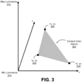
- FIG. 3 is a diagram illustrating an example of a content color gamut 302 of video content.
- the x-axis and the y-axis of FIG. 3-FIG. 7 correspond to the x-axis and the y-axis of the graph shown in FIG. 2 , with the different color gamuts (color gamuts 302, 402, 422, 432, 502, 522, 532, 622A-622C, and 722A-722C) including colors within the color locus 206.
- a minimum luminance value 314 and a maximum luminance value 312 are the luminance values within which the video content is restricted. For example, the minimum luminance value 314 and a maximum luminance value 312 define a range of luminance values of the video content.
- the content color gamut 302 includes an area footprint defining the possible chrominance (or color) values of the video content at a particular luminance value in the range of luminance values defined by the minimum luminance value 314 and a maximum luminance value 312.
- Chromaticity coordinates of the color primaries that describe the color gamut 302 of the video content can be identified. For example, a chromaticity coordinate x B , y B 316 for the blue color primary, a chromaticity coordinate x R , y R 318 for the red color primary, and a chromaticity coordinate x G , y G 320 for the green color primary are shown in FIG. 3 .
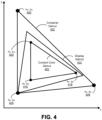
- FIG. 4 is a diagram illustrating examples of a color gamut 402 of video content, a color gamut 422 of a display on which the video content is to be presented, and a color gamut 432 of a container in which the video content is coded.
- An illustrative example of the container gamut 432 includes the BT.2020 color gamut.
- the video content can include the colors that are within the color gamut of the BT.2020 container.
- the video usability information (VUI) included in or with a video bitstream may contain parameters that indicate the container gamut 432.
- the VUI can include information specifying that the container is a BT.2020 container.
- a client-side device Based on the container information in the VUI, a client-side device will know to use the coordinate x B , y B 426 for the blue color primary of the BT.2020 container, the coordinate x R , y R 428 for the red color primary of the BT.2020 container, and the coordinate x G , y G 430 for the green color primary of the BT.2020 container, as shown in FIG. 4 .
- the VUI can be included in a parameter set of the bitstream, such as the SPS or VPS.
- the display color gamut 522 does not encompass all of the colors covered by the content color gamut 502.
- the chromaticity coordinate x G , y G 520 of the green color primary of the content color gamut 502 relates to a green color that the display cannot present.
- the display has to map or convert the received video content into a color that is within the display color gamut 522.
- the display will have to map some of the luminance values of the video content to the luminance capabilities of the display.
- the device can use the content color volume information of the content color volume message to perform the mappings. For example, the device can derive the content color volume of the video content based on one more syntax elements of the message signalled in an encoded video bitstream.
- the display can choose a second color in the display color gamut 522 (e.g. a color that is closest in Euclidean distance in an xy-space, a color that is towards the white point of the display (as shown in FIG. 2 ), or other suitable color) and can use the chrominance values of the second color to display the first color.
- a second color in the display color gamut 522 e.g. a color that is closest in Euclidean distance in an xy-space, a color that is towards the white point of the display (as shown in FIG. 2 ), or other suitable color
- the display can be certain what would be the result of the mapping algorithm.
- the display can also choose another algorithm to perform a one-to-one mapping of the entire content color gamut 502 to outside the display color gamut 522.
- the presence of the content color volume message with the content color volume information enables the display-side device to determine what processing, if any, needs to be done.
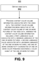
- FIG. 9 is a flowchart illustrating an example of a process 900 of processing video data using one or more of the techniques described herein.
- the process 900 includes obtaining the video data.
- the video data can include video pictures captured by an image capture device.
- the video data can include encoded video data (e.g., an encoded video bitstream).
- the video data can include decoded video data.
- processing the video data can include generating the content color volume information.
- processing the content color volume information can further include generating a content color volume message and including the content color volume information in the content color volume message.
- the process 900 can include transmitting the content color volume message to a client device (e.g., in an encoded video bitstream or separately from the encoded video bitstream).
- processing the content color volume information can include decoding the content color volume information from the encoded video data and applying the content color volume information to the decoded video data.
- processing the content color volume information can include applying the content color volume information to the decoded video data.
- the device performing the processing e.g., a player device, a display device, or other suitable device
- the first luminance value includes a normalized minimum luminance value
- the second luminance value includes a normalized maximum luminance value, as previously described.
- the first luminance value is used to derive a minimum luminance value of the one or more pictures.
- the second luminance value is used to derive a maximum luminance value of the one or more pictures.
- a fixed point (how a syntax element is signaled) to floating point (in nits) conversion technique can be used to derive the minimum and/or maximum luminance values. Any other suitable techniques can also be used.
- the first luminance value is the minimum luminance value, in which case the device can directly use the first luminance value as the minimum luminance value.
- the second luminance value is the maximum luminance value, in which case the device can directly use the second luminance value as the maximum luminance value.
- a syntax element is provided with the video data.
- the syntax element indicates that a subset of the content color volume information is signaled.
- the syntax element can specify that a subset of syntax elements used to derive the content color volume is present in the content color volume message.
- some values of the syntax element are used to indicate that a subset of the syntax elements used to derive the content color volume may be signalled.
- Other values of the syntax element can be used to indicate that a subset of the syntax elements used to derive the content color volume may not be signalled.
- the syntax element is related to syntax elements ccv_min_luminance_value_present_flag, ccv_max_luminance_value_present_flag, and ccv_avg_luminance_value_present_flag in the JCTVC-Z1005 standard text.
- the content color volume information is signaled using one or more syntax elements of a supplemental enhancement information (SEI) message.
- SEI supplemental enhancement information
- a content color volume SEI message can be generated that includes the content color volume information.
- the one or more chromaticity coordinates include three chromaticity coordinates specifying three color primaries of the one or more pictures.
- the three chromaticity coordinates include a green chromaticity coordinate for a green color primary of the one or more pictures, a red chromaticity coordinate for a red color primary of the one or more pictures, and a chromaticity blue coordinate for a blue color primary of the one or more pictures.
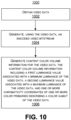
- FIG. 10 is a flowchart illustrating an example of a process 1000 of encoding video data using one or more of the techniques described herein.
- the process 1000 includes obtaining the video data.
- the video data can include video pictures captured by an image capture device.
- the video data can be obtained from the image capture device or from a storage device that stores the video data.
- the process 1000 includes generating, using the video data, an encoded video bitstream.
- the video bitstream can be generated using the encoding techniques described herein.
- the process 1000 includes generating content color volume information for the video data.
- the content color volume information includes a first luminance value associated with a minimum luminance of the video data, a second luminance value associated with a maximum luminance of the video data, and one or more chromaticity coordinates of one or more color primaries describing a color gamut of the video data.
- the process 1000 includes generating a content color volume message.
- the process 1000 can include the content color volume information in the content color volume message.
- the process 1000 can include transmitting the content color volume message to a client device (e.g., a decoder device, a player device, a display device, or the like).
- the process 1000 includes transmitting the encoded video bitstream to the client device.
- the content color volume message is transmitted in the encoded video bitstream (e.g., as one or more packet or NAL units of the bitstream).
- the content color volume message is transmitted separately from the encoded video bitstream.
- the content color volume information can be generated at a picture-level, in which case the content color volume information describes the content color volume of a picture.
- the content color volume information can be generated at other video content levels, such as on a block basis, only for certain pictures of a bitstream (e.g., every n number of pictures, at every random access picture, or other subset of pictures), on a sequence-level basis (for a CVS), signaled on a layer-basis, signaled for the entire bitstream, or a combination thereof.
- the first luminance value includes a normalized minimum luminance value
- the second luminance value includes a normalized maximum luminance value, as previously described.
- the first luminance value is used to derive a minimum luminance value of the one or more pictures.
- the second luminance value is used to derive a maximum luminance value of the one or more pictures.
- a fixed point (how a syntax element is signaled) to floating point (in nits) conversion technique can be used to derive the minimum and/or maximum luminance values. Any other suitable techniques can also be used.
- the first luminance value is the minimum luminance value, in which case the device can directly use the first luminance value as the minimum luminance value.
- the second luminance value is the maximum luminance value, in which case the device can directly use the second luminance value as the maximum luminance value.
- a syntax element is provided with the video data.
- the syntax element indicates that a subset of the content color volume information is signaled.
- the syntax element can specify that a subset of syntax elements used to derive the content color volume is present in the content color volume message.
- some values of the syntax element are used to indicate that a subset of the syntax elements used to derive the content color volume may be signalled.
- Other values of the syntax element can be used to indicate that a subset of the syntax elements used to derive the content color volume may not be signalled.
- the syntax element is related to syntax elements ccv_min_luminance_value_present_flag, ccv_max_luminance_value_present_flag, and ccv_avg_luminance_value_present_flag in the JCTVC-Z1005 standard text.
- the content color volume information is signaled using one or more syntax elements of a supplemental enhancement information (SEI) message.
- SEI supplemental enhancement information
- a content color volume SEI message can be generated that includes the content color volume information.
- the one or more chromaticity coordinates include three chromaticity coordinates specifying three color primaries of the one or more pictures.
- the three chromaticity coordinates include a green chromaticity coordinate for a green color primary of the one or more pictures, a red chromaticity coordinate for a red color primary of the one or more pictures, and a chromaticity blue coordinate for a blue color primary of the one or more pictures.
- FIG. 11 is a flowchart illustrating an example of another process 1100 of processing video data using one or more of the techniques described herein.
- the process 1100 includes obtaining the video data.
- the video data can include encoded video data (e.g., an encoded video bitstream).
- the video data can include decoded video data.
- the process 1100 includes obtaining content color volume information for one or more pictures of the video data.
- the content color volume information includes a first luminance value associated with a minimum luminance of the one or more pictures, a second luminance value associated with a maximum luminance of the one or more pictures, and one or more chromaticity coordinates of one or more color primaries describing a color gamut of the one or more pictures.
- content_color_volume_id contains an identifying number that may be used to identify the purpose of the SEI message.
- the value of content_color_volume_id shall be in the range of 0 to 2 32 - 2, inclusive.
- variable ContentVolumeLuminanceRange[ ], for i in the range of 0 to ContentVolumeNumLumRanges, inclusive, is derived as follows: where "/" operation indicates division without rounding to the integer.
- content_volume_num_chrom[ i ] specifies the number of chromaticities associated with the i-th luminance range that is used to describe the color volume of the content.
- the value of content_volume_num_chrom[ i ] shall be in the range of 0 to 15, inclusive. When not present, the value of content_volume_num_chrom[ i ] is inferred to be equal to 3.
- content_volume_chrom_x [ i ][ j ] and content_volume_chrom_y [ i ][ j ] specify the normalized x and y chromaticity coordinates, respectively, of the j-th chromaticity coordinate that is used to derive an estimate of the color volume for the i-th luminance value in increments of 0.00002, according to the CIE 1931 definition of x and y as specified in ISO 11664-1 (see also ISO 11664-3 and CIE 15).
- the values of content_volume_chrom_x[ i ][ j ] and content_volume_chrom_y[ i ][ j ] shall be in the range of 0 to 50 000, inclusive.
- the values of content_volume_chrom_x[ i ][ c ] and content_volume_chrom_y[ i ][ c ] are inferred to be equal to content_gamut_primary_x[ c ] and content_gamut_primary_y[ c ], respectively, for c in the range of 0 to content_volum_num_chrom[ i ] - 1, inclusive, and i in the range of 0 to ContentVolumeNumLumRanges, inclusive.
- convexRegion[ i ] refer to the two-dimensional convex hull of the chromaticity coordinates content_volume_chrom_x[ i ][ j ] and content_volume_chrom_y[ i ][ j ] for j in the range of 0 to content_volume_num_chrom[ i ] - 1, inclusive.
- the color volume is derived as follows:
- one or more implicit color volume representations and one or more explicit color volume representations are signalled, including a syntax element indicating a number of volume representations and an indicator specifying the type of volume representation indicated.
- the terms color and colour have the same meaning in this document.
- the content colour volume SEI message indicates the colour volume of the content that may be utilized by display devices to map the content according to the display specifications.
- a conversion process is conducted to transform the decoded video to the representation of the colour volume and the volume representation is then described by colour volume representations present in the SEI message.
- the colour_primaries, transfer _charactreristics, and matrix_coeffs are used to transform the decoded video in to the representation in linear light domain.
- content_colour_volume_id contains an identifying number that may be used to identify the purpose of the SEI message.
- the value of content_colour_volume_id shall be in the range of 0 to 2 32 - 2, inclusive.
- Values of content_colour_volume_id from 0 to 255 and from 512 to 2 31 - 1 may be used as determined by the application. Values of content_colour_volume_id from 256 to 511 and from 2 31 to 2 32 - 2 are reserved for future use by ITU-T
- content_colour_volume_persistence_cancel_flag 1 indicates that the SEI message cancels the persistence of any previous content colour volume SEI message in output order that applies to the current layer.
- content_colour_volume_persistence_cancel_flag 0 indicates that content colour volume information follows.
- content_gamut_primary_x [ c ] and content_gamut_primary_y [ c ] specify the normalized x and y chromaticity coordinates, respectively, of the colour primary component c, for c in the range of 0 to 2, inclusive, of the content gamut in increments of 0.00002, according to the CIE 1931 definition of x and y as specified in ISO 11664-1 (see also ISO 11664-3 and CIE 15).
- index value c equal to 0 should correspond to the green primary
- c equal to 1 should correspond to the blue primary
- c equal to 2 should correspond to the red colour primary (see also Annex E and Table E.3).
- the values of content_gamut_primaries_x[ c ] and content_gamut_primaries_y[ c ] shall be in the range of 0 to 50 000, inclusive.
- content_volume_min_lum_value specify a minimum luminance value that is used to specify the colour volume of the content.
- the values of content_volume_min_lum_value are in units of 0.0001 candelas per square metre.
- content_volume_max_lum_value specify a maximum luminance value that is used to specify the colour volume of the content.
- the values of content_volume_max_lum_value are in units of 0.0001 candelas per square metre.
- colour_volume_num_implicit_repn specifies the number of implicit volume representations of the content specified in the SEI message.
- the value of colour_volume_num_implicit_repn shall be in the range of 0 to 7, inclusive.
- the value of colour_volume_num_implicit_repn in the range of 8 to 255, inclusive, are reserved for future use by ITU-T
- colour_volume_implicit_repn_type [ i ] specifies the interpretation, as described in Table 1, of the syntax elements impl_vol_repn_primary_x[ i ][ ], impl _vol_repn_primary_y[ i ][ ], impl_vol_repn_primary_min[ i ][ ] and impl_vol_repn_primary_max[ i ][ ] and the variables NumValsRepn[ i ] and PrimariesPresentFlag[ i ].
- the value of colour_volume_implicit_repn_type[ i ] shall be in the range of 0 to 6, inclusive.
- colour_volume_impl_repn_primary_x [ i ][ j ] and colour_volume_impl_repn_primary_y [ i ][ j ] specify the normalized x and y chromaticity coordinates, respectively, of the colour primary component c for the primary colour volume representation as interpreted from Table 1 in increments of 0.00002, according to the CIE 1931 definition of x and y as specified in ISO 11664-1 (see also ISO 11664-3 and CIE 15). The interpretation of index value to each primary is as specified in Table 1.
- colour_volume_impl_repn_primary_x[ i ][ j ] and colour_volume_impl_repn_primary_y[ i ][ j ] shall be in the range of 0 to 50 000, inclusive.
- colour_volume_impl_primary_min [ i ][ j ] and colour_volume_ impl_primary_max [ i ][ j ] specify the nominal maximum and minimum values, respectively, of the signals after conversion into the corresponding colour space, in units of 0.0001 candelas per square metre, where the colour space is specified in Table 1.
- colour_volume_impl_primary_min[ i ][ j ] shall be less than colour_volume_impl_primary_max[ i ][ j ].
- colour_volume _ num _ explicit_repn specifies the number of explicit volume representations of the content specified in the SEI message.
- the value of colour_volume _num_explicit_repn shall be in the range of 0 to 2, inclusive.
- the value of colour_volume_num_explicit_repn in the range of 3 to 255, inclusive, are reserved for future use by ITU-T
- colour_volume_expl_ranges_idc [ i ] 0 specifies that the syntax elements colour_volume_expl_range_value[ i ][ j ] are explicitly signalled.
- colour_volume_expl_ranges_idc[ i ] 1 or 2 specifies that the syntax element colour_volume_expl_range_value[ i ][ j ] for j in the range of 1 to ColourVolumeExplNumRanges[ i ] - 1, inclusive, are not explicitly signalled.
- colour_volume_expl_coord_1 [ i ][ j ][ k ] and colour_volume_expl _coord_2 [ i ][ j ][ k ] specify the coordinates of the second and third components, respectively, of the k-th coordinate corresponding to the j-th range that is used to derive an estimate of the colour volume in increments of 0.00002.
- the values of colour_volume_expl_coord_1[ i ][ j ][ k ] and colour_volume_expl_coord_2[ i ][ j ][ k ] shall be in the range of 0 to 50 000, inclusive.
- the source device includes a video source, a video encoder, and a output interface.
- the destination device may include an input interface, a video decoder, and a display device.
- the video encoder of source device may be configured to apply the techniques disclosed herein.
- a source device and a destination device may include other components or arrangements.
- the source device may receive video data from an external video source, such as an external camera.
- the destination device may interface with an external display device, rather than including an integrated display device.
- Motion compensation performed by motion compensation unit 44, may involve fetching or generating the predictive block based on the motion vector determined by motion estimation, possibly performing interpolations to sub-pixel precision.
- motion compensation unit 44 may locate the predictive block to which the motion vector points in a reference picture list.
- the encoding device 104 forms a residual video block by subtracting pixel values of the predictive block from the pixel values of the current video block being coded, forming pixel difference values.
- the pixel difference values form residual data for the block, and may include both luma and chroma difference components.
- Summer 50 represents the component or components that perform this subtraction operation.
- Motion compensation unit 44 may also generate syntax elements associated with the video blocks and the video slice for use by the decoding device 112 in decoding the video blocks of the video slice.
- Intra-prediction processing unit 46 may intra-predict a current block, as an alternative to the inter-prediction performed by motion estimation unit 42 and motion compensation unit 44, as described above. In particular, intra-prediction processing unit 46 may determine an intra-prediction mode to use to encode a current block. In some examples, intra-prediction processing unit 46 may encode a current block using various intra-prediction modes, e.g., during separate encoding passes, and intra-prediction unit processing 46 may select an appropriate intra-prediction mode to use from the tested modes.
- intra-prediction processing unit 46 may calculate rate-distortion values using a rate-distortion analysis for the various tested intra-prediction modes, and may select the intra-prediction mode having the best rate-distortion characteristics among the tested modes.
- Rate-distortion analysis generally determines an amount of distortion (or error) between an encoded block and an original, unencoded block that was encoded to produce the encoded block, as well as a bit rate (that is, a number of bits) used to produce the encoded block.
- Intra-prediction processing unit 46 may calculate ratios from the distortions and rates for the various encoded blocks to determine which intra-prediction mode exhibits the best rate-distortion value for the block.
- intra-prediction processing unit 46 may provide information indicative of the selected intra-prediction mode for the block to entropy encoding unit 56.
- Entropy encoding unit 56 may encode the information indicating the selected intra-prediction mode.
- the encoding device 104 may include in the transmitted bitstream configuration data definitions of encoding contexts for various blocks as well as indications of a most probable intra-prediction mode, an intra-prediction mode index table, and a modified intra-prediction mode index table to use for each of the contexts.
- the bitstream configuration data may include a plurality of intra-prediction mode index tables and a plurality of modified intra-prediction mode index tables (also referred to as codeword mapping tables).
- the encoding device 104 forms a residual video block by subtracting the predictive block from the current video block.
- the residual video data in the residual block may be included in one or more TUs and applied to transform processing unit 52.
- Transform processing unit 52 transforms the residual video data into residual transform coefficients using a transform, such as a discrete cosine transform (DCT) or a conceptually similar transform.
- Transform processing unit 52 may convert the residual video data from a pixel domain to a transform domain, such as a frequency domain.
- entropy encoding unit 56 entropy encodes the quantized transform coefficients.
- entropy encoding unit 56 may perform context adaptive variable length coding (CAVLC), context adaptive binary arithmetic coding (CABAC), syntax-based context-adaptive binary arithmetic coding (SBAC), probability interval partitioning entropy (PIPE) coding or another entropy encoding technique.
- CAVLC context adaptive variable length coding
- CABAC context adaptive binary arithmetic coding
- SBAC syntax-based context-adaptive binary arithmetic coding
- PIPE probability interval partitioning entropy
- the encoded bitstream may be transmitted to the decoding device 112, or archived for later transmission or retrieval by the decoding device 112.
- Entropy encoding unit 56 may also entropy encode the motion vectors and the other syntax elements for the current video slice being coded.
- Inverse quantization unit 58 and inverse transform processing unit 60 apply inverse quantization and inverse transformation, respectively, to reconstruct the residual block in the pixel domain for later use as a reference block of a reference picture.
- Motion compensation unit 44 may calculate a reference block by adding the residual block to a predictive block of one of the reference pictures within a reference picture list. Motion compensation unit 44 may also apply one or more interpolation filters to the reconstructed residual block to calculate sub-integer pixel values for use in motion estimation.
- Summer 62 adds the reconstructed residual block to the motion compensated prediction block produced by motion compensation unit 44 to produce a reference block for storage in picture memory 64.
- the reference block may be used by motion estimation unit 42 and motion compensation unit 44 as a reference block to inter-predict a block in a subsequent video frame or picture.
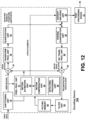
- the encoding device 104 of FIG. 12 represents an example of a video encoder configured to generate syntax for an encoded video bitstream.
- the encoding device 104 may, for example, generate syntax for a CRI SEI message, as described above.
- the encoding device 104 may perform any of the techniques described herein, including the processes described above with respect to FIG. 9 and FIG. 10 .
- the techniques of this disclosure have generally been described with respect to the encoding device 104, but as mentioned above, some of the techniques of this disclosure may also be implemented by post processing device 57.
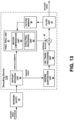
- FIG. 13 is a block diagram illustrating an example decoding device 112.
- the decoding device 112 includes an entropy decoding unit 80, prediction processing unit 81, inverse quantization unit 86, inverse transform processing unit 88, summer 90, filter unit 91, and picture memory 92.
- Prediction processing unit 81 includes motion compensation unit 82 and intra prediction processing unit 84.
- the decoding device 112 may, in some examples, perform a decoding pass generally reciprocal to the encoding pass described with respect to the encoding device 104 from FIG. 12 .
- the decoding device 112 may perform any of the techniques described herein, including the processes described above with respect to FIG. 9 and FIG. 11 .
- the decoding device 112 receives an encoded video bitstream that represents video blocks of an encoded video slice and associated syntax elements sent by the encoding device 104.
- the decoding device 112 may receive the encoded video bitstream from the encoding device 104.
- the decoding device 112 may receive the encoded video bitstream from a network entity 79, such as a server, a media-aware network element (MANE), a video editor/splicer, or other such device configured to implement one or more of the techniques described above.
- Network entity 79 may or may not include the encoding device 104.
- network entity 79 may be implemented by network entity 79 prior to network entity 79 transmitting the encoded video bitstream to the decoding device 112.
- network entity 79 and the decoding device 112 may be parts of separate devices, while in other instances, the functionality described with respect to network entity 79 may be performed by the same device that comprises the decoding device 112.
- the entropy decoding unit 80 of the decoding device 112 entropy decodes the bitstream to generate quantized coefficients, motion vectors, and other syntax elements. Entropy decoding unit 80 forwards the motion vectors and other syntax elements to prediction processing unit 81.
- the decoding device 112 may receive the syntax elements at the video slice level and/or the video block level. Entropy decoding unit 80 may process and parse both fixed-length syntax elements and variable-length syntax elements in or more parameter sets, such as a VPS, SPS, and PPS.
- intra prediction processing unit 84 of prediction processing unit 81 may generate prediction data for a video block of the current video slice based on a signaled intra-prediction mode and data from previously decoded blocks of the current frame or picture.
- motion compensation unit 82 of prediction processing unit 81 produces predictive blocks for a video block of the current video slice based on the motion vectors and other syntax elements received from entropy decoding unit 80.
- the predictive blocks may be produced from one of the reference pictures within a reference picture list.
- the decoding device 112 may construct the reference frame lists, List 0 and List 1, using default construction techniques based on reference pictures stored in picture memory 92.
- Motion compensation unit 82 determines prediction information for a video block of the current video slice by parsing the motion vectors and other syntax elements, and uses the prediction information to produce the predictive blocks for the current video block being decoded. For example, motion compensation unit 82 may use one or more syntax elements in a parameter set to determine a prediction mode (e.g., intra- or inter-prediction) used to code the video blocks of the video slice, an inter-prediction slice type (e.g., B slice, P slice, or GPB slice), construction information for one or more reference picture lists for the slice, motion vectors for each inter-encoded video block of the slice, inter-prediction status for each inter-coded video block of the slice, and other information to decode the video blocks in the current video slice.
- a prediction mode e.g., intra- or inter-prediction
- an inter-prediction slice type e.g., B slice, P slice, or GPB slice
- construction information for one or more reference picture lists for the slice motion vectors for each inter-en
- Motion compensation unit 82 may also perform interpolation based on interpolation filters. Motion compensation unit 82 may use interpolation filters as used by the encoding device 104 during encoding of the video blocks to calculate interpolated values for sub-integer pixels of reference blocks. In this case, motion compensation unit 82 may determine the interpolation filters used by the encoding device 104 from the received syntax elements, and may use the interpolation filters to produce predictive blocks.
- Inverse quantization unit 86 inverse quantizes, or de-quantizes, the quantized transform coefficients provided in the bitstream and decoded by entropy decoding unit 80.
- the inverse quantization process may include use of a quantization parameter calculated by the encoding device 104 for each video block in the video slice to determine a degree of quantization and, likewise, a degree of inverse quantization that should be applied.
- Inverse transform processing unit 88 applies an inverse transform (e.g., an inverse DCT or other suitable inverse transform), an inverse integer transform, or a conceptually similar inverse transform process, to the transform coefficients in order to produce residual blocks in the pixel domain.
- the decoding device 112 After motion compensation unit 82 generates the predictive block for the current video block based on the motion vectors and other syntax elements, the decoding device 112 forms a decoded video block by summing the residual blocks from inverse transform processing unit 88 with the corresponding predictive blocks generated by motion compensation unit 82.
- Summer 90 represents the component or components that perform this summation operation.
- loop filters (either in the coding loop or after the coding loop) may also be used to smooth pixel transitions, or to otherwise improve the video quality.
- Filter unit 91 is intended to represent one or more loop filters such as a deblocking filter, an adaptive loop filter (ALF), and a sample adaptive offset (SAO) filter. Although filter unit 91 is shown in FIG.
- filter unit 91 may be implemented as a post loop filter.
- the decoded video blocks in a given frame or picture are then stored in picture memory 92, which stores reference pictures used for subsequent motion compensation.
- Picture memory 92 also stores decoded video for later presentation on a display device, such as video destination device 122 shown in FIG. 1 .
- Such configuration can be accomplished, for example, by designing electronic circuits or other hardware to perform the operation, by programming programmable electronic circuits (e.g., microprocessors, or other suitable electronic circuits) to perform the operation, or any combination thereof.
- programmable electronic circuits e.g., microprocessors, or other suitable electronic circuits
- the techniques described herein may also be implemented in electronic hardware, computer software, firmware, or any combination thereof. Such techniques may be implemented in any of a variety of devices such as general purposes computers, wireless communication device handsets, or integrated circuit devices having multiple uses including application in wireless communication device handsets and other devices. Any features described as modules or components may be implemented together in an integrated logic device or separately as discrete but interoperable logic devices. If implemented in software, the techniques may be realized at least in part by a computer-readable data storage medium comprising program code including instructions that, when executed, performs one or more of the methods described above.
- the computer-readable data storage medium may form part of a computer program product, which may include packaging materials.
- the computer-readable medium may comprise memory or data storage media, such as random access memory (RAM) such as synchronous dynamic random access memory (SDRAM), read-only memory (ROM), non-volatile random access memory (NVRAM), electrically erasable programmable read-only memory (EEPROM), FLASH memory, magnetic or optical data storage media, and the like.
- RAM random access memory
- SDRAM synchronous dynamic random access memory
- ROM read-only memory
- NVRAM non-volatile random access memory
- EEPROM electrically erasable programmable read-only memory
- FLASH memory magnetic or optical data storage media, and the like.
- the techniques additionally, or alternatively, may be realized at least in part by a computer-readable communication medium that carries or communicates program code in the form of instructions or data structures and that can be accessed, read, and/or executed by a computer, such as propagated signals or waves.
- the program code may be executed by a processor, which may include one or more processors, such as one or more digital signal processors (DSPs), general purpose microprocessors, an application specific integrated circuits (ASICs), field programmable logic arrays (FPGAs), or other equivalent integrated or discrete logic circuitry.
- DSPs digital signal processors
- ASICs application specific integrated circuits
- FPGAs field programmable logic arrays
- a general purpose processor may be a microprocessor; but in the alternative, the processor may be any conventional processor, controller, microcontroller, or state machine.
- a processor may also be implemented as a combination of computing devices, e.g., a combination of a DSP and a microprocessor, a plurality of microprocessors, one or more microprocessors in conjunction with a DSP core, or any other such configuration. Accordingly, the term "processor,” as used herein may refer to any of the foregoing structure, any combination of the foregoing structure, or any other structure or apparatus suitable for implementation of the techniques described herein. In addition, in some aspects, the functionality described herein may be provided within dedicated software modules or hardware modules configured for encoding and decoding, or incorporated in a combined video encoder-decoder (CODEC).
- CODEC combined video encoder-decoder
Landscapes
- Engineering & Computer Science (AREA)
- Multimedia (AREA)
- Signal Processing (AREA)
- Compression Or Coding Systems Of Tv Signals (AREA)
Applications Claiming Priority (5)
| Application Number | Priority Date | Filing Date | Title |
|---|---|---|---|
| US201662337844P | 2016-05-17 | 2016-05-17 | |
| US201662339665P | 2016-05-20 | 2016-05-20 | |
| US201662399304P | 2016-09-23 | 2016-09-23 | |
| US15/594,207 US11102495B2 (en) | 2016-05-17 | 2017-05-12 | Methods and systems for generating and processing content color volume messages for video |
| PCT/US2017/032674 WO2017200925A1 (en) | 2016-05-17 | 2017-05-15 | Methods and systems for generating and processing content color volume messages for video |
Publications (2)
| Publication Number | Publication Date |
|---|---|
| EP3459255A1 EP3459255A1 (en) | 2019-03-27 |
| EP3459255B1 true EP3459255B1 (en) | 2025-07-09 |
Family
ID=58995246
Family Applications (1)
| Application Number | Title | Priority Date | Filing Date |
|---|---|---|---|
| EP17727770.4A Active EP3459255B1 (en) | 2016-05-17 | 2017-05-15 | Methods and systems for generating and processing content color volume messages for video |
Country Status (9)
| Country | Link |
|---|---|
| US (1) | US11102495B2 (enExample) |
| EP (1) | EP3459255B1 (enExample) |
| JP (1) | JP2019517205A (enExample) |
| KR (1) | KR102464291B1 (enExample) |
| CN (1) | CN109076244B (enExample) |
| AU (1) | AU2017267544A1 (enExample) |
| BR (1) | BR112018073439A2 (enExample) |
| TW (1) | TW201806388A (enExample) |
| WO (1) | WO2017200925A1 (enExample) |
Families Citing this family (40)
| Publication number | Priority date | Publication date | Assignee | Title |
|---|---|---|---|---|
| US10225561B2 (en) * | 2015-10-08 | 2019-03-05 | Mediatek Inc. | Method and apparatus for syntax signaling in image and video compression |
| CN112822537B (zh) * | 2015-11-09 | 2023-07-11 | 交互数字Vc控股公司 | 使视频内容适应到显示特性的方法、设备及介质 |
| DK4072137T3 (da) * | 2016-10-05 | 2024-12-09 | Dolby Laboratories Licensing Corp | Meddelelse af information om kildefarvevolumen |
| US11533450B2 (en) | 2017-09-25 | 2022-12-20 | Comcast Cable Communications, Llc | Anti-piracy video transmission and display |
| AU2019333452B2 (en) | 2018-08-28 | 2023-06-15 | Huawei Technologies Co., Ltd. | Picture partitioning method and apparatus |
| US12444337B2 (en) | 2018-10-25 | 2025-10-14 | Baylor University | System and method for a multi-primary wide gamut color system |
| US10607527B1 (en) | 2018-10-25 | 2020-03-31 | Baylor University | System and method for a six-primary wide gamut color system |
| US11315467B1 (en) | 2018-10-25 | 2022-04-26 | Baylor University | System and method for a multi-primary wide gamut color system |
| US11189210B2 (en) | 2018-10-25 | 2021-11-30 | Baylor University | System and method for a multi-primary wide gamut color system |
| US11488510B2 (en) | 2018-10-25 | 2022-11-01 | Baylor University | System and method for a multi-primary wide gamut color system |
| US10950162B2 (en) | 2018-10-25 | 2021-03-16 | Baylor University | System and method for a six-primary wide gamut color system |
| US10997896B2 (en) | 2018-10-25 | 2021-05-04 | Baylor University | System and method for a six-primary wide gamut color system |
| US11373575B2 (en) | 2018-10-25 | 2022-06-28 | Baylor University | System and method for a multi-primary wide gamut color system |
| US11062638B2 (en) | 2018-10-25 | 2021-07-13 | Baylor University | System and method for a multi-primary wide gamut color system |
| US11532261B1 (en) | 2018-10-25 | 2022-12-20 | Baylor University | System and method for a multi-primary wide gamut color system |
| US11403987B2 (en) | 2018-10-25 | 2022-08-02 | Baylor University | System and method for a multi-primary wide gamut color system |
| US10950161B2 (en) | 2018-10-25 | 2021-03-16 | Baylor University | System and method for a six-primary wide gamut color system |
| US11475819B2 (en) | 2018-10-25 | 2022-10-18 | Baylor University | System and method for a multi-primary wide gamut color system |
| US11341890B2 (en) | 2018-10-25 | 2022-05-24 | Baylor University | System and method for a multi-primary wide gamut color system |
| US11289003B2 (en) | 2018-10-25 | 2022-03-29 | Baylor University | System and method for a multi-primary wide gamut color system |
| US11043157B2 (en) | 2018-10-25 | 2021-06-22 | Baylor University | System and method for a six-primary wide gamut color system |
| US11410593B2 (en) | 2018-10-25 | 2022-08-09 | Baylor University | System and method for a multi-primary wide gamut color system |
| US11289000B2 (en) | 2018-10-25 | 2022-03-29 | Baylor University | System and method for a multi-primary wide gamut color system |
| US11069279B2 (en) * | 2018-10-25 | 2021-07-20 | Baylor University | System and method for a multi-primary wide gamut color system |
| US11587491B1 (en) | 2018-10-25 | 2023-02-21 | Baylor University | System and method for a multi-primary wide gamut color system |
| US11030934B2 (en) | 2018-10-25 | 2021-06-08 | Baylor University | System and method for a multi-primary wide gamut color system |
| US11069280B2 (en) | 2018-10-25 | 2021-07-20 | Baylor University | System and method for a multi-primary wide gamut color system |
| US12475826B2 (en) | 2018-10-25 | 2025-11-18 | Baylor University | System and method for a multi-primary wide gamut color system |
| US12444334B2 (en) | 2018-10-25 | 2025-10-14 | Baylor University | System and method for a multi-primary wide gamut color system |
| US11037481B1 (en) | 2018-10-25 | 2021-06-15 | Baylor University | System and method for a multi-primary wide gamut color system |
| KR102842500B1 (ko) * | 2019-02-01 | 2025-08-06 | 삼성전자주식회사 | 고 동적 범위 콘텐트를 재생하는 전자 장치 및 그 방법 |
| US10990855B2 (en) * | 2019-06-13 | 2021-04-27 | Baidu Usa Llc | Detecting adversarial samples by a vision based perception system |
| US12022084B2 (en) * | 2019-06-21 | 2024-06-25 | Telefonaktiebolaget Lm Ericsson (Publ) | Video coding layer up-switching indication |
| CN115398898B (zh) | 2020-03-30 | 2025-05-09 | 字节跳动有限公司 | 视频编解码中的条带类型 |
| WO2022086629A1 (en) * | 2020-10-21 | 2022-04-28 | Baylor University | System and method for a multi-primary wide gamut color system |
| US11816819B2 (en) | 2021-06-03 | 2023-11-14 | Baylor University | System and method for displaying super saturated color |
| US11501419B1 (en) * | 2021-06-03 | 2022-11-15 | Baylor University | System and method for displaying super saturated color |
| US12462773B1 (en) * | 2022-02-11 | 2025-11-04 | Baylor University | Optimization of image perception for color vision deficiencies |
| CN116700646B (zh) * | 2022-12-19 | 2024-05-28 | 荣耀终端有限公司 | 图像色差处理方法和装置 |
| US12462772B1 (en) | 2024-06-20 | 2025-11-04 | 6P Color, Inc. | System and method for conversion from XYZ to multiple primaries using pseudo white points |
Citations (1)
| Publication number | Priority date | Publication date | Assignee | Title |
|---|---|---|---|---|
| EP3010231A1 (en) * | 2014-10-17 | 2016-04-20 | Thomson Licensing | Method for color mapping a video signal based on color mapping data and method of encoding a video signal and color mapping data and corresponding devices |
Family Cites Families (19)
| Publication number | Priority date | Publication date | Assignee | Title |
|---|---|---|---|---|
| US9571856B2 (en) | 2008-08-25 | 2017-02-14 | Microsoft Technology Licensing, Llc | Conversion operations in scalable video encoding and decoding |
| WO2010105036A1 (en) | 2009-03-13 | 2010-09-16 | Dolby Laboratories Licensing Corporation | Layered compression of high dynamic range, visual dynamic range, and wide color gamut video |
| WO2012036947A2 (en) | 2010-09-13 | 2012-03-22 | Dolby Laboratories Licensing Corporation | Data transmission using out-of-gamut color coordinates |
| KR102758666B1 (ko) | 2011-05-27 | 2025-01-22 | 돌비 레버러토리즈 라이쎈싱 코오포레이션 | 변하는 레벨들의 메타데이터을 포함하는 컬러 관리를 제어하기 위한 스케일러블 시스템들 |
| TWI586150B (zh) | 2012-06-29 | 2017-06-01 | 新力股份有限公司 | 影像處理裝置及非暫態電腦可讀儲存媒體 |
| WO2014045506A1 (en) | 2012-09-24 | 2014-03-27 | Sharp Kabushiki Kaisha | Video compression with color space scalability |
| JP2016530780A (ja) * | 2013-07-14 | 2016-09-29 | エルジー エレクトロニクス インコーポレイティド | デジタル放送システムにおける高品質の色感表現のための超高画質放送信号送受信方法及び装置 |
| CN105531992A (zh) * | 2013-09-06 | 2016-04-27 | Lg电子株式会社 | 用于在数字广播系统中发送和接收用于高动态范围呈现的超高清晰度广播信号的方法和装置 |
| CN118301359A (zh) * | 2013-10-07 | 2024-07-05 | Vid拓展公司 | 用于多层视频编码的组合可分级性处理 |
| HK1224469A1 (zh) | 2013-10-11 | 2017-08-18 | 夏普株式会社 | 颜色信息和色度信令 |
| WO2015056182A2 (en) * | 2013-10-15 | 2015-04-23 | Nokia Technologies Oy | Video encoding and decoding |
| KR101786414B1 (ko) * | 2013-12-13 | 2017-10-17 | 브이아이디 스케일, 인크. | 보간을 이용하는 루마 및 크로마의 위상 정렬을 위한 컬러 색역 스케일러블 비디오 코딩 디바이스 및 방법 |
| CN106031143A (zh) | 2014-02-21 | 2016-10-12 | 皇家飞利浦有限公司 | 颜色空间和用于视频的解码器 |
| EP3275190B1 (en) * | 2015-03-25 | 2024-04-17 | Dolby Laboratories Licensing Corporation | Chroma subsampling and gamut reshaping |
| EP3285261B1 (en) * | 2015-04-15 | 2024-06-05 | Sony Group Corporation | Playback device, playback method, and program |
| US9616957B2 (en) | 2015-07-10 | 2017-04-11 | Paul Yaffe | Motorcycle fairing adjustment member and assembly and method of adjusting a motorcycle fairing |
| JP6633739B2 (ja) * | 2015-08-20 | 2020-01-22 | エルジー エレクトロニクス インコーポレイティド | 放送信号送信装置、放送信号受信装置、放送信号送信方法、及び放送信号受信方法 |
| AU2015227469A1 (en) * | 2015-09-17 | 2017-04-06 | Canon Kabushiki Kaisha | Method, apparatus and system for displaying video data |
| US10140953B2 (en) * | 2015-10-22 | 2018-11-27 | Dolby Laboratories Licensing Corporation | Ambient-light-corrected display management for high dynamic range images |
-
2017
- 2017-05-12 US US15/594,207 patent/US11102495B2/en active Active
- 2017-05-15 BR BR112018073439A patent/BR112018073439A2/pt not_active IP Right Cessation
- 2017-05-15 CN CN201780028212.2A patent/CN109076244B/zh active Active
- 2017-05-15 AU AU2017267544A patent/AU2017267544A1/en not_active Abandoned
- 2017-05-15 EP EP17727770.4A patent/EP3459255B1/en active Active
- 2017-05-15 JP JP2018559922A patent/JP2019517205A/ja not_active Ceased
- 2017-05-15 KR KR1020187032797A patent/KR102464291B1/ko active Active
- 2017-05-15 WO PCT/US2017/032674 patent/WO2017200925A1/en not_active Ceased
- 2017-05-16 TW TW106116193A patent/TW201806388A/zh unknown
Patent Citations (1)
| Publication number | Priority date | Publication date | Assignee | Title |
|---|---|---|---|---|
| EP3010231A1 (en) * | 2014-10-17 | 2016-04-20 | Thomson Licensing | Method for color mapping a video signal based on color mapping data and method of encoding a video signal and color mapping data and corresponding devices |
Non-Patent Citations (1)
| Title |
|---|
| HYUN MOOK OH ET AL: "Content colour gamut SEI message", 23. JCT-VC MEETING; 19-2-2016 - 26-2-2016; SAN DIEGO; (JOINT COLLABORATIVE TEAM ON VIDEO CODING OF ISO/IEC JTC1/SC29/WG11 AND ITU-T SG.16 ); URL: HTTP://WFTP3.ITU.INT/AV-ARCH/JCTVC-SITE/,, no. JCTVC-W0057, 9 February 2016 (2016-02-09), XP030117829 * |
Also Published As
| Publication number | Publication date |
|---|---|
| US20170339418A1 (en) | 2017-11-23 |
| AU2017267544A1 (en) | 2018-10-25 |
| TW201806388A (zh) | 2018-02-16 |
| KR102464291B1 (ko) | 2022-11-04 |
| WO2017200925A1 (en) | 2017-11-23 |
| EP3459255A1 (en) | 2019-03-27 |
| KR20190008222A (ko) | 2019-01-23 |
| JP2019517205A (ja) | 2019-06-20 |
| CN109076244B (zh) | 2021-07-06 |
| BR112018073439A2 (pt) | 2019-03-26 |
| CN109076244A (zh) | 2018-12-21 |
| US11102495B2 (en) | 2021-08-24 |
Similar Documents
| Publication | Publication Date | Title |
|---|---|---|
| EP3459255B1 (en) | Methods and systems for generating and processing content color volume messages for video | |
| US11159805B2 (en) | Methods and systems for generating regional nesting messages for video pictures | |
| CN109983772B (zh) | 用于使用视频信号处理视频数据的系统及方法 | |
| US10397443B2 (en) | Methods and systems for generating color remapping information supplemental enhancement information messages for video | |
| US11206413B2 (en) | Palette predictor updates for local dual trees | |
| US20200029096A1 (en) | Combined inverse dynamic range adjustment (dra) and loop filter technique | |
| CA3084154A1 (en) | Signaling mechanisms for equal ranges and other dra parameters for video coding | |
| WO2021212014A9 (en) | Flexible chroma processing for dynamic range adjustment | |
| HK40004324A (en) | Systems and methods for signaling and constraining a high dynamic range (hdr) video system with dynamic metadata | |
| HK40003878A (en) | Systems and methods for signaling and constraining a high dynamic range (hdr) video system with dynamic metadata |
Legal Events
| Date | Code | Title | Description |
|---|---|---|---|
| STAA | Information on the status of an ep patent application or granted ep patent |
Free format text: STATUS: UNKNOWN |
|
| STAA | Information on the status of an ep patent application or granted ep patent |
Free format text: STATUS: THE INTERNATIONAL PUBLICATION HAS BEEN MADE |
|
| PUAI | Public reference made under article 153(3) epc to a published international application that has entered the european phase |
Free format text: ORIGINAL CODE: 0009012 |
|
| STAA | Information on the status of an ep patent application or granted ep patent |
Free format text: STATUS: REQUEST FOR EXAMINATION WAS MADE |
|
| 17P | Request for examination filed |
Effective date: 20181130 |
|
| AK | Designated contracting states |
Kind code of ref document: A1 Designated state(s): AL AT BE BG CH CY CZ DE DK EE ES FI FR GB GR HR HU IE IS IT LI LT LU LV MC MK MT NL NO PL PT RO RS SE SI SK SM TR |
|
| AX | Request for extension of the european patent |
Extension state: BA ME |
|
| DAV | Request for validation of the european patent (deleted) | ||
| DAX | Request for extension of the european patent (deleted) | ||
| STAA | Information on the status of an ep patent application or granted ep patent |
Free format text: STATUS: EXAMINATION IS IN PROGRESS |
|
| 17Q | First examination report despatched |
Effective date: 20210312 |
|
| GRAP | Despatch of communication of intention to grant a patent |
Free format text: ORIGINAL CODE: EPIDOSNIGR1 |
|
| STAA | Information on the status of an ep patent application or granted ep patent |
Free format text: STATUS: GRANT OF PATENT IS INTENDED |
|
| INTG | Intention to grant announced |
Effective date: 20250203 |
|
| GRAS | Grant fee paid |
Free format text: ORIGINAL CODE: EPIDOSNIGR3 |
|
| GRAA | (expected) grant |
Free format text: ORIGINAL CODE: 0009210 |
|
| STAA | Information on the status of an ep patent application or granted ep patent |
Free format text: STATUS: THE PATENT HAS BEEN GRANTED |
|
| AK | Designated contracting states |
Kind code of ref document: B1 Designated state(s): AL AT BE BG CH CY CZ DE DK EE ES FI FR GB GR HR HU IE IS IT LI LT LU LV MC MK MT NL NO PL PT RO RS SE SI SK SM TR |
|
| REG | Reference to a national code |
Ref country code: GB Ref legal event code: FG4D |
|
| REG | Reference to a national code |
Ref country code: CH Ref legal event code: EP |
|
| REG | Reference to a national code |
Ref country code: IE Ref legal event code: FG4D |
|
| REG | Reference to a national code |
Ref country code: DE Ref legal event code: R096 Ref document number: 602017090443 Country of ref document: DE |
|
| REG | Reference to a national code |
Ref country code: NL Ref legal event code: MP Effective date: 20250709 |
|
| PG25 | Lapsed in a contracting state [announced via postgrant information from national office to epo] |
Ref country code: PT Free format text: LAPSE BECAUSE OF FAILURE TO SUBMIT A TRANSLATION OF THE DESCRIPTION OR TO PAY THE FEE WITHIN THE PRESCRIBED TIME-LIMIT Effective date: 20251110 |