EP3459048B1 - Motion-based image segmentation systems and methods - Google Patents
Motion-based image segmentation systems and methods Download PDFInfo
- Publication number
- EP3459048B1 EP3459048B1 EP17725483.6A EP17725483A EP3459048B1 EP 3459048 B1 EP3459048 B1 EP 3459048B1 EP 17725483 A EP17725483 A EP 17725483A EP 3459048 B1 EP3459048 B1 EP 3459048B1
- Authority
- EP
- European Patent Office
- Prior art keywords
- image data
- frame
- subset
- time
- displacement vector
- Prior art date
- Legal status (The legal status is an assumption and is not a legal conclusion. Google has not performed a legal analysis and makes no representation as to the accuracy of the status listed.)
- Active
Links
Images


Classifications
-
- G—PHYSICS
- G06—COMPUTING OR CALCULATING; COUNTING
- G06T—IMAGE DATA PROCESSING OR GENERATION, IN GENERAL
- G06T7/00—Image analysis
- G06T7/20—Analysis of motion
- G06T7/215—Motion-based segmentation
-
- A—HUMAN NECESSITIES
- A61—MEDICAL OR VETERINARY SCIENCE; HYGIENE
- A61B—DIAGNOSIS; SURGERY; IDENTIFICATION
- A61B5/00—Measuring for diagnostic purposes; Identification of persons
- A61B5/02—Detecting, measuring or recording for evaluating the cardiovascular system, e.g. pulse, heart rate, blood pressure or blood flow
- A61B5/02007—Evaluating blood vessel condition, e.g. elasticity, compliance
-
- A—HUMAN NECESSITIES
- A61—MEDICAL OR VETERINARY SCIENCE; HYGIENE
- A61B—DIAGNOSIS; SURGERY; IDENTIFICATION
- A61B8/00—Diagnosis using ultrasonic, sonic or infrasonic waves
- A61B8/12—Diagnosis using ultrasonic, sonic or infrasonic waves in body cavities or body tracts, e.g. by using catheters
-
- G—PHYSICS
- G06—COMPUTING OR CALCULATING; COUNTING
- G06T—IMAGE DATA PROCESSING OR GENERATION, IN GENERAL
- G06T7/00—Image analysis
- G06T7/10—Segmentation; Edge detection
- G06T7/174—Segmentation; Edge detection involving the use of two or more images
-
- G—PHYSICS
- G06—COMPUTING OR CALCULATING; COUNTING
- G06T—IMAGE DATA PROCESSING OR GENERATION, IN GENERAL
- G06T7/00—Image analysis
- G06T7/20—Analysis of motion
- G06T7/223—Analysis of motion using block-matching
-
- G—PHYSICS
- G16—INFORMATION AND COMMUNICATION TECHNOLOGY [ICT] SPECIALLY ADAPTED FOR SPECIFIC APPLICATION FIELDS
- G16H—HEALTHCARE INFORMATICS, i.e. INFORMATION AND COMMUNICATION TECHNOLOGY [ICT] SPECIALLY ADAPTED FOR THE HANDLING OR PROCESSING OF MEDICAL OR HEALTHCARE DATA
- G16H20/00—ICT specially adapted for therapies or health-improving plans, e.g. for handling prescriptions, for steering therapy or for monitoring patient compliance
- G16H20/10—ICT specially adapted for therapies or health-improving plans, e.g. for handling prescriptions, for steering therapy or for monitoring patient compliance relating to drugs or medications, e.g. for ensuring correct administration to patients
-
- G—PHYSICS
- G16—INFORMATION AND COMMUNICATION TECHNOLOGY [ICT] SPECIALLY ADAPTED FOR SPECIFIC APPLICATION FIELDS
- G16H—HEALTHCARE INFORMATICS, i.e. INFORMATION AND COMMUNICATION TECHNOLOGY [ICT] SPECIALLY ADAPTED FOR THE HANDLING OR PROCESSING OF MEDICAL OR HEALTHCARE DATA
- G16H30/00—ICT specially adapted for the handling or processing of medical images
- G16H30/40—ICT specially adapted for the handling or processing of medical images for processing medical images, e.g. editing
-
- G—PHYSICS
- G06—COMPUTING OR CALCULATING; COUNTING
- G06T—IMAGE DATA PROCESSING OR GENERATION, IN GENERAL
- G06T2207/00—Indexing scheme for image analysis or image enhancement
- G06T2207/10—Image acquisition modality
- G06T2207/10132—Ultrasound image
-
- G—PHYSICS
- G06—COMPUTING OR CALCULATING; COUNTING
- G06T—IMAGE DATA PROCESSING OR GENERATION, IN GENERAL
- G06T2207/00—Indexing scheme for image analysis or image enhancement
- G06T2207/20—Special algorithmic details
- G06T2207/20021—Dividing image into blocks, subimages or windows
-
- G—PHYSICS
- G06—COMPUTING OR CALCULATING; COUNTING
- G06T—IMAGE DATA PROCESSING OR GENERATION, IN GENERAL
- G06T2207/00—Indexing scheme for image analysis or image enhancement
- G06T2207/30—Subject of image; Context of image processing
- G06T2207/30004—Biomedical image processing
- G06T2207/30101—Blood vessel; Artery; Vein; Vascular
Definitions
- This disclosure relates generally to medical imaging and, more particularly, to the use of motion to discern one or more items in an image.
- Medical imaging techniques generally can be used to collect data and generate in-vivo visualization of anatomical areas of interest.
- intravascular imaging where vascular structures and lumens may be imaged.
- intravascular imaging may be used to produce one or more images of the coronary artery lumen, coronary artery wall morphology, and devices, such as stents, at or near the coronary artery wall. Images generated using medical imaging techniques can be useful for diagnostic purposes, such as identifying diagnostically significant characteristics of a vessel.
- the methods include using a non-linear, probabilistic classifier algorithm to analyze a plurality of spatiotemporal features of RF backscatter and to produce a blood likelihood map or blood probability map that corresponds to the original IVUS image.
- the methods disclosed allow for visualizing both static and dynamic characteristic of a vessel either by producing a transparency modulated color overlay of the blood likelihood map without altering the underlying IVUS image or by processing the IVUS image based upon the blood likelihood map to better distinguish between static and dynamic components of the vessel.
- Document EP 1988505 discloses a method for tracking a moving object in a sequence of images is provided, comprising: partitioning each of said images of said sequence into blocks, identifying blocks which have moved between consecutive images of said sequence, grouping adjacent blocks, which have moved in a same direction by a same distance, into a first group of blocks, initializing an initial template for said moving object with said first group of blocks and tracking said template in said sequence of images.
- This disclosure in general relates to determining differential movement of items over time, and using the differential movement to identify one or more items.
- the differential movement of acquired image data representing items can be used to identify such items in the image data, and ultimately produce a diagnostically valuable image from the image data.
- the presently disclosed embodiments calculate movement over time of particular portions of image data, and compare the relative movement of the particular portions to determine differential movement between the portions of image data over time.
- an image can be displayed with an indicator at a location on the image corresponding to a particular item, or interface between particular items, in the imaging view. In this way, an image is displayed in a manner that conveys to a user where one or more potential items of interest are located in the image. This can be particularly valuable where such items have similar image texture patterns and therefore would otherwise be difficult for a user to visually discern.
- the invention concerns intravascular imaging. Items of an imaged vessel can include blood, plaque, and tissue defining a vessel wall.
- the movement of blood can be different from the movement of plaque and tissue over a period of time.
- the period of time can be a cardiac cycle.
- movement of blood can be greater or less than movement of tissue and plaque, but in any case will generally be different. Consequently, to identifiably distinguish blood from plaque, and thereby identify an interface between the vessel lumen through which blood flows and plaque build-up thereat, embodiments can determine locations where differential movement between image data is beyond a predetermined degree. Embodiments may then use the determined location(s) of the differential movement as a location for displaying an indicator representing an interface between a vessel lumen and plaque in this example.
- first and second frames of image data are generated at different times determined using a measured heart rate of a patient, such that the image data of the first frame is from a period of time different than that of the image data of the second frame.
- a first portion of the image data of the first frame is selected and compared to image data of the second frame. Based on this comparison, a portion of the second frame is selected as corresponding to the image data of the first portion of the first frame.
- a displacement vector is calculated as representing movement between the image data of the first portion and the corresponding image data of the second portion over the period of time. This process is repeated so as to calculate a number of displacement vectors, each representing movement over time between particular image data of a portion of the first frame and corresponding image data of a portion of the second frame.
- the calculated displacement vectors can be compared to determine a location where movement of particular image data differs relative to other image data beyond a predetermined degree. This location can then be used as a location for an indicator on a displayed image.
- the indicator can serve to identify different items, or an interface between different items, in an imaging view.
- FIG. 1 illustrates an example of a system 100 that may be configured to perform intravascular imaging.
- System 100 can include a catheter assembly 102, a translation device 119, and an imaging engine 140.
- the catheter assembly 102 may include a proximal end 104 and a distal end 106 configured to be inserted into a vessel of a patient 144.
- catheter assembly 102 may be inserted into the patient 144 via the femoral artery and guided to an area of interest within the patient 144.
- the broken lines in FIG. 1 represent portions of catheter assembly 102 within the patient 144.
- the catheter assembly 102 can include an intravascular imaging device 108 configured to generate imaging data.
- Intravascular imaging device 108 can be in communication with imaging engine 140.
- intravascular imaging device 108 is an ultrasound transducer configured to emit and receive ultrasound energy and generate ultrasound imaging data.
- intravascular imaging device 108 is an optical coherence tomography (OCT) device adapted to emit and receive light and generate OCT data.
- OCT optical coherence tomography
- the image data generally will represent a plurality of image items at the cross-sectional location of the imaging device 108, such as, for example, blood, various layers of a vessel of the patient 144, and/or any accumulated matter within the vessel (e.g., plaque at a vessel wall).
- the translation device 119 can be configured to translate intravascular imaging device 108 of catheter assembly 102.
- the translation device 119 may comprise a linear translation system (LTS) 122.
- the LTS 122 may be mechanically engaged with catheter assembly 102 and configured to translate the catheter assembly 102 a controlled distance within the patient 144 during a translation operation, for example a pullback or push-forward operation.
- System 100 may comprise a patient interface module (PIM) 120 configured to interface the translation device 119 with the catheter assembly 102.
- PIM patient interface module
- Translating the imaging device 108 can allow for cross-sectional image data to be collected at various longitudinal locations within a vessel of the patient 144.
- the imaging engine 140 can be in communication with intravascular imaging device 108 and translation device 119.
- the imaging engine 140 may comprise at least one programmable processor.
- the imaging engine 140 may comprise a computing machine including one or more processors configured to receive commands from a system user 142 and/or display data acquired from catheter assembly 102 via a user interface.
- the computing machine may include computer peripherals (e.g., keyboard, mouse, electronic display) to receive inputs from the system user 142 and output system information and/or signals received from catheter assembly 102 (e.g., generated image(s) based on the image data from the imaging device 108).
- the user interface of the computing machine may be a touchscreen display configured to act as both an input device and an output device.
- imaging engine 140 may include memory modules for storing instructions, or software, executable by the one or more processors.
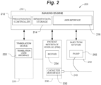
- FIG. 2 is a block diagram illustrating exemplary system 200 adapted to perform intravascular imaging.
- System 200 can include PIM 230, translation device 220, injection system 250, catheter assembly 240, and imaging engine 210.
- System 200 can be configured to be used with an OCT and/or an IVUS based intravascular imaging device.
- PIM 230 can provide an electromechanical interface between catheter assembly 240 and imaging engine 210.
- PIM 230 may provide a catheter interface 232 to secure catheter assembly 240 to system 200.
- the PIM 230 may include a motor 234 configured to provide mechanical energy to rotate an intravascular imaging device (e.g., ultrasound transducer) of catheter assembly 240.
- PIM 230 may provide an electrical interface that transmits signals from the intravascular imaging device of catheter assembly 240 and receives return signals.
- Translation device 220 can be configured to provide longitudinal translation of catheter assembly 240.
- Translation device 220 may comprise a Linear Translation System (LTS).
- LTS Linear Translation System
- the translation device 220 may be configured to mate with PIM 230 and catheter assembly 240 to enable controlled pullback of an intravascular imaging device of catheter assembly 240.
- translation device 220 may feature a translation user interface 222 which may comprise a translation display configured to display translation data associated with the translation of the intravascular imaging device to a user of system 200.
- translation data may include linear distance traversed and/or translation speed.
- the translation user interface 222 may be configured to receive inputs from a user to control starting/stopping translation, setting translation speed, resetting linear distance traversed to zero, and/or switching to manual mode.
- a user may freely move the intravascular imaging device of the catheter assembly forward and backward (e.g., distally and proximally within a vessel).
- the translation device 220 may be configured to enable both pullback and push-forward of the intravascular imaging device at a controlled rate.
- the translation device 220 may be configured to oscillate, or cycle, the intravascular imaging device by alternately performing pullback and push-forward operations.
- translation device 220 may include a position sensor configured to measure a distance of a translation operation.
- the injection system 250 can be configured to deliver fluid into a vessel of a patient via catheter assembly 240. Although, in some embodiments the system 200 may not include the injection system 250.
- Injection system 250 when present in the system 200, may comprise an injector pump 252 configured to deliver one or more fluids (e.g., contrast or saline) into the patient.
- the injector pump 252 may be automated, in electrical communication with, and controlled by imaging engine 210.
- injector pump 252 may comprise a manual pump (e.g., syringe injection) configured to allow a user to manually deliver one or more fluids into the patient.
- the injection system 250 may be in fluid communication with an intravascular blood displacement fluid port, which may be associated with catheter assembly 240, such that fluid from the injection system 250 is delivered into a patient's vasculature via the intravascular blood displacement fluid port.
- the injection system 250 may be configured to deliver any number of fluids and any quantity of fluid as appropriate for a specific application of system 200.
- the quantity of blood displacement fluid may comprise a contrast media or saline.
- the imaging engine 210 includes one or more programmable processors 212, memory/data storage component 214 which can be in communication with the one or more programmable processors 212, and a user interface 216 which can be in communication with the one or more programmable processors 212 and/or the memory/storage component 214.
- the imaging engine 210 can itself be in communication with the translation device 220, PIM 230, and/or injection system 250 (when present).
- the user interface 216 can include a display for outputting an image generated based on image data acquired by the catheter assembly 240 (e.g., an ultrasound transducer of the catheter assembly).
- image data acquired by the catheter assembly 240 can undergo one or more processing techniques at the imaging engine 210.
- the memory/data storage component 214 can include instructions, or software, for performing one or more processing techniques and the one or more processors 212 may execute the processing techniques based on the instructions.
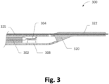
- FIG. 3 shows an exemplary side cross-sectional view of an embodiment of a distal portion of a catheter assembly 300, which can be used in the systems described previously with respect to FIGS. 1 and 2 .
- the catheter assembly 300 may include a drive cable 302, a sheath 308, and an ultrasound transducer 304.
- the drive cable may be coupled to a PIM to rotate the drive cable 302 within sheath 308.
- the ultrasound transducer 304 may be coupled to the drive cable such that the rotation and/or translation of the drive cable causes ultrasound transducer 304 to rotate and/or translate within sheath 308.
- the ultrasound transducer 304 may be configured to emit and receive acoustic energy during rotation and/or translation to generate ultrasound data.
- the catheter assembly 300 may also include an imaging window (not shown) substantially transparent to the frequency of the acoustic energy emitted by the ultrasound transducer.
- the catheter assembly 300 may also include a distal end 320 forming a guidewire lumen 322 configured to accept a guidewire 325 to guide the catheter assembly 300 into a vessel of a patient and/or translate the catheter assembly 300 within the vessel.
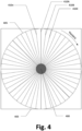
- FIG. 4 illustrates an exemplary front view of propagating ultrasound data vectors of a catheter 400.
- the catheter 400 may be a mechanically rotating ultrasound imaging catheter similar to catheters previously described.
- the catheter 400 may be configured to rotate an ultrasound transducer (not shown) relative to a sheath of catheter 400, and the ultrasound transducer may be configured to generate ultrasound data by emitting and receiving acoustic energy.
- the ultrasound data vectors illustrated in FIG. 4 are indicative of acoustic energy emitted and received by the ultrasound transducer at different rotational positions. More specifically, each data vector is representative of ultrasound data collected by the ultrasound transducer at different rotational positions of the ultrasound transducer.
- the ultrasound transducer of catheter 400 may generate ultrasound data on a vector-by-vector basis as the transducer is rotated.
- the ultrasound transducer may initially acquire an ultrasound data vector 410A and continue to acquire vectors 410B through 410n as the ultrasound transducer is rotated clockwise.
- vectors 410A-410n can be representative of a full 360 degree rotation of the ultrasound transducer.
- the transducer can, in some instances, rotate and acquire the data vectors at a constant longitudinal position within the vessel, or, in other instances, rotate and acquire the data vectors simultaneous to longitudinal translation within the vessel.
- the number of data vectors acquired per rotation may vary depending on the application of the catheter.
- the IVUS catheter is configured to generate between about 500 and about 5000 vectors per rotation.
- the angle between data vectors may then be characterized as approximately 2 ⁇ /512 radians or 360/512 degrees.
- the angle between data vectors may be approximately 2 ⁇ /4096 or 360/4096 degrees.
- FIG. 4 also provides a representation of an image data frame 403 that comprises vectors 410A-410n.
- Data frame 403 includes vectors emitted and received over a first period of time, and thus includes image data generated at the first period of time.
- rotation of the transducer can occur at a rate that results in the image data of the data frame 403 being generated at substantially the same time.
- a field of view 405 of the catheter 400 may be based on the magnitude of the data vectors propagated by the catheter and may vary to suit a specific application. The magnitude of the data vectors may be based on a number of factors, for example, the frequency of the emitted wave and/or the power level of the wave.
- the ultrasound transducer of catheter 400 can emit acoustic energy at one or more frequencies.
- the ultrasound transducer can emit acoustic energy at a frequency of approximately 60 MHz.
- the ultrasound transducer can emit acoustic energy at a frequency of approximately 40 MHz.
- Image data generated at a low frequency e.g., equal to or less than 40Mhz
- image data acquired at a high frequency e.g., greater than 40MHz, such as 60 MHz
- the frequency at which the transducer emits energy and acquires data vectors may vary depending on the particular application.
- the transducer can emit and acquire data vectors at more than one frequency, whether the data vectors alternate in frequency sequentially or non-sequentially during a single rotation of the transducer.
- FIG. 5 is a cross-sectional view showing a catheter 510 within a vessel 550.
- catheter 510 may be directly guided into the vessel or, in certain examples, be guided into the vessel via a guide wire.
- the catheter 510 via the imaging device and imaging module thereof (e.g., ultrasound transducer) can emit and receive energy. This can be, in some examples, in the form of a plurality of data vectors acquired during rotation of the imaging module, such as shown in FIG. 4 .
- the catheter 510 can thereby generate cross-sectional image data.
- the vessel 550 may be a vessel of a vascular system of a patient including a vessel wall 554 defining a vessel lumen 552 through which blood flows.
- the vessel lumen 552 may also include, in various applications, one or more plaque components that have accumulated within the vessel lumen 552 over time, such as at the interface of the vessel wall 554 and the vessel lumen 552.
- plaque components can include, for instance, atherosclerotic plaque such as lipids.
- the image generated using the image data collected by the catheter 510 can allow a user to visually discern certain structures of the vessel 550 more easily than other structures.
- the generated image may visually present to a user a relatively identifiable external elastic membrane boundary of the vessel 550.
- the interface between blood within the lumen 552 and plaque along an inner surface of the vessel wall 554 is an important item to discern in the generated image for diagnostic purposes.
- Exemplary embodiments are described herein for indicating various structures, and/or boundaries between such structures, that may otherwise be difficult to visually discern from a generated image.
- the described exemplary embodiments can utilize differential movement of items of a vessel over time to distinguish between, and identify, such structures.
- One such example includes differential movement over time (e.g., over portions of a cardiac cycle) of blood versus tissue and plaque.
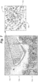
- FIG. 6 shows an exemplary schematic diagram illustrating comparison of a first image data frame 602 and a second image data frame 604.
- the image data frames 602, 604 can, in some examples, be generated using a system similar to any of those described previously, including an intravascular ultrasound imaging system.
- cross-sectional image data may be collected using a catheter assembly having an intravascular imaging device including an imaging module for emitting and receiving energy also similar to that described previously.
- the image data frames 602, 604 can each include image data representing a plurality of items in an imaging view of the imaging module (e.g., an ultrasound transducer).
- the image data can represent various items within the vessel at the location where the imaging module collected the data.
- the image data can represent structures of and within the vessel, including blood, plaque, stent location, various lesions, lumen geometry, and vessel wall structures (e.g. vessel wall layers and interfaces therebetween).
- the first image data frame 602 and the second image data frame 604 can be generated at first and second times that are different.
- the first image data frame 602 can represent image data collected during a first rotation (e.g., full 360 degree rotation) of the imaging module
- the second image data frame 604 can represent image data collected during a second, previous or subsequent rotation (e.g., full 360 degree rotation) of the imaging module.
- the first data frame 602 can be taken at a first time at a first longitudinal location within the vessel
- the second data frame 604 can be taken at a second different time at a second different longitudinal location within the vessel (e.g., as by translating the imaging module within the vessel as described previously).
- the image data frames 602, 604 can be adjacent (e.g., neighboring) frames generated consecutively within the vessel (whether the first data frame 602 is collected previous to or subsequent to the second data frame 604). But, in other cases, the image data frames 602, 604 can be spaced apart by other data frames generated in between the data frames 602, 604 (e.g., spaced apart by one, two, three, five, ten, or more data frames).
- the different respective times at which the first and second image data frames 602, 604 are collected can vary, for instance, according to a particular imaging application.
- the first and second data frames 602, 604 can be generated respectively at different parts of a patient's cardiac cycle (e.g., one frame at the diastole stage and one frame at the systole stage, whether both are of a same single cycle or each is from a different cycle).
- the first image data frame 602 can be generated at a first time corresponding to a first part of a patient's cardiac cycle while the second image data frame 604 can be generated at a second time corresponding to a second, different part of the patient's cardiac cycle.
- a patient's heart rate can be measured and used as an input in the imaging system (e.g., intravascular ultrasound imaging system described previously).
- the measured heart rate can provide a user with information as to the frequency of the cardiac cycle.
- the first time at which the first image data frame 602 is generated and the second different time at which the second image data frame 604 is generated can be determined by using the measured heart rate of the patient.
- the imaging system can use the input of the patient's measured heart rate to automatically control the imaging module to generate image data frames 602, 604 at different parts of the patient's cardiac cycle.
- the first image data frame 602 can be divided up into multiple portions that each have a subset of all image data of the first image data frame 602. In some cases this can be accomplished by first converting the generated image data from a Cartesian coordinate into a Polar coordinate form, but in other cases any form of the image data represented in the image data frames can be used. As shown in the example of FIG. 6 , the first image data frame 602 is subdivided up into a number of portions 606 each having a subset of the image data of the first image data frame 602. As shown in the illustrated example here, the first image data frame 602 is subdivided up into a 7x7 series of image blocks.
- any number of portions 606 can be used (e.g., 2x2, 16x16, etc. series of image blocks) to cover the whole image frame or one or more portions of the image frame.
- the shape of each the portions 606 can take a variety of shapes (e.g., square, rectangular, circular, elliptical, etc., or even free-form) of various sizes.
- the number of portions 606 into which the first image data frame 602 can be divided up may depend, for example, on the accuracy desired and/or processing capability available for a particular application.
- a particular portion 606 of the first image data frame 602 can be selected and compared to the image data of the second image data frame 604. This comparison can serve to locate image data within the second image data frame 604 that corresponds to the image data represented by the particular portion 606 of the first image data frame 602. This could include, in some cases, determining where the specific item (e.g., vessel structure), or portion of the structure, represented by the particular portion 606 is present within the image data of the second image data frame 604.
- a variety of techniques can be used to locate image data within the second image data frame 604 that corresponds to the image data represented by the particular portion 606 of the first image data frame 602.
- the selected particular portion 606 of the first image data frame 602 can be compared to image data of the second image data frame 604 to select a portion 608 of the second image data frame 604.
- the portion 608 of the second image data frame 604 can constitute a subset of all image data of the second image data frame 604.
- the portion 608 of the second image data frame 604 can be selected based on the comparison by determining that the subset of image data represented by the portion 608 corresponds to the subset of image data represented by the particular portion 606.
- the image data represented by the particular portion 606 of the first image data frame 602 can be compared to image data represented in each of multiple portions of the second image data frame 604.
- the portion 608 of the second image data frame 604 can then be selected from the multiple portions of the second image data frame 604.
- the portion 608 can be selected by determining that the portion 608 corresponds to the image data represented by the selected particular portion 606 to a greater degree than image data of any other portion of the second image data frame 604.
- the comparison may include calculating a matching error between the image data of the selected particular portion 606 and the image data of each of the multiple portions of the second image data frame 604.
- the calculated matching error can be a numerical representation of the similarity of the image data in the compared portions (e.g., a summation of all error calculated between the image data of the compared portions).
- the portion 608 can be selected as the portion of the second image data frame 604 that has the lowest matching error with the image data of the particular portion 606.
- the particular portion 606 can be compared to all image data of the second image data frame 604.
- the multiple portions into which the second image data frame 604 is divided would include all image data of the second image data frame 604.
- the particular portion 606 would be compared, as described previously, to all image data of the second image data frame 604 and the portion 608 accordingly selected from all image data of the second image data frame 604.
- the particular portion 606 can be compared to only a subset of all image data of the second image data fame 604.
- the particular portion 606 can be compared only to image data of the second image data frame 604 that is within a search window 610 of the second image data frame 604 (e.g., each of the multiple portions of the second image data frame 604 to which the particular portion 606 is compared are within the search window 610).
- the search window 610 constitutes less than all image data of the second image data frame 604, and thus defines a subset of all image data of the second image data frame 604.
- the size of the search window 610 can vary in different embodiments such as from a size that is just larger than the particular portion 606 (e.g., includes slightly more image data than the particular portion 606) to a size that is just less than the entirety of the second image data frame 604.
- the search window 610 is larger than the particular portion 606 and constitutes a subset of all image data of the second image data frame 604 that excludes image data forming a perimeter of the second image data frame 604. It may be useful to exclude from the comparison with the particular portion 606 image data at one or more locations of the second image data frame 604 which are known to be unlikely to include image data corresponding to the image data of the particular portion 606.
- intravascular imaging where the interface between blood within the vessel lumen and plaque along the vessel wall is to be identified, it may be useful for efficiency purposes in some cases to exclude the perimeter of frame 604 from the comparison to the particular portion 606.
- the particular portion 606 of the first image data frame 602 can be compared only to each portion of the second image data frame 604 within the defined search window 610.
- the portion 608 of the second image data frame 604 can be selected from the search window 610 by determining that the image data represented by the particular portion 606 corresponds to the image data represented by the portion 608 to a greater degree than image data at any other portion of the search window 610. In one instance, this could be determined by the portion 608 having the lowest calculated matching error with the image data represented by the particular portion 606 of all portions within the search window 610.
- the second frame 604 can serve as a reference frame for more than one frame 602 in selecting the portion 608.
- the more than one frame 602 can include one or more frames generated prior to the frame 604 and/or one or more frames generated subsequent to the frame 604.
- the particular portion 606 can be selected in each of two or more frames 602, where the particular portion 606 in each of the frames 602 is selected as corresponding to the same image data.
- a corresponding portion 608 can be selected in a similar manner as that described above for each of the particular portions 606 in each of the frames 602.
- a weighted average across each of the selected portions 608 in the frame 604 can be used to determine a composite portion in the frame 604, and this composite portion can be used similar to that described further below for the portion 608.
- a displacement vector 612 can be calculated.
- the location of the image data represented by the portion 606 is shown as simulated onto the second image data frame 604 as portion 606'.
- the displacement vector 612 can represent relative movement between the image data represented in portions 606 and 608. Where the first and second frames 602 and 604 are generated at different times, the displacement vector 612 can represent movement between the image data represented in portions 606 and 608 over the period of time between generation of the image data frames 602 and 604. Since the portion 608 may be selected as encompassing image data corresponding to image data represented by the portion 606, the displacement vector 612 can serve to represent movement of the same item represented by the image data of the portions 606, 608 over this period of time. Specifically, a length of the displacement vector 612 can be used as a measure of the extent of movement of the item over the period of time between the first and second data frames 602, 604. In the described example, the longer the displacement vector, the greater the degree of movement of the object over the period of time. The degree of movement of the object over the period of time can then be used to determine the identity of the object, allowing such object to be indicated in a generated image.
- each such displacement vector can represent relative movement between the image data in the respective portion of the first image data frame 602 and the corresponding image data in the respective portion of the second image data frame 604 over the period of time between the first and second data frames 602, 604.
- the length of each such displacement vector can be stored in memory or otherwise noted. As will be described further below, the relative difference in length of the calculated displacement vectors can be used to identify differential movement over the period of time.
- FIG. 7 shows an exemplary diagram illustrating a number of displacement vectors 702 each calculated using the comparisons described previously with respect to FIG. 6 .
- each displacement vector 702 can serve to represent relative movement over time of corresponding image data of portions of first and second frames (e.g., relative movement of an object in an imaging view over time).
- relative lengths of two or more displacement vectors 702 can be compared, for instance, to distinguish objects in an imaging view. For example, determining that two displacement vectors have differing lengths (or have lengths differing beyond a predetermined degree) can indicate that the image data represented by each moved to differing degrees over the period of time. In some cases, differing degrees of movement of such image data can signify that the respective image data corresponds to different objects in an imaging view.
- objects in an imaging view can include blood, plaque, and vessel tissue. The movement of blood over time may be distinct from the movement of tissue, and plaque built-up at the tissue, over the same time (e.g., over one or more particular portions of a cardiac cycle). Therefore, in this application, comparing lengths of displacement vectors may allow for a determination as to whether the image data represents blood or rather represents either tissue or plaque.
- regions 704 are defined by the presence of displacement vectors 702 having a length equal to or greater than a predetermined length
- regions 706 are defined by the presence of displacement vectors 702 having a length less than the predetermined length.
- These lengths may signify that image data in regions 704 moved to a similar degree over the period of time, and further that image data in regions 706 moved to a similar degree over the period of time different from that of the regions 704.
- the relative lengths of displacement vectors have been discussed herein as useful for distinguishing items in an imaging view based on the extent of movement over time of the item(s), other characteristics of the calculated displacement vectors can be used in addition to, or as an alternative to, the length of the displacement vectors.
- the direction of the displacement vectors and therefore the direction in which the image data representing the item has moved over time, can be used to distinguish items in the imaging view.
- using the direction of the displacement vectors can further include using a slope of the displacement vectors in the particular direction to distinguish items in the imaging view.
- the indicator can be included on a displayed image at a location on the image that is determined using the length and direction of displacement vectors calculated in the manner described previously.
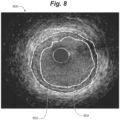
- FIG. 8 shows an exemplary vessel cross-sectional image 800 output with indicators 802 and 804 thereon.
- the indicator 802 represents an external elastic membrane boundary of the imaged vessel
- the indicator 804 represents an interface between a vessel lumen and plaque (e.g., accumulated along a vessel wall).
- One or both of the indictors 802, 804 can be located on the image 800 using the one or more of the calculated displacement vectors.
- the indicator 804 can be located on the image 800 by comparing two or more of the calculated displacement vectors. A location where the two or more data vectors differ beyond a predetermined degree (e.g., where the lengths of the two or more data vectors differ beyond a predetermined degree) can be used as a location for the indicator 804.
- the indicator 804 is positioned on the output image 800 in one embodiment at a location on the image 800 that is a function of displacement vectors at the location differing in relative length beyond a predetermined degree.
- the indicators 802, 804 in the example of FIG. 8 are in the form of solid lines of differing colors, and represent a boundary between items in the imaged vessel.
- one or more indicators can be included on the generated image in various forms.
- an indicator could take the form of a shaded region on the image 800 representing a particular item of the vessel at the shaded region.
- an indicator could take the form of an arrow directed to a specific location on the image 800 representing a particular item, or portion of an item (e.g., a portion that is abnormal to the remainder of the item), of the vessel at the location of the arrow.
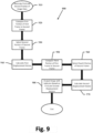
- FIG. 9 shows a flow diagram of an embodiment of a method 900 for segmenting an image.
- the method 900 includes generating first and second frames of image data (step 910). This step can include acquiring a plurality of data vectors at a first time to form a first frame of image data, and acquiring a plurality of data vectors at a second, different time to form the second frame of image data.
- Data vectors can be acquired in some examples using an intravascular imaging system having an intravascular imaging device (e.g., ultrasound transducer) for emitting and receiving acoustic energy at the imaging device similar to that described previously.
- an intravascular imaging device e.g., ultrasound transducer
- the embodiment of the method 900 further includes selecting a first portion of the first frame having a subset of the image data of the first frame, and comparing the first portion to image data of the second frame (step 920).
- this step can include comparing the first portion to all image data of the second frame.
- this step can include comparing the first portion to a subset of the image data of the second frame, such as comparing the first portion only to image data within a search window of the second frame.
- the embodiment of the method 900 also includes selecting a second portion having a subset of image data of the second frame based on the comparison of the first portion of the first frame to image data of the second frame (step 930).
- the second portion of the second frame can be selected based on the comparison by determining that the subset of image data represented by the second portion corresponds to the subset of image data represented by the first portion.
- the image data of the second portion may correspond to the image data of the first portion where the image data of the second portion corresponds to the image data of the first portion to a greater degree than image data of any other portion of the second frame.
- the second portion can be selected as the portion of the second frame that has a lowest numerical matching error with the image data represented by the first portion.
- the method 900 additionally includes calculation of a first displacement vector (step 940).
- the first displacement vector e.g., a length of the first displacement vector
- the first displacement vector can represent relative movement between the selected first portion and the selected second portion over a period of time between the generation of the first and second frames. Therefore, the first displacement vector can represent relative movement of the image data represented by the corresponding first and second portions of the respective first and second frames over the period of time.
- the embodiment of the method 900 further includes selecting a third portion of the first frame having a subset of the image data of the first frame, and comparing the third portion to image data of the second frame (step 950).
- the third portion of the first frame can be a different portion than the first portion of the first frame, and thus may represent different image data of the first frame than the first portion. This step can be similar to the comparison of the first portion to image data of the second frame as described previously.
- a fourth portion having a subset of image data of the second frame is selected based on the comparison of the third portion of the first frame to image data of the second frame (step 960). This step can be similar to the selection of the second portion of the second frame as described previously.
- the method 900 additionally includes calculation of a second displacement vector (step 970).
- the second displacement vector e.g., a length of the second displacement vector
- the second displacement vector can represent relative movement between the selected third portion and the selected fourth portion over a period of time between the generation of the first and second frames. Therefore, the second displacement vector can represent relative movement of the image data represented by the corresponding third and fourth portions of the respective first and second frames over the period of time.
- the embodiment of the method 900 may further include outputting an image with an indicator thereon, where the location of the indicator on the image is determined by using the calculated first and second displacement vectors (step 980).
- This step may include comparing the first and second displacement vectors, such as comparing a length of the first displacement vector to a length of the second displacement vector. It may be determined that respective image data of the first and third portions of the first frame represents differing items in an imaging view where the length of first displacement vector differs from the length of the second displacement vector beyond a predetermined degree.
- an image can be output with an indicator showing the different items in the imaging view.
- the indicator can show an interface between different items in the imaging view.
- the generated image with the indicator may be useful in diagnostic procedures where a geometry of a vessel plays a role in the diagnosis and the determination for a need to take interventional actions with respect to the vessel.
- Embodiments also include systems that perform the described method.
- a further embodiment can include an imaging system.
- the system may include a catheter assembly with an intravascular imaging device (e.g., including an ultrasound transducer) to generate imaging data.
- the image data generated by the catheter assembly can represent a plurality of image elements.
- the system may also include a user interface having an image display region.
- the user interface can be configured to receive inputs from a user, and may include, at least in part, one or more touchscreens.
- the system can further include an imaging engine in communication with the intravascular imaging device and the user interface.
- the imaging engine may have at least one processor that can be used in segmenting an image to be displayed on the user interface.
- the imaging engine can be configured to receive a plurality of data vectors forming a first frame of image data and a plurality of data vectors forming a second frame of image data.
- the respective data vectors forming the first frame can be taken over a first period of time
- the plurality of data vectors forming the second frame can be taken over a second period of time different from the first period of time (e.g., previous to or subsequent to the first period of time).
- a patient's heart rate can be used as an input to the imaging engine for generating the first and second frames at desired portions a patient's cardiac cycle.
- the imaging engine can compare a portion of the first frame to image data of the second frame. Based on the comparison, using the at least one processor the imaging engine can select a portion of the image data of the second frame corresponding to the portion of the first frame. A displacement vector representing movement over the period of time of the corresponding image data in the portions of the first and second frames can then be calculated by the imaging engine using the at least one processor. This process can be repeated to calculate a number of displacement vectors for different portions of the image data.
- the imaging engine, using the at least one processor can compare the displacement vectors to identify differential movement of items represented by the image data. This can include the at least one processor comparing relative lengths of the displacement vectors. Finally, the at least one processor can determine a location on the displayed image for an indicator using the comparison of the displacement vectors.
- Another embodiment can include a non-transitory computer-readable storage article having computer-executable instructions sorted thereon to cause at least one programmable processor to display an image having an indicator for one or more items in the imaging view.
- the at least one programmable processor may receive a plurality of data vectors forming first and second data frames corresponding to different times.
- the at least one programmable processor can compare a portion of the first frame to image data of the second frame. Based on the comparison, the at least one programmable processor can select a portion of the image data of the second frame corresponding to the image data of the portion of the first frame.
- a displacement vector representing movement over the period of time of the corresponding image data in the portions of the first and second frames can then be calculated by the at least one programmable processor.
- the at least one programmable processor can compare the displacement vectors to identify differential movement of items represented by the image data. This can include the at least one programmable processor comparing relative lengths of the displacement vectors. Finally, the at least one programmable processor can determine a location on the displayed image for an indicator using the comparison of the displacement vectors.
Landscapes
- Engineering & Computer Science (AREA)
- Health & Medical Sciences (AREA)
- Physics & Mathematics (AREA)
- Life Sciences & Earth Sciences (AREA)
- Medical Informatics (AREA)
- General Health & Medical Sciences (AREA)
- Public Health (AREA)
- Theoretical Computer Science (AREA)
- General Physics & Mathematics (AREA)
- Computer Vision & Pattern Recognition (AREA)
- Multimedia (AREA)
- Primary Health Care (AREA)
- Epidemiology (AREA)
- Nuclear Medicine, Radiotherapy & Molecular Imaging (AREA)
- Radiology & Medical Imaging (AREA)
- Animal Behavior & Ethology (AREA)
- Biophysics (AREA)
- Molecular Biology (AREA)
- Heart & Thoracic Surgery (AREA)
- Biomedical Technology (AREA)
- Veterinary Medicine (AREA)
- Surgery (AREA)
- Pathology (AREA)
- Physiology (AREA)
- Cardiology (AREA)
- Vascular Medicine (AREA)
- Chemical & Material Sciences (AREA)
- Bioinformatics & Cheminformatics (AREA)
- Medicinal Chemistry (AREA)
- Ultra Sonic Daignosis Equipment (AREA)
- Endoscopes (AREA)
Applications Claiming Priority (2)
| Application Number | Priority Date | Filing Date | Title |
|---|---|---|---|
| US201662336903P | 2016-05-16 | 2016-05-16 | |
| PCT/US2017/032592 WO2017200899A1 (en) | 2016-05-16 | 2017-05-15 | Motion-based image segmentation systems and methods |
Publications (2)
| Publication Number | Publication Date |
|---|---|
| EP3459048A1 EP3459048A1 (en) | 2019-03-27 |
| EP3459048B1 true EP3459048B1 (en) | 2023-05-03 |
Family
ID=58765996
Family Applications (1)
| Application Number | Title | Priority Date | Filing Date |
|---|---|---|---|
| EP17725483.6A Active EP3459048B1 (en) | 2016-05-16 | 2017-05-15 | Motion-based image segmentation systems and methods |
Country Status (5)
| Country | Link |
|---|---|
| US (1) | US10489919B2 (enExample) |
| EP (1) | EP3459048B1 (enExample) |
| JP (1) | JP7152955B2 (enExample) |
| CN (1) | CN109478332B (enExample) |
| WO (1) | WO2017200899A1 (enExample) |
Families Citing this family (10)
| Publication number | Priority date | Publication date | Assignee | Title |
|---|---|---|---|---|
| EP2488107B1 (en) | 2009-10-12 | 2017-03-08 | Acist Medical Systems, Inc. | Intravascular ultrasound system for co-registered imaging |
| EP3055709B1 (en) | 2013-10-07 | 2018-12-26 | Acist Medical Systems, Inc. | Signal processing for intravascular imaging |
| US10909661B2 (en) | 2015-10-08 | 2021-02-02 | Acist Medical Systems, Inc. | Systems and methods to reduce near-field artifacts |
| US10653393B2 (en) | 2015-10-08 | 2020-05-19 | Acist Medical Systems, Inc. | Intravascular ultrasound imaging with frequency selective imaging methods and systems |
| US10083372B2 (en) * | 2015-11-03 | 2018-09-25 | Toshiba Medical Systems Corporation | Ultrasound diagnosis apparatus, image processing apparatus and image processing method |
| US11369337B2 (en) | 2015-12-11 | 2022-06-28 | Acist Medical Systems, Inc. | Detection of disturbed blood flow |
| WO2017117389A1 (en) | 2015-12-31 | 2017-07-06 | Acist Medical Systems, Inc. | Semi-automated image segmentation system and method |
| CN109766953B (zh) * | 2019-01-22 | 2021-07-13 | 中国人民公安大学 | 对象识别方法及装置 |
| US11024034B2 (en) * | 2019-07-02 | 2021-06-01 | Acist Medical Systems, Inc. | Image segmentation confidence determination |
| CN115944389B (zh) * | 2023-03-14 | 2023-05-23 | 杭州脉流科技有限公司 | 弹簧圈模拟植入的方法和计算机设备 |
Family Cites Families (110)
| Publication number | Priority date | Publication date | Assignee | Title |
|---|---|---|---|---|
| JPS5519392B2 (enExample) | 1973-07-25 | 1980-05-26 | ||
| US4347443A (en) | 1981-06-18 | 1982-08-31 | Honeywell Inc. | Room thermostat with electronic circuit board heat removal air wash |
| JPS62221335A (ja) | 1986-03-20 | 1987-09-29 | 株式会社島津製作所 | 血流速度変化曲線表示システム |
| DE3727213A1 (de) | 1986-08-14 | 1988-02-18 | Olympus Optical Co | Ultraschall-diagnosevorrichtung |
| JPH074373B2 (ja) | 1986-10-16 | 1995-01-25 | オリンパス光学工業株式会社 | 超音波内視鏡装置 |
| US5070734A (en) | 1988-06-15 | 1991-12-10 | Matsushita Electric Industrial Co., Ltd. | Ultrasonic diagnostic apparatus |
| US4949310A (en) | 1988-11-21 | 1990-08-14 | Duke University | Maltese cross processor: a high speed compound acoustic imaging system |
| DE58905475D1 (de) | 1989-05-30 | 1993-10-07 | Siemens Ag | Drucksensor und Verfahren zu seiner Herstellung. |
| JPH0744931B2 (ja) | 1990-06-25 | 1995-05-17 | 富士写真光機株式会社 | 超音波検査装置 |
| WO1992011055A1 (en) | 1990-12-17 | 1992-07-09 | Cardiovascular Imaging Systems, Inc. | Vascular catheter having low-profile distal end |
| US5183048A (en) | 1991-06-24 | 1993-02-02 | Endosonics Corporation | Method and apparatus for removing artifacts from an ultrasonically generated image of a small cavity |
| US5396285A (en) | 1993-05-07 | 1995-03-07 | Acuson Corporation | Ultrasound imaging method and apparatus with dynamic non-linear filtering |
| US5363849A (en) | 1994-01-26 | 1994-11-15 | Cardiovascular Imaging Systems, Inc. | Enhancing intravascular ultrasonic blood vessel image |
| US5531679A (en) | 1994-03-14 | 1996-07-02 | Schulman; Joseph H. | Fluidic infusion system for catheter or probe |
| US5462057A (en) | 1994-06-06 | 1995-10-31 | Hewlett-Packard Company | Ultrasound imaging system using line splicing and parallel receive beam formation |
| US7110587B1 (en) | 1995-05-31 | 2006-09-19 | Ge Medical Systems Israel Ltd. | Registration of nuclear medicine images |
| JPH09522A (ja) | 1995-06-23 | 1997-01-07 | Toshiba Corp | 超音波プローブ及び超音波診断装置 |
| US5741552A (en) | 1995-06-27 | 1998-04-21 | Nippon Paint Co., Ltd. | Coating composition and method for forming multi-layer coating |
| US5690115A (en) | 1995-09-21 | 1997-11-25 | Feldman; Charles L. | Detecting vascular stenosis in chronic hemodialysis patients |
| ES2235180T3 (es) | 1995-10-10 | 2005-07-01 | Advanced Technology Laboratories, Inc. | Formacion de imagenes de diagnostico por ultrasonidos con agentes de contraste. |
| US6215910B1 (en) | 1996-03-28 | 2001-04-10 | Microsoft Corporation | Table-based compression with embedded coding |
| US5848969A (en) | 1996-10-28 | 1998-12-15 | Ep Technologies, Inc. | Systems and methods for visualizing interior tissue regions using expandable imaging structures |
| EP0851241B1 (en) | 1996-11-26 | 2006-05-24 | ATL Ultrasound, Inc. | Ultrasonic diagnostic imaging of response frequency differing from transmit frequency |
| US5919137A (en) | 1996-12-04 | 1999-07-06 | Acuson Corporation | Ultrasonic diagnostic imaging system with programmable acoustic signal processor |
| US20010017941A1 (en) | 1997-03-14 | 2001-08-30 | Navin Chaddha | Method and apparatus for table-based compression with embedded coding |
| US5921931A (en) | 1997-04-08 | 1999-07-13 | Endosonics Corporation | Method and apparatus for creating a color blood flow image based upon ultrasonic echo signals received by an intravascular ultrasound imaging probe |
| US5833615A (en) | 1997-05-09 | 1998-11-10 | Thomas Jefferson University | Excitation enhanced ultrasound system |
| US6132374A (en) | 1997-08-01 | 2000-10-17 | Acuson Corporation | Ultrasonic imaging method and system |
| US5876343A (en) | 1997-09-23 | 1999-03-02 | Scimed Life Systems, Inc. | Methods and apparatus for blood speckle detection in an intravascular ultrasound imaging system |
| US6036650A (en) | 1998-09-15 | 2000-03-14 | Endosonics Corporation | Ultrasonic imaging system and method with ringdown reduction |
| US6102862A (en) | 1998-10-02 | 2000-08-15 | Scimed Life Systems, Inc. | Adaptive cancellation of ring-down artifact in IVUS imaging |
| US6645147B1 (en) | 1998-11-25 | 2003-11-11 | Acuson Corporation | Diagnostic medical ultrasound image and system for contrast agent imaging |
| US7194294B2 (en) | 1999-01-06 | 2007-03-20 | Scimed Life Systems, Inc. | Multi-functional medical catheter and methods of use |
| US6216025B1 (en) | 1999-02-02 | 2001-04-10 | Optosonics, Inc. | Thermoacoustic computed tomography scanner |
| US6139501A (en) | 1999-06-08 | 2000-10-31 | Atl Ultrasound, Inc. | Coincident tissue and motion ultrasonic diagnostic imaging |
| US6381350B1 (en) | 1999-07-02 | 2002-04-30 | The Cleveland Clinic Foundation | Intravascular ultrasonic analysis using active contour method and system |
| US6896658B2 (en) | 2001-10-20 | 2005-05-24 | Zonare Medical Systems, Inc. | Simultaneous multi-mode and multi-band ultrasonic imaging |
| US6277075B1 (en) | 1999-11-26 | 2001-08-21 | Ge Medical Systems Global Technology Company, Llc | Method and apparatus for visualization of motion in ultrasound flow imaging using continuous data acquisition |
| US6454715B2 (en) | 2000-04-11 | 2002-09-24 | Scimed Life Systems, Inc. | Methods and apparatus for blood speckle detection in an intravascular ultrasound imaging system |
| JP2001333902A (ja) | 2000-05-25 | 2001-12-04 | Olympus Optical Co Ltd | 超音波診断装置 |
| US6590830B1 (en) | 2000-06-08 | 2003-07-08 | Advanced Imaging Technologies, Inc. | Apparatus and process modifications in ultrasonic holography to improve image quality |
| CA2312142A1 (en) | 2000-06-22 | 2001-12-22 | An-Go-Gen Inc. | Injection system for gene delivery |
| KR100722596B1 (ko) | 2001-04-19 | 2007-05-28 | 가부시끼가이샤 도시바 | 화상처리방법과 화상처리장치 |
| US6592523B2 (en) | 2001-11-21 | 2003-07-15 | Ge Medical Systems Global Technology Company, Llc | Computationally efficient noise reduction filter for enhancement of ultrasound images |
| US6704590B2 (en) | 2002-04-05 | 2004-03-09 | Cardiac Pacemakers, Inc. | Doppler guiding catheter using sensed blood turbulence levels |
| US6746401B2 (en) | 2002-05-06 | 2004-06-08 | Scimed Life Systems, Inc. | Tissue ablation visualization |
| US7396332B2 (en) | 2002-06-10 | 2008-07-08 | Scimed Life Systems, Inc. | Transducer with multiple resonant frequencies for an imaging catheter |
| JP3720797B2 (ja) * | 2002-08-26 | 2005-11-30 | 芳文 西條 | 超音波診断装置 |
| JP4226882B2 (ja) | 2002-11-29 | 2009-02-18 | 株式会社東芝 | 超音波診断装置 |
| US20050119573A1 (en) | 2003-11-05 | 2005-06-02 | Boris Vilenkin | Method and system for quantification of arterial stenosis |
| CA2449080A1 (en) | 2003-11-13 | 2005-05-13 | Centre Hospitalier De L'universite De Montreal - Chum | Apparatus and method for intravascular ultrasound image segmentation: a fast-marching method |
| JP4528529B2 (ja) | 2004-01-20 | 2010-08-18 | 株式会社東芝 | 超音波診断装置及び超音波画像データ処理方法 |
| CA2457171A1 (en) * | 2004-02-09 | 2005-08-09 | Centre Hospitalier De L'universite De Montreal - Chum | Imaging apparatus and methods |
| US7215802B2 (en) | 2004-03-04 | 2007-05-08 | The Cleveland Clinic Foundation | System and method for vascular border detection |
| US7397935B2 (en) | 2004-05-10 | 2008-07-08 | Mediguide Ltd. | Method for segmentation of IVUS image sequences |
| JP4648652B2 (ja) | 2004-06-24 | 2011-03-09 | テルモ株式会社 | 超音波診断装置および超音波診断装置の作動方法 |
| JP2006014938A (ja) | 2004-07-01 | 2006-01-19 | Shimadzu Corp | 超音波診断装置 |
| GB2417080B (en) | 2004-08-13 | 2008-05-21 | Stichting Tech Wetenschapp | Intravascular ultrasound techniques |
| US20080015569A1 (en) | 2005-02-02 | 2008-01-17 | Voyage Medical, Inc. | Methods and apparatus for treatment of atrial fibrillation |
| US20060253028A1 (en) | 2005-04-20 | 2006-11-09 | Scimed Life Systems, Inc. | Multiple transducer configurations for medical ultrasound imaging |
| ES2425388T3 (es) | 2005-05-06 | 2013-10-15 | Vasonova, Inc. | Aparato para el guiado y posicionamiento de un dispositivo endovascular |
| JP4691657B2 (ja) | 2005-07-28 | 2011-06-01 | 国立大学法人山口大学 | 柔軟な光ファイバーを関節内に挿入可能な関節内軟骨評価プローブ及び関節内軟骨評価装置 |
| US7831081B2 (en) | 2005-08-15 | 2010-11-09 | Boston Scientific Scimed, Inc. | Border detection in medical image analysis |
| US7801343B2 (en) | 2005-11-29 | 2010-09-21 | Siemens Medical Solutions Usa, Inc. | Method and apparatus for inner wall extraction and stent strut detection using intravascular optical coherence tomography imaging |
| US8012094B2 (en) | 2006-02-17 | 2011-09-06 | Esi, Inc. | Immersion bag system for use with an ultrasound probe |
| JP2007229015A (ja) | 2006-02-27 | 2007-09-13 | Fujifilm Corp | 超音波観測装置 |
| EP2076179B1 (en) | 2006-08-01 | 2018-07-04 | Stichting voor de Technische Wetenschappen | Pulse inversion sequences for nonlinear imaging |
| WO2008015586A2 (en) | 2006-08-02 | 2008-02-07 | Fotonation Vision Limited | Face recognition with combined pca-based datasets |
| US8060186B2 (en) | 2007-02-15 | 2011-11-15 | Siemens Aktiengesellschaft | System and method for intraoperative guidance of stent placement during endovascular interventions |
| WO2008110013A1 (en) | 2007-03-15 | 2008-09-18 | Centre Hospitalier De L'universite De Montreal | Image segmentation |
| US7789834B2 (en) | 2007-03-21 | 2010-09-07 | Volcano Corporation | Plaque characterization using multiple intravascular ultrasound datasets having distinct filter bands |
| EP3683768B1 (en) * | 2007-05-03 | 2023-06-28 | Sony Group Corporation | Method and system for initializing templates of moving objects |
| WO2009140534A2 (en) | 2008-05-15 | 2009-11-19 | Silicon Valley Medical Instruments, Inc. | Ivus system with rotary capacitive coupling |
| EP2143384A1 (en) | 2008-07-09 | 2010-01-13 | Medison Co., Ltd. | Enhanced ultrasound data processing in an ultrasound system |
| US7941774B2 (en) * | 2008-08-04 | 2011-05-10 | Texas Instruments Incorporated | Partial timing modeling for gate level simulation |
| EP2344020B1 (en) | 2008-10-14 | 2020-05-20 | Lightlab Imaging, Inc. | Stent strut detection and related measurement and display using optical coherence tomography |
| US8187191B2 (en) | 2009-01-08 | 2012-05-29 | Volcano Corporation | System and method for equalizing received intravascular ultrasound echo signals |
| JP5390942B2 (ja) | 2009-06-03 | 2014-01-15 | 富士フイルム株式会社 | 超音波診断装置及び信号処理プログラム |
| AU2010298333B2 (en) | 2009-09-23 | 2014-04-17 | Lightlab Imaging, Inc. | Lumen morphology and vascular resistance measurements data collection systems, apparatus and methods |
| EP2488107B1 (en) | 2009-10-12 | 2017-03-08 | Acist Medical Systems, Inc. | Intravascular ultrasound system for co-registered imaging |
| WO2011082171A1 (en) | 2009-12-29 | 2011-07-07 | Boston Scientific Scimed, Inc. | Systems and methods for multi-frequency imaging of patient tissue using intravascular ultrasound imaging systems |
| US20110257527A1 (en) | 2010-04-20 | 2011-10-20 | Suri Jasjit S | Ultrasound carotid media wall classification and imt measurement in curved vessels using recursive refinement and validation |
| JP5514911B2 (ja) | 2010-07-15 | 2014-06-04 | 株式会社日立メディコ | 超音波撮像装置 |
| CN103025247B (zh) * | 2010-08-31 | 2014-12-03 | 株式会社日立医疗器械 | 超声波诊断装置以及超声波图像显示方法 |
| WO2012034098A2 (en) | 2010-09-10 | 2012-03-15 | Silicon Valley Medical Instruments, Inc. | Apparatus and method for medical image searching |
| JP5209025B2 (ja) * | 2010-10-27 | 2013-06-12 | ジーイー・メディカル・システムズ・グローバル・テクノロジー・カンパニー・エルエルシー | 超音波診断装置 |
| US8591421B2 (en) | 2010-11-12 | 2013-11-26 | Boston Scientific Scimed, Inc. | Systems and methods for making and using rotational transducers for concurrently imaging blood flow and tissue |
| JP5756812B2 (ja) * | 2010-11-25 | 2015-07-29 | 株式会社日立メディコ | 超音波動画像処理方法、装置、およびプログラム |
| US8761469B2 (en) | 2011-01-03 | 2014-06-24 | Volcano Corporation | Artifact management in rotational imaging |
| CN103930037A (zh) | 2011-08-26 | 2014-07-16 | Ebm株式会社 | 血管治疗效果的血流模拟的系统、其方法及计算机软件程序 |
| EP2793703B1 (en) * | 2011-12-21 | 2020-07-15 | Volcano Corporation | Method for visualizing blood and blood-likelihood in vascular images |
| US10869648B2 (en) | 2012-05-11 | 2020-12-22 | Philips Image Guided Therapy Corporation | Device, system and method for flow imaging in the body using a swept transducer |
| CA2873391A1 (en) | 2012-05-11 | 2013-11-14 | Volcano Corporation | Device and system for imaging and blood flow velocity measurement |
| JP6251250B2 (ja) | 2012-05-25 | 2017-12-20 | アシスト・メディカル・システムズ,インコーポレイテッド | 流量計測システム及び方法 |
| US9324141B2 (en) | 2012-10-05 | 2016-04-26 | Volcano Corporation | Removal of A-scan streaking artifact |
| US11272845B2 (en) | 2012-10-05 | 2022-03-15 | Philips Image Guided Therapy Corporation | System and method for instant and automatic border detection |
| JP2014100249A (ja) * | 2012-11-19 | 2014-06-05 | Toshiba Corp | 血管解析装置、医用画像診断装置、血管解析方法、及び血管解析プログラム |
| JP6091870B2 (ja) * | 2012-12-07 | 2017-03-08 | 東芝メディカルシステムズ株式会社 | 血管解析装置、医用画像診断装置、血管解析方法、及び血管解析プログラム |
| US10398413B2 (en) | 2012-12-21 | 2019-09-03 | Volcano Corporation | Method for multi-frequency imaging and composite image display using high-bandwidth transducer outputs |
| US9173591B2 (en) | 2013-03-08 | 2015-11-03 | Lightlab Imaging, Inc. | Stent visualization and malapposition detection systems, devices, and methods |
| US10219887B2 (en) | 2013-03-14 | 2019-03-05 | Volcano Corporation | Filters with echogenic characteristics |
| US10245007B2 (en) | 2013-03-15 | 2019-04-02 | Infraredx, Inc. | High resolution intravascular ultrasound imaging systems and methods |
| US9702762B2 (en) | 2013-03-15 | 2017-07-11 | Lightlab Imaging, Inc. | Calibration and image processing devices, methods, and systems |
| US9693754B2 (en) | 2013-05-15 | 2017-07-04 | Acist Medical Systems, Inc. | Imaging processing systems and methods |
| EP3055709B1 (en) | 2013-10-07 | 2018-12-26 | Acist Medical Systems, Inc. | Signal processing for intravascular imaging |
| CN106456118B (zh) | 2013-11-19 | 2019-12-31 | 港大科桥有限公司 | 超声流体向量成像装置及其方法 |
| US10653393B2 (en) | 2015-10-08 | 2020-05-19 | Acist Medical Systems, Inc. | Intravascular ultrasound imaging with frequency selective imaging methods and systems |
| US10909661B2 (en) | 2015-10-08 | 2021-02-02 | Acist Medical Systems, Inc. | Systems and methods to reduce near-field artifacts |
| US11369337B2 (en) | 2015-12-11 | 2022-06-28 | Acist Medical Systems, Inc. | Detection of disturbed blood flow |
| WO2017117389A1 (en) | 2015-12-31 | 2017-07-06 | Acist Medical Systems, Inc. | Semi-automated image segmentation system and method |
-
2017
- 2017-05-15 EP EP17725483.6A patent/EP3459048B1/en active Active
- 2017-05-15 JP JP2018560561A patent/JP7152955B2/ja active Active
- 2017-05-15 WO PCT/US2017/032592 patent/WO2017200899A1/en not_active Ceased
- 2017-05-15 US US15/594,789 patent/US10489919B2/en active Active
- 2017-05-15 CN CN201780029725.5A patent/CN109478332B/zh active Active
Also Published As
| Publication number | Publication date |
|---|---|
| JP2019514631A (ja) | 2019-06-06 |
| JP7152955B2 (ja) | 2022-10-13 |
| US20170330331A1 (en) | 2017-11-16 |
| US10489919B2 (en) | 2019-11-26 |
| WO2017200899A1 (en) | 2017-11-23 |
| CN109478332A (zh) | 2019-03-15 |
| EP3459048A1 (en) | 2019-03-27 |
| CN109478332B (zh) | 2023-04-25 |
Similar Documents
| Publication | Publication Date | Title |
|---|---|---|
| EP3459048B1 (en) | Motion-based image segmentation systems and methods | |
| JP7104632B2 (ja) | 半自動化画像セグメント化システム及び方法 | |
| JP5873440B2 (ja) | 自動セグメンテーション及び時間的追跡方法 | |
| US11064972B2 (en) | Systems and methods for detecting and displaying body lumen bifurcations | |
| CN107787201B (zh) | 血管内成像系统界面和阴影检测方法 | |
| KR102205898B1 (ko) | 의료영상들을 정합하는 방법 및 장치 | |
| NL2030789B1 (en) | method and device for associating sets of cardiovascular data | |
| US20120283569A1 (en) | Systems and methods for navigating and visualizing intravascular ultrasound sequences | |
| US10653393B2 (en) | Intravascular ultrasound imaging with frequency selective imaging methods and systems | |
| JP7489882B2 (ja) | コンピュータプログラム、画像処理方法及び画像処理装置 | |
| US20240242351A1 (en) | Medical image processing apparatus, method, and medium | |
| WO2014055923A2 (en) | System and method for instant and automatic border detection | |
| US20240115230A1 (en) | Position estimation of an interventional device | |
| Bouma et al. | Automated lumen definition from 30 MHz intravascular ultrasound images | |
| JP2025100867A (ja) | コンピュータプログラム、情報処理方法、及び情報処理装置 | |
| WO2023189261A1 (ja) | コンピュータプログラム、情報処理装置及び情報処理方法 | |
| JP7421548B2 (ja) | 診断支援装置及び診断支援システム | |
| EP4291099B1 (en) | Displacement estimation of interventional devices | |
| US20250366828A1 (en) | Ultrasound measurement interface systems and methods | |
| WO2022209652A1 (ja) | コンピュータプログラム、情報処理方法及び情報処理装置 | |
| Manandhar et al. | An automated robust segmentation method for intravascular ultrasound images |
Legal Events
| Date | Code | Title | Description |
|---|---|---|---|
| STAA | Information on the status of an ep patent application or granted ep patent |
Free format text: STATUS: UNKNOWN |
|
| STAA | Information on the status of an ep patent application or granted ep patent |
Free format text: STATUS: THE INTERNATIONAL PUBLICATION HAS BEEN MADE |
|
| PUAI | Public reference made under article 153(3) epc to a published international application that has entered the european phase |
Free format text: ORIGINAL CODE: 0009012 |
|
| STAA | Information on the status of an ep patent application or granted ep patent |
Free format text: STATUS: REQUEST FOR EXAMINATION WAS MADE |
|
| 17P | Request for examination filed |
Effective date: 20181129 |
|
| AK | Designated contracting states |
Kind code of ref document: A1 Designated state(s): AL AT BE BG CH CY CZ DE DK EE ES FI FR GB GR HR HU IE IS IT LI LT LU LV MC MK MT NL NO PL PT RO RS SE SI SK SM TR |
|
| AX | Request for extension of the european patent |
Extension state: BA ME |
|
| DAV | Request for validation of the european patent (deleted) | ||
| DAX | Request for extension of the european patent (deleted) | ||
| REG | Reference to a national code |
Ref country code: HK Ref legal event code: DE Ref document number: 40006127 Country of ref document: HK |
|
| STAA | Information on the status of an ep patent application or granted ep patent |
Free format text: STATUS: EXAMINATION IS IN PROGRESS |
|
| 17Q | First examination report despatched |
Effective date: 20201029 |
|
| RIC1 | Information provided on ipc code assigned before grant |
Ipc: G16H 30/40 20180101ALI20220929BHEP Ipc: G06T 7/223 20170101ALI20220929BHEP Ipc: G06T 7/215 20170101AFI20220929BHEP |
|
| GRAP | Despatch of communication of intention to grant a patent |
Free format text: ORIGINAL CODE: EPIDOSNIGR1 |
|
| STAA | Information on the status of an ep patent application or granted ep patent |
Free format text: STATUS: GRANT OF PATENT IS INTENDED |
|
| INTG | Intention to grant announced |
Effective date: 20221214 |
|
| GRAS | Grant fee paid |
Free format text: ORIGINAL CODE: EPIDOSNIGR3 |
|
| GRAA | (expected) grant |
Free format text: ORIGINAL CODE: 0009210 |
|
| STAA | Information on the status of an ep patent application or granted ep patent |
Free format text: STATUS: THE PATENT HAS BEEN GRANTED |
|
| AK | Designated contracting states |
Kind code of ref document: B1 Designated state(s): AL AT BE BG CH CY CZ DE DK EE ES FI FR GB GR HR HU IE IS IT LI LT LU LV MC MK MT NL NO PL PT RO RS SE SI SK SM TR |
|
| REG | Reference to a national code |
Ref country code: GB Ref legal event code: FG4D |
|
| REG | Reference to a national code |
Ref country code: AT Ref legal event code: REF Ref document number: 1565310 Country of ref document: AT Kind code of ref document: T Effective date: 20230515 Ref country code: CH Ref legal event code: EP |
|
| REG | Reference to a national code |
Ref country code: DE Ref legal event code: R096 Ref document number: 602017068299 Country of ref document: DE |
|
| REG | Reference to a national code |
Ref country code: IE Ref legal event code: FG4D |
|
| REG | Reference to a national code |
Ref country code: NL Ref legal event code: FP |
|
| REG | Reference to a national code |
Ref country code: LT Ref legal event code: MG9D |
|
| REG | Reference to a national code |
Ref country code: AT Ref legal event code: MK05 Ref document number: 1565310 Country of ref document: AT Kind code of ref document: T Effective date: 20230503 |
|
| PG25 | Lapsed in a contracting state [announced via postgrant information from national office to epo] |
Ref country code: SE Free format text: LAPSE BECAUSE OF FAILURE TO SUBMIT A TRANSLATION OF THE DESCRIPTION OR TO PAY THE FEE WITHIN THE PRESCRIBED TIME-LIMIT Effective date: 20230503 Ref country code: PT Free format text: LAPSE BECAUSE OF FAILURE TO SUBMIT A TRANSLATION OF THE DESCRIPTION OR TO PAY THE FEE WITHIN THE PRESCRIBED TIME-LIMIT Effective date: 20230904 Ref country code: NO Free format text: LAPSE BECAUSE OF FAILURE TO SUBMIT A TRANSLATION OF THE DESCRIPTION OR TO PAY THE FEE WITHIN THE PRESCRIBED TIME-LIMIT Effective date: 20230803 Ref country code: ES Free format text: LAPSE BECAUSE OF FAILURE TO SUBMIT A TRANSLATION OF THE DESCRIPTION OR TO PAY THE FEE WITHIN THE PRESCRIBED TIME-LIMIT Effective date: 20230503 Ref country code: AT Free format text: LAPSE BECAUSE OF FAILURE TO SUBMIT A TRANSLATION OF THE DESCRIPTION OR TO PAY THE FEE WITHIN THE PRESCRIBED TIME-LIMIT Effective date: 20230503 |
|
| PG25 | Lapsed in a contracting state [announced via postgrant information from national office to epo] |
Ref country code: RS Free format text: LAPSE BECAUSE OF FAILURE TO SUBMIT A TRANSLATION OF THE DESCRIPTION OR TO PAY THE FEE WITHIN THE PRESCRIBED TIME-LIMIT Effective date: 20230503 Ref country code: PL Free format text: LAPSE BECAUSE OF FAILURE TO SUBMIT A TRANSLATION OF THE DESCRIPTION OR TO PAY THE FEE WITHIN THE PRESCRIBED TIME-LIMIT Effective date: 20230503 Ref country code: LV Free format text: LAPSE BECAUSE OF FAILURE TO SUBMIT A TRANSLATION OF THE DESCRIPTION OR TO PAY THE FEE WITHIN THE PRESCRIBED TIME-LIMIT Effective date: 20230503 Ref country code: LT Free format text: LAPSE BECAUSE OF FAILURE TO SUBMIT A TRANSLATION OF THE DESCRIPTION OR TO PAY THE FEE WITHIN THE PRESCRIBED TIME-LIMIT Effective date: 20230503 Ref country code: IS Free format text: LAPSE BECAUSE OF FAILURE TO SUBMIT A TRANSLATION OF THE DESCRIPTION OR TO PAY THE FEE WITHIN THE PRESCRIBED TIME-LIMIT Effective date: 20230903 Ref country code: HR Free format text: LAPSE BECAUSE OF FAILURE TO SUBMIT A TRANSLATION OF THE DESCRIPTION OR TO PAY THE FEE WITHIN THE PRESCRIBED TIME-LIMIT Effective date: 20230503 Ref country code: GR Free format text: LAPSE BECAUSE OF FAILURE TO SUBMIT A TRANSLATION OF THE DESCRIPTION OR TO PAY THE FEE WITHIN THE PRESCRIBED TIME-LIMIT Effective date: 20230804 |
|
| PG25 | Lapsed in a contracting state [announced via postgrant information from national office to epo] |
Ref country code: FI Free format text: LAPSE BECAUSE OF FAILURE TO SUBMIT A TRANSLATION OF THE DESCRIPTION OR TO PAY THE FEE WITHIN THE PRESCRIBED TIME-LIMIT Effective date: 20230503 |
|
| PG25 | Lapsed in a contracting state [announced via postgrant information from national office to epo] |
Ref country code: SK Free format text: LAPSE BECAUSE OF FAILURE TO SUBMIT A TRANSLATION OF THE DESCRIPTION OR TO PAY THE FEE WITHIN THE PRESCRIBED TIME-LIMIT Effective date: 20230503 |
|
| REG | Reference to a national code |
Ref country code: BE Ref legal event code: MM Effective date: 20230531 |
|
| PG25 | Lapsed in a contracting state [announced via postgrant information from national office to epo] |
Ref country code: SM Free format text: LAPSE BECAUSE OF FAILURE TO SUBMIT A TRANSLATION OF THE DESCRIPTION OR TO PAY THE FEE WITHIN THE PRESCRIBED TIME-LIMIT Effective date: 20230503 Ref country code: SK Free format text: LAPSE BECAUSE OF FAILURE TO SUBMIT A TRANSLATION OF THE DESCRIPTION OR TO PAY THE FEE WITHIN THE PRESCRIBED TIME-LIMIT Effective date: 20230503 Ref country code: RO Free format text: LAPSE BECAUSE OF FAILURE TO SUBMIT A TRANSLATION OF THE DESCRIPTION OR TO PAY THE FEE WITHIN THE PRESCRIBED TIME-LIMIT Effective date: 20230503 Ref country code: LU Free format text: LAPSE BECAUSE OF NON-PAYMENT OF DUE FEES Effective date: 20230515 Ref country code: EE Free format text: LAPSE BECAUSE OF FAILURE TO SUBMIT A TRANSLATION OF THE DESCRIPTION OR TO PAY THE FEE WITHIN THE PRESCRIBED TIME-LIMIT Effective date: 20230503 Ref country code: DK Free format text: LAPSE BECAUSE OF FAILURE TO SUBMIT A TRANSLATION OF THE DESCRIPTION OR TO PAY THE FEE WITHIN THE PRESCRIBED TIME-LIMIT Effective date: 20230503 Ref country code: CZ Free format text: LAPSE BECAUSE OF FAILURE TO SUBMIT A TRANSLATION OF THE DESCRIPTION OR TO PAY THE FEE WITHIN THE PRESCRIBED TIME-LIMIT Effective date: 20230503 |
|
| REG | Reference to a national code |
Ref country code: DE Ref legal event code: R097 Ref document number: 602017068299 Country of ref document: DE |
|
| PG25 | Lapsed in a contracting state [announced via postgrant information from national office to epo] |
Ref country code: MC Free format text: LAPSE BECAUSE OF FAILURE TO SUBMIT A TRANSLATION OF THE DESCRIPTION OR TO PAY THE FEE WITHIN THE PRESCRIBED TIME-LIMIT Effective date: 20230503 |
|
| REG | Reference to a national code |
Ref country code: IE Ref legal event code: MM4A |
|
| PG25 | Lapsed in a contracting state [announced via postgrant information from national office to epo] |
Ref country code: MC Free format text: LAPSE BECAUSE OF FAILURE TO SUBMIT A TRANSLATION OF THE DESCRIPTION OR TO PAY THE FEE WITHIN THE PRESCRIBED TIME-LIMIT Effective date: 20230503 |
|
| PLBE | No opposition filed within time limit |
Free format text: ORIGINAL CODE: 0009261 |
|
| STAA | Information on the status of an ep patent application or granted ep patent |
Free format text: STATUS: NO OPPOSITION FILED WITHIN TIME LIMIT |
|
| 26N | No opposition filed |
Effective date: 20240206 |
|
| PG25 | Lapsed in a contracting state [announced via postgrant information from national office to epo] |
Ref country code: IE Free format text: LAPSE BECAUSE OF NON-PAYMENT OF DUE FEES Effective date: 20230515 |
|
| PG25 | Lapsed in a contracting state [announced via postgrant information from national office to epo] |
Ref country code: IE Free format text: LAPSE BECAUSE OF NON-PAYMENT OF DUE FEES Effective date: 20230515 |
|
| PG25 | Lapsed in a contracting state [announced via postgrant information from national office to epo] |
Ref country code: SI Free format text: LAPSE BECAUSE OF FAILURE TO SUBMIT A TRANSLATION OF THE DESCRIPTION OR TO PAY THE FEE WITHIN THE PRESCRIBED TIME-LIMIT Effective date: 20230503 |
|
| PG25 | Lapsed in a contracting state [announced via postgrant information from national office to epo] |
Ref country code: SI Free format text: LAPSE BECAUSE OF FAILURE TO SUBMIT A TRANSLATION OF THE DESCRIPTION OR TO PAY THE FEE WITHIN THE PRESCRIBED TIME-LIMIT Effective date: 20230503 Ref country code: BE Free format text: LAPSE BECAUSE OF NON-PAYMENT OF DUE FEES Effective date: 20230531 |
|
| PG25 | Lapsed in a contracting state [announced via postgrant information from national office to epo] |
Ref country code: BG Free format text: LAPSE BECAUSE OF FAILURE TO SUBMIT A TRANSLATION OF THE DESCRIPTION OR TO PAY THE FEE WITHIN THE PRESCRIBED TIME-LIMIT Effective date: 20230503 |
|
| PG25 | Lapsed in a contracting state [announced via postgrant information from national office to epo] |
Ref country code: BG Free format text: LAPSE BECAUSE OF FAILURE TO SUBMIT A TRANSLATION OF THE DESCRIPTION OR TO PAY THE FEE WITHIN THE PRESCRIBED TIME-LIMIT Effective date: 20230503 |
|
| PGFP | Annual fee paid to national office [announced via postgrant information from national office to epo] |
Ref country code: NL Payment date: 20250526 Year of fee payment: 9 |
|
| PGFP | Annual fee paid to national office [announced via postgrant information from national office to epo] |
Ref country code: DE Payment date: 20250529 Year of fee payment: 9 |
|
| PGFP | Annual fee paid to national office [announced via postgrant information from national office to epo] |
Ref country code: GB Payment date: 20250527 Year of fee payment: 9 |
|
| PGFP | Annual fee paid to national office [announced via postgrant information from national office to epo] |
Ref country code: IT Payment date: 20250521 Year of fee payment: 9 |
|
| PGFP | Annual fee paid to national office [announced via postgrant information from national office to epo] |
Ref country code: FR Payment date: 20250526 Year of fee payment: 9 |
|
| PGFP | Annual fee paid to national office [announced via postgrant information from national office to epo] |
Ref country code: CH Payment date: 20250601 Year of fee payment: 9 |
|
| PG25 | Lapsed in a contracting state [announced via postgrant information from national office to epo] |
Ref country code: CY Free format text: LAPSE BECAUSE OF FAILURE TO SUBMIT A TRANSLATION OF THE DESCRIPTION OR TO PAY THE FEE WITHIN THE PRESCRIBED TIME-LIMIT; INVALID AB INITIO Effective date: 20170515 |
|
| PG25 | Lapsed in a contracting state [announced via postgrant information from national office to epo] |
Ref country code: HU Free format text: LAPSE BECAUSE OF FAILURE TO SUBMIT A TRANSLATION OF THE DESCRIPTION OR TO PAY THE FEE WITHIN THE PRESCRIBED TIME-LIMIT; INVALID AB INITIO Effective date: 20170515 |
|
| PG25 | Lapsed in a contracting state [announced via postgrant information from national office to epo] |
Ref country code: TR Free format text: LAPSE BECAUSE OF FAILURE TO SUBMIT A TRANSLATION OF THE DESCRIPTION OR TO PAY THE FEE WITHIN THE PRESCRIBED TIME-LIMIT Effective date: 20230503 |