EP3458293B1 - Procede de controle du couple disponible sur un vehicule hybride pendant les passages de vitesses - Google Patents
Procede de controle du couple disponible sur un vehicule hybride pendant les passages de vitesses Download PDFInfo
- Publication number
- EP3458293B1 EP3458293B1 EP17715515.7A EP17715515A EP3458293B1 EP 3458293 B1 EP3458293 B1 EP 3458293B1 EP 17715515 A EP17715515 A EP 17715515A EP 3458293 B1 EP3458293 B1 EP 3458293B1
- Authority
- EP
- European Patent Office
- Prior art keywords
- torque
- combustion engine
- electric machine
- hsg
- input shaft
- Prior art date
- Legal status (The legal status is an assumption and is not a legal conclusion. Google has not performed a legal analysis and makes no representation as to the accuracy of the status listed.)
- Active
Links
Images



Classifications
-
- B—PERFORMING OPERATIONS; TRANSPORTING
- B60—VEHICLES IN GENERAL
- B60K—ARRANGEMENT OR MOUNTING OF PROPULSION UNITS OR OF TRANSMISSIONS IN VEHICLES; ARRANGEMENT OR MOUNTING OF PLURAL DIVERSE PRIME-MOVERS IN VEHICLES; AUXILIARY DRIVES FOR VEHICLES; INSTRUMENTATION OR DASHBOARDS FOR VEHICLES; ARRANGEMENTS IN CONNECTION WITH COOLING, AIR INTAKE, GAS EXHAUST OR FUEL SUPPLY OF PROPULSION UNITS IN VEHICLES
- B60K6/00—Arrangement or mounting of plural diverse prime-movers for mutual or common propulsion, e.g. hybrid propulsion systems comprising electric motors and internal combustion engines
- B60K6/20—Arrangement or mounting of plural diverse prime-movers for mutual or common propulsion, e.g. hybrid propulsion systems comprising electric motors and internal combustion engines the prime-movers consisting of electric motors and internal combustion engines, e.g. HEVs
- B60K6/42—Arrangement or mounting of plural diverse prime-movers for mutual or common propulsion, e.g. hybrid propulsion systems comprising electric motors and internal combustion engines the prime-movers consisting of electric motors and internal combustion engines, e.g. HEVs characterised by the architecture of the hybrid electric vehicle
- B60K6/44—Series-parallel type
- B60K6/442—Series-parallel switching type
-
- B—PERFORMING OPERATIONS; TRANSPORTING
- B60—VEHICLES IN GENERAL
- B60K—ARRANGEMENT OR MOUNTING OF PROPULSION UNITS OR OF TRANSMISSIONS IN VEHICLES; ARRANGEMENT OR MOUNTING OF PLURAL DIVERSE PRIME-MOVERS IN VEHICLES; AUXILIARY DRIVES FOR VEHICLES; INSTRUMENTATION OR DASHBOARDS FOR VEHICLES; ARRANGEMENTS IN CONNECTION WITH COOLING, AIR INTAKE, GAS EXHAUST OR FUEL SUPPLY OF PROPULSION UNITS IN VEHICLES
- B60K6/00—Arrangement or mounting of plural diverse prime-movers for mutual or common propulsion, e.g. hybrid propulsion systems comprising electric motors and internal combustion engines
- B60K6/20—Arrangement or mounting of plural diverse prime-movers for mutual or common propulsion, e.g. hybrid propulsion systems comprising electric motors and internal combustion engines the prime-movers consisting of electric motors and internal combustion engines, e.g. HEVs
- B60K6/22—Arrangement or mounting of plural diverse prime-movers for mutual or common propulsion, e.g. hybrid propulsion systems comprising electric motors and internal combustion engines the prime-movers consisting of electric motors and internal combustion engines, e.g. HEVs characterised by apparatus, components or means specially adapted for HEVs
- B60K6/24—Arrangement or mounting of plural diverse prime-movers for mutual or common propulsion, e.g. hybrid propulsion systems comprising electric motors and internal combustion engines the prime-movers consisting of electric motors and internal combustion engines, e.g. HEVs characterised by apparatus, components or means specially adapted for HEVs characterised by the combustion engines
-
- B—PERFORMING OPERATIONS; TRANSPORTING
- B60—VEHICLES IN GENERAL
- B60K—ARRANGEMENT OR MOUNTING OF PROPULSION UNITS OR OF TRANSMISSIONS IN VEHICLES; ARRANGEMENT OR MOUNTING OF PLURAL DIVERSE PRIME-MOVERS IN VEHICLES; AUXILIARY DRIVES FOR VEHICLES; INSTRUMENTATION OR DASHBOARDS FOR VEHICLES; ARRANGEMENTS IN CONNECTION WITH COOLING, AIR INTAKE, GAS EXHAUST OR FUEL SUPPLY OF PROPULSION UNITS IN VEHICLES
- B60K6/00—Arrangement or mounting of plural diverse prime-movers for mutual or common propulsion, e.g. hybrid propulsion systems comprising electric motors and internal combustion engines
- B60K6/20—Arrangement or mounting of plural diverse prime-movers for mutual or common propulsion, e.g. hybrid propulsion systems comprising electric motors and internal combustion engines the prime-movers consisting of electric motors and internal combustion engines, e.g. HEVs
- B60K6/22—Arrangement or mounting of plural diverse prime-movers for mutual or common propulsion, e.g. hybrid propulsion systems comprising electric motors and internal combustion engines the prime-movers consisting of electric motors and internal combustion engines, e.g. HEVs characterised by apparatus, components or means specially adapted for HEVs
- B60K6/26—Arrangement or mounting of plural diverse prime-movers for mutual or common propulsion, e.g. hybrid propulsion systems comprising electric motors and internal combustion engines the prime-movers consisting of electric motors and internal combustion engines, e.g. HEVs characterised by apparatus, components or means specially adapted for HEVs characterised by the motors or the generators
-
- B—PERFORMING OPERATIONS; TRANSPORTING
- B60—VEHICLES IN GENERAL
- B60K—ARRANGEMENT OR MOUNTING OF PROPULSION UNITS OR OF TRANSMISSIONS IN VEHICLES; ARRANGEMENT OR MOUNTING OF PLURAL DIVERSE PRIME-MOVERS IN VEHICLES; AUXILIARY DRIVES FOR VEHICLES; INSTRUMENTATION OR DASHBOARDS FOR VEHICLES; ARRANGEMENTS IN CONNECTION WITH COOLING, AIR INTAKE, GAS EXHAUST OR FUEL SUPPLY OF PROPULSION UNITS IN VEHICLES
- B60K6/00—Arrangement or mounting of plural diverse prime-movers for mutual or common propulsion, e.g. hybrid propulsion systems comprising electric motors and internal combustion engines
- B60K6/20—Arrangement or mounting of plural diverse prime-movers for mutual or common propulsion, e.g. hybrid propulsion systems comprising electric motors and internal combustion engines the prime-movers consisting of electric motors and internal combustion engines, e.g. HEVs
- B60K6/50—Architecture of the driveline characterised by arrangement or kind of transmission units
- B60K6/54—Transmission for changing ratio
- B60K6/547—Transmission for changing ratio the transmission being a stepped gearing
-
- B—PERFORMING OPERATIONS; TRANSPORTING
- B60—VEHICLES IN GENERAL
- B60L—PROPULSION OF ELECTRICALLY-PROPELLED VEHICLES; SUPPLYING ELECTRIC POWER FOR AUXILIARY EQUIPMENT OF ELECTRICALLY-PROPELLED VEHICLES; ELECTRODYNAMIC BRAKE SYSTEMS FOR VEHICLES IN GENERAL; MAGNETIC SUSPENSION OR LEVITATION FOR VEHICLES; MONITORING OPERATING VARIABLES OF ELECTRICALLY-PROPELLED VEHICLES; ELECTRIC SAFETY DEVICES FOR ELECTRICALLY-PROPELLED VEHICLES
- B60L15/00—Methods, circuits, or devices for controlling the traction-motor speed of electrically-propelled vehicles
- B60L15/20—Methods, circuits, or devices for controlling the traction-motor speed of electrically-propelled vehicles for control of the vehicle or its driving motor to achieve a desired performance, e.g. speed, torque, programmed variation of speed
- B60L15/2045—Methods, circuits, or devices for controlling the traction-motor speed of electrically-propelled vehicles for control of the vehicle or its driving motor to achieve a desired performance, e.g. speed, torque, programmed variation of speed for optimising the use of energy
-
- B—PERFORMING OPERATIONS; TRANSPORTING
- B60—VEHICLES IN GENERAL
- B60L—PROPULSION OF ELECTRICALLY-PROPELLED VEHICLES; SUPPLYING ELECTRIC POWER FOR AUXILIARY EQUIPMENT OF ELECTRICALLY-PROPELLED VEHICLES; ELECTRODYNAMIC BRAKE SYSTEMS FOR VEHICLES IN GENERAL; MAGNETIC SUSPENSION OR LEVITATION FOR VEHICLES; MONITORING OPERATING VARIABLES OF ELECTRICALLY-PROPELLED VEHICLES; ELECTRIC SAFETY DEVICES FOR ELECTRICALLY-PROPELLED VEHICLES
- B60L15/00—Methods, circuits, or devices for controlling the traction-motor speed of electrically-propelled vehicles
- B60L15/20—Methods, circuits, or devices for controlling the traction-motor speed of electrically-propelled vehicles for control of the vehicle or its driving motor to achieve a desired performance, e.g. speed, torque, programmed variation of speed
- B60L15/2054—Methods, circuits, or devices for controlling the traction-motor speed of electrically-propelled vehicles for control of the vehicle or its driving motor to achieve a desired performance, e.g. speed, torque, programmed variation of speed by controlling transmissions or clutches
-
- B—PERFORMING OPERATIONS; TRANSPORTING
- B60—VEHICLES IN GENERAL
- B60L—PROPULSION OF ELECTRICALLY-PROPELLED VEHICLES; SUPPLYING ELECTRIC POWER FOR AUXILIARY EQUIPMENT OF ELECTRICALLY-PROPELLED VEHICLES; ELECTRODYNAMIC BRAKE SYSTEMS FOR VEHICLES IN GENERAL; MAGNETIC SUSPENSION OR LEVITATION FOR VEHICLES; MONITORING OPERATING VARIABLES OF ELECTRICALLY-PROPELLED VEHICLES; ELECTRIC SAFETY DEVICES FOR ELECTRICALLY-PROPELLED VEHICLES
- B60L15/00—Methods, circuits, or devices for controlling the traction-motor speed of electrically-propelled vehicles
- B60L15/32—Control or regulation of multiple-unit electrically-propelled vehicles
- B60L15/38—Control or regulation of multiple-unit electrically-propelled vehicles with automatic control
-
- B—PERFORMING OPERATIONS; TRANSPORTING
- B60—VEHICLES IN GENERAL
- B60L—PROPULSION OF ELECTRICALLY-PROPELLED VEHICLES; SUPPLYING ELECTRIC POWER FOR AUXILIARY EQUIPMENT OF ELECTRICALLY-PROPELLED VEHICLES; ELECTRODYNAMIC BRAKE SYSTEMS FOR VEHICLES IN GENERAL; MAGNETIC SUSPENSION OR LEVITATION FOR VEHICLES; MONITORING OPERATING VARIABLES OF ELECTRICALLY-PROPELLED VEHICLES; ELECTRIC SAFETY DEVICES FOR ELECTRICALLY-PROPELLED VEHICLES
- B60L50/00—Electric propulsion with power supplied within the vehicle
- B60L50/10—Electric propulsion with power supplied within the vehicle using propulsion power supplied by engine-driven generators, e.g. generators driven by combustion engines
- B60L50/15—Electric propulsion with power supplied within the vehicle using propulsion power supplied by engine-driven generators, e.g. generators driven by combustion engines with additional electric power supply
-
- B—PERFORMING OPERATIONS; TRANSPORTING
- B60—VEHICLES IN GENERAL
- B60L—PROPULSION OF ELECTRICALLY-PROPELLED VEHICLES; SUPPLYING ELECTRIC POWER FOR AUXILIARY EQUIPMENT OF ELECTRICALLY-PROPELLED VEHICLES; ELECTRODYNAMIC BRAKE SYSTEMS FOR VEHICLES IN GENERAL; MAGNETIC SUSPENSION OR LEVITATION FOR VEHICLES; MONITORING OPERATING VARIABLES OF ELECTRICALLY-PROPELLED VEHICLES; ELECTRIC SAFETY DEVICES FOR ELECTRICALLY-PROPELLED VEHICLES
- B60L50/00—Electric propulsion with power supplied within the vehicle
- B60L50/10—Electric propulsion with power supplied within the vehicle using propulsion power supplied by engine-driven generators, e.g. generators driven by combustion engines
- B60L50/16—Electric propulsion with power supplied within the vehicle using propulsion power supplied by engine-driven generators, e.g. generators driven by combustion engines with provision for separate direct mechanical propulsion
-
- B—PERFORMING OPERATIONS; TRANSPORTING
- B60—VEHICLES IN GENERAL
- B60W—CONJOINT CONTROL OF VEHICLE SUB-UNITS OF DIFFERENT TYPE OR DIFFERENT FUNCTION; CONTROL SYSTEMS SPECIALLY ADAPTED FOR HYBRID VEHICLES; ROAD VEHICLE DRIVE CONTROL SYSTEMS FOR PURPOSES NOT RELATED TO THE CONTROL OF A PARTICULAR SUB-UNIT
- B60W10/00—Conjoint control of vehicle sub-units of different type or different function
- B60W10/04—Conjoint control of vehicle sub-units of different type or different function including control of propulsion units
- B60W10/06—Conjoint control of vehicle sub-units of different type or different function including control of propulsion units including control of combustion engines
-
- B—PERFORMING OPERATIONS; TRANSPORTING
- B60—VEHICLES IN GENERAL
- B60W—CONJOINT CONTROL OF VEHICLE SUB-UNITS OF DIFFERENT TYPE OR DIFFERENT FUNCTION; CONTROL SYSTEMS SPECIALLY ADAPTED FOR HYBRID VEHICLES; ROAD VEHICLE DRIVE CONTROL SYSTEMS FOR PURPOSES NOT RELATED TO THE CONTROL OF A PARTICULAR SUB-UNIT
- B60W10/00—Conjoint control of vehicle sub-units of different type or different function
- B60W10/04—Conjoint control of vehicle sub-units of different type or different function including control of propulsion units
- B60W10/08—Conjoint control of vehicle sub-units of different type or different function including control of propulsion units including control of electric propulsion units, e.g. motors or generators
-
- B—PERFORMING OPERATIONS; TRANSPORTING
- B60—VEHICLES IN GENERAL
- B60W—CONJOINT CONTROL OF VEHICLE SUB-UNITS OF DIFFERENT TYPE OR DIFFERENT FUNCTION; CONTROL SYSTEMS SPECIALLY ADAPTED FOR HYBRID VEHICLES; ROAD VEHICLE DRIVE CONTROL SYSTEMS FOR PURPOSES NOT RELATED TO THE CONTROL OF A PARTICULAR SUB-UNIT
- B60W10/00—Conjoint control of vehicle sub-units of different type or different function
- B60W10/10—Conjoint control of vehicle sub-units of different type or different function including control of change-speed gearings
- B60W10/11—Stepped gearings
-
- B—PERFORMING OPERATIONS; TRANSPORTING
- B60—VEHICLES IN GENERAL
- B60W—CONJOINT CONTROL OF VEHICLE SUB-UNITS OF DIFFERENT TYPE OR DIFFERENT FUNCTION; CONTROL SYSTEMS SPECIALLY ADAPTED FOR HYBRID VEHICLES; ROAD VEHICLE DRIVE CONTROL SYSTEMS FOR PURPOSES NOT RELATED TO THE CONTROL OF A PARTICULAR SUB-UNIT
- B60W10/00—Conjoint control of vehicle sub-units of different type or different function
- B60W10/24—Conjoint control of vehicle sub-units of different type or different function including control of energy storage means
- B60W10/26—Conjoint control of vehicle sub-units of different type or different function including control of energy storage means for electrical energy, e.g. batteries or capacitors
-
- B—PERFORMING OPERATIONS; TRANSPORTING
- B60—VEHICLES IN GENERAL
- B60W—CONJOINT CONTROL OF VEHICLE SUB-UNITS OF DIFFERENT TYPE OR DIFFERENT FUNCTION; CONTROL SYSTEMS SPECIALLY ADAPTED FOR HYBRID VEHICLES; ROAD VEHICLE DRIVE CONTROL SYSTEMS FOR PURPOSES NOT RELATED TO THE CONTROL OF A PARTICULAR SUB-UNIT
- B60W20/00—Control systems specially adapted for hybrid vehicles
-
- B—PERFORMING OPERATIONS; TRANSPORTING
- B60—VEHICLES IN GENERAL
- B60W—CONJOINT CONTROL OF VEHICLE SUB-UNITS OF DIFFERENT TYPE OR DIFFERENT FUNCTION; CONTROL SYSTEMS SPECIALLY ADAPTED FOR HYBRID VEHICLES; ROAD VEHICLE DRIVE CONTROL SYSTEMS FOR PURPOSES NOT RELATED TO THE CONTROL OF A PARTICULAR SUB-UNIT
- B60W20/00—Control systems specially adapted for hybrid vehicles
- B60W20/10—Controlling the power contribution of each of the prime movers to meet required power demand
- B60W20/15—Control strategies specially adapted for achieving a particular effect
-
- B—PERFORMING OPERATIONS; TRANSPORTING
- B60—VEHICLES IN GENERAL
- B60W—CONJOINT CONTROL OF VEHICLE SUB-UNITS OF DIFFERENT TYPE OR DIFFERENT FUNCTION; CONTROL SYSTEMS SPECIALLY ADAPTED FOR HYBRID VEHICLES; ROAD VEHICLE DRIVE CONTROL SYSTEMS FOR PURPOSES NOT RELATED TO THE CONTROL OF A PARTICULAR SUB-UNIT
- B60W20/00—Control systems specially adapted for hybrid vehicles
- B60W20/20—Control strategies involving selection of hybrid configuration, e.g. selection between series or parallel configuration
-
- B—PERFORMING OPERATIONS; TRANSPORTING
- B60—VEHICLES IN GENERAL
- B60W—CONJOINT CONTROL OF VEHICLE SUB-UNITS OF DIFFERENT TYPE OR DIFFERENT FUNCTION; CONTROL SYSTEMS SPECIALLY ADAPTED FOR HYBRID VEHICLES; ROAD VEHICLE DRIVE CONTROL SYSTEMS FOR PURPOSES NOT RELATED TO THE CONTROL OF A PARTICULAR SUB-UNIT
- B60W20/00—Control systems specially adapted for hybrid vehicles
- B60W20/40—Controlling the engagement or disengagement of prime movers, e.g. for transition between prime movers
-
- B—PERFORMING OPERATIONS; TRANSPORTING
- B60—VEHICLES IN GENERAL
- B60W—CONJOINT CONTROL OF VEHICLE SUB-UNITS OF DIFFERENT TYPE OR DIFFERENT FUNCTION; CONTROL SYSTEMS SPECIALLY ADAPTED FOR HYBRID VEHICLES; ROAD VEHICLE DRIVE CONTROL SYSTEMS FOR PURPOSES NOT RELATED TO THE CONTROL OF A PARTICULAR SUB-UNIT
- B60W30/00—Purposes of road vehicle drive control systems not related to the control of a particular sub-unit, e.g. of systems using conjoint control of vehicle sub-units
- B60W30/18—Propelling the vehicle
- B60W30/19—Improvement of gear change, e.g. by synchronisation or smoothing gear shift
-
- B—PERFORMING OPERATIONS; TRANSPORTING
- B60—VEHICLES IN GENERAL
- B60K—ARRANGEMENT OR MOUNTING OF PROPULSION UNITS OR OF TRANSMISSIONS IN VEHICLES; ARRANGEMENT OR MOUNTING OF PLURAL DIVERSE PRIME-MOVERS IN VEHICLES; AUXILIARY DRIVES FOR VEHICLES; INSTRUMENTATION OR DASHBOARDS FOR VEHICLES; ARRANGEMENTS IN CONNECTION WITH COOLING, AIR INTAKE, GAS EXHAUST OR FUEL SUPPLY OF PROPULSION UNITS IN VEHICLES
- B60K6/00—Arrangement or mounting of plural diverse prime-movers for mutual or common propulsion, e.g. hybrid propulsion systems comprising electric motors and internal combustion engines
- B60K6/20—Arrangement or mounting of plural diverse prime-movers for mutual or common propulsion, e.g. hybrid propulsion systems comprising electric motors and internal combustion engines the prime-movers consisting of electric motors and internal combustion engines, e.g. HEVs
- B60K6/42—Arrangement or mounting of plural diverse prime-movers for mutual or common propulsion, e.g. hybrid propulsion systems comprising electric motors and internal combustion engines the prime-movers consisting of electric motors and internal combustion engines, e.g. HEVs characterised by the architecture of the hybrid electric vehicle
- B60K6/48—Parallel type
- B60K2006/4825—Electric machine connected or connectable to gearbox input shaft
-
- B—PERFORMING OPERATIONS; TRANSPORTING
- B60—VEHICLES IN GENERAL
- B60L—PROPULSION OF ELECTRICALLY-PROPELLED VEHICLES; SUPPLYING ELECTRIC POWER FOR AUXILIARY EQUIPMENT OF ELECTRICALLY-PROPELLED VEHICLES; ELECTRODYNAMIC BRAKE SYSTEMS FOR VEHICLES IN GENERAL; MAGNETIC SUSPENSION OR LEVITATION FOR VEHICLES; MONITORING OPERATING VARIABLES OF ELECTRICALLY-PROPELLED VEHICLES; ELECTRIC SAFETY DEVICES FOR ELECTRICALLY-PROPELLED VEHICLES
- B60L2240/00—Control parameters of input or output; Target parameters
- B60L2240/40—Drive Train control parameters
- B60L2240/42—Drive Train control parameters related to electric machines
- B60L2240/423—Torque
-
- B—PERFORMING OPERATIONS; TRANSPORTING
- B60—VEHICLES IN GENERAL
- B60L—PROPULSION OF ELECTRICALLY-PROPELLED VEHICLES; SUPPLYING ELECTRIC POWER FOR AUXILIARY EQUIPMENT OF ELECTRICALLY-PROPELLED VEHICLES; ELECTRODYNAMIC BRAKE SYSTEMS FOR VEHICLES IN GENERAL; MAGNETIC SUSPENSION OR LEVITATION FOR VEHICLES; MONITORING OPERATING VARIABLES OF ELECTRICALLY-PROPELLED VEHICLES; ELECTRIC SAFETY DEVICES FOR ELECTRICALLY-PROPELLED VEHICLES
- B60L2240/00—Control parameters of input or output; Target parameters
- B60L2240/40—Drive Train control parameters
- B60L2240/48—Drive Train control parameters related to transmissions
- B60L2240/486—Operating parameters
-
- B—PERFORMING OPERATIONS; TRANSPORTING
- B60—VEHICLES IN GENERAL
- B60L—PROPULSION OF ELECTRICALLY-PROPELLED VEHICLES; SUPPLYING ELECTRIC POWER FOR AUXILIARY EQUIPMENT OF ELECTRICALLY-PROPELLED VEHICLES; ELECTRODYNAMIC BRAKE SYSTEMS FOR VEHICLES IN GENERAL; MAGNETIC SUSPENSION OR LEVITATION FOR VEHICLES; MONITORING OPERATING VARIABLES OF ELECTRICALLY-PROPELLED VEHICLES; ELECTRIC SAFETY DEVICES FOR ELECTRICALLY-PROPELLED VEHICLES
- B60L2240/00—Control parameters of input or output; Target parameters
- B60L2240/40—Drive Train control parameters
- B60L2240/52—Drive Train control parameters related to converters
- B60L2240/527—Voltage
-
- B—PERFORMING OPERATIONS; TRANSPORTING
- B60—VEHICLES IN GENERAL
- B60L—PROPULSION OF ELECTRICALLY-PROPELLED VEHICLES; SUPPLYING ELECTRIC POWER FOR AUXILIARY EQUIPMENT OF ELECTRICALLY-PROPELLED VEHICLES; ELECTRODYNAMIC BRAKE SYSTEMS FOR VEHICLES IN GENERAL; MAGNETIC SUSPENSION OR LEVITATION FOR VEHICLES; MONITORING OPERATING VARIABLES OF ELECTRICALLY-PROPELLED VEHICLES; ELECTRIC SAFETY DEVICES FOR ELECTRICALLY-PROPELLED VEHICLES
- B60L2260/00—Operating Modes
- B60L2260/20—Drive modes; Transition between modes
- B60L2260/26—Transition between different drive modes
-
- B—PERFORMING OPERATIONS; TRANSPORTING
- B60—VEHICLES IN GENERAL
- B60W—CONJOINT CONTROL OF VEHICLE SUB-UNITS OF DIFFERENT TYPE OR DIFFERENT FUNCTION; CONTROL SYSTEMS SPECIALLY ADAPTED FOR HYBRID VEHICLES; ROAD VEHICLE DRIVE CONTROL SYSTEMS FOR PURPOSES NOT RELATED TO THE CONTROL OF A PARTICULAR SUB-UNIT
- B60W2510/00—Input parameters relating to a particular sub-units
- B60W2510/10—Change speed gearings
- B60W2510/1005—Transmission ratio engaged
-
- B—PERFORMING OPERATIONS; TRANSPORTING
- B60—VEHICLES IN GENERAL
- B60W—CONJOINT CONTROL OF VEHICLE SUB-UNITS OF DIFFERENT TYPE OR DIFFERENT FUNCTION; CONTROL SYSTEMS SPECIALLY ADAPTED FOR HYBRID VEHICLES; ROAD VEHICLE DRIVE CONTROL SYSTEMS FOR PURPOSES NOT RELATED TO THE CONTROL OF A PARTICULAR SUB-UNIT
- B60W2710/00—Output or target parameters relating to a particular sub-units
- B60W2710/06—Combustion engines, Gas turbines
- B60W2710/0666—Engine torque
-
- B—PERFORMING OPERATIONS; TRANSPORTING
- B60—VEHICLES IN GENERAL
- B60W—CONJOINT CONTROL OF VEHICLE SUB-UNITS OF DIFFERENT TYPE OR DIFFERENT FUNCTION; CONTROL SYSTEMS SPECIALLY ADAPTED FOR HYBRID VEHICLES; ROAD VEHICLE DRIVE CONTROL SYSTEMS FOR PURPOSES NOT RELATED TO THE CONTROL OF A PARTICULAR SUB-UNIT
- B60W2710/00—Output or target parameters relating to a particular sub-units
- B60W2710/08—Electric propulsion units
- B60W2710/083—Torque
-
- B—PERFORMING OPERATIONS; TRANSPORTING
- B60—VEHICLES IN GENERAL
- B60W—CONJOINT CONTROL OF VEHICLE SUB-UNITS OF DIFFERENT TYPE OR DIFFERENT FUNCTION; CONTROL SYSTEMS SPECIALLY ADAPTED FOR HYBRID VEHICLES; ROAD VEHICLE DRIVE CONTROL SYSTEMS FOR PURPOSES NOT RELATED TO THE CONTROL OF A PARTICULAR SUB-UNIT
- B60W2710/00—Output or target parameters relating to a particular sub-units
- B60W2710/24—Energy storage means
- B60W2710/242—Energy storage means for electrical energy
- B60W2710/248—Current for loading or unloading
-
- B—PERFORMING OPERATIONS; TRANSPORTING
- B60—VEHICLES IN GENERAL
- B60W—CONJOINT CONTROL OF VEHICLE SUB-UNITS OF DIFFERENT TYPE OR DIFFERENT FUNCTION; CONTROL SYSTEMS SPECIALLY ADAPTED FOR HYBRID VEHICLES; ROAD VEHICLE DRIVE CONTROL SYSTEMS FOR PURPOSES NOT RELATED TO THE CONTROL OF A PARTICULAR SUB-UNIT
- B60W2720/00—Output or target parameters relating to overall vehicle dynamics
- B60W2720/30—Wheel torque
-
- B—PERFORMING OPERATIONS; TRANSPORTING
- B60—VEHICLES IN GENERAL
- B60Y—INDEXING SCHEME RELATING TO ASPECTS CROSS-CUTTING VEHICLE TECHNOLOGY
- B60Y2200/00—Type of vehicle
- B60Y2200/90—Vehicles comprising electric prime movers
- B60Y2200/92—Hybrid vehicles
-
- Y—GENERAL TAGGING OF NEW TECHNOLOGICAL DEVELOPMENTS; GENERAL TAGGING OF CROSS-SECTIONAL TECHNOLOGIES SPANNING OVER SEVERAL SECTIONS OF THE IPC; TECHNICAL SUBJECTS COVERED BY FORMER USPC CROSS-REFERENCE ART COLLECTIONS [XRACs] AND DIGESTS
- Y02—TECHNOLOGIES OR APPLICATIONS FOR MITIGATION OR ADAPTATION AGAINST CLIMATE CHANGE
- Y02T—CLIMATE CHANGE MITIGATION TECHNOLOGIES RELATED TO TRANSPORTATION
- Y02T10/00—Road transport of goods or passengers
- Y02T10/60—Other road transportation technologies with climate change mitigation effect
- Y02T10/62—Hybrid vehicles
-
- Y—GENERAL TAGGING OF NEW TECHNOLOGICAL DEVELOPMENTS; GENERAL TAGGING OF CROSS-SECTIONAL TECHNOLOGIES SPANNING OVER SEVERAL SECTIONS OF THE IPC; TECHNICAL SUBJECTS COVERED BY FORMER USPC CROSS-REFERENCE ART COLLECTIONS [XRACs] AND DIGESTS
- Y02—TECHNOLOGIES OR APPLICATIONS FOR MITIGATION OR ADAPTATION AGAINST CLIMATE CHANGE
- Y02T—CLIMATE CHANGE MITIGATION TECHNOLOGIES RELATED TO TRANSPORTATION
- Y02T10/00—Road transport of goods or passengers
- Y02T10/60—Other road transportation technologies with climate change mitigation effect
- Y02T10/64—Electric machine technologies in electromobility
-
- Y—GENERAL TAGGING OF NEW TECHNOLOGICAL DEVELOPMENTS; GENERAL TAGGING OF CROSS-SECTIONAL TECHNOLOGIES SPANNING OVER SEVERAL SECTIONS OF THE IPC; TECHNICAL SUBJECTS COVERED BY FORMER USPC CROSS-REFERENCE ART COLLECTIONS [XRACs] AND DIGESTS
- Y02—TECHNOLOGIES OR APPLICATIONS FOR MITIGATION OR ADAPTATION AGAINST CLIMATE CHANGE
- Y02T—CLIMATE CHANGE MITIGATION TECHNOLOGIES RELATED TO TRANSPORTATION
- Y02T10/00—Road transport of goods or passengers
- Y02T10/60—Other road transportation technologies with climate change mitigation effect
- Y02T10/70—Energy storage systems for electromobility, e.g. batteries
-
- Y—GENERAL TAGGING OF NEW TECHNOLOGICAL DEVELOPMENTS; GENERAL TAGGING OF CROSS-SECTIONAL TECHNOLOGIES SPANNING OVER SEVERAL SECTIONS OF THE IPC; TECHNICAL SUBJECTS COVERED BY FORMER USPC CROSS-REFERENCE ART COLLECTIONS [XRACs] AND DIGESTS
- Y02—TECHNOLOGIES OR APPLICATIONS FOR MITIGATION OR ADAPTATION AGAINST CLIMATE CHANGE
- Y02T—CLIMATE CHANGE MITIGATION TECHNOLOGIES RELATED TO TRANSPORTATION
- Y02T10/00—Road transport of goods or passengers
- Y02T10/60—Other road transportation technologies with climate change mitigation effect
- Y02T10/7072—Electromobility specific charging systems or methods for batteries, ultracapacitors, supercapacitors or double-layer capacitors
-
- Y—GENERAL TAGGING OF NEW TECHNOLOGICAL DEVELOPMENTS; GENERAL TAGGING OF CROSS-SECTIONAL TECHNOLOGIES SPANNING OVER SEVERAL SECTIONS OF THE IPC; TECHNICAL SUBJECTS COVERED BY FORMER USPC CROSS-REFERENCE ART COLLECTIONS [XRACs] AND DIGESTS
- Y02—TECHNOLOGIES OR APPLICATIONS FOR MITIGATION OR ADAPTATION AGAINST CLIMATE CHANGE
- Y02T—CLIMATE CHANGE MITIGATION TECHNOLOGIES RELATED TO TRANSPORTATION
- Y02T10/00—Road transport of goods or passengers
- Y02T10/60—Other road transportation technologies with climate change mitigation effect
- Y02T10/72—Electric energy management in electromobility
Definitions
- the present invention relates to the control of the torque available on a hybrid vehicle during gear changes.
- a method for controlling the torque available during gear changes of a powertrain comprising a heat engine connected to a first gearbox input shaft which can transmit its torque to the wheels in different transmission ratios, a first electric machine connected to a second input shaft thereof, and a second electric machine connected alternately to the first or second input shaft of the gearbox.
- WO 2014/207332 describes a hybrid transmission of this type, having several electric, thermal and hybrid ratios, where the torques of the thermal engine and at least one electric machine are added towards the wheels.
- the torque of thermal origin is transmitted to the wheels on a "thermal" transmission ratio, and that of the torque of the main electric machine on an "electric" ratio.
- the torque of the thermal engine is interrupted.
- the torque of the main electric machine is then controlled to synchronize the thermal engine on its new ratio, while providing torque to the wheel.
- the document FR 2 847 638 A1 discloses a hybrid transmission in which, during torque break phases due to a gear change, the two electric machines operate in "series" mode.
- the electrical architecture of the vehicle limits its contribution during thermal gear changes. If the interruption of the thermal torque is poorly compensated, the driver and passengers of the vehicle feel these changes, like those of a robotized gearbox with torque break.
- the present invention aims to increase the torque available during thermal transmission gear changes, particularly at high speed, in order to smooth out their “power hole”, without any particular adaptation of the components or the electrical architecture of the vehicle.
- Gearbox 1 of the figure 1 is for example of the "robotic” type, that is to say that its operation is that of a manual gearbox, but that the gear changes are automated.
- the diagram shows an electric machine, called HSG (for high voltage alternator-starter) 2, a thermal engine 3 on a solid primary shaft 4.
- Another electric machine 5 called ME, more powerful than the first, is mounted on a hollow primary shaft 6.
- the secondary shaft of the gearbox 7 is connected to the differential (not shown), then to the wheels of the vehicle.
- the first dog clutch 8 located on the secondary shaft 7 makes it possible to modify the ratio of the electric machine ME 5, independently of the rest of the gearbox, to have two electric ratios EV1 and EV2.
- the second dog clutch 9, located on the solid primary shaft 4 makes it possible to modify the ratio of the heat engine 3 independently of the electric ratios, to establish two thermal ratios Th2 and Th4, independently of the electric ratio.
- the third dog clutch 11, located on the transfer shaft 10, makes it possible to establish a third thermal ratio Th3, when it moves to the right in the diagram. It is possible to choose independently at any time, the desired ratio on the first electric machine ME and that desired on the heat engine group Mth and the second electric machine HSG 2.
- the combinations of the thermal ratios and the electric ratios make it possible to produce hybrid ratios, denoted HEVxy, where x denotes the ratio of the heat engine, and y the ratio of the ME.
- the gear change curves of the box are grouped on the figure 2 .
- Box 1 allows two electric ratios ZE1 and ZE2 to be established, and four hybrid ratios Hyb21, Hyb22, Hyb32, Hyb42, depending on the "thermal ratio” and the "electric ratio”.
- the curves plot the maximum achievable efforts (wheel force in Newton) on the electric and hybrid ratios depending on the speed.
- the target ratio is always (whatever the travel speed) a ZEV electric ratio, since this ratio can meet the driver's torque request.
- the engaged ratio becomes the longest hybrid ratio, allowing the request to be met.
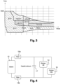
- the requested ratios can be distributed on a graph, like that of the figure 3 .
- This figure allows us to identify the gear changes that may occur during a typical drive. For example, we see that when accelerating at full throttle, we go from HEV22 to HEV32 at around 125 km/h. For this change, the second thermal gear must be disconnected from the transmission to be synchronized with the new thermal gear. With a battery voltage of 270 V, the first ME machine can provide, for example, a power of 35 kW.
- the second HSG machine can provide a power of 25 kW, while the Mth thermal engine provides 70 kW.
- the overall power supplied by the gearbox to the wheel before the change is then 105 kW.
- the gearbox provides approximately the same power (except for the variation in the power of the thermal engine).
- the thermal engine and HSG assembly is disconnected from the wheels. Only the ME then provides power to the wheel, i.e. 35 kW.
- the GMP Powertrain
- the GMP thus suffers from a " power hole " during this gear change.
- the power absorbed by the vehicle's aerodynamics is around 25 kW.
- the power available for acceleration actually drops from 80 kW to 10 kW during the change.
- Such a drop in acceleration (of 87%), gives the driver the impression that his vehicle is no longer accelerating, despite the torque provided by the electric machine.
- main ME Its feel is that of a vehicle equipped with a robotized gearbox with torque break.
- the battery 12 of the vehicle is shown, connected by two relays 13a 13b to the inverters 14, 16 of the two electrical machines, mounted in parallel on the electrical network, with an inverter capacity 17.
- the proposed solution consists in increasing the power supplied by the first main electrical machine ME during the gear changes of the thermal engine (Mth), by operating the second electrical machine (HSG) in regenerative mode. All the electrical power of the latter is then transmitted to the first, which uses it to compensate for the reduction in torque at the wheel caused by the temporary decoupling of the thermal engine.
- the supply voltage of the inverters is increased for this purpose.
- a 450V supply instead of an average voltage of 200V allows the ME to supply approximately 70kW and the HSG to supply approximately 50kW, using the usual components of the electrical network.
- the supply voltage of the inverters is therefore increased to increase the power achievable by the two electrical machines during the gear change.
- the first electrical machine (ME) thus supplies the wheel with all the power transmitted to it by the second electrical machine (HSG).
- the decoupling of the thermal engine is done by disengaging a pinion from its input shaft. Its coupling to a new gear is done by dog-engaging a new pinion on its input shaft.
- the torque of the second HSG electric machine is canceled more quickly than that of the first, to decrease the voltage of the inverters capacity.
- the input shaft 4 linked to the heat engine is synchronized to the target ratio by controlling the torque of the heat engine (Mth), before coupling the heat engine to its input shaft on the new ratio.
- Mth the torque of the heat engine
- the coupling of the heat engine is followed by an increase in torque up to its maximum power.
- the gearbox 1 adopts a series hybrid type operation, where the first electric machine ME can supply to the wheel exactly the power that the HSG supplies to the high-voltage network.
- the thermal engine maintains the speed of the HSG.
- the relays 13a, 13b of the battery 12 are open during the gear change. Their opening makes it possible to increase the voltage on the network in a simple way, preventing the battery from absorbing all the power supplied by the HSG. Disconnecting the battery thus makes it possible to increase the powers achievable during the change.
- FIG. 5 illustrates the evolution of the powers of each component, ME power, HSG power, Mth power and wheel power, during the shift, with the evolution of the thermal engine speed and the corresponding HT (High Voltage) network voltage from stage 1 to 10.
- HT High Voltage
- the power loss during gear change is only 20kW (difference between the maximum power of the Mth equal to 70kW).
- the minimum power during gear change is equal to 50kW.
- the invention results in a transient increase in the voltage of the high voltage (HV) network during gear changes.
- HV high voltage
Landscapes
- Engineering & Computer Science (AREA)
- Transportation (AREA)
- Mechanical Engineering (AREA)
- Chemical & Material Sciences (AREA)
- Combustion & Propulsion (AREA)
- Automation & Control Theory (AREA)
- Power Engineering (AREA)
- Electric Propulsion And Braking For Vehicles (AREA)
- Hybrid Electric Vehicles (AREA)
- Control Of Transmission Device (AREA)
- Control Of Vehicle Engines Or Engines For Specific Uses (AREA)
- Control Of Driving Devices And Active Controlling Of Vehicle (AREA)
Description
- La présente invention concerne le contrôle du couple disponible sur un véhicule hybride pendant les passages de vitesses.
- Plus précisément, elle a pour objet un procédé de contrôle du couple disponible pendant les changements de rapports d'un groupe motopropulseur composé d'un moteur thermique relié à un premier arbre d'entrée de boîte de vitesses qui peut transmettre son couple aux roues sur différents rapports de transmission, d'une première machine électrique reliée à un deuxième arbre d'entrée de celle-ci, et d'une deuxième machine électrique reliée alternativement au premier ou au deuxième arbre d'entrée de la boîte.
- La
publication WO 2014/207332 décrit une transmission hybride de ce type, disposant de plusieurs rapports électriques, thermiques et hybrides, où les couples du moteur thermique et d'au moins une machine électrique s'additionnent en direction des roues. Le couple d'origine thermique est transmis aux roues sur un rapport de transmission « thermique », et celle du couple de la machine électrique principale sur un rapport « électrique ». Lors de changements de rapport de transmission thermique en mode hybride, le couple du moteur thermique est interrompu. Le couple de la machine électrique principale est alors piloté pour synchroniser le moteur thermique sur son nouveau rapport, tout en fournissant du couple à la roue. - Le document
FR 2 847 638 A1 - Dans la pratique, l'architecture électrique du véhicule, en particulier la puissance disponible sur la machine électrique principale, limite l'apport de celle-ci pendant les changements de rapport thermique. Si l'interruption du couple thermique est peu compensée, le conducteur et les passagers du véhicule ressentent ces passages, comme ceux d'une boîte de vitesse robotisée à rupture de couple.
- Il est donc souhaitable de parvenir à estomper la rupture de couple ressentie par le conducteur et les usagers du véhicule, pendant les passages de vitesses.
- Une diminution du couple disponible autour du passage répond en théorie à ce problème. Mais, une telle mesure est inacceptable, pour son impact négatif sur les performances. La solution est donc à rechercher dans une augmentation du couple à la roue pendant les passages. Toute disposition consistant à augmenter temporairement la tension du réseau de bord, présente à cet égard un intérêt. Certains systèmes de batterie, qui ont la faculté de moduler leur tension de sortie par des relais mettant des cellules en série ou bien en parallèle, pourraient notamment contribuer à atténuer le trou de puissance ressenti pendant les passages. Toutefois, ces systèmes ont l'inconvénient d'alourdir, ou même de remettre en cause, l'architecture du véhicule.
- La présente invention vise à augmenter le couple disponible pendant les changements de rapports de transmission thermique, notamment à haute vitesse, afin d'estomper leur « trou de puissance », sans adaptation particulière des composants ou de l'architecture électrique du véhicule.
- Dans ce but, elle propose un procédé de contrôle selon la revendication 1.
- La présente invention sera mieux comprise à la lecture de la description suivante d'un mode de réalisation particulier de celle-ci, en se reportant aux dessins annexés sur lesquels :
- la
figure 1 est un schéma d'architecture hybride, - la
figure 2 regroupe ses courbes de passage, - la
figure 3 identifie les rapports demandés par rapport à ces courbes, et - la
figure 4 est le schéma électrique du réseau de puissance de cette boîte. - La boîte de vitesse 1 de la
figure 1 est par exemple de type « robotisée », c'est-à-dire que son fonctionnement est celui d'une boîte manuelle, mais que les passages de vitesse sont automatisés. Sur le schéma, on a représenté une machine électrique, dite HSG (pour alterno-démarreur haute tension) 2, un moteur thermique 3 sur un arbre primaire plein 4. Une autre machine électrique 5 dite ME, plus puissante que la première, est montée sur un arbre primaire creux 6. L'arbre secondaire de la boîte 7 est relié au différentiel (non représenté), puis aux roues du véhicule. - Le premier crabot 8 situé sur l'arbre secondaire 7 permet de modifier le rapport de la machine électrique ME 5, de façon indépendante du reste de la boîte, pour disposer de deux rapports électriques EV1 et EV2. Le deuxième crabot 9, situé sur l'arbre primaire plein 4, permet de modifier le rapport du moteur thermique 3 de façon indépendante des rapports électriques, pour établir deux rapports thermiques Th2 et Th4, indépendamment du rapport électrique. Le troisième crabot 11, situé sur l'arbre de transfert 10, permet d'établir un troisième rapport thermique Th3, lorsqu'il se déplace vers la droite sur le schéma. Il est possible de choisir de façon indépendante à chaque instant, le rapport voulu sur la première machine électrique ME et celui voulu sur le groupe moteur thermique Mth et la deuxième machine électrique HSG 2. Les combinaisons des rapports thermiques et des rapports électriques permettent de réaliser des rapports hybrides, notés HEVxy, où x désigne le rapport du moteur thermique, et y le rapport de la ME.
- Les courbes de passages de vitesses de la boîte sont regroupées sur la
figure 2 . La boîte 1 permet d'établir deux rapports électriques ZE1 et ZE2, et quatre rapports hybrides Hyb21, Hyb22, Hyb32, Hyb42, en fonction du « rapport thermique » et du « rapport électrique ». Les courbes tracent les efforts maximum réalisables (force aux roues en Newton) sur les rapports électriques et hybrides en fonction de la vitesse. - Dans l'application visée, on peut convenir que le rapport cible soit toujours (quelle que soit la vitesse de déplacement) un rapport électrique ZEV, dès lors que ce rapport de réaliser la demande de couple du conducteur. Par défaut, le rapport engagé devient le rapport hybride le plus long, permettant de réaliser la demande. Dans cette hypothèse, les rapports demandés peuvent se répartir sur un graphe, comme celui de la
figure 3 . Cette figure permet d'identifier les changements de rapport susceptibles de se produire au cours d'un roulage classique. On voit par exemple qu'en accélération en pied à fond, on passe de HEV22 vers HEV32 autour de 125km/h. Pour ce passage, le deuxième rapport thermique doit être déconnecté de la transmission pour être synchronisé sur le nouveau rapport thermique. Avec une tension batterie de 270V, la première machine ME peut fournir par exemple une puissance de 35kW. La deuxième machine HSG peut fournir une puissance de 25kW, tandis que le moteur thermique Mth fournit 70kW. La puissance globale fournie par la boîte à la roue avant le passage, est alors de de 105kW. Après le passage, la boîte fournit sensiblement la même puissance (à la variation de la puissance du moteur thermique près. En revanche, pendant le passage, l'ensemble moteur thermique et HSG est déconnecté des roues. Seule la ME fournit alors de la puissance à la roue, soit 35kW. - Le GMP (Groupe Motopropulseur) souffre ainsi d'un « trou de puissance » lors de ce passage de vitesse. A 125km/h, la puissance absorbée par l'aérodynamique du véhicule est de l'ordre de 25kW. La puissance disponible pour l'accélération passe en réalité de 80kW à 10kW durant le passage. Une telle chute d'accélération (de 87%), donne au conducteur l'impression que son véhicule n'accélère plus, en dépit du couple fourni par la machine électrique principale ME. Son ressenti est celui d'un véhicule doté d'une boîte de vitesse robotisée à rupture de couple.
- Sur la
figure 4 , on a fait apparaître la batterie 12 du véhicule reliée par deux relais 13a 13b aux onduleurs 14, 16 des deux machines électriques, montés en parallèle sur le réseau électrique, avec une capacité d'onduleurs 17. - La solution proposée consiste à augmenter la puissance fournie par la première machine électrique principale ME pendant les changements de rapport de transmission du moteur thermique (Mth), en faisant fonctionner la deuxième machine électrique (HSG) en mode régénératif. Toute la puissance électrique de celle-ci est alors transmise à la première, qui l'utilise pour compenser la diminution de couple à la roue entraînée par le découplage temporaire du moteur thermique. La tension d'alimentation des onduleurs est augmentée à cet effet. Dans l'exemple décrit ci-dessus, une alimentation de 450V au lieu d'une tension moyenne de 200V permet à la ME de fournir environ 70kW et au HSG de fournir environ 50kW, en utilisant les composants habituels du réseau électrique. La tension d'alimentation des onduleurs est donc augmentée pour augmenter la puissance atteignable par les deux machines électriques pendant le changement de rapport. La première machine électrique (ME) fournit ainsi à la roue, toute la puissance que lui transmet la deuxième machine électrique (HSG).
- La méthode proposée est applicable à une boîte telle que celle de la
figure 1 (où les coupleurs sont de préférence des coupleurs à crabots ou clabots, dont l'architecture est schématisée sur lafigure 4 . Elle consiste à enchaîner les étapes suivantes : - 1. annulation des couples de la ME et du HSG,
- 2. ouverture des relais de la batterie,
- 3. passage du HSG en mode régénératif : le HSG régule la tension de la capacité des onduleurs à 450V et fournit alors sur l'arbre du moteur thermique un couple négatif, (limité à la puissance max du HSG à 450V, soit environ 50kW) qui est restitué directement en couple positif à la roue par la ME,
- 4. annulation du couple sur le crabot primaire en diminuant le couple du moteur thermique jusqu'à l'équilibre des puissances du moteur thermique et du HSG : Puissance(Mth) - - Puissance(HSG),
- 5. dé-crabotage du pignon de rapport abandonné sur l'arbre primaire,
- 6. synchronisation de l'arbre primaire sur le rapport cible : si celui-ci est plus long que le rapport abandonné, le régime du moteur thermique est réduit en diminuant davantage son couple (couple Mth),
- 7. crabotage du pignon du nouveau rapport, et augmentation du couple du moteur thermique jusqu'à sa puissance maximum,
- 8. annulation des couples de la ME et du HSG en annulant le couple HSG un peu plus rapidement pour faire diminuer la tension de la capacité de l'onduleur,
- 9. reconnexion des relais de la batterie,
- 10. retour des couples de la ME et du HSG dans la satisfaction globale de la demande de couple du conducteur.
- Lorsque la boîte de vitesse est une boîte de vitesses à crabots ou à clabots, le découplage du moteur thermique s'effectue en dé-crabotant un pignon de son arbre d'entrée. Son couplage sur un nouveau rapport, s'effectue par crabotage d'un nouveau pignon sur son arbre d'entrée.
- La méthode proposée comporte ainsi les étapes suivantes, avant le découplage du moteur thermique et de son arbre d'entrée :
- annulation des couples des deux machines électriques,
- ouverture des relais de la batterie,
- passage de la deuxième machine électrique en mode de récupération d'énergie,
- diminution du couple du moteur thermique jusqu'à l'équilibre de sa propre puissance et de la puissance récupérée par la deuxième machine électrique.
- De préférence, le couple de la deuxième machine électrique HSG est annulé plus rapidement que celui de la première, pour faire diminuer la tension de la capacité des onduleurs.
- Après son découplage, l'arbre d'entrée 4 lié au moteur thermique est synchronisé sur le rapport ciblé en pilotant le couple du moteur thermique (Mth), avant le couplage du moteur thermique à son arbre d'entrée sur le nouveau rapport. De préférence, le couplage du moteur thermique est suivi d'une augmentation de couple jusqu'à sa puissance maximum.
- Pendant le changement de rapport, la boîte de vitesses 1 adopte un fonctionnement de type hybride série, où la première machine électrique ME peut fournir à la roue exactement la puissance que fournit le HSG au réseau haute tension. Le moteur thermique maintient le régime du HSG. Les relais 13a, 13b de la batterie 12 sont ouverts pendant le changement de rapport. Leur ouverture permet d'augmenter de façon simple la tension sur le réseau, en évitant que la batterie absorbe toute la puissance fournie par le HSG. La mise hors circuit de la batterie permet ainsi d'augmenter les puissances réalisables pendant le passage.
- La
figure 5 illustre l'évolution des puissances de chaque organe, puissance ME, puissance HSG, puissance Mth et puissance à la roue, au cours du passage, avec l'évolution du régime du moteur thermique et la tension de réseau HT (Haute Tension) correspondantes de l'étape 1 à 10. Ces courbes mettent en évidence le gain apporté par l'invention. Sans compensation pendant le changement de rapport, la puissance à la roue serait tombée à 35kW. Grâce à l'invention, on maintient la puissance à la roue à 70kW pendant trois étapes, et à 50kW pendant une étape. Le « trou de puissance » reste ainsi inférieur à 50%. La perte d'accélération est réduite, de sorte que le conducteur ressent en permanence la disponibilité de puissance pour accélérer. - Il est par ailleurs toujours possible d'augmenter la tension du réseau, pour réduire davantage le trou de puissance. Toutefois, cette adaptation peut exiger le redimensionnement de certains composants du système, ce qui n'est pas le cas avec les simples mesures de commande proposés par l'invention.
- Dans le cas d'un véhicule de catégorie dite « mild hybrid » ou la machine électrique principale est principalement destinée à une fonction de relance (ou « boost »), ou au roulage à basse vitesse, on peut faire le choix de limiter la puissance disponible à haute vitesse à celle du moteur thermique, notamment en cas d'accélération pied à fond, pour ne pas vider la batterie trop rapidement. Dans l'exemple décrit, la perte de puissance pendant le changement de rapport, n'est plus que de 20kW (différence entre la puissance maximum du Mth égale à 70kW). La puissance minimale pendant le changement de rapport est égale à 50kW.
- En conclusion, l'invention se traduit par une élévation transitoire de la tension du réseau haute tension (HT) pendant les passages de vitesses. L'intérêt majeur de de l'invention est qu'elle ne nécessite aucun ajout dans le système, si on se limite à 450V maximum sur le réseau dans l'exemple décrit.
Claims (7)
- Procédé de contrôle du couple disponible pendant les changements de rapports d'un groupe motopropulseur composé d'un moteur thermique (Mth) relié à un premier arbre d'entrée (4) de boîte de vitesses qui peut transmettre son couple aux roues sur différents rapports de transmission, d'une première machine électrique (ME) reliée à un deuxième arbre d'entrée (6) de celle-ci, et d'une deuxième machine électrique (HSG) reliée au premier arbre d'entrée de la boîte, la deuxième machine électrique (HSG) passant, pendant les changements de rapport de transmission du moteur thermique (Mth), en mode régénératif avant le découplage du moteur thermique, pour transmettre toute sa puissance électrique à la première machine électrique (ME) qui l'utilise pour compenser la diminution de couple à la roue entraînée par le découplage temporaire du moteur thermique, et ledit procédé comportant les étapes suivantes, avant le découplage du moteur thermique et de son arbre d'entrée (4) :- annulation des couples des deux machines électriques (ME), (HSG),- passage de la deuxième machine électrique en mode de récupération d'énergie,- diminution du couple du moteur thermique jusqu'à l'équilibre de sa propre puissance et de la puissance récupérée par la deuxième machine électrique,caractérisé en ce que ledit procédé comprend également les étapes suivantes, avant le découplage du moteur thermique et de son arbre d'entrée (4):- augmentation de la tension d'alimentation des onduleurs pour augmenter la puissance fournie par les deux machines électriques pendant le changement de rapport, et- ouverture des relais (13a, 13b) de la batterie (12).
- Procédé de contrôle de couple selon la revendication 1, caractérisé en ce que la première machine électrique (ME) fournit à la roue la puissance que lui fournit la deuxième machine électrique (HSG).
- Procédé de contrôle selon l'une des revendications précédentes, caractérisé en ce que le couple de la deuxième machine électrique (HSG) est annulé plus rapidement que celui de la première (ME), pour faire diminuer la tension de la capacité des onduleurs.
- Procédé de contrôle selon l'une des revendications précédentes, caractérisé en ce que le découplage du moteur thermique s'effectue en dé-crabotant un pignon de son arbre d'entrée (4).
- Procédé de contrôle du couple selon la revendication 1 ou 2, caractérisé en ce que après son découplage, l'arbre d'entrée lié au moteur thermique est synchronisé sur le rapport ciblé en pilotant le couple du moteur thermique (Mth).
- Procédé de contrôle de couple selon la revendication 3, caractérisé en ce que le couplage du moteur thermique sur son nouveau rapport de transmission s'effectue par crabotage d'un nouveau pignon sur son arbre d'entrée (4).
- Procédé de contrôle du couple selon la revendication 5 ou 6, caractérisé en ce que le couplage du moteur thermique est suivi d'une augmentation de couple (Mth) jusqu'à sa puissance maximum.
Applications Claiming Priority (2)
| Application Number | Priority Date | Filing Date | Title |
|---|---|---|---|
| FR1654522A FR3051419B1 (fr) | 2016-05-20 | 2016-05-20 | Procede de controle du couple disponible sur un vehicule hybride pendant les passages de vitesses |
| PCT/FR2017/050494 WO2017198913A1 (fr) | 2016-05-20 | 2017-03-06 | Procede de controle du couple disponible sur un vehicule hybride pendant les passages de vitesses |
Publications (2)
| Publication Number | Publication Date |
|---|---|
| EP3458293A1 EP3458293A1 (fr) | 2019-03-27 |
| EP3458293B1 true EP3458293B1 (fr) | 2024-12-25 |
Family
ID=56511761
Family Applications (1)
| Application Number | Title | Priority Date | Filing Date |
|---|---|---|---|
| EP17715515.7A Active EP3458293B1 (fr) | 2016-05-20 | 2017-03-06 | Procede de controle du couple disponible sur un vehicule hybride pendant les passages de vitesses |
Country Status (12)
| Country | Link |
|---|---|
| US (1) | US20190315336A1 (fr) |
| EP (1) | EP3458293B1 (fr) |
| JP (1) | JP7090556B2 (fr) |
| KR (2) | KR20190009762A (fr) |
| CN (1) | CN109996696B (fr) |
| BR (1) | BR112018073766A2 (fr) |
| CA (1) | CA3024921A1 (fr) |
| FR (1) | FR3051419B1 (fr) |
| MA (1) | MA45345A (fr) |
| MX (1) | MX2018013954A (fr) |
| RU (1) | RU2018144581A (fr) |
| WO (1) | WO2017198913A1 (fr) |
Families Citing this family (8)
| Publication number | Priority date | Publication date | Assignee | Title |
|---|---|---|---|---|
| FR3053299B1 (fr) * | 2016-06-30 | 2019-08-02 | Renault S.A.S | Procede et dispositif de controle de la puissance disponible sur une chaine de traction electrique d'un groupe motopropulseur hybride |
| US10780770B2 (en) * | 2018-10-05 | 2020-09-22 | Polaris Industries Inc. | Hybrid utility vehicle |
| FR3099115B1 (fr) * | 2019-07-22 | 2021-06-18 | Renault Sas | Procédé de commande, lors des passages de vitesses, des réseaux d’alimentation électrique d’un véhicule hybride équipé d’une boite de vitesse robotisée. |
| FR3110127B1 (fr) | 2020-05-13 | 2022-06-24 | Renault Sas | Procédé de gestion de l’énergie pour un véhicule automobile hybride |
| KR102890897B1 (ko) * | 2020-10-12 | 2025-11-27 | 현대자동차주식회사 | 하이브리드 자동차 및 그 제어 방법 |
| JP7582022B2 (ja) * | 2021-03-31 | 2024-11-13 | 株式会社アイシン | 車両用駆動装置 |
| FR3156405B1 (fr) * | 2023-12-07 | 2025-10-31 | Ampere Sas | Procédé et dispositif de gestion du fonctionnement d’un moteur thermique d’un véhicule automobile hybride équipé d’une boite de vitesses à crabots |
| FR3156402B1 (fr) * | 2023-12-07 | 2025-10-31 | Ampere Sas | Procédé et dispositif de gestion du fonctionnement d’un moteur thermique d’un véhicule automobile hybride équipé d’une boite de vitesses à crabots |
Family Cites Families (12)
| Publication number | Priority date | Publication date | Assignee | Title |
|---|---|---|---|---|
| DE19881999D2 (de) * | 1997-12-23 | 2000-06-15 | Luk Getriebe Systeme Gmbh | Getriebe |
| JP3715272B2 (ja) * | 2002-11-21 | 2005-11-09 | トヨタ自動車株式会社 | 車両の動力伝達装置 |
| JP4200805B2 (ja) * | 2003-04-22 | 2008-12-24 | トヨタ自動車株式会社 | 車両の変速時制御方法 |
| JP4405374B2 (ja) * | 2004-11-26 | 2010-01-27 | アイシン精機株式会社 | 有段変速機を備えた車両のトルク制御装置 |
| JP5228324B2 (ja) | 2007-01-17 | 2013-07-03 | 日産自動車株式会社 | 電動車両 |
| CN101244687B (zh) * | 2008-03-20 | 2010-04-21 | 上海交通大学 | 混联式混合动力驱动系统及其驱动方法 |
| DE102008043849A1 (de) * | 2008-11-19 | 2010-05-20 | Zf Friedrichshafen Ag | Mehrachsiges Hybrid-Antriebssystem für ein Fahrzeug |
| US20130020972A1 (en) | 2010-03-02 | 2013-01-24 | Honda Motor Co., Ltd. | Load drive apparatus |
| EP2676855B1 (fr) * | 2011-02-16 | 2018-07-25 | Toyota Jidosha Kabushiki Kaisha | Véhicule et procédé de commande de véhicule |
| CN103332100A (zh) * | 2012-12-07 | 2013-10-02 | 常州万安汽车部件科技有限公司 | 多模式混合动力系统及其驱动方法 |
| CN105143002B (zh) * | 2013-04-23 | 2017-11-28 | 三菱电机株式会社 | 混合动力车辆的控制装置以及控制方法 |
| FR3007696B1 (fr) * | 2013-06-26 | 2015-06-26 | Renault Sa | Transmission hybride avec une machine electrique additionnelle et procede de commande |
-
2016
- 2016-05-20 FR FR1654522A patent/FR3051419B1/fr active Active
-
2017
- 2017-03-06 MX MX2018013954A patent/MX2018013954A/es unknown
- 2017-03-06 KR KR1020187035397A patent/KR20190009762A/ko not_active Ceased
- 2017-03-06 US US16/302,875 patent/US20190315336A1/en not_active Abandoned
- 2017-03-06 RU RU2018144581A patent/RU2018144581A/ru not_active Application Discontinuation
- 2017-03-06 MA MA045345A patent/MA45345A/fr unknown
- 2017-03-06 CA CA3024921A patent/CA3024921A1/fr not_active Abandoned
- 2017-03-06 WO PCT/FR2017/050494 patent/WO2017198913A1/fr not_active Ceased
- 2017-03-06 KR KR1020217034659A patent/KR102444255B1/ko active Active
- 2017-03-06 EP EP17715515.7A patent/EP3458293B1/fr active Active
- 2017-03-06 CN CN201780044263.4A patent/CN109996696B/zh active Active
- 2017-03-06 JP JP2018560794A patent/JP7090556B2/ja active Active
- 2017-03-06 BR BR112018073766-6A patent/BR112018073766A2/pt not_active Application Discontinuation
Also Published As
| Publication number | Publication date |
|---|---|
| WO2017198913A1 (fr) | 2017-11-23 |
| CA3024921A1 (fr) | 2017-11-23 |
| KR102444255B1 (ko) | 2022-09-16 |
| RU2018144581A (ru) | 2020-06-22 |
| MX2018013954A (es) | 2019-03-21 |
| CN109996696B (zh) | 2023-01-17 |
| JP7090556B2 (ja) | 2022-06-24 |
| KR20210130855A (ko) | 2021-11-01 |
| CN109996696A (zh) | 2019-07-09 |
| JP2019518647A (ja) | 2019-07-04 |
| FR3051419A1 (fr) | 2017-11-24 |
| FR3051419B1 (fr) | 2021-07-30 |
| US20190315336A1 (en) | 2019-10-17 |
| KR20190009762A (ko) | 2019-01-29 |
| BR112018073766A2 (pt) | 2019-02-26 |
| MA45345A (fr) | 2019-03-27 |
| EP3458293A1 (fr) | 2019-03-27 |
Similar Documents
| Publication | Publication Date | Title |
|---|---|---|
| EP3458293A1 (fr) | Procede de controle du couple disponible sur un vehicule hybride pendant les passages de vitesses | |
| NL2002375B1 (nl) | Vliegwielmodule, alsmede werkwijze voor het opslaan en vrijgeven van energie in de vliegwielmodule. | |
| DE102011077594B4 (de) | Hybridantrieb | |
| EP3160786A1 (fr) | Transmission hybride a machine électrique déportée et procédé de commande de changements de rapports | |
| DE102013005252A1 (de) | Hybrid-Antriebsstrang und Verfahren zum Steuern desselben | |
| CN103978976A (zh) | 用于操作混合动力双离合器变速器传动系统的方法 | |
| EP2726757A1 (fr) | Architecture électrique de véhicule hybride, véhicule hybride et procédé de commande | |
| EP3164285B1 (fr) | Procede de commande de systeme de motorisation hybride, pour un vehicule hybride | |
| EP3478529B1 (fr) | Procédé et dispositif de contrôle de la puissance disponible sur une chaîne de traction électrique d'un groupe motopropulseur hybride | |
| FR2994404A1 (fr) | Procede de limitation de couple d'une machine electrique de vehicule hybride, comportant des limites de couple nominal et crete | |
| EP3589510B1 (fr) | Dispositif de contrôle des couplages/découplages d'une machine motrice d'un véhicule lors d'un changement de rapport | |
| FR2996510A1 (fr) | Procede et dispositif d’aide aux decisions de couplage/ decouplage d'une machine d'un vehicule hybride, en fonction du couple offert par le moteur thermique | |
| DE102011112753B4 (de) | Hybridantriebsstrang und Verfahren zum Betreiben desselben | |
| US12227069B2 (en) | Drive system for variable distribution of torque to wheels of a vehicle | |
| FR3070347B1 (fr) | Controle d’instants de declenchement d’une marche rampante par des moteur thermique et machine motrice non-thermique d’un vehicule hybride | |
| WO2016005668A1 (fr) | Procédé de sélection de la consigne d'état d'une chaîne cinématique | |
| FR3064575B1 (fr) | Dispositif de controle des couplages/decouplages d'une machine motrice non-thermique d'un vehicule en fonction d'un parametre d'etat de moyens de stockage associes | |
| JP2015140163A (ja) | 車両用駆動装置及びその制御方法 | |
| KR102908677B1 (ko) | 하이브리드 차량의 동력 전달 시스템 및 그 제어 방법 | |
| FR3166121A1 (fr) | Optimisation de la lutte contre les oscillations d’une chaîne de transmission électrique ou hybride d’un véhicule | |
| EP3621862A1 (fr) | Dispositif et procédé de contrôle de l'allocation de la puissance de moyens de stockage d'énergie d'un véhicule | |
| WO2025099370A1 (fr) | Contrôle du régime de l'arbre primaire d'une boîte de vitesse à double embrayage d'un véhicule | |
| FR3070344A1 (fr) | Dispositif et procede de controle de l’intensite de deceleration d’un vehicule hybride induite par une machine non-thermique |
Legal Events
| Date | Code | Title | Description |
|---|---|---|---|
| STAA | Information on the status of an ep patent application or granted ep patent |
Free format text: STATUS: UNKNOWN |
|
| STAA | Information on the status of an ep patent application or granted ep patent |
Free format text: STATUS: THE INTERNATIONAL PUBLICATION HAS BEEN MADE |
|
| PUAI | Public reference made under article 153(3) epc to a published international application that has entered the european phase |
Free format text: ORIGINAL CODE: 0009012 |
|
| STAA | Information on the status of an ep patent application or granted ep patent |
Free format text: STATUS: REQUEST FOR EXAMINATION WAS MADE |
|
| 17P | Request for examination filed |
Effective date: 20181211 |
|
| AK | Designated contracting states |
Kind code of ref document: A1 Designated state(s): AL AT BE BG CH CY CZ DE DK EE ES FI FR GB GR HR HU IE IS IT LI LT LU LV MC MK MT NL NO PL PT RO RS SE SI SK SM TR |
|
| AX | Request for extension of the european patent |
Extension state: BA ME |
|
| DAX | Request for extension of the european patent (deleted) | ||
| RAV | Requested validation state of the european patent: fee paid |
Extension state: MA Effective date: 20181211 |
|
| RAP3 | Party data changed (applicant data changed or rights of an application transferred) |
Owner name: NISSAN MOTOR CO., LTD. Owner name: RENAULT S.A.S |
|
| STAA | Information on the status of an ep patent application or granted ep patent |
Free format text: STATUS: EXAMINATION IS IN PROGRESS |
|
| 17Q | First examination report despatched |
Effective date: 20220627 |
|
| RAP3 | Party data changed (applicant data changed or rights of an application transferred) |
Owner name: NISSAN MOTOR CO., LTD. Owner name: RENAULT S.A.S |
|
| GRAP | Despatch of communication of intention to grant a patent |
Free format text: ORIGINAL CODE: EPIDOSNIGR1 |
|
| STAA | Information on the status of an ep patent application or granted ep patent |
Free format text: STATUS: GRANT OF PATENT IS INTENDED |
|
| INTG | Intention to grant announced |
Effective date: 20240724 |
|
| GRAS | Grant fee paid |
Free format text: ORIGINAL CODE: EPIDOSNIGR3 |
|
| GRAA | (expected) grant |
Free format text: ORIGINAL CODE: 0009210 |
|
| STAA | Information on the status of an ep patent application or granted ep patent |
Free format text: STATUS: THE PATENT HAS BEEN GRANTED |
|
| AK | Designated contracting states |
Kind code of ref document: B1 Designated state(s): AL AT BE BG CH CY CZ DE DK EE ES FI FR GB GR HR HU IE IS IT LI LT LU LV MC MK MT NL NO PL PT RO RS SE SI SK SM TR |
|
| REG | Reference to a national code |
Ref country code: GB Ref legal event code: FG4D Free format text: NOT ENGLISH |
|
| REG | Reference to a national code |
Ref country code: CH Ref legal event code: EP |
|
| REG | Reference to a national code |
Ref country code: DE Ref legal event code: R096 Ref document number: 602017086939 Country of ref document: DE |
|
| REG | Reference to a national code |
Ref country code: IE Ref legal event code: FG4D Free format text: LANGUAGE OF EP DOCUMENT: FRENCH |
|
| REG | Reference to a national code |
Ref country code: LT Ref legal event code: MG9D |
|
| PG25 | Lapsed in a contracting state [announced via postgrant information from national office to epo] |
Ref country code: HR Free format text: LAPSE BECAUSE OF FAILURE TO SUBMIT A TRANSLATION OF THE DESCRIPTION OR TO PAY THE FEE WITHIN THE PRESCRIBED TIME-LIMIT Effective date: 20241225 |
|
| PG25 | Lapsed in a contracting state [announced via postgrant information from national office to epo] |
Ref country code: FI Free format text: LAPSE BECAUSE OF FAILURE TO SUBMIT A TRANSLATION OF THE DESCRIPTION OR TO PAY THE FEE WITHIN THE PRESCRIBED TIME-LIMIT Effective date: 20241225 |
|
| PG25 | Lapsed in a contracting state [announced via postgrant information from national office to epo] |
Ref country code: BG Free format text: LAPSE BECAUSE OF FAILURE TO SUBMIT A TRANSLATION OF THE DESCRIPTION OR TO PAY THE FEE WITHIN THE PRESCRIBED TIME-LIMIT Effective date: 20241225 |
|
| PG25 | Lapsed in a contracting state [announced via postgrant information from national office to epo] |
Ref country code: NO Free format text: LAPSE BECAUSE OF FAILURE TO SUBMIT A TRANSLATION OF THE DESCRIPTION OR TO PAY THE FEE WITHIN THE PRESCRIBED TIME-LIMIT Effective date: 20250325 |
|
| PG25 | Lapsed in a contracting state [announced via postgrant information from national office to epo] |
Ref country code: GR Free format text: LAPSE BECAUSE OF FAILURE TO SUBMIT A TRANSLATION OF THE DESCRIPTION OR TO PAY THE FEE WITHIN THE PRESCRIBED TIME-LIMIT Effective date: 20250326 Ref country code: LV Free format text: LAPSE BECAUSE OF FAILURE TO SUBMIT A TRANSLATION OF THE DESCRIPTION OR TO PAY THE FEE WITHIN THE PRESCRIBED TIME-LIMIT Effective date: 20241225 |
|
| PG25 | Lapsed in a contracting state [announced via postgrant information from national office to epo] |
Ref country code: RS Free format text: LAPSE BECAUSE OF FAILURE TO SUBMIT A TRANSLATION OF THE DESCRIPTION OR TO PAY THE FEE WITHIN THE PRESCRIBED TIME-LIMIT Effective date: 20250325 |
|
| REG | Reference to a national code |
Ref country code: NL Ref legal event code: MP Effective date: 20241225 |
|
| PG25 | Lapsed in a contracting state [announced via postgrant information from national office to epo] |
Ref country code: NL Free format text: LAPSE BECAUSE OF FAILURE TO SUBMIT A TRANSLATION OF THE DESCRIPTION OR TO PAY THE FEE WITHIN THE PRESCRIBED TIME-LIMIT Effective date: 20241225 |
|
| REG | Reference to a national code |
Ref country code: AT Ref legal event code: MK05 Ref document number: 1753895 Country of ref document: AT Kind code of ref document: T Effective date: 20241225 |
|
| PG25 | Lapsed in a contracting state [announced via postgrant information from national office to epo] |
Ref country code: SM Free format text: LAPSE BECAUSE OF FAILURE TO SUBMIT A TRANSLATION OF THE DESCRIPTION OR TO PAY THE FEE WITHIN THE PRESCRIBED TIME-LIMIT Effective date: 20241225 |
|
| PG25 | Lapsed in a contracting state [announced via postgrant information from national office to epo] |
Ref country code: PL Free format text: LAPSE BECAUSE OF FAILURE TO SUBMIT A TRANSLATION OF THE DESCRIPTION OR TO PAY THE FEE WITHIN THE PRESCRIBED TIME-LIMIT Effective date: 20241225 |
|
| PG25 | Lapsed in a contracting state [announced via postgrant information from national office to epo] |
Ref country code: ES Free format text: LAPSE BECAUSE OF FAILURE TO SUBMIT A TRANSLATION OF THE DESCRIPTION OR TO PAY THE FEE WITHIN THE PRESCRIBED TIME-LIMIT Effective date: 20241225 |
|
| PG25 | Lapsed in a contracting state [announced via postgrant information from national office to epo] |
Ref country code: IS Free format text: LAPSE BECAUSE OF FAILURE TO SUBMIT A TRANSLATION OF THE DESCRIPTION OR TO PAY THE FEE WITHIN THE PRESCRIBED TIME-LIMIT Effective date: 20250425 |
|
| PG25 | Lapsed in a contracting state [announced via postgrant information from national office to epo] |
Ref country code: PT Free format text: LAPSE BECAUSE OF FAILURE TO SUBMIT A TRANSLATION OF THE DESCRIPTION OR TO PAY THE FEE WITHIN THE PRESCRIBED TIME-LIMIT Effective date: 20250428 |
|
| PG25 | Lapsed in a contracting state [announced via postgrant information from national office to epo] |
Ref country code: EE Free format text: LAPSE BECAUSE OF FAILURE TO SUBMIT A TRANSLATION OF THE DESCRIPTION OR TO PAY THE FEE WITHIN THE PRESCRIBED TIME-LIMIT Effective date: 20241225 |
|
| PG25 | Lapsed in a contracting state [announced via postgrant information from national office to epo] |
Ref country code: AT Free format text: LAPSE BECAUSE OF FAILURE TO SUBMIT A TRANSLATION OF THE DESCRIPTION OR TO PAY THE FEE WITHIN THE PRESCRIBED TIME-LIMIT Effective date: 20241225 Ref country code: RO Free format text: LAPSE BECAUSE OF FAILURE TO SUBMIT A TRANSLATION OF THE DESCRIPTION OR TO PAY THE FEE WITHIN THE PRESCRIBED TIME-LIMIT Effective date: 20241225 |
|
| PG25 | Lapsed in a contracting state [announced via postgrant information from national office to epo] |
Ref country code: SK Free format text: LAPSE BECAUSE OF FAILURE TO SUBMIT A TRANSLATION OF THE DESCRIPTION OR TO PAY THE FEE WITHIN THE PRESCRIBED TIME-LIMIT Effective date: 20241225 |
|
| PG25 | Lapsed in a contracting state [announced via postgrant information from national office to epo] |
Ref country code: CZ Free format text: LAPSE BECAUSE OF FAILURE TO SUBMIT A TRANSLATION OF THE DESCRIPTION OR TO PAY THE FEE WITHIN THE PRESCRIBED TIME-LIMIT Effective date: 20241225 |
|
| PG25 | Lapsed in a contracting state [announced via postgrant information from national office to epo] |
Ref country code: IT Free format text: LAPSE BECAUSE OF FAILURE TO SUBMIT A TRANSLATION OF THE DESCRIPTION OR TO PAY THE FEE WITHIN THE PRESCRIBED TIME-LIMIT Effective date: 20241225 |
|
| PG25 | Lapsed in a contracting state [announced via postgrant information from national office to epo] |
Ref country code: SE Free format text: LAPSE BECAUSE OF FAILURE TO SUBMIT A TRANSLATION OF THE DESCRIPTION OR TO PAY THE FEE WITHIN THE PRESCRIBED TIME-LIMIT Effective date: 20241225 |
|
| REG | Reference to a national code |
Ref country code: DE Ref legal event code: R097 Ref document number: 602017086939 Country of ref document: DE |
|
| PG25 | Lapsed in a contracting state [announced via postgrant information from national office to epo] |
Ref country code: DK Free format text: LAPSE BECAUSE OF FAILURE TO SUBMIT A TRANSLATION OF THE DESCRIPTION OR TO PAY THE FEE WITHIN THE PRESCRIBED TIME-LIMIT Effective date: 20241225 |
|
| PG25 | Lapsed in a contracting state [announced via postgrant information from national office to epo] |
Ref country code: MC Free format text: LAPSE BECAUSE OF FAILURE TO SUBMIT A TRANSLATION OF THE DESCRIPTION OR TO PAY THE FEE WITHIN THE PRESCRIBED TIME-LIMIT Effective date: 20241225 |
|
| REG | Reference to a national code |
Ref country code: CH Ref legal event code: H13 Free format text: ST27 STATUS EVENT CODE: U-0-0-H10-H13 (AS PROVIDED BY THE NATIONAL OFFICE) Effective date: 20251024 |
|
| PLBE | No opposition filed within time limit |
Free format text: ORIGINAL CODE: 0009261 |
|
| STAA | Information on the status of an ep patent application or granted ep patent |
Free format text: STATUS: NO OPPOSITION FILED WITHIN TIME LIMIT |
|
| PG25 | Lapsed in a contracting state [announced via postgrant information from national office to epo] |
Ref country code: LU Free format text: LAPSE BECAUSE OF NON-PAYMENT OF DUE FEES Effective date: 20250306 |
|
| 26N | No opposition filed |
Effective date: 20250926 |
|
| REG | Reference to a national code |
Ref country code: BE Ref legal event code: MM Effective date: 20250331 |
|
| PG25 | Lapsed in a contracting state [announced via postgrant information from national office to epo] |
Ref country code: BE Free format text: LAPSE BECAUSE OF NON-PAYMENT OF DUE FEES Effective date: 20250331 |
|
| PG25 | Lapsed in a contracting state [announced via postgrant information from national office to epo] |
Ref country code: CH Free format text: LAPSE BECAUSE OF NON-PAYMENT OF DUE FEES Effective date: 20250331 |
|
| PG25 | Lapsed in a contracting state [announced via postgrant information from national office to epo] |
Ref country code: IE Free format text: LAPSE BECAUSE OF NON-PAYMENT OF DUE FEES Effective date: 20250306 |
|
| PGFP | Annual fee paid to national office [announced via postgrant information from national office to epo] |
Ref country code: GB Payment date: 20260324 Year of fee payment: 10 |
|
| PGFP | Annual fee paid to national office [announced via postgrant information from national office to epo] |
Ref country code: DE Payment date: 20260319 Year of fee payment: 10 |
|
| VS25 | Lapsed in a validation state [announced via postgrant information from nat. office to epo] |
Ref country code: MA Free format text: LAPSE BECAUSE OF FAILURE TO SUBMIT A TRANSLATION OF THE DESCRIPTION OR TO PAY THE FEE WITHIN THE PRESCRIBED TIME-LIMIT; INVALID AB INITIO Effective date: 20170306 |
|
| PGFP | Annual fee paid to national office [announced via postgrant information from national office to epo] |
Ref country code: FR Payment date: 20260320 Year of fee payment: 10 |